JP2008257381A - Information analyzing system, information analyzing device, information analyzing method, information analyzing program, and recording medium - Google Patents
Information analyzing system, information analyzing device, information analyzing method, information analyzing program, and recording medium Download PDFInfo
- Publication number
- JP2008257381A JP2008257381A JP2007097294A JP2007097294A JP2008257381A JP 2008257381 A JP2008257381 A JP 2008257381A JP 2007097294 A JP2007097294 A JP 2007097294A JP 2007097294 A JP2007097294 A JP 2007097294A JP 2008257381 A JP2008257381 A JP 2008257381A
- Authority
- JP
- Japan
- Prior art keywords
- user
- information
- analysis
- image
- unit
- Prior art date
- Legal status (The legal status is an assumption and is not a legal conclusion. Google has not performed a legal analysis and makes no representation as to the accuracy of the status listed.)
- Pending
Links
Images


Landscapes
- Image Analysis (AREA)
- Processing Or Creating Images (AREA)
- Image Processing (AREA)
- Closed-Circuit Television Systems (AREA)
- Management, Administration, Business Operations System, And Electronic Commerce (AREA)
Abstract
Description
この発明は、ユーザに関して取得された情報を解析した結果に基づき、当該ユーザに対して情報を配信する情報解析システム、情報解析装置、情報解析方法および情報解析プログラム、ならびに、記録媒体に関する。 The present invention relates to an information analysis system, an information analysis apparatus, an information analysis method, an information analysis program, and a recording medium that distribute information to a user based on a result of analyzing information acquired about the user.
ユーザは自分の位置情報や時刻情報を記憶するようにされた利用者メディアを持ち歩き、所定のエリアや施設内にットワーク接続された撮影装置を複数台設置して常時撮影を行うようにしたシステムが本発明の出願人により提案され、特許文献1に記載されている。この特許文献1によるシステムでは、ユーザは、自分が撮影されている写真や映像の提供を受けたいと考えたときに、利用者メディアに記憶されている情報をシステムに読み取らせる。システム側では、利用者メディアから読み取った位置および時刻情報に基づき当該ユーザが撮影されている写真や映像を抽出し、例えばディスク、メモリカードといった可搬性の記録媒体に記録したり、ネットワークによる通信を利用してユーザに提供する。
この特許文献1に記載されるようなシステムにおいて、撮影装置により撮影された写真や映像を解析し、解析結果をユーザに提供できるシステムが望まれている。特に、解析結果に基づき特定の結論を導くことができ、その結論をユーザに提供できるようなシステムが望まれている。
In the system described in
したがって、この発明の目的は、センサ装置によりユーザに関する情報を取得し、取得された情報を解析して特定の結論を導き出してユーザに提供できるようにした情報解析システム、情報解析装置、情報解析方法および情報解析プログラム、ならびに、記録媒体を提供することにある。 Therefore, an object of the present invention is to provide an information analysis system, an information analysis apparatus, and an information analysis method that acquire information related to a user by a sensor device, analyze the acquired information, derive a specific conclusion, and provide the user with the information. And providing an information analysis program and a recording medium.
上述した課題を解決するために、第1の発明は、画像データを解析した結果に応じた情報を出力する情報解析装置において、画像データからユーザの身体に関連する画像を検出する画像検出部と、画像検出部で検出されたユーザの身体に関連する画像に基づき第1の所定の解析処理を行う第1の解析部と、第1の解析部による解析結果と閾値とを比較する比較部と、画像検出部で検出されたユーザの身体に関連する画像に基づき第2の所定の解析処理を行う第2の解析部とを有し、比較部による比較結果に基づき、第2の解析部による第2の所定の解析処理を行うか否かを決定することを特徴とする情報解析装置である。 In order to solve the above-described problems, a first invention is an information analysis apparatus that outputs information according to a result of analyzing image data. An image detection unit that detects an image related to a user's body from image data; A first analysis unit that performs a first predetermined analysis process based on an image related to the user's body detected by the image detection unit, and a comparison unit that compares an analysis result of the first analysis unit with a threshold value A second analysis unit that performs a second predetermined analysis process based on an image related to the user's body detected by the image detection unit, and based on a comparison result by the comparison unit, It is an information analysis apparatus characterized by determining whether or not to perform a second predetermined analysis process.
また、第2の発明は、画像データを解析した結果に応じた情報を出力する情報解析方法において、画像データからユーザの身体に関連する画像を検出する画像検出のステップと、画像検出のステップにより検出されたユーザの身体に関連する画像に基づき第1の所定の解析処理を行う第1の解析のステップと、第1の解析のステップによる解析結果と閾値とを比較する比較のステップと、画像検出のステップにより検出されたユーザの身体に関連する画像に基づき第2の所定の解析処理を行う第2の解析のステップとを有し、比較のステップによる比較結果に基づき、第2の解析のステップによる第2の所定の解析処理を行うか否かを決定することを特徴とする情報解析方法である。 According to a second aspect of the present invention, there is provided an information analysis method for outputting information according to a result of analyzing image data, the image detection step for detecting an image related to the user's body from the image data, and the image detection step. A first analysis step for performing a first predetermined analysis process based on the detected image relating to the user's body, a comparison step for comparing an analysis result of the first analysis step with a threshold value, and an image And a second analysis step for performing a second predetermined analysis process based on the image related to the user's body detected in the detection step, and based on the comparison result in the comparison step, It is an information analysis method characterized by determining whether or not to perform a second predetermined analysis process in steps.
また、第3の発明は、画像データを解析した結果に応じた情報を出力する情報解析方法をコンピュータに実行させる情報解析プログラムにおいて、情報解析方法は、画像データからユーザの身体に関連する画像を検出する画像検出のステップと、画像検出のステップにより検出されたユーザの身体に関連する画像に基づき第1の所定の解析処理を行う第1の解析のステップと、第1の解析のステップによる解析結果と閾値とを比較する比較のステップと、画像検出のステップにより検出されたユーザの身体に関連する画像に基づき第2の所定の解析処理を行う第2の解析のステップとを有し、比較のステップによる比較結果に基づき、第2の解析のステップによる第2の所定の解析処理を行うか否かを決定することを特徴とする情報解析プログラムである。 According to a third aspect of the present invention, there is provided an information analysis program for causing a computer to execute an information analysis method for outputting information corresponding to a result of analyzing image data. The information analysis method includes: An image detection step to detect, a first analysis step for performing a first predetermined analysis process based on an image related to the user's body detected by the image detection step, and an analysis by the first analysis step A comparison step for comparing the result with a threshold value, and a second analysis step for performing a second predetermined analysis process based on an image related to the user's body detected by the image detection step. And determining whether or not to perform the second predetermined analysis process in the second analysis step based on the comparison result in the step of It is a lamb.
また、第4の発明は、画像データを解析した結果に応じた情報を出力する情報解析方法をコンピュータに実行させる情報解析プログラムが記録されるコンピュータに読み取り可能な記録媒体において、画像データからユーザの身体に関連する画像を検出する画像検出のステップと、画像検出のステップにより検出されたユーザの身体に関連する画像と、ユーザの身体に関連する画像に対応する参照画像に基づく値との差分に基づき第1の所定の解析処理を行う第1の解析のステップと、第1の解析のステップによる解析結果と閾値とを比較する比較のステップと、画像検出のステップにより検出されたユーザの身体に関連する画像に基づき第2の所定の解析処理を行う第2の解析のステップとを有し、比較のステップによる比較結果に基づき、第2の解析のステップによる第2の所定の解析処理を行うか否かを決定するようにした情報解析方法をコンピュータに実行させる情報解析プログラムと、参照画像および/または参照画像に基づく値とが記録されることを特徴とするコンピュータに読み取り可能な記録媒体である。 According to a fourth aspect of the present invention, there is provided a computer-readable recording medium on which an information analysis program for causing a computer to execute an information analysis method for outputting information corresponding to a result of analyzing image data is recorded. A difference between an image detection step for detecting an image related to the body, an image related to the user's body detected by the image detection step, and a value based on a reference image corresponding to the image related to the user's body; A first analysis step for performing a first predetermined analysis process, a comparison step for comparing the analysis result of the first analysis step with a threshold value, and a user's body detected by the image detection step. A second analysis step for performing a second predetermined analysis process based on the related image, and based on the comparison result of the comparison step An information analysis program for causing a computer to execute an information analysis method for determining whether or not to perform the second predetermined analysis process in the second analysis step, and a reference image and / or a value based on the reference image A computer-readable recording medium characterized by being recorded.
また、第5の発明は、画像データを解析した結果に応じた情報を出力する情報解析システムにおいて、被写体を撮像して画像データを出力する撮像装置と、画像データからユーザの身体に関連する画像を検出する画像検出部と、画像検出部で検出されたユーザの身体に関連する画像に基づき第1の所定の解析処理を行う第1の解析部と、第1の解析部による解析結果と閾値とを比較する比較部と、画像検出部で検出されたユーザの身体に関連する画像に基づき第2の所定の解析処理を行う第2の解析部とを有し、比較部による比較結果に基づき、第2の解析部による第2の所定の解析処理を行うか否かを決定するようにした情報解析装置とを備え、撮像装置から出力された画像データは、ネットワークを介して情報解析装置に対して送信され、画像検出部は、ネットワークを介して送信された画像データからユーザの身体に関連する画像を検出するようにしたことを特徴とする情報解析システムである。 According to a fifth aspect of the present invention, there is provided an information analysis system that outputs information according to a result of analyzing image data, an imaging device that images a subject and outputs image data, and an image related to a user's body from the image data. An image detection unit that detects the image, a first analysis unit that performs a first predetermined analysis process based on an image related to the user's body detected by the image detection unit, an analysis result and a threshold value by the first analysis unit And a second analysis unit that performs a second predetermined analysis process based on an image related to the user's body detected by the image detection unit, and based on a comparison result by the comparison unit And an information analysis device configured to determine whether or not to perform the second predetermined analysis processing by the second analysis unit, and image data output from the imaging device is transmitted to the information analysis device via the network Sent to Image detection unit is an information analysis system being characterized in that to detect the images associated from the image data transmitted via the network to the user's body.
上述したように、第1、第2および第3の発明は、画像データからユーザの身体に関連する画像を検出し、検出されたユーザの身体に関連する画像に基づき第1の所定の解析処理を行い、第1の解析処理結果と閾値とを比較した結果に基づき、ユーザの身体に関連する画像に基づく第2の所定の解析処理を行うか否かを決定するようにしているため、画像データからユーザに身体に関する特定の結論を導き出すことができる。 As described above, the first, second, and third inventions detect an image related to the user's body from the image data, and the first predetermined analysis process based on the detected image related to the user's body. And determining whether or not to perform the second predetermined analysis process based on the image related to the user's body based on the result of comparing the first analysis process result and the threshold value. Specific conclusions about the body can be drawn from the data to the user.
また、第4の発明による記録媒体は、画像データからユーザの身体に関連する画像を検出し、検出されたユーザの身体に関連する画像と、ユーザの身体に関連する画像に対応する参照画像に基づく値との差分に基づき第1の所定の解析処理を行い、第1の解析処理による解析結果と閾値とを比較した結果に基づき、ユーザの身体に関連する画像に基づく第2の所定の解析処理を行うか否かを決定する情報解析プログラムと、参照画像および/または参照画像に基づく値とが記録されるため、記録媒体に記録された情報解析プログラムと、参照画像および/または参照画像に基づく値とをコンピュータで読み出してプログラムを実行させることで、ユーザに身体に関連する、参照画像と画像データを対比させた場合の特定の結論を導き出すことができる。 The recording medium according to the fourth aspect of the invention detects an image related to the user's body from the image data, and detects an image related to the detected user's body and a reference image corresponding to the image related to the user's body. A first predetermined analysis process is performed based on the difference from the value based on the result, and a second predetermined analysis based on an image related to the user's body is performed based on a result of comparing the analysis result of the first analysis process with a threshold value. Since an information analysis program for determining whether to perform processing and a reference image and / or a value based on the reference image are recorded, the information analysis program recorded on the recording medium, the reference image and / or the reference image are recorded. By reading the value based on the computer and executing the program, the user can draw a specific conclusion when comparing the reference image with the image data related to the body. It can be.
また、第5の発明は、被写体を撮像して画像データを出力する撮像装置と、画像データからユーザの身体に関連する画像を検出し、検出されたユーザの身体に関連する画像に基づき第1の所定の解析処理を行い、第1の解析処理結果と閾値とを比較した結果に基づき、ユーザの身体に関連する画像に基づく第2の所定の解析処理を行うか否かを決定するようにした情報解析装置とを備え、情報化伊勢装置は、撮像装置から出力されネットワークを介して送信された画像データに基づきユーザの身体に関連する画像を検出するようにしているため、ユーザは、情報解析装置とネットワークを介して接続される撮像装置が設置された場所であれば何処からでも、情報解析装置に対し、撮像装置で撮影された画像データからユーザに身体に関する特定の結論を導き出させることができる。 According to a fifth aspect of the present invention, there is provided an imaging device that captures an image of a subject and outputs image data, an image related to the user's body is detected from the image data, and the first is based on the detected image related to the user's body. To determine whether or not to perform the second predetermined analysis processing based on the image related to the user's body based on the result of comparing the first analysis processing result and the threshold value. The information analysis device is configured to detect an image related to the user's body based on the image data output from the imaging device and transmitted via the network. Any location where an imaging device connected to the analysis device via a network is installed, the information analysis device is instructed by the user from the image data captured by the imaging device to the user. It is possible to derive a conclusion.
第1、第2および第3の発明は、上述したように、画像データからユーザの身体に関連する画像を検出し、検出されたユーザの身体に関連する画像に基づき第1の所定の解析処理を行い、第1の解析処理結果と閾値とを比較した結果に基づき、ユーザの身体に関連する画像に基づく第2の所定の解析処理を行うか否かを決定するようにしているため、画像データからユーザに身体に関する特定の結論を導き出すことができる効果がある。 As described above, the first, second, and third inventions detect an image related to the user's body from the image data, and the first predetermined analysis process based on the detected image related to the user's body And determining whether or not to perform the second predetermined analysis process based on the image related to the user's body based on the result of comparing the first analysis process result and the threshold value. This has the effect of allowing the user to draw specific conclusions about the body from the data.
また、第4の発明は、上述したように、画像データからユーザの身体に関連する画像を検出し、検出されたユーザの身体に関連する画像と、ユーザの身体に関連する画像に対応する参照画像に基づく値との差分に基づき第1の所定の解析処理を行い、第1の解析処理による解析結果と閾値とを比較した結果に基づき、ユーザの身体に関連する画像に基づく第2の所定の解析処理を行うか否かを決定する情報解析プログラムと、参照画像および/または参照画像に基づく値とが記録されるため、記録媒体に記録された情報解析プログラムと、参照画像および/または参照画像に基づく値とをコンピュータで読み出してプログラムを実行させることで、ユーザに身体に関連する、参照画像と画像データを対比させた場合の特定の結論を導き出すことができる効果がある。 In addition, as described above, the fourth invention detects an image related to the user's body from the image data, and a reference corresponding to the detected image related to the user's body and the image related to the user's body. A first predetermined analysis process is performed based on a difference from a value based on the image, and a second predetermined process based on an image related to the user's body is performed based on a result of comparing the analysis result of the first analysis process with a threshold value. An information analysis program for determining whether or not to perform the analysis process and a reference image and / or a value based on the reference image are recorded, so that the information analysis program recorded on the recording medium, the reference image and / or the reference By reading the values based on the image on the computer and executing the program, the user can draw a specific conclusion when comparing the reference image with the image data related to the body. There is an effect that can.
また、第5の発明は、上述したように、被写体を撮像して画像データを出力する撮像装置と、画像データからユーザの身体に関連する画像を検出し、検出されたユーザの身体に関連する画像に基づき第1の所定の解析処理を行い、第1の解析処理結果と閾値とを比較した結果に基づき、ユーザの身体に関連する画像に基づく第2の所定の解析処理を行うか否かを決定するようにした情報解析装置とを備え、情報化伊勢装置は、撮像装置から出力されネットワークを介して送信された画像データに基づきユーザの身体に関連する画像を検出するようにしているため、ユーザは、情報解析装置とネットワークを介して接続される撮像装置が設置された場所であれば何処からでも、情報解析装置に対し、撮像装置で撮影された画像データからユーザに身体に関する特定の結論を導き出させることができる効果がある。 In addition, as described above, the fifth aspect of the invention relates to an imaging device that images a subject and outputs image data, and detects an image related to the user's body from the image data, and relates to the detected user's body. Whether to perform the first predetermined analysis process based on the image, and to perform the second predetermined analysis process based on the image related to the user's body based on the result of comparing the first analysis process result and the threshold value The information analysis device is configured to detect an image related to the user's body based on image data output from the imaging device and transmitted via the network. The user can obtain information from the image data captured by the imaging device from any location where the imaging device connected to the information analysis device via the network is installed. There is an effect that can be derived the specific conclusions about the body.
以下、この発明の実施の形態について、下記の順序に従って説明する。
1.発明の概念
2.発明の実施の第1の形態
2−1−1.システムについて
2−1−2.実施の第1の形態による概略的な処理の流れについて
2−1−3.補足
2−2.実施の第1の形態の第1の応用例について
2−2−1.システムの概要
2−2−2.第1の応用例に適用可能なシステムについて
2−2−3.第1の応用例による解析処理の例について
2−2−4.補足
2−3.実施の第1の形態の第2の応用例について
2−3−1.システムの概要
2−3−2.第2の応用例に適用可能なシステムについて
2−3−3.第2の応用例による解析処理の例について
2−3−4.補足
2−4.実施の第1の形態の第3の応用例について
2−4−1.システムの概要
2−4−2.第3の応用例に適用可能なシステムについて
2−4−3.第3の応用例による解析処理の例について
3.発明の実施の第1の形態の第1の変形例
3−1−1.システムについて
3−1−2.ユーザの識別方法の例について
3−1−3.概略的な処理の流れについて
3−2.実施の第1の形態の第1の変形例に対する応用例について
3−3−1.応用例に適用可能なシステムについて
3−3−2.概略的な処理の流れについて
3−3−3.実施の第1の形態の第2および第3の応用例に対する適用について
4.実施の第1の形態の第2の変形例について
4−1−1.システムについて
4−1−2.履歴情報に基づくデータの特定について
4−1−3.概略的な処理の流れについて
4−2.実施の第1の形態の第2の変形例に対する応用例について
4−2−1.応用例に適用可能なシステムについて
4−2−2.概略的な処理の流れについて
4−2−3.実施の第1の形態の第2および第3の応用例に対する適用について
5.発明の実施の第2の形態
5−1.システムの概要
5−2.概略的な処理の流れについて
5−3.実施の第2の形態の適用例
5−3−1.第1の適用例(化粧サポートシステムに適用した例)
5−3−2.第2の適用例(スポーツ向けのラーニングシステムに適用した例)
5−3−3.第3の適用例(外国語会話のラーニングシステムに適用した例)
6.発明の実施の第3の形態
6−1.概略
6−2.適用可能なシステムについて
6−3.概略的な処理の流れについて
Hereinafter, embodiments of the present invention will be described in the following order.
1.
5-3-2. Second application example (example applied to a sports learning system)
5-3-3. Third application example (example applied to a learning system for foreign language conversation)
6). Third Embodiment of the Invention 6-1. Outline 6-2. Applicable system 6-3. Schematic processing flow
なお、以下の記載は、この発明を実施可能な程度に開示するものであり、この発明は、下記の各実施形態および各応用例に限定されるものではなく、この発明の主旨を逸脱しない限り、様々な変形、応用が可能である。 It should be noted that the following description is disclosed to the extent that the present invention can be implemented, and the present invention is not limited to the following embodiments and application examples, as long as they do not depart from the gist of the present invention. Various modifications and applications are possible.
1.発明の概念
先ず、この発明の概念について説明する。この発明では、所定に配置されたセンサ装置により対象ユーザの情報を取得し、取得された情報を解析(以下、1次解析と呼ぶ)する。解析結果に基づき閾値判断を行い、判断結果に応じて当該情報に対して2次的な解析(以下、2次解析と呼ぶ)をさらに行うか否かを決定する。2次解析を行うと決定された場合、2次解析結果に基づく通知が登録された通知先に送信される。センサ装置により情報を取得された時点における当該ユーザの状態に応じて2次解析処理を行うことが可能とされ、ユーザは、2次解析処理の結果を自動的に受け取ることができる。
1. Concept of the Invention First, the concept of the present invention will be described. In this invention, the information of the target user is acquired by a sensor device arranged in a predetermined manner, and the acquired information is analyzed (hereinafter referred to as primary analysis). A threshold is determined based on the analysis result, and it is determined whether or not to further perform secondary analysis (hereinafter referred to as secondary analysis) on the information according to the determination result. When it is determined to perform the secondary analysis, a notification based on the secondary analysis result is transmitted to the registered notification destination. The secondary analysis process can be performed according to the state of the user at the time when information is acquired by the sensor device, and the user can automatically receive the result of the secondary analysis process.
2.発明の実施の第1の形態
2−1−1.システムについて
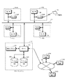
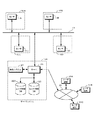
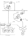
この発明の実施の第1の形態について説明する。図1は、この発明の第1の形態による一例のシステム構成を概略的に示す。このシステムによりサービスの対象となる、例えば所定の施設10A、10B、10C、・・・に対して、センサ装置11A、11B、11C、・・・がそれぞれ配置される。同様に、これらセンサ装置11A、11B、11C、・・・にそれぞれ対応してリーダ12A、12B、12C、・・・が配置される。これらセンサ装置11A、11B、11C、・・・、ならびに、リーダ12A、12B、12C、・・・は、ネットワーク13にそれぞれ接続される。ネットワーク13に対して、サーバシステム14がさらに接続される。
2. First Embodiment of the Invention 2-1-1. About System A first embodiment of the present invention will be described. FIG. 1 schematically shows an example of a system configuration according to the first embodiment of the present invention.
センサ装置11A、11B、11C、・・・は、例えば、撮像素子を有し静止画および/または動画を撮影するようにされたカメラ装置である。センサ装置11A、11B、11C、・・・は、被写体を撮影して得られた静止画データおよび/または動画データを、センサ装置11A、11B、11C、・・・をそれぞれ識別するための識別情報であるセンサIDと、画像データが撮影された時刻を示す時刻情報とに対応付けて出力する。センサ装置11A、11B、11C、・・・から出力された静止画データおよび/または動画データ、ならびに、センサIDは、ネットワーク13を介してサーバシステム14に対して送信される。
The
なお、以下では、静止画データと動画データとを特に区別する必要がある場合を除き、これらを適宜、画像データとして統一的に記述する。 In the following description, unless otherwise required to distinguish between still image data and moving image data, they are described uniformly as image data as appropriate.
リーダ12A、12B、12C、・・・は、所定の記憶媒体からなるユーザ媒体15に記憶された、ユーザを識別するための識別情報であるユーザIDを読み出す。読み出されたユーザIDは、ネットワーク13を介してサーバシステム14に対して送信される。
The
ネットワーク13は、このシステムで閉じたネットワークとしてもよいし、インターネットのようなオープンなネットワークであってもよい。ネットワーク13としてオープンなネットワークを用いる場合には、各センサ装置11A、11B、11C、・・・、各リーダ12A、12B、12C、・・・、ならびに、サーバシステム14との間でやりとりされるデータは、所定の暗号化方式で以て暗号化することが望ましい。
The
サーバシステム14は、例えば、サーバ部20、解析システム部21、センサ情報データベース22およびユーザ情報データベース23を有する。サーバ部20は、このシステムの全体の制御や管理を行う。例えばサーバ部20は、ネットワーク13を介して各センサ装置11A、11B、11C、・・・や各リーダ12A、12B、12C、・・・と通信を行い、各センサ装置11A、11B、11C、・・・や、各リーダ12A、12B、12C、・・・から送信されたデータを受信する。受信されたデータは、センサ情報データベース22やユーザ情報データベース23に所定に格納される。例えば、詳細は後述するが、受信されたデータのうち画像データは、所定の識別情報に関連付けられてセンサ情報データベース22に格納される。
The
解析システム部21は、センサ装置11A、11B、11C、・・・で取得されセンサ情報データベース22に格納された画像データに対して、所定の解析処理(1次解析)を行い、1次解析結果に基づき必要であると判断されれば、当該画像データに対してさらに2次解析処理を行う。
The
サーバシステム14は、サーバ部20によりインターネット30に接続される。インターネット30には、例えば登録ユーザのユーザ端末31A、31B、31C、・・・が接続される。ユーザ端末31A、31B、31C、・・・は、インターネット30による通信が可能であれば特に種類を問わないが、例えばパーソナルコンピュータや、電波を用いてインターネット30との通信が可能とされた携帯端末装置などであって、電子メールの送受信を行うメーラや、ウェブサイトのウェブページを閲覧するためのブラウザなどの、インターネット30を利用するために必要なソフトウェアが搭載されている。サーバ部20は、インターネット30に接続される、登録ユーザのユーザ端末31A、31B、31C、・・・のそれぞれと、インターネット30を介して通信を行うことができる。
The
サーバシステム14が有するセンサ情報データベース22およびユーザ情報データベース23について、概略的に説明する。センサ情報データベース22は、各センサ装置11A、11B、11C、・・・からの画像データを、所定の識別情報と対応付けて格納する。図2は、センサ情報データベース22に格納されるセンサ情報テーブルの一例の構成を示す。この図2の例は、各センサ装置11A、11B、11C、・・・毎に、センサ情報テーブルが設けられる例である。各センサ情報テーブルは、各センサ装置11A、11B、11C、・・・にそれぞれ対応するセンサIDにより識別される。
The
センサ情報テーブルにおいて、画像データは、例えばユニークなデータIDにより識別され、時刻情報およびユーザIDと対応付けられて蓄積的に登録される。画像データは、例えば、実際にはサーバ部20が有する所定のストレージ装置(図示しない)に格納され、センサ情報テーブルには、画像データの格納場所を示すポインタが登録される。時刻情報は、例えば画像データがセンサ装置(例えばセンサ装置11A)で撮影された時刻を示す。また、ユーザIDは、例えば、当該センサ装置に対応するリーダ(例えばリーダ12A)によりユーザ媒体15から読み取られ、サーバシステム14に送信される。
In the sensor information table, image data is identified by, for example, a unique data ID, and is registered in association with time information and a user ID. For example, the image data is actually stored in a predetermined storage device (not shown) included in the
画像データと、時刻情報およびユーザIDとを対応付ける一例の方法として、互いに対応するセンサ装置11A、11B、11C、・・・とリーダ12A、12B、12C、・・・とを連動させる方法が考えられる。すなわち、例えば互いに対応するセンサ装置11Aおよびリーダ12Aにおいて、リーダ12Aによりユーザ媒体15から読み出されたユーザIDを所定に保持する。そして、センサ装置11Aから画像データが出力される際に、保持されているユーザIDを当該画像データに対して対応付けて、サーバシステム14に対して送信する。
As an example of a method for associating image data with time information and a user ID, a method of interlocking
これに限らず、各センサ装置11A、11B、11C、・・・において、画像データの撮影を行った時刻を示す時刻情報を画像データに対応付けて送信すると共に、リーダ12A、12B、12C、・・・においても、ユーザ媒体15から読み出したユーザIDを送信する際に、ユーザ媒体15からの読み出しを行った時刻を示す時刻情報を、当該ユーザIDに対応付けて送信することも考えられる。サーバシステム14において、サーバ部20は、これらの時刻情報に基づき画像データとユーザIDとを対応付けることができる。
In addition to this, in each of the
ユーザ情報データベース23は、例えばユーザ情報テーブルおよび参照情報テーブルを有し、登録されたユーザに関する情報が格納される。図3は、ユーザ情報テーブルの一例の構成を示す。ユーザ情報テーブルにおいて、ユーザIDに対して、当該ユーザの属性情報が関連付けられる。属性情報は、例えば当該ユーザの名前、連絡先などからなる。ユーザの連絡先を示す連絡先情報は、このシステムがインターネットを介してデータを配信するようにされている場合、電子メールアドレスが含まれる。それぞれのユーザ情報は、ユーザIDによって互いに識別可能とされる。ユーザ情報テーブルの情報は、例えばユーザのシステムへの登録などの際に、予め登録される。
The
図4は、参照情報テーブルの一例の構成を示す。参照情報テーブルは、センサ装置11A、11B、11C、・・・により取得されサーバシステム14に送信された画像データに対して2次解析処理を行うか否かを判断するための基準となる参照情報が、登録ユーザのそれぞれについて、ユーザIDに対応付けられて登録される。詳細は後述するが、1次解析処理において、参照情報は、画像データが解析システム部21で所定に処理された処理結果と比較されるので、この処理結果と同じ形式のデータとして形成される。参照情報テーブルの情報は、例えばユーザのシステムへの登録などの際に予め登録される。これに限らず、システムの目的や構成によっては、所定のタイミングで参照情報テーブルに登録するようにもできる。
FIG. 4 shows an example of the configuration of the reference information table. The reference information table serves as a reference for determining whether or not to perform secondary analysis processing on image data acquired by the
参照情報としてどのような種類の情報を用いるかは、システムの目的などに応じて異なる。センサ装置11A、11B、11C、・・・がカメラ装置であって、撮影された静止画および/または動画データが処理対象とされるこの例では、ユーザIDに対応するユーザにおけるある特定の状態の顔を撮影した画像データに基づく情報を参照情報として用いることができる。すなわち、ユーザのある特定の状態の顔を撮影した画像データから顔部分を検出し、検出された顔画像の特徴情報を抽出して数値化する。この顔の特徴情報が数値化された値を、参照情報として用いることができる。
What kind of information is used as the reference information varies depending on the purpose of the system. In this example in which the
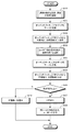
2−1−2.実施の第1の形態による概略的な処理の流れについて
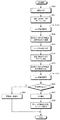
図5は、上述のようなシステムによる、この実施の第1の形態による一例の処理を示すフローチャートである。なお、ユーザ情報データベース23内のユーザ情報テーブルおよび参照情報テーブルに対するデータの登録は、この図5のフローチャートの処理に先立って予めなされており、ユーザは、ユーザIDの記憶されたユーザ媒体15を予め保有しているものとする。
2-1-2. About Schematic Process Flow According to First Embodiment FIG. 5 is a flowchart showing an example of a process according to the first embodiment by the system as described above. Registration of data for the user information table and the reference information table in the
最初のステップS10で、例えば施設10Aにおいて、ユーザによりユーザ媒体15に記憶されたユーザIDをリーダ12Aに読み出させる処理がなされ、また、センサ装置11Aによりユーザを被写体として撮影が行われる。撮影により得られた画像データに対して撮影時刻を示す時刻情報と、センサ装置11Aに対応するセンサIDとが付加されて、リーダ12Aにより読み込まれたユーザIDと共に、ネットワーク13を介してサーバシステム14に受信される。なお、ここでは、センサ装置11Aが出力する画像データは、静止画像データであるものとする。
In the first step S10, for example, in the
サーバシステム14は、受信されたユーザID、画像データおよび時刻情報をセンサ情報データベース22に所定に格納し、画像データについて、解析システム部21に供給して所定の処理を行う(ステップS11)。そして、次のステップS12において、この画像データが所定に処理された結果に基づく1次解析が行われる。例えば、受信されたユーザIDに基づきユーザ情報データベース23内の参照情報テーブルから対応する参照情報が抽出され、抽出された参照情報と、ステップS11による処理結果とが比較される。
The
ステップS12による比較の結果に基づき、ステップS13で閾値判断がなされる。例えば、ステップS12において、参照情報とステップS11による処理結果との差分が所定に算出され、この差分が閾値を超えたか否かがステップS13で判断される。 Based on the result of the comparison in step S12, a threshold value is determined in step S13. For example, in step S12, a difference between the reference information and the processing result in step S11 is calculated in advance, and it is determined in step S13 whether or not this difference has exceeded a threshold value.
若し、ステップS13で差分が閾値を超えたと判断されれば、処理はステップS14に移行される。すなわち、差分が閾値を超えた場合、現在のユーザにおける所定の状態が参照情報で示される状態に対して大きく異なると考えることができ、ステップS14以降で対応する処理がなされる。 If it is determined in step S13 that the difference has exceeded the threshold, the process proceeds to step S14. That is, when the difference exceeds the threshold, it can be considered that the predetermined state of the current user is significantly different from the state indicated by the reference information, and corresponding processing is performed in step S14 and subsequent steps.
ステップS14では、解析システム部21によりさらに解析処理(2次解析処理)が施される。例えば、ステップS14では、現在のユーザにおける所定の状態と参照情報で示される状態とが大きく異なる原因や要因を抽出可能なような解析が、2次解析として行われる。一例として、2次解析として、ステップS11で行った解析をさらに詳細に行うことが考えられる。また、2次解析として、ステップS11で行った解析の解析結果に基づき、他の解析方法を選択することも考えられる。
In step S14, the
次のステップS15では、ステップS14の2次解析処理の結果に基づく通知が、対応するユーザなどに送信される。すなわち、サーバシステム14において、受信されたユーザIDに基づきユーザ情報データベース23内のユーザ情報テーブルが参照され、当該ユーザIDの属性情報から連絡先情報が抽出され、この連絡先情報に示される連絡先に、通知が送信される。連絡先が電子メールアドレスであれば、当該ユーザIDに対応するユーザは、例えばユーザ端末31Aを用いてこの通知にアクセスすることができる。
In the next step S15, a notification based on the result of the secondary analysis process in step S14 is transmitted to the corresponding user or the like. That is, in the
なお、ステップS15でユーザに対して送信される通知の内容は、システムの目的や構成により異なる。例えば、現在のユーザにおける所定の状態と参照情報で示される状態とが大きく異なる原因や要因を示す情報の通知や、当該原因や要因を修正するための情報の通知、警告通知などが考えられる。 Note that the content of the notification transmitted to the user in step S15 varies depending on the purpose and configuration of the system. For example, a notification of information indicating a cause or a factor that greatly differs between a predetermined state of the current user and a state indicated by reference information, a notification of information for correcting the cause or the factor, a warning notification, or the like can be considered.
一方、ステップS13で、差分が閾値を超えていないと判断されれば、処理はステップS16に移行される。この場合には、現在のユーザにおける所定の状態と参照情報で示される状態とが、問題になるほど大きく異ならないと考えることができる。そのため、ステップS16では、特に何も処理を行わないことが考えられる。ステップS16で、対応するユーザなどに対して問題が無い旨を通知することも考えられる。 On the other hand, if it is determined in step S13 that the difference does not exceed the threshold value, the process proceeds to step S16. In this case, it can be considered that the predetermined state of the current user and the state indicated by the reference information are not so different as to cause a problem. Therefore, in step S16, it can be considered that no particular processing is performed. In step S16, it may be possible to notify the corresponding user or the like that there is no problem.
なお、ユーザ情報データベース23内において、ユーザIDに対して他のユーザのユーザIDを関連付けることで、ステップS15やステップS16による通知を対象とされるユーザに送信するのみならず、当該対象ユーザのユーザIDに関連付けられた他のユーザIDに対応するユーザにも送信するようにできる。
In the
2−1−3.補足
上述では、センサ装置11A、11B、11C、・・・が静止画データおよび/または動画データを出力するカメラ装置であるとして説明したが、センサ装置11A、11B、11C、・・・は、ユーザの所定の状態を検出可能な情報が取得できれば、様々な種類の装置を適用することができる。例えば、センサ装置11A、11B、11C、・・・としてカメラ装置を適用した場合であっても、可視光領域の光を撮影対象とするものに限られず、赤外線領域や紫外線領域、X線領域の光を撮影対象とするような装置でもよい。
2-1-3. Supplement: In the above description, the
センサ装置11A、11B、11C、・・・は、カメラ装置やビデオカメラ装置のような画像を出力する装置に限られない。例えば、マイクロフォンを用いて収音された音声を出力するようなオーディオ装置をセンサ装置11A、11B、11C、・・・として用いることも可能である。
The
さらに例えば、所定のコードを含むディジタル信号が変調された電波を受信して復調するようにした受信装置を、センサ装置11A、11B、11C、・・・として用いることも考えられる。この場合、サービスを受けるユーザに対して、ユーザ毎にユニークなコードを変調して送信する送信機を所持させるようにする。
Further, for example, it is conceivable to use, as the
ユーザ媒体15として適用可能な記憶媒体は、様々に考えられる。例えば、合成樹脂製のカード内にIC(Integrated Circuit)チップ、不揮発性メモリおよびアンテナを内蔵させ、リーダ14から発せられる電波により自己発電を行い作動するようにされたカード型記憶媒体を、ユーザ媒体15として適用することができる。また、ユーザが所持する携帯およびデータの送受信が可能な情報機器を、ユーザ媒体15として適用することができる。このような情報機器としては、データの送受信が可能とされた携帯電話端末やPDA(Personal Digital Assistant)などが考えられる。
Various storage media can be used as the
さらに、近年では、携帯電話端末に対して、電話通信機能とは別途にICチップやアンテナ機構、不揮発性メモリを内蔵させ、カード型記憶媒体と同等の機能を持たせた製品も出現している。このような携帯電話端末の、カード型記憶媒体対応機能部分をユーザ媒体15として用いることも可能である。
Furthermore, in recent years, products that have an IC chip, an antenna mechanism, and a non-volatile memory, in addition to the telephone communication function, and a function equivalent to that of a card-type storage medium have appeared. . It is also possible to use the functional part corresponding to the card type storage medium of such a mobile phone terminal as the
さらに、リーダ12A、12B、12C、・・・とユーザ媒体15との間のデータ通信は、無線によるものに限られず、有線、例えばコネクタを介した電気的接触を用いて行うようにしてもよい。この場合、ユーザ媒体15は、不揮発性メモリとインターフェイスとで構成することができ、所謂USB(Universal Serial Bus)メモリ、コンパクトフラッシュメモリ(コンパクトフラッシュは登録商標)、スマートメディアなどを適用することができる。
Further, the data communication between the
さらにまた、ユーザ媒体15は、磁気ディスクや磁気カード、光磁気ディスク、光ディスクといった、書き換え可能な記録媒体としてもよい。この場合、リーダ12A、12B、12C、・・・は、対応するドライブ装置を備える。
Furthermore, the
さらに、ユーザ媒体15は、物理的な変形を以てデータを記録するようなものでもよい。例えば、紙やプラスチック板などに穴を穿ち、データを記録することが考えられる。ユーザIDや日時の情報を記録するのみであれば、このような記録方法でも十分対応可能である。この場合、リーダ12A、12B、12C、・・・は、光学的手法や、電気的な接触を以てデータの読み取りを行う。
Further, the
また、ユーザ媒体15として、印刷媒体を用いることができる。例えば、データをバーコードやQRコード(Quick Response Code)といった所定のコードに変換し、紙やその他の所定の印刷媒体に印刷することで、データの記録を行う。リーダ12A、12B、12C、・・・は、例えば印刷された情報を光を用いて読み取る読み取り装置を備える。
A print medium can be used as the
2−2.実施の第1の形態の第1の応用例について
次に、この発明の実施の第1の形態の第1の応用例について説明する。第1の応用例は、この実施の第1の形態を、化粧方法をアドバイスするような化粧サポートシステムに適用する例である。
2-2. First Application Example of First Embodiment Next, a first application example of the first embodiment of the present invention will be described. The first application example is an example in which the first embodiment is applied to a makeup support system that advises a makeup method.
2−2−1.システムの概要
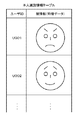
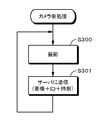
この化粧サポートシステムについて概略的に説明する。図6は、この化粧サポートシステムの概要を説明するための一例の流れを示すフローチャートである。先ず、ユーザに対して、メイクアップアーティストなどの手により最適と考えられるメイクアップ(理想メイクと呼ぶ)を施す(ステップS20)。そして、この理想メイクが施された顔を所定に撮影し、撮影により得られた画像データをサーバシステムに送信する(ステップS21)。サーバシステム側では、送信されたこの理想メイクによる画像データに基づき、化粧の状態を判断するのに適切な特徴に特化させて顔の特徴情報を抽出し、抽出された顔の特徴情報を、ユーザの参照情報としてユーザ情報データベースに登録する(ステップS22)。このとき、理想メイクを施すのに用いた化粧品を示す情報を、当該参照情報に対応付けて所定にデータベースに登録するとよい。
2-2-1. Outline of system The makeup support system will be schematically described. FIG. 6 is a flowchart showing an exemplary flow for explaining the outline of the makeup support system. First, makeup (referred to as ideal makeup) considered to be optimal is applied to the user by the hands of a makeup artist or the like (step S20). Then, the face with the ideal makeup is photographed in a predetermined manner, and image data obtained by photographing is transmitted to the server system (step S21). On the server system side, based on the transmitted image data of the ideal makeup, the facial feature information is extracted by specializing in features suitable for judging the makeup state, and the extracted facial feature information is It is registered in the user information database as user reference information (step S22). At this time, information indicating the cosmetic used for applying the ideal makeup may be registered in a predetermined database in association with the reference information.
一方、ユーザは、後に、例えば自宅において自分でメイクアップ(自己メイクと呼ぶ)を施し(ステップS23)、自己メイクが施された顔を撮影する。そして、撮影により得られたこの自己メイクによる画像データをサーバシステムに送信する(ステップS24)。サーバシステム側では、ユーザから送信された画像データに所定の処理を施して、顔の、化粧の状態を示す特徴に特化した特徴情報を抽出し、この抽出されたこの特徴情報に対する1次解析処理を行う。1次解析処理は、例えば、当該ユーザの参照情報として登録されている特徴情報とを比較することで行う(ステップS25)。1次解析による比較の結果、両者の差が所定以上であるとされれば(ステップS26)、ユーザの化粧方法に何らかの問題があると考えることができる。そこで、サーバシステム側では、ユーザから送信された画像データおよび/または当該画像データを解析した解析結果に対して、問題部分を抽出可能なように2次解析処理を施す(ステップS27)。 On the other hand, the user later performs makeup (referred to as self-makeup) himself at home, for example (step S23), and photographs the face on which self-makeup has been performed. Then, this self-makeup image data obtained by photographing is transmitted to the server system (step S24). On the server system side, the image data transmitted from the user is subjected to predetermined processing to extract feature information specialized for the facial feature indicating the makeup state, and a primary analysis is performed on the extracted feature information. Process. The primary analysis process is performed, for example, by comparing with feature information registered as reference information of the user (step S25). As a result of the comparison by the primary analysis, if the difference between the two is determined to be greater than or equal to a predetermined value (step S26), it can be considered that there is some problem in the user's makeup method. Therefore, the server system side performs secondary analysis processing on the image data transmitted from the user and / or the analysis result obtained by analyzing the image data so that the problem part can be extracted (step S27).
サーバシステム側は、2次解析処理の結果に基づき、化粧方法に対してアドバイスを行うアドバイス情報を作成する。作成されたアドバイス情報は、当該ユーザに対して送信される(ステップS28)。このとき、アドバイス情報に対応して、お勧めの化粧品などを示す情報を当該アドバイス情報に付加して送信することができる。ユーザは、自宅に居ながらにして、自己のメイクアップを理想メイクに近付ける方法を取得することができると共に、必要な化粧品などの情報を得ることができる。 The server system side creates advice information for giving advice to the makeup method based on the result of the secondary analysis processing. The created advice information is transmitted to the user (step S28). At this time, corresponding to the advice information, information indicating recommended cosmetics or the like can be added to the advice information and transmitted. While staying at home, the user can obtain a method for bringing his / her make-up closer to the ideal make-up, and can obtain information such as necessary cosmetics.
なお、ステップS26で、差が所定未満であるとされた場合には、サーバシステム側からユーザに対して、現在のメイクアップ方法に問題が無い旨を示す通知が送信される(ステップS29)。このとき、参照情報に対応付けられて所定にデータベースに登録された、理想メイクを施す際に用いた化粧品の購入情報などを、当該通知に付加して送信することが考えられる。 If it is determined in step S26 that the difference is less than the predetermined value, a notification indicating that there is no problem in the current makeup method is transmitted from the server system side to the user (step S29). At this time, it is conceivable that the purchase information of cosmetics used when applying the ideal makeup, which is registered in the database in association with the reference information, is added to the notification and transmitted.
2−2−2.第1の応用例に適用可能なシステムについて
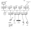
図7は、この実施の第1の形態の第1の応用例に適用可能な一例のシステムを概略的に示す。図7に例示する第1の応用例に適用可能なシステムは、基本的には、図1を用いて上述した、実施の第1の形態に適用可能なシステムと同様な構成を有する。カメラ装置101Aおよびリーダ102Aが施設100Aに配置され、ネットワーク103に接続される。施設100Aは、例えばデパートの化粧品コーナや化粧品メーカなどが主催するメイクアップ教室といった、メイクアップアーティストといったメイクアップのプロフェッショナルがユーザに対してメイクアップを施すようにされた場所である。同様に、カメラ装置101Bおよびリーダ102Bが、例えばユーザの自宅100Bに配置され、ネットワーク103に接続される。
2-2-2. About System Applicable to First Application Example FIG. 7 schematically illustrates an example system applicable to the first application example of the first embodiment. The system applicable to the first application example illustrated in FIG. 7 basically has the same configuration as the system applicable to the first embodiment described above with reference to FIG. A
カメラ装置101Aおよびカメラ装置101Bは、被写体を撮影し、静止画像データを出力する。また、カメラ装置101Aおよび101Bは、静止画像データと共に、当該静止画像データを撮影した時刻を示す時刻情報と、カメラ装置101Aおよび101Bのそれぞれを識別するためのセンサIDとを、当該静止画像データに対応付けて出力する。なお、施設100Aに対して、動画像データを出力するビデオカメラ装置をさらに設けるとよい。カメラ装置101Aにおいて動画像データ出力し、この動画像データから静止画像データを所定に取り出しても良い。
The
リーダ102Aおよび102Bは、図示されないユーザ媒体15に記憶されたユーザIDを読み出す。ユーザ媒体15は、既に述べたように様々な種類のものを適用可能であるが、この第1の応用例では、ユーザ媒体15は、上述した、合成樹脂製のカード内に不揮発性メモリ、送受信部および発電部を有するカード型記憶媒体であるものとする。ユーザ媒体15は、予めユーザIDが記憶され対応するユーザに渡されているものとする。
The readers 102A and 102B read the user ID stored in the user medium 15 (not shown). As described above, various types of
ここでは、カメラ装置101Aから出力される画像データと、リーダ102Aで読み出されたユーザIDとが所定に対応付けられて、ネットワーク103に対して送信されるものとする。例えば、ユーザ媒体15から読み出されたユーザIDを、次にリーダ102Aにユーザ媒体15が読み込まれるか、リーダ102Aに対して保持されるユーザIDの消去操作がなされるまで、リーダ102Aに保持することが考えられる。カメラ装置101Aから出力される画像データに対して、リーダ102Aに保持されるユーザIDを所定に対応付ける。これは、カメラ装置101Bおよびリーダ102Bについても同様とする。
Here, it is assumed that the image data output from the
なお、この第1の応用例において、ユーザIDは、ユーザ媒体15からリーダ102Aにより読み出されるのに限らない。例えば、リーダ102Aをキーボードなど所定の入力手段を設けた入力装置とし、ユーザがマニュアルでユーザIDを入力するようにしてもよい。
In the first application example, the user ID is not limited to being read from the
ネットワーク103は、このシステムで閉じたネットワークとしてもよいし、インターネットのようなオープンなネットワークであってもよい。ネットワーク103としてオープンなネットワークを用いる場合には、各カメラ装置101Aおよび101B、各リーダ102Aおよび102B、ならびに、サーバシステム104との間でやりとりされるデータは、所定の暗号化方式で以て暗号化することが望ましい。
The
なお、図7では、ネットワーク103に対して接続されるカメラ装置およびリーダが配置される施設などが、施設100Aおよびユーザの自宅100Bのみとなっているが、実際には、さらに多数の施設等に設けられたカメラ装置やリーダが、ネットワーク103に対して識別可能に接続される。
In FIG. 7, the facility where the camera device and the reader connected to the
サーバシステム104は、図1を用いて説明したサーバシステム14に対応するもので、例えばサーバ部110、解析システム部111、センサ情報データベース112およびユーザ情報データベース113を有し、この第1の応用例では、さらに、化粧品データベース114を有する。サーバ部110は、このシステムの全体の制御や管理を行う。例えば、サーバ部110は、ネットワーク103を介してカメラ装置101Aおよびリーダ102Aと通信を行い、カメラ装置101Aおよびリーダ102Aから互いに対応付けられて送信された画像データおよびユーザIDを受信し、センサ情報データベース112に所定に格納する。カメラ装置101Bおよびリーダ102Bから出力されるデータに関しても、同様である。
The
解析システム部111は、カメラ装置101Aおよび101Bで取得されセンサ情報データベース112に格納された画像データに対して、一例を後述するような1次解析処理を行う。さらに、1次解析の解析結果に基づき閾値判断を行い、判断結果に応じて一例を後述するような2次解析を行う。
The
サーバシステム104は、サーバ部110によりインターネット130に接続される。インターネット130には、例えばユーザが自宅100Bなどで利用可能な、パーソナルコンピュータなどによるユーザ端末131が接続される。なお、この図7では、インターネット130に接続されるユーザ端末がユーザ端末131のみとなっているが、実際には、さらに多数のユーザ端末の接続が可能である。
The
インターネット130には、さらに、インターネット130に向けてウェブページ公開などウェブサービスを提供するサーバであるウェブサーバ132が接続される。サーバシステム104は、インターネット130を介してウェブサーバ132と通信を行い、ウェブサーバ132に対してファイルのアップロードなどを行うことができる。
Further connected to the
なお、上述では、ユーザの自宅100Bに配置されるカメラ装置101Bがネットワーク103に接続されているように説明したが、これはこの例に限定されない。例えば、カメラ装置101Bがパーソナルコンピュータであるユーザ端末131に接続されるものとし、カメラ装置101Bによる撮影の制御をユーザ端末131にて行い、カメラ装置101Bから出力されたビデオデータをユーザ端末131からインターネット130を介してサーバシステム104に送信するようにしてもよい。
In the above description, the camera device 101B disposed in the user's home 100B has been described as being connected to the
センサ情報データベース112およびユーザ情報データベース113の構成について、概略的に説明する。センサ情報データベース112の構成は、基本的には、図2を用いて説明したセンサ情報データベース22と同一である。なお、施設100Aにおいてビデオカメラ装置が設けられ、動画像を撮影するようにしている場合、ビデオカメラ装置は、動画像データを所定に圧縮符号化してネットワーク103に対して送信し、サーバ部110は、圧縮符号化され供給されたこのビデオデータを所定に格納する。そして、データを識別するデータIDと、圧縮符号化されたビデオデータの実データの格納場所を示す情報とを対応付けて、センサ情報データベース112内のセンサ情報テーブルに登録する。
The configurations of the
ユーザ情報データベース113は、ユーザ情報が登録されるユーザ情報テーブルと、参照情報テーブルとを有する。図8は、ユーザ情報データベース113内のユーザ情報テーブルの一例の構成を示す。ユーザ情報テーブルは、ユーザを識別するユーザID毎に、ユーザIDが対応するユーザの属性情報と、当該ユーザの化粧に関する情報とが登録される。ユーザの属性情報は、例えば、そのユーザの名前、年齢、連絡先(電子メールアドレス)といった、ユーザを表す情報からなる。化粧情報は、そのユーザの化粧に関連する情報であって、肌のタイプ(乾燥肌か脂性か、きめが細かいか粗いか、地肌の色など)、化粧の好み(全体的に白っぽく、全体的に浅黒く、など)、普段使用している化粧品の品番などの情報からなる。これらの情報は、例えば、ユーザがこのシステムの利用を開始する際に設定される。参照情報テーブルの構成については、後述する。
The
このような構成のシステムにおいて、図6を用いて説明した流れに従い、先ずユーザは、施設100Aでメイクアップアーティストなどに、最適と思われるメイクアップ(理想メイク)を施してもらう(ステップS20)。また、ユーザは、リーダ102Aにユーザ媒体15に記憶されるユーザIDを読み取らせると共に、理想メイクが施された顔をカメラ装置101Aにより撮影させる。顔の撮影は、例えば、立体画像を構成可能なように、顔の正面、側面、上方といったように、複数の方向からなされる。メイクアップの様子をビデオカメラで撮影し、動画像データとして出力することもできる。また、後に画像補正が可能なように、色、濃淡、明るさなどの基準となる被写体が、ユーザの顔と同一の画像データ中に含まれるように撮影される。撮影で得られた複数の画像データは、それぞれ撮影された時刻を示す時刻情報と、カメラ装置101Aを識別するセンサIDと、ユーザIDとが付加されて、ネットワーク103を介してサーバシステム104に送信される(ステップS21)。
In the system configured as described above, according to the flow described with reference to FIG. 6, first, the user asks a makeup artist or the like to make up makeup (ideal makeup) at the facility 100A (step S20). Further, the user causes the reader 102A to read the user ID stored in the
サーバシステム104は、これら画像データと、当該画像データに付加された時刻情報、センサIDおよびユーザIDとをサーバ部110に供給する。サーバ部110は、センサ情報データベース112のセンサIDが対応するセンサ情報テーブルに対し、画像データ、時刻情報およびユーザIDを所定に対応付けて格納する。センサ情報データベース112に格納された画像データは、ユーザIDなどに基づきサーバ部20に読み出され、解析システム部111に供給される。解析システム部111は、供給された画像データに対して所定の処理を施し、処理結果に基づき当該画像データに対応する参照情報を生成する。参照情報は、参照情報を識別するための参照情報IDを付加され、関連する他の情報と対応付けられて、ユーザ情報データベース113内の参照情報テーブルに所定に登録される(ステップS22)。
The
ユーザは、後に、例えばユーザの自宅100Bで、理想メイクに倣って自分でメイクアップ(自己メイク)を行う(ステップS23)。また、ユーザは、リーダ102Bにユーザ媒体15に記憶されるユーザIDを読み出させる。そして、ユーザは、自己メイクが施された顔をカメラ装置101Bで撮影する。ユーザ側では、立体画像を構成可能に撮影を行う必要はなく、例えば顔の正面からのみの撮影が行われる。このときにも、後に画像補正が可能なように、色、濃淡、明るさなどの基準となる被写体が、ユーザの顔と同一の画像データ中に含まれるように撮影される。撮影で得られた複数の画像データは、それぞれ撮影された時刻を示す時刻情報と、カメラ装置101Aを識別するセンサIDと、ユーザIDとが付加されて、ネットワーク103を介してサーバシステム104に送信される(ステップS24)。
The user later performs makeup (self-makeup) himself following the ideal makeup, for example, at the user's home 100B (step S23). In addition, the user causes the reader 102B to read the user ID stored in the
サーバシステム104は、これら自己メイクによる画像データと、当該画像データに付加された時刻情報、センサIDおよびユーザIDとをサーバ部110に供給する。サーバ部110は、センサ情報データベース112のセンサIDが対応するセンサ情報テーブルに対し、画像データ、時刻情報およびユーザIDを所定に対応付けて格納する。センサ情報データベース112に格納された画像データは、ユーザIDなどに基づきサーバ部20に読み出され、解析システム部111に供給される。解析システム部111は、供給された画像データに対して所定の処理を施す。サーバ部110は、供給されたユーザIDに基づきユーザ情報データベース113内の参照情報テーブルから対応する参照情報を抽出し、参照情報と、自己メイクによる画像データに基づく処理結果とを比較し、1次解析を行う(ステップS25)。
The
1次解析の結果、参照情報と自己メイクによる画像データに基づく処理結果との差が所定以上あれば(ステップS26)、サーバ部110は、自己メイクによる画像データに基づき2次解析処理を行う(ステップS27)。そして、2次解析結果に基づきアドバイス情報を作成し、ユーザに対して送信する。例えば、サーバ部110は、ユーザIDに基づきユーザ情報データベース113内のユーザ情報テーブルを検索し、当該ユーザIDに対応付けられた電子メールアドレスを取得し、取得された電子メールアドレスに対して、アドバイス情報が記述または添付された電子メールを送信する。
As a result of the primary analysis, if the difference between the reference information and the processing result based on the self-make image data is greater than or equal to a predetermined value (step S26), the
ユーザは、サーバ部110から送信された、アドバイス情報が添付された電子メールを、例えばユーザの自宅100Bにおいてユーザ端末131を用いて受信することで、アドバイス情報に基づきより理想メイクに近い自己メイクを行うことが可能となる。
The user receives the e-mail attached with the advice information transmitted from the
ここで、アドバイス情報と共に、当該ユーザの参照情報に対応する画像データをユーザに対して送信することが考えられる。すなわち、アドバイス情報と当該画像データとを一纏めにパッケージングし、このパッケージデータを電子メールに添付して送信する。ユーザは、この電子メールをユーザ端末131で受信して、画像データを表示させながらアドバイス情報を参照することで、理想メイクによる画像を見ながらアドバイス情報に従いメイクアップを行うことができ、より容易に、理想メイクに近い自己メイクを行うことができる。
Here, it is conceivable to transmit image data corresponding to the reference information of the user together with the advice information to the user. That is, the advice information and the image data are packaged together, and the package data is attached to an electronic mail and transmitted. The user receives this e-mail at the
さらに、サーバ部110は、アドバイス情報に応じた広告を、アドバイス情報および理想メイクによる画像データとパッケージングしてユーザに送信することができる。例えば、サーバ部110は、2次解析結果に基づき、1次解析の結果として得られる差分を所定以下とすると思われる化粧品を、化粧品データベース114から検索することが考えられる。これに限らず、ステップS20による理想メイク時に用いた化粧品の情報を化粧品データベース114から検索してもよい。サーバ部110は、化粧品データベース114から検索された化粧品の情報に基づく広告と、アドバイス情報と、理想メイクによる画像データとを一纏めにしてパッケージングし、パッケージデータとしてユーザに送信する。これによれば、ユーザは、自分に合った化粧品の情報を即座に入手することができる。
Further, the
図9は、パッケージデータの一例の構成を示す。パッケージデータ140は、例えば、互いに対応するメタデータ141、個別データ142、142、・・・および付加情報143が一纏めにされたもので、一例として、これらのデータそれぞれをファイルとして構成し、アーカイブして1のファイルとすることが考えられる。1のフォルダ内にこれらのファイルを纏めて格納し、フォルダ自体をパッケージデータ140と見做すことも考えられる。
FIG. 9 shows an exemplary configuration of package data. The
メタデータ141は、パッケージングされたパッケージデータ140自体の属性であって、パッケージされたデータの内容を統括的に示す情報からなる。例えば、ユーザが理想メイクを行った施設100Aなどを識別するためのID情報をメタデータ141として格納することが考えられる。個別データ142、142、・・・は、例えば、参照情報に対応する画像データ、アドバイス情報、広告情報がそれぞれ格納される。付加情報143は、所定の付加情報を格納することができ、例えばユーザが理想メイクを行った日時、メイクアップを担当したメイクアップアーティスト名、メイクアップを行った施設100Aの名前などを付加情報143として格納することが考えられる。
The
上述では、パッケージデータ140に対してアドバイス情報、理想メイクによる画像データおよび広告情報を格納したが、これはこの例に限定されない。施設100Aにおいてメイクアップの様子を動画像データとして撮影している場合には、この動画像データをさらにパッケージデータ140に格納することができる。サーバ部110は、センサ情報データベース112から所定に動画像データを取り出して、パッケージデータ140に個別データとしてパッケージングして格納する。
In the above description, advice information, image data by ideal makeup, and advertisement information are stored in the
なお、パッケージデータ140に個別データとして含まれる動画像データは、所謂ストリーミング配信を行うと、配信先における閲覧時の負担が減り、好ましい。ストリーミング配信は、圧縮された動画像データおよび音声データを所定単位毎に配信し、受信側でバッファに溜め込み伸長しながら続きのデータを受信してバッファに蓄えるようにして、動画像データや音声データなどのストリームデータをダウンロードしながら再生できるようにしたものである。
Note that moving image data included as individual data in the
2−2−3.第1の応用例による解析処理の例について
次に、この実施の第1の形態の第1の応用例に適用可能な1次解析処理および2次解析処理の例について説明する。先ず、1次解析処理の例について説明する。1次解析処理は、例えば、顔における複数の所定ポイントを計測ポイントとして設定し、理想メイクを施した顔と自己メイクを施した顔とに対し、各々の計測ポイントで所定の計測を行い、理想メイクを施した顔について計測された値と、自己メイクを施した顔について計測された値とを比較し、差分を計算する。そして、この差分を、所定の閾値と比較することが考えられる。
2-2-3. Example of Analysis Processing According to First Application Example Next, examples of primary analysis processing and secondary analysis processing applicable to the first application example of the first embodiment will be described. First, an example of the primary analysis process will be described. In the primary analysis process, for example, a plurality of predetermined points on the face are set as measurement points, and predetermined measurement is performed at each measurement point on a face subjected to ideal makeup and a face subjected to self-makeup. A difference is calculated by comparing the value measured for the face with makeup and the value measured for the face with self-makeup. It is conceivable to compare this difference with a predetermined threshold.
図10を用いて、計測ポイントの例について説明する。例えば、サーバシステム104は、ユーザが施設100Aにおいて理想メイクを施された際に撮影された画像データに基づき、計測ポイントを設定する。先ず、顔150を正面から撮影した画像データに基づき、顔の輪郭152を特定すると共に、頭髪の輪郭151を特定する。特定された顔の輪郭152に基づき、顔150の内部の計測ポイントの位置を特定する。
An example of measurement points will be described with reference to FIG. For example, the
顔150の内部の計測ポイントとして、左右の眉153Aおよび153B、左右の目154Aおよび154B、ならびに、口唇155が考えられる。これら眉153Aおよび153B、目154Aおよび154B、ならびに、口唇155について、位置および形状が計測される。口唇155の形状に関しては、色を計測し色の変化に基づき判断することが考えられる。立体画像に基づき口唇155の形状を判断することもできる。眉153Aおよび153Bについては、色も計測される。目154Aおよび154Bについては、さらに詳細に、アイライン、睫などの色および形状が計測される。
As measurement points inside the
顔150の内部の計測ポイントとして、さらに、化粧の際に注目される所定の位置156A〜156Jを特定することが考えられる。一例として、額の中央の位置156A、鼻筋に相当する位置156Dおよび位置156G、左右の瞼の位置156Bおよび156C、左右の頬骨の位置156Eおよび156F、左右の頬の位置156Hおよび156I、ならびに、顎の位置156Jが考えられる。これらの位置156A〜156Jについて、位置および色が計測される。
As measurement points inside the
なお、これら位置156A〜156Jのうち、特に頬骨の位置156Eおよび156Fや、鼻の頂点の位置156G、顎の位置156Jなどは、理想メイク後に複数の方向から撮影された画像データに基づき構成される、顔の立体画像を用いることで特定できると考えられる。
Of these positions 156A to 156J,
また、図示しないが、顔150の内部の計測ポイントとして、例えば所定の2点を結ぶ線を特定することが考えられる。この所定の2点を結ぶ線により、色のグラデーションが計測される。この後羅デーションを計測するための所定の2点は、例えば目の近辺や、頬骨や頬の近辺に設定することが考えられる。
Further, although not shown, as a measurement point inside the
理想メイクによる画像データについて、これらの計測ポイントの計測値に基づきそれぞれ評価値を求める。眉、目、口唇などの形状データに関しては、これら眉、目、口唇に関して様々な形状が数値化されて登録された形状辞書を用意し、顔から計測された計測値と形状辞書に登録された値とを比較して差分を求め、差分に基づき評価値を求めることが考えられる。色に関しては、画像データから得られる3原色の値そのものを評価値として用いることが考えられる。これに限らず、3原色の値をCIE(commission internationale de l'eclairage)により規定される色度座標(x,y,Y)などに変換して、評価値として用いることも考えられる。グラデーションに関しては、所定の2点を結ぶ線上の複数点の色を計測することが考えられる。 Evaluation values are obtained for the image data based on the ideal makeup based on the measurement values at these measurement points. For shape data of eyebrows, eyes, lips, etc., a shape dictionary in which various shapes for these eyebrows, eyes, and lips are digitized and registered is prepared, and the measured values measured from the face and registered in the shape dictionary It can be considered that a difference is obtained by comparing the value and an evaluation value is obtained based on the difference. Regarding colors, it is conceivable to use the values of the three primary colors themselves obtained from the image data as evaluation values. Not limited to this, the values of the three primary colors may be converted into chromaticity coordinates (x, y, Y) defined by CIE (commission internationale de l'eclairage) and used as evaluation values. Regarding gradation, it is conceivable to measure the colors of a plurality of points on a line connecting two predetermined points.
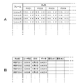
このようにして、理想メイクによる画像データから求められた各計測ポイントの位置情報と、評価値とが参照情報として、参照情報テーブルに登録される。図11は、参照情報テーブルの構成例を示す。ここでは、図11A〜図11Dに例示されるように、参照情報テーブルを複数のテーブルから構成している。参照情報テーブルの構成はこれに限らず、複数のテーブルを1つに纏めてもよいし、さらに分割することも考えられる。 In this way, the position information of each measurement point obtained from the image data by ideal makeup and the evaluation value are registered in the reference information table as reference information. FIG. 11 shows a configuration example of the reference information table. Here, as illustrated in FIGS. 11A to 11D, the reference information table is composed of a plurality of tables. The configuration of the reference information table is not limited to this, and a plurality of tables may be combined into one, or further divided.
図11Aは、各計測ポイントを定義する定義テーブルの一例の構成を示す。この定義テーブルは、例えば参照情報毎に設けられ、計測ポイントを識別する識別情報PoIDに対して、位置情報と計測ポイントの種類が対応付けられて格納される。計測ポイントが複数の位置情報を用いて定義される場合、当該複数の位置情報を列挙することが考えられる。種類は、色、形状など、当該計測ポイントで計測されるデータの種類を示す。 FIG. 11A shows an example of a definition table that defines each measurement point. This definition table is provided for each reference information, for example, and stores the position information and the types of measurement points in association with the identification information PoID for identifying the measurement points. When a measurement point is defined using a plurality of position information, it is conceivable to list the plurality of position information. The type indicates the type of data measured at the measurement point, such as color and shape.
図11Bは、各計測ポイントにおける評価値が、参照情報毎に格納される評価値テーブルの一例の構成を示す。評価値の代わりに各計測ポイントにおける計測値を格納してもよい。評価値は、解析処理の際に計測値から求めるようにする。 FIG. 11B shows a configuration of an example of an evaluation value table in which evaluation values at each measurement point are stored for each reference information. The measurement value at each measurement point may be stored instead of the evaluation value. The evaluation value is obtained from the measured value during the analysis process.
図11Cは、各参照情報における画像データが格納される画像データテーブルの一例の構成を示す。各参照情報毎に、ユーザを複数の方向から撮影した画像のそれぞれと、これら複数の画像から形成された立体画像とが格納される。なお、実際には、画像データそのものは、サーバ部110が有する所定のストレージ装置(図示しない)に格納され、画像データテーブルに対してこれらの画像データの格納場所を示すポインタが登録される。
FIG. 11C shows a configuration of an example of an image data table in which image data in each reference information is stored. For each reference information, each of images obtained by photographing the user from a plurality of directions and a stereoscopic image formed from the plurality of images are stored. Actually, the image data itself is stored in a predetermined storage device (not shown) included in the
図11Dは、参照情報毎に、属性情報が格納される属性情報テーブルの一例の構成を示す。例えば、参照情報毎に、対応するユーザID、取得された日付、任意の説明、施設100Aの名称や施設100Aにおけるユーザの担当者などを登録することが考えられる。 FIG. 11D shows a configuration of an example of an attribute information table in which attribute information is stored for each reference information. For example, for each reference information, it may be possible to register a corresponding user ID, an acquired date, an arbitrary description, a name of the facility 100A, a person in charge of the user at the facility 100A, and the like.
1次解析は、一例として次のようにして行うことが考えられる。自己メイクによる画像データに対して、参照情報に基づき各計測ポイントの位置を求め、求められた各計測ポイントの位置において、参照情報を求める際に行ったのと同様の計測を行い、各計測結果に基づき評価値を求める。そして、参照情報について求められた各評価値と、自己メイクによる画像データに基づき求められた各評価値とに対し、計測ポイント毎に、計測ポイントに応じた重み付けをそれぞれ所定に行い、重み付けされた評価値に関し、対応する評価値の組それぞれについて差分の絶対値を計算する。評価値の組それぞれについて計算された差分の絶対値を加算して、加算結果を所定の閾値と比較する。加算結果が閾値よりも大きいと判断されれば(図6のステップS26)、2次解析を行う。 The primary analysis may be performed as follows as an example. For the image data by self-make, the position of each measurement point is obtained based on the reference information, and at the position of each obtained measurement point, the same measurement as that performed when obtaining the reference information is performed. The evaluation value is obtained based on Then, for each measurement point, each evaluation value obtained for the reference information and each evaluation value obtained based on the image data by self-make is weighted according to the measurement point, and weighted. For the evaluation value, the absolute value of the difference is calculated for each corresponding set of evaluation values. The absolute values of the differences calculated for each set of evaluation values are added, and the addition result is compared with a predetermined threshold value. If it is determined that the addition result is larger than the threshold value (step S26 in FIG. 6), secondary analysis is performed.
2次解析は、一例として次のようにして行うことが考えられる。先ず、1次解析の際に計算された、各評価値の組毎の差分について、計測ポイント単位で所定にソートし、差分が所定以上の計測ポイントについて、差分が大きい順に、差分の内容を解析する。解析は、計測ポイントの種類および計測内容に応じてなされる。例えば、形状の計測値、すなわち眉、目(睫、アイライン)、口唇(口紅の境界)などの場合は、理想メイクと自己メイクとで輪郭の位置になどにずれが生じていると考えられるので、ずれの大きさや方向が解析される。色の計測値、すなわち口唇や、顔150の内部の所定位置156A〜156J、2点間のグラデーションなどの場合は、色差の解析や、色度座標上でどの方向にずれているかなどが解析される。
The secondary analysis may be performed as follows as an example. First, the difference for each set of evaluation values calculated at the time of the primary analysis is sorted in units of measurement points, and the contents of the differences are analyzed in descending order for the measurement points having a difference greater than or equal to a predetermined value. To do. The analysis is performed according to the type of measurement point and the measurement content. For example, in the case of a shape measurement value, that is, eyebrows, eyes (eyelids, eyelines), lips (boundary of lipstick), it is considered that there is a deviation in the position of the contour between ideal makeup and self makeup. Therefore, the magnitude and direction of the deviation are analyzed. In the case of a color measurement value, that is, a lip or a gradation between two predetermined positions 156A to 156J inside the
2次解析結果に基づき、ユーザに対して化粧のアドバイスを行うアドバイス情報を生成し、ユーザに提示するとよい。サーバシステム104において、例えば2次解析を行った計測ポイント毎、評価値の差分情報の予測される解析結果毎に、アドバイス用のテキストデータを予め用意する。そして、実際の2次解析の結果に基づき、このアドバイス用のテキストデータを所定に組み合わせて1のテキストデータとし、これを、ユーザに対する全体的な化粧のアドバイス情報として提示する。アドバイス情報は、例えばパッケージデータ140に含めてユーザに提供される。
Based on the secondary analysis result, advice information for giving makeup advice to the user may be generated and presented to the user. In the
上述では、アドバイス情報などを電子メールに添付して送信するように説明したが、これはこの例に限定されない。例えば、アドバイス情報、理想メイクによる画像データおよび広告情報を、ウェブサイト上のウェブページとして、インターネット130上で閲覧可能としてユーザに提示することが考えられる。
In the above description, the advice information and the like are described as being attached to the e-mail, but this is not limited to this example. For example, it is conceivable that advice information, image data based on ideal makeup, and advertisement information are presented to a user as a web page on a website so as to be viewable on the
一例として、サーバ部110に対し、インターネット130上のURL(Uniform Resource Locator)を定義可能なストレージ装置を設け、アドバイス情報、理想メイクによる画像データおよび広告情報を一纏めにしたパッケージデータ140をこのストレージ装置に格納する。この場合には、パッケージデータ140は、例えばアドバイス情報、理想メイクによる画像データが格納されるフォルダである。パッケージデータ140に格納される画像データには、所定のURLが定義される。
As an example, a storage device capable of defining a URL (Uniform Resource Locator) on the
サーバ部110は、HTML(Hyper Text Markup Language)やXML(Extensible Markup Language)など、インターネット130上のウェブページとして提示可能な書式を用いて、ストレージ装置に保持されたパッケージデータ140に含まれる画像データのリンク情報やレイアウト情報、アドバイス情報に基づくテキストデータ、広告情報に基づくリンク情報などを記述したファイル(以降、ウェブファイルと呼ぶ)を作成する。広告情報に基づくリンク情報は、例えば広告情報に示される化粧品を販売するウェブページへのリンク情報である。このウェブファイルを、インターネット130上のウェブサーバ132に転送する。
The
ウェブサーバ132は、このウェブファイルに対してURLを定義し、インターネット130上で閲覧可能とする。ユーザは、インターネット130に接続されたユーザ端末131を用いて当該URLにアクセスすることで、パッケージデータ140に含まれる画像データや、アドバイス情報、広告情報を閲覧可能とされる。
The
一例として、サーバ部110は、ウェブサーバ132に対してウェブファイルを転送すると共に、ユーザに対して、当該ウェブファイルがインターネット130に対して閲覧可能とされていることを通知する。より具体的には、サーバ部110は、ユーザ情報データベース113内のユーザ情報テーブルを検索し、ユーザの電子メールアドレスを取得する。そして、サーバ部110は、当該ウェブファイルのURLを所定に記述した電子メールを作成し、取得された電子メールアドレスに宛てて送信する。この電子メールを受信したユーザは、電子メールの記述に基づき当該URLにアクセスする。
As an example, the
図12は、パッケージデータ140に含まれる画像データ、アドバイス情報、広告情報を閲覧させるウェブページの一例の画面構成を示す。ウェブページは、一般的には、ユーザ端末131に搭載されるブラウザと呼ばれるソフトウェアで表示などがなされる。ブラウザは、例えば入力されたURLに従いインターネット130の上のファイルにアクセスする。アクセスしたファイルが例えばHTML形式といった所定の形式で記述されていれば、ファイルの記述に従い、テキストデータの表示、画像データへのリンクや、各表示のレイアウトなどを行う。また、ブラウザは、読み込んだファイルに指定された手段で、ウェブサーバ132に対してデータを送信することができる。
FIG. 12 shows a screen configuration of an example of a web page for browsing image data, advice information, and advertisement information included in the
このようなブラウザソフトウェアは、パーソナルコンピュータなどの他に、インターネット接続が可能な携帯電話端末や家庭用ゲーム機器などにも搭載されるのが一般的となってきている。以下では、ブラウザがパーソナルコンピュータに搭載されているものとして説明する。ブラウザの各機能は、マウスといったポインティングデバイスと、キーボードなどのキャラクタ入力デバイスとにより制御するできるようにされている。 In addition to personal computers and the like, such browser software has been generally installed in mobile phone terminals and home game devices that can be connected to the Internet. In the following description, it is assumed that the browser is mounted on the personal computer. Each function of the browser can be controlled by a pointing device such as a mouse and a character input device such as a keyboard.
図12を参照し、ブラウザ画面300において、ブラウザ自身のコントロールやOS(Operating System)によるコントロールを行うための表示部301の下部に、ウェブページの表示を行うためのウェブページ表示部302が設けられる。ウェブページ表示部302に対し、パッケージデータ140に含まれる、理想メイクによる画像データ、アドバイス情報であるテキストデータおよび広告情報が所定に配置され表示される。図12の例では、ウェブページ表示部302内の表示領域310に理想メイクによる画像データが表示され、表示領域311にテキストデータが表示され、表示領域312に広告情報が表示されている。また、表示領域311および312には、それぞれ右端にスクロールバーが設けられ、領域内にデータが表示しきれない場合に、このスクロールバーを所定に操作することで、領域311や領域312において隠れていたデータを、当該領域内に表示させることができる。
Referring to FIG. 12, a web
図13は、ウェブページによる表示の別の例を示す。この図13の例では、ブラウザ画面320において、理想メイクによる画像データが表示される領域330内に、図中に点線で例示されるように、各計測ポイントに応じてそれぞれ所定に範囲340A〜340Gが設定される。例えば、このブラウザ画面320が表示されているユーザ端末131において、マウスといったポインティングデバイスを所定に操作し、画面上のカーソル341を範囲340A〜340Gのうち所望の範囲に位置させることで、領域331に対し、当該範囲に対応するアドバイス情報が選択的に表示される。また、当該範囲に対応する化粧品の広告情報が領域332に選択的に表示される。
FIG. 13 shows another example of display by a web page. In the example of FIG. 13, a range 340 </ b> A to 340 </ b> G is predetermined in accordance with each measurement point in a region 330 where image data by ideal makeup is displayed on the
さらに、この実施の第1の形態の第1の応用例では、2次解析の結果に基づき、ユーザに対して化粧品の紹介を行うことができるようにされている。例えば、2次解析で解析対象となった計測ポイントについて、位置および計測種類に応じて化粧品データベース114を参照し、2次解析の結果に基づき適当と判断される化粧品を選択する。この化粧品の情報をパッケージデータ140に含め、ユーザに対して提供する。化粧品データベース114は、例えば、化粧品を種類や主に用いられる顔内の部位で分類し、色情報、価格情報、化粧品の品番などを登録することが考えられる。
Furthermore, in the first application example of the first embodiment, cosmetics can be introduced to the user based on the result of the secondary analysis. For example, for a measurement point that is an analysis target in the secondary analysis, the
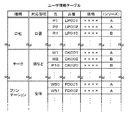
図14は、化粧品データベース114の一例の構成を示す。種類は、例えば化粧品を用途に応じて大まかに分類したもので、それぞれ顔内の部位と対応付けられる。対応部位は、図14では具体名となっているが、実際的には、計測ポイントで示す方が好ましいと考えられ、例えば、図11Aを用いて説明した計測ポイントの識別情報PoIDを用いることができる。各種類または対応部位毎に色別、品番別にデータが登録され、それぞれ価格情報が対応付けられる。この図14の例では、色情報が化粧品メーカによる命名法に基づき格納されている。この場合、別途、化粧品メーカの命名法に基づく色名と、色度図上の座標とを対応付けるテーブルを用意すると、好ましい。シリーズは、例えば化粧品メーカによる商品の分類である。
FIG. 14 shows an exemplary configuration of the
化粧品情報の検索方法の一例として、2次解析結果に基づき、自己メイクによる口唇(図10の例では、口唇155)の色が理想メイクによる色に比べて濃すぎると判定されたとする。なお、「色がある色に対して濃い」という場合、実際には、例えば色度図上の方向を示す必要がある。ここでは、繁雑さを避けるため、単に「濃い、薄い」と表現する。
As an example of a cosmetic information search method, it is assumed that the color of the lip by self-makeup (
このような場合、例えば、化粧品データベース114を参照して、部位が対応する化粧品(この場合は口紅)の中から、参照情報における口唇155の色に対応するの化粧品を抽出し、この化粧品の情報をパッケージデータ140に含ませてユーザに提供することが考えられる。このとき、この化粧品の購入方法を示す情報も、化粧品情報と共にユーザに提供すると、より好ましい。例えば、この化粧品をインターネット130を介して購入可能なウェブサイトのURLを、化粧品情報と共にユーザに提供する。ユーザは、2次解析結果を受け取ったその場で化粧品の注文を行うことができる。
In such a case, for example, referring to the
なお、上述では、図6のフローチャートにおけるステップS26で自己メイクによる特徴情報と理想メイクによる特徴情報との差が所定以上の場合に、化粧品の紹介を行うように説明したが、これはこの例に限定されない。すなわち、ステップS26においてこれらの差が所定未満であるとされた場合にも、化粧品の紹介を行うようにできる。この場合は、例えば、ユーザ情報データベース113内のユーザ情報テーブルにおける使用化粧品情報に基づき、ユーザが使用している化粧品と同等以上の効果を持つ他の化粧品や、同等の効果を持ちより低価格の化粧品を紹介することが考えられる。
In the above description, the cosmetic product is introduced when the difference between the feature information based on self-makeup and the feature information based on ideal makeup is greater than or equal to a predetermined value in step S26 in the flowchart of FIG. It is not limited. That is, even when it is determined in step S26 that these differences are less than a predetermined value, cosmetics can be introduced. In this case, for example, based on the used cosmetic information in the user information table in the
2−2−4.補足
なお、化粧では、微妙な色合いを用いることが多いため、1次解析や2次解析において正確な解析を行うためには、理想メイクによる顔を撮影した画像データと、自己メイクによる顔を撮影した画像データとで、色の見え方が等しくなるようにする必要がある。それと共に、画像データを計測して得られた色情報と、例えば化粧品データベース114に登録される各化粧品の色情報とを共通の表示系で比較可能とする必要がある。
2-2-4. Supplement Since makeup often uses subtle shades, in order to perform an accurate analysis in the primary and secondary analysis, the image data obtained by photographing the face with ideal makeup and the face by self-makeup are photographed. It is necessary to make the color appearance the same with the processed image data. At the same time, it is necessary to be able to compare the color information obtained by measuring the image data and the color information of each cosmetic registered in the
一例として、既に説明したように、理想メイクによる顔の撮影時および自己メイクによる顔の撮影時に、色、濃淡、明るさなどの基準となる被写体を、ユーザの顔と同一の画像データ中に含まれるように撮影を行う。この基準となる被写体は、例えば、ホワイトバランスに基づく補正を行うための白色の部分と、各色毎に色補正を行うための色見本部分とで構成する。この基準となる被写体を、画面内の所定位置に配置して、撮影を行う。 As an example, as described above, when photographing a face with ideal makeup and photographing a face with self-makeup, the reference object such as color, lightness and brightness is included in the same image data as the user's face Take a photo as shown. The reference subject includes, for example, a white portion for performing correction based on white balance and a color sample portion for performing color correction for each color. The reference subject is placed at a predetermined position in the screen and photographing is performed.
画像データに基づき1次解析を行う際や、カメラ装置101Aおよび101Bで撮影され得られた画像データがセンサ情報データベース112に格納される際などに、先ず、画像データによる画面内の所定位置に配置される、上述した基準となる被写体を所定に計測し、計測結果に基づき、白色部分の色情報と色見本部分の色情報とを取得する。そして、これらの色情報と、基準となる被写体の標準光源下における色情報とに基づき、カメラ装置101Aおよび101Bから得られた画像データを正規化することが考えられる。
When performing a primary analysis based on image data, or when image data obtained by the
また、顔の立体形状における凹凸と、撮影時の光源の方向により、画像データ中の顔の所定部分に影部が生じることがあり、この影部は、色の計測に影響する。この影響は、例えば、参照情報として登録される顔の立体画像に対して光源のシミュレートを行い、影部の発生を予測することで、回避可能であると考えられる。例えば、自己メイクによる画像データに対して、鼻周辺など影部の発生が予測される部分について計測を行って影らしき部分を抽出し、この抽出された影部分情報に基づき光源シミュレートを行い、光源の方向を予測する。この予測された光源方向に基づき、他の影部の発生を予測する。 In addition, a shadow portion may occur in a predetermined portion of the face in the image data depending on the unevenness in the three-dimensional shape of the face and the direction of the light source at the time of shooting, and this shadow portion affects the color measurement. This effect can be avoided by, for example, simulating a light source on a stereoscopic face image registered as reference information and predicting the occurrence of shadows. For example, for the image data by self-make, measure the part where shadows are predicted to occur such as around the nose, extract the part that appears to be shadowed, perform light source simulation based on this extracted shadow part information, Predict the direction of the light source. Based on the predicted light source direction, the occurrence of another shadow portion is predicted.
このように、この実施の第1の形態の第1の応用例によれば、ユーザは、自宅にいながらにして理想メイクにより近いメイクアップを簡単に行うことができ、また、必要な化粧品の情報の入手や購入も、その場で行うことができる。 As described above, according to the first application example of the first embodiment, the user can easily perform makeup that is closer to the ideal makeup while at home, and obtain necessary cosmetic information. And purchases can also be made on the spot.
2−3.実施の第1の形態の第2の応用例について
次に、この発明の実施の第1の形態の第2の応用例について説明する。第2の応用例は、実施の第1の形態を、スポーツなどの身体フォームに対するアドバイスを行うスポーツ向けのラーニングシステムに適用する例である。
2-3. Second Application Example of the First Embodiment Next, a second application example of the first embodiment of the present invention will be described. The second application example is an example in which the first embodiment is applied to a sports learning system that provides advice on body forms such as sports.
2−3−1.システムの概要
この第2の応用例によるスポーツ向けラーニングシステムについて概略的に説明する。図15は、このスポーツ向けラーニングシステムの概要を説明するための一例の流れを示すフローチャートである。先ず、ユーザにとって理想的なフォームの撮影がなされる(ステップS30)。例えば、トレーナやインストラクタ(以下、指導員)によりユーザに対して正しいフォームで動作するように指示がなされ、ユーザがこの指示に従い動作する様子を、動画として撮影する。ここで撮影されたフォームを、理想フォームと呼ぶ。理想フォーム撮影の際のユーザの動作は、実際のフォームに基づく動作に対して遅い動きであってもよいものとする。
2-3-1. System Overview A sports learning system according to the second application example will be schematically described. FIG. 15 is a flowchart showing an exemplary flow for explaining the outline of this sports learning system. First, a form ideal for the user is photographed (step S30). For example, a trainer or an instructor (hereinafter referred to as an instructor) gives an instruction to the user to operate in the correct form, and a picture of the user operating according to the instruction is taken as a moving image. The form photographed here is called an ideal form. It is assumed that the user's operation at the time of ideal form shooting may be slower than the operation based on the actual form.
理想フォームが撮影されたビデオデータは、サーバシステムに送信される(ステップS31)。サーバシステム側では、送信されたこのビデオデータに基づきフォームの特徴を示す特徴情報を抽出し、抽出されたフォームの特徴情報を、ユーザの参照情報としてユーザ情報データベースに登録する(ステップS32)。 The video data in which the ideal form is photographed is transmitted to the server system (step S31). On the server system side, feature information indicating the feature of the form is extracted based on the transmitted video data, and the extracted feature information of the form is registered in the user information database as user reference information (step S32).
一方、ユーザは、後に、トレーニング施設や自宅などでフォームの再現動作を行い、その様子を動画として撮影する(ステップS33)。ここで撮影されたフォームを、自己フォームと呼ぶ。そして、自己フォームを撮影したビデオデータをサーバシステムに送信する(ステップS34)。サーバシステム側では、ユーザから送信されたビデオデータを解析して、フォームの特徴を示す特徴情報を抽出し、抽出されたこの特徴情報と、当該ユーザの参照情報として登録されている特徴情報とを比較する(ステップS35)。比較の結果、両者の差が所定以上であるとされれば(ステップS36)、ユーザのフォームに何らかの問題があると考えることができる。そこで、サーバシステム側では、ユーザから送信されたビデオデータおよび/または当該ビデオデータを解析した解析結果に対して、問題部分を抽出可能なように2次解析処理を施す(ステップS37)。 On the other hand, the user later performs a form reproduction operation at a training facility or at home, and shoots the state as a moving image (step S33). The form photographed here is called a self-form. And the video data which image | photographed the self-form is transmitted to a server system (step S34). On the server system side, the video data transmitted from the user is analyzed, the feature information indicating the feature of the form is extracted, and the extracted feature information and the feature information registered as the reference information of the user are included. Compare (step S35). As a result of the comparison, if the difference between the two is greater than or equal to a predetermined value (step S36), it can be considered that there is some problem in the user's form. Therefore, the server system performs secondary analysis processing on the video data transmitted from the user and / or the analysis result obtained by analyzing the video data so that the problem part can be extracted (step S37).
サーバシステム側は、2次解析処理の結果に基づき、ユーザに対してフォームのアドバイスを行うアドバイス情報を作成する。作成されたアドバイス情報は、当該ユーザに対して送信される(ステップS38)。このとき、アドバイス情報に対応して、お勧めのスポーツウェアやスポーツ用品を示す情報を当該アドバイス情報に付加して送信することができる。ユーザは、自己トレーニングや自己レッスンにより自己のフォームを理想フォームに近付けることができると共に、必要などの情報を得ることができる。 The server system side creates advice information for giving advice of the form to the user based on the result of the secondary analysis processing. The created advice information is transmitted to the user (step S38). At this time, corresponding to the advice information, information indicating recommended sportswear and sports equipment can be added to the advice information and transmitted. The user can bring his / her own form closer to the ideal form through self-training and self-learning, and obtain necessary information.
なお、ステップS36で、差が所定未満であるとされた場合には、サーバシステム側からユーザに対して、現在のフォームで問題が無い旨を示す通知が送信される(ステップS39)。このとき、ユーザ情報データベースに登録された当該ユーザの情報などに基づき、関連商品の購入情報などを、当該通知に付加して送信することが考えられる。 If it is determined in step S36 that the difference is less than the predetermined value, a notification indicating that there is no problem in the current form is transmitted from the server system side to the user (step S39). At this time, based on the information of the user registered in the user information database and the like, it is conceivable that purchase information of related products is added to the notification and transmitted.
2−3−2.第2の応用例に適用可能なシステムについて
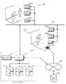
図16は、この実施の第1の形態の第2の応用例に適用可能な一例のシステムを概略的に示す。なお、以下では、この第2の応用例を、実施の第1の形態をゴルフのスウィングのフォームをユーザに対してアドバイスする、ゴルフ教習システムに適用したものとして説明する。
2-3-2. System applicable to second application example FIG. 16 schematically shows an example system applicable to the second application example of the first embodiment. In the following description, the second application example will be described assuming that the first embodiment is applied to a golf learning system that advises a user of a golf swing form.
図16に例示する第2の応用例に適用可能なシステムは、基本的には、図1を用いて上述した実施の第1の形態に適用可能なシステムや、図7を用いて上述した実施の第1の形態の第1の応用例に適用可能なシステムと同様の構成を有する。なお、図16において、上述した図7と共通する部分には同一の符号を付し、詳細な説明を省略する。 The system applicable to the second application example illustrated in FIG. 16 is basically the system applicable to the first embodiment described above with reference to FIG. 1 and the implementation described above with reference to FIG. It has the same configuration as the system applicable to the first application example of the first form. In FIG. 16, the same reference numerals are given to the same parts as those in FIG. 7 described above, and detailed description thereof is omitted.
施設160は、例えば指導員がユーザに対してフォームの指導などを行うようにされた場所である。この図16の例では、2台のビデオカメラ装置161Aおよび162A、ならびに、リーダ163Aが施設160に配置され、それぞれオープンまたはこのシステムでクローズされたネットワーク103に接続される。2台のビデオカメラ装置161Aおよび162Aのうち一方(ビデオカメラ装置161Aとする)は、ユーザのスウィングの様子を全体的に撮影するためのもので、他方(ビデオカメラ装置162A)は、ゴルフクラブのヘッドにおけるインパクトの様子を撮影するためのものである。リーダ163Aは、図示されないユーザ媒体15から例えばユーザIDを読み取る。
The
一方、ユーザの自宅164や図示されないゴルフ練習場のレーンといった、ユーザが自分自身でフォームのトレーニングを行うような場所に、2台のビデオカメラ装置161Bおよび162B、ならびに、リーダ163Bが配置され、それぞれネットワーク103に接続される。この場合も、施設160と同様に、2台のビデオカメラ装置161Bおよび162Bは、それぞれスウィング全体およびインパクトの様子を撮影するためのものである。
On the other hand, two
ビデオカメラ装置161A、162A、161Bおよび162Bは、それぞれ被写体を撮影し、得られたビデオデータを所定に圧縮符号化して出力すると共に、ビデオデータを撮影した時刻を示す時刻情報と、ビデオカメラ装置161A、162A、161Bおよび162Bそれぞれを識別するセンサIDとを、当該ビデオデータに対応付けて出力する。時刻情報は、ビデオカメラ装置161A、162A、161Bおよび162Bのそれぞれにおいて発生され、フレーム単位で時刻指定が可能とされたタイムコードを用いることができる。
Each of the
なお、ビデオカメラ装置161A、162A、161Bおよび162Bは、高速な動きを撮影する必要があるので、通常のビデオカメラと比べてフレームレートがより高速なものであると好ましい。さらに、ビデオカメラ装置161A、162A、162Aおよび162Bは、フラッシュライトシステムと連動したものであると、より好ましい。システムの構成などによっては、インパクトの様子を撮影するビデオカメラ装置162Aおよび162Bは、省略可能である。
Note that the
リーダ163Aおよび163Bは、図示されないユーザ媒体15に記憶されたユーザIDを読み出す。ユーザ媒体15は、既に述べたように様々な種類のものを適用可能であるが、この第2の応用例では、ユーザ媒体15は、上述した、合成樹脂製のカード内に不揮発性メモリ、送受信部および発電部を有するカード型記憶媒体であるものとする。ユーザ媒体15は、予めユーザIDが記憶され対応するユーザに渡されているものとする。
The
上述の第1の応用例と同様に、ビデオカメラ装置161Aおよび162Aから出力されるビデオデータと、リーダ163Aで読み出されたユーザIDとが所定に対応付けられて、ネットワーク103に対して送信されるものとする。これは、ビデオカメラ装置161Bおよび162B、ならびに、リーダ163Bについても同様とする。また、この第2の応用例においても上述の第1の応用例と同様に、ユーザIDは、ユーザ媒体15からリーダ163Aにより読み出されるのに限らない。例えば、リーダ163Aをキーボードなど所定の入力手段を設けた入力装置とし、ユーザがマニュアルでユーザIDを入力するようにしてもよい。
Similar to the first application example described above, the video data output from the
なお、図16では、ネットワーク103に対して接続されるビデオカメラ装置およびリーダが配置される施設などが、施設160およびユーザの自宅164のみとなっているが、実際には、さらに多数の施設等に設けられた ビデオカメラ装置やリーダが、ネットワーク103に対して識別可能に接続される。
In FIG. 16, the facility where the video camera device and the reader connected to the
サーバシステム104’は、図7を用いて説明したサーバシステム104に対応するもので、例えばサーバ部110’、解析システム部111’、センサ情報データベース112’、ユーザ情報データベース113’およびゴルフ情報データベース166を有する。ゴルフ情報データベース166は、ゴルフ用品の情報や、ゴルフ練習場の情報など、ゴルフに関する情報が登録される。サーバ部110’は、このシステムの全体の制御や管理を行い、ビデオカメラ装置161A、162A、161Bおよび162Bから送信されたビデオデータ、ユーザIDおよび時刻情報を、センサ情報データベース112’に所定に格納する。
The
解析システム部111’は、ビデオカメラ装置161A、162A、161Bおよび162Bで取得されセンサ情報データベース112’に格納されたビデオデータに対して、一例を後述するような1次解析処理を行う。さらに、1次解析の解析結果に基づき閾値判断を行い、判断結果に応じて一例を後述するような2次解析を行う。
The
サーバシステム104’は、サーバ部110’によりインターネット130に接続される。インターネット130には、例えばユーザが自宅164などで利用可能な、パーソナルコンピュータなどによるユーザ端末165が接続される。なお、図16の例では、インターネット130に接続されるユーザ端末がユーザ端末165のみとなっているが、実際には、さらに多数のユーザ端末の接続が可能である。また、インターネット130には、インターネット130に向けてウェブページ公開などウェブサービスを提供するサーバであるウェブサーバ132が接続される。
The server system 104 'is connected to the
なお、上述では、ユーザの自宅164に配置されるビデオカメラ装置161Bおよび162Bがネットワーク103に接続されているように説明したが、これはこの例に限定されない。例えば、ビデオカメラ装置161Bおよび162Bがパーソナルコンピュータであるユーザ端末165に接続されるものとし、ビデオカメラ装置161Bおよび162Bによる撮影の制御をユーザ端末165にて行い、ビデオカメラ装置161Bおよび162Bから出力されたビデオデータをユーザ端末165からインターネット130を介してサーバシステム104’に送信するようにしてもよい。
In the above description, the
センサ情報データベース112’およびユーザ情報データベース113’の構成について、概略的に説明する。センサ情報データベース112’の構成は、図2を用いて説明したセンサ情報データベース112と同様とされ、ビデオデータを識別するデータIDに対し、当該ビデオデータの格納場所を示すポインタ情報と、ユーザIDと、時刻情報とが対応付けられて、センサ情報テーブルに登録される。この場合、時刻情報は、例えば当該ビデオデータの撮影が開始された時刻とされる。
The configurations of the sensor information database 112 'and the user information database 113' will be schematically described. The configuration of the
ユーザ情報データベース113’は、ユーザ情報が登録されるユーザ情報テーブルと、参照情報テーブルとを有する。図17は、ユーザ情報データベース113’内のユーザ情報テーブルの一例の構成を示す。ユーザ情報テーブルは、ユーザを識別するユーザID毎に、ユーザIDが対応するユーザの属性情報と、当該ユーザのゴルフに関する情報とが登録される。ユーザの属性情報は、例えば、そのユーザの名前、連絡先(電子メールアドレス)といったユーザを識別する情報と、年齢、身長、体重といったユーザの身体的特徴を示す情報とからなる。ゴルフ関連情報は、そのユーザのゴルフに関連する情報であって、例えば、ハンデ、ドライバでの飛距離といったユーザのゴルフの技術に関する情報や、ユーザが使用しているゴルフクラブなど、ゴルフ用品に関する情報からなる。これらの情報は、例えば、ユーザがこのシステムの利用を開始する際に設定される。参照情報テーブルの構成については、後述する。 The user information database 113 'includes a user information table in which user information is registered and a reference information table. FIG. 17 shows an example of the configuration of the user information table in the user information database 113 '. In the user information table, for each user ID for identifying a user, user attribute information corresponding to the user ID and information regarding the user's golf are registered. The user attribute information includes, for example, information for identifying the user such as the user's name and contact information (e-mail address), and information indicating the physical characteristics of the user such as age, height, and weight. The golf-related information is information related to the user's golf, for example, information related to the user's golf technology such as a handicap and a driver's flight distance, and information related to golf equipment such as a golf club used by the user. Consists of. These pieces of information are set when the user starts using the system, for example. The configuration of the reference information table will be described later.
このような構成のシステムにおいて、図15を用いて説明した流れに従い、先ずユーザは、施設160で指導員の指導の下、理想フォームによるスウィング動作を行い、例えばビデオカメラ装置161Aを用いてそのフォームを撮影する(ステップS30)。また、ユーザは、リーダ163Aにユーザ媒体15に記憶されるユーザIDを読み取らせる。フォームが撮影されたビデオデータは、撮影された時刻を示す時刻情報と、ビデオカメラ装置161Aを識別するセンサIDと、ユーザIDとが付加されて、ネットワーク103を介してサーバシステム104’に送信される(ステップS31)。
In the system configured as described above, according to the flow described with reference to FIG. 15, the user first performs a swing operation using an ideal form under the guidance of an instructor at the
サーバシステム104’は、これらビデオデータと、当該ビデオデータに付加された時刻情報、センサID、ユーザIDとをサーバ部110’に供給する。ビデオデータは、例えばサーバ部110’が有するストレージ装置に所定に格納される。サーバ部110’は、センサ情報データベース112’のセンサIDが対応するセンサ情報テーブルに対し、ビデオデータの格納場所を示すポインタ情報、時刻情報およびユーザIDを所定に対応付けて格納する。
The
ビデオデータは、ポインタ情報やユーザIDなどに基づきサーバ部110’に読み出され、解析システム部111’に供給される。解析システム部111’は、供給されたビデオデータに対して所定の処理を施し、当該ビデオデータに対する参照情報を生成する。参照情報は、参照情報を識別するための参照情報IDを付加され、関連する他の情報と対応付けられて、ユーザ情報データベース113’内の参照情報テーブルに所定に登録される(ステップS32)。
The video data is read to the server unit 110 'based on the pointer information, the user ID, etc., and supplied to the analysis system unit 111'. The
ユーザは、後に、例えばユーザの自宅164で、自分自身でスウィング動作を行い、ビデオカメラ装置161Bを用いてフォームを撮影する(ステップS33)。また、ユーザは、リーダ163Bにユーザ媒体15に記憶されるユーザIDを読み出させる。自己フォームが撮影されたビデオデータは、撮影された時刻を示す時刻情報と、ビデオカメラ装置161Bを識別するセンサIDと、ユーザIDとが付加されて、ネットワーク103を介してサーバシステム104’に送信される(ステップS34)。
The user later performs a swing operation by himself / herself, for example, at the user's
サーバシステム104’は、これら自己フォームによるビデオデータと、当該ビデオデータに付加された時刻情報、センサIDおよびユーザIDとをサーバ部110’に供給する。ビデオデータは、例えばサーバ部110’が有するストレージ装置に所定に格納される。ビデオデータは、ポインタ情報やユーザIDなどに基づきサーバ部110’に読み出され、解析システム部111’に供給される。解析システム部111’は、供給されたビデオデータに対して所定の処理を施す。そして、サーバ部110’は、供給されたユーザIDに基づきユーザ情報データベース113’内の参照情報テーブルから対応する参照情報を抽出し、参照情報と、自己フォームによるビデオデータに基づく処理結果とを比較し、1次解析を行う(ステップS35)。
The server system 104 'supplies the video data in the self-form and the time information, sensor ID, and user ID added to the video data to the server unit 110'. For example, the video data is stored in a predetermined storage device in the
1次解析による比較の結果、参照情報と自己フォームによるビデオデータに基づく処理結果の差分が所定以上あれば(ステップS36)、サーバ部110’は、自己フォームによるビデオデータ、或いは、自己フォームによるビデオデータに基づく処理結果に対して、2次解析処理を行う(ステップS37)。そして、2次解析結果に基づきアドバイス情報を生成し、例えば電子メールなどを用いてユーザに対して送信する。 As a result of the comparison by the primary analysis, if the difference between the reference information and the processing result based on the video data based on the self-form is greater than or equal to a predetermined value (step S36), the server unit 110 ' A secondary analysis process is performed on the processing result based on the data (step S37). Then, advice information is generated based on the secondary analysis result, and transmitted to the user using e-mail, for example.
ユーザは、サーバ部110’から送信された、アドバイス情報が添付された電子メールを、例えばユーザの自宅164においてユーザ端末165を用いて受信することで、アドバイス情報に基づきより理想フォームに近いフォームのスウィングを学習することが可能となる。
The user receives the e-mail attached with the advice information transmitted from the
ここで、アドバイス情報と共に、当該ユーザの参照情報に対応するビデオデータをユーザに対して送信することが考えられる。すなわち、アドバイス情報と当該ビデオデータとを一纏めにパッケージングし、このパッケージデータを電子メールに添付して送信する。パッケージデータの構成は、図9を用いて説明したのと同様であるので、ここでの説明は省略する。ユーザは、この電子メールをユーザ端末165で受信して、ビデオデータを再生させながらアドバイス情報を参照することで、より効果的にスウィングの学習を行うことができる。
Here, it is conceivable to transmit video data corresponding to the reference information of the user together with the advice information to the user. That is, the advice information and the video data are packaged together, and the package data is attached to an electronic mail and transmitted. Since the configuration of the package data is the same as that described with reference to FIG. 9, the description thereof is omitted here. The user can learn the swing more effectively by receiving the e-mail at the
なお、ビデオデータは、ストリーム配信の形態でアドバイス情報とパッケージングすることが好ましい。一例として、サーバ部110’においてビデオデータに対して所定にURLを与え、当該URLへのアクセスに対してストリーミング配信可能なように送信制御を行う。ユーザ側では、ビデオデータの全長分の受信を待たずに、当該ビデオデータを再生することができる。また、理想フォームおよび/または自己フォームの時系列方向での分解画像をアドバイス情報と共にパッケージングすることも考えられる。例えば、サーバ部110’は、理想フォームおよび/または自己フォームによるビデオデータのフレーム画像を、所定時間間隔毎に抽出し、アドバイス情報などと共にパッケージングする。
Note that video data is preferably packaged with advice information in the form of stream distribution. As an example, a predetermined URL is given to video data in the
さらに、この第2の応用例においても、アドバイス情報などを電子メールに添付して送信するのに限られない。すなわち、上述した第1の応用例と同様に、アドバイス情報、理想フォームおよび/または自己フォームによよるビデオデータや当該ビデオデータの時系列方向での分解画像を、ウェブサイト上のウェブページとして、インターネット130上で閲覧可能としてユーザに提示することが考えられる。所定のタイミングの分解画像に対して対応するアドバイス情報を関連付けて表示することも考えられる。
Further, in the second application example, advice information or the like is not limited to being attached to an electronic mail and transmitted. That is, as in the first application example described above, the advice data, the ideal form and / or the self-form video data and the decomposed image in the time series direction of the video data as a web page on the website, It is conceivable to present it to the user as being viewable on the
2−3−3.第2の応用例による解析処理の例について
次に、この実施の第1の形態の第2の応用例に適用可能な1次解析処理および2次解析処理の例について説明する。先ず、1次解析処理の例について説明する。1次解析処理は、例えば、ユーザの身体における複数の所定ポイントを計測ポイントとして設定し、理想フォームおよび自己フォームのそれぞれについて各々の計測ポイントの位置を測定し、理想フォームについて計測された値と、自己フォームについて計測された値とを比較して差分を計算する。そして、この差分を、所定の閾値と比較することが考えられる。
2-3-3. Example of Analysis Processing According to Second Application Example Next, examples of primary analysis processing and secondary analysis processing applicable to the second application example of the first embodiment will be described. First, an example of the primary analysis process will be described. In the primary analysis process, for example, a plurality of predetermined points on the user's body are set as measurement points, the positions of the measurement points are measured for each of the ideal form and the self-form, and the values measured for the ideal form, Compare the measured value for the self-form and calculate the difference. It is conceivable to compare this difference with a predetermined threshold.
図18を用いて、計測ポイントの例について説明する。なお、図18は、理想フォームによるスウィング開始時の様子を捉えたフレーム画像であるものとする。身体の動きを解析する場合、身体の主要な関節を計測ポイントとして観測することが考えられる。図18の例では、ユーザの身体400における左右それぞれについて、肩部401Aおよび401B、肘部401Cおよび401D、手首部401Eおよび401F、股関節部401Gおよび401H、膝部401Iおよび401J、ならびに、足首部401Kおよび401Lを計測ポイントとし、さらに、頭頂部402を計測ポイントに加えている。なお、これらの計測ポイントは一例であって、この例に限定されるものではない。
An example of measurement points will be described with reference to FIG. Note that FIG. 18 is a frame image that captures the state at the start of swing by the ideal form. When analyzing body movements, it is conceivable to observe major joints of the body as measurement points. In the example of FIG. 18, shoulders 401A and 401B,
なお、図18において太線で例示されるように、身体400は、各計測ポイント401A〜401L、402を所定に結んだ直線と、胴体の中心線403とで表現することができると考えられる。このように、身体400の構造を簡略化して表現することで、後述する1次解析処理や2次解析処理が容易になることが期待される。
In addition, as illustrated by a thick line in FIG. 18, the
理想フォームや自己フォームによるスウィングの様子を撮影したビデオデータから所定のフレームを複数枚、抽出し、抽出された複数枚のフレーム画像のそれぞれについて、これら計測ポイント401A〜401Lおよび計測ポイント402の位置を測定する。例えば、スウィングの様子を撮影したビデオデータの各フレームを解析し、スウィングの開始点、クラブのヘッドにボールが当たる瞬間、ならびに、スウィングの終了点が撮影されたフレームを抽出する。これらのフレームに基づきさらに時系列的な経過点のフレームを抽出することも考えられる。 A plurality of predetermined frames are extracted from the video data obtained by photographing the swing state of the ideal form and the self-form, and the positions of the measurement points 401A to 401L and the measurement points 402 are determined for each of the extracted frame images. taking measurement. For example, each frame of video data obtained by shooting a swing state is analyzed, and a frame where a swing start point, a moment when a ball hits a club head, and a swing end point are extracted is extracted. It is also conceivable to extract a frame at a time-series elapsed point based on these frames.
ここで、各フレーム画像から、各計測ポイント401A〜401L、402を抽出する必要がある。一例として、予め解析システム部111’にパターン情報が登録されているマークを、フォームの撮影時にユーザの身体400の各計測ポイント401A〜401L、402に取り付ける方法が考えられる。マークは、外見上の特徴抽出が容易でユーザの動きに対する影響が少ないものであれば、特に限定されない。例えば、所定の形状を有したり、所定のパターンが表示された物体や、LED(Light Emitting Diode)などによる発光体をマークとして用いることが考えられる。解析システム部111’は、解析時に、フレーム画像からこのマークを検出し、各計測ポイント401A〜401L、402を特定する。
Here, it is necessary to extract the measurement points 401A to 401L and 402 from each frame image. As an example, a method is conceivable in which a mark whose pattern information is registered in advance in the
これに限らず、フレーム画像から直接的に各計測ポイント401A〜401L、402を抽出してもよい。例えば、各フレーム画像を時系列的に解析し、関節部分など抽出することが考えられる。 However, the measurement points 401A to 401L and 402 may be directly extracted from the frame image. For example, it is conceivable to analyze each frame image in time series and extract a joint portion and the like.
このようにして、理想フォームによるビデオデータから求められた各計測ポイントの位置情報は、参照情報として参照情報テーブルに登録される。図19は、ユーザ情報データベース113’内の参照テーブルの構成例を示す。ここでは、図19Aおよび図19Bに例示されるように、参照情報テーブルを複数のテーブルから構成している。参照情報テーブルの構成はこれに限らず、複数のテーブルを1つに纏めてもよいし、さらに分割することも考えられる。なお、参照情報テーブルにおいて、各計測ポイント401A〜401L、402は、それぞれ固有の識別情報PoIDにより表される。 Thus, the position information of each measurement point obtained from the video data in the ideal form is registered in the reference information table as reference information. FIG. 19 shows a configuration example of a reference table in the user information database 113 '. Here, as illustrated in FIGS. 19A and 19B, the reference information table is composed of a plurality of tables. The configuration of the reference information table is not limited to this, and a plurality of tables may be combined into one, or further divided. In the reference information table, each of the measurement points 401A to 401L and 402 is represented by unique identification information PoID.
図19Aは、1の参照情報が登録される一例のテーブルである。参照情報自体は、参照情報IDを用いて他の参照情報と識別される。参照情報は、例えば1のビデオデータから抽出された複数フレームの情報からなり、複数フレームのそれぞれについて、各計測ポイント401A〜401L、402の位置を示す位置情報が登録される。フレームのそれぞれは、例えばタイムコードを用いてフレーム単位で表される。テーブルには、上述した、スウィングの開始点が撮影されたフレーム、クラブのヘッドにボールが当たる瞬間が撮影されたフレーム、ならびに、スウィングの終了点が撮影されたフレームの3フレームのみを登録することが考えられる。 FIG. 19A is an example table in which one piece of reference information is registered. The reference information itself is identified from other reference information using the reference information ID. The reference information includes, for example, information on a plurality of frames extracted from one video data, and position information indicating the positions of the measurement points 401A to 401L and 402 is registered for each of the plurality of frames. Each of the frames is expressed in units of frames using, for example, a time code. In the table, register only the above-mentioned three frames: the frame where the swing start point was shot, the frame where the ball hits the club head, and the frame where the swing end point was shot. Can be considered.
これに限らず、理想フォームを撮影したビデオデータのフレームを全て登録してもよい。全てのフレームを登録する場合には、上述の3フレームが識別可能なようにされる。また、全てのフレームを登録する場合、上述の3フレームのみについてのみ計測ポイントを抽出し、他のフレームについては計測ポイントの抽出を省略することも考えられる。 However, the present invention is not limited to this, and all frames of video data obtained by photographing an ideal form may be registered. When all the frames are registered, the above-described three frames are made identifiable. In addition, when all the frames are registered, it is also conceivable that measurement points are extracted only for the three frames described above, and measurement point extraction is omitted for the other frames.
図19Bは、参照情報のそれぞれについて、属性情報が格納される属性情報テーブルの一例の構成を示す。例えば、参照情報毎に、対応するユーザID、取得された日付、参照情報に対応するビデオデータの識別情報が対応付けられると共に、所定の属性情報が対応付けられる。所定の属性情報は、例えば、任意の説明、施設160の名称や、施設160におけるユーザの担当者などを登録することが考えられる。
FIG. 19B shows an exemplary configuration of an attribute information table in which attribute information is stored for each piece of reference information. For example, for each reference information, a corresponding user ID, an acquired date, identification information of video data corresponding to the reference information are associated with predetermined attribute information. As the predetermined attribute information, for example, an arbitrary description, the name of the
1次解析は、一例として次のようにして行うことが考えられる。先ず、自己フォームを撮影したビデオデータの所定フレーム(例えばスウィング開始時のフレームとする)について、各計測ポイント401A〜401L、402の位置を求める。これら自己フォームによるビデオデータの所定フレームにおける各計測ポイント401A〜401L、402の位置を示す位置情報と、参照情報テーブルに登録された対応するフレームから抽出された各計測ポイント401A〜401L、402の位置を示す位置情報とに対し、計測ポイント毎に、計測ポイントに応じた重み付けをそれぞれ所定に行い、重み付けされた位置情報に関し、対応する計測ポイントの組それぞれについて位置情報の差分の絶対値を計算する。差分は、例えばベクトルの大きさとして求めることが考えられる。そして、計測ポイントの組それぞれについて計算された差分の絶対値を加算し、加算結果を所定の閾値と比較する。比較の結果、加算結果が閾値より大きいと判断されれば(図13のステップS36)、2次解析を行う。
The primary analysis may be performed as follows as an example. First, the positions of the measurement points 401A to 401L and 402 are obtained for a predetermined frame (for example, a frame at the start of swing) of video data obtained by photographing the self-form. Position information indicating the positions of the
2次解析は、一例として次のようにして行うことが考えられる。1次解析の際に用いた、参照情報に基づく各計測ポイント401A〜401L、402の位置を示す位置情報と、自己フォームに基づく各計測ポイント401A〜401L、402の位置を示す位置情報とに関し、位置が対応する計測ポイントの組について位置情報の差分をベクトル情報として求める。そして、各計測ポイント401A〜401L、402それぞれの差分情報を総合的に解析する。解析内容としては、身体400の捻れや、腕の振り、重心の移動などが考えられる。
The secondary analysis may be performed as follows as an example. Regarding the position information indicating the positions of the measurement points 401A to 401L and 402 based on the reference information and the position information indicating the positions of the measurement points 401A to 401L and 402 based on the self-form used in the primary analysis, A difference in position information is obtained as vector information for a set of measurement points corresponding to positions. And the difference information of each
なお、例えば上述のように、スウィングの開始点が撮影されたフレーム、クラブのヘッドにボールが当たる瞬間が撮影されたフレーム、ならびに、スウィングの終了点が撮影されたフレームといった複数フレームが解析対象となっている場合、1次解析の結果に基づく判断は、解析対象のフレーム毎に行ってもよいし、解析対象の複数フレーム全ての解析結果を用いて行ってもよい。フレーム毎に1次解析の結果に基づく判断を行った場合には、2次解析も、対応するフレーム毎に行うことが考えられる。 For example, as described above, a plurality of frames such as a frame in which the swing start point is shot, a frame in which the ball hits the club head, and a frame in which the swing end point is shot are analyzed. In such a case, the determination based on the result of the primary analysis may be performed for each analysis target frame, or may be performed using the analysis results of all the analysis target frames. When the determination based on the result of the primary analysis is performed for each frame, the secondary analysis may be performed for each corresponding frame.
2次解析結果に基づき、ユーザに対してスウィングに関するアドバイスを行うアドバイス情報を生成し、ユーザに提示するとよい。サーバシステム104’において、例えば予測される2次解析の結果に応じたアドバイス用のテキストデータを予め用意する。そして、実際の2次解析の結果に基づきアドバイス用のテキストデータを所定に選択したり、必要に応じてアドバイス用のテキストデータを複数、組み合わせて1のテキストデータとし、これを、ユーザに対するスウィングのアドバイス情報として提示する。アドバイス情報は、例えばパッケージデータ140に含めてユーザに提供される。
Based on the secondary analysis result, it is preferable to generate advice information for giving advice on swing to the user and present it to the user. In the
この実施の第1の形態の第2の応用例でも、上述した第1の応用例と同様に、2次解析の結果に応じてユーザに対して商品を紹介することができるようにされている。第2の応用例がゴルフ教習システムに適用されたこの例では、2次解析結果に応じてゴルフ用品の紹介を行うことが考えられる。例えば、2次解析結果に基づきゴルフ情報データベース166を参照し、適当と思われるゴルフ用品を選択する。一例として、ゴルフ情報データベース166に対し、ゴルフクラブにの情報を、長さ、重さなどのゴルフクラブの特性を示す情報と対応付けて登録しておき、2次解析の結果に基づき、ユーザのフォームをより理想フォームに近付けるのに適当なゴルフクラブを検索し、検索の結果得られた商品の情報をユーザに提示する。
Also in the second application example of the first embodiment, as in the first application example described above, the product can be introduced to the user according to the result of the secondary analysis. . In this example in which the second application example is applied to the golf learning system, it is conceivable to introduce golf equipment according to the secondary analysis result. For example, referring to the
このとき、検索結果で示された商品をインターネット130を介して購入可能なウェブサイトのURLを、商品情報と共にユーザに提供する、ユーザは、2次解析結果を受け取ったその場で、商品の注文を行うことができる。
At this time, the URL of a website where the product indicated in the search result can be purchased via the
なお、上述では、図13のフローチャートにおけるステップS36で、1次解析による比較結果に基づく差分が所定以上の場合に、商品の紹介を行うように説明したが、これはこの例に限定されない。すなわち、上述の第1の応用例の場合と同様に、ステップS36においてこれらの差が所定未満であるとされた場合にも、商品などの紹介を行うようにできる。 In the above description, the product is introduced when the difference based on the comparison result by the primary analysis is greater than or equal to the predetermined value in step S36 in the flowchart of FIG. 13, but this is not limited to this example. That is, as in the case of the first application example described above, even when these differences are determined to be less than a predetermined value in step S36, products and the like can be introduced.
また、上述では、理想フォームの撮影を、指導員などの指導の下にユーザ自らがスウィング動作をすることで行っていたが、これはこの例に限定されない。例えば、指導員による理想フォームに基づくスウィング動作を撮影し、得られたビデオデータに基づき、ユーザの参照情報を作成することも考えられる。この場合、ユーザと指導員との間に体格差があると、1次解析において的確な判断が行えない可能性がある。そのため、指導員とユーザの体格差に基づき、指導員の各計測ポイント401A〜401L、402の位置を示す位置情報を、ユーザの体格に応じて正規化することが考えられる。 In the above description, the ideal form is shot by the user performing a swing operation under the guidance of an instructor or the like. However, this is not limited to this example. For example, it is conceivable to take a swing action based on an ideal form by an instructor and create user reference information based on the obtained video data. In this case, if there is a physique difference between the user and the instructor, there is a possibility that an accurate determination cannot be made in the primary analysis. Therefore, it is conceivable to normalize position information indicating the positions of the measurement points 401A to 401L and 402 of the instructor according to the user's physique based on the physique difference between the instructor and the user.
これに限らず、1次解析において判断を行う際の閾値を適当に設定することで、指導員の理想フォームを正規化を行わずにそのまま、参照情報として用いるようにできる。 In addition to this, by appropriately setting a threshold value when making a determination in the primary analysis, the ideal form of the instructor can be used as reference information without being normalized.
2−3−4.補足
上述では、この実施の第1の形態の第2の応用例をゴルフ教習システムに適用させた場合について説明したが、これはこの例に限定されない。すなわち、この第2の応用例は、ユーザのフォームを理想フォームと比較して判定を行うようなものであれば、他のスポーツにも適用可能なものである。例えば野球のピッチング、バッティングの教習システム、各種陸上競技のトレーニングシステム、各種格闘技のトレーニングシステムなどに、この第2の応用例を適用することができる。
2-3-4. Supplement Although the case where the second application example of the first embodiment is applied to the golf learning system has been described above, this is not limited to this example. That is, the second application example can be applied to other sports as long as the user's form is compared with the ideal form for determination. For example, the second application example can be applied to baseball pitching, batting training systems, various athletics training systems, various martial arts training systems, and the like.
さらに、参照情報は、必ずしも理想フォームである必要はない。例えば、ユーザのベストの状態でのフォームを参照情報として用いてもよいことは、勿論である。 Furthermore, the reference information does not necessarily have to be an ideal form. For example, of course, the user's best form may be used as reference information.
さらにまた、この第2の応用例は、スポーツ向けのラーニングシステムに適用するのに限られない。例えば、毛筆習字やペン習字といった習字のラーニングシステムにこの第2の応用例を適用することができる。この場合、書かれた文字を静止画にて撮影し、手本の文字と比較することが考えられる。 Furthermore, the second application example is not limited to being applied to a sports learning system. For example, the second application example can be applied to a learning system for calligraphy such as brush calligraphy and pen calligraphy. In this case, it is conceivable to take a written character on a still image and compare it with a model character.
このように、この実施の第1の形態の第2の応用例によれば、ユーザは、自宅にいながらにして理想フォームにより近いフォームを習得することが容易に行え、また、必要な用具や情報の入手や購入も、その場で行うことができる。 As described above, according to the second application example of the first embodiment, the user can easily learn a form closer to the ideal form while at home, and obtain necessary tools and information. And purchases can also be made on the spot.
2−4.実施の第1の形態の第3の応用例について
次に、この発明の実施の第1の形態の第3の応用例について説明する。第3の応用例は、この実施の第1の形態を、外国語による会話を指導する外国語会話教室で用いる外国語会話ラーニングシステムに適用する例である。この第3の応用例では、画像情報と共に音声情報を用いて、1次解析および2次解析を行う。
2-4. Third Application Example of the First Embodiment Next, a third application example of the first embodiment of the present invention will be described. The third application example is an example in which the first embodiment is applied to a foreign language conversation learning system used in a foreign language conversation class that teaches a conversation in a foreign language. In the third application example, primary analysis and secondary analysis are performed using audio information together with image information.
2−4−1.システムの概要
この第3の応用例による外国語会話ラーニングシステムについて概略的に説明する。図20は、この外国語会話ラーニングシステムの概要を説明するための一例の流れを示す。ここで説明する外国語会話ラーニングシステムは、特定の教室において講師がテキストに基づき生徒(ユーザ)に対して外国語会話のレッスンを行う。それと共に、ユーザは、教室外、例えばユーザの自宅などでテキストおよび教室でのレッスンの記録に基づき会話練習を行う。このとき、ユーザは、インターネットに接続されたパソコンなどのユーザ端末を用いて、会話練習をインターネットを介した通信を利用して行うことができるようにされている。
2-4-1. System Overview A foreign language conversation learning system according to the third application example will be schematically described. FIG. 20 shows an example flow for explaining the outline of this foreign language conversation learning system. In the foreign language conversation learning system described here, a lecturer gives a lesson of foreign language conversation to a student (user) based on a text in a specific classroom. At the same time, the user practices conversation outside the classroom, for example, at the user's home, based on the text and lesson records in the classroom. At this time, the user can perform conversation practice using communication via the Internet using a user terminal such as a personal computer connected to the Internet.
先ず、教室などにおいて、講師がテキストに基づき発音を行っている様子を動画として撮影すると共に、発音された音声を録音する(ステップS40)。なお、発音に伴う講師の口および顔の動きまたは様子を理想発音フォームと呼び、対応する音声を理想発音音声と呼ぶことにする。理想発音フォームを撮影したビデオデータおよび理想発音音声を録音したオーディオデータは、サーバシステムに送信される(ステップS41)。サーバシステム側では、送信されたビデオデータおよびオーディオデータに基づき、理想発音フォームおよび理想発音音声の特徴を示す特徴情報をそれぞれ抽出し、抽出された理想発音フォームの特徴情報と、理想発音音声の特徴情報とを、ユーザの参照情報としてユーザ情報データベースに登録する(ステップS42)。 First, in a classroom or the like, the instructor is shooting a sound as a moving picture based on the text, and the sound that is pronounced is recorded (step S40). The movement or state of the instructor's mouth and face accompanying pronunciation is called an ideal pronunciation form, and the corresponding voice is called an ideal pronunciation voice. The video data obtained by photographing the ideal pronunciation form and the audio data obtained by recording the ideal pronunciation sound are transmitted to the server system (step S41). On the server system side, based on the transmitted video data and audio data, feature information indicating the characteristics of the ideal pronunciation form and the ideal pronunciation sound is extracted, respectively, and the extracted characteristic information of the ideal pronunciation form and the characteristics of the ideal pronunciation sound are extracted. The information is registered in the user information database as user reference information (step S42).
一方、ユーザは、後に、教室外、例えば自宅などでテキストに基づき発音の復習を行い、その様子を撮影すると共に発音された音声を録音する(ステップS43)。ここで撮影された、発音に伴うユーザの口の動きおよび顔の動きまたは様子を自己発音フォームと呼び、対応する音声を自己発音音声と呼ぶことにする。これら自己発音フォームを撮影したビデオデータと、自己発音音声を録音したオーディオデータとをサーバシステムに送信する(ステップS44)。 On the other hand, the user later reviews the pronunciation based on the text outside the classroom, for example, at home, etc., shoots the situation and records the sound that has been pronounced (step S43). The movement of the mouth of the user and the movement of the face or the state of the face, which are taken here, are called a self-speaking form, and the corresponding sound is called a self-sounding sound. The video data obtained by photographing the self-pronunciation form and the audio data recording the self-pronunciation voice are transmitted to the server system (step S44).
サーバシステム側では、ユーザから送信されたビデオデータおよびオーディオデータをそれぞれ解析して、自己発音フォームおよび自己発音音声の特徴を示す特徴情報をそれぞれ抽出し、抽出されたこれらの特徴情報と、当該ユーザの参照情報として登録されている特徴情報とを比較し、1次解析を行う(ステップS45)。1次解析の結果、両者の差が所定以上であるとされれば(ステップS46)、ユーザによる当該外国語の発音などに何らかの問題があると考えることができる。そこで、サーバシステム側では、ユーザから送信されたビデオデータおよびオーディオデータや、当該ビデオデータおよびオーディオデータを解析した解析結果に対して、問題部分を抽出可能なように2次解析処理を施す(ステップS37)。 On the server system side, the video data and the audio data transmitted from the user are analyzed, respectively, and feature information indicating the features of the self-speech form and the self-speech sound is extracted, respectively. Is compared with the feature information registered as the reference information, and a primary analysis is performed (step S45). As a result of the primary analysis, if the difference between the two is greater than or equal to a predetermined value (step S46), it can be considered that there is some problem in the pronunciation of the foreign language by the user. Therefore, the server system performs a secondary analysis process on the video data and audio data transmitted from the user and the analysis result obtained by analyzing the video data and the audio data so that the problem part can be extracted (step). S37).
サーバシステム側は、2次解析処理の結果に基づき、ユーザに対してアドバイスを行うアドバイス情報を作成する。作成されたアドバイス情報は、当該ユーザに対して送信される(ステップS48)。このとき、適当な広告情報を当該アドバイス情報に付加して送信することができる。外国語会話ラーニングシステムの場合、広告情報としては、例えば他のコースの紹介などが考えられる。 The server system side creates advice information for giving advice to the user based on the result of the secondary analysis processing. The created advice information is transmitted to the user (step S48). At this time, appropriate advertisement information can be added to the advice information and transmitted. In the case of a foreign language conversation learning system, for example, introduction of other courses can be considered as advertisement information.
なお、ステップS46で、差が所定未満であるとされた場合は、サーバシステム側からユーザに対して、例えば現在の発音などで問題が無い旨を示す通知が送信される。 If it is determined in step S46 that the difference is less than the predetermined value, a notification indicating that there is no problem with the current pronunciation, for example, is transmitted from the server system side to the user.
2−4−2.第3の応用例に適用可能なシステムについて
図21は、この実施の第1の形態の第3の応用例に適用可能な一例のシステムを概略的に示す。図21に例示する第3の応用例に適用可能なシステムは、基本的には、図1、図7および図16を用いて説明した各システムと同様の構成を有する。なお、図21において、上述した16と共通する部分には同一の符号を付し、詳細な説明を省略する。
2-4-2. About System Applicable to Third Application Example FIG. 21 schematically shows an example system applicable to the third application example of the first embodiment. A system applicable to the third application example illustrated in FIG. 21 basically has the same configuration as each system described with reference to FIGS. 1, 7, and 16. In FIG. 21, the same reference numerals are given to the portions common to 16 described above, and detailed description thereof will be omitted.
図21に例示されるシステムでは、ユーザは、特定の教室170に赴き講師の下で外国語会話のレッスンを受ける。また、ユーザは、教室170外、例えばユーザの自宅174などで、インターネット130に接続された例えばパーソナルコンピュータといったユーザ端末175を用いて、教室170で受けたレッスンに基づく会話練習などを、インターネット130を介した通信を利用して行うことができる。
In the system illustrated in FIG. 21, a user goes to a
教室170は、講師がユーザに対して外国語会話のレッスンを行うようにされた場所である。この図21の例では、ビデオカメラ装置171A、マイクロフォン(MIC)172Aおよびリーダ173Aが教室170に配置され、それぞれオープンまたはこのシステムでクローズされたネットワーク103に接続される。ビデオカメラ装置171Aは、例えば講師の発音の様子が撮影可能なように配置される。同様に、マイクロフォン172Aは、例えば講師の発声を明瞭に収音可能なように配置される。
The
なお、マイクロフォン172Aは、実際には、音声を収音するマイクロフォン部と、マイクロフォン部から出力された音声信号に対して増幅処理など所定の信号処理を施し、さらにディジタル音声信号に変換して出力する信号処理部を有する。
Note that the
一方、教室170外、例えばユーザの自宅174に対してビデオカメラ装置171B、マイクロフォン172Bおよびリーダ173Bが配置され、それぞれネットワーク103に接続される。ビデオカメラ装置171Bおよびマイクロフォン172Bは、ユーザの発音の様子を収録可能に配置される。
On the other hand, a video camera device 171B, a
ビデオカメラ装置171Aおよび171Bは、それぞれ被写体を撮影して得られたビデオデータを、所定に圧縮符号化して出力すると共に、ビデオデータを撮影した時刻を示す時刻情報と、ビデオカメラ装置171Aおよび171Bをそれぞれ識別するセンサIDとを、当該ビデオデータに対応付けて出力する。マイクロフォン172Aおよび172Bにおいても同様に、それぞれ収音され得られたオーディオデータを、所定に圧縮符号化して出力すると共に、オーディオデータを収音した時刻を示す時刻情報と、マイクロフォン172Aおよび172Bをそれぞれ識別するセンサIDとを、当該オーディオデータに対応付けて出力する。ここで、ビデオデータおよびオーディオデータは、同期的に出力することが好ましい。
Each of the video camera devices 171A and 171B outputs video data obtained by photographing a subject by compressing and encoding the video data in a predetermined manner, time information indicating the time when the video data was photographed, and video camera devices 171A and 171B. Each sensor ID to be identified is output in association with the video data. Similarly, in the
リーダ173Aおよび173Bは、図示されないユーザ媒体15からユーザIDなどを読み取る。ユーザ媒体15は、既に述べたように様々な種類のものを適用可能であるが、この第3の応用例では、ユーザ媒体15は、上述した、合成樹脂製のカード内に不揮発性メモリ、送受信部および発電部を有するカード型記憶媒体であるものとする。ユーザ媒体15は、予めユーザIDが記憶され対応するユーザに渡されているものとする。
The
上述の第1および第2の応用例と同様に、ビデオカメラ装置171Aから出力されるビデオデータ、時刻情報およびセンサID、マイクロフォン172Aから出力されるオーディオデータ、時刻情報およびセンサID、ならびに、リーダ173Aで読み出されたユーザIDとが所定に対応付けられて、ネットワーク103を介して後述するサーバシステム104”に送信される。同様に、ビデオカメラ装置171Bから出力される各データ、マイクロフォン172Bから出力される各データ、ならびに、リーダ173Bで読み出されたユーザIDとが所定に対応付けられて、ネットワーク103を介してサーバシステム104’に送信される。
Similar to the first and second application examples described above, video data output from the video camera device 171A, time information and sensor ID, audio data output from the
また、この第3の応用例においても上述の第1および第2の応用例と同様に、ユーザIDは、ユーザ媒体15からリーダ173Aやリーダ173Bにより読み出されのに限られない。例えば、リーダ173Aやリーダ173Bをキーボードなど所定の入力手段を設けた入力装置とし、ユーザがマニュアルでユーザIDを入力するようにしてもよい。
Also in the third application example, as in the first and second application examples described above, the user ID is not limited to being read from the
なお、図21では、ネットワーク103に接続されるビデオカメラ装置、マイクロフォンおよびリーダが配置される施設などが、教室170およびユーザの自宅174のみとなっているが、実際には、さらに多数の教室やユーザ自宅などに設けられたビデオカメラ装置、マイクロフォンおよびリーダがネットワーク103に対して識別可能に接続される。
In FIG. 21, only the
サーバシステム104”は、図7のサーバシステム104や図16のサーバシステム104’に対応するもので、例えばサーバ部110”、解析システム部111”、センサ情報データベース112”およびユーザ情報データベース113”を有する。サーバ部110”は、このシステム全体の制御や管理を行い、ビデオカメラ装置171A、マイクロフォン172Aおよびリーダ173Aや、ビデオカメラ装置171B、マイクロフォン172Bおよびリーダ173Bから送信されたビデオデータ、オーディオデータ、ユーザIDおよび時刻情報を、センサ情報データベース112”に所定に格納する。
The
解析システム部111”は、ビデオカメラ装置171Aおよび171Bで取得されセンサ情報データベース112”に格納されたビデオデータや、マイクロフォン172Aおよび172Bで取得されセンサ情報データベース112”に格納されたオーディオデータに対して、一例を後述するような1次解析処理を行う。さらに、1次解析の解析結果に基づき閾値判断を行い、判断結果に応じて一例を後述するような2次解析を行う。なお、1次解析および/または2次解析は、ビデオデータおよびオーディオデータそれぞれ単独に用いて行ってもよいし、ビデオデータおよびオーディオデータを互いに関連させて行うこともできる。
The
サーバシステム104”は、サーバ部110”によりインターネット130に接続される。インターネット130には、例えばユーザが自宅174などで利用可能な、パーソナルコンピュータなどによるユーザ端末175が接続される。なお、図21の例では、インターネット130に接続されるユーザ端末がユーザ端末175のみとなっているが、実際には、さらに多数のユーザ端末の接続が可能である。また、インターネット130には、インターネット130に向けてウェブページ公開などウェブサービスを提供するサーバであるウェブサーバ132が接続される。
The
なお、上述では、ユーザの自宅174に配置されるビデオカメラ装置171B、マイクロフォン172Bおよびリーダ173Bがネットワーク103に接続されているように説明したが、これはこの例に限定されない。例えば、ビデオカメラ装置171B、マイクロフォン172Bおよびリーダ173Bがパーソナルコンピュータであるユーザ端末175に接続されるものとし、ビデオカメラ装置171Bによる撮影の制御やマイクロフォン172Bによる収音などの制御、リーダ173Bによるデータの読み出しの制御をユーザ端末175にて行い、ビデオカメラ装置171B、マイクロフォン172Bおよびリーダ173Bから出力されたビデオデータをユーザ端末175からインターネット130を介してサーバシステム104”に送信するようにしてもよい。
In the above description, the video camera device 171B, the
センサ情報データベース112”およびユーザ情報データベース113”の構成について、概略的に説明する。先ず、図22を用いて、センサ情報データベース112”の一例の構成について説明する。ビデオカメラ装置から出力されるビデオデータと、マイクロフォンから出力されるオーディオデータとは、例えば図22Aに例示されるようなテーブルにより互いに対応付けられて管理される。この図22Aの例では、ビデオデータおよびオーディオデータはそれぞれファイルとして管理され、時刻情報により互いに対応付けられる。
The configurations of the
図22Bは、ビデオデータファイル内のビデオデータと、オーディオデータファイル内のオーディオデータとを同期的に対応付けて管理する一例のテーブルを示す。この図22Bの例では、ビデオデータの各フレームに対して、オーディオデータがサンプル単位で対応付けられて管理される。一例として、フレーム周波数が30Hz、オーディオデータのサンプリング周波数が48000Hzである場合、1フレーム毎にモノラルオーディオデータの1600サンプルが対応付けられる。 FIG. 22B shows an example of a table for managing video data in a video data file and audio data in an audio data file in association with each other synchronously. In the example of FIG. 22B, audio data is managed in association with each frame of video data in units of samples. As an example, when the frame frequency is 30 Hz and the sampling frequency of audio data is 48000 Hz, 1600 samples of monaural audio data are associated with each frame.
ユーザ情報データベース113”は、例えばユーザ情報テーブルおよび参照情報テーブルを有し、登録されたユーザに関する情報が格納される。この第3の応用例においては、ユーザ情報テーブルの構成は、図3を用いて説明した構成と同様の構成を適用できるため、詳細な説明を省略する。例えば、ユーザ情報テーブルにおいてユーザを識別するユーザIDに対して、当該ユーザの属性情報が対応付けられる。ユーザの属性情報としては、ユーザの名前、連絡先(電子メールアドレスなど)、ユーザが受講しているコースを示す情報、ユーザの担当講師名などが考えられる。参照情報テーブルの構成については、後述する。
The
このような構成のシステムにおいて、図20を用いて説明した流れに従い、先ず、ユーザは、教室170において、ユーザ媒体15に記憶されるユーザIDをリーダ173Aに読み出させる。そして、所定のテキストに基づき、講師の指導の下に外国語会話のレッスンを受ける。教室170に配置されたビデオカメラ装置171Aおよびマイクロフォン172Aにより、講師による理想発音フォームの撮影と、理想発音音声の収音が行われる(ステップS40)。ビデオカメラ装置171Aおよびマイクロフォン172Aからビデオデータおよびオーディオデータがそれぞれ出力される、ビデオデータおよびオーディオデータは、ビデオカメラ装置171Aやマイクロフォン172Aを識別するセンサID、撮影および/または収音が開始された時刻を示す時刻情報、ユーザIDとが付加されて、ネットワーク103を介してサーバシステム104”に送信される(ステップS41)。
In the system having such a configuration, according to the flow described with reference to FIG. 20, first, the user causes the reader 173 </ b> A to read the user ID stored in the
サーバシステム104”は、これらビデオデータ、オーディオデータ、当該ビデオデータおよびオーディオデータに付加された時刻情報、センサIDおよびユーザIDとをサーバ部110”に供給する。ビデオデータおよびオーディオデータは、サーバ部110”が有するストレージ装置にそれぞれファイルとして所定に格納される。サーバ部110”は、センサ情報データベース112”に対して、ビデオデータファイル、ビデオカメラ装置171AのセンサID、オーディオデータファイル、マイクロフォン172AのセンサID、時刻情報とを所定に対応付けてセンサ情報テーブルに格納すると共に、ビデオデータおよびオーディオデータを、例えばオーディオデータのサンプル単位でビデオデータのフレームに対応付けて、センサ情報テーブルに格納する。
The
ビデオデータファイルおよびオーディオデータファイルは、ユーザIDなどに基づきセンサ情報データベース112”から読み出され、解析システム部111”に供給される。解析システム部111”は、供給されたビデオデータファイルに格納されるビデオデータおよび/またはオーディオデータファイルに格納されるオーディオデータに対して所定の処理を施し、当該ビデオデータおよび/またはオーディオデータに対する参照情報を生成する。参照情報は、参照情報を識別するための参照情報IDを付加され、関連する他の情報と対応付けられて、ユーザ情報データベース113”内の参照情報テーブルに所定に登録される(ステップS42)。
The video data file and the audio data file are read from the
ユーザは、後に、例えばユーザの自宅174で、教室170で用いたテキストに従いレッスンの復習を行う。この復習による自己発音フォームをビデオカメラ装置171Bで撮影すると共に、自己発音音声をマイクロフォン172Bで収音する。また、ユーザは、リーダ173Bにユーザ媒体15に記憶されるユーザIDを読み出させる。これら自己発音フォームが撮影されたビデオデータおよび自己発音音声が収音されたオーディオデータは、撮影および/または収音が開始された時刻を示す時刻情報と、ビデオカメラ装置171Bおよびマイクロフォン172Bをそれぞれ識別するセンサIDと、ユーザIDとが付加されて、ネットワーク103を介してサーバシステム104”に送信される(ステップS44)。
The user later reviews the lesson according to the text used in the
サーバシステム104”は、これら自己発音フォームによるビデオデータおよび自己発音音声によるオーディオデータと、これらのデータに付加された時刻情報、センサIDおよびユーザIDとをサーバ部110”に供給する。ビデオデータおよびオーディオデータは、サーバ部110”が有するストレージ装置に、それぞれファイルとして所定に格納される。ビデオデータおよびオーディオデータは、ユーザIDなどに基づきサーバ部110”に読み出され、解析システム部111”に供給される。解析システム部111”は、供給されたビデオデータおよびオーディオデータに対して所定の処理を施す。そして、サーバ部110”は、供給されたユーザIDに基づきユーザ情報データベース113”内の参照情報テーブルから対応する参照情報を抽出し、参照情報と、自己発音フォームによるビデオデータおよび自己発音音声によるオーディオデータに基づく処理結果とを比較し、1次解析を行う(ステップS45)。
The
1次解析の結果、参照情報と自己発音フォームによるビデオデータおよび自己発音音声によるオーディオデータに基づく差分が所定以上あれば(ステップS46)、サーバ部110”は、自己発音フォームによるビデオデータおよび自己発音音声によるオーディオデーに基づきさらに2次解析処理を行う(ステップS47)。そして、2次解析結果に基づきアドバイス情報を生成し、例えば電子メールなどを用いてユーザに対して送信する。
If the difference based on the reference information, the video data based on the self-speech form and the audio data based on the self-speech sound is greater than or equal to a predetermined value as a result of the primary analysis (step S46), the
ユーザは、サーバ部110”から送信された、アドバイス情報が添付された電子メールを、例えばユーザの自宅174においてユーザ端末175を用いて受信することで、アドバイス情報にもとづきより理想発音フォームおよび理想発音音声に近い発音などを学習することが可能となる。
The user receives an e-mail attached with advice information transmitted from the
この第3の応用例においても、上述した第1および第2の応用例と同様に、アドバイス情報と共に、当該ユーザの参照情報に対応するビデオデータおよびオーディオデータをユーザに対して送信することが考えられる。すなわち、アドバイス情報と当該ビデオデータおよびオーディオデータとを一纏めにパッケージングし、このパッケージデータを電子メールに添付して送信する。ビデオデータおよびオーディオデータは、それぞれストリーム配信可能とすると、より好ましい。ユーザは、この電子メールをユーザ端末175で受信し、ビデオデータおよびオーディオデータを再生させながらアドバイス情報を参照することで、より効果的に外国語会話の学習を行うことができる。
In the third application example, similarly to the first and second application examples described above, it is considered that video data and audio data corresponding to the reference information of the user are transmitted to the user together with the advice information. It is done. That is, the advice information and the video data and audio data are packaged together, and the package data is attached to an e-mail and transmitted. It is more preferable that the video data and the audio data can be streamed respectively. The user can learn the foreign language conversation more effectively by receiving the e-mail at the
勿論、この第3の応用例においても、アドバイス情報などは、電子メールに添付して送信するのに限られず、アドバイス情報、理想発音フォームおよび理想発音音声によるビデオデータおよびオーディオデータなどを、ウェブサイト上のウェブページとして、インターネット130で閲覧可能としてユーザに提示することが考えられる。
Of course, in the third application example, the advice information is not limited to being transmitted by attaching to an e-mail, but the advice information, the ideal pronunciation form, the video data and the audio data using the ideal pronunciation voice, etc. As the upper web page, it is possible to present it to the user as being viewable on the
2−4−3.第3の応用例による解析処理の例について
次に、この実施の第1の形態の第3の応用例に適用可能な1次解析処理および2次解析処理の例について説明する。先ず、この第3の応用例に適用可能な参照情報の例について説明する。理想発音フォームによるビデオデータと、理想発音音声によるオーディオデータとを所定に解析して、参照方法を得る。
2-4-3. Example of Analysis Processing According to Third Application Example Next, examples of primary analysis processing and secondary analysis processing applicable to the third application example of the first embodiment will be described. First, an example of reference information applicable to the third application example will be described. The video data in the ideal pronunciation form and the audio data in the ideal pronunciation sound are analyzed in a predetermined manner to obtain a reference method.
参照情報を得る一例の方法を、以下に示す。先ず、オーディオデータに基づき発音内容を所定に分析し、発音された内容がテキストのどの部分であるかを解析する。なお、発音音声をテキストに変換する技術は、既知である。そして、テキストの部分と対応付けられたオーディオデータの部分に対応するビデオデータの部分を、センサ情報データベース112”のテーブルの登録内容に基づき抽出する。これにより、テキストの所定部分に対して、ビデオデータとオーディオデータとを対応付けることができる。
An example method for obtaining reference information is shown below. First, the pronunciation content is analyzed based on the audio data, and the portion of the text that is pronounced is analyzed. A technique for converting pronunciation sound into text is known. Then, the video data portion corresponding to the audio data portion associated with the text portion is extracted based on the registered contents of the table of the
次に、ビデオデータに対して顔検出を行い、検出された顔領域内の唇輪郭を特定し、唇輪郭の時系列的な変化を、オーディオデータに対応付けて求めることで、発音と口唇の動きとを対応付けることができる。さらに、各発音に対応する口唇の形状を数値化する。口唇の形状は、例えば、唇輪郭の幅および唇輪郭の高さに基づき1または複数の数値を用いて数値化し、評価値とすることが考えられる。 Next, face detection is performed on the video data, the lip contour in the detected face region is specified, and time-series changes of the lip contour are obtained in association with the audio data, thereby generating pronunciation and lip Movement can be associated. Further, the lip shape corresponding to each pronunciation is digitized. For example, the shape of the lip may be converted into an evaluation value by using one or a plurality of numerical values based on the width of the lip contour and the height of the lip contour.
一方、オーディオデータについては、例えば図23に一例が示されるように、信号レベルの時間軸方向の変化からなるエンベロープを求め、エンベロープに基づき各発音の時間間隔t2−t1、時間間隔t3−t2、時間間隔t4−t3を計測する。これにより、所定のテキストを発音した際の、発音のリズムが求められる。各発音の時間間隔を相対的に求めて数値化し、評価値とすることが考えられる。また、エンベロープに基づき発音がなされている部分を解析し、音のピッチや音量を発音部分毎に求める。この発音部分毎の音のピッチや音量などに基づきイントネーションの情報を知ることができる。各発音のピッチやレベルを相対的に求めて数値化し、評価値とすることが考えられる。 On the other hand, for audio data, for example, as shown in FIG. 23, for example, an envelope composed of changes in the signal axis in the time axis direction is obtained, and based on the envelope, each sound generation time interval t 2 -t 1 , time interval t 3 -T 2 and time interval t 4 -t 3 are measured. As a result, a pronunciation rhythm is obtained when a predetermined text is pronounced. It is conceivable that the time interval of each pronunciation is relatively determined and digitized to obtain an evaluation value. In addition, the portion where the sound is generated based on the envelope is analyzed, and the pitch and volume of the sound are obtained for each sound generation portion. The intonation information can be known based on the pitch and volume of the sound for each sounding portion. It is conceivable that the pitch and level of each pronunciation are relatively obtained and digitized to obtain an evaluation value.
理想発音フォームのビデオデータおよび理想発音音声のオーディオデータに基づき、上述のようにして解析された各評価値を、参照情報として用いることができる。図24は、このようにして得られた参照情報を登録する、ユーザ情報データベース113”内の参照情報テーブルの一例の構成を示す。この図24の例では、ユーザIDに関連付けられたビデオデータファイルおよびオーディオデータファイルにおいて、参照情報を構成するテキスト「This is a pen」に対応する部分が特定され、特定された部分について求められた各評価値が登録されている。
Each evaluation value analyzed as described above based on the video data of the ideal pronunciation form and the audio data of the ideal pronunciation sound can be used as reference information. FIG. 24 shows an example of the configuration of the reference information table in the
この図24の例では、参照情報として、オーディオデータのエンベロープに対する解析結果に基づき、テキストにおける各発音について、発音タイミング、時間間隔およびピッチの評価値がそれぞれ登録されている。また、それと共に、参照情報として、オーディオデータおよびビデオデータに対する解析結果に基づき口唇形状の評価値が登録されている。 In the example of FIG. 24, as reference information, evaluation values of pronunciation timing, time interval and pitch are registered for each pronunciation in the text based on the analysis result for the envelope of the audio data. At the same time, lip shape evaluation values are registered as reference information based on the analysis results for audio data and video data.
1次解析は、一例として次のようにして行うことができる。自己発声音声によるオーディオデータに基づき、参照情報テーブルに登録されたテキスト部分を当該オーディオデータおよび自己発声フォームによるビデオデータに対して特定する。テキスト部分として特定された部分について、参照情報を求める際に行ったのと同様の解析を行い、各解析結果に基づき評価値を求める。そして、参照情報について求められた各評価値と、自己発声フォームおよび自己発声音声に基づき求められた各評価値とに対し、対応する評価値毎に所定に重み付けを行う。そして、重み付けされた評価値に関し、参照情報と自己発声フォームおよび自己発声音声とで対応する評価値の組それぞれについて差分の絶対値を計算し、加算結果を所定の閾値と比較する。加算結果が閾値よりも大きいと判断されれば(図20のステップS46)、2次解析を行う。 The primary analysis can be performed as follows as an example. Based on the audio data based on the self-speech voice, the text portion registered in the reference information table is specified for the audio data and the video data based on the self-speech form. For the part specified as the text part, an analysis similar to that performed when obtaining the reference information is performed, and an evaluation value is obtained based on each analysis result. Then, each evaluation value obtained for the reference information and each evaluation value obtained based on the self-speaking form and the self-speech voice are weighted in a predetermined manner for each corresponding evaluation value. Then, with respect to the weighted evaluation value, the absolute value of the difference is calculated for each set of evaluation values corresponding to the reference information, the self-speaking form, and the self-spoken voice, and the addition result is compared with a predetermined threshold value. If it is determined that the addition result is larger than the threshold value (step S46 in FIG. 20), secondary analysis is performed.
2次解析は、一例として次のようにして行うことが考えられる。先ず、1次解析の際に計算された、各評価値の組毎の差分について所定にソートし、発音タイミング、口唇形状、時間間隔およびピッチのうち成績が悪い項目を抽出する。そして、抽出された項目について、参照情報について求められた各評価値と、自己発声フォームおよび自己発声音声に基づき求められた各評価値とをより詳細に解析する。これに限らず、発音タイミング、口唇形状、時間間隔およびピッチを総合的に解析することも考えられる。例えば、発音タイミング、口唇形状、時間間隔およびピッチの各評価値の様々なパターンの組み合わせに対し、傾向、原因、改善方法などを予めテーブルとしてそれぞれ登録しておき、実際の評価値と比較することも考えられる。 The secondary analysis may be performed as follows as an example. First, the differences for each set of evaluation values calculated during the primary analysis are sorted in a predetermined manner, and items with poor results are extracted from the pronunciation timing, lip shape, time interval, and pitch. And about each extracted item, each evaluation value calculated | required about the reference information and each evaluation value calculated | required based on the self-voice form and the self-voiced voice are analyzed in more detail. Not limited to this, it is conceivable to comprehensively analyze the sound generation timing, lip shape, time interval, and pitch. For example, registering trends, causes, improvement methods, etc. in advance as a table for combinations of various evaluation values of pronunciation timing, lip shape, time interval, and pitch, and comparing them with actual evaluation values Is also possible.
2次解析結果に基づき、ユーザに対して発声などのアドバイスを行うアドバイス情報を生成し、ユーザに提示するとよい。一例として、サーバシステム104”において、2次解析による予測される解析結果毎に、アドバイス用のテキストデータを予め用意する。そして、実際の2次解析の結果に基づき、このアドバイス用のテキストデータを所定に組み合わせて1のテキストデータとし、これをユーザに対するアドバイス情報として提示する。アドバイス情報は、例えばパッケージデータ140に含めてユーザに提供される。
Based on the secondary analysis result, advice information for giving advice such as utterance to the user may be generated and presented to the user. As an example, in the
この実施の第1の形態の第3の応用例でも、上述した第1および第2の応用例と同様に、2次解析の結果に応じてユーザに対して商品を紹介することができるようにされている。第3の応用例が外国語会話のラーニングシステムに適用されたこの例では、2次解析結果に応じて、例えば当該会話教室の他のコースの紹介を行うことが考えられる。このとき、紹介されたコースへの変更を、インターネット130を介して申し込み可能とすると、より好ましい。
In the third application example of the first embodiment, as in the first and second application examples described above, products can be introduced to the user according to the result of the secondary analysis. Has been. In this example in which the third application example is applied to a foreign language conversation learning system, it is conceivable to introduce another course of the conversation classroom, for example, according to the secondary analysis result. At this time, it is more preferable to apply for the change to the introduced course via the
3.発明の実施の第1の形態の第1の変形例
次に、この発明の実施の第1の形態の第1の変形例について説明する。図25は、この実施の第1の形態の第1の変形例による一例のシステム構成を概略的に示す。なお、図25において、上述した図1と共通する部分には同一の符号を付し、詳細な説明を省略する。この図25に例示される実施の第1の形態の第1の変形例は、上述の図1と比較して明らかなように、図1の構成からユーザ媒体15のデータを読み取るためのリーダ装置を省略したものである。すなわち、この実施の第1の形態の第1の変形例では、ユーザの識別を、センサ装置11A、11B、・・の出力データのみに基づき行うようにしている。
3. First Modified Example of First Embodiment of the Invention Next, a first modified example of the first embodiment of the present invention will be described. FIG. 25 schematically shows an example of a system configuration according to the first modification of the first embodiment. Note that, in FIG. 25, the same reference numerals are given to the portions common to FIG. 1 described above, and detailed description thereof is omitted. A first modification of the first embodiment illustrated in FIG. 25 is a reader device for reading data of the
3−1−1.システムについて
図25において、このシステムによるサービスの対象となる、例えば所定の施設10A、10B、・・・に、センサ装置11A、11B、・・・がそれぞれ配置される。センサ装置11A、11B、11C、・・・は、例えば、撮像素子を有し静止画および/または動画を撮影するようにされたカメラ装置であって、被写体を撮影して得られた静止画データおよび/または動画データを、センサ装置11A、11B、11C、・・・をそれぞれ識別するための識別情報であるセンサIDと、撮影された時刻を示す時刻情報とに対応付けて出力する。これらセンサ装置11A、11B、11C、・・・は、ネットワーク13にそれぞれ接続される。ネットワーク13に対して、サーバシステム14Aがさらに接続される。センサ装置11A、11B、11C、・・・から出力された静止画データおよび/または動画データ、ならびに、センサIDは、ネットワーク13を介してサーバシステム14Aに対して送信される。
3-1-1. About System In FIG. 25,
なお、以下では、繁雑さを避けるため、静止画データおよび/または動画データを、特に必要が無い限り、「画像データ」として統一的に記述する。 In the following, in order to avoid complexity, still image data and / or moving image data are described as “image data” in a unified manner unless otherwise required.
サーバシステム14Aは、概略的には、上述の実施の第1の形態と同様に、サーバ部20、解析システム部21、ユーザ情報データベース22Aおよびセンサ情報データベース23を有する。センサ情報データベース23は、センサ装置11A、11B、・・・から送信された画像データを、センサIDおよび時刻情報と関連付けて蓄積的に格納するセンサ情報テーブルを有する。センサ情報テーブルは、図2を用いて既に説明した、実施の第1の形態によるセンサ情報テーブルと同一の構成が適用できるので、ここでの詳細な説明を省略する。
The
ユーザ情報データベース22Aは、図3を用いて既に説明した、ユーザIDと属性情報を対応付けて管理するユーザ情報テーブルと、センサ装置11A、11B、・・・から送信された画像データに基づきユーザ本人を識別するための本人識別情報をユーザIDと対応付けて管理する本人識別情報テーブルとを有する。
The
本人識別情報テーブルについて説明する。この実施の第1の形態の第1の変形例においては、サーバ部20は、センサ装置11A、11B、・・・から送信された画像データに対して所定に顔検出を行い、検出された顔画像に基づきユーザの識別を行う。例えば、予めユーザの顔を撮影し、得られた画像データに対して顔検出を行い、検出された顔画像から顔の特徴を抽出する。本人識別情報テーブルは、抽出された顔の特徴を数値化した顔の特徴値を顔情報として、当該ユーザのIDと対応付けて管理する。図26は、このような、顔情報とユーザIDとを対応付けて管理する本人識別情報テーブルの一例の構成を示す。なお、図26においては、顔情報として図形が記載されているが、実際には、この部分には顔の特徴値を示す所定の数値が格納される。
The personal identification information table will be described. In the first modification of the first embodiment, the
3−1−2.ユーザの識別方法の例について
この実施の第1の形態の第1の変形例によるユーザの一例の識別方法について、図27のフローチャートを用いて説明する。例えば、ユーザの顔をセンサ装置(センサ装置11Aとする)で撮影し、得られた画像データをネットワーク103を介してサーバシステム14Aに送信する(ステップS100)。画像データは、サーバ部20に供給され、ユーザを識別するための処理が行われる(ステップS101)。
3-1-2. Example of User Identification Method An example of a user identification method according to the first modification of the first embodiment will be described with reference to the flowchart of FIG. For example, the user's face is photographed by the sensor device (referred to as
ステップS101のユーザ識別処理において、先ずステップS110で、サーバ部20は、センサ装置11Aから送信された画像データに対して顔検出を行い、検出された顔画像から顔の特徴情報を抽出する。
In the user identification process of step S101, first, in step S110, the
画像データから顔部分を特定し、特定された顔部分の特徴を抽出する技術は、様々に提案されされており、また、既に実用化されている技術も多い。例えば、非特許文献「K.C.Yow and R.Cipolla,"Feature-based human face detection,"Image and Vision Computing,Vol.15,No.9, pp 713-735(1997)」には、目、鼻、口を検出してその位置から顔を検出する手法が記載されている。目、鼻、口の検出は、一例として、画像データに対して所定のフィルタ処理を施して輪郭線を抽出し、瞳や唇、鼻孔の輪郭モデルと比較してそれぞれの位置を特定する方法が考えられる。 Various techniques for identifying a face part from image data and extracting features of the specified face part have been proposed, and many techniques have already been put into practical use. For example, non-patent literature “KCYow and R. Cipolla,“ Feature-based human face detection, ”“ Image and Vision Computing, Vol. 15, No. 9, pp 713-735 (1997) ”includes eyes, nose, A method for detecting a mouth and detecting a face from the position is described. For example, the eye, nose, and mouth are detected by performing a predetermined filtering process on the image data to extract the contour line, and comparing each with the pupil, lip, and nostril contour model to identify each position. Conceivable.
また、顔情報の数値化は、例えば、様々な顔パターンを登録した顔情報辞書を予め用意し、この顔情報辞書に登録された顔パターンと、ユーザが顔を撮影した顔画像データから目、鼻、口の位置情報とを比較して行うことが考えられる。一例として、顔情報辞書に登録された顔パターンと、ユーザの顔画像データから抽出された目、鼻、口の位置情報とを比較して類似度を求め、顔情報辞書に登録される顔パターンのうち最も類似度の大きい顔パターンを抽出し、当該顔パターンを示す情報と類似度情報とを、当該ユーザの顔の特徴データとして用いる。類似度は、例えば顔情報辞書に基づく情報とユーザの顔画像データに基づく情報との差分を用いることができる。 In addition, the digitization of face information, for example, prepared in advance a face information dictionary in which various face patterns are registered, and the face pattern registered in the face information dictionary and the face image data obtained by photographing the face by the user, It is conceivable to perform the comparison with the position information of the nose and mouth. As an example, a face pattern registered in the face information dictionary is obtained by comparing the face pattern registered in the face information dictionary with the position information of the eyes, nose, and mouth extracted from the user's face image data to obtain similarity. Among them, the face pattern having the highest similarity is extracted, and information indicating the face pattern and similarity information are used as facial feature data of the user. As the similarity, for example, a difference between information based on the face information dictionary and information based on the user's face image data can be used.
送信された画像データから顔の特徴情報が抽出されると、次のステップS111で本人識別情報テーブルが参照され、ステップS110で抽出された顔の特徴情報が対応する顔情報が検索され、検索された顔情報に対応付けられたユーザIDが特定される。 When the facial feature information is extracted from the transmitted image data, the personal identification information table is referred to in the next step S111, and the facial information corresponding to the facial feature information extracted in step S110 is searched and searched. The user ID associated with the face information is identified.
3−1−3.概略的な処理の流れについて
この実施の第1の形態の第1の変形例では、上述したユーザの識別処理以外の処理、すなわち、1次解析、1次解析の結果に基づく閾値判断による2次解析を行うか否かの判断、2次解析および2次解析結果に基づく通知は、上述した実施の第1の形態による方法をそのまま適用することができる。例えば、図5のフローチャートを参照し、処理に先立ち予めユーザの顔情報を本人識別情報テーブルに登録しておき、最初のステップS10において、センサ装置11Aで撮影された画像データをサーバシステム14Aに送信する。ユーザ媒体からのユーザIDの読み出し処理は、省略される。サーバシステム14A側では、図27のステップS101で説明したようにして、送信された画像データに基づきユーザIDを特定する。
3-1-3. Schematic processing flow In the first modification of the first embodiment of the present invention, processing other than the above-described user identification processing, that is, secondary analysis based on threshold determination based on the results of primary analysis and primary analysis. The determination according to whether or not the analysis is performed, the secondary analysis, and the notification based on the secondary analysis result can be directly applied to the method according to the first embodiment described above. For example, referring to the flowchart of FIG. 5, the user's face information is registered in advance in the personal identification information table prior to processing, and in the first step S10, image data captured by the
ユーザIDが特定された以降の処理、すなわち、図5におけるステップS11以降の処理は、上述した実施の第1の形態と同一の処理を適用することができる。すなわち、図5を参照し、サーバシステム14Aは、特定されたユーザIDを付された画像データおよび時刻情報と対応付けてセンサ情報データベース22に所定に格納し、画像データを解析システム部21で所定に処理する(ステップS11)。次のステップS12では、特定されたユーザIDに基づきユーザ情報データベース22A内の参照情報テーブルから対応する参照情報が抽出され、抽出された参照情報と、ステップS11による処理結果に基づき1次解析処理が行われ、例えば参照情報とステップS11による処理結果との差分が求められる。1次解析結果に基づき閾値判断がなされ(ステップS13)、閾値を超えたと判断されれば、さらに2次解析が行われ(ステップS14)、2次解析結果に基づく通知が対応するユーザに送信される(ステップS15)。通知の送信先は、上述のようにして画像データから特定されたユーザIDに基づき、ユーザ情報データベース22A内のユーザ情報テーブルを参照して取得される連絡先情報を用いる。
The processing after the user ID is specified, that is, the processing after step S11 in FIG. 5, can apply the same processing as in the first embodiment described above. That is, referring to FIG. 5, the
3−2.実施の第1の形態の第1の変形例に対する応用例について
上述した実施の第1の形態の第1、第2および第3の応用例を、この実施の第1の形態の第1の変形例に適用することができる。これら実施の第1の形態の第1、第2および第3の応用例の場合も、上述と同様に、ユーザIDの特定以外の処理は、そのまま、この実施の第1の形態の第1の変形例に適用することができる。以下、この実施の第1の形態の第1の変形例に対し、上述した実施の第1の形態の第1の応用例、すなわち化粧サポートシステムを適用した例について、説明する。
3-2. Application Example of First Embodiment to First Modification Example The first, second, and third application examples of the first embodiment described above are the first modification of the first embodiment. Can be applied to examples. In the case of the first, second, and third application examples of the first embodiment, as in the case described above, the processes other than the identification of the user ID are left as they are, as in the first embodiment of the first embodiment. It can be applied to a modified example. Hereinafter, a first application example of the first embodiment described above, that is, an example in which a makeup support system is applied to the first modification of the first embodiment will be described.
図28は、この実施の第1の形態の第1の変形例に、実施の第1の形態の第1の応用例である化粧サポートシステムを適用した一例のシステム構成を概略的に示す。なお、この図28において、上述の図7と共通する部分には同一の符号を付し、詳細な説明を省略する。この実施の第1の形態の第1の変形例における応用例によるシステムは、上述の図7と比較して明らかなように、図7の構成からユーザ媒体15のデータを読み取るためのリーダ装置を省略したものとなっている。すなわち、実施の第1の形態の第1の変形例における応用例では、ユーザの識別を、カメラ装置101Aおよび101Bの出力データのみに基づき、行うようにしている。
FIG. 28 schematically shows an example of a system configuration in which a makeup support system, which is a first application example of the first embodiment, is applied to the first modification of the first embodiment. In FIG. 28, parts common to those in FIG. 7 described above are denoted by the same reference numerals, and detailed description thereof is omitted. As apparent from the comparison with FIG. 7 described above, the system according to the application example of the first modification of the first embodiment includes a reader device for reading the data of the
3−3−1.応用例に適用可能なシステムについて
図28において、このシステムのサービスの対象となる、例えばデパートの化粧品コーナやメイクアップスタジオといった施設100Aに対し、カメラ装置101Aが配置される。カメラ装置101Aは、ネットワーク103を介してサーバシステム104Aに接続される。同様に、ユーザの自宅100Bなどに、カメラ装置101Bが配置され、ネットワーク103を介してサーバシステム104Aに接続される。サーバシステム104Aは、上述の実施の第1の形態の第1の応用例と同様に、サーバ部110および解析システム部111を有すると共に、ユーザ情報データベース112A、センサ情報データベース113および化粧品データベース114を有する。ここで、ユーザ情報データベース112Aは、ユーザ情報テーブルと共に、図26を用いて説明した本人識別情報テーブルを含む。
3-3-1. About System Applicable to Application Example In FIG. 28, a
3−3−2.概略的な処理の流れについて
図29は、この実施の第1の形態の第1の変形例における応用例による化粧サポートシステムの一例の処理の流れを示すフローチャートである。なお、図29のフローチャートにおいて、上述した図6のフローチャートと共通する処理には同一の符号を付し、詳細な説明を省略する。この図29によるフローチャートは、上述した図6のフローチャートに対して、画像データに基づくユーザ識別を行う処理(ステップS101AおよびステップS101B)が追加されている。
3-3-2. Schematic Process Flow FIG. 29 is a flowchart showing a process flow of an example of a makeup support system according to an application example in the first modification of the first embodiment. In the flowchart of FIG. 29, the same reference numerals are given to the processes common to the flowchart of FIG. 6 described above, and detailed description thereof is omitted. In the flowchart of FIG. 29, processing (step S101A and step S101B) for performing user identification based on image data is added to the flowchart of FIG. 6 described above.
このフローチャートの処理に先んじて、ユーザの顔が所定に撮影され、得られた画像データに対して顔検出がなされ、顔の特徴情報が抽出されているものとする。そして、この顔の特徴情報とユーザを識別するユーザIDとが対応付けられて、ユーザ情報データベース112A内の本人識別情報テーブルに登録されているものとする。
Prior to the processing of this flowchart, it is assumed that the user's face is photographed in a predetermined manner, face detection is performed on the obtained image data, and facial feature information is extracted. It is assumed that the facial feature information and the user ID for identifying the user are associated with each other and registered in the personal identification information table in the
ユーザは、施設100Aで理想メイクを施してもらい(ステップS20)、理想メイクが施された顔をカメラ装置101Aで所定に撮影する。撮影して得られた画像データは、撮影が行われた時刻を示す時刻情報およびカメラ装置101Aを識別するセンサIDと共に、ネットワーク103を介してサーバシステム104Aに送信される(ステップS21)。
The user has the ideal makeup applied at the facility 100A (step S20), and the
サーバシステム104Aは、カメラ装置101Aから送信された画像データと、当該画像データに付加された時刻情報およびセンサIDとをサーバ部110に供給する。サーバ部110は、供給された画像データに基づき、ユーザ識別処理を行う(ステップS101A)。すなわち、図27を用いて説明したように、サーバ部110において、供給された画像データに対して顔検出処理を行い、検出された顔画像から顔の特徴情報を抽出する(図27のステップS110)。そして、本人識別情報テーブルを参照し、抽出された顔の特徴情報に対応するユーザIDを特定する(図27のステップS111)。
The
ユーザIDが特定されると、サーバ部110は、センサ情報データベース112のセンサIDが対応するセンサ情報テーブルに対し、画像データ、時刻情報およびユーザIDを所定に対応付けて格納する。サーバ部110は、センサ情報データベース112に格納された画像データをユーザIDなどに基づき読み出して解析システム部111に供給し、解析システム部111は、供給された画像データに対して所定の処理を施し、解析結果に基づき当該画像データに対応する参照情報を生成する。参照情報を生成するための処理は、上述した実施の第1の形態の第1の応用例における処理を、そのまま適用できる。生成された参照情報は、参照情報IDを付加され、関連する他の情報と対応付けられて、ユーザ情報データベース113A内の参照情報テーブルに所定に登録される(ステップS22)。
When the user ID is specified, the
ユーザは、後に、例えばユーザの自宅100Bで、自己メイクを行い(ステップS23)、自己メイクが施された顔をカメラ装置101Bで所定に撮影する。撮影で得られた画像データは、撮影された時刻を示す時刻情報とカメラ装置101Aを識別するセンサIDとが付加されて、ネットワーク103を介してサーバシステム104に送信され(ステップS24)、それぞれサーバ部110に供給される。サーバ部110は、供給された画像データに基づき、上述のステップS101Aと同様にしてユーザ識別処理を行い(ステップS101B)、対応するユーザIDを特定する。
The user later performs self-makeup, for example, at the user's home 100B (step S23), and the camera device 101B captures a predetermined face by the camera device 101B. The image data obtained by shooting is added with time information indicating the time of shooting and a sensor ID for identifying the
自己メイクによる画像データに対応するユーザIDが特定されると、サーバ部110は、自己メイクによる画像データと、当該画像データに付加された時刻情報およびセンサIDと、特定されたユーザIDとをセンサ情報データベース112のセンサIDが対応するセンサ情報テーブルに対し、画像データ、時刻情報およびユーザIDを所定に対応付けて格納する。
When the user ID corresponding to the image data by self-make is specified, the
センサ情報データベース112に格納された画像データは、ユーザIDなどに基づきサーバ部110に読み出されて解析システム部111に供給され、所定の処理が施される。サーバ部110は、特定されたユーザIDに基づきユーザ情報データベース113内の参照情報テーブルから対応する参照情報を抽出し、参照情報と、自己メイクによる画像データに基づく処理結果とを比較し、1次解析を行う(ステップS25)。
The image data stored in the
以降の処理は、図6を用いて説明したステップS25以降の処理と同一である。すなわち、ステップS25による1次解析の結果、参照情報と自己メイクによる画像データに基づく差分が所定以上あれば(ステップS26)、サーバ部110は、自己メイクによる画像データに基づきさらに2次解析処理を行う(ステップS27)。2次解析処理は、上述した実施の第1の形態の第1の応用例における2次解析処理を、そのまま適用できる。2次解析結果に基づきアドバイス情報を作成し、ユーザに対して送信する。
The subsequent processing is the same as the processing after step S25 described with reference to FIG. That is, as a result of the primary analysis in step S25, if the difference based on the reference information and the image data by self-make is greater than or equal to a predetermined value (step S26), the
アドバイス情報のユーザに対する送信や、ウェブサイトを利用してのユーザへの提示などは、上述した実施の第1の形態の第1の応用例と同様に行うことができるので、ここでの詳細な説明は、省略する。 The sending of advice information to the user and the presentation to the user using the website can be performed in the same manner as in the first application example of the first embodiment described above. Description is omitted.
この実施の第1の形態の第1の変形例における応用例においても、上述した実施の第1の形態の第1の応用例と同様に、ユーザは、サーバ部110から送信されたアドバイス情報に基づき、自宅にいながらにしてより理想メイクに近い自己メイクを行うことが可能となる。
Also in the application example of the first modification of the first embodiment, the user can use the advice information transmitted from the
上述では、ユーザの本人識別情報を予めユーザ情報データベース112Aに登録するようにしているが、これはこの例に限定されない。例えば、ステップS21で理想メイクによる画像データをサーバに送信した後、ステップS101Aを介さずに処理をステップS22に移行させ、ステップS22で画像データに基づき得られた特徴情報を本人識別情報テーブルに登録する。この登録時に、ユーザIDを特徴情報と対応付けて本人識別情報テーブルに登録するようにもできる。この場合、システム側においてユーザIDを所定に発生させることが考えられる。所定の入力手段を用いてユーザIDを入力するようにしてもよい。
In the above description, the user identification information is registered in advance in the
3−3−3.実施の第1の形態の第2および第3の応用例に対する適用について
なお、図29のフローチャートを用いた説明でも明らかなように、この実施の第1の形態の第1の変形例と、上述した実施の第1の形態とでは、ユーザの識別方法が異なるのみで、この発明の主題に関わる他の処理、すなわち、ユーザを撮影した画像データに基づく1次解析、1次解析の結果に基づく閾値判断による2次解析を行うか否かの判断、ならびに、2次解析および2次解析結果に基づく通知については、共通である。したがって、実施の第1の形態の第1の変形例による応用例と同様にして、上述の実施の第1の形態の第2および第3の応用例をこの実施の第1の形態の第1の変形例に適用することができる。
3-3-3. Application of the first embodiment to the second and third application examples As is apparent from the description using the flowchart of FIG. 29, the first modification example of the first embodiment and the above-described example are also described. The first embodiment is different from the first embodiment only in the user identification method, and is based on other processing related to the subject of the present invention, that is, based on the results of primary analysis and primary analysis based on image data obtained by photographing the user. The determination on whether or not to perform the secondary analysis by the threshold determination, and the notification based on the secondary analysis and the secondary analysis result are common. Therefore, the second and third application examples of the first embodiment described above are the first of the first embodiment of the first embodiment, in the same manner as the application example of the first modification of the first embodiment. It can be applied to the modified example.
例えば、実施の第1の形態の第2の応用例をこの実施の第1の形態の第1の変形例に適用した場合には、図16のシステム構成においてリーダ163Aおよび163Bがそれぞれ省略されると共に、図15のフローチャートにおいて、ステップS31およびステップS34によるビデオデータのサーバへの送信処理の後に、図27のフローチャートを用いて説明した、ステップS101によるユーザの識別処理が行われる。同様に、実施の第1の形態の第3の応用例をこの実施の第1の形態の第1の変形例に適用した場合には、図21のシステム構成においてリーダ173Aおよび173Bがそれぞれ省略されると共に、図20のフローチャートにおいて、ステップS41およびステップS44による、オーディオデータおよびビデオデータのサーバへの送信処理の後に、図27のフローチャートを用いて説明した、ステップS101によるユーザの識別処理が行われる。
For example, when the second application example of the first embodiment is applied to the first modification of the first embodiment, the
4.発明の実施の第1の形態の第2の変形例
次に、この発明の実施の第1の形態の第2の変形例について説明する。図30は、この実施の第1の形態の第2の変形例による一例のシステム構成を示す。なお、図30において、上述した図1と共通する部分には同一の符号を付し、詳細な説明を省略する。この図30に例示される実施の第1の形態の第2の変形例によるシステムは、上述の図1と比較して明らかなように、図1の構成から各施設10A、10B、・・・においてユーザ媒体15のデータを読み取るためのリーダを省略すると共に、ユーザ媒体15’にデータを書き込むためのライタ16A、16B、・・・と、当該記憶媒体に履歴として記憶されたデータを読み出すためのリーダ装置17とが追加されたものとなっている。
4). Second Modification of First Embodiment of Invention Next, a second modification of the first embodiment of the present invention will be described. FIG. 30 shows an example of the system configuration according to the second modification of the first embodiment. In FIG. 30, the same parts as those in FIG. 1 described above are denoted by the same reference numerals, and detailed description thereof is omitted. 30, the system according to the second modification of the first embodiment illustrated in FIG. 30 has the
ライタ装置16A、16B、・・・は、ユーザが保持する記憶媒体であるユーザ媒体15’に対して、システムの利用履歴を書き込む。このとき、ライタ装置16A、16B、・・・は、例えば対応するセンサ11A、11B、・・・を識別するためのセンサIDと、当該施設の利用日時を示す情報とを書き込むだけでよいので、サーバシステム14Bと接続する必要が無く、独立的な装置として構成可能である。
The writer devices 16A, 16B,... Write the system usage history to the user medium 15 'that is a storage medium held by the user. At this time, the writer devices 16A, 16B,... Need only write sensor IDs for identifying the corresponding
4−1−1.システムについて
図30において、このシステムによるサービスの対象となる、例えば所定の施設10A、10B、・・・に、センサ装置11A、11B、・・・がそれぞれ配置される。センサ装置11A、11B、・・・は、例えば、撮像素子を有し静止画および/または動画を撮影するようにされたカメラ装置であって、被写体を撮影して得られた静止画データおよび/または動画データを、センサ装置11A、11B、・・・をそれぞれ識別するための識別情報であるセンサIDと対応付けて出力する。これらセンサ装置11A、11B、・・・は、ネットワーク13にそれぞれ接続される。
4-1-1. About System In FIG. 30,
ネットワーク13に対して、サーバシステム14Bがさらに接続される。センサ装置11A、11B、・・・から出力された静止画データおよび/または動画データ(以下、特に必要のない限り「画像データ」として記述)、ならびに、センサIDは、ネットワーク13を介してサーバシステム14Aに対して送信される。また、ネットワーク103に対して接続されるリーダ装置17は、ユーザ媒体15’に記憶された履歴情報を読み出し、ネットワーク103を介してサーバシステム104”に送信する。
A server system 14B is further connected to the
サーバシステム14Bは、概略的には、上述の実施の第1の形態と同様に、サーバ部20、解析システム部21”、ユーザ情報データベース22およびセンサ情報データベース23を有する。ユーザ情報データベース22は、図3を用いて既に説明した、ユーザIDと属性情報を対応付けて管理するユーザ情報テーブルを有する。また、センサ情報データベース23は、センサ装置11A、11B、・・・から送信された画像データを、図2を用いて説明した、センサIDおよび時刻情報と関連付けて蓄積的に格納するセンサ情報テーブルを有する。
The server system 14B schematically includes a
図31は、ユーザ媒体15’に記憶される履歴情報の一例の構成を示す。履歴情報は、センサ装置11A、11B、・・・を識別するためのセンサIDと、センサIDで示されるセンサ装置に対応するライタ装置によりユーザ媒体15’に対するデータの書き込みが行われる時刻を示す時刻情報とが対応付けられて記憶される。この図31の例では、時刻情報は日付情報を含む。
FIG. 31 shows an exemplary configuration of history information stored in the user medium 15 '. The history information includes a sensor ID for identifying the
4−1−2.履歴情報に基づくデータの特定について
この実施の第1の形態の第2の変形例では、ユーザ媒体15’に記憶された履歴情報に基づきセンサ情報データベース23に格納されたデータから、ユーザに対応するデータを特定する。図32は、この履歴情報に基づくデータ特定の一例の方法を示すフローチャートである。なお、このフローチャートの処理に先んじて、ユーザ媒体15’には、予めユーザを識別するためのユーザIDが書き込まれているものとする。
4-1-2. Specification of data based on history information In the second modification of the first embodiment, the data corresponding to the user is determined from the data stored in the
ユーザは、例えば施設10Aを利用し、センサ装置11Aによるユーザのデータ取得がなされる際に、ライタ16Aにより、ユーザ媒体15’に対してセンサ装置11Aを識別するセンサIDと、現在の時刻を示す時刻情報とを互いに対応付けて書き込む(ステップS200)。ユーザは、例えばセンサ装置11A、11B、・・・によるユーザのデータ取得が行われる毎に、ライタ16Aによるユーザ媒体15’に対するデータの書き込みを行うようにし、ユーザ媒体15’には、これら時刻情報とセンサIDとが対応付けられて履歴情報として蓄積的に書き込まれる。
For example, when the user uses the
センサ装置11Aで取得されたデータは、当該センサ装置11Aに対応するセンサIDと現在時刻を示す時刻情報とが付加されて、ネットワーク103を介してサーバシステム104”に送信される(ステップS201)。送信されたデータ、センサIDおよび時刻情報は、サーバ部20に供給され、センサ情報データベース23に蓄積的に格納される。送信されたデータをサーバ部20が有する所定のストレージに格納し、格納場所を示すポインタ情報を、センサ情報データベース23に格納してもよい。
The data acquired by the
次のステップS202で、ユーザ媒体15’に書き込まれた履歴情報およびユーザIDに基づき、センサ情報データベース23に格納されたデータの特定が行われる。より詳細には、ユーザにより、ユーザ媒体15’に記憶された履歴情報のリーダ17による読み出し操作が行われる(ステップS210)。ユーザ媒体15’からリーダ17に読み出された履歴情報は、ネットワーク103を介してサーバシステム104”に送信され、サーバ部20に供給される。サーバ部20は、供給された履歴情報に基づきセンサ情報データベース23内のセンサ情報テーブルを参照し、センサIDおよび時刻情報が対応するデータを特定する(ステップS211)。
In the next step S202, the data stored in the
4−1−3.概略的な処理の流れについて
この実施の第1の形態の第2の変形例では、この発明の主題である、1次解析、1次解析の結果に基づく閾値判断による2次解析を行うか否かの判断、ならびに、2次解析および2次解析結果に基づく通知は、上述した実施の第1の形態による方法をそのまま適用することができる。例えば、図5のフローチャートを参照し、処理に先立ち予めユーザの顔情報を本人識別情報テーブルに登録しておき、最初のステップS10において、例えばセンサ装置11Aで撮影された画像データを、撮影に用いられたセンサ装置11Aを識別するセンサIDと、撮影が行われた時刻を示す時刻情報と共にサーバシステム14Bに送信する。このとき、例えばユーザにより、センサ11Aに対応するセンサIDと現在の時刻を示す時刻情報とを、履歴情報としてライタ16Aによりユーザ媒体15’に対して書き込む処理が行われる(図32のステップS200)。
4-1-3. Schematic processing flow In the second modification of the first embodiment of the present invention, whether or not to perform the secondary analysis based on the threshold judgment based on the results of the primary analysis and the primary analysis, which is the subject of the present invention. For the determination and the notification based on the secondary analysis and the secondary analysis result, the method according to the first embodiment described above can be applied as it is. For example, referring to the flowchart of FIG. 5, prior to processing, the user's face information is registered in the personal identification information table in advance, and in the first step S10, for example, image data photographed by the
サーバシステム14Bは、センサ11Aから送信されたデータに対して所定の処理を行う(ステップS11)。このとき、例えばユーザにより、ユーザ媒体15’に記憶されている履歴情報およびユーザIDをリーダ17により読み出す処理が行われる(ステップS210)。ユーザ媒体15’からリーダ17により読み出された履歴情報およびユーザIDは、ネットワーク103を介してサーバシステム14Bに送信される。サーバシステム14B側では、履歴情報に基づきセンサ情報データベース23を参照し、対応するデータを特定し、特定されたデータに対してユーザIDを対応付ける(ステップS211)。ステップS11による所定の処理は、この特定されユーザIDが対応付けられたデータを用いて行われる。
The server system 14B performs a predetermined process on the data transmitted from the
以降の処理は、図5のステップS12以降の処理と同様である。すなわち、ステップS12では、ユーザ媒体15’から読み出されたユーザIDに基づきユーザ情報データベース22内の参照情報テーブルから対応する参照情報が抽出され、抽出された参照情報とステップS11による所定の処理の結果とが比較され、1次解析が行われる。そして、1次解析の結果に基づき閾値判断がなされ(ステップS13)、閾値を超えたと判断されれば、さらに2次解析が行われ(ステップS14)、2次解析結果に基づく通知が対応するユーザに送信される(ステップS15)。通知の送信先は、上述のようにして画像データから特定されたユーザIDに基づき、ユーザ情報データベース22内のユーザ情報テーブルを参照して取得される連絡先情報を用いる。
The subsequent processing is the same as the processing after step S12 in FIG. That is, in step S12, the corresponding reference information is extracted from the reference information table in the
4−2.実施の第1の形態の第2の変形例に対する応用例について
上述した実施の第1の形態の第1、第2および第3の応用例を、この実施の第1の形態の第2の変形例に適用することができる。これら実施の第1の形態の第1、第2および第3の応用例の場合も、上述と同様に、データの特定以外の処理は、そのまま、この実施の第1の形態の第2の変形例に適用することができる。以下、この実施の第1の形態の第2の変形例に対し、上述した実施の第1の形態の第1の応用例、すなわち化粧サポートシステムを適用した例について、説明する。
4-2. Application Example of Second Embodiment of First Embodiment The first, second, and third application examples of the first embodiment described above are the second modification of the first embodiment. Can be applied to examples. In the case of the first, second, and third application examples of the first embodiment, similarly to the above, the processes other than the specification of data are performed as they are, and the second modification of the first embodiment is performed. Can be applied to examples. Hereinafter, a first application example of the first embodiment described above, that is, an example in which the makeup support system is applied to the second modification of the first embodiment will be described.
4−2−1.応用例に適用可能なシステムについて
図33は、この実施の第1の形態の第2の変形例に、実施の第1の形態の第1の応用例である化粧サポートシステムを適用した一例のシステム構成を概略的に示す。なお、この図33において、上述の図7と共通する部分には同一の符号を付し、詳細な説明を省略する。この実施の第1の形態の第2の変形例における応用例によるシステムは、上述の図7と比較して明らかなように、図7の構成からユーザ媒体15’のデータを読み取るためのリーダ装置を省略すると共に、ユーザ媒体15’に対して時刻情報およびセンサIDを書き込むためのライタ140Aおよび140Bと、ユーザ媒体15’に書き込まれた情報を読み出すためのリーダ141とが追加されている。
4-2-1. System applicable to application example FIG. 33 shows an example system in which a makeup support system, which is the first application example of the first embodiment, is applied to the second modification of the first embodiment. A structure is shown schematically. In FIG. 33, parts common to those in FIG. 7 described above are denoted by the same reference numerals, and detailed description thereof is omitted. The system according to the application example of the second modification of the first embodiment is a reader device for reading the data of the
図33において、このシステムのサービスの対象となる、例えばデパートの化粧品コーナやメイクアップスタジオといった施設100Aに対し、カメラ装置101Aが配置される。カメラ装置101Aは、ネットワーク103を介してサーバシステム104Aに接続される。同様に、ユーザの自宅100Bなどに、カメラ装置101Bが配置され、ネットワーク103を介してサーバシステム104Bに接続される。また、施設100Aおよびユーザ自宅100Bに、ライタ140Aおよび140Bがそれぞれ配置される。これらライタ140Aおよび140Bは、ネットワーク103に接続されない独立した装置として構成することができる。
In FIG. 33, a
さらに、ユーザ媒体15’からデータを読み出すためのリーダ141が所定に設けられる。リーダは、例えばユーザ自宅100Bに設けられ、ネットワーク103に接続される。ユーザ媒体15’に記憶されたデータは、例えばユーザによりリーダ141を用いて読み出され、ネットワーク103を介してサーバシステム104Bに送信される。
Further, a
サーバシステム104Bは、上述の実施の第1の形態の第1の応用例と同様に、サーバ部110および解析システム部111を有すると共に、ユーザ情報データベース112、センサ情報データベース113および化粧品データベース114を有する。これらデータベース112、113および114に含まれる各テーブルは、上述の実施の第1の形態やその第1の応用例で、図2、図8および図11などを用いて説明した各テーブルと同一の構成を適用できるので、ここでの詳細な説明を省略する。
The server system 104B includes a
サーバシステム104Bは、リーダ141によりユーザ媒体15’から読み出されネットワーク103を介して送信されたたユーザIDおよび履歴情報に基づき、カメラ装置101Aやカメラ装置101Bで撮影され、ネットワーク103を介して送信された画像データのうち所定のユーザに対応するデータや、所定の状況に対応するデータを特定することができる。
The server system 104B is photographed by the
4−2−2.概略的な処理の流れについて
図34は、この実施の第1の形態の第2の変形例における化粧サポートシステムの一例の処理の流れを示すフローチャートである。なお、図34のフローチャートにおいて、上述した図6のフローチャートと共通する処理には同一の符号を付し、詳細な説明を省略する。この図34によるフローチャートは、上述した図6のフローチャートに対して、ユーザ媒体15’から読み出された履歴情報およびユーザIDに基づくデータ特定処理が追加され、それに伴い、若干の変更が加えられている。
4-2-2. Schematic Process Flow FIG. 34 is a flowchart showing a process flow of an example of the makeup support system according to the second modification of the first embodiment. In the flowchart of FIG. 34, the same reference numerals are assigned to the processes common to the flowchart of FIG. 6 described above, and detailed description thereof is omitted. The flowchart according to FIG. 34 is different from the flowchart of FIG. 6 described above in that a data specifying process based on history information and user ID read from the
ユーザは、施設100Aで理想メイクを施してもらい(ステップS20)、理想メイクが施された顔をカメラ装置101Aで所定に撮影する。撮影して得られた画像データは、撮影が行われた時刻を示す時刻情報およびカメラ装置101Aを識別するセンサIDと共に、ネットワーク103を介してサーバシステム104Bに送信される(ステップS21)。またこのとき、例えばユーザは、ユーザ媒体15’に対して、現在の時刻を示す時刻情報と、カメラ装置101Aに対応するセンサIDとを履歴情報として、ライタ140Aにより書き込む。
The user has the ideal makeup applied at the facility 100A (step S20), and the
ユーザは、後に、例えばユーザの自宅100Bで、自己メイクを行い(ステップS23)、自己メイクが施された顔をカメラ装置101Bで所定に撮影する。撮影で得られた画像データは、撮影された時刻を示す時刻情報とカメラ装置101Aを識別するセンサIDとが付加されて、ネットワーク103を介してサーバシステム104に送信され(ステップS24)、それぞれサーバ部110に供給される。またこのとき、例えばユーザは、ユーザ媒体15’に対して、現在の時刻を示す時刻情報と、カメラ装置101Bに対応するセンサIDとを履歴情報として、ライタ140Bにより書き込む。
The user later performs self-makeup, for example, at the user's home 100B (step S23), and the camera device 101B captures a predetermined face by the camera device 101B. The image data obtained by shooting is added with time information indicating the time of shooting and a sensor ID for identifying the
サーバシステム104Bは、送信された画像データをサーバ部110に供給し、サーバ部110は、センサIDおよび時刻情報に基づきセンサ情報データベース113に所定に格納する。
The server system 104B supplies the transmitted image data to the
次に、ユーザ媒体15’に記憶された履歴情報およびユーザIDに基づき、センサ情報データベース113に格納されたデータに対し、ユーザIDに対応するデータの特定処理が行われる(ステップS202)。すなわち、例えばユーザにより、ユーザ媒体15’に記憶された履歴情報およびユーザIDを、リーダ141に読み出させる処理が行われる(図32のステップS210)。リーダ141に読み出された履歴情報およびユーザIDは、ネットワーク103を介してサーバシステム104Bに対して送信される。サーバシステム104Bは、この履歴情報およびユーザIDをサーバ部110に供給する。サーバ部110は、供給された履歴情報およびユーザIDに基づき、センサ情報データベース113に格納されているデータから、ユーザIDに対応するデータを特定する(図32のステップS211)。
Next, based on the history information and the user ID stored in the
より詳細には、ユーザにより、ユーザ媒体15’に記憶された履歴情報のリーダ141による読み出し操作が行われる(ステップS210)。ユーザ媒体15’からリーダ141に読み出された履歴情報は、ネットワーク103を介してサーバシステム104Bに送信され、サーバ部110に供給される。サーバ部110は、供給された履歴情報に基づきセンサ情報データベース113内のセンサ情報テーブルを参照し、センサIDおよび時刻情報が対応するデータを特定する(ステップS211)。
More specifically, the user performs a reading operation of the history information stored in the user medium 15 'by the reader 141 (step S210). The history information read from the
なお、この図34におけるステップS202によるデータ特定処理では、理想メイクによる画像データと、自己メイクによる画像データとがそれぞれ特定される。理想メイクによる画像データと自己メイクによる画像データとの区別は、例えばセンサIDに基づき判別することができる。 In the data specifying process in step S202 in FIG. 34, image data by ideal makeup and image data by self-make are specified. The distinction between image data based on ideal makeup and image data based on self-makeup can be determined based on, for example, a sensor ID.
ステップS202Aで理想メイクによる画像データと、自己メイクによる画像データとがそれぞれ特定されると、処理はステップS251に移行される。ステップS251では、ステップS202Aで特定された理想メイクによる画像データに対して顔検出が行われ、検出された顔画像に対して、化粧の状態を判断するのに適切な特徴に特化させて特徴抽出を行って参照情報が生成される。生成された参照情報は、ユーザIDと対応付けられて参照情報テーブルに登録される。また、自己メイクによる画像データに対して顔検出を行い、化粧の状態を判断するのに適切な特徴に特化させて特徴抽出を行う。そして、抽出された特徴情報と、対応する参照情報とを比較して1次解析を行う。 When the image data by ideal makeup and the image data by self-make are specified in step S202A, the process proceeds to step S251. In step S251, face detection is performed on the image data based on the ideal makeup specified in step S202A, and the detected face image is characterized by features appropriate for determining the makeup state. Extraction is performed to generate reference information. The generated reference information is registered in the reference information table in association with the user ID. Further, face detection is performed on image data obtained by self-makeup, and feature extraction is performed by specializing in features suitable for judging the makeup state. Then, the extracted feature information and the corresponding reference information are compared to perform primary analysis.
以降の処理は、図6を用いて説明したステップS25以降の処理と同一である。すなわち、ステップS25による1次解析の結果、参照情報と自己メイクによる画像データに基づく差分が所定以上あれば(ステップS26)、サーバ部110は、自己メイクによる画像データに基づきさらに2次解析処理を行う(ステップS27)。2次解析処理は、上述した実施の第1の形態の第1の応用例における2次解析処理を、そのまま適用できる。2次解析結果に基づきアドバイス情報を作成し、ユーザに対して送信する。
The subsequent processing is the same as the processing after step S25 described with reference to FIG. That is, as a result of the primary analysis in step S25, if the difference based on the reference information and the image data by self-make is greater than or equal to a predetermined value (step S26), the
アドバイス情報のユーザに対する送信や、ウェブサイトを利用してのユーザへの提示などは、上述した実施の第1の形態の第1の応用例と同様に行うことができるので、ここでの詳細な説明は、省略する。 The sending of advice information to the user and the presentation to the user using the website can be performed in the same manner as in the first application example of the first embodiment described above. Description is omitted.
この実施の第1の形態の第1の変形例における応用例においても、上述した実施の第1の形態の第1の応用例と同様に、ユーザは、サーバ部110から送信されたアドバイス情報に基づき、自宅にいながらにしてより理想メイクに近い自己メイクを行うことが可能となる。
Also in the application example of the first modification of the first embodiment, the user can use the advice information transmitted from the
上述では、ユーザ媒体15’に対してユーザIDが予め記憶されているように説明したが、これはこの例に限定されず、例えばユーザ媒体15’をリーダ141に読み出させる際に、所定の入力手段を用いてユーザIDを入力するようにしてもよい。また、上述では、リーダ141によるユーザ媒体15’からのデータの読み出しを、1次解析処理の段階で行うようにしているが、これはこの例に限定されない。例えば、カメラ装置101Aおよび101Bの撮影毎に、リーダ141によるユーザ媒体15’からのデータの読み出しを行うようにもできる。
In the above description, the user ID is stored in advance for the
4−2−3.実施の第1の形態の第2および第3の応用例に対する適用について
なお、図34のフローチャートを用いた説明でも明らかなように、この実施の第1の形態の第2の変形例と、上述した実施の第1の形態とでは、データの特定に関わる処理が異なるのみで、この発明の主題に関わる他の処理、すなわち、ユーザを撮影した画像データに基づく1次解析、1次解析の結果に基づく閾値判断による2次解析を行うか否かの判断、ならびに、2次解析および2次解析結果に基づく通知については、共通である。したがって、この実施の第1の形態の第2の形態による応用例と同様にして、上述の実施の第1の形態の第2および第3の応用例と、この実施の第1の形態の第2の変形例に適用することができる。
4-2-3. Application of First Embodiment to Second and Third Application Examples As is apparent from the description using the flowchart of FIG. 34, the second modification example of the first embodiment and the above-described example The first embodiment is different from the first embodiment only in the process related to data identification. Other processes related to the subject of the present invention, that is, the results of the primary analysis and the primary analysis based on the image data obtained by photographing the user. The determination on whether or not to perform the secondary analysis by the threshold determination based on, and the notification based on the secondary analysis and the secondary analysis result are common. Accordingly, in the same manner as the application example according to the second embodiment of the first embodiment, the second and third application examples of the first embodiment described above and the first application of the first embodiment. It can be applied to the second modification.
例えば、実施の第1の形態の第2の応用例をこの実施の第1の形態の第1の変形例に適用した場合には、図16のシステム構成においてリーダ163Aおよび163Bがそれぞれ省略されると共に、ライタが施設160および164にそれぞれ追加される。また、ユーザ媒体15’から履歴情報およびユーザIDを読み出すリーダが所定に設けられ、ネットワーク103に接続される。図15のフローチャートにおいて、ステップS32およびステップS35の処理が省略されると共に、ステップS34の後に、ステップS31およびステップS34で撮影された理想フォームおよび自己フォームによるビデオデータに対し、図32のフローチャートを用いて説明したステップS202によるデータの特定処理が行われる。
For example, when the second application example of the first embodiment is applied to the first modification of the first embodiment, the
同様に、実施の第1の形態の第3の応用例をこの実施の第1の形態の第2の変形例に適用した場合には、図21のシステム構成においてリーダ173Aおよび173Bがそれぞれ省略されると共に、ライタが施設170およびユーザの自宅174にそれぞれ追加される。また、ユーザ媒体15’から履歴情報およびユーザIDを読み出すリーダが所定に設けられ、ネットワーク103に接続される。図20のフローチャートにおいて、ステップS42およびステップS45の処理が省略されると共に、ステップS44の後に、ステップS41およびステップS44で撮影された理想発声フォームおよび自己発声フォームによるビデオデータに対し、図32のフローチャートを用いて説明したステップS202によるデータの特定処理が行われる。
Similarly, when the third application example of the first embodiment is applied to the second modification of the first embodiment, the
5.発明の実施の第2の形態
次に、この発明の実施の第2の形態について、図面を参照しながら説明する。この実施の第2の形態は、図35に例示されるように、ネットワークに依存せず独立的に動作可能な、例えばパーソナルコンピュータといった1台のコンピュータ装置(PC)200上で、この発明によるシステムを実現するものである。
5. Second Embodiment of the Invention Next, a second embodiment of the present invention will be described with reference to the drawings. As shown in FIG. 35, the second embodiment is a system according to the present invention on one computer device (PC) 200 such as a personal computer that can operate independently without depending on the network. Is realized.
5−1.システムの概要
サービス提供側は、例えばカメラ装置201で撮影された画像データに基づき所定に参照情報を作成し、記録媒体203に記録してユーザに提供する。記録媒体203には、ユーザ側で参照情報に対応するデータを作成するためのプログラムと、所定の1次解析および2次解析を行うプログラムと、2次解析の結果に応じたメッセージを表示させるためのプログラムとを含むソフトウェア202を、参照情報と共に記録する。ソフトウェア202には、これら以外にも、カメラ制御プログラムや、データ管理プログラムなど、サービスに必要な他のプログラムを含むことができる。なお、参照情報とソフトウェア202とを異なる記録媒体203に記録してユーザに提供してもよい。
5-1. System Overview The service provider side creates predetermined reference information based on image data photographed by the
記録媒体203は、コンピュータ装置200に読み取り可能であればその種類を問わない。例えば、読み出し専用タイプのDVD(Digital Versatile Disc)、CD(Compact Disc)や、記録可能なタイプのDVD、CDを、記録媒体203として用いることができる。フラッシュメモリといったコンピュータ装置200に対して着脱可能で不揮発性の半導体メモリを記録媒体203として用いてもよいし、コンピュータ装置200に対して着脱可能なタイプのハードディスクを記録媒体203として用いることもできる。以下では、記録媒体203を、DVDやCDといったディスク状記録媒体とする。
The
ユーザ側では、記録媒体203をコンピュータ装置200に所定に装填し、ソフトウェア202を起動させる。そして、コンピュータ装置200に接続されるカメラ装置204で以て例えば自分自身を撮影する。撮影され得られた画像データは、コンピュータ装置200に供給される。
On the user side, the
コンピュータ装置200では、カメラ装置204から供給された画像データに対してソフトウェア202に含まれる画像データ処理プログラムにより所定の処理を施し、参照情報に対応するデータを作成する。この作成されたデータと、記録媒体203より読み出された参照情報とを用いて、1次解析プログラムにより1次解析処理を行う。そして、1次解析処理の結果を閾値判断し、閾値を超えたと判断されれば2次解析を行い解析結果に基づくメッセージの表示を行う。1次解析処理の結果が閾値を超えていないと判断されれば、その旨示すメッセージが表示される。
In the
図36は、コンピュータ装置200の一例の構成を示す。この図36に例示されるように、コンピュータ装置200は、一般的な構成を適用でき、バス210に対して、CPU(Central Processing Unit)211、RAM(Random Access Memory)212、ROM(Read Only Memory)213、表示制御部214および通信I/F(インターフェイス)216がそれぞれ接続されると共に、バス210に対し、ハードディスク(HD)217、ドライブ装置218、入力デバイスI/F219およびストリーム入力I/F220がそれぞれ接続される。
FIG. 36 shows an exemplary configuration of the
CPU211は、例えば、RAM212をワークメモリとして用い、ROM213に予め記憶されたプログラムや、ハードディスク217に格納されたプログラムなどに従い、このコンピュータ装置200の各部を所定に制御する。表示制御部214は、CPU211で生成された表示制御信号をディスプレイ215に表示可能な形式の信号に変換し、ディスプレイ215に供給する。通信I/F216は、例えば通信プロトコルとしてTCP/IP(Transmission Control Protocol/Internet Protocol)などを実装し、CPU211の命令に従いインターネットとの通信を制御する。
The
ドライブ装置218は、脱着可能な記録媒体203を所定に装填し、CPU211の命令に従い、記録媒体203に対するデータの書き込みや、記録媒体203からのデータの読み出しを行う。入力デバイスI/F219は、例えばマウス219Aやキーボード219Bといった入力デバイスが接続され、これら入力デバイスから出力された信号を所定にCPU211に供給する。ストリーム入力I/F220は、例えばマイクロフォン221やカメラ装置204が接続され、マイクロフォン221の出力に基づくオーディオデータや、カメラ装置204から出力された画像データを所定にCPU211に供給する。
The
なお、入力デバイスI/F219や、ストリーム入力I/F220は、例えばUSB(Universal Serial Bus)インターフェイスにより構成することができる。ストリーム入力I/Fとしては、さらに、IEEE1394(Institute Electrical and Electronics Engineers 1394)の規定に準拠したインターフェイスなども用いることができる。勿論、入力デバイスI/F219やストリーム入力I/F220として、他の規格のインターフェイスを用いてもよい。
Note that the input device I /
ハードディスク217は、各種のデータやCPU211上で動作するプログラムなどが所定に格納される。プログラムは、例えば記録媒体203に記録されて提供され、ドライブ装置218に装填された当該記録媒体203から読み出されたプログラムがハードディスク217に所定に格納され、実行可能にインストールされる。これに限らず、プログラムは、記録媒体203から実行させることも可能である。また、マイクロフォン221の出力に基づくオーディオデータや、カメラ装置204から出力された画像データは、一旦ハードディスク217に格納される。
The
なお、カメラ装置204は、例えば、CPU211の制御に従い、動画像を撮像しビデオデータを出力可能とされたビデオカメラを適用することができる。これに限らず、カメラ装置204として静止画像を出力するスチルカメラを用いてもよい。また、マイクロフォン221は、収音された音声をディジタルオーディオデータとして出力することができるようにされている。これに限らず、マイクロフォン221からアナログオーディオ信号を出力し、図示されないA/D変換器でディジタルオーディオデータに変換して、ストリーム入力I/F220に供給してもよい。
For example, a video camera that can capture a moving image and output video data can be applied to the
また、カメラ装置204は、コンピュータ装置200とは独立し、単独で動作可能なディジタルビデオカメラであってもよい。この場合には、画像データは、所定の記録媒体を介してコンピュータ装置200に供給され、ハードディスク217に所定に格納される。
The
5−2.概略的な処理の流れについて
図37は、この実施の第2の形態による一例の処理を示すフローチャートである。このフローチャートの処理に先立って、参照情報とソフトウェア202とが予め記録媒体203に記録され、この記録媒体203がコンピュータ装置200のドライブ装置218に装填されているものとする。さらに、ドライブ装置218により記録媒体203からソフトウェア202が読み出され、ハードディスク217に対して実行可能に格納されインストールされているものとする。
5-2. FIG. 37 is a flowchart showing an example of processing according to the second embodiment. Prior to the processing of this flowchart, it is assumed that reference information and
ステップS50で、例えばユーザのコンピュータ装置200に対する操作に応じて、ソフトウェア202が起動される。以下の処理は、このソフトウェア202の制御に基づき実行される。次のステップS51で、記録媒体203に記録された参照情報がソフトウェア202により読み出される。読み出された参照情報は、例えばハードディスク217に一旦格納される。
In step S50, the
次に、ステップS52で、ユーザデータの取り込みが行われる。例えば、カメラ装置204により、ユーザを被写体として参照情報と対応するように撮影がなされ、撮影によりカメラ装置204から出力された画像データがコンピュータ装置200に供給され、ハードディスク217に所定に格納される。ユーザデータが取り込まれると、ステップS53で、取り込まれたユーザデータに対して所定の処理が行われ、参照情報に対応するデータが求められる。
Next, in step S52, user data is captured. For example, the
次のステップS54で、ステップS53で求められたデータに対する1次解析処理が行われる。例えば、ステップS51で記録媒体203から読み出された参照情報と、ステップS53で求められたデータとが比較され1次解析処理が行われる。この1次解析処理結果に基づきステップS55で閾値判断がなされる。例えば、ステップS54において、参照情報とステップS53で求められたデータとの差分が所定に算出され、この差分が閾値を超えたか否かがステップS55で判断される。
In the next step S54, a primary analysis process is performed on the data obtained in step S53. For example, the reference information read from the
若し、ステップS55で差分が閾値を超えたと判断されれば、処理はステップS56に移行され、さらに2次解析処理が行われる。この2次解析処理は、例えばステップS53で求められたデータに対してさらに解析処理を行うものでもよいし、当該データの元データに対して解析処理を行うようにしてもよい。 If it is determined in step S55 that the difference has exceeded the threshold, the process proceeds to step S56, and further a secondary analysis process is performed. In this secondary analysis process, for example, the analysis process may be further performed on the data obtained in step S53, or the analysis process may be performed on the original data of the data.
ステップS57で、ステップS56の2次解析の結果に基づく所定のメッセージがディスプレイ215に表示される。例えば、CPU211は、2次解析の結果に応じて所定にメッセージデータを作成し、このメッセージデータをディスプレイ215に表示させるための表示制御信号を生成する。この表示制御信号が表示制御部214に供給され、ディスプレイ215で表示可能な形式の信号に変換されてディスプレイ215に供給される。
In step S57, a predetermined message based on the result of the secondary analysis in step S56 is displayed on the
一方、ステップS55で、差分が閾値を超えていないと判断されれば、処理はステップS58に移行される。ステップS58では、例えば取り込んだユーザデータに問題ない旨を示すメッセージがディスプレイ215に表示される。
On the other hand, if it is determined in step S55 that the difference does not exceed the threshold value, the process proceeds to step S58. In step S58, for example, a message indicating that there is no problem with the captured user data is displayed on the
なお、上述では、ステップS52によるユーザデータの取り込みを、コンピュータ装置200に接続されたカメラ装置204を用いて撮影された画像データをコンピュータ装置200に供給することで行っているが、これはこの例に限定されない。例えば、コンピュータ装置200に対して独立的で、それ自身が単体で用いられるようなディジタルカメラ装置やディジタルビデオカメラ装置で撮影した画像データを、コンピュータ装置200に取り込むようにしてもよい。
In the above description, user data is captured in step S52 by supplying image data captured using the
また、図37のフローチャートにおける各ステップの順序は、上述の順序に限られない。例えば、ステップS52のユーザデータの取り込みは、ステップS53の処理の処理以前であればどのタイミングで行ってもよく、一例としてステップS50のソフトウェア202の起動以前に行ってもよい。この場合、取り込んだ画像データを一旦ハードディスク217に格納し、ステップS53による所定の処理の際に、ハードディスク217から当該画像データを読み出すようにする。同様に、参照情報の記録媒体203からの読み出しも、上述の順序に限られない。すなわち、参照情報は、例えばステップS54のユーザデータに対する処理結果と参照情報との比較処理の前に、記録媒体203から読み出されていればよい。
Also, the order of the steps in the flowchart of FIG. 37 is not limited to the order described above. For example, the user data acquisition in step S52 may be performed at any timing before the processing of step S53, and may be performed before the activation of the
さらに、上述では、記録媒体203に対して、予め所定の処理が施された参照情報が記録されているように説明したが、これはこの例に限定されない。例えば、記録媒体203には参照情報を求める元のデータを記録しておき、コンピュータ装置200においてソフトウェア202の起動後に、ソフトウェア202により当該元のデータに基づき参照情報を作成するようにしてもよい。
Further, in the above description, the reference information that has been subjected to the predetermined processing is recorded on the
5−3.実施の第2の形態の適用例
5−3−1.第1の適用例(化粧サポートシステムに適用した例)
この実施の第2の形態も、上述した実施の第1の形態と同様に、様々なサービスに適用することができる。第1の適用例として、上述した実施の第1の形態や各変形例における第1の応用例で説明した化粧サポートシステムにこの実施の第2の形態を適用した場合について考える。
5-3. Application Example of Second Embodiment 5-3-1. First application example (example applied to makeup support system)
This second embodiment can also be applied to various services in the same manner as the first embodiment described above. As a first application example, consider a case where the second embodiment is applied to the makeup support system described in the first embodiment and the first application example in each modification described above.
実施の第2の形態を化粧サポートシステムに適用する場合、例えば、デパートの化粧品コーナやメイクアップスタジオなどでユーザに対して理想メイクを施し、理想メイクが施された顔をカメラ装置201で撮影する。そして、撮影で得られた理想メイクによる画像データに対して図示されないコンピュータ装置などで所定の処理を施し、当該ユーザに対応する参照情報を作成する。この参照情報と、上述したソフトウェア202とをパッケージングして、記録媒体203に記録し、ユーザに提供する。
When the second embodiment is applied to a makeup support system, for example, an ideal makeup is applied to a user at a cosmetic corner of a department store, a makeup studio, or the like, and the face with the ideal makeup is photographed by the
ここで、ソフトウェア202に含まれる、ユーザ側で参照情報に対応するデータを作成するためのプログラムと、所定の1次解析および2次解析を行うプログラムと、2次解析の結果に応じたメッセージを表示させるためのプログラムとによる各プログラムは、上述した実施の第1の形態の第1の応用例で、図10〜図13などを用いて説明した各処理と同様の処理を、コンピュータ装置200上で実行可能としたものとする。
Here, a program included in the
また、記録媒体203には、ソフトウェア202および参照情報と共に、例えば化粧品などの広告情報をさらにパッケージングすることも考えられる。さらに、コンピュータ装置200がインターネットに接続可能とされている場合には、インターネット上の化粧品の販売サイトに対するリンク情報を、これらソフトウェア202や参照情報と共にパッケージングすることもできる。
It is also conceivable to further package advertisement information such as cosmetics on the
ユーザは、自己メイクを施した際にこの記録媒体203に記録される参照情報とソフトウェア202とを用いることで、理想メイクにより近いメイクを、自宅にいながらにして容易に行うことができる。
By using the reference information recorded on the
5−3−2.第2の適用例(スポーツ向けのラーニングシステムに適用した例)
第2の適用例として、上述した実施の第1の形態や各変形例における第2の応用例で説明したスポーツ向けのラーニングシステムにこの実施の第2の形態を適用した場合について考える。この場合も、上述の第1の適用例と略同様な考え方で、実施の第2の形態を適用することができる。すなわち、ユーザの理想フォームを、ビデオカメラであるカメラ装置201で撮影する。そして、撮影され得られたビデオデータに対して図示されないコンピュータ装置などで所定の処理を施し、当該ユーザに対応する参照情報を作成する。この参照情報と、上述したソフトウェア202とをパッケージングして、記録媒体203に記録し、ユーザに提供する。
5-3-2. Second application example (example applied to a sports learning system)
As a second application example, consider a case where the second embodiment is applied to the sports learning system described in the first embodiment described above and the second application example in each modification. Also in this case, the second embodiment can be applied based on the same concept as the first application example described above. That is, the user's ideal form is photographed by the
ここで、ソフトウェア202に含まれる、ユーザ側で参照情報に対応するデータを作成するためのプログラムと、所定の1次解析および2次解析を行うプログラムと、2次解析の結果に応じたメッセージを表示させるためのプログラムとによる各プログラムは、上述した実施の第1の形態の第2の応用例で説明した各処理と同様の処理を、コンピュータ装置200上で実行可能としたものとする。
Here, a program included in the
なお、ユーザではなく、指導員による理想フォームを撮影し、参照情報を作成することも考えられる。この場合、ユーザと指導員との間に体格差があると、1次解析において的確な判断が行えない可能性がある。そのため、指導員とユーザの体格差に基づき、ユーザの体格に応じて指導員の各計測ポイントの位置を示す位置情報を正規化するプログラムを、ソフトウェア202に加える。これに限らず、1次解析において判断を行う際の閾値を適当に設定することで、指導員の理想フォームを正規化を行わずにそのまま、参照情報として用いるようにしてもよい。このような、指導員による理想フォームに基づく参照情報と、体格差に応じた正規化処理または閾値の調整を行うプログラムを含むソフトウェア202が記録された記録媒体203は、対象が特定のユーザに限定されず、汎用的なアプリケーションとすることができる。
It is also conceivable that an ideal form by an instructor, not a user, is taken to create reference information. In this case, if there is a physique difference between the user and the instructor, there is a possibility that an accurate determination cannot be made in the primary analysis. Therefore, based on the physique difference between the instructor and the user, a program for normalizing position information indicating the position of each measurement point of the instructor according to the user's physique is added to the
また、記録媒体203には、ソフトウェア202および参照情報と共に、例えばスポーツ用品などの広告情報をさらにパッケージングすることも考えられる。さらに、コンピュータ装置200がインターネットに接続可能とされている場合には、インターネット上のスポーツ用品の販売サイトに対するリンク情報を、これらソフトウェア202や参照情報と共にパッケージングすることもできる。
It is also conceivable to further package advertisement information such as sports equipment on the
ユーザは、自宅などや個人利用の利用施設などでトレーニング野際にこの記録媒体203に記録される参照情報とソフトウェア202とを用いることで、理想フォームにより近いフォームを、容易に身につけることができる。
The user can easily wear a form closer to the ideal form by using the reference information recorded on the
5−3−3.第3の適用例(外国語会話のラーニングシステムに適用した例)
第3の適用例として、上述した実施の第1の形態の各変形例における第3の応用例で説明した外国語会話のラーニングシステムにこの実施の第2の形態を適用した場合について考える。この場合には、講師による理想発声フォームをビデオカメラであるカメラ装置201で撮影してビデオデータを得ると共に、撮影と同期して講師の発音を理想発声発音として図示されないマイクロフォンで収音しオーディオデータを得る。そして、これらビデオデータおよびオーディオデータに対して、図示されないコンピュータ装置などで所定の処理を施し、理想発声フォーム(ビデオデータ)および理想発声発音(オーディオデータ)のそれぞれについて、参照情報を作成する。この参照情報と、上述したソフトウェア202とをパッケージングして記録媒体203に記録し、ユーザに提供する。
5-3-3. Third application example (example applied to a learning system for foreign language conversation)
As a third application example, a case is considered in which the second embodiment is applied to the foreign language conversation learning system described in the third application example of each modification of the first embodiment described above. In this case, an ideal utterance form by the instructor is captured by the
ここで、ソフトウェア202に含まれる、ユーザ側で参照情報に対応するデータを作成するためのプログラムと、所定の1次解析および2次解析を行うプログラムと、2次解析の結果に応じたメッセージを表示させるためのプログラムとによる各プログラムは、上述した実施の第1の形態の第3の応用例で説明した各処理と同様の処理を、コンピュータ装置200上で実行可能としたものとする。
Here, a program included in the
また、記録媒体203には、ソフトウェア202および参照情報と共に、例えば当該外国語会話学校などの他のコース案内などの広告情報をさらにパッケージングすることも考えられる。さらに、コンピュータ装置200がインターネットに接続可能とされている場合には、インターネット上でコース変更の申し込みなどを行うサイトに対するリンク情報を、これらソフトウェア202や参照情報と共にパッケージングすることもできる。
It is also conceivable to further package advertisement information such as other course guidance such as the foreign language conversation school together with the
ユーザは、自宅などでこの記録媒体203に記録される参照情報とソフトウェア202とを用いて外国語会話の自己レッスンを行うことで、理想発声フォームや理想発声発音を、容易に学習することができる。
The user can easily learn the ideal utterance form and the ideal utterance pronunciation by performing self-lesson of foreign language conversation using the reference information recorded on the
6.発明の実施の第3の形態
6−1.概略
次に、この発明の実施の第3の形態について説明する。この発明の実施の第3の形態は、この発明をセキュリティシステムに適用した例である。図38〜図40を用いて、この発明の実施の第3の形態について概略的に説明する。先ず、市街や住宅街などに、街路を隈無く撮影可能なように複数台のカメラ装置C1、C2、・・・を設置し、図示されないサーバシステムに有線或いは無線ネットワークを介して接続する。カメラ装置C1、C2、・・・は、それぞれ所定の時間間隔で撮影を行い、撮影された画像データを、カメラ装置C1、C2、・・・のそれぞれを識別するセンサIDと、撮影が行われた時刻を示す時刻情報と共に、サーバシステムに送信する。サーバシステムは、送信された画像データから、例えばパターン検出や顔検出などの技術を用いて対象ユーザの画像を抽出する。
6). Third Embodiment of Invention 6-1. Outline Next, a third embodiment of the present invention will be described. The third embodiment of the present invention is an example in which the present invention is applied to a security system. A third embodiment of the present invention will be schematically described with reference to FIGS. First, a plurality of camera devices C 1 , C 2 ,... Are installed in a city, a residential area, etc. so as to be able to take a picture of the street without any trouble, and connected to a server system (not shown) via a wired or wireless network. . The camera devices C 1 , C 2 ,... Shoot images at predetermined time intervals, and the captured image data is sensor IDs for identifying the camera devices C 1 , C 2 ,. It is transmitted to the server system together with time information indicating the time when photographing was performed. The server system extracts an image of the target user from the transmitted image data using a technique such as pattern detection or face detection.
ここで、セキュリティの対象となるユーザ(以下、対象ユーザと呼ぶ)が、図38に経路Aで示す道筋で以て歩行移動しているものとする。対象ユーザが一箇所に留まることなく移動した場合、各カメラ装置C1、C2、・・・から出力される画像データには、それぞれ図39に例示されるような時間範囲で、対象ユーザの画像が含まれると考えられる。すなわち、この図39の例では、対象ユーザの姿は、最初、カメラ装置C1により捉えられ(時刻ta〜tb)、次にカメラ装置C2に捉えられ(時刻tc〜td)、最後にカメラ装置C5に捉えられている(時刻ti〜tj)。撮影範囲が重複する部分では、重複して撮影がなされている。また、この例では、カメラ装置C3およびC4でも、短時間、対象ユーザの姿が捉えられている(時刻te〜tfおよび時刻tg〜th)。 Here, it is assumed that a user who is a security target (hereinafter referred to as a “target user”) is walking along a route indicated by a route A in FIG. When the target user moves without staying in one place, the image data output from each camera device C 1 , C 2 ,... An image is considered to be included. That is, in the example of FIG. 39, the appearance of the target user is first captured by the camera device C 1 (time t a to t b ) and then captured by the camera device C 2 (time t c to t d ). Finally, it is captured by the camera device C 5 (time t i to t j ). In the portion where the shooting range overlaps, the shooting is performed overlappingly. In this example, the camera devices C 3 and C 4 also capture the target user for a short time (time t e to t f and time t g to t h ).
ここで、例えば図40に例示されるように、特定のカメラ装置(図40の例ではカメラ装置C5)により極めて長時間、対象ユーザの姿が捉えられている場合、対象ユーザに何らかのアクシデントが発生した可能性があると考えることができる。そこで、この発明の実施の第3の形態では、画像データに基づき対象ユーザの行動を解析し(1次解析)、所定時間以上移動がないと判断された場合に、画像データに対して2次解析を行い対象ユーザの状況を分析する。分析の結果、対象ユーザに何らかのアクシデントが発生した可能性が高いと判断されたら、対象ユーザに関連する他のユーザに対してその旨示すメッセージを送信する。 Here, for example, as illustrated in FIG. 40, when the target user is captured for a very long time by a specific camera device (camera device C 5 in the example of FIG. 40), there is some accident in the target user. It can be considered that it may have occurred. Therefore, in the third embodiment of the present invention, the behavior of the target user is analyzed based on the image data (primary analysis), and if it is determined that there is no movement for a predetermined time or more, the secondary processing is performed on the image data. Analyze and analyze the situation of the target user. As a result of analysis, if it is determined that there is a high possibility that some accident has occurred in the target user, a message indicating that is transmitted to other users related to the target user.
6−2.適用可能なシステムについて
図41は、この実施の第3の形態に適用可能な一例のシステムを概略的に示す。市街や住宅街などの、サービス対象地域に対して、複数のカメラ装置201A、201B、・・・をそれぞれ所定位置に設置する。カメラ装置201A、201B、・・・は、例えばサービス対象地域の街路などを隈無く撮影可能なように、設置場所および向きなどが決められる。また、カメラ装置201A、201B、・・・は、可視光領域の光のみならず、赤外線領域の光も撮影可能とされていると、より好ましい。
6-2. Applicable System FIG. 41 schematically shows an example system applicable to the third embodiment. A plurality of
カメラ装置201A、201B、・・・のそれぞれは、ネットワーク200に接続される。カメラ装置201A、201B、・・・は、それぞれ所定の時間間隔で撮影を行い、撮影で得られた画像データをネットワーク200を介して、後述するサーバシステム202に対して送信する。このとき、カメラ装置201A、201B、・・・のそれぞれを識別するためのセンサIDと、撮影が行われた時刻を示す時刻情報とを、画像データに対応付けて送信する。
Each of the
ネットワーク200は、上述と同様に、このシステムで閉じたネットワークでもよいし、インターネットのようなオープンなネットワークでもよい。
The
ネットワーク200に対して、さらにサーバシステム202が接続される。サーバシステム202は、サーバ部210および解析システム部211を有すると共に、ユーザ情報データベース212およびセンサ情報データベース213を有する。サーバ部210は、このシステムの全体の制御や管理を行う。例えばサーバ部210は、カメラ装置201A、201B、・・・からネットワーク200を介して送信されたデータを受信し、センサ情報データベース213やユーザ情報データベース212に所定に格納する。例えば、カメラ装置201A、201B、・・・から出力されネットワーク200を介して受信された画像データは、サーバ部210により、センサIDおよび時刻情報と対応付けられて、センサ情報データベース213に格納される。
A
解析システム部211は、センサ情報データベース213に格納された画像データに対して所定の解析処理を行い(1次解析処理)、この解析結果に基づき必要であると判断されれば、当該画像データに対してさらに解析処理を行う(2次解析処理)。
The
サーバシステム202は、サーバ部210によりインターネット203に接続される。インターネット203には、例えば対象ユーザに関連する他のユーザ、例えば対象ユーザの保護者や施設などの担当者、通報機関などにより使用されるユーザ端末220A、220B、・・・や、携帯端末221A、221B、・・・が接続される。ユーザ端末220A、220B、・・・は、インターネット203による通信が可能であれば特に種類を問わないが、例えばパーソナルコンピュータからなり、電子メールの送受信を行うメーラや、ウェブサイトのウェブページを閲覧するためのブラウザなどの、インターネット203を利用するために必要なソフトウェアが搭載されている。また、携帯端末221A、221B、・・・は、例えばインターネット203による通信が可能とされた携帯電話端末や、PDA(Personal Digital Assistant)であって、ユーザ端末220A、220B、・・・と同様に、メーラやブラウザが搭載されている。サーバ部210は、これらユーザ端末220A、220B、・・・や、携帯端末221A、221B、・・・と、インターネット203を介して通信を行うことができる。
The
ユーザ情報データベース212およびセンサ情報データベース213について、概略的に説明する。ユーザ情報データベース212は、例えば対象ユーザに関する情報が格納されるユーザ情報テーブルと、対象ユーザと他のユーザとの関係を定義するユーザ関連情報テーブルと、画像データに基づき対象ユーザを識別するための情報が格納される本人識別情報テーブルとを有する。
The
ユーザ情報テーブルは、図3を用いて既に説明したのと同様に、ユーザを識別するユーザIDに対して、ユーザの名前、住所、連絡先(電子メールアドレス)などのユーザの属性が対応付けられる。また、本人識別情報テーブルも、図26を用いて既に説明したのと同様に、ユーザIDに対してユーザの顔の特徴を示す情報を対応付ける。なお、この実施の第3の形態においては、ユーザの顔の特徴が顔の正面のみならず、顔の側面や斜め方向からについても、特徴を抽出するとよい。さらに、対象ユーザの全身について、全体的に特徴を抽出することも考えられる。この実施の第3の形態においては、本人識別情報は、対象ユーザのみの情報が登録されていればよい。 In the user information table, user attributes such as the user name, address, and contact address (e-mail address) are associated with the user ID for identifying the user, as already described with reference to FIG. . Also, in the identity identification information table, as already described with reference to FIG. 26, information indicating the facial features of the user is associated with the user ID. In the third embodiment, the features of the user's face may be extracted not only from the front of the face but also from the side of the face or from an oblique direction. Furthermore, it is also conceivable to extract features as a whole for the whole body of the target user. In this third embodiment, it is only necessary that the personal identification information is registered only for the target user.
図42は、ユーザ関連情報テーブルの一例の構成を示す。この実施の第3の形態においては、1の対象ユーザに対してグループが形成され、ユーザ関連情報テーブルに対し、対象ユーザに関連するユーザの対象ユーザに対する関係が登録されると共に、通知を行うレベルが登録される。図42の例では、レベル"1"と、より高いレベル"2"が設定されている。対象ユーザに対する関係は、対象ユーザの保護者、対象ユーザが関わる施設などの担当者、通報機関などが考えられる。通報機関は、警察や、地域で児童や老人などの保護を行うための設立された機関などが考えられる。通知を行うレベルに関しては、後述する。 FIG. 42 shows an example of the configuration of the user related information table. In the third embodiment, a group is formed with respect to one target user, and a relation to the target user of the user related to the target user is registered in the user related information table, and a level at which notification is performed. Is registered. In the example of FIG. 42, the level “1” and the higher level “2” are set. The relationship with the target user may be a guardian of the target user, a person in charge at a facility related to the target user, a reporting organization, or the like. The reporting organization can be the police or an organization established to protect children and the elderly in the community. The level for performing the notification will be described later.
センサ情報データベース213は、センサ情報テーブルを有する。図43は、センサ情報テーブルの一例の構成を示す。センサ情報テーブルは、各センサID毎に、画像データがユニークなデータIDにより識別され、時刻情報と対応付けられて蓄積的に登録される。画像データは、例えば実際の画像データの格納場所を示すポインタである。以下では、説明のため、画像データ本体がセンサ情報テーブルに対して直接的に画像データが登録されているものとして説明する。
The
6−3.概略的な処理の流れについて
次に、図44〜図46のフローチャートを用いてこの実施の第3の形態による一例の処理を概略的に示す。これら図44〜図46の処理は、それぞれ並列的に実行されるものである。
6-3. Schematic Process Flow Next, an example of the process according to the third embodiment is schematically shown using the flowcharts of FIGS. 44 to 46. These processes of FIGS. 44 to 46 are executed in parallel.
図44は、各カメラ装置201A、201B、・・・における一例の処理を示す。このように、各カメラ装置201A、201B、・・・は、撮影を行い(ステップS300)、撮影された画像データを、カメラ装置201A、201B、・・・それぞれを識別するためのセンサIDと、撮影が行われた時刻を示す時刻情報と共に、ネットワーク200を介してサーバシステム202に対して送信する(ステップS301)。このステップS300およびステップS301の処理を、所定の時間間隔で以て繰り返し行う。送信されたデータは、サーバシステム202により受信されてサーバ部210に供給され、センサ情報データベース213に所定に格納される。
FIG. 44 shows an example of processing in each of the
図45は、サーバ部210における一例の処理を示す。サーバ部210は、センサ情報データベース213から順次、画像データを読み出し(ステップS310)、読み出した各画像データについて、対象ユーザの画像を抽出する(ステップS311)。例えば、サーバ部210は、画像データに対して顔検出を行い、検出された顔画像の特徴を抽出する。そして、画像データから抽出された顔の特徴情報のうち、ユーザ情報データベース212内の本人識別情報テーブルに格納される、対象ユーザに対応する顔の特徴情報に対して類似度が所定以上のものを、対象ユーザの画像であるとして特定する。
FIG. 45 shows an example of processing in the
画像データから対象ユーザの画像を抽出する方法は、これに限らず、例えば画像データからパターン検出などにより人間の姿を抽出し、対象ユーザの全身の画像に基づく特徴と比較してもよい。顔画像と全身画像とを共に用いて対象ユーザを特定することも考えられる。 The method of extracting the image of the target user from the image data is not limited to this. For example, a human figure may be extracted from the image data by pattern detection or the like and compared with features based on the whole image of the target user. It is also conceivable to specify the target user using both the face image and the whole body image.
各画像データから対象ユーザの画像が抽出されたら、次のステップS312で、対象ユーザの画像が抽出された画像データが時刻順に並べられる。 When the image of the target user is extracted from each image data, the image data from which the image of the target user is extracted is arranged in time order in the next step S312.
なお、上述のステップS310において、サーバ部210は、センサ情報データベース213から読み出した画像データを、サーバ部210が有する所定のストレージ装置(図示しない)に一旦格納する。そして、この所定のストレージ装置に格納されている画像データに対して、ステップS311の対象ユーザの画像の抽出処理や、ステップS312の画像データの撮影時刻順の並べ替え処理などが行われる。
In step S310 described above, the
図46は、解析システム部211による一例の処理を示す。最初のステップS320で、解析システム部211は、サーバ部210が有する所定のストレージ装置に、図45のフローチャートにおけるステップS312の処理により時刻順に並べられた画像データのうち、時間的に連続的な所定枚の画像データについて1次解析を行い、対象ユーザの動きを検出する。
FIG. 46 shows an example of processing by the
例えば図47に例示されるように、カメラ装置C1による撮影画像である画像t11、t12、t13、・・・、t18、・・・と、カメラ装置C2による撮像画像である画像t21、t22、t23、・・・、t28、・・・とのうち、画像t11〜t14および画像t24〜t28から対象ユーザの画像が抽出されたものとする(図46中で斜線を付して示す)。これらの画像を、時刻順に画像t11、t12、t13、t24、t14、t25、t15、t26、t27、t28の如く並べ替え、対象ユーザの移動速度を求める。なお、カメラ装置C1およびC2の設置位置の違いによる画像内の位置補正は、予め行っておくものとする。
For example, as illustrated in FIG. 47, the image t 11, t 12, t 13 is an image captured by the camera device C 1, ..., t 18, is the image captured by ... and the camera device C 2 image t 21, t 22, t 23 , ···,
対象ユーザの画像が抽出された画像t11、t12、t13、t24、t14、t25、t15、t26、t27、t28のうち、時間的に連続的な所定の枚数の画像データを解析の対象とする。ここでは、所定の枚数を5枚とし、画像t11、t12、t13、t24、t14を用いて、対象ユーザの移動速度を求めるものとする。移動速度は、例えば各画像間での対象ユーザの移動距離を時間で除し、これを解析対象の全画像に対して行った値の平均値を用いることが考えられる。時間的に先頭および末尾の画像のみを用いて移動速度を求めてもよい。 A predetermined number of images that are continuous in time among the images t 11 , t 12 , t 13 , t 24 , t 14 , t 25 , t 15 , t 26 , t 27 , and t 28 from which the image of the target user has been extracted. This image data is the target of analysis. Here, it is assumed that the predetermined number is 5, and the moving speed of the target user is obtained using the images t 11 , t 12 , t 13 , t 24 , and t 14 . As the moving speed, for example, it is conceivable to use an average value of values obtained by dividing the moving distance of the target user between the images by time and performing this on all the images to be analyzed. The moving speed may be obtained using only the first and last images in terms of time.
対象ユーザの移動速度が求められたら、次のステップS321で、この移動速度が所定の閾値を超えているか否かが判断される。閾値を超えていると判断されれば、対象ユーザに異常がないとして、処理はステップS320に戻される。一方、若し、移動速度が所定の閾値を超えていないと判断されれば、処理はステップS322に移行され、2次解析処理が行われる。すなわち、移動速度が所定の閾値以下である場合、図40を用いて説明したように、対象ユーザに何らかのアクシデントが発生した可能性があると考えられるからである。 When the moving speed of the target user is obtained, it is determined in next step S321 whether or not the moving speed exceeds a predetermined threshold value. If it is determined that the threshold value has been exceeded, the process returns to step S320, assuming that the target user has no abnormality. On the other hand, if it is determined that the moving speed does not exceed the predetermined threshold, the process proceeds to step S322, and the secondary analysis process is performed. That is, when the moving speed is equal to or lower than the predetermined threshold, it is considered that some accident may have occurred in the target user as described with reference to FIG.
ステップS322における2次解析処理としては、様々な処理が考えられる。一例として、対象ユーザの姿勢を解析することが考えられる。すなわち、解析対象のそれぞれの画像に対し、対象ユーザがどのような姿勢を取っているかが解析される。そして、例えば、対象ユーザがうずくまっている、倒れているなどの解析結果が得られた場合、対象ユーザに何らかのアクシデントが発生している可能性が極めて高いということができる。 Various processes can be considered as the secondary analysis process in step S322. As an example, it is conceivable to analyze the posture of the target user. That is, the attitude of the target user with respect to each image to be analyzed is analyzed. For example, when an analysis result such as the target user crouching or falling is obtained, it can be said that there is an extremely high possibility that some accident has occurred in the target user.
別の例として、対象ユーザの色を解析することが考えられる。例えば、解析対象のそれぞれの画像に対し、対象ユーザの各部分について色を検出する。そして、ある時点において赤い色を示す部分が発生した場合、対象ユーザが血を流していると考えることができる。 As another example, it is conceivable to analyze the color of the target user. For example, a color is detected for each portion of the target user for each image to be analyzed. And when the part which shows a red color generate | occur | produces at a certain time, it can be considered that the object user is shed blood.
さらに別の例として、カメラ装置201A、201B、・・・は、それぞれ可視光領域の光だけでなく赤外線領域の光を撮影可能とされている場合、対象ユーザの温度すなわち体温に応じた値を解析することができる。ある時点において例えば体温の低下が検出された場合、対象ユーザに何らかのアクシデントが発生している可能性があると考えることができる。
As yet another example, when each of the
ステップS322の解析の結果、対象ユーザに何らかのアクシデントが発生した可能性があると判断されれば(ステップS323)、処理はステップS324に移行される。アクシデントが発生していないと判断されれば、処理はステップS320に戻される。ステップS324では、ユーザ関連情報テーブルに対象ユーザに関連付けられて登録される他のユーザに対し、対象ユーザに何らかのアクシデントが発生した旨を示すメッセージが通知される。例えば、ユーザ情報テーブルからこの他のユーザの情報を検索し、連絡先として登録される電子メールアドレスに対してメッセージが記述された電子メールを送信する。 As a result of the analysis in step S322, if it is determined that there is a possibility that some accident has occurred in the target user (step S323), the process proceeds to step S324. If it is determined that no accident has occurred, the process returns to step S320. In step S324, a message indicating that some accident has occurred to the target user is notified to other users registered in association with the target user in the user related information table. For example, information on other users is retrieved from the user information table, and an e-mail in which a message is described is transmitted to an e-mail address registered as a contact address.
このとき、メッセージが記述された電子メールに対し、例えば2次解析で対象ユーザに何らかのアクシデントが発生したと判断した根拠となる画像データを添付し、メッセージと画像データとをパッケージングすると、より好ましい。すなわち、この電子メールの受信側では、メッセージに添付された画像データを見ることで、対象ユーザに対して如何なるアクシデントが発生したか、また、アクシデントが本当に発生したか否かを即座に知ることができる。 At this time, it is more preferable to attach the image data as the basis for determining that an accident has occurred to the target user in the secondary analysis to the e-mail in which the message is described, and package the message and the image data. . In other words, the recipient of this e-mail can immediately know what accident occurred to the target user and whether or not the accident really occurred by looking at the image data attached to the message. it can.
上述のステップS320〜ステップS324の処理を、例えばサーバ部210が有する所定のストレージ装置において、1乃至複数枚の画像データから対象ユーザの画像が抽出され時刻順に並べられる毎に、繰り返す。
For example, in the predetermined storage device included in the
なお、2次解析の結果として、対象ユーザに対してアクシデントが発生したか否かが明確ではない場合も考えられる。このような場合に、例えば通報機関などに一々メッセージが送信されると、通報機関側の負担が無駄に増大してしまう可能性がある。そのため、2次解析の結果に応じてメッセージを送信する相手を選択することができると好ましい。 In addition, as a result of the secondary analysis, there may be a case where it is not clear whether an accident has occurred for the target user. In such a case, for example, when a message is transmitted to a reporting organization or the like, the burden on the reporting organization may increase unnecessarily. Therefore, it is preferable that a partner to which a message is transmitted can be selected according to the result of the secondary analysis.
例えば、2次解析の結果、対象ユーザにアクシデントが発生している可能性が極めて高いと判断できる場合は、図42に示すユーザ関連情報テーブルにおいて、より高いレベルに設定されたユーザまで、メッセージなどが送信される。図42の例では、レベル"1"または"2"に設定された、保護者1および2、担当者および通報機関にメッセージなどが送信される。一方、2次解析の結果、対象ユーザにアクシデントが発生しているか否かが明確に判断できない場合は、ユーザ関連情報テーブルにおいて低いレベルに設定されたユーザにのみ、メッセージなどが送信される。図42の例では、レベル"1"に設定された保護者1および2にのみ、メッセージの送信がなされる。メッセージを受信した保護者1および2は、メッセージに添付された画像データを確認することで、対象ユーザにアクシデントが発生しているか否かを判断することができる。
For example, if it is determined as a result of the secondary analysis that there is an extremely high possibility that an accident has occurred in the target user, a message etc. is sent to the user set at a higher level in the user related information table shown in FIG. Is sent. In the example of FIG. 42, a message or the like is transmitted to the
11A,11B,11C,11D センサ装置
12A,12B,12C,12D リーダ
13 ネットワーク
14 サーバシステム
15 ユーザ媒体
16A,16B,16C,16B ライタ
17 リーダ
20 サーバ部
21 解析システム部
22 ユーザ情報データベース
23 センサ情報データベース
30 インターネット
31A,31B,31C ユーザ端末
100A 施設
100B ユーザ自宅
101A,101B カメラ装置
102A,102B リーダ
104 サーバシステム
110 サーバ部
111 解析システム部
112 ユーザ情報データベース
113 センサ情報データベース
114 化粧品データベース
130 インターネット
132 ウェブサーバ
140 パッケージデータ
161A,161B,162A,162B ビデオカメラ
172A,172B マイクロフォン
200 コンピュータ装置
202 ソフトウェア
203 記録媒体
11A, 11B, 11C,
Claims (35)
画像データからユーザの身体に関連する画像を検出する画像検出部と、
上記画像検出部で検出された上記ユーザの身体に関連する画像に基づき第1の所定の解析処理を行う第1の解析部と、
上記第1の解析部による解析結果と閾値とを比較する比較部と、
上記画像検出部で検出された上記ユーザの身体に関連する画像に基づき第2の所定の解析処理を行う第2の解析部と
を有し、
上記比較部による比較結果に基づき、上記第2の解析部による上記第2の所定の解析処理を行うか否かを決定する
ことを特徴とする情報解析装置。 In an information analysis device that outputs information according to the result of analyzing image data,
An image detection unit for detecting an image related to the user's body from the image data;
A first analysis unit that performs a first predetermined analysis process based on an image related to the user's body detected by the image detection unit;
A comparison unit that compares the analysis result by the first analysis unit with a threshold;
A second analysis unit that performs a second predetermined analysis process based on an image related to the user's body detected by the image detection unit;
An information analysis apparatus that determines whether or not to perform the second predetermined analysis process by the second analysis unit based on a comparison result by the comparison unit.
上記画像検出部は、
上記画像データからユーザの顔部分の画像を検出する
ことを特徴とする情報解析装置。 In the information analysis device according to claim 1,
The image detection unit
An information analysis apparatus for detecting an image of a user's face from the image data.
上記画像検出部は、
上記画像データからユーザの身体の全体的な画像を検出する
ことを特徴とする情報解析装置。 In the information analysis device according to claim 1,
The image detection unit
An information analysis apparatus for detecting an overall image of a user's body from the image data.
上記第1の解析部による上記第1の所定の解析処理は、
上記ユーザの身体に関連する画像に対応する参照画像に基づく値と、該ユーザの身体に関連する画像に基づく値との差分に基づき行われる
ことを特徴とする情報解析装置。 In the information analysis device according to claim 1,
The first predetermined analysis process by the first analysis unit is:
An information analysis apparatus characterized by being performed based on a difference between a value based on a reference image corresponding to an image related to the user's body and a value based on an image related to the user's body.
上記第1の解析部による上記第1の所定の解析処理は、
上記ユーザの身体に関連する画像の時間的な変化に基づき行われる
ことを特徴とする情報解析装置。 In the information analysis device according to claim 1,
The first predetermined analysis process by the first analysis unit is:
An information analysis apparatus, which is performed based on temporal changes in an image related to the user's body.
上記第1の解析部による上記第1の所定の解析処理は、
上記ユーザの身体に関連する画像内の所定位置を所定に計測した値に基づく
ことを特徴とする情報解析装置。 In the information analysis device according to claim 1,
The first predetermined analysis process by the first analysis unit is:
An information analysis apparatus based on a value obtained by measuring a predetermined position in an image related to the user's body.
上記第1の解析部による上記第1の所定の解析処理は、
上記ユーザの身体に関連する画像内の所定位置の色に基づく
ことを特徴とする情報解析装置。 In the information analysis device according to claim 6,
The first predetermined analysis process by the first analysis unit is:
An information analysis apparatus based on a color at a predetermined position in an image related to the user's body.
上記第1の解析部による上記第1の所定の解析処理は、
上記ユーザの身体に関連する画像内の所定位置の動きに基づく
ことを特徴とする情報解析装置。 In the information analysis device according to claim 6,
The first predetermined analysis process by the first analysis unit is:
An information analysis apparatus based on a movement of a predetermined position in an image related to the user's body.
上記第2の解析部による上記第2の所定の解析処理は、
上記第1の解析部による上記第1の所定の解析処理結果に基づき行われる
ことを特徴とする情報解析装置。 In the information analysis device according to claim 1,
The second predetermined analysis process by the second analysis unit is:
An information analysis apparatus, which is performed based on the first predetermined analysis processing result by the first analysis unit.
上記第2の解析部による上記第2の所定の解析処理は、
上記比較部による比較結果に基づき、上記第1の解析部による上記解析処理が上記閾値を超えた原因を解析するような処理である
ことを特徴とする情報解析装置。 In the information analysis device according to claim 9,
The second predetermined analysis process by the second analysis unit is:
An information analysis apparatus characterized in that, based on a comparison result by the comparison unit, the analysis process by the first analysis unit is a process of analyzing a cause of exceeding the threshold value.
上記第2の解析部による上記第2の所定の解析処理は、
上記上記第1の解析部により上記ユーザの身体に関連する画像に上記第1の解析処理が行われたデータに対して行われる
ことを特徴とする情報解析装置。 In the information analysis device according to claim 1,
The second predetermined analysis process by the second analysis unit is:
An information analysis apparatus, wherein the first analysis unit is performed on data obtained by performing the first analysis processing on an image related to the user's body.
上記第2の解析部による上記第2の所定の解析処理は、
上記画像検出部により上記画像データから検出された上記ユーザの身体に関連する画像に対して行われる
ことを特徴とする情報解析装置。 In the information analysis device according to claim 1,
The second predetermined analysis process by the second analysis unit is:
An information analysis apparatus, which is performed on an image related to the user's body detected from the image data by the image detection unit.
上記第2の解析部による上記第2の所定の解析処理は、
上記ユーザの身体に関連する画像内の所定位置を所定に計測した値に基づく
ことを特徴とする情報解析装置。 In the information analysis device according to claim 1,
The second predetermined analysis process by the second analysis unit is:
An information analysis apparatus based on a value obtained by measuring a predetermined position in an image related to the user's body.
上記第2の解析部による上記第2の所定の解析処理は、
上記ユーザの身体に関連する画像内の所定位置の色に基づく
ことを特徴とする情報解析装置。 The information analysis apparatus according to claim 13,
The second predetermined analysis process by the second analysis unit is:
An information analysis apparatus based on a color at a predetermined position in an image related to the user's body.
上記第2の解析部による上記第2の所定の解析処理は、
上記ユーザの身体に関連する画像内の所定位置の動きに基づく
ことを特徴とする情報解析装置。 The information analysis apparatus according to claim 13,
The second predetermined analysis process by the second analysis unit is:
An information analysis apparatus based on a movement of a predetermined position in an image related to the user's body.
上記第2の解析部による上記第2の所定の解析処理の結果に基づく通知を作成する通知作成部をさらに有する
ことを特徴とする情報解析装置。 In the information analysis device according to claim 1,
An information analysis apparatus, further comprising: a notification creation unit that creates a notification based on a result of the second predetermined analysis process by the second analysis unit.
上記通知作成部により作成される上記通知は、
上記第2の所定の解析処理結果に基づくメッセージを含む
ことを特徴とする情報解析装置。 The information analysis apparatus according to claim 16, wherein
The notification created by the notification creation unit is
An information analysis apparatus comprising a message based on the second predetermined analysis processing result.
上記通知作成部により作成される上記通知は、
上記画像データのうち上記第2の所定の解析処理結果に対応する画像データを含む
ことを特徴とする情報解析装置。 The information analysis apparatus according to claim 16, wherein
The notification created by the notification creation unit is
An information analysis apparatus comprising image data corresponding to the second predetermined analysis processing result among the image data.
上記通知作成部により作成される上記通知は、
上記第2の所定の解析処理結果に基づく広告情報を含む
ことを特徴とする情報解析装置。 The information analysis apparatus according to claim 16, wherein
The notification created by the notification creation unit is
An information analysis apparatus comprising advertisement information based on the second predetermined analysis processing result.
上記通知作成部により作成される上記通知は、
上記第2の所定の解析処理結果に基づくメッセージと、上記画像データのうち上記第2の所定の解析処理結果に対応する画像データとを含む
ことを特徴とする情報解析装置。 The information analysis apparatus according to claim 16, wherein
The notification created by the notification creation unit is
An information analysis apparatus comprising: a message based on the second predetermined analysis processing result; and image data corresponding to the second predetermined analysis processing result among the image data.
上記通知作成部により作成される上記通知は、
上記第2の所定の解析処理結果に基づく広告情報をさらに含む
ことを特徴とする情報解析装置。 The information analysis device according to claim 20,
The notification created by the notification creation unit is
An information analysis apparatus further comprising advertisement information based on the second predetermined analysis processing result.
音声データからユーザの発声する音声を検出する音声検出部をさらに有し、
上記第1および/または上記第2の解析部は、上記音声検出部で検出された上記ユーザの発生する音声をさらに用いて、上記第1および/または上記第2の解析処理を行う
ことを特徴とする情報解析装置。 In the information analysis device according to claim 1,
A voice detector for detecting voice uttered by the user from the voice data;
The first and / or the second analyzing unit performs the first and / or the second analyzing process by further using the voice generated by the user detected by the voice detecting unit. Information analysis device.
上記第1および/または上記第2の解析部は、上記音声検出部で検出された上記ユーザの発声する音声に基づき発声のリズムを解析する
ことを特徴とする情報解析装置。 The information analysis apparatus according to claim 22,
The information analysis apparatus according to claim 1, wherein the first and / or second analysis unit analyzes a rhythm of utterance based on the voice uttered by the user detected by the voice detection unit.
上記第1および/または上記第2の解析部は、上記音声検出部で検出された上記ユーザの発声する音声に基づき発音部分毎の発声のピッチを解析する
ことを特徴とする情報解析装置。 The information analysis apparatus according to claim 22,
The information analysis apparatus according to claim 1, wherein the first and / or second analysis unit analyzes the pitch of the utterance for each sound generation portion based on the voice uttered by the user detected by the voice detection unit.
上記第1および/または上記第2の解析部は、上記音声検出部で検出された上記ユーザの発声する音声に基づき発音部分毎の発声の音量を解析する
ことを特徴とする情報解析装置。 The information analysis apparatus according to claim 22,
The information analysis apparatus according to claim 1, wherein the first and / or the second analysis unit analyzes the volume of the utterance for each sound generation portion based on the voice uttered by the user detected by the voice detection unit.
ネットワークを介して外部の機器と通信を行う通信部をさらに有し、
上記画像データは、外部の撮像装置で撮影され上記ネットワークを介して供給される
ことを特徴とする情報解析装置。 In the information analysis device according to claim 1,
A communication unit that communicates with an external device via a network;
The information analysis apparatus, wherein the image data is captured by an external imaging apparatus and supplied via the network.
ネットワークを介して外部の機器と通信を行う通信部をさらに有し、
上記第1の解析部による上記第1の所定の解析処理は、上記ユーザの身体に関連する画像に対応する参照画像に基づく値と、該ユーザの身体に関連する画像に基づく値との差分に基づき行われるようにされ、
上記参照画像は、上記ネットワークを介して供給される
ことを特徴とする情報解析装置。 In the information analysis device according to claim 1,
A communication unit that communicates with an external device via a network;
The first predetermined analysis process by the first analysis unit is based on a difference between a value based on a reference image corresponding to an image related to the user's body and a value based on an image related to the user's body. To be done based on
The information analysis apparatus characterized in that the reference image is supplied via the network.
上記第2の解析部による上記第2の所定の解析処理の結果に基づく通知を作成する通知作成部と、
上記通知作成部で作成された上記通知を、インターネットに向けて送信する通知送信部と
をさらに有することを特徴とする情報解析装置。 In the information analysis device according to claim 1,
A notification creation unit for creating a notification based on a result of the second predetermined analysis process by the second analysis unit;
An information analysis apparatus, further comprising: a notification transmission unit that transmits the notification created by the notification creation unit toward the Internet.
上記通知送信部は、
上記インターネット上のウェブサイトを介して上記通知を送信する
ことを特徴とする情報解析装置。 The information analysis apparatus according to claim 28, wherein
The notification sending unit
An information analysis apparatus, wherein the notification is transmitted via a website on the Internet.
上記ユーザと、該ユーザに関連する他のユーザの情報とを対応付けて管理する関連情報管理部をさらに有し、
上記通知送信部は、上記通知を、上記関連情報管理部により管理される上記他のユーザに対して送信する
ことを特徴とする情報解析装置。 The information analysis apparatus according to claim 28, wherein
A related information management unit that manages the user and information of other users related to the user in association with each other;
The information analysis apparatus, wherein the notification transmission unit transmits the notification to the other user managed by the related information management unit.
画像データからユーザの身体に関連する画像を検出する画像検出のステップと、
上記画像検出のステップにより検出された上記ユーザの身体に関連する画像に基づき第1の所定の解析処理を行う第1の解析のステップと、
上記第1の解析のステップによる解析結果と閾値とを比較する比較のステップと、
上記画像検出のステップにより検出された上記ユーザの身体に関連する画像に基づき第2の所定の解析処理を行う第2の解析のステップと
を有し、
上記比較のステップによる比較結果に基づき、上記第2の解析のステップによる上記第2の所定の解析処理を行うか否かを決定する
ことを特徴とする情報解析方法。 In an information analysis method for outputting information according to the result of analyzing image data,
An image detection step of detecting an image related to the user's body from the image data;
A first analysis step for performing a first predetermined analysis process based on an image related to the user's body detected by the image detection step;
A comparison step for comparing the analysis result of the first analysis step with a threshold;
A second analysis step of performing a second predetermined analysis process based on an image related to the user's body detected by the image detection step;
An information analysis method comprising: determining whether or not to perform the second predetermined analysis process in the second analysis step based on a comparison result in the comparison step.
上記情報解析方法は、
画像データからユーザの身体に関連する画像を検出する画像検出のステップと、
上記画像検出のステップにより検出された上記ユーザの身体に関連する画像に基づき第1の所定の解析処理を行う第1の解析のステップと、
上記第1の解析のステップによる解析結果と閾値とを比較する比較のステップと、
上記画像検出のステップにより検出された上記ユーザの身体に関連する画像に基づき第2の所定の解析処理を行う第2の解析のステップと
を有し、
上記比較のステップによる比較結果に基づき、上記第2の解析のステップによる上記第2の所定の解析処理を行うか否かを決定する
ことを特徴とする情報解析プログラム。 In an information analysis program for causing a computer to execute an information analysis method for outputting information according to the result of analyzing image data,
The above information analysis method is
An image detection step of detecting an image related to the user's body from the image data;
A first analysis step for performing a first predetermined analysis process based on an image related to the user's body detected by the image detection step;
A comparison step for comparing the analysis result of the first analysis step with a threshold;
A second analysis step of performing a second predetermined analysis process based on an image related to the user's body detected by the image detection step;
An information analysis program for determining whether or not to perform the second predetermined analysis process in the second analysis step based on a comparison result in the comparison step.
画像データからユーザの身体に関連する画像を検出する画像検出のステップと、
上記画像検出のステップにより検出された上記ユーザの身体に関連する画像と、上記ユーザの身体に関連する画像に対応する参照画像に基づく値との差分に基づき第1の所定の解析処理を行う第1の解析のステップと、
上記第1の解析のステップによる解析結果と閾値とを比較する比較のステップと、
上記画像検出のステップにより検出された上記ユーザの身体に関連する画像に基づき第2の所定の解析処理を行う第2の解析のステップと
を有し、
上記比較のステップによる比較結果に基づき、上記第2の解析のステップによる上記第2の所定の解析処理を行うか否かを決定する
ようにした情報解析方法をコンピュータに実行させる情報解析プログラムと、
上記参照画像および/または上記参照画像に基づく値と
が記録される
ことを特徴とするコンピュータに読み取り可能な記録媒体。 In a computer-readable recording medium on which an information analysis program for causing a computer to execute an information analysis method for outputting information according to the result of analyzing image data is recorded,
An image detection step of detecting an image related to the user's body from the image data;
A first predetermined analysis process is performed based on a difference between an image related to the user's body detected by the image detection step and a value based on a reference image corresponding to the image related to the user's body. 1 analysis step;
A comparison step for comparing the analysis result of the first analysis step with a threshold;
A second analysis step of performing a second predetermined analysis process based on an image related to the user's body detected by the image detection step;
An information analysis program for causing a computer to execute an information analysis method for determining whether or not to perform the second predetermined analysis process in the second analysis step based on the comparison result in the comparison step;
A computer-readable recording medium on which the reference image and / or a value based on the reference image is recorded.
被写体を撮像して画像データを出力する撮像装置と、
画像データからユーザの身体に関連する画像を検出する画像検出部と、
上記画像検出部で検出された上記ユーザの身体に関連する画像に基づき第1の所定の解析処理を行う第1の解析部と、
上記第1の解析部による解析結果と閾値とを比較する比較部と、
上記画像検出部で検出された上記ユーザの身体に関連する画像に基づき第2の所定の解析処理を行う第2の解析部と
を有し、
上記比較部による比較結果に基づき、上記第2の解析部による上記第2の所定の解析処理を行うか否かを決定するようにした情報解析装置と
を備え、
上記撮像装置から出力された上記画像データは、ネットワークを介して上記情報解析装置に対して送信され、上記画像検出部は、該ネットワークを介して送信された該画像データから上記ユーザの身体に関連する画像を検出するようにした
ことを特徴とする情報解析システム。 In an information analysis system that outputs information according to the result of analyzing image data,
An imaging device that images a subject and outputs image data;
An image detection unit for detecting an image related to the user's body from the image data;
A first analysis unit that performs a first predetermined analysis process based on an image related to the user's body detected by the image detection unit;
A comparison unit that compares the analysis result by the first analysis unit with a threshold;
A second analysis unit that performs a second predetermined analysis process based on an image related to the user's body detected by the image detection unit;
An information analysis device configured to determine whether to perform the second predetermined analysis process by the second analysis unit based on a comparison result by the comparison unit;
The image data output from the imaging device is transmitted to the information analysis device via a network, and the image detection unit relates to the user's body from the image data transmitted via the network. An information analysis system characterized in that an image to be detected is detected.
上記第1の解析部による上記第1の所定の解析処理は、上記ユーザの身体に関連する画像に対応する参照画像に基づく値と、該ユーザの身体に関連する画像に基づく値との差分に基づき行われるようにされ、
上記参照画像は、上記ネットワークを介して上記情報解析装置に対して供給される
ことを特徴とする情報解析システム。 The information analysis system according to claim 34,
The first predetermined analysis process by the first analysis unit is based on a difference between a value based on a reference image corresponding to an image related to the user's body and a value based on an image related to the user's body. To be done based on
The information analysis system, wherein the reference image is supplied to the information analysis device via the network.
Priority Applications (1)
| Application Number | Priority Date | Filing Date | Title |
|---|---|---|---|
| JP2007097294A JP2008257381A (en) | 2007-04-03 | 2007-04-03 | Information analyzing system, information analyzing device, information analyzing method, information analyzing program, and recording medium |
Applications Claiming Priority (1)
| Application Number | Priority Date | Filing Date | Title |
|---|---|---|---|
| JP2007097294A JP2008257381A (en) | 2007-04-03 | 2007-04-03 | Information analyzing system, information analyzing device, information analyzing method, information analyzing program, and recording medium |
Publications (2)
| Publication Number | Publication Date |
|---|---|
| JP2008257381A true JP2008257381A (en) | 2008-10-23 |
| JP2008257381A5 JP2008257381A5 (en) | 2010-04-08 |
Family
ID=39980911
Family Applications (1)
| Application Number | Title | Priority Date | Filing Date |
|---|---|---|---|
| JP2007097294A Pending JP2008257381A (en) | 2007-04-03 | 2007-04-03 | Information analyzing system, information analyzing device, information analyzing method, information analyzing program, and recording medium |
Country Status (1)
| Country | Link |
|---|---|
| JP (1) | JP2008257381A (en) |
Cited By (10)
| Publication number | Priority date | Publication date | Assignee | Title |
|---|---|---|---|---|
| WO2014119254A1 (en) * | 2013-02-01 | 2014-08-07 | パナソニック株式会社 | Makeup application assistance device, makeup application assistance method, and makeup application assistance program |
| WO2014119253A1 (en) * | 2013-02-01 | 2014-08-07 | パナソニック株式会社 | Makeup application assistance device, makeup application assistance method, and makeup application assistance program |
| JP2016055203A (en) * | 2016-01-26 | 2016-04-21 | パナソニックIpマネジメント株式会社 | Makeup support device and makeup support method |
| JP2016055202A (en) * | 2016-01-26 | 2016-04-21 | パナソニックIpマネジメント株式会社 | Makeup support device and makeup support method |
| JP2016066383A (en) * | 2016-01-22 | 2016-04-28 | パナソニックIpマネジメント株式会社 | Makeup support device and makeup support method |
| JP2016129027A (en) * | 2016-01-22 | 2016-07-14 | パナソニックIpマネジメント株式会社 | Makeup support apparatus and makeup support method |
| JP2017027482A (en) * | 2015-07-25 | 2017-02-02 | 株式会社オプティム | Server, data providing method and program for server |
| JP2019053708A (en) * | 2017-09-15 | 2019-04-04 | 麗寶大數據股▲フン▼有限公司 | Biological information analysis apparatus and blush analysis method thereof |
| KR20190046818A (en) * | 2016-09-02 | 2019-05-07 | 아이이엑스 그룹, 인크. | Systems and methods for generating time-accurate event streams |
| JP2020166883A (en) * | 2017-03-17 | 2020-10-08 | 株式会社ミルウス | Information management terminal device |
Citations (6)
| Publication number | Priority date | Publication date | Assignee | Title |
|---|---|---|---|---|
| JP2002324126A (en) * | 2001-04-25 | 2002-11-08 | Sharp Corp | Providing system for make-up advise information |
| JP2004101637A (en) * | 2002-09-05 | 2004-04-02 | Ricoh Co Ltd | Online educational system, information processor, information providing method and program |
| JP2004102971A (en) * | 2002-09-10 | 2004-04-02 | Yoshiaki Komiyama | Driver monitoring device |
| JP2005094185A (en) * | 2003-09-16 | 2005-04-07 | Konica Minolta Holdings Inc | Image processing system, image processing apparatus, and imaging control method |
| JP2005267611A (en) * | 2004-01-23 | 2005-09-29 | Sony United Kingdom Ltd | Display device |
| JP2006221377A (en) * | 2005-02-09 | 2006-08-24 | Smart Wireless Kk | Face authentication system and method |
-
2007
- 2007-04-03 JP JP2007097294A patent/JP2008257381A/en active Pending
Patent Citations (6)
| Publication number | Priority date | Publication date | Assignee | Title |
|---|---|---|---|---|
| JP2002324126A (en) * | 2001-04-25 | 2002-11-08 | Sharp Corp | Providing system for make-up advise information |
| JP2004101637A (en) * | 2002-09-05 | 2004-04-02 | Ricoh Co Ltd | Online educational system, information processor, information providing method and program |
| JP2004102971A (en) * | 2002-09-10 | 2004-04-02 | Yoshiaki Komiyama | Driver monitoring device |
| JP2005094185A (en) * | 2003-09-16 | 2005-04-07 | Konica Minolta Holdings Inc | Image processing system, image processing apparatus, and imaging control method |
| JP2005267611A (en) * | 2004-01-23 | 2005-09-29 | Sony United Kingdom Ltd | Display device |
| JP2006221377A (en) * | 2005-02-09 | 2006-08-24 | Smart Wireless Kk | Face authentication system and method |
Cited By (24)
| Publication number | Priority date | Publication date | Assignee | Title |
|---|---|---|---|---|
| WO2014119254A1 (en) * | 2013-02-01 | 2014-08-07 | パナソニック株式会社 | Makeup application assistance device, makeup application assistance method, and makeup application assistance program |
| US10251463B2 (en) | 2013-02-01 | 2019-04-09 | Panasonic Intellectual Property Management Co., Ltd. | Makeup application assistance device, makeup application assistance method, and makeup application assistance program |
| JP2014149696A (en) * | 2013-02-01 | 2014-08-21 | Panasonic Corp | Makeup support apparatus, makeup support method and makeup support program |
| JP2014149697A (en) * | 2013-02-01 | 2014-08-21 | Panasonic Corp | Makeup support apparatus, makeup support method and makeup support program |
| US20150050624A1 (en) * | 2013-02-01 | 2015-02-19 | Panasonic Corporation | Makeup application assistance device, makeup application assistance method, and makeup application assistance program |
| US10299568B2 (en) | 2013-02-01 | 2019-05-28 | Panasonic Intellectual Property Management Co., Ltd. | Makeup application assistance device, makeup application assistance method, and makeup application assistance program |
| WO2014119253A1 (en) * | 2013-02-01 | 2014-08-07 | パナソニック株式会社 | Makeup application assistance device, makeup application assistance method, and makeup application assistance program |
| US10292481B2 (en) | 2013-02-01 | 2019-05-21 | Panasonic Intellectual Property Management Co., Ltd. | Makeup application assistance device, makeup application assistance method, and makeup application assistance program |
| US9812030B2 (en) | 2013-02-01 | 2017-11-07 | Panasonic Intellectual Property Management Co., Ltd. | Makeup application assistance device, makeup application assistance method, and makeup application assistance program |
| US10249211B2 (en) | 2013-02-01 | 2019-04-02 | Panasonic Intellectual Property Management Co., Ltd. | Makeup application assistance device, makeup application assistance method, and makeup application assistance program |
| US10242589B2 (en) | 2013-02-01 | 2019-03-26 | Panasonic Intellectual Property Management Co., Ltd. | Makeup application assistance device, makeup application assistance method, and makeup application assistance program |
| JP2017027482A (en) * | 2015-07-25 | 2017-02-02 | 株式会社オプティム | Server, data providing method and program for server |
| JP2016129027A (en) * | 2016-01-22 | 2016-07-14 | パナソニックIpマネジメント株式会社 | Makeup support apparatus and makeup support method |
| JP2016066383A (en) * | 2016-01-22 | 2016-04-28 | パナソニックIpマネジメント株式会社 | Makeup support device and makeup support method |
| JP2016055202A (en) * | 2016-01-26 | 2016-04-21 | パナソニックIpマネジメント株式会社 | Makeup support device and makeup support method |
| JP2016055203A (en) * | 2016-01-26 | 2016-04-21 | パナソニックIpマネジメント株式会社 | Makeup support device and makeup support method |
| KR20190046818A (en) * | 2016-09-02 | 2019-05-07 | 아이이엑스 그룹, 인크. | Systems and methods for generating time-accurate event streams |
| JP2020500345A (en) * | 2016-09-02 | 2020-01-09 | アイイーエックス グループ,インコーポレーテッド | System and method for creating a temporally accurate event stream |
| KR102306496B1 (en) | 2016-09-02 | 2021-09-28 | 아이이엑스 그룹, 인크. | System and method for generating time-accurate event streams |
| JP7200455B2 (en) | 2016-09-02 | 2023-01-10 | アイイーエックス グループ,インコーポレーテッド | Systems and methods for creation of temporally accurate event streams |
| JP2020166883A (en) * | 2017-03-17 | 2020-10-08 | 株式会社ミルウス | Information management terminal device |
| JP7074371B2 (en) | 2017-03-17 | 2022-05-24 | 株式会社ミルウス | Information management terminal device |
| JP2019053708A (en) * | 2017-09-15 | 2019-04-04 | 麗寶大數據股▲フン▼有限公司 | Biological information analysis apparatus and blush analysis method thereof |
| US10540538B2 (en) | 2017-09-15 | 2020-01-21 | Cal-Comp Big Data, Inc. | Body information analysis apparatus and blush analysis method thereof |
Similar Documents
| Publication | Publication Date | Title |
|---|---|---|
| JP2008257381A (en) | Information analyzing system, information analyzing device, information analyzing method, information analyzing program, and recording medium | |
| US9690982B2 (en) | Identifying gestures or movements using a feature matrix that was compressed/collapsed using principal joint variable analysis and thresholds | |
| US10977674B2 (en) | Conducting digital surveys that collect and convert biometric data into survey respondent characteristics | |
| JP5356690B2 (en) | Method, system, and program for tracking a range of physical movement of a user | |
| US20180315329A1 (en) | Augmented reality learning system and method using motion captured virtual hands | |
| CN107754225A (en) | A kind of intelligent body-building coaching system | |
| KR102341985B1 (en) | Exercise assistant device and exercise assistant method | |
| US20200335007A1 (en) | Apparatus for writing motion script, apparatus for self-teaching of motion and method for using the same | |
| Chen et al. | Using real-time acceleration data for exercise movement training with a decision tree approach | |
| Sharma et al. | Student concentration evaluation index in an e-learning context using facial emotion analysis | |
| KR20220028654A (en) | Apparatus and method for providing taekwondo movement coaching service using mirror dispaly | |
| Zou et al. | Intelligent fitness trainer system based on human pose estimation | |
| Helten et al. | Classification of trampoline jumps using inertial sensors | |
| Dubbaka et al. | Detecting learner engagement in MOOCs using automatic facial expression recognition | |
| Suryawanshi et al. | Yoga dataset: a resource for computer vision-based analysis of Yoga asanas | |
| Varona et al. | Toward natural interaction through visual recognition of body gestures in real-time | |
| Salim et al. | Towards automatic modeling of volleyball players’ behavior for analysis, feedback, and hybrid training | |
| TWI693090B (en) | Information transmission and collection device combined with sports equipment and sports equipment | |
| WO2024054079A1 (en) | Artificial intelligence mirroring play bag | |
| KR102247481B1 (en) | Device and method for generating job image having face to which age transformation is applied | |
| KR20170140756A (en) | Appratus for writing motion-script, appratus for self-learning montion and method for using the same | |
| WO2020084842A1 (en) | Program, information processing device, quantification method, and information processing system | |
| Hernández Correa et al. | An application of machine learning and image processing to automatically detect teachers’ gestures | |
| US20220262010A1 (en) | Biomechanical tracking and feedback system | |
| KR102363435B1 (en) | Apparatus and method for providing feedback on golf swing motion |
Legal Events
| Date | Code | Title | Description |
|---|---|---|---|
| A521 | Request for written amendment filed |
Free format text: JAPANESE INTERMEDIATE CODE: A523 Effective date: 20100222 |
|
| A621 | Written request for application examination |
Free format text: JAPANESE INTERMEDIATE CODE: A621 Effective date: 20100222 |
|
| A977 | Report on retrieval |
Free format text: JAPANESE INTERMEDIATE CODE: A971007 Effective date: 20110623 |
|
| A131 | Notification of reasons for refusal |
Free format text: JAPANESE INTERMEDIATE CODE: A131 Effective date: 20110705 |
|
| A02 | Decision of refusal |
Free format text: JAPANESE INTERMEDIATE CODE: A02 Effective date: 20111101 |