JP2008250065A - Color display device and color display method - Google Patents
Color display device and color display method Download PDFInfo
- Publication number
- JP2008250065A JP2008250065A JP2007092526A JP2007092526A JP2008250065A JP 2008250065 A JP2008250065 A JP 2008250065A JP 2007092526 A JP2007092526 A JP 2007092526A JP 2007092526 A JP2007092526 A JP 2007092526A JP 2008250065 A JP2008250065 A JP 2008250065A
- Authority
- JP
- Japan
- Prior art keywords
- color
- data
- display device
- sub
- primary
- Prior art date
- Legal status (The legal status is an assumption and is not a legal conclusion. Google has not performed a legal analysis and makes no representation as to the accuracy of the status listed.)
- Pending
Links
Images


Classifications
-
- G—PHYSICS
- G09—EDUCATION; CRYPTOGRAPHY; DISPLAY; ADVERTISING; SEALS
- G09G—ARRANGEMENTS OR CIRCUITS FOR CONTROL OF INDICATING DEVICES USING STATIC MEANS TO PRESENT VARIABLE INFORMATION
- G09G3/00—Control arrangements or circuits, of interest only in connection with visual indicators other than cathode-ray tubes
- G09G3/20—Control arrangements or circuits, of interest only in connection with visual indicators other than cathode-ray tubes for presentation of an assembly of a number of characters, e.g. a page, by composing the assembly by combination of individual elements arranged in a matrix no fixed position being assigned to or needed to be assigned to the individual characters or partial characters
- G09G3/34—Control arrangements or circuits, of interest only in connection with visual indicators other than cathode-ray tubes for presentation of an assembly of a number of characters, e.g. a page, by composing the assembly by combination of individual elements arranged in a matrix no fixed position being assigned to or needed to be assigned to the individual characters or partial characters by control of light from an independent source
- G09G3/36—Control arrangements or circuits, of interest only in connection with visual indicators other than cathode-ray tubes for presentation of an assembly of a number of characters, e.g. a page, by composing the assembly by combination of individual elements arranged in a matrix no fixed position being assigned to or needed to be assigned to the individual characters or partial characters by control of light from an independent source using liquid crystals
- G09G3/3607—Control arrangements or circuits, of interest only in connection with visual indicators other than cathode-ray tubes for presentation of an assembly of a number of characters, e.g. a page, by composing the assembly by combination of individual elements arranged in a matrix no fixed position being assigned to or needed to be assigned to the individual characters or partial characters by control of light from an independent source using liquid crystals for displaying colours or for displaying grey scales with a specific pixel layout, e.g. using sub-pixels
-
- G—PHYSICS
- G09—EDUCATION; CRYPTOGRAPHY; DISPLAY; ADVERTISING; SEALS
- G09G—ARRANGEMENTS OR CIRCUITS FOR CONTROL OF INDICATING DEVICES USING STATIC MEANS TO PRESENT VARIABLE INFORMATION
- G09G2320/00—Control of display operating conditions
- G09G2320/02—Improving the quality of display appearance
- G09G2320/0285—Improving the quality of display appearance using tables for spatial correction of display data
-
- G—PHYSICS
- G09—EDUCATION; CRYPTOGRAPHY; DISPLAY; ADVERTISING; SEALS
- G09G—ARRANGEMENTS OR CIRCUITS FOR CONTROL OF INDICATING DEVICES USING STATIC MEANS TO PRESENT VARIABLE INFORMATION
- G09G3/00—Control arrangements or circuits, of interest only in connection with visual indicators other than cathode-ray tubes
- G09G3/20—Control arrangements or circuits, of interest only in connection with visual indicators other than cathode-ray tubes for presentation of an assembly of a number of characters, e.g. a page, by composing the assembly by combination of individual elements arranged in a matrix no fixed position being assigned to or needed to be assigned to the individual characters or partial characters
- G09G3/2007—Display of intermediate tones
- G09G3/2074—Display of intermediate tones using sub-pixels
Landscapes
- Engineering & Computer Science (AREA)
- Chemical & Material Sciences (AREA)
- Crystallography & Structural Chemistry (AREA)
- Physics & Mathematics (AREA)
- Computer Hardware Design (AREA)
- General Physics & Mathematics (AREA)
- Theoretical Computer Science (AREA)
- Liquid Crystal Display Device Control (AREA)
- Control Of Indicators Other Than Cathode Ray Tubes (AREA)
- Controls And Circuits For Display Device (AREA)
- Liquid Crystal (AREA)
- Video Image Reproduction Devices For Color Tv Systems (AREA)
Abstract
Description
本発明は、カラー表示装置およびカラー表示方法に関するものであり、具体的には、液晶表示装置などのカラー表示装置において、画素を構成するサブピクセル(以下では「副画素」とも呼ぶ。)の形態、およびサブピクセルに供給する画像データの生成に関するものである。とくに、たとえばRGBの三原色を補完する補助色用サブピクセルの形態、および当該補助色データの生成および転送に関するものである。 The present invention relates to a color display device and a color display method. Specifically, in a color display device such as a liquid crystal display device, the form of subpixels (hereinafter also referred to as “subpixels”) constituting pixels. And generation of image data to be supplied to the sub-pixel. In particular, it relates to the form of auxiliary color sub-pixels that complement, for example, the three primary colors of RGB, and the generation and transfer of the auxiliary color data.
一般に液晶表示装置(以下では「LCD」とも呼ぶ。)などのカラー表示装置においては、1画素(1ピクセルとも呼ぶ。)を赤(R)、緑(G)、青(B)の三原色のサブピクセルで構成し、色を表現しようとしている。さらに、特許文献1では、この三原色に1個以上の原色を追加することにより、表現可能な色を増やす技術を開示する。追加される1個以上の原色として、たとえば黄色、シアン、マジェンタを記載している。 In general, in a color display device such as a liquid crystal display device (hereinafter also referred to as “LCD”), one pixel (also referred to as one pixel) is a sub-element of three primary colors of red (R), green (G), and blue (B). It is composed of pixels and tries to express colors. Furthermore, Patent Document 1 discloses a technique for increasing the number of colors that can be expressed by adding one or more primary colors to the three primary colors. For example, yellow, cyan, and magenta are listed as one or more primary colors to be added.
これらの場合、それぞれのサブピクセルの持つ階調(輝度)のレベル数によって、カラー表示装置として表現できる色数が決定される。たとえば、各サブピクセルが256階調(8ビット)の場合は、RGBすなわち3サブピクセルのときは、256の三乗、約1670万色の表現ができる。また、一般にLCDの場合は、各サブピクセルに印加する電圧を変化させ、光の透過率を変化させながら階調制御を行なう。この電圧は駆動用素子から供給される。以下では、駆動用素子をLCDドライバと呼ぶ。階調数が多いほど、表現できる色数が多くなるのは言うまでもない。
階調数は、言い換えれば、LCDドライバから液晶に供給される電圧をどれだけ細かく分けられるか、すなわち供給される電圧の分解能によって決まる。 In other words, the number of gradations depends on how finely the voltage supplied from the LCD driver to the liquid crystal can be divided, that is, the resolution of the supplied voltage.
分解能を細かくして行くと、階調数、すなわち表現できる色数はいくらでも増えて行く。しかし、たとえば、256階調(8ビット)を1024階調(10ビット)にすると、256から1024にLCDドライバの回路内の選択回路等の数が増えて行き、LCDドライバの回路が複雑化して、設計や製造などに大きな負担がかかる。さらには、1階調(1 LSB(Least Significant Bit:最下位ビット)当たりの電圧が小さくなるため、電圧偏差に対する要求も厳しくなる。 As the resolution is made finer, the number of gradations, that is, the number of colors that can be expressed increases as much as possible. However, for example, if 256 gradations (8 bits) are changed to 1024 gradations (10 bits), the number of selection circuits in the LCD driver circuit increases from 256 to 1024, which complicates the LCD driver circuit. , It takes a big burden on design and manufacturing. Furthermore, since the voltage per gradation (one LSB (Least Significant Bit)) becomes small, the demand for the voltage deviation becomes severe.
この他の問題として、LCDではRGB三原色について個別に、その"電圧対透過率"を制御したいとの要求がある。これは、RGB三原色がそれぞれの"電圧対透過率"特性を有していることによる。したがって、電圧対透過率特性を表す曲線に関するデータが3種類必要になる。 As another problem, there is a demand for LCD to control the “voltage versus transmittance” individually for the three primary colors of RGB. This is due to the fact that the RGB primary colors have their respective “voltage versus transmittance” characteristics. Therefore, three types of data relating to the curve representing the voltage versus transmittance characteristic are required.
このように、RGB三原色を細かく階調制御したり、個別に制御すると、階調電圧を出力しているLCDドライバの回路規模が飛躍的に大きくなったり、より高い精度を求めることによるコスト上昇を引き起こす。 In this way, if the RGB primary colors are finely controlled or individually controlled, the circuit scale of the LCD driver that outputs the grayscale voltage will increase dramatically, and the cost will increase due to higher accuracy. cause.
本発明はこのような課題に鑑み、カラー表示装置の原色自体の階調数を増加させることなく、たとえばLCDドライバの階調数を増加させることなく、実質的に多階調が得られるカラー表示装置およびカラー表示方法を提供することを目的とする。 In view of such a problem, the present invention provides a color display that can substantially obtain multiple gradations without increasing the number of gradations of the primary color itself of the color display device, for example, without increasing the number of gradations of the LCD driver. An object is to provide an apparatus and a color display method.
特許文献1に関しては、さらに、次のような問題もある。カラー表示装置での色表示は、通常はRGB三原色で行なわれるが、RGB三原色だけでは表現できないような特殊な色、たとえば深いオレンジ色、エメラルド色などを純度良く表示するために、特許文献1では、RGB以外の補助色を用いることを提案している。このときは液晶パネル上に補助色用のカラーフィルタを設ける。RGBに関するデータについては、LCDパネルに含まれる液晶表示部で表示する画像データを入力されるまたは生成して画像データを出力するグラフィックプロセッサにおいて、輝度信号と色差信号がRGBデータに変換される。グラフィックプロセッサは、得られたRGBデータをタイミングコントローラに送る。タイミングコントローラでは、これを水平ラインに並び替え、LCDパネルに配置されたLCDドライバに転送する。また、タイミングコントローラは、液晶表示に必要な他の信号の生成を行なう。 Further, Patent Document 1 has the following problem. Color display on a color display device is normally performed with RGB three primary colors, but in order to display a special color that cannot be expressed only with the RGB three primary colors, such as deep orange, emerald, etc. Propose to use auxiliary colors other than RGB. At this time, a color filter for auxiliary colors is provided on the liquid crystal panel. With respect to RGB data, a luminance signal and a color difference signal are converted into RGB data in a graphic processor that inputs or generates image data to be displayed on a liquid crystal display unit included in the LCD panel and outputs the image data. The graphic processor sends the obtained RGB data to the timing controller. In the timing controller, these are rearranged in a horizontal line and transferred to the LCD driver arranged on the LCD panel. The timing controller also generates other signals necessary for liquid crystal display.
輝度信号および色差信号からRGBデータを生成すなわち算出する方法は、たとえば、以下の式による。
R=1.164(Y-16)+1.596(Cr-128)
G=1.164(Y-16)-0.391(Cb-128)-0.813(Cr-128)
B=1.164(Y-16)+2.018(Cr-128)
ここで、Yは輝度信号であり、Cr、Cbは色差信号である。これにより、輝度信号および色差信号から、RGB以外の情報は実質的に捨てられている。これをクリッピング処理(刈取り処理)と呼ぶ。補助色のデータを生成する方法としては、クリッピング処理により利用されないデータを拾って来る方法がある。しかしそれは、補助色のデータとしてはそのままでは使えない。それを補助色のサブピクセルとして使えるようにするためには、非常に複雑なアルゴリズムが必要である。
A method of generating, that is, calculating RGB data from the luminance signal and the color difference signal is based on, for example, the following equation.
R = 1.164 (Y-16) +1.596 (Cr-128)
G = 1.164 (Y-16) -0.391 (Cb-128) -0.813 (Cr-128)
B = 1.164 (Y-16) +2.018 (Cr-128)
Here, Y is a luminance signal, and Cr and Cb are color difference signals. As a result, information other than RGB is substantially discarded from the luminance signal and the color difference signal. This is called clipping processing (reaping processing). As a method of generating auxiliary color data, there is a method of picking up data that is not used by clipping processing. However, it cannot be used as it is as auxiliary color data. In order to make it usable as a sub-pixel of the auxiliary color, a very complicated algorithm is required.
本発明はこのような課題に鑑み、単純化した方法で、補助色のデータを生成するカラー表示装置およびカラー表示方法を提供することも目的とする。 In view of such problems, it is an object of the present invention to provide a color display device and a color display method for generating auxiliary color data by a simplified method.
本発明は、多階調を得られるカラー表示装置を提供するという上述の課題を解決するために、3個以上の原色と、この原色とは異なる少なくとも1つの補助色を表示するカラー表示装置において、補助色は、輝度情報に対応する色であることを特徴とする。本発明によれば、輝度情報に対応する補助色を設けて、輝度情報により、原色の階調を実質的に増加させるため、LCDドライバの原色1色当たりの階調数を増加させることなく、原色について多階調を得ることができる。輝度情報は、白から黒の範囲で変化する灰色に関する情報と考えられる。 In order to solve the above-described problem of providing a color display device capable of obtaining multiple gradations, the present invention provides a color display device that displays three or more primary colors and at least one auxiliary color different from the primary colors. The auxiliary color is a color corresponding to the luminance information. According to the present invention, an auxiliary color corresponding to the luminance information is provided, and the gradation of the primary color is substantially increased by the luminance information. Therefore, without increasing the number of gradations per primary color of the LCD driver, Multiple gradations can be obtained for primary colors. Luminance information is considered to be information about gray that changes in the range from white to black.
本発明においては、原色の各々を表示する副画素と、この各副画素に対応する補助色を表示する副画素とを含む少なくとも1つの反復単位を含むことが好ましい。すなわち、RGB三原色の場合、たとえばRGB三原色の副画素のそれぞれに対応して、合計3個の補助色を表示する副画素を設け、計6個の副画素を1反復単位として、カラー表示画面を構成する。 In the present invention, it is preferable to include at least one repeating unit including a sub-pixel displaying each primary color and a sub-pixel displaying an auxiliary color corresponding to each sub-pixel. That is, in the case of RGB three primary colors, for example, subpixels for displaying a total of three auxiliary colors are provided corresponding to each of the RGB three primary colors, and a total of six subpixels are used as one repeating unit. Constitute.
このときに補助色を表示する副画素は、互いに独立にその階調を制御することができる。たとえば、RGB三原色の副画素のそれぞれに対応して、合計3個の補助色を表示する副画素を設ける場合、従来は、共通であったRGBそれぞれの電圧対透過率特性を補助色の副画素を用いることで、RGBを互いに独立して制御することが可能である。 At this time, the sub-pixels displaying the auxiliary color can control the gradation independently of each other. For example, when subpixels for displaying a total of three auxiliary colors are provided corresponding to each of the RGB three primary color subpixels, the voltage vs. transmittance characteristics of each of the RGB colors that have been common in the past have been used. By using, RGB can be controlled independently of each other.
副画素の設け方としては、原色の各々を表示する副画素を含む少なくとも1つの反復単位と、この各反復単位に対応する補助色を表示する副画素とを含むこととしてもよい。この場合、RGB三原色の場合、たとえばRGB三原色の3個の副画素に対して、1個の補助色を表示する副画素を設け、計4個の副画素を1反復単位として、カラー表示画面を構成する。 As a method of providing the sub-pixel, it is possible to include at least one repeating unit including a sub-pixel displaying each primary color and a sub-pixel displaying an auxiliary color corresponding to each repeating unit. In this case, in the case of RGB three primary colors, for example, a sub-pixel for displaying one auxiliary color is provided for three sub-pixels of the RGB three primary colors, and the color display screen is displayed with a total of four sub-pixels as one repeating unit. Constitute.
本発明は、単純化した方法で補助色のデータを生成するという課題を解決するために、輝度情報は、カラー表示装置に入力されるまたはこの装置が生成する輝度信号とすることができる。輝度信号をそのまま、もしくは、補正して用いることができる。複雑なアルゴリズムを用いず、プロセッサ内の輝度信号をそのまま補色サブピクセル用の階調データとして用いることにより、簡単に、補助色に用いるデータの生成と転送ができる。 In order to solve the problem of generating auxiliary color data in a simplified manner, the present invention can provide luminance information as a luminance signal that is input to or generated by a color display device. The luminance signal can be used as it is or after correction. By using the luminance signal in the processor as it is as the gradation data for the complementary color subpixel without using a complicated algorithm, the data used for the auxiliary color can be easily generated and transferred.
すなわち、RGBへの変換前の輝度信号をそのまま、補助色のサブピクセルの階調データとして用いる。この信号は、生成されたRGB信号とは別にタイミングコントローラに転送することが好ましい。 That is, the luminance signal before conversion to RGB is used as it is as the gradation data of the auxiliary color sub-pixels. This signal is preferably transferred to the timing controller separately from the generated RGB signal.
また、カラー表示装置は、表示部と、データ処理部と、表示制御部とを含み、データ処理部は、表示部で表示すべき輝度情報および色差情報を入力されまたは生成し、輝度情報および色差情報から原色データを生成し、輝度情報および原色データを表示制御部に出力し、表示制御部は、入力された輝度情報および原色データを表示部で表示可能なデータに変換することとしてもよい。通常のRGBサブピクセルデータと補助色用サブピクセルデータを分離して個別に、データ処理部たとえばプロセッサから、表示制御部たとえばタイミングコントローラに転送することができる。 The color display device includes a display unit, a data processing unit, and a display control unit, and the data processing unit receives or generates luminance information and color difference information to be displayed on the display unit, and the luminance information and color difference. Primary color data is generated from the information, the luminance information and the primary color data are output to the display control unit, and the display control unit may convert the input luminance information and the primary color data into data that can be displayed on the display unit. Normal RGB subpixel data and auxiliary color subpixel data can be separated and individually transferred from a data processing unit such as a processor to a display control unit such as a timing controller.
なお、表示制御部は、通常のタイミングコントローラの機能を有するものであり、液晶ドライバの機能を含むものでもよい。液晶コントローラは、液晶パネルに表示する画像の信号処理を行い、プロセッサと液晶ドライバとの中間に位置し、両者のインターフェイスを受け持つものである。液晶コントローラは、プロセッサから受けた情報信号を、液晶ドライバ向けの信号、たとえば表示タイミング信号(表示シフトクロック信号やフレーム信号)や、シリアルもしくはパラレルの表示データ等に変換する機能を有する。 Note that the display control unit has a function of a normal timing controller, and may include a function of a liquid crystal driver. The liquid crystal controller performs signal processing of an image to be displayed on the liquid crystal panel, and is positioned between the processor and the liquid crystal driver and is responsible for the interface between the two. The liquid crystal controller has a function of converting an information signal received from the processor into a signal for a liquid crystal driver, for example, a display timing signal (display shift clock signal or frame signal), serial or parallel display data, or the like.
また、液晶ドライバは、液晶コントローラを通してプロセッサから送られてきた表示情報を、液晶パネルへ送り込む最終デバイスである。液晶パネルの各表示セグメントまたはドットに適切な電圧を与えるものである。また、液晶の劣化を防ぐために液晶駆動用の波形(交流矩形波)を作り、液晶パネルへ送る役割もある。 The liquid crystal driver is a final device that sends display information sent from the processor through the liquid crystal controller to the liquid crystal panel. An appropriate voltage is applied to each display segment or dot of the liquid crystal panel. In addition, in order to prevent deterioration of the liquid crystal, it also has a role of creating a waveform for driving the liquid crystal (AC rectangular wave) and sending it to the liquid crystal panel.
なお、表示制御部は、入力された輝度情報を階調補正するための補正データを有し、補正データを用いて、輝度情報に対して階調補正を行うこととしてもよい。たとえばタイミングコントローラは、補助色サブピクセルデータをLCDで表示できるライン配列に変換する。この時に、階調補正が必要となる場合に備え、補正データを、たとえばルックアップテーブル等の記憶回路に格納しておく。 Note that the display control unit may have correction data for correcting the gradation of the input luminance information, and may perform gradation correction on the luminance information using the correction data. For example, the timing controller converts the auxiliary color subpixel data into a line array that can be displayed on the LCD. At this time, the correction data is stored in a storage circuit such as a lookup table in preparation for the case where gradation correction is necessary.
本発明によれば、カラー表示装置の原色自体の階調数を増加させることなく、実質的に多階調が得られるカラー表示装置およびカラー表示方法を提供できる。また、単純化した方法で、補助色のデータを生成するカラー表示装置およびカラー表示方法を提供できる。 According to the present invention, it is possible to provide a color display device and a color display method capable of substantially obtaining multiple gradations without increasing the number of gradations of the primary color itself of the color display device. Further, it is possible to provide a color display device and a color display method for generating auxiliary color data by a simplified method.
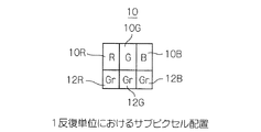
次に添付図面を参照して本発明によるカラー表示装置の実施例を詳細に説明する。本発明によるカラー表示装置の実施例は、液晶表示装置であり、本実施例の液晶表示装置は、画像プロセッサ、タイミングコントローラなど表示に必要な機能をすべて含む。図1を参照すると、1反復単位10は、3個の原色RGBを表示する副画素10R、10B、10Gと、これらの原色10R、10B、10Gとは異なる1つの補助色を表示する副画素12R、12B、12Gを含む。
Embodiments of a color display device according to the present invention will now be described in detail with reference to the accompanying drawings. An embodiment of the color display device according to the present invention is a liquid crystal display device, and the liquid crystal display device of this embodiment includes all functions necessary for display such as an image processor and a timing controller. Referring to FIG. 1, one repeating
図1A、1Bは、1反復単位におけるサブピクセルの配置を示す。図1Aは、本発明による配置を示し、図1Bは、比較のために従来技術による配置を示す。以下では、副画素と、その副画素が表示する色とを同一の参照符号で示す。1反復単位が画面の横方向および縦方向に所定の数だけ配置されることにより、1画面が構成される。本実施例の補助色12R、12B、12Gは、輝度情報に対応する色である。以下では、補助色データとは、階調(輝度)データのことを言う。1反復単位内の原色の各々を表示する副画素10R、10B、10Gと、補助色を表示する副画素12R、12B、12Gとは、それぞれ対応している。
1A and 1B show the arrangement of subpixels in one repeating unit. FIG. 1A shows an arrangement according to the invention, and FIG. 1B shows an arrangement according to the prior art for comparison. Hereinafter, the sub-pixel and the color displayed by the sub-pixel are denoted by the same reference symbol. One screen is configured by arranging a predetermined number of one repeating unit in the horizontal and vertical directions of the screen. The
本実施例では、図1Bに示す通常の、RGBの三原色で構成されているピクセル14の下に、図1Aに示すようにサブピクセル12R、12B、12Gをそれぞれ配置する。以下では、サブピクセル12R、12B、12Gの表示する色を灰色と呼び、Gr(Gray)と表現する。サブピクセル12R、12B、12Gは、単純に白から黒の範囲で変化し、輝度変化のみを表示する。サブピクセル12R、12B、12Gは、対応するRGB三原色10R、10B、10Gのそれぞれの階調、すなわち明るさに補正を加え、RGB三原色10R、10B、10Gの個々の色およびRGB三原色10R、10B、10Gを組み合わせた色に対して、色補正やコントラスト強調などを行なうものである。
In the present embodiment, sub-pixels 12R, 12B, and 12G are arranged below the
サブピクセル12R、12B、12Gの位置のカラーフィルタは白色である。白色フィルタは、必ずしも必要ではないが、液晶表示装置の光源であるバックライトの分光特性に合った白色フィルタを適切に選択して、設けることが好ましい。
The color filter at the position of the
LCDにおける、サブピクセルヘの印加電圧、すなわち階調電圧と実際に表示される輝度、すなわち明るさとの関係の一例を図2に示す。図2は、印加電圧に対する透過率の曲線16を表したものであり、横軸が印加電圧、縦軸が明るさを示す。印加電圧が低い時に透過率が高くなるため、NW(ノーマリーホワイト)と呼ばれる。逆の特性の場合はNB(ノーマリーブラック)と呼ばれる。明るさは、液晶の透過率で決まるため、縦軸は明るさに等価である。本図より、同じ電圧幅18a、18bに対する明るさの幅20a、20bを比較すると、幅20aの方が、幅20bより大きいことがわかる。印加電圧に対する明るさの曲線16は、図3に示すように、RGB三原色のそれぞれによって異なる。図3は、RGB三原色のそれぞれについて、印加電圧に対する明るさの曲線22a、22b、22cを示す。横軸が印加電圧、縦軸が明るさを示す。なお、既述のように、刻まれる(分圧される)数によって、表示できる色数が決定される。
FIG. 2 shows an example of the relationship between the voltage applied to the sub-pixel, that is, the gradation voltage, and the actually displayed luminance, that is, the brightness in the LCD. FIG. 2 shows a
本実施例では、図1Aに示すようにRGB三原色のそれぞれにGrayのサブピクセルを配置することで、RGB三原色の各階調の間をさらに補完することを可能とする。図4に、本発明の概念を示す。図4は、Grサブピクセルにより生成される階調を示し、曲線24は、RGB三原色のうちの一色、赤についてのサブピクセルの透過率であり、曲線26は、この赤に対応するGrサブピクセルの透過率である。原色および補助色のサブピクセルには電圧V1〜V6が印加され、原色のサブピクセルの透過率T1〜T6が得られる。補助色については、曲線26上に示す透過率26a、26b、26c等が得られる。
In the present embodiment, as shown in FIG. 1A, the gray subpixels are arranged in each of the RGB primary colors, thereby further complementing the gradations of the RGB primary colors. FIG. 4 shows the concept of the present invention. FIG. 4 shows the tone produced by the Gr subpixel, where
曲線24上の黒丸は、曲線24で示す電圧対透過率特性と、曲線26で示す電圧対透過率特性が加算されたときの電圧対透過率特性を示す。たとえば、曲線26上の電圧対透過率特性点26cは、曲線24で示す電圧対透過率特性26上に3個の特性点26c1、26c2、26c3を生成する。すなわち原色のサブピクセル透過特性点の間(図4ではT3とT4)が曲線26の透過率点26a、26b、26cとの組み合わせにより、さらに3分割され、実質階調数が増加するわけである。これを曲線26の特性点から出る矢印で示す。特性点26a、26b、26cにより原色のサブピクセル透過特性点の間に3階調が生成されるわけである。本図では、図が複雑化することを防ぐために、一部の矢印のみを示す。
A black circle on the
RGBそれぞれのサブピクセルの電圧対透過率特性と、Grayのサブピクセルの電圧対透過率特性を組み合わせて、実質的な階調数を増加させる。そして、たとえば、円28に囲まれた部分が、透過率T3と透過率T4との間に最終的に生成される全部の階調データを表す。すなわち、実線が交差するポイントの間がさらに、特性点26a3、26b2、26c1のように3分割される。
By combining the voltage vs. transmittance characteristics of each RGB sub-pixel and the voltage vs. transmittance characteristics of the Gray sub-pixel, the substantial number of gradations is increased. For example, the portion surrounded by the
図4の例では、本来は、透過率T1〜T6という6階調しかない輝度(階調)数に対して、補助ピクセルで、各階調間に3階調分を作り出し、三原色のサブピクセル、図4の例では赤のサブピクセルの階調の間を補完している。本来は6階調T1〜T6であったが、3階調のGrサブピクセルを持つことで15階調が加えられ、21階調数を得られることになる。図4では、その階調のすべてを表示しているわけではなく、階調3と階調4の間をとくに詳しく表示しており、ここが3分割されている。 In the example of FIG. 4, for the number of luminance (gradation) having only six gradations of transmittances T1 to T6, the auxiliary pixel creates three gradations between each gradation, and the three primary color sub-pixels, In the example of FIG. 4, the red sub-pixel gradation is complemented. Originally 6 gradations T1 to T6, but having 3 gradations of Gr sub-pixels, 15 gradations are added and 21 gradations can be obtained. In FIG. 4, not all of the gradations are displayed, but the details between gradations 3 and 4 are displayed in detail, and this is divided into three.
すなわち、6階調のそれぞれの間(T1-T2、T2-T3、T3-T4、T4-T5、T5-T6)がさらに3分割されるため、本来の6階調に加えて、3x5=15の明暗(階調)を得ることができる。したがって、本来あるレベルとその間に得られた明暗を合わせて21レベルの階調が得られる。別の例として、一般的な256階調(8ビット)のLCDドライバを用いてRGBを階調制御し、16階調のGrピクセルを補完用に用いるとすれば、従来のRGB三原色方式では、256×256×256=約1667万色であるのに対して、本発明のようなRGB三原色+Grサブピクセル方式では、256×16×256×16×256×16=約687億色となる。 That is, since each of the six gradations (T1-T2, T2-T3, T3-T4, T4-T5, T5-T6) is further divided into three, in addition to the original six gradations, 3 × 5 = 15 Can be obtained. Therefore, 21 levels of gradation can be obtained by combining the original level and the light and darkness obtained in the meantime. As another example, if RGB is controlled using a general 256-gradation (8-bit) LCD driver and 16-gradation Gr pixels are used for complementation, the conventional RGB three primary colors method Whereas 256 × 256 × 256 = about 16.67 million colors, the RGB three primary colors + Gr sub-pixel method as in the present invention results in 256 × 16 × 256 × 16 × 256 × 16 = about 68.7 billion colors.
このように、Grサブピクセルを用いる方式では、電圧の分解能に関してLCDドライバに特別な仕様を要求することなく、容易に得られる色数を増やすことができる。たとえば、約10億色をRGB三原色のサブピクセルだけで得ようとすると、l024階調(10ビット)の分解能を持つLCDドライバが必要となる。一方、本方式では、64階調(6ビット)のLCDドライバを用いて、Grサブピクセル駆動時に、64階調を16階調に粗く分割して使用すればよい。 As described above, in the method using the Gr sub-pixel, the number of colors that can be easily obtained can be increased without requiring a special specification from the LCD driver regarding the voltage resolution. For example, if you want to obtain about 1 billion colors with only RGB sub-pixels, you need an LCD driver with a resolution of l024 gradations (10 bits). On the other hand, in this method, a 64 gradation (6 bits) LCD driver is used, and the 64 gradations may be roughly divided into 16 gradations when the Gr subpixel is driven.
また、Grサブピクセルヘの階調電圧の基になるデータを、RGBそれぞれに対応して変更、すなわち調整することで、RGB三原色の電圧対透過率曲線を別々に制御できる。なお、これらのGrサブピクセルのデータは、LCDドライバに画像(階調)データを供給するタイミングコントローラ内に格納することができる。 Further, by changing, that is, adjusting, the data that is the basis of the gradation voltage to the Gr subpixel corresponding to each RGB, it is possible to separately control the voltage vs. transmittance curve of the three primary colors of RGB. The Gr subpixel data can be stored in a timing controller that supplies image (gradation) data to the LCD driver.
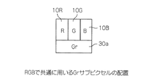
さらにLCDドライバやシステム全体の構成を簡単にして、製造のコストを低減するために、図5A、5Bに示すGrのサブピクセル配置を用いてもよい。図5A、5Bは、Grのサブピクセル30a、30bをRGBのサブピクセル10R、10G、10Bで共通に用いる場合の1反復単位を示す。3個のRGBのサブピクセル10R、10G、10Bに対して、1個のGrのサブピクセル30a、30bを配置している。図5Aは、RGBおよびGrのサブピクセル10R、10G、10B、30aが水平方向に配列されたものであり、図5Bは、RGBおよびGrのサブピクセル10R、10G、10B、30bが正方格子状に配列されたものである。この方式では、ピクセルの構造が簡単になり、LCDの製造プロセスが短くなる。反面、RGBのサブピクセル10R、10G、10Bのそれぞれを独立して制御することが困難になる。
Further, in order to simplify the configuration of the LCD driver and the entire system and reduce the manufacturing cost, the Gr subpixel arrangement shown in FIGS. 5A and 5B may be used. FIGS. 5A and 5B show one repeating unit when the
基本動作は、図1Aに示すGrのサブピクセルと同様である。ただし、図5A、5Bの例では、RGBのうちの複数の色が発光しているときは、RGBのそれぞれに対応させて制御することはせずに、RGB全体で得られた色に対する補正を行う。したがって、得られる色数は、図1Aに示すGrのサブピクセルのようにRGBそれぞれにGrサブピクセルを設けた場合の、256×16×256×16×256×16=約687億色に対して、256×256×256×16=約2億7千万色となる。 The basic operation is the same as that of the Gr subpixel shown in FIG. 1A. However, in the examples of FIGS. 5A and 5B, when a plurality of colors of RGB are emitting light, the correction for the colors obtained for the entire RGB is performed without performing control corresponding to each of RGB. Do. Therefore, the number of colors obtained is 256 × 16 × 256 × 16 × 256 × 16 = about 68.7 billion colors when Gr subpixels are provided for each RGB like the Gr subpixel shown in FIG. 1A. 256 x 256 x 256 x 16 = about 270 million colors.
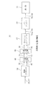
次に、図1、図5に示すGrのサブピクセルに供給される輝度情報の生成方法について、図6により説明する。図6は、本発明の一実施例に係る液晶表示装置32の構成を示すブロック図である。液晶表示装置32においては、表示部34に表示される輝度情報は、装置32に入力される輝度信号36である。なお、本発明では、輝度信号を装置内部で生成することとしてもよい。液晶表示装置32は、画像プロセッサ38を含み、このプロセッサ38は、表示部34で表示する画像データ36、37、すなわち輝度信号36および色差信号37を入力されて、当該画像データ36、37を処理して、RGBデータ40を生成した後、生成したRGBデータ40および輝度信号36を出力する。装置32は、さらにタイミングコントローラ42およびLCDドライバ44とを含み、これらは、入力された画像データ40を表示部34で表示可能なデータに変換する。以下では、これを詳細に説明する。
Next, a method of generating luminance information supplied to the Gr subpixels shown in FIGS. 1 and 5 will be described with reference to FIG. FIG. 6 is a block diagram showing the configuration of the liquid
画像プロセッサ38は、輝度信号36および色差信号37を入力されて、画像プロセッサ38内において、従来の方法によりRGBデータ40を生成するとともに、輝度信号36をそのまま取り出し、タイミングコントローラ42に転送する。画像プロセッサ38に入力される輝度信号36および色差信号37は、輝度信号(Y)36および色差信号(Cr, Cb)37のサンプリング周波数の比が4:2:2の信号である。輝度信号(Y)36の比率が4である。画像プロセッサ38は、この信号を、サンプリング周波数の比が4:4:4のRGBデータ40に変換して出力する。さらに、画像プロセッサ38は、入力された輝度信号36をそのまま出力する。
The
画像プロセッサ38が出力する輝度信号36は、補助色用サブピクセルのデータとして用いられる。このように複雑なアルゴリズムを用いることなく、補助色用のデータをタイミングコントローラ42に供給できる。
The
プロセッサ38とタイミングコントローラ42との間に設けられたLVDS(low voltage differential signaling)送信部46とLVDS受信部48は、数100Mビット/秒以上の高速な信号伝送を実現するために,入出力すべき信号の振幅を数100mVに減らして低振幅化して伝送するものである。低振幅としたことで雑音の影響を受けやすくなるが,シングルエンド伝送ではなく差動伝送を採用することにより、この影響を減らしている。また、低振幅のため、放射ノイズが低減し、EMI対策が取られている。
An LVDS (low voltage differential signaling)
上述のように、画像プロセッサ38に入力された内の輝度信号36をそのまま用いることで、極めて簡単に補助色サブピクセル用の階調信号36を得ることができる。また、この信号を通常のRGB三原色サブピクセルデータ40とは別に送ることで、RGBに関しては、従来の標準化されたLVDS信号40をタイミングコントローラ42は受け取ることができる。
As described above, by using the
図7は、タイミングコントローラ42およびLVDS受信部48のブロック図である。LVDS受信部48は、2種類のLVDS受信部48-1、48-2を有し、LVDS受信部48-2は補助色サブピクセル用データ36を受信し、LVDS受信部48-1はRGBサブピクセルのデータ40を受信する。補助色が必要ない場合は、LVDS受信部48-1のみを動かせばよい。LVDS受信部48-1、48-2は、データ36、40をタイミングコントローラ42に出力し、タイミングコントローラ42は、受信したデータ36、40を、データ変換部50において、表示部34でライン表示ができるように、ライン順に従って並べ替え、すなわち変換を行う。データ変換部50は、変換するとともに、表示の不具合、たとえば下記の階調のズレが起こらないようにデータ36、40を、ルックアップテーブル(LUT;Look Up Table)52を用いて補正する機能を有する。
FIG. 7 is a block diagram of the
補正は以下の理由から行われる。タイミングコントローラ42が受け取った補助色サブピクセルデータ36が、そのまま実際のLCDパネル34で表示するには適切でない場合も考えられる。たとえば、VT特性(印加電圧対透過率特性)は、RGBのそれぞれで異なるため、そのままでは階調のずれが生じる。そこで、RGBの各原色に応じて補正する必要がある。このような場合に、LUT 52にデータ36、40のそれぞれの特性の情報、具体的にはデータ36、40に対する階調電圧などをあらかじめ書き込んでおき、データ変換部50は、信号線50bを介して必要なデータをLUT 52から得て、表示する色合いに応じて補正する。補正に必要なデータは、LUT 52に格納されており、必要な場合に補正が行われる。LUT 52には、パネルの特性に応じた補正データが記憶されている。
The correction is performed for the following reason. There may be a case where the auxiliary
データ変換部50は、変換および補正を行ったデータを、信号線50aを介して出力部54に出力する。出力部54は、入力されたデータを、RSDS(商標、Reduced Swing Differential Signaling)方式やmini-LVDS方式にしたがって、図6に示すLCDドライバ44内のソースドライバ44a(図8に示す)に、信号線54aを介して出力する。タイミングコントローラ42は、LCDドライバ44内のゲートドライバ44b(図8に示す)を駆動する信号54bも出力する。
The
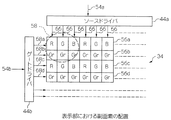
図8に、LCDドライバ44と表示部34の構成を示す。図8Aは、本発明に係るLCDドライバ44と表示部34の構成を示し、図8Bは、比較のために、補助色サブピクセルを有しない従来のLCDドライバ70a、70bと表示部72の構成を示す。図8A、8Bには、比較のために、本発明と従来技術における1画素を構成するサブピクセルの範囲を、点線の丸58、60で示す。
FIG. 8 shows the configuration of the
プロセッサ38からRGB画像データおよび補助色データを受けたタイミングコントローラ42は、RGB画像データおよび補助色データのそれぞれのデジタル階調信号を、信号線54aを介してLCDドライバ44のソースドライバ44aに出力する。当該データを受けたソースドライバ44aが、各RGBサブピクセル10R、10G、10Bおよび補助色サブピクセル12R、12G、12Bにアナログの階調電圧を供給する。
Receiving the RGB image data and the auxiliary color data from the
供給する順番に関しては、1行目56aのRGBサブピクセル10R、10G、10Bを、ゲートドライバ44bが、ゲート線68aにより選択して、RGB画像データをソースドライバ44aが、データ線66を介して各RGBサブピクセル10R、10G、10Bに供給する。次のタイミングで、2行目56bの補助色サブピクセル12R、12G、12Bを、ゲートドライバ44bがゲート線68bにより選択して、補助色データをソースドライバ44aが、データ線66を介して各補助色サブピクセル12R、12G、12Bに供給する。以下、これを、ライン56c、56d、・・・と順に、1画面分繰り返す。
As for the supply order, the
本実施例によれば、カラー表示装置の原色自体の階調数を増加させることなく、実質的に多階調が得られるカラー表示装置およびカラー表示方法を提供できる。また、単純化した方法で、補助色のデータを生成できる。 According to the present embodiment, it is possible to provide a color display device and a color display method capable of substantially obtaining multiple gradations without increasing the number of gradations of the primary color itself of the color display device. Further, auxiliary color data can be generated by a simplified method.
本発明の液晶表示装置は、とくにLCDテレビなど、高い純度や複雑な色を表現する必要のあるLCDパネルに適している。しかし、これ以外にも、携帯電話やカーナビゲーションシステム、DVDプレイヤなどにも応用可能である。 The liquid crystal display device of the present invention is particularly suitable for LCD panels such as LCD televisions that need to express high purity and complex colors. However, other than this, it can be applied to a mobile phone, a car navigation system, a DVD player, and the like.
図9に、図5Bの副画素を用いたときのLCDドライバ64a、64bと表示部34の構成を示す。本図の場合、データを供給する順番は、1行目62aのRGサブピクセル10R、10Gを、ゲートドライバ64bがゲート線74aにより選択して、RG画像データをソースドライバ64aが、各RGサブピクセル10R、10Gにデータ線76を介して供給する。次のタイミングで、2行目62bのBサブピクセル10Bと補助色サブピクセル30bを、ゲートドライバ64bがゲート線74bにより選択して、B画像データと補助色データをソースドライバ64aが、Bサブピクセル10Bと補助色サブピクセル30bにデータ線76を介して供給する。以下、これを、ライン62c、62d、62e・・・と、1画面分繰り返す。本実施例によっても、カラー表示装置の原色自体の階調数を増加させることなく、実質的に多階調が得られる。また、単純化した方法で、補助色のデータを生成できる。
FIG. 9 shows the configuration of the
10、14 反復単位
10R、10B、10G、12R、12B、12G 副画素(サブピクセル)
16、22a、22b、22c 曲線
32 液晶表示装置
34 表示部
38 画像プロセッサ
42 タイミングコントローラ
44 LCDドライバ
50 データ変換部
52 ルックアップテーブル(LUT)
10, 14 repeat units
10R, 10B, 10G, 12R, 12B, 12G Sub-pixel
16, 22a, 22b, 22c curves
32 Liquid crystal display
34 Display
38 Image processor
42 Timing controller
44 LCD driver
50 Data converter
52 Look-up table (LUT)
Claims (16)
プロセッサは、輝度信号と色差信号とに応じて、各原色データを生成するとともに、タイミングコントローラへ、前記輝度信号と、前記各原色データを出力し、
前記タイミングコントローラは、前記輝度信号から補助色データを生成するとともに、前記各原色データと前記補助色データとをソースドライバへ出力することを特徴とする表示装置制御方法。 In a display device control method for controlling a color display device that displays three or more primary colors and at least one auxiliary color different from the primary colors,
The processor generates each primary color data according to the luminance signal and the color difference signal, and outputs the luminance signal and each primary color data to the timing controller,
The timing controller generates auxiliary color data from the luminance signal and outputs each primary color data and the auxiliary color data to a source driver.
表示部で表示すべき前記輝度情報および色差情報を入力されまたは生成し、
該輝度情報および該色差情報から前記原色データを生成し、
該輝度情報および該原色データを前記表示部で表示可能なデータに変換することを特徴とするカラー表示方法。 The color display method according to claim 5,
The luminance information and color difference information to be displayed on the display unit is input or generated,
Generating the primary color data from the luminance information and the color difference information;
A color display method, wherein the luminance information and the primary color data are converted into data that can be displayed on the display unit.
該データ処理部は、該表示部で表示すべき前記輝度情報および色差情報を入力されまたは生成し、該輝度情報および該色差情報から前記原色データを生成し、該輝度情報および該原色データを前記表示制御部に出力し、
該表示制御部は、該入力された輝度情報および原色データを前記表示部で表示可能なデータに変換することを特徴とするカラー表示装置。 The color display device according to claim 13, wherein the device includes a display unit, a data processing unit, and a display control unit,
The data processing unit receives or generates the luminance information and color difference information to be displayed on the display unit, generates the primary color data from the luminance information and the color difference information, and converts the luminance information and the primary color data to the Output to the display controller,
The display control unit converts the input luminance information and primary color data into data that can be displayed on the display unit.
Priority Applications (2)
| Application Number | Priority Date | Filing Date | Title |
|---|---|---|---|
| JP2007092526A JP2008250065A (en) | 2007-03-30 | 2007-03-30 | Color display device and color display method |
| US12/057,875 US8159509B2 (en) | 2007-03-30 | 2008-03-28 | Color display device and method for reproducing color with an increased number of gradation levels |
Applications Claiming Priority (1)
| Application Number | Priority Date | Filing Date | Title |
|---|---|---|---|
| JP2007092526A JP2008250065A (en) | 2007-03-30 | 2007-03-30 | Color display device and color display method |
Publications (1)
| Publication Number | Publication Date |
|---|---|
| JP2008250065A true JP2008250065A (en) | 2008-10-16 |
Family
ID=39793495
Family Applications (1)
| Application Number | Title | Priority Date | Filing Date |
|---|---|---|---|
| JP2007092526A Pending JP2008250065A (en) | 2007-03-30 | 2007-03-30 | Color display device and color display method |
Country Status (2)
| Country | Link |
|---|---|
| US (1) | US8159509B2 (en) |
| JP (1) | JP2008250065A (en) |
Families Citing this family (4)
| Publication number | Priority date | Publication date | Assignee | Title |
|---|---|---|---|---|
| TWI316218B (en) * | 2005-12-23 | 2009-10-21 | Innolux Display Corp | A liquid crystal display device and a method for driving the same |
| JP5998982B2 (en) * | 2013-02-25 | 2016-09-28 | 株式会社Jvcケンウッド | Video signal processing apparatus and method |
| US20160217766A1 (en) * | 2015-01-23 | 2016-07-28 | Dell Products, Lp | System and Method for Sub-Pixel Color Management |
| CN105654887B (en) * | 2016-01-27 | 2019-12-06 | 京东方科技集团股份有限公司 | data input unit, data input method, source electrode driving circuit and display device |
Family Cites Families (20)
| Publication number | Priority date | Publication date | Assignee | Title |
|---|---|---|---|---|
| JPH0365865A (en) | 1989-08-03 | 1991-03-20 | Fujitsu General Ltd | Output circuit for muse decoder |
| JPH03201695A (en) | 1989-12-27 | 1991-09-03 | Matsushita Electric Ind Co Ltd | Projecting display device |
| JP3201695B2 (en) | 1994-03-22 | 2001-08-27 | 株式会社吉野工業所 | Dispensing cap |
| KR0139152B1 (en) | 1994-04-07 | 1998-05-15 | 김광호 | A signal processing apparatus and the method for 2 panel lcd projector |
| JP3684740B2 (en) * | 1997-01-24 | 2005-08-17 | セイコーエプソン株式会社 | YUV-RGB digital conversion circuit, and image display apparatus and electronic apparatus using the same |
| JP3416570B2 (en) | 1999-05-20 | 2003-06-16 | シャープ株式会社 | Address type image display device |
| JP3406536B2 (en) | 1999-05-20 | 2003-05-12 | シャープ株式会社 | Address type image display device |
| JP3805150B2 (en) | 1999-11-12 | 2006-08-02 | コーニンクレッカ フィリップス エレクトロニクス エヌ ヴィ | Liquid crystal display |
| JP2002229505A (en) * | 2001-01-31 | 2002-08-16 | Nec Corp | Display device |
| EP1497820A4 (en) | 2002-04-11 | 2009-03-11 | Genoa Color Technologies Ltd | Color display devices and methods with enhanced attributes |
| KR100943273B1 (en) * | 2003-05-07 | 2010-02-23 | 삼성전자주식회사 | Method and apparatus for converting a 4-color, and organic electro-luminescent display device and using the same |
| JP2005249820A (en) * | 2004-03-01 | 2005-09-15 | Seiko Epson Corp | Color correcting circuit and image display device with the same |
| KR20070003937A (en) * | 2004-03-19 | 2007-01-05 | 코닌클리케 필립스 일렉트로닉스 엔.브이. | Active matrix display with pixel to pixel non-uniformity improvement at low luminance level |
| JP2006171049A (en) | 2004-12-13 | 2006-06-29 | Matsushita Electric Ind Co Ltd | Display apparatus, display method, program and recording medium |
| JP2006259135A (en) | 2005-03-16 | 2006-09-28 | Sharp Corp | Display apparatus and color filter substrate |
| JP2006267826A (en) | 2005-03-25 | 2006-10-05 | Optrex Corp | Display device |
| KR101166827B1 (en) * | 2005-05-10 | 2012-07-19 | 엘지디스플레이 주식회사 | Apparatus and method for driving liquid crystal display device |
| JP5070204B2 (en) | 2005-05-20 | 2012-11-07 | サムスン エレクトロニクス カンパニー リミテッド | Multiple primary color sub-pixel rendering with metamer filtering |
| KR101256965B1 (en) | 2005-06-22 | 2013-04-26 | 엘지디스플레이 주식회사 | LCD and driving method thereof |
| KR100760943B1 (en) * | 2006-01-25 | 2007-09-21 | 엘지.필립스 엘시디 주식회사 | Apparatus and method driving for mobile display device |
-
2007
- 2007-03-30 JP JP2007092526A patent/JP2008250065A/en active Pending
-
2008
- 2008-03-28 US US12/057,875 patent/US8159509B2/en not_active Expired - Fee Related
Also Published As
| Publication number | Publication date |
|---|---|
| US20080238952A1 (en) | 2008-10-02 |
| US8159509B2 (en) | 2012-04-17 |
Similar Documents
| Publication | Publication Date | Title |
|---|---|---|
| US8310426B2 (en) | Apparatus and method for driving liquid crystal display panel with data driver including gamma correction circuitry and drive circuitry | |
| KR101588336B1 (en) | Method for processing data and display apparatus for performing the method | |
| US8390652B2 (en) | Drive control circuit and drive control method for color display device | |
| US6765551B2 (en) | Column electrode driving circuit for use with image display device and image display device incorporating the same | |
| JP5278730B2 (en) | CONTROLLER, HOLD TYPE DISPLAY, ELECTRONIC DEVICE, SIGNAL ADJUSTMENT METHOD FOR HOLD TYPE DISPLAY | |
| WO2011102343A1 (en) | Display device | |
| WO2012053404A1 (en) | Display device | |
| JP6396978B2 (en) | Timing controller and display device | |
| US20090303248A1 (en) | System and method for dithering video data | |
| KR20060130231A (en) | Gamma correction circuit, display panel, and display having them | |
| KR20110026225A (en) | Data processing device, display system having the same and method of processing data | |
| WO2011036916A1 (en) | Display device and display method therefor | |
| US8228319B2 (en) | Display device and controller driver for improved FRC technique | |
| KR20210082855A (en) | Mura compensation circuit and driving apparatus for display having the same | |
| KR100457281B1 (en) | The plasma disaplay device and display method | |
| KR20160099162A (en) | Display apparatus and method of driving the same | |
| KR101222961B1 (en) | Liquid crystal display device and method for driving the same | |
| JP2008250065A (en) | Color display device and color display method | |
| JP6551230B2 (en) | Signal generation device and image display device | |
| CN113808550B (en) | Device applicable to brightness enhancement in display module | |
| JP2009186800A (en) | Display method and flicker determination method of display device | |
| WO2011065092A1 (en) | Liquid crystal display device, television receiver, and display method for liquid crystal display device | |
| JP3466832B2 (en) | Color image display | |
| WO2017051768A1 (en) | Display device and colour space expansion method | |
| JP4892804B2 (en) | Sequential color display device |
Legal Events
| Date | Code | Title | Description |
|---|---|---|---|
| A621 | Written request for application examination |
Free format text: JAPANESE INTERMEDIATE CODE: A621 Effective date: 20080811 |
|
| A711 | Notification of change in applicant |
Free format text: JAPANESE INTERMEDIATE CODE: A712 Effective date: 20090114 |
|
| A977 | Report on retrieval |
Free format text: JAPANESE INTERMEDIATE CODE: A971007 Effective date: 20090123 |
|
| A131 | Notification of reasons for refusal |
Free format text: JAPANESE INTERMEDIATE CODE: A131 Effective date: 20090203 |
|
| A521 | Request for written amendment filed |
Free format text: JAPANESE INTERMEDIATE CODE: A523 Effective date: 20090403 |
|
| RD02 | Notification of acceptance of power of attorney |
Free format text: JAPANESE INTERMEDIATE CODE: A7422 Effective date: 20090403 |
|
| A131 | Notification of reasons for refusal |
Free format text: JAPANESE INTERMEDIATE CODE: A131 Effective date: 20090811 |
|
| A521 | Request for written amendment filed |
Free format text: JAPANESE INTERMEDIATE CODE: A523 Effective date: 20091009 |
|
| A02 | Decision of refusal |
Free format text: JAPANESE INTERMEDIATE CODE: A02 Effective date: 20100105 |