JP2008192560A - Rotary input device, and portable electronic apparatus - Google Patents
Rotary input device, and portable electronic apparatus Download PDFInfo
- Publication number
- JP2008192560A JP2008192560A JP2007028298A JP2007028298A JP2008192560A JP 2008192560 A JP2008192560 A JP 2008192560A JP 2007028298 A JP2007028298 A JP 2007028298A JP 2007028298 A JP2007028298 A JP 2007028298A JP 2008192560 A JP2008192560 A JP 2008192560A
- Authority
- JP
- Japan
- Prior art keywords
- input device
- rotary input
- rotating body
- rotary
- axial direction
- Prior art date
- Legal status (The legal status is an assumption and is not a legal conclusion. Google has not performed a legal analysis and makes no representation as to the accuracy of the status listed.)
- Pending
Links
Images


Landscapes
- Switches With Compound Operations (AREA)
Abstract
Description
本発明は、携帯電子機器等に搭載される回転式入力装置及び携帯電子機器に関する。 The present invention relates to a rotary input device and a portable electronic device mounted on a portable electronic device or the like.
従来、携帯電話、電子辞書等の携帯電子機器において、音量等の調節や項目選択等の用途に、ロータリーエンコーダを使用した回転式入力装置(例えば、特許文献1参照。)が採用されている。 2. Description of the Related Art Conventionally, in a portable electronic device such as a mobile phone or an electronic dictionary, a rotary input device using a rotary encoder (see, for example, Patent Document 1) is used for applications such as volume adjustment and item selection.
これは、回転軸を有する回転体をユーザが操作して回転させた際の回転変位量を、回転軸に設けられたロータリーエンコーダによって電気的パルスに変換し、当該電子機器の各種制御量として用いるものである。 This is because a rotational displacement amount when a rotating body having a rotating shaft is operated and rotated by a user is converted into an electrical pulse by a rotary encoder provided on the rotating shaft and used as various control amounts of the electronic device. Is.
本入力装置は、回転体の操作量と制御量とがほぼ比例関係にあるため、ユーザは直感的な操作が可能であるという利点がある。
ところで、携帯電子機器は多機能化に伴い、音量、液晶画面等の表示部の明度、コントラスト、画面スクロール等の連続量を伴う制御パラメータが増加すると同時に、更なる小型化が要請されている。
しかしながら、特許文献1の回転式入力装置は、基本的に1つの機能の制御量調整しかできないため、上述のすべての機能に対して直感的操作を可能にするためには、当該入力装置を複数設ける必要がある。これは上述の小型化の要請に対する妨げとなる。
By the way, with the increase in functionality of portable electronic devices, control parameters with continuous amounts such as volume, brightness of a display unit such as a liquid crystal screen, contrast, screen scrolling, and the like are increased, and further miniaturization is required.
However, since the rotary input device of
一方、上述のような諸機能を統合した環境設定画面をボタンキー等の入力装置を操作して表示部に表示し、上下左右の移動キー等を利用して上述のような制御を行う方式も採用されているが、所望のキーを連続して押さなければならず、操作が直感的でないという問題がある。さらに、環境設定画面の呼び出し方法自体がユーザにわかりにくい場合も多く、ユーザにとっての利便性は必ずしも充分でない。 On the other hand, there is a method in which an environment setting screen in which various functions as described above are integrated is displayed on a display unit by operating an input device such as a button key, and the above control is performed using up / down / left / right movement keys. Although adopted, there is a problem that a desired key must be continuously pressed, and the operation is not intuitive. In addition, the environment setting screen calling method itself is often difficult for the user to understand, and the convenience for the user is not always sufficient.
本発明は上記事情に鑑みて成されたものであり、複数の機能制御を直感的に行うことを可能としつつ、省スペースで組み込み可能な回転式入力装置及び携帯電子機器を提供することを目的とする。 The present invention has been made in view of the above circumstances, and an object thereof is to provide a rotary input device and a portable electronic device that can be incorporated in a space-saving manner while allowing a plurality of function controls to be performed intuitively. And
本発明は、制御信号を発生させることによって複数の機能を制御可能な回転式入力装置であって、回転軸を有し、前記回転軸の軸線方向に所定の範囲だけ摺動可能に配置された回転体と、前記回転軸に設けられ、前記回転体の回転変位量を電気信号に変換することによって前記制御信号を発生させる回転変位量変換部と、前記回転体の前記軸線方向における位置を検知する検知部と、前記検知部で検知される前記回転体の位置に基づいて、前記複数の機能のうち制御対象となる1の機能を択一的に選択する制御対象決定部とを備えることを特徴とする。 The present invention is a rotary input device capable of controlling a plurality of functions by generating a control signal, having a rotary shaft, and arranged so as to be slidable within a predetermined range in the axial direction of the rotary shaft. A rotating body, a rotational displacement amount conversion unit that is provided on the rotating shaft and generates the control signal by converting the rotational displacement amount of the rotating body into an electrical signal, and detects the position of the rotating body in the axial direction And a control target determining unit that alternatively selects one function to be controlled among the plurality of functions based on the position of the rotating body detected by the detection unit. Features.
本発明の回転入力装置によれば、回転体の軸線方向における位置を調節することで、検知部と制御対象決定部とによって制御対象が選択され、回転体を回転させることによって回転変位量変換部で回転変位量に対応した制御信号が発生する。 According to the rotary input device of the present invention, the control object is selected by the detection unit and the control target determination unit by adjusting the position of the rotary body in the axial direction, and the rotational displacement amount conversion unit is rotated by rotating the rotary body. Thus, a control signal corresponding to the rotational displacement amount is generated.
前記検知部は、前記回転軸に設けられた可動子と、前記回転軸の軸線方向に離間して配置され、前記回転体を前記軸線方向に摺動したときに前記可動子と電気的に接触する固定子とを有するものでもよい。この場合、簡素な構造で複数の機能制御を行うことができる。 The detection unit is arranged to be separated from the mover provided on the rotating shaft in the axial direction of the rotating shaft, and is in electrical contact with the mover when the rotating body slides in the axial direction. It may have a stator. In this case, a plurality of function controls can be performed with a simple structure.
本発明の回転式入力装置は、前記回転軸の外周に、前記回転軸の軸線と平行にかつ周方向に一定の間隔おきに設けられた複数の係合溝と、前記係合溝と係合する弾性係合部材とを有し、前記回転体が所定の変位量回転するごとに、前記係合溝と前記弾性係合部材との係合が外れて前記回転体を回転させる際の抵抗力が開放され、前記回転体に回転感触を発生させる回転感触発生部をさらに備えてもよい。この場合、ユーザは操作量を容易に把握かつ調整することができ、ユーザの操作感を向上させることができる。 The rotary input device according to the present invention includes a plurality of engagement grooves provided on the outer periphery of the rotation shaft in parallel with the axis of the rotation shaft and at regular intervals in the circumferential direction, and the engagement with the engagement grooves. Each time the rotating body rotates by a predetermined displacement amount, a resistance force when the engaging groove and the elastic engaging member are disengaged to rotate the rotating body. May be further provided with a rotation feeling generating section that generates a rotation feeling on the rotating body. In this case, the user can easily grasp and adjust the operation amount, and the user's operational feeling can be improved.
本発明の回転式入力装置は、前記回転軸の周方向にわたって設けられた嵌合溝を有し、前記回転体を前記軸線方向に摺動したときに、前記嵌合溝と前記検知部とが嵌合することによって前記回転体に摺動感触を発生させる摺動感触発生部をさらに備えるものでもよい。 The rotary input device of the present invention has a fitting groove provided over the circumferential direction of the rotating shaft, and when the rotating body is slid in the axial direction, the fitting groove and the detection unit are It may further include a sliding feel generating portion that generates a sliding feel on the rotating body by fitting.
この場合、回転体を軸線方向に摺動させて制御対象の機能を選択する際に、嵌合溝と検知部とが嵌合する位置に回転軸を位置決めすることができる。また、嵌合溝と検知部とが嵌合する際に前記回転体に摺動感触が発生するので、ユーザは選択された制御対象の機能を容易に把握することができ、ユーザの操作感を向上させることができる。 In this case, when the function to be controlled is selected by sliding the rotating body in the axial direction, the rotating shaft can be positioned at a position where the fitting groove and the detection unit are fitted. In addition, when the fitting groove and the detection unit are fitted, a sliding feel is generated in the rotating body, so that the user can easily grasp the function of the selected control target, and the user's operational feeling can be improved. Can be improved.
本発明の携帯電子機器は、本発明の回転式入力装置を備えることを特徴とする。
本発明の携帯電子機器によれば、回転体の回転操作と回転軸の軸線方向への摺動とによって、単一の入力装置によって複数の機能を直感的に操作することができる。
A portable electronic device according to the present invention includes the rotary input device according to the present invention.
According to the portable electronic device of the present invention, a plurality of functions can be intuitively operated by a single input device by rotating the rotating body and sliding the rotating shaft in the axial direction.
前記携帯電子機器は、表示部を有する第1筐体と、操作部を有する第2筐体と、前記第1筐体と前記第2筐体とを折りたたみ可能に連結するヒンジとを有し、前記回転式入力装置は前記ヒンジの一方の端部に、前記ヒンジと前記回転軸とが同軸となるように配置されているものでもよい。
この場合、回転式入力装置をヒンジと一体に設けることができるので、回転式入力装置を設けるスペースを別に設ける必要がなく、さらに携帯電子機器を小型化することができる。
The portable electronic device includes a first casing having a display unit, a second casing having an operation unit, and a hinge that foldably connects the first casing and the second casing, The rotary input device may be arranged at one end of the hinge so that the hinge and the rotation shaft are coaxial.
In this case, since the rotary input device can be provided integrally with the hinge, it is not necessary to provide a separate space for providing the rotary input device, and the portable electronic device can be further downsized.
本発明の回転式入力装置によれば、ユーザが直感的に調整操作を行うことを可能としつつ、1つの入力装置によって複数の機能を制御することができる。
また、本発明の携帯電子機器によれば、多機能を有しつつ、小型でかつ直感的に操作可能な携帯電子機器を構成することができる。
According to the rotary input device of the present invention, a plurality of functions can be controlled by one input device while allowing the user to perform an adjustment operation intuitively.
In addition, according to the portable electronic device of the present invention, it is possible to configure a portable electronic device that has multiple functions and is small and intuitively operable.
以下、本発明の第1実施形態の回転式入力装置及び携帯電子機器について、図1から図4を参照して説明する。
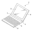
図1は本実施形態の回転式入力装置1を搭載した電子辞書(携帯電子機器)2を示す斜視図である。電子辞書2は、図示しないバックライトを有する表示部3を備えた第1筐体4と、操作キー(操作部)5を有する第2筐体6と、第1筐体4と第2筐体6とを折りたたみ可能に連結するヒンジ7とを備えて構成されている。回転式入力装置1は、ヒンジ7の右側の端部にヒンジ7と一体となって組み込まれている。
Hereinafter, a rotary input device and a portable electronic device according to a first embodiment of the present invention will be described with reference to FIGS.
FIG. 1 is a perspective view showing an electronic dictionary (portable electronic device) 2 equipped with a
図2(a)は、通常時の回転式入力装置1を示す図である。回転式入力装置1は、回転軸8を有するツマミ(回転体)9と、回転軸8に設けられたロータリーエンコーダ(変位量変換部)10と、回転軸8の側面付近に設けられた検知部11とを備えて構成されている。
FIG. 2A shows the
ツマミ9は、樹脂等で形成され、回転軸8と、回転軸8と同軸に設けられた略円筒形のツマミ本体12とから構成されている。
The
ロータリーエンコーダ10は、インクリメンタル方式の公知の構成のものであり、回転軸8のツマミ本体12から所定の距離離間した外周面上に形成された回転接点部13と、回転接点部13に接触して設けられた固定接点14とを有して構成される。
The
回転接点部13には、樹脂で形成された回転軸8の外周面に所定の長さの帯状の金属片15が、周方向に一定の間隔おきに全周にわたって回転軸8の軸線と平行に配置されている。固定接点14は、先端が回転接点部13に接触する棒状又は板状の導体からなる部材であり、その基端は回転軸8に沿うように設けられた回路基板16に接続されている。
In the rotary contact portion 13, a strip-
回転接点部13よりさらにツマミ本体12から離間した回転軸8上の所定の位置には、金属等の導体で形成された円盤状の可動子17が設けられている。
回路基板16上には、固定接点14と並んで設けられた複数の接触端子(固定子)18A、18B、18Cが、可動子17と接触可能に回転軸8の軸線方向に離間して配置されている。検知部11は、可動子17と各接触端子18A、18B、18Cとから構成されている。
A disc-like
On the
回転軸8は、ツマミ本体12より径の小さい円筒形のケース19の両端を、回転軸8とケース19とが同軸となるように貫通しており、ロータリーエンコーダ10、検知部11、及び回路基板16はケース19内に収納されている。
The
ケース19を貫通した回転軸8の端部にはケース19と同一径のストッパ20が設けられており、ツマミ9が回転軸8の軸線方向に所定の範囲摺動可能に構成されている。ケース19及びストッパ20は、ヒンジ7内に収容、固定されている。
A
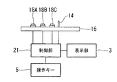
図3は電子辞書2の構成を示すブロック図である。回路基板16上の固定接点14及び各接触端子18A、18B、18Cは、第2筐体6内に設けられた制御部(制御対象決定部)21と接続されている。制御部21は、半導体装置等で構成され、表示部3及び操作キー5とも接続されており、電子辞書2の全体的な制御を行う。
FIG. 3 is a block diagram showing the configuration of the
上記のように構成された回転式入力装置の動作について、図2(a)及び図2(b)を参照して説明する。
図2(a)に示すように、ツマミ本体12がケース19に接触する位置P1まで押し込まれた標準時において、可動子17はストッパ20側の接触端子18Aと当接している。この状態においては回転式入力装置1から発せられる信号は、制御部21において表示部3の画面スクロールの制御信号として認識される。
The operation of the rotary input device configured as described above will be described with reference to FIGS. 2 (a) and 2 (b).
As shown in FIG. 2A, the
ユーザがツマミ本体12を回転させると、回転軸8に設けられた回転接点部13が回転する。それに伴って金属片15と、各金属片15の間の樹脂が交互に固定接点14に接触し、所定の回転変位量ごとに、固定接点14のオンとオフとが繰り返される。ロータリーエンコーダ10はこのオン及びオフに伴って発生するパルスと位相とを利用して、アナログ量である回転軸8の回転変位量を、向きを伴ったデジタル信号に変換し、回路基板16を介して制御部21に送る。
When the user rotates the
制御部21では検知部11における可動子17と各接触端子18A、18B、18Cとの接触状況に基づいて、上述のように当該信号を画面スクロールに関する制御信号として取り扱い、当該信号によって示された向き及び量に従って、表示部3に表示された辞書の検索項目の内容等の表示をスクロール移動させる。
The
図4に示すように、ツマミ本体12の左端をP3の位置まで引くと、図2(b)に示すようにストッパ20がケース19に接触し、可動子17は、最もツマミ本体12側の接触端子18Cと接触する。
As shown in FIG. 4, when the left end of the
この状態でユーザがツマミ本体12を回転させると、上述のように、向きと量とを有するデジタル信号がロータリーエンコーダ10によって生成され、回路基板16を通して制御部21に送られる。このとき制御部21では、検知部11の接触状況に基づいて、当該デジタル信号を電子辞書2の音量に関する制御信号として取り扱い、当該制御信号の向き及び量に基づいて音量の調節を行う。
When the user rotates the knob
また、上記と同様の操作で、ユーザが可動子17と接触端子18Bとが接触する位置P2にツマミ9を摺動させると、制御部21ではロータリーエンコーダ10の生成した信号を、表示部3のバックライトの明度に関する制御信号として取り扱い、当該制御信号の向き及び量に基づいてバックライトの明度調節を行う。
Further, when the user slides the
本実施形態の回転式入力装置1及び電子辞書2によれば、ツマミ9を回転軸8の軸線方向に摺動させて、可動子17と接触する接触端子18A、18B、18Cを変更することで、検知部11によってツマミ9の回転軸8の軸線方向における位置が検知され、当該位置に基づいて、制御部21によって制御の対象となる機能が選択決定される。従って、複数の種類のアナログ量の制御を1つの回転式入力装置1で行うことができ、多機能を有する電子辞書であっても、小型化を図ることができる。
According to the
また、諸機能の調節のためにユーザが環境設定画面等を表示部3に表示させる必要がなく、ツマミ本体12を摺動して、可動子17の位置を調節して回転することによって直接制御ができるので、ユーザの操作ステップ数を大幅に削減して、操作を簡便にすることができる。
Further, there is no need for the user to display an environment setting screen or the like on the
また、ツマミ本体12の回転量によって、対象となる機能の制御量を調節することができるので、操作キー5による調節に比べて直感的に調節を行うことができる。従って、ユーザの操作感を向上させることができる。
さらに、回転式入力装置1は、ヒンジ7の一端にヒンジ7とほぼ一体に取付けられているので、回転入力装置1を設置するためのスペースを新たに確保する必要がなく、携帯電子機器の更なる小型化に資することができる。
Further, since the control amount of the target function can be adjusted by the rotation amount of the
Furthermore, since the
次に、本発明の第2実施形態について図5を参照して説明する。本実施形態と上述の第1実施形態との異なるところは、回転軸に回転感触発生部及び摺動感触発生部が設けられている点、検知部の形状、及び回転軸と検知部との接触の態様である。
なお、上述の第1実施形態と同様の構成要素については、同一の符号を付し、重複する説明を省略する。
Next, a second embodiment of the present invention will be described with reference to FIG. The difference between this embodiment and the first embodiment described above is that the rotation shaft is provided with a rotation feeling generator and a sliding feel generator, the shape of the detector, and the contact between the rotation shaft and the detector. It is an aspect.
In addition, about the component similar to the above-mentioned 1st Embodiment, the same code | symbol is attached | subjected and the overlapping description is abbreviate | omitted.
図5(a)は本実施形態の回転式入力装置31の模式図である。図5(a)に示すように、本実施形態のツマミ32において、回転軸33のロータリーエンコーダ10と検知部34の間に位置する部分には、回転軸33の軸線に直交する断面が略V字状の所定の長さの係合溝35が、軸線と平行に、かつ一定の間隔おきに全周にわたって設けられている。係合溝35はロータリーエンコーダの金属片15一枚に対して一本設けてもよいし、金属片15一枚に対して所定の複数本、例えば3本設けてもよい。
FIG. 5A is a schematic diagram of the
ケース19内の係合溝35に対向する所定の位置には、樹脂等で形成された略長方形の舌片の先端に係合歯(不図示)を有する弾性係合部材36が、係合歯が係合溝35に係合するように設けられており、係合溝35と弾性係合部材36とで回転感触発生部37が構成されている。
回転軸33の係合溝35よりストッパ20側の部位には、回転軸33に平行な断面が略V字状の嵌合溝38A、38Bが、全周にわたって軸線と直交するように設けられており、各嵌合溝38A、38Bと検知部34とから、摺動感触発生部40が構成されている。
At a predetermined position facing the
Fitting
本実施形態の検知部34はケース19の内面上に設けられた2個のスイッチ39A、39Bを有する。各スイッチ39A、39Bは、それぞれケース19の内面上に固定された基部41A、41Bと、各基部41A、41Bに設けられて図示しないバネ等の付勢手段により上方に突出し、かつ上下に移動可能に設けられた略円錐形の突出部42A、42Bとを有して構成されている。
また、固定接点14及び各スイッチ39A、39Bは、図示しない回路基板を介して、第1実施形態と同様に制御部21に接続されている
The
The fixed
上記のように構成された回転式入力装置31の動作について、図5(a)から図5(c)を参照して以下に説明する。
まず図5(a)に示す標準時は、ツマミ本体12がケース19に接触する位置P1まで押し込まれている。このとき、回転軸33上の嵌合溝38A、38Bのいずれもスイッチ39Aよりストッパ20側に位置しているため、各スイッチの突出部42A、42Bは、いずれも回転軸33の外側面に押圧されて、オンの状態になっている。この状態において、制御部21はロータリーエンコーダ10から発せられる制御信号を、表示部3の画面スクロールに関する制御信号として取り扱う。
The operation of the
First, at the standard time shown in FIG. 5A, the
ユーザがツマミ本体12を回転させると、ツマミ本体12を所定の回転角だけ回転させるごとに、係合溝35と弾性係合部材36の係合歯とが係脱を繰り返すため、回転軸33を回転させる際の抵抗感が所定の回転変位量ごとに解放されて、回転感触としてのクリック感をユーザに感じさせる。同時に、ロータリーエンコーダ10で制御信号が生成されて制御部21に送られる。制御部21は、第1実施形態と同様に表示部3の表示をスクロールさせる制御を行う。
When the user rotates the
図5(a)の状態から、ユーザがツマミ本体12を軸線方向に引くと、図5(b)に示すように、ツマミ本体12の左端が位置P2に達したところでスイッチ39Aと嵌合溝38Aとが対向して突出部42Aが嵌合溝38A内に突出する。このとき、摺動感触発生部40のスイッチ39Aと嵌合溝38Aとが嵌合することによって、ツマミ本体12に摺動感触としてのクリック感が発生し、スイッチ39Aはオフ状態となる。この状態において、制御部21はロータリーエンコーダ10で生成される制御信号を、表示部3のバックライトの明度に関する制御信号として取り扱う。
When the user pulls the knob
さらにツマミ本体12を軸線方向に引くと、スイッチ39Aが嵌合溝38Aから離脱する。その後、図5(c)に示すようにツマミ本体12の左端が位置P3に達すると、嵌合溝38Aがスイッチ39Bと嵌合するとともに、嵌合溝38Bがスイッチ39Aと嵌合して、ツマミ本体12に摺動感触としてのクリック感が発生する。このとき、各スイッチはいずれも突出部42A、42Bが嵌合溝38A、38B内に突出し、オフ状態となる。この状態において、制御部21はロータリーエンコーダ10で生成される制御信号を、音量に関する制御信号として取り扱う。
When the
本実施形態の回転式入力装置31によれば、ユーザがツマミ本体12を所定角度に対応する変位量回転させるごとに、回転感触発生部37の係合溝35と弾性係合部材36の係合歯とが係脱を繰り返すことによって回転感触としてのクリック感が発生し、ユーザに認知される。従って、ユーザは操作量をより明確に認識可能になるとともに、操作量の調節も容易となるため、操作感を向上させることができる。
According to the
また、ツマミ本体12を回転軸33の軸線方向に摺動させて制御対象の機能を選択する際には、摺動感触発生部40の嵌合溝38A、38Bと、各スイッチ39A、39Bの突出部42A、42Bとが嵌合して、摺動感触としてのクリック感が発生するので、ユーザは所望の機能が選択されたことを容易に認識することができる。同時に、回転軸33を、制御対象機能を選択するための位置に確実に位置決めすることができる。
Further, when the
さらに、嵌合溝38A、38Bが略V字状に、各スイッチの突出部42A、42Bが略円錐状に形成され、かつ突出部42A、42Bは付勢手段によって回転軸33側に上下方向に移動可能に突出しているため、嵌合位置では確実に嵌合しつつ、回転軸33を摺動させ続けることによって容易に嵌合を離脱させることが可能である。従って、制御対象機能の選択を、ツマミ32を摺動させることによってスムーズに行うことができる。
Further, the
以上、本発明の実施形態について説明したが、本発明の技術範囲は上記実施の形態に限定されるものではなく、本発明の趣旨を逸脱しない範囲において種々の変更を加えることが可能である。
例えば、上記実施形態においては、回転変位量変換部として、インクリメンタル方式のロータリーエンコーダを用いた例を説明したが、これに代えて、アブソリュート方式のロータリーエンコーダを用いてもよい。
While the embodiments of the present invention have been described above, the technical scope of the present invention is not limited to the above-described embodiments, and various modifications can be made without departing from the spirit of the present invention.
For example, in the above-described embodiment, an example in which an incremental rotary encoder is used as the rotational displacement amount conversion unit has been described. However, instead of this, an absolute rotary encoder may be used.
また、上記実施形態においては、検知部を、回転軸に設けられた可動子及び接触端子等の機構から構成した例を説明したが、これに代えて、透過光等により回転軸のケース端部からの突出量を検知する機構等を検知部とし、検知部の検知した当該突出量に基に、制御部が制御対象の機能をソフトウェアプログラムによって決定するように回転式入力装置を構成することも可能である。 In the above-described embodiment, the example in which the detection unit is configured by a mechanism such as a mover and a contact terminal provided on the rotating shaft has been described. Instead, the case end of the rotating shaft is transmitted by transmitted light or the like. It is also possible to configure the rotary input device so that the control unit determines the function to be controlled by the software program based on the protrusion amount detected by the detection unit, such as a mechanism that detects the amount of protrusion from the detection unit. Is possible.
さらに、回転変位量変換部、回転感触発生部、及び検知部の回転軸上の位置も、上記実施形態の態様に限定されない。これらの機構は、回転接点部と固定接点、係合溝と係合部材の係合歯、及び可動子と接触端子とが、それぞれツマミ本体の摺動範囲内において常に連携するように構成さえすれば、上記各機構をツマミ本体側からいかなる順番で設置することも可能である。
また、検知部の接触端子やスイッチの個数も上記実施形態に限定されず、制御対象とする機能項目の数に応じて自由に設定することができる。
Furthermore, the positions of the rotational displacement amount conversion unit, the rotation feeling generation unit, and the detection unit on the rotation axis are not limited to the above-described embodiments. These mechanisms are configured so that the rotary contact portion and the fixed contact, the engagement groove and the engagement teeth of the engagement member, and the movable element and the contact terminal are always linked within the sliding range of the knob body. For example, the mechanisms can be installed in any order from the knob body side.
Further, the number of contact terminals and switches of the detection unit is not limited to the above embodiment, and can be freely set according to the number of function items to be controlled.
加えて、ストッパの位置も上記実施形態のようにケースの外側に限定されず、ストッパをケース内部に設けた中仕切りに当接するように設け、ツマミ本体がケースから一定距離以上離間しないように構成してもよい。 In addition, the position of the stopper is not limited to the outside of the case as in the above embodiment, and the stopper is provided so as to abut against a partition provided inside the case, so that the knob body is not separated from the case by a certain distance or more. May be.
また、本発明の携帯電子機器は実施形態の電子辞書には限定されない。本発明の回転式入力装置は、ヒンジを有する携帯電話等にも適用可能である。また、省スペースという効果は若干失われるが、ヒンジを有さない携帯電子機器に適用することも可能である。 The portable electronic device of the present invention is not limited to the electronic dictionary of the embodiment. The rotary input device of the present invention is also applicable to a mobile phone having a hinge. Further, although the effect of space saving is slightly lost, it can be applied to a portable electronic device having no hinge.
1、31 回転式入力装置
2 電子辞書(携帯電子機器)
3 表示部
4 第1筐体
5 操作キー(操作部)
6 第2筐体
7 ヒンジ
8、33 回転軸
9、32 ツマミ(回転体)
10 ロータリーエンコーダ(回転変位量変換部)
11、34 検知部
17 可動子
18A,18B、18C 接触端子(固定子)
21 制御部(制御対象決定部)
35 係合溝
36 弾性係合部材
37 回転感触発生部
38A、38B 嵌合溝
40 摺動感触発生部
1, 31
3
6
10 Rotary encoder (rotational displacement converter)
11, 34
21 Control unit (control target determination unit)
35
Claims (6)
回転軸を有し、前記回転軸の軸線方向に所定の範囲だけ摺動可能に配置された回転体と、
前記回転軸に設けられ、前記回転体の回転変位量を電気信号に変換することによって前記制御信号を発生させる回転変位量変換部と、
前記回転体の前記軸線方向における位置を検知する検知部と、
前記検知部で検知される前記回転体の位置に基づいて、前記複数の機能のうち制御対象となる1の機能を択一的に選択する制御対象決定部と、
を備えることを特徴とする回転式入力装置。 A rotary input device capable of controlling a plurality of functions by generating a control signal,
A rotating body having a rotating shaft and disposed so as to be slidable within a predetermined range in the axial direction of the rotating shaft;
A rotational displacement amount conversion unit that is provided on the rotation shaft and generates the control signal by converting the rotational displacement amount of the rotating body into an electrical signal;
A detection unit that detects a position of the rotating body in the axial direction;
A control target determining unit that alternatively selects one function to be controlled among the plurality of functions based on the position of the rotating body detected by the detection unit;
A rotary input device comprising:
前記回転軸に設けられた可動子と、
前記回転軸の軸線方向に離間して配置され、前記回転体を前記軸線方向に摺動したときに前記可動子と電気的に接触する複数の固定子と、
を有することを特徴とする請求項1に記載の回転式入力装置。 The detector is
A mover provided on the rotating shaft;
A plurality of stators which are arranged apart from each other in the axial direction of the rotating shaft and which come into electrical contact with the mover when the rotating body is slid in the axial direction;
The rotary input device according to claim 1, comprising:
前記係合溝と係合する弾性係合部材とを有し、
前記回転体が所定の変位量回転するごとに、前記係合溝と前記弾性係合部材との係合が外れて前記回転体を回転させる際の抵抗力が開放され、前記回転体に回転感触を発生させる回転感触発生部をさらに備えることを特徴とする請求項1又は2のいずれか1項に記載の回転式入力装置。 A plurality of engaging grooves provided on the outer periphery of the rotating shaft in parallel to the axis of the rotating shaft and at regular intervals in the circumferential direction;
An elastic engagement member that engages with the engagement groove;
Each time the rotating body rotates by a predetermined displacement amount, the engagement force between the engaging groove and the elastic engaging member is disengaged to release the resistance force when rotating the rotating body, and the rotating body feels to rotate. The rotary input device according to claim 1, further comprising: a rotation feeling generating unit that generates the rotation.
前記回転体を前記軸線方向に摺動したときに、前記嵌合溝と前記検知部とが嵌合することによって前記回転体に摺動感触を発生させる摺動感触発生部をさらに備えることを特徴とする請求項1又は3のいずれか1項に記載の回転式入力装置。 Having a fitting groove provided over the circumferential direction of the rotating shaft;
When the rotating body is slid in the axial direction, a sliding feel generating section is further provided that generates a sliding feel on the rotating body by fitting the fitting groove and the detection section. The rotary input device according to any one of claims 1 and 3.
表示部を有する第1筐体と、
操作部を有する第2筐体と、
前記第1筐体と前記第2筐体とを折りたたみ可能に連結するヒンジとを有し、
前記回転式入力装置は前記ヒンジの一方の端部に、前記ヒンジと前記回転軸とが同軸となるように配置されていることを特徴とする請求項5に記載の携帯電子機器。 The portable electronic device is
A first housing having a display unit;
A second housing having an operation unit;
A hinge that foldably connects the first housing and the second housing;
6. The portable electronic device according to claim 5, wherein the rotary input device is disposed at one end of the hinge so that the hinge and the rotation shaft are coaxial.
Priority Applications (1)
| Application Number | Priority Date | Filing Date | Title |
|---|---|---|---|
| JP2007028298A JP2008192560A (en) | 2007-02-07 | 2007-02-07 | Rotary input device, and portable electronic apparatus |
Applications Claiming Priority (1)
| Application Number | Priority Date | Filing Date | Title |
|---|---|---|---|
| JP2007028298A JP2008192560A (en) | 2007-02-07 | 2007-02-07 | Rotary input device, and portable electronic apparatus |
Publications (1)
| Publication Number | Publication Date |
|---|---|
| JP2008192560A true JP2008192560A (en) | 2008-08-21 |
Family
ID=39752446
Family Applications (1)
| Application Number | Title | Priority Date | Filing Date |
|---|---|---|---|
| JP2007028298A Pending JP2008192560A (en) | 2007-02-07 | 2007-02-07 | Rotary input device, and portable electronic apparatus |
Country Status (1)
| Country | Link |
|---|---|
| JP (1) | JP2008192560A (en) |
-
2007
- 2007-02-07 JP JP2007028298A patent/JP2008192560A/en active Pending
Similar Documents
| Publication | Publication Date | Title |
|---|---|---|
| US7765495B2 (en) | Mobile terminal having rotating input device and method for operating the mobile terminal | |
| EP2159775A1 (en) | Stationary remote control transmitter | |
| EP2159774A1 (en) | Remote control transmitter | |
| US8164009B2 (en) | Control knob which operates multiple systems | |
| EP2159776A1 (en) | Stationary remote control transmitter | |
| JP2010257051A (en) | Rotary input device and electronic equipment | |
| JP2004070654A (en) | Portable electronic equipment | |
| CN109074184B (en) | User interface device for touch screen of portable communication device | |
| WO1994017494A2 (en) | Data input device | |
| JP2007235956A (en) | Mobile communication terminal | |
| JP2011238061A (en) | Input device | |
| JP2004320772A (en) | Menu setting apparatus and its method for sliding type mobile communication terminal | |
| JP2004359102A (en) | On-vehicle electrical equipment control device | |
| JP2008192560A (en) | Rotary input device, and portable electronic apparatus | |
| JP2009004322A (en) | Operation device and operation system | |
| EP1772881B1 (en) | Rotary push button with direction marker | |
| JP4214874B2 (en) | Electronics | |
| JP2009295494A (en) | Multidirectional operation switching device | |
| JP5412812B2 (en) | Input device, control device, control system, and handheld device | |
| JP2014059682A (en) | Input device and input system | |
| CN107182963B (en) | Electric fishing line reel | |
| JP4347117B2 (en) | Operating device and electronic device | |
| JP2008071643A (en) | Switch device | |
| CN107614205B (en) | Power tool user interface | |
| JP2011192413A (en) | Operation switch and portable terminal |