JP2008191786A - Program management device, program management method and program - Google Patents
Program management device, program management method and program Download PDFInfo
- Publication number
- JP2008191786A JP2008191786A JP2007023383A JP2007023383A JP2008191786A JP 2008191786 A JP2008191786 A JP 2008191786A JP 2007023383 A JP2007023383 A JP 2007023383A JP 2007023383 A JP2007023383 A JP 2007023383A JP 2008191786 A JP2008191786 A JP 2008191786A
- Authority
- JP
- Japan
- Prior art keywords
- program
- system resource
- application
- resource usage
- component
- Prior art date
- Legal status (The legal status is an assumption and is not a legal conclusion. Google has not performed a legal analysis and makes no representation as to the accuracy of the status listed.)
- Pending
Links
Images


Classifications
-
- G—PHYSICS
- G06—COMPUTING; CALCULATING OR COUNTING
- G06F—ELECTRIC DIGITAL DATA PROCESSING
- G06F9/00—Arrangements for program control, e.g. control units
- G06F9/06—Arrangements for program control, e.g. control units using stored programs, i.e. using an internal store of processing equipment to receive or retain programs
- G06F9/44—Arrangements for executing specific programs
- G06F9/445—Program loading or initiating
- G06F9/44505—Configuring for program initiating, e.g. using registry, configuration files
Landscapes
- Engineering & Computer Science (AREA)
- Software Systems (AREA)
- Theoretical Computer Science (AREA)
- Physics & Mathematics (AREA)
- General Engineering & Computer Science (AREA)
- General Physics & Mathematics (AREA)
- Stored Programmes (AREA)
Abstract
Description
本発明は、プログラムの部品の切り替えによるシステム資源使用量を加味したシステム資源の検査を行う技術に関するものである。 The present invention relates to a technique for inspecting system resources in consideration of the amount of system resources used by switching program components.
従来、アプリケーションをカスタマイズするための技術やアップグレードをするための技術が存在する。特に、プラグイン機構によってプラットフォームの機能を拡張することが可能なシステムが知られている(例えば、特許文献1参照)。 Conventionally, there are technologies for customizing applications and technologies for upgrading. In particular, a system capable of extending the functions of a platform by a plug-in mechanism is known (for example, see Patent Document 1).
また、ソフトウェアモジュールのアップグレードをアプリケーションの変更を伴わずに行うシステムが知られている(例えば、特許文献2参照)。 There is also known a system that upgrades software modules without changing applications (for example, see Patent Document 2).
さらに、アプリケーションを動的にインストールするシステムにおいて、インストールに際してシステム資源の空きを検査してインストールの可否を制御するシステムが知られている(例えば、特許文献3参照)。 Furthermore, in a system that dynamically installs applications, a system that checks availability of system resources at the time of installation and controls the availability of installation is known (for example, see Patent Document 3).
しかしながら、特許文献1及び2に開示される発明では、ソフトウェアモジュールを切り替える際に、ソフトウェアモジュールが使用するシステム資源の増加によるシステムへの影響が考慮されていなかった。このため、ソフトウェアモジュールを切り替える前には動作していたシステムが、ソフトウェアモジュールを切り替えた後にはシステム資源の不足により動作しなくなるという問題があった。
However, in the inventions disclosed in
また、特許文献3に開示される発明では、アプリケーションのインストールに際してのシステム資源の検査は行われている。しかしながら、アプリケーションが使用するアプリケーション部品の切り替えに関しては、アプリケーション部品が使用するシステム資源が考慮されておらず、適切なシステム資源の検査が行われず、同様な問題があった。
In the invention disclosed in
そこで、本発明の目的は、プログラムの部品の切り替えによるシステム資源使用量の変化を加味したシステム資源の検査を行うことを可能とすることにある。 Therefore, an object of the present invention is to make it possible to inspect system resources in consideration of changes in system resource usage due to switching of program components.
本発明のプログラム管理装置は、プログラムの部品の切り替えによるシステム資源使用量の増減値を算出する第1の算出手段と、前記増減値を加味した前記プログラムのシステム資源使用量を算出する第2の算出手段と、前記第2の算出手段により算出された前記プログラムのシステム資源使用量に基づいて、前記プログラムの部品の切り替え後におけるシステム資源使用量が所定のシステム資源の使用可能範囲に収まるか否かを判定する判定手段とを有することを特徴とする。
本発明のプログラム管理方法は、プログラム管理装置によるプログラム管理方法であって、プログラムの部品の切り替えによるシステム資源使用量の増減値を算出する第1の算出ステップと、前記増減値を加味した前記プログラムのシステム資源使用量を算出する第2の算出ステップと、前記第2の算出ステップにより算出された前記プログラムのシステム資源使用量に基づいて、前記プログラムの部品の切り替え後におけるシステム資源使用量が所定のシステム資源の使用可能範囲に収まるか否かを判定する判定ステップとを含むことを特徴とする。
本発明のプログラムは、プログラム管理装置によるプログラム管理方法をコンピュータに実行させるためのプログラムであって、プログラムの部品の切り替えによるシステム資源使用量の増減値を算出する第1の算出ステップと、前記増減値を加味した前記プログラムのシステム資源使用量を算出する第2の算出ステップと、前記第2の算出ステップにより算出された前記プログラムのシステム資源使用量に基づいて、前記プログラムの部品の切り替え後におけるシステム資源使用量が所定のシステム資源の使用可能範囲に収まるか否かを判定する判定ステップとをコンピュータに実行させることを特徴とする。
The program management apparatus according to the present invention includes: a first calculation unit that calculates an increase / decrease value of a system resource usage amount by switching program components; and a second calculation unit that calculates a system resource usage amount of the program in consideration of the increase / decrease value. Whether or not the system resource usage after switching the parts of the program falls within a predetermined system resource usable range based on the system resource usage of the program calculated by the calculation means and the second calculation means Determining means for determining whether or not.
The program management method of the present invention is a program management method by a program management device, wherein the program takes into account the first calculation step of calculating an increase / decrease value of system resource usage by switching parts of the program, and the program taking the increase / decrease value into consideration A second calculation step for calculating the system resource usage amount of the program, and a system resource usage amount after switching the parts of the program based on the system resource usage amount of the program calculated by the second calculation step. And a determination step of determining whether or not the system resources can be used.
A program according to the present invention is a program for causing a computer to execute a program management method by a program management apparatus, and includes a first calculation step of calculating an increase / decrease value of a system resource usage amount by switching parts of the program; A second calculation step of calculating a system resource usage amount of the program in consideration of the value, and a system resource usage amount of the program calculated by the second calculation step, after switching the parts of the program And a determination step of determining whether or not the system resource usage is within a usable range of a predetermined system resource.
本発明においては、プログラムの部品の切り替えによるシステム資源使用量の増減値を算出し、上記増減値を加味した当該プログラムのシステム資源使用量を算出する。そして、算出された当該プログラムの部品の切り替え後におけるシステム資源使用量に基づいて、当該プログラムの部品の切り替え後におけるシステム資源使用量が所定のシステム資源の使用可能範囲に収まるか否かを判定するように構成している。従って、本発明によれば、プログラムの部品の切り替えによるシステム資源使用量の変化を加味したシステム資源の検査を行うことが可能となる。 In the present invention, the increase / decrease value of the system resource usage amount by switching the parts of the program is calculated, and the system resource usage amount of the program in consideration of the increase / decrease value is calculated. Then, based on the calculated system resource usage after switching the parts of the program, it is determined whether the system resource usage after switching the parts of the program falls within a predetermined system resource usable range. It is configured as follows. Therefore, according to the present invention, it is possible to inspect system resources taking into account changes in system resource usage due to switching of program components.
以下、本発明を適用した好適な実施形態を、添付図面を参照しながら詳細に説明する。 DESCRIPTION OF EXEMPLARY EMBODIMENTS Hereinafter, preferred embodiments to which the invention is applied will be described in detail with reference to the accompanying drawings.
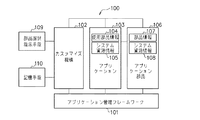
図1は、本発明の実施形態に係るアプリケーション管理システムの機能構成を概略的に示す図である。なお、図1に示すアプリケーション管理システムの構成は飽くまでも一例であり、その実行環境が搭載されていれば、いかなる機器でも実現可能であり、また、その構成要素を複数の機器に分散して実現するようにしてもよい。図1に示すアプリケーション管理システムは、本発明のプログラム管理装置の一適用例となる構成である。 FIG. 1 is a diagram schematically showing a functional configuration of an application management system according to an embodiment of the present invention. Note that the configuration of the application management system shown in FIG. 1 is merely an example, and any device can be realized as long as the execution environment is installed, and the components are distributed to a plurality of devices. You may do it. The application management system shown in FIG. 1 has a configuration as an application example of the program management apparatus of the present invention.
図1において、100はアプリケーション管理システムである。101は、アプリケーションプログラム(以下、単にアプリケーションと称す)を管理するアプリケーション管理フレームワークである。
In FIG. 1,
102は、部品の切り替えを行うことによってアプリケーションをカスタマイズする機能を担うカスタマイズ機構である。
103は、アプリケーションである。個々のアプリケーション103は、アプリケーション管理フレームワーク101の管理単位である。アプリケーション管理フレームワーク101は、一乃至複数のアプリケーション103をアプリケーション管理システム100内にインストールする。そして、アプリケーション103の開始、終了及びアンインストールといったライフサイクル全般に渡る管理を行う。
アプリケーション103は、当該アプリケーション103が使用する部品(以下、アプリケーション部品と称す)に係る情報を使用部品情報104として保持している。さらに、アプリケーション103は、当該アプリケーション103のシステム資源使用量を示す情報を、システム資源情報105として保持している。
The
106は、アプリケーション部品である。アプリケーション103はこれを使用することができる。個々のアプリケーション部品106もまたアプリケーション管理フレームワーク101の管理単位である。
アプリケーション管理フレームワーク101は、一乃至複数のアプリケーション部品106をアプリケーション管理システム100内にインストール或いはアンインストールする。
The
アプリケーション部品106は、当該アプリケーション部品106に係る情報を部品情報107として保持している。さらに、アプリケーション部品106は、当該アプリケーション部品106のシステム資源使用量を示す情報を、システム資源情報108として保持している。
The
109は、部品切り替え時にアプリケーション部品106の選択を指示する部品選択指示手段である。110は、後述するアプリケーション部品106の各種管理情報を記憶する記憶手段である。
図2は、アプリケーション管理システム100のハードウェア構成を示すブロック図である。
FIG. 2 is a block diagram illustrating a hardware configuration of the
アプリケーション管理システム100は、主な構成要素として、コントローラ部201、操作部206、表示部207、ハードディスク208及びLAN制御部209等を備える。コントローラ部201は、アプリケーション管理システム100の制御を司る。操作部206は、キーボードやマウス等の入力手段によって構成される。LAN制御部209は、ネットワークを介してアプリケーション管理システム100が外部装置と通信するための制御部である。
The
コントローラ部201は、CPU202、ROM203、RAM204及びタイマ205等を備える。CPU202が実行する各種プログラムやプログラムが必要とするデータ等は、予めROM203に記憶されている。また、一部のプログラムやデータはハードディスク208に予め格納されており、RAM204に読み出して実行することが可能である。タイマ205は、各種時間を計測するのに用いられる。なお、本実施形態に係るアプリケーション管理システム100のハードウェア構成は、図2に挙げた構成に限らず、これらの構成の一部を備えていないものであってもよいし、他の構成を備えるものであってもよい。
The
図1の部品選択指示手段は、例えば、操作部206及び表示部207によって構成される。記憶手段110は、例えばRAM204の一部記憶領域に相当する構成である。カスタマイズ機構102及びアプリケーション管理フレームワーク101は、例えば、CPU202がハードディスク208からRAM204に該当するプログラムをロードし、CPU202がこれを実行することにより実現する構成である。また、アプリケーション管理フレームワーク101は、後述するアプリケーション一覧情報300を格納しておくためのRAM204の一部記憶領域も含む。アプリケーション103及びアプリケーション部品106は、ハードディスク208内に格納されている。
1 includes, for example, an
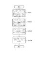
次に、アプリケーション103がアプリケーション部品106に係る情報をカスタマイズ機構102に対して登録する手順を、図3を参照しながら説明する。図3は、アプリケーション103がアプリケーション部品106に係る情報をカスタマイズ機構102に対して登録する手順を示すフローチャートである。アプリケーション部品106に係る情報の登録手順は、アプリケーション103のインストール或いはアプリケーション103の開始によって実行される。
Next, a procedure in which the
まず、アプリケーション103は、当該アプリケーション103を他のアプリケーションと識別するためのアプリケーションIDを、アプリケーション管理フレームワーク101から取得する(ステップS1101)。
First, the
アプリケーション103は、アプリケーション管理システム100内に複数個インストールすることが可能である。アプリケーション管理フレームワーク101は、各々のアプリケーション103に対してアプリケーションIDを与え、アプリケーションIDを用いて夫々を識別することが可能である。
A plurality of
図9は、アプリケーション管理システム100内にインストールされたアプリケーション103の一覧を示すアプリケーション一覧情報300を模式的に示す図である。アプリケーション一覧情報300は、アプリケーション管理フレームワーク101によって生成され、アプリケーション管理フレームワーク101内において格納される情報である。
FIG. 9 is a diagram schematically showing application list information 300 indicating a list of
アプリケーション管理フレームワーク101は、アプリケーション103をインストールするとき、当該アプリケーション103のアプリケーション名301と当該アプリケーション103に付与されたアプリケーションID302とを対応付ける。この対応付けの一覧情報がアプリケーション一覧情報300として扱われ、アプリケーション管理フレームワーク101内部において格納される。
When installing the
アプリケーション103からの要求があると、アプリケーション管理フレームワーク101は、アプリケーション一覧情報300を参照し、要求に該当するアプリケーションID302を返す。即ち、アプリケーション103は、自らのアプリケーション名を含むアプリケーションIDの取得要求を発行する。アプリケーション管理フレームワーク101は、その要求に含まれるアプリケーション名に対応付けられるアプリケーションIDをアプリケーション103に対して返す。
When there is a request from the
次に、アプリケーション103は、カスタマイズ機構102のオブジェクトを取得する(ステップS1102)。そして、アプリケーション103は、自ら使用するアプリケーション部品106の名前とアプリケーション部品106の型等の情報を使用部品情報104から取得し、カスタマイズ機構102に登録する(ステップS1103)。
Next, the
図10は、使用部品情報104の詳細な構成を模式的に示す図である。使用部品情報104は、アプリケーション103内部において保持されるデータである。
FIG. 10 is a diagram schematically showing a detailed configuration of the used
図10に示すように、使用部品情報104は、部品名401毎に、部品型402、デフォルト部品クラス名403及び部品使用数404を有する。
As illustrated in FIG. 10, the used
部品名401は、当該アプリケーション103が使用するアプリケーション部品106の名前である。部品の型402は、当該アプリケーション103が使用するアプリケーション部品106の型である。デフォルト部品クラス名403は、ユーザによってアプリケーション部品106が明示的に選択されない場合に使用されるアプリケーション部品106のクラス名である。なお、デフォルト部品クラス名403は、使用部品情報104から省略することも可能である。部品使用数404は、アプリケーション103が使用する当該アプリケーション部品106の個数である。
The
図10の例では、部品名が"Panel1"、"Panel2"及び"Button"等のアプリケーション部品106を当該アプリケーション103が使用していることを示している。また、使用部品情報104では、例えば、部品名が"Panel1"であるアプリケーション部品106に関しては、部品型が"AbstractPanel"、デフォルト部品クラス名が"SimplePanel"、部品の使用個数が"3"であることを示している。
The example of FIG. 10 indicates that the
次に、アプリケーション103は、自らのシステム資源使用量をシステム資源情報105から取得し、カスタマイズ機構102に登録する(ステップS1104)。
Next, the
図12は、システム資源情報105の詳細な構成を模式的に示す図である。システム資源情報105は、アプリケーション103内部で保持されるデータである。
FIG. 12 is a diagram schematically showing a detailed configuration of the
図12に示すように、システム資源情報105は、メモリ容量601、ディスク容量602、ファイル数603、ソケット数604及びスレッド数605を有する。メモリ容量601は、当該アプリケーション103が使用するメモリ容量である。ディスク容量602は、当該アプリケーション103が使用するハードディスク容量である。ファイル数603は、当該アプリケーション103が使用するファイル数である。ソケット数604は、当該アプリケーション103が使用するソケット数である。スレッド数605は、当該アプリケーション103が使用するスレッド数である。本実施形態においては、メモリ容量601、ディスク容量602、ファイル数603、ソケット数604及びスレッド数605全てをシステム資源情報105として扱っている。しかし、本発明はこれに限らず、そのうちの少なくとも一つをシステム資源情報としてもよいし、それ以外の要素をシステム資源情報として加えてもよい。
As shown in FIG. 12, the
カスタマイズ機構102は、ステップS1103及びS1104で登録対象となった情報を、アプリケーション情報701として記憶手段110に格納する。
The
図13は、アプリケーション情報701の構成を模式的に示す図である。図13に示すように、アプリケーション情報701は、アプリケーションID302毎に、ステップS1103及びS1104で登録対象となった情報を保持する。なお、部品クラス名702は、ステップS1103及びS1104での登録対象外であるが、これについては後述する。
FIG. 13 is a diagram schematically illustrating the configuration of the application information 701. As illustrated in FIG. 13, the application information 701 holds information that has been registered in steps S <b> 1103 and S <b> 1104 for each
次に、アプリケーション部品106が当該アプリケーション部品106に係る情報をカスタマイズ機構102に対して登録する手順を、図4を参照しながら説明する。図4は、アプリケーション部品106が当該アプリケーション部品106に係る情報をカスタマイズ機構102に対して登録する手順を示すフローチャートである。図4に示す処理は、アプリケーション部品106のインストール或いはアプリケーション部品106の開始によって実行される。
Next, a procedure in which the
まず、アプリケーション部品106は、カスタマイズ機構102のオブジェクトを取得する(ステップS1201)。
First, the
次いで、アプリケーション部品106は、自らのクラス名や型等の情報を部品情報107から取得し、カスタマイズ機構102に登録する(ステップS1202)。
Next, the
図11は、部品情報107の詳細な構成を模式的に示す図である。部品情報107は、アプリケーション部品106内部において保持されるデータである。図11に示すように、部品情報107は、当該アプリケーション部品106の部品型501及び部品クラス名502を有する。
FIG. 11 is a diagram schematically illustrating a detailed configuration of the
部品型501は、当該アプリケーション部品106の型である。部品クラス名502は、当該アプリケーション部品106のクラス名であり、アプリケーション部品106の実装の型を示す名前である。図11の例では、当該アプリケーション部品106の部品型501は"AbstractPanel"、当該アプリケーション部品106の部品クラス名502は"SimplePanel"であることを示している。
The
次に、アプリケーション部品106は、自らのシステム資源使用量をシステム資源情報108から取得し、カスタマイズ機構102に登録する(ステップS1203)。システム資源情報108の詳細な構成は、図12に示した構成と同じであり、システム資源情報108は、アプリケーション部品106内部で保持されるデータである。
Next, the
カスタマイズ機構102は、ステップS1202及びS1203で登録対象となった情報を、アプリケーション部品情報703として記憶手段110に格納する。
The
図14は、アプリケーション部品情報703の構成を模式的に示す図である。図14に示すように、アプリケーション部品情報703は、部品型501毎に部品クラス名502が対応付けられており、また、部品クラス名502毎にシステム資源使用量が対応付けられている。アプリケーション部品情報703は、このようなデータ構造によってステップS1202及びS1203で登録対象となった情報を保持する。
FIG. 14 is a diagram schematically showing the configuration of the application component information 703. As shown in FIG. As shown in FIG. 14, in the application component information 703, a
次に、ユーザによる部品選択指示手段109の操作に応じたアプリケーション部品106の選択手順を、図5を参照しながら説明する。図5は、ユーザによる部品選択指示手段109の操作に応じたアプリケーション部品106の選択手順を示すフローチャートである。
Next, a procedure for selecting the
部品選択指示手段109は、表示部207及び操作部206等から構成される。アプリケーション部品106の選択は、ユーザが表示部207上に表示されたユーザインタフェースを参照し、操作部206を操作することにより行われるものである。本実施形態では、ウェブブラウザを用いて表示部207においてユーザインタフェースを表示するものであるが、本発明は、これに限定されるものではない。例えば、部品選択指示手段109をアプリケーション管理システム100外のシステム上に備えてもよい。この場合、アプリケーション管理システム100のカスタマイズ機構102がアプリケーション部品106を選択するためのウェブページをインターネットやイントラネットを介して送出する。部品選択指示手段109は、そのウェブページに基づくアプリケーション部品106を選択するためのウェブインタフェースを表示する。
The component
アプリケーション部品106の選択手順では、まず、ユーザがアプリケーション部品106を設定しようとするアプリケーション103を選択する(ステップS1301)。
In the selection procedure of the
このとき表示部207に表示されるアプリケーション選択画面の一例を図15に示す。図15において、801は、ウェブブラウザにより表示されるアプリケーション選択画面である。802は、アプリケーション103の一覧表示欄である。803は、設定ボタンである。アプリケーション一覧表示欄802は、カスタマイズ機構102がアプリケーション管理フレームワーク101内のアプリケーション一覧情報300からアプリケーション名301を取得して表示する。ユーザはこの一覧から一つのアプリケーション103を選択して設定ボタン803を押す。
An example of the application selection screen displayed on the
ユーザが選択したアプリケーション103に基づき、カスタマイズ機構102は次にアプリケーション部品106を選択させるページを表示する。図16は、アプリケーション部品選択画面の一例を示す図である。
Based on the
図16において、901は、ウェブブラウザにより表示されるアプリケーション部品選択画面である。902は、アプリケーション選択画面で選択されたアプリケーション103が使用するアプリケーション部品名の一覧を表示する一覧表示欄である。903は、各アプリケーション部品名に対応して選択されているアプリケーション部品106の部品クラス名を表示する部品クラス名表示欄である。
In FIG. 16,
アプリケーション部品名の一覧表示欄902に表示される情報は、図13に示すアプリケーション情報701のうち、選択されたアプリケーション103のアプリケーションIDに対応付けられる部品名401から取得される。そして、部品クラス名表示欄903に表示される情報は、アプリケーション情報701において部品名401毎に対応付けられる部品クラス名702から取得される。但し、初めて設定するときは部品クラス名702には何も登録されていない。デフォルト部品クラス名403が設定されているときにはこれを表示するが、デフォルト部品クラス名403も設定されていないときには、部品クラス名表示欄903には何も表示されない。
The information displayed in the application component name
アプリケーション部品情報703に保持されている部品型402と同じ部品型501に対応する部品クラス名502がカスタマイズ機構102により表示ページの中に埋め込まれることによって、部品クラス名表示欄903の情報が表示されることになる。
The
図13の例に示すアプリケーション情報701では、"Panel2"の部品名401に対応する部品型402は"AbstractPanel"である。図14に示すアプリケーション部品情報703では、"Abstractpanel"の部品型501に対応する部品クラス名502には"SimplePanel"と"FancyPanel"とが存在する。従って、クラス名表示欄903には、"Panel2"に対して"SimplePanel"と"FancyPanel"とが表示され、ユーザは、"SimplePanel"及び"FancyPanel"から一つを選択できる。
In the application information 701 illustrated in the example of FIG. 13, the
以上のようなユーザインタフェースを用いて、ユーザは各アプリケーション部品名に対し、実際に使用するアプリケーション部品106のクラス名を選択する。部品選択指示手段109は、ユーザの操作内容を受け付ける(ステップS1302)。
Using the user interface as described above, the user selects the class name of the
部品選択指示手段109は、選択されたアプリケーション103のアプリケーションIDと、アプリケーション部品名毎に選択されたアプリケーション部品106のクラス名とをカスタマイズ機構102に対して通知する(ステップS1303)。
The component
そして、部品選択指示手段109は、カスタマイズ機構102によるアプリケーション部品106の設定結果を判定する(ステップS1304)。カスタマイズ機構102からエラー通知があった場合には、部品選択指示手段109は、エラー情報を表示してユーザに通知する(ステップS1305)。
Then, the part
このエラー情報は、図16に示すアプリケーション部品選択画面上に重畳して表示される。エラー情報としては、例えば、「システム資源が不足しているため、Panel2を設定できません。メモリが2MB超過します。」等のダイアログボックスが挙げられる。
This error information is displayed superimposed on the application component selection screen shown in FIG. As error information, for example, a dialog box such as "
次に、カスタマイズ機構102によるアプリケーション部品106の設定手順を、図6を参照しながら説明する。図6は、カスタマイズ機構102によるアプリケーション部品106の設定手順を示すフローチャートである。
Next, a procedure for setting the
カスタマイズ機構102は、アプリケーションIDと、各アプリケーション部品名に対応する部品クラス名とをアプリケーション部品106の切り替え内容の指定情報として部品選択指示手段109から受け付ける(ステップS1401)。ステップS1401は、本発明の受付手段による一処理例である。
The
次に、カスタマイズ機構102は、アプリケーションIDに該当するシステム資源情報105を図13に示すアプリケーション情報701から取得する(ステップS1402)。
Next, the
次に、カスタマイズ機構102は、アプリケーションIDに該当するアプリケーション部品106の、以前に選択されていた部品クラス名702をアプリケーション情報701から得る。そして、カスタマイズ機構102は、当該部品クラス名702に該当するシステム資源情報108を図14に示すアプリケーション部品情報703から取得する(ステップS1403)。
Next, the
さらに、カスタマイズ機構102は、アプリケーションIDに該当するアプリケーション部品106の、今回選択された部品クラス名702をアプリケーション情報701から得る。そして、カスタマイズ機構102は、当該部品クラス名702に該当するシステム資源情報108をアプリケーション部品情報703から取得する(ステップS1404)。
Further, the
そして、カスタマイズ機構102は、取得したシステム資源情報105、108に基づいて、該当するアプリケーション103のシステム資源使用量と、該当するアプリケーション部品106のシステム資源使用量とを計算する。アプリケーション部品106のシステム資源使用量は、アプリケーション部品106が切り替わることによって増減する。この増減は、以前に選択されていた(前回設定されていた)アプリケーション部品106の部品クラスのシステム資源使用量と今回選択された(今回設定される)アプリケーション部品106の部品クラスのシステム資源使用量との差分によって求められる。そして、カスタマイズ機構102は、アプリケーション103のシステム資源使用量にアプリケーション部品106の資源使用量を反映させる。即ち、アプリケーション部品106の増減値がアプリケーション103のシステム資源使用量に反映され、アプリケーション部品106の増減値が加味されたアプリケーション103のシステム資源使用量が算出されることになる。次に、カスタマイズ機構102は、アプリケーション103のシステム資源使用量にアプリケーション部品106の資源使用量を反映させた結果に基づいて、他のアプリケーションを含めたシステム資源使用量の総和を算出する(ステップS1405)。ステップS1403、S1404及びS1405は、本発明の第1の算出手段、第2の算出手段及び第3の算出手段による一処理例である。
Then, the
次に、カスタマイズ機構102は、システム資源使用量の総和がアプリケーション管理システム100の定めるシステム資源の使用可能範囲(所定のシステム資源の使用可能範囲)に収まるか否かをこれらを比較することにより判定する(ステップS1406)。ステップS1406は、本発明の判定手段による一処理例である。
Next, the
システム資源の使用可能範囲に収まる場合は、カスタマイズ機構102は、選択されたアプリケーション部品106の部品クラス名を、図13に示すアプリケーション情報701の部品クラス名702に設定する(ステップS1407)。一方、収まらない場合、カスタマイズ機構102は、アプリケーション部品106の設定にエラーがあった旨を部品選択指示手段109に通知する(ステップS1408)。ステップS1407は、本発明の部品切替手段による一処理例である。ステップS1408は、本発明の通知手段の一処理例である。
If it falls within the usable range of system resources, the
次に、カスタマイズ機構102によるアプリケーション部品オブジェクトの作成手順について図7を参照しながら説明する。図7は、カスタマイズ機構102によるアプリケーション部品オブジェクトの作成手順を示すフローチャートである。なお、カスタマイズ機構102に対してアプリケーション部品オブジェクトの作成要求を行うのは、アプリケーション103である。
Next, a procedure for creating an application component object by the
まず、カスタマイズ機構102は、アプリケーションIDとアプリケーション部品名とをパラメータとするアプリケーション部品作成要求をアプリケーション103から受け付ける(ステップS1501)。
First, the
次に、カスタマイズ機構102は、アプリケーションID及びアプリケーション部品名に関連付けられているアプリケーション部品106の部品クラス名を取得する(ステップS1502)。これは、図13に示すアプリケーション情報701を用いて行われる。
Next, the
次に、カスタマイズ機構102は、取得した部品クラス名が示す部品クラスのオブジェクトを作成する(ステップS1503)。
Next, the
次に、カスタマイズ機構102は、作成したオブジェクトをアプリケーション103に返す(ステップS1504)。
Next, the
次に、アプリケーション管理フレームワーク101によるアプリケーション起動の手順について図8を参照しながら説明する。図8は、アプリケーション管理フレームワーク101によるアプリケーション起動の手順を示すフローチャートである。
Next, an application activation procedure by the
一度、図7の手順により新たな部品クラスのオブジェクトがアプリケーション103に対して返されると、アプリケーション103の次回の起動からは、当該オブジェクトであるアプリケーション部品106が使用されることになる。
Once an object of a new component class is returned to the
まず、アプリケーション管理フレームワーク101は、アプリケーション103の起動要求を受け付ける(ステップS1601)。
First, the
次に、アプリケーション管理フレームワーク101は、図13に示すアプリケーション情報701から、該当するアプリケーション103のシステム資源情報105を取得する(ステップS1602)。
Next, the
次に、アプリケーション管理フレームワーク101は、アプリケーション情報701から該当するアプリケーション103の部品クラス名702を得る。そして、アプリケーション管理フレームワーク101は、アプリケーション部品情報703からその部品クラス名に対応するシステム資源情報108を取得する(ステップS1603)。
Next, the
そして、アプリケーション管理フレームワーク101は、該当するアプリケーション103のシステム資源使用量と該当するアプリケーション部品106のシステム資源使用量とを計算する。次に、アプリケーション管理フレームワーク101は、ステップS1405と同様に、システム資源使用量の総和を求める(ステップS1604)。但し、ここでは、前回のアプリケーション部品106を使用した場合のシステム資源使用量と今回のアプリケーション部品106を使用した場合のシステム資源使用量との差分は求める必要はない。
Then, the
次に、アプリケーション管理フレームワーク101は、求めたシステム資源使用量の総和がアプリケーション管理システム100の定めるシステム資源の使用可能範囲に収まるか否かを判定する(ステップS1605)。
Next, the
システム資源の使用可能範囲に収まる場合、アプリケーション管理フレームワーク101は、アプリケーション103を起動する(ステップS1606)。一方、収まらない場合、アプリケーション管理フレームワーク101は、アプリケーション103を起動せず、アプリケーション103の起動にエラーがあった旨をユーザに通知する(ステップS1607)。
If it falls within the usable range of system resources, the
上述した実施形態においては、アプリケーション103の部品の切り替えによるシステム資源使用量の増減値を算出し、上記増減値を加味したアプリケーション103のシステム資源使用量を算出する。そして、算出されたアプリケーション103の部品の切り替え後におけるシステム資源使用量に基づいて、アプリケーション103の部品の切り替え後におけるシステム資源使用量が所定のシステム資源の使用可能範囲に収まるか否かを判定するようにしている。従って、本実施形態によれば、アプリケーション103の部品の切り替えによるシステム資源使用量の変化を加味したシステム資源の検査を行うことが可能となる。
In the above-described embodiment, the increase / decrease value of the system resource usage amount by switching the components of the
また、本発明の目的は、前述した実施形態の機能を実現するソフトウェアのプログラムコードを記録した記憶媒体をシステム或いは装置に供給し、そのシステム等のコンピュータが記憶媒体からプログラムコードを読み出し実行することによっても達成される。 Another object of the present invention is to supply a storage medium storing software program codes for realizing the functions of the above-described embodiments to a system or apparatus, and a computer such as the system reads and executes the program codes from the storage medium. Is also achieved.
この場合、記憶媒体から読み出されたプログラムコード自体が前述した実施形態の機能を実現することになり、プログラムコード自体及びそのプログラムコードを記憶した記憶媒体は本発明を構成することになる。 In this case, the program code itself read from the storage medium realizes the functions of the above-described embodiments, and the program code itself and the storage medium storing the program code constitute the present invention.
プログラムコードを供給するための記憶媒体としては、例えば、フレキシブルディスク、ハードディスク、光ディスク、光磁気ディスク、CD−ROM、CD−R、磁気テープ、不揮発性のメモリカード、ROM等を用いることができる。 As a storage medium for supplying the program code, for example, a flexible disk, a hard disk, an optical disk, a magneto-optical disk, a CD-ROM, a CD-R, a magnetic tape, a nonvolatile memory card, a ROM, or the like can be used.
また、コンピュータが読み出したプログラムコードの指示に基づき、コンピュータ上で稼動しているOS等が実際の処理の一部又は全部を行い、その処理によって前述した実施形態の機能が実現される場合も含まれる。 In addition, the case where the functions of the above-described embodiment are realized by performing part or all of the actual processing by an OS or the like running on the computer based on the instruction of the program code read by the computer. It is.
さらに、記憶媒体から読み出されたプログラムコードが、コンピュータに接続された機能拡張ユニット等に備わるメモリに書込まれた後、そのプログラムコードの指示に基づきCPU等が実際の処理を行い、前述した実施形態の機能が実現される場合も含まれる。 Further, after the program code read from the storage medium is written in a memory provided in a function expansion unit connected to the computer, the CPU or the like performs actual processing based on the instruction of the program code, and the above-described processing is performed. The case where the functions of the embodiment are realized is also included.
さらに、プログラムコードをインターネット等の通信媒体を介してコンピュータに供給される構成も本発明の範疇に含まれる。 Furthermore, a configuration in which the program code is supplied to the computer via a communication medium such as the Internet is also included in the scope of the present invention.
100 アプリケーション管理システム
101 アプリケーション管理フレームワーク
102 カスタマイズ機構
103 アプリケーション
104 使用部品情報
105 システム資源情報
106 アプリケーション部品
107 部品情報
108 システム資源情報
109 部品選択指示手段
110 記憶手段
201 コントローラ部
202 CPU
203 ROM
204 RAM
205 タイマ
206 操作部
207 表示部
208 ハードディスク
209 LAN制御部
DESCRIPTION OF
203 ROM
204 RAM
205
Claims (9)
前記増減値を加味した前記プログラムのシステム資源使用量を算出する第2の算出手段と、
前記第2の算出手段により算出された前記プログラムのシステム資源使用量に基づいて、前記プログラムの部品の切り替え後におけるシステム資源使用量が所定のシステム資源の使用可能範囲に収まるか否かを判定する判定手段とを有することを特徴とするプログラム管理装置。 First calculation means for calculating an increase / decrease value of the system resource usage amount by switching the parts of the program;
Second calculation means for calculating a system resource usage amount of the program in consideration of the increase / decrease value;
Based on the system resource usage amount of the program calculated by the second calculation means, it is determined whether or not the system resource usage amount after switching the program components falls within a predetermined system resource usable range. A program management apparatus comprising: a determination unit.
前記判定手段は、前記第3の算出手段により算出されたシステム資源使用量の総和と、前記所定のシステム資源の使用可能範囲とを比較することにより、前記プログラムの部品の切り替え後におけるシステム資源使用量が前記所定のシステム資源の使用可能範囲に収まるか否かを判定することを特徴とする請求項1に記載のプログラム管理装置。 Third calculation means for calculating the sum of the system resource usage including the system resource usage of the program;
The determination unit compares the total amount of the system resource usage calculated by the third calculation unit with the usable range of the predetermined system resource, so that the system resource usage after the switching of the parts of the program is performed. 2. The program management apparatus according to claim 1, wherein it is determined whether or not an amount falls within an available range of the predetermined system resource.
前記第1の算出手段は、前記受付手段により受け付けられた前記指定情報に対応する前回設定されていた部品と今回設定される部品とのシステム資源使用量を取得し、前記増減値を算出することを特徴とする請求項3に記載のプログラム管理装置。 Receiving means for receiving designation information in which a part of the program to be switched according to a user operation is designated;
The first calculation means acquires the system resource usage of the part set last time and the part set this time corresponding to the designation information received by the reception means, and calculates the increase / decrease value. The program management apparatus according to claim 3.
プログラムの部品の切り替えによるシステム資源使用量の増減値を算出する第1の算出ステップと、
前記増減値を加味した前記プログラムのシステム資源使用量を算出する第2の算出ステップと、
前記第2の算出ステップにより算出された前記プログラムのシステム資源使用量に基づいて、前記プログラムの部品の切り替え後におけるシステム資源使用量が所定のシステム資源の使用可能範囲に収まるか否かを判定する判定ステップとを含むことを特徴とするプログラム管理方法。 A program management method by a program management device,
A first calculation step of calculating an increase / decrease value of the system resource usage amount by switching the parts of the program;
A second calculation step of calculating a system resource usage amount of the program in consideration of the increase / decrease value;
Based on the system resource usage amount of the program calculated in the second calculation step, it is determined whether or not the system resource usage amount after switching the parts of the program falls within a predetermined system resource usable range. And a determination step.
プログラムの部品の切り替えによるシステム資源使用量の増減値を算出する第1の算出ステップと、
前記増減値を加味した前記プログラムのシステム資源使用量を算出する第2の算出ステップと、
前記第2の算出ステップにより算出された前記プログラムのシステム資源使用量に基づいて、前記プログラムの部品の切り替え後におけるシステム資源使用量が所定のシステム資源の使用可能範囲に収まるか否かを判定する判定ステップとをコンピュータに実行させるためのプログラム。 A program for causing a computer to execute a program management method by a program management device,
A first calculation step of calculating an increase / decrease value of the system resource usage amount by switching the parts of the program;
A second calculation step of calculating a system resource usage amount of the program in consideration of the increase / decrease value;
Based on the system resource usage amount of the program calculated in the second calculation step, it is determined whether or not the system resource usage amount after switching the parts of the program falls within a predetermined system resource usable range. A program for causing a computer to execute the determination step.
Priority Applications (2)
| Application Number | Priority Date | Filing Date | Title |
|---|---|---|---|
| JP2007023383A JP2008191786A (en) | 2007-02-01 | 2007-02-01 | Program management device, program management method and program |
| US12/019,686 US8635610B2 (en) | 2007-02-01 | 2008-01-25 | Management system and management method |
Applications Claiming Priority (1)
| Application Number | Priority Date | Filing Date | Title |
|---|---|---|---|
| JP2007023383A JP2008191786A (en) | 2007-02-01 | 2007-02-01 | Program management device, program management method and program |
Publications (2)
| Publication Number | Publication Date |
|---|---|
| JP2008191786A true JP2008191786A (en) | 2008-08-21 |
| JP2008191786A5 JP2008191786A5 (en) | 2010-03-11 |
Family
ID=39751852
Family Applications (1)
| Application Number | Title | Priority Date | Filing Date |
|---|---|---|---|
| JP2007023383A Pending JP2008191786A (en) | 2007-02-01 | 2007-02-01 | Program management device, program management method and program |
Country Status (2)
| Country | Link |
|---|---|
| US (1) | US8635610B2 (en) |
| JP (1) | JP2008191786A (en) |
Cited By (1)
| Publication number | Priority date | Publication date | Assignee | Title |
|---|---|---|---|---|
| JP2018022246A (en) * | 2016-08-01 | 2018-02-08 | 日本電信電話株式会社 | Communication apparatus, control method, and control program |
Families Citing this family (1)
| Publication number | Priority date | Publication date | Assignee | Title |
|---|---|---|---|---|
| CN104969176B (en) | 2013-01-29 | 2019-12-27 | 黑莓有限公司 | Method, device and medium for managing access of application to certificate and secret key |
Citations (3)
| Publication number | Priority date | Publication date | Assignee | Title |
|---|---|---|---|---|
| JP2003256225A (en) * | 2002-03-06 | 2003-09-10 | Mitsubishi Electric Corp | Computer system, failure countermeasure and program for making computer system function |
| JP2004005419A (en) * | 2002-03-25 | 2004-01-08 | Canon Inc | Install processing apparatus, processing method, storage medium, and program |
| JP2005038198A (en) * | 2003-07-15 | 2005-02-10 | Sony Corp | Information processor |
Family Cites Families (19)
| Publication number | Priority date | Publication date | Assignee | Title |
|---|---|---|---|---|
| JPH01175040A (en) | 1987-12-28 | 1989-07-11 | Nec Corp | Area allocation system |
| JPH02100718A (en) | 1988-10-07 | 1990-04-12 | Fujitsu Ltd | Program area determination system |
| US6202207B1 (en) * | 1998-01-28 | 2001-03-13 | International Business Machines Corporation | Method and a mechanism for synchronized updating of interoperating software |
| DE19810807A1 (en) | 1998-03-12 | 1999-09-23 | Ericsson Telefon Ab L M | Message conversion system for upgrading systems without halting |
| US6996819B1 (en) * | 1999-09-10 | 2006-02-07 | Unisys Corporation | Method for efficiently downloading SCSI and SERVO firmware to SCSI target controllers |
| EP1202168A3 (en) * | 2000-10-30 | 2006-08-23 | Microsoft Corporation | System and method for dynamically veryfying the compatibility of a user interface resource |
| US7127712B1 (en) * | 2001-02-14 | 2006-10-24 | Oracle International Corporation | System and method for providing a java code release infrastructure with granular code patching |
| GB0108924D0 (en) * | 2001-04-10 | 2001-05-30 | Ibm | Installation of a data processing solution |
| US7304758B2 (en) * | 2002-03-27 | 2007-12-04 | Sharp Laboratories Of America, Inc. | Dynamically updating a printer driver |
| GB0217839D0 (en) * | 2002-08-01 | 2002-09-11 | Ibm | Installation of a data processing solution |
| JP2006511100A (en) | 2002-09-23 | 2006-03-30 | テレフオンアクチーボラゲット エル エム エリクソン(パブル) | Method and system for extending the functionality of a mobile platform using plug-in software |
| CN1313925C (en) * | 2002-12-31 | 2007-05-02 | 上海科泰世纪科技有限公司 | Construction member self description packaging method and method of operation |
| US7530065B1 (en) * | 2004-08-13 | 2009-05-05 | Apple Inc. | Mechanism for determining applicability of software packages for installation |
| US20060080656A1 (en) * | 2004-10-12 | 2006-04-13 | Microsoft Corporation | Methods and instructions for patch management |
| US7228371B2 (en) * | 2004-11-16 | 2007-06-05 | John Roger Schneider | Computer workstation automated analysis system and upgrade determination tool |
| US7941784B2 (en) * | 2005-03-14 | 2011-05-10 | Research In Motion Limited | System and method for generating component based applications |
| US7969879B2 (en) * | 2006-03-03 | 2011-06-28 | The Boeing Company | Supporting network self-healing and optimization |
| US7627745B2 (en) * | 2006-06-30 | 2009-12-01 | International Business Machines Corporation | Method, system and program product for verifying configuration of a computer system |
| US7913247B2 (en) * | 2007-02-13 | 2011-03-22 | International Business Machines Corporation | Software updates based on RSS feeds |
-
2007
- 2007-02-01 JP JP2007023383A patent/JP2008191786A/en active Pending
-
2008
- 2008-01-25 US US12/019,686 patent/US8635610B2/en active Active
Patent Citations (3)
| Publication number | Priority date | Publication date | Assignee | Title |
|---|---|---|---|---|
| JP2003256225A (en) * | 2002-03-06 | 2003-09-10 | Mitsubishi Electric Corp | Computer system, failure countermeasure and program for making computer system function |
| JP2004005419A (en) * | 2002-03-25 | 2004-01-08 | Canon Inc | Install processing apparatus, processing method, storage medium, and program |
| JP2005038198A (en) * | 2003-07-15 | 2005-02-10 | Sony Corp | Information processor |
Cited By (1)
| Publication number | Priority date | Publication date | Assignee | Title |
|---|---|---|---|---|
| JP2018022246A (en) * | 2016-08-01 | 2018-02-08 | 日本電信電話株式会社 | Communication apparatus, control method, and control program |
Also Published As
| Publication number | Publication date |
|---|---|
| US20080288943A1 (en) | 2008-11-20 |
| US8635610B2 (en) | 2014-01-21 |
Similar Documents
| Publication | Publication Date | Title |
|---|---|---|
| US9367305B1 (en) | Automatic container definition | |
| US9342273B1 (en) | Automatic communications graphing for a source application | |
| US9513938B2 (en) | Virtual appliance integration with cloud management software | |
| CN103778178A (en) | Method and system for reconfiguring snapshot of virtual machine (VM) | |
| US10809993B2 (en) | System, management device, information processing device, control method for management device, control method for information processing device, and computer-readable storage medium | |
| JP2014191603A (en) | Workflow control program, device, and method | |
| US20150264198A1 (en) | Automatic installation system and method, information processing apparatus, and image forming apparatus | |
| US8782636B2 (en) | Information processing apparatus, control method thereof, and program | |
| CN110673924A (en) | Multi-architecture container cloud mirror image selection method, device, equipment and storage medium | |
| US8813066B2 (en) | Multi-component software application installation facility | |
| US10514940B2 (en) | Virtual application package reconstruction | |
| JP2008191786A (en) | Program management device, program management method and program | |
| JP6103978B2 (en) | Distribution apparatus, device apparatus, distribution apparatus control method, and computer program | |
| US9753775B2 (en) | Resource management apparatus and resource management method | |
| KR102094447B1 (en) | Apparatus for generating source code of Battery Management System software and method thereof | |
| JP2015197845A (en) | Information processing apparatus and control method of the same, and program | |
| JP2016051395A (en) | Image forming apparatus and resource management method | |
| US9727290B2 (en) | Management apparatus and method for setting data values on an information processing apparatus | |
| US9311124B2 (en) | Integrated deployment of centrally modified software systems | |
| CN109358972B (en) | Log management method and device of middleware client and computer system | |
| CN113064698A (en) | Method for providing product environment and corresponding device, system, equipment and medium | |
| JP2011070394A (en) | Management device, method of managing application, and program | |
| WO2016167768A1 (en) | Rolling back apps to previously installed versions | |
| US11604632B2 (en) | Development environment deployment for multiple developer types | |
| KR20190087241A (en) | Method and Management Apparatus for Providing of Container Service |
Legal Events
| Date | Code | Title | Description |
|---|---|---|---|
| A521 | Written amendment |
Free format text: JAPANESE INTERMEDIATE CODE: A523 Effective date: 20100125 |
|
| A621 | Written request for application examination |
Free format text: JAPANESE INTERMEDIATE CODE: A621 Effective date: 20100125 |
|
| A977 | Report on retrieval |
Free format text: JAPANESE INTERMEDIATE CODE: A971007 Effective date: 20111226 |
|
| A131 | Notification of reasons for refusal |
Free format text: JAPANESE INTERMEDIATE CODE: A131 Effective date: 20120110 |
|
| A521 | Written amendment |
Free format text: JAPANESE INTERMEDIATE CODE: A523 Effective date: 20120309 |
|
| A131 | Notification of reasons for refusal |
Free format text: JAPANESE INTERMEDIATE CODE: A131 Effective date: 20120410 |
|
| A02 | Decision of refusal |
Free format text: JAPANESE INTERMEDIATE CODE: A02 Effective date: 20120731 |