JP2008156004A - Sheet material information detecting means and sheet material handling device - Google Patents
Sheet material information detecting means and sheet material handling device Download PDFInfo
- Publication number
- JP2008156004A JP2008156004A JP2006343053A JP2006343053A JP2008156004A JP 2008156004 A JP2008156004 A JP 2008156004A JP 2006343053 A JP2006343053 A JP 2006343053A JP 2006343053 A JP2006343053 A JP 2006343053A JP 2008156004 A JP2008156004 A JP 2008156004A
- Authority
- JP
- Japan
- Prior art keywords
- sheet material
- application member
- information
- sheet
- material information
- Prior art date
- Legal status (The legal status is an assumption and is not a legal conclusion. Google has not performed a legal analysis and makes no representation as to the accuracy of the status listed.)
- Withdrawn
Links
Images


Classifications
-
- G—PHYSICS
- G01—MEASURING; TESTING
- G01L—MEASURING FORCE, STRESS, TORQUE, WORK, MECHANICAL POWER, MECHANICAL EFFICIENCY, OR FLUID PRESSURE
- G01L5/00—Apparatus for, or methods of, measuring force, work, mechanical power, or torque, specially adapted for specific purposes
- G01L5/04—Apparatus for, or methods of, measuring force, work, mechanical power, or torque, specially adapted for specific purposes for measuring tension in flexible members, e.g. ropes, cables, wires, threads, belts or bands
- G01L5/10—Apparatus for, or methods of, measuring force, work, mechanical power, or torque, specially adapted for specific purposes for measuring tension in flexible members, e.g. ropes, cables, wires, threads, belts or bands using electrical means
- G01L5/105—Apparatus for, or methods of, measuring force, work, mechanical power, or torque, specially adapted for specific purposes for measuring tension in flexible members, e.g. ropes, cables, wires, threads, belts or bands using electrical means using electro-optical means
-
- B—PERFORMING OPERATIONS; TRANSPORTING
- B65—CONVEYING; PACKING; STORING; HANDLING THIN OR FILAMENTARY MATERIAL
- B65H—HANDLING THIN OR FILAMENTARY MATERIAL, e.g. SHEETS, WEBS, CABLES
- B65H7/00—Controlling article feeding, separating, pile-advancing, or associated apparatus, to take account of incorrect feeding, absence of articles, or presence of faulty articles
- B65H7/02—Controlling article feeding, separating, pile-advancing, or associated apparatus, to take account of incorrect feeding, absence of articles, or presence of faulty articles by feelers or detectors
-
- G—PHYSICS
- G01—MEASURING; TESTING
- G01L—MEASURING FORCE, STRESS, TORQUE, WORK, MECHANICAL POWER, MECHANICAL EFFICIENCY, OR FLUID PRESSURE
- G01L5/00—Apparatus for, or methods of, measuring force, work, mechanical power, or torque, specially adapted for specific purposes
- G01L5/04—Apparatus for, or methods of, measuring force, work, mechanical power, or torque, specially adapted for specific purposes for measuring tension in flexible members, e.g. ropes, cables, wires, threads, belts or bands
- G01L5/10—Apparatus for, or methods of, measuring force, work, mechanical power, or torque, specially adapted for specific purposes for measuring tension in flexible members, e.g. ropes, cables, wires, threads, belts or bands using electrical means
- G01L5/107—Apparatus for, or methods of, measuring force, work, mechanical power, or torque, specially adapted for specific purposes for measuring tension in flexible members, e.g. ropes, cables, wires, threads, belts or bands using electrical means for measuring a reaction force applied on an element disposed between two supports, e.g. on a plurality of rollers or gliders
-
- B—PERFORMING OPERATIONS; TRANSPORTING
- B65—CONVEYING; PACKING; STORING; HANDLING THIN OR FILAMENTARY MATERIAL
- B65H—HANDLING THIN OR FILAMENTARY MATERIAL, e.g. SHEETS, WEBS, CABLES
- B65H2511/00—Dimensions; Position; Numbers; Identification; Occurrences
- B65H2511/20—Location in space
- B65H2511/21—Angle
- B65H2511/212—Rotary position
-
- B—PERFORMING OPERATIONS; TRANSPORTING
- B65—CONVEYING; PACKING; STORING; HANDLING THIN OR FILAMENTARY MATERIAL
- B65H—HANDLING THIN OR FILAMENTARY MATERIAL, e.g. SHEETS, WEBS, CABLES
- B65H2515/00—Physical entities not provided for in groups B65H2511/00 or B65H2513/00
- B65H2515/84—Quality; Condition, e.g. degree of wear
-
- B—PERFORMING OPERATIONS; TRANSPORTING
- B65—CONVEYING; PACKING; STORING; HANDLING THIN OR FILAMENTARY MATERIAL
- B65H—HANDLING THIN OR FILAMENTARY MATERIAL, e.g. SHEETS, WEBS, CABLES
- B65H2553/00—Sensing or detecting means
- B65H2553/60—Details of intermediate means between the sensing means and the element to be sensed
- B65H2553/61—Mechanical means, e.g. contact arms
-
- B—PERFORMING OPERATIONS; TRANSPORTING
- B65—CONVEYING; PACKING; STORING; HANDLING THIN OR FILAMENTARY MATERIAL
- B65H—HANDLING THIN OR FILAMENTARY MATERIAL, e.g. SHEETS, WEBS, CABLES
- B65H2557/00—Means for control not provided for in groups B65H2551/00 - B65H2555/00
- B65H2557/60—Details of processes or procedures
- B65H2557/64—Details of processes or procedures for detecting type or properties of handled material
-
- B—PERFORMING OPERATIONS; TRANSPORTING
- B65—CONVEYING; PACKING; STORING; HANDLING THIN OR FILAMENTARY MATERIAL
- B65H—HANDLING THIN OR FILAMENTARY MATERIAL, e.g. SHEETS, WEBS, CABLES
- B65H2701/00—Handled material; Storage means
- B65H2701/10—Handled articles or webs
- B65H2701/19—Specific article or web
- B65H2701/1912—Banknotes, bills and cheques or the like
-
- B—PERFORMING OPERATIONS; TRANSPORTING
- B65—CONVEYING; PACKING; STORING; HANDLING THIN OR FILAMENTARY MATERIAL
- B65H—HANDLING THIN OR FILAMENTARY MATERIAL, e.g. SHEETS, WEBS, CABLES
- B65H2801/00—Application field
- B65H2801/03—Image reproduction devices
- B65H2801/06—Office-type machines, e.g. photocopiers
Landscapes
- Physics & Mathematics (AREA)
- General Physics & Mathematics (AREA)
- Controlling Sheets Or Webs (AREA)
Abstract
Description
本発明は、画像形成用メディアなどのシート材の属性情報を検知するシート材情報検知装置に関する。さらに本発明は、前記シート材の属性情報に基づきシート材の処理を制御するシート材処理装置に関する。 The present invention relates to a sheet material information detection apparatus that detects attribute information of a sheet material such as an image forming medium. Furthermore, the present invention relates to a sheet material processing apparatus that controls the processing of the sheet material based on the attribute information of the sheet material.
近年、画像形成装置(LBPや複写機等の電子写真、インクジェットプリンタ、など)に代表されるシート材処理装置においては、高品質化(高画質化・処理の高速化など)の要求が高まっている。反面、使用される紙などのシート材の種類は装置を使用するユーザーや使用環境に応じて多様化している。シート材処理装置はこれらシート材に対応しなければならない。 In recent years, in sheet material processing apparatuses represented by image forming apparatuses (electrophotography such as LBP and copying machines, ink jet printers, etc.), there has been an increasing demand for higher quality (higher image quality, higher processing speed, etc.). Yes. On the other hand, the types of sheet materials such as paper used are diversified according to the user who uses the apparatus and the usage environment. The sheet material processing apparatus must cope with these sheet materials.
従来、紙などのシート材の有無及び種類、特性を判別し、画像形成等のシート材処理装置を制御する手段が知られている。これは例えば、発光部と受光部からなる反射型光センサと、受光量と基準値を比較してシート材(記録媒体)の有無、種類を判別する判別部より構成される(特許文献1)。また別の例では、光源と位置検出器を持ち、搬送されるシート材に接触する部材の変位を検知する構成である(特許文献2)。
しかし、シート材処理制御のためには機械特性と表面凹凸の特性情報が必要である。特に、紙などのシート材は漉き目方向などで異方性を持つ。シート材処理制御のためには、異方性を含めた特性情報が必須であり、上記従来例では十分な情報が得られないという課題がある。 However, in order to control the sheet material processing, information on the mechanical characteristics and surface irregularities is necessary. In particular, a sheet material such as paper has anisotropy in the direction of the mesh. For sheet material processing control, characteristic information including anisotropy is indispensable, and there is a problem that sufficient information cannot be obtained in the conventional example.
そこで本発明は、シート材処理装置の最適な制御のため、少なくとも機械特性と表面凹凸の特性情報とその異方性を含むシート材情報を取得することのできるシート材情報検知装置を提供することを目的とする。さらに本発明は、このようなシート材情報に基づいて、最適な工程制御が可能なシート材処理装置を提供することを目的とするものである。 Therefore, the present invention provides a sheet material information detection apparatus capable of acquiring at least mechanical characteristics, surface unevenness characteristic information, and sheet material information including the anisotropy for optimal control of the sheet material processing apparatus. With the goal. Furthermore, an object of the present invention is to provide a sheet material processing apparatus capable of optimal process control based on such sheet material information.
本発明は、上述した事情に鑑みなされたものであり、シート材の情報を検知して出力するシート材情報検知装置であって、シート材に接触して荷重を印加する印加部材と、
該印加部材を少なくとも一つの回転軸中心に回転可能に保持する回転軸受け部と、
前記印加部材のシート材に接触する部分の回転軸より予め定めたオフセットを有する位置に設けた突起と、
接触状態での前記シート材と前記印加部材との相対位置を変化させる搬送部と、
前記印加部材の運動を検知する検知部と、
を有し、
検知部の情報に基づいてシート材の特性を検知することを特徴とするものである。
The present invention has been made in view of the above-described circumstances, and is a sheet material information detection device that detects and outputs information on a sheet material, and an application member that applies a load in contact with the sheet material;
A rotary bearing portion that rotatably holds the application member at the center of at least one rotary shaft;
A protrusion provided at a position having a predetermined offset from the rotation axis of the portion of the application member that contacts the sheet material;
A transport unit that changes a relative position between the sheet member and the application member in a contact state;
A detection unit for detecting movement of the application member;
Have
The characteristic of the sheet material is detected based on the information of the detection unit.
本発明によれば、機械特性と表面凹凸の特性情報とその異方性を含むシート材情報を取得することのできるシート材情報検知装置を提供することができる。さらに本発明によれば、このようなシート材情報に基づいて、最適な工程制御が可能なシート材処理装置を提供することができる。 ADVANTAGE OF THE INVENTION According to this invention, the sheet | seat material information detection apparatus which can acquire the sheet | seat material information including the mechanical information, the characteristic information of surface unevenness | corrugation, and its anisotropy can be provided. Furthermore, according to the present invention, it is possible to provide a sheet material processing apparatus capable of optimal process control based on such sheet material information.
第一に、本発明のシート材情報検知装置について説明する。 First, the sheet material information detection apparatus of the present invention will be described.
本発明において、シート材とは、紙(普通紙、光沢紙、コート紙、再生紙、など)、樹脂等のフィルム、OHTシートなどであり、シート状になった画像記録メディアを主に対象とする。所定寸法にカットされたもの(カット紙)、ロール状に巻かれたもの(ロール紙)など、形態は問わない。また、一枚の物であっても、二枚以上が重なって貼り合わされたものでもよい。尚、以下本明細書中では、特に断りのない限り所定寸法にカットされたシート材を例として説明する。 In the present invention, the sheet material is paper (plain paper, glossy paper, coated paper, recycled paper, etc.), a film such as a resin, an OHT sheet, and the like, and mainly intended for sheet-like image recording media. To do. There are no restrictions on the form, such as a sheet cut into a predetermined size (cut paper) or a roll wound (roll paper). Moreover, even if it is a single thing, the thing which two or more sheets overlapped and bonded together may be sufficient. In the following description, a sheet material cut to a predetermined size will be described as an example unless otherwise specified.
本発明において、シート材情報とは、シート材処理において必要となるシート材に関する情報の全てが含まれる。特に重要なものは、主に物理的な性質や形状およびそれに関連する諸情報である。このような情報の例を列挙すると、シート材の厚み、密度、弾性率、粘性、振動特性、凹凸、表面粗さ、変形状態、強度、弾性変形/塑性変形のしやすさ、伸び量などが挙げられる。さらに、変形(伸び、屈曲、つぶれ、破断、折れ曲がりなど)、透過率、カールの状態、などである。また、紙の場合、繊維、填量、コート層などのむらに関する情報も含まれる。シート材情報として、他に重要なものは、前記物性に影響を与える埋設物の情報である。埋設物の例を列挙すると、IDタグ等の素子類、押し花や木の葉などの自然物などである。他には、既に形成された画像、異物の付着、汚れ、メディアのサイズや形状、端部などの折れ曲がり、切断や穴あけなどの加工状態、ラミネートやコーティング、ステイプルなどの付着である。また、面内方向に何枚かのメディア(シート材)が貼りあわされていたり、2枚以上が全部又は一部重なっているかどうかなども重要な情報である。 In the present invention, the sheet material information includes all information related to the sheet material that is necessary in the sheet material processing. Of particular importance are mainly the physical properties and shapes and various information related thereto. Examples of such information include sheet material thickness, density, elastic modulus, viscosity, vibration characteristics, unevenness, surface roughness, deformation state, strength, ease of elastic deformation / plastic deformation, elongation, etc. Can be mentioned. Further, there are deformation (elongation, bending, crushing, breaking, bending, etc.), transmittance, curled state, and the like. In the case of paper, information on unevenness such as fiber, filling amount, and coat layer is also included. Another important piece of sheet material information is information on the buried object that affects the physical properties. Examples of buried objects include elements such as ID tags, natural objects such as pressed flowers and leaves. Others include already formed images, adhesion of foreign matter, dirt, media size and shape, bending of edges, processing states such as cutting and drilling, lamination, coating, and stapling. Also, important information is whether or not several media (sheet materials) are pasted in the in-plane direction, and whether or not two or more sheets are all or partially overlapped.
本発明においては、特に、少なくとも機械特性と表面凹凸の特性情報とその異方性を含むシート材情報を取得することにより、シート材処理に必要なこれらシート材情報を複合的に検知する。 In the present invention, in particular, the sheet material information necessary for the sheet material processing is detected in a composite manner by acquiring sheet material information including at least mechanical characteristics, surface unevenness characteristic information and anisotropy thereof.
本発明のシート材情報検知装置は、シート材に接触して荷重を印加する印加部材と、印加部材を少なくとも一つの回転軸中心に回転可能に保持する回転軸受け部とを有する。さらに、前記印加部材のシート材に接触する部分の回転軸より予め定めたオフセットを有する位置に設けた突起と、接触状態でのシート材と印加手段の相対位置を変化させる搬送部とを有する。そして、前記印加部材の運動を検知する検知部とを有し、該検知手段の情報に基づいてシート材の特性を検知するものである。すなわち、シート材に荷重を印加しながら接触する印加部材が、搬送によりシート材から回転力を受け、それに伴って突起とシート材が荷重を加えながら擦れあう際の印加部材の運動から情報を検知する。 The sheet material information detection apparatus of the present invention includes an application member that applies a load in contact with the sheet material, and a rotary bearing portion that holds the application member rotatably about at least one rotation axis. Furthermore, a protrusion provided at a position having a predetermined offset from the rotation axis of the portion of the application member that contacts the sheet material, and a conveyance unit that changes the relative position of the sheet material and the application unit in the contact state. And it has a detection part which detects the motion of the said application member, and detects the characteristic of a sheet material based on the information of this detection means. In other words, the application member that contacts while applying a load to the sheet material receives rotational force from the sheet material by conveyance, and accordingly detects information from the movement of the application member when the projection and the sheet material rub against each other while applying a load. To do.
以下に、本発明のシート材情報検知装置の主な要件について、好ましい例も含めて説明する。 Below, the main requirements of the sheet material information detection apparatus of this invention are demonstrated including a preferable example.
(1)印加部材及び突起
荷重の印加には、ある質量の印加部材を、適当な荷重を付与した状態でシート材に接触させる。または、ある質量の印加部材を、適当な速度および加速度を持った状態でシート材に衝突させる。
(1) Application member and protrusion For application of a load, an application member having a certain mass is brought into contact with the sheet material in a state where an appropriate load is applied. Alternatively, an application member having a certain mass is made to collide with the sheet material with an appropriate speed and acceleration.
該印加部材の材質や形状、荷重、質量と衝突速度や加速度は、検知対象とするシート材の種類や範囲に応じて適宜決定する。一例として、複写機等に用いる用紙(普通紙、コート紙、ボンド紙、再生紙、OHT等の樹脂シート類)に検知に好ましいものを列記しておく。 The material, shape, load, mass, collision speed, and acceleration of the application member are appropriately determined according to the type and range of the sheet material to be detected. As an example, papers that are preferable for detection are listed for papers (plain paper, coated paper, bond paper, recycled paper, OHT, etc.) used for copying machines and the like.
印加部材の材質や形状は、シート材との衝突や付随する接触による磨耗や、塑性変形や弾性変形変形が最小限であり、じん性が高くクラックの発生がないものが好ましい。具体的には、材質としてはステンレスなどの金属材料を、形状としては球状もしくは棒状でシート材と衝突する先端部は曲面とするものが好ましい。曲面とすることにより、衝突に際して印加部材もしくはシート材の振動により、衝突角度が変動した場合でも安定した荷重印加が可能であり、磨耗も局所的なものは少なくなり平準化される。該曲面には、一部平坦部を設けてもよい。平坦部を衝突させることで、衝突部分のシート材を均一に圧縮し、シート材のむらに起因する誤差を低減できる。 The material and shape of the application member are preferably those which have minimal wear due to collision with the sheet material and accompanying contact, plastic deformation and elastic deformation, and have high toughness and no occurrence of cracks. Specifically, it is preferable that the material is a metal material such as stainless steel, the shape is spherical or rod-shaped, and the tip portion that collides with the sheet material is a curved surface. By using a curved surface, stable load application is possible even when the collision angle fluctuates due to vibration of the application member or the sheet material at the time of collision, and local wear is reduced and leveling is performed. A part of the curved surface may be provided with a flat portion. By causing the flat portion to collide, the sheet material at the collision portion can be uniformly compressed, and errors due to unevenness of the sheet material can be reduced.
また、本発明では、印加部材のシート材に接触する部分に回転軸より予め定めたオフセットを有する位置に突起を設ける。これは、シート材と接触する先端部に形状の非対称性を設けておくことである。これについては実施例中で述べる。 Further, in the present invention, a protrusion is provided at a position having a predetermined offset from the rotating shaft in a portion of the applying member that contacts the sheet material. This is to provide an asymmetry of the shape at the tip portion that contacts the sheet material. This will be described in the examples.
印加部材の荷重、質量と衝突速度や加速度は、該印加部材がシート材に圧痕等を残さない範囲で、シート材の剛性を鑑みて適宜決定される。例えば、前記の複写機等に用いる用紙の検知に好ましい範囲としては、荷重は1gf乃至100gf程度、質量で1g乃至10g程度、衝突速度で0.1m/sec.乃至1m/sec.程度である。また、衝突時の加速度は可能な限り小さいことが好ましい。これは、シート材の厚みばらつきや、シート材情報検知装置の固定精度などに起因して印加部材の衝突までの運動距離が変動した場合でも、安定した速度での衝突が可能である。衝突速度にもよるが、好ましい範囲としては、運動距離1mmについて、速度の変動が5%以内、より好ましくは1%以内の加速度がよい。加速度を小さくする方法としては、加速手段による加速と、重力による加減速、摩擦など抵抗による減速を適宜相殺して用いる。 The load, mass, collision speed, and acceleration of the application member are appropriately determined in consideration of the rigidity of the sheet material as long as the application member does not leave an impression or the like on the sheet material. For example, as a preferable range for detecting the paper used in the copying machine, the load is about 1 gf to 100 gf, the mass is about 1 g to 10 g, and the collision speed is 0.1 m / sec. To 1 m / sec. Degree. Moreover, it is preferable that the acceleration at the time of a collision is as small as possible. This is because the collision at a stable speed is possible even when the movement distance until the collision of the application member varies due to the variation in the thickness of the sheet material, the fixing accuracy of the sheet material information detection apparatus, and the like. Although it depends on the collision speed, a preferable range is an acceleration with a fluctuation of speed within 5%, more preferably within 1% for a movement distance of 1 mm. As a method of reducing the acceleration, acceleration by acceleration means, acceleration / deceleration due to gravity, and deceleration due to resistance such as friction are appropriately offset and used.
このような荷重印加は、1回の情報検知に際して1回でもよいし、複数回行ってもよい。また、複数の個所に同時、あるいは時間差を設けて印加することもよい。複数の荷重印加を行う場合、同一値の外力を印加することで、出力値を平均化して精度を上げることも好ましい。また、異なった値の外力を印加することで、シート材の複数の物性値を検出することもできる。 Such a load application may be performed once for one information detection or may be performed a plurality of times. Further, it may be applied to a plurality of locations simultaneously or with a time difference. When applying a plurality of loads, it is also preferable to average the output values and increase the accuracy by applying the same external force. Further, a plurality of physical property values of the sheet material can be detected by applying external forces having different values.
また、このような荷重印加によって、シート材を撓ませたり、圧縮させたりするための機構を設けることもできる。シート材を撓ませる機構としては、印加部材とシート材をはさんで対向する位置に溝構造(凹構造)などの段差構造を設ける。シート材を圧縮させる機構としては、同様に印加部材とシート材をはさんで対向する位置に、シート材をはさんで外力を受け止めるための受け材を設ける。このような溝構造と受け材は一体のものとしてもよいし、別体でもよい。また、シート材の撓ませ方は、撓みの片側のみを支持するものでも、撓みの両側を支持するものでも、また、シート面の一部を窪み形に撓ませるものでもよい。なお、例えば、印加部材に外力検知機構を直接接合してシート材の反発力を検知してもよく、このような場合は必ずしも受け材は別に設けなくともよい。 Also, a mechanism for bending or compressing the sheet material by applying such a load can be provided. As a mechanism for bending the sheet material, a step structure such as a groove structure (concave structure) is provided at a position facing the application member and the sheet material. As a mechanism for compressing the sheet material, similarly, a receiving material for receiving an external force with the sheet material interposed therebetween is provided at a position facing the application member and the sheet material. Such a groove structure and the receiving material may be integrated or separate. In addition, the sheet material may be bent by supporting only one side of the bending, by supporting both sides of the bending, or by bending a part of the sheet surface into a hollow shape. For example, the repulsive force of the sheet material may be detected by directly joining an external force detection mechanism to the application member. In such a case, the receiving material may not be provided separately.
(2)回転軸受け
回転軸受けとは、印加部材を回転自由に支持するものである。また支持においては、荷重印加に対して極力負荷にならない構成とする。回転自由な支持とは、一例として印加部材を自転自由に指示するものである。他の例としては、回転軸受けをで一端が支持されたアームの他端に印加部材を設け、印加部材を公転自由に支持しても良い。
(2) Rotating bearing A rotating bearing supports an application member rotatably. Further, the support is configured so that the load is not as much as possible with respect to the applied load. The rotation-free support is, for example, instructing the application member to freely rotate. As another example, an application member may be provided on the other end of the arm supported at one end by a rotary bearing, and the application member may be supported to freely rotate.
本発明の回転軸受けは、回転方向に適度な負荷を持つ構成が好ましい。軸受けの回転方向に適度な摩擦抵抗を形成しても良いが、より好ましくは、軸の回転にともない変形するばねを設け前期負荷が適切な値となるように構成する。ばねは、伸縮するコイルばねでも良いし、軸の回転によるねじり方向に変形して力を与えるトーションばねでもよい。また、これらを複合して用いても良い。 The rotation bearing of the present invention preferably has a configuration having an appropriate load in the rotation direction. An appropriate frictional resistance may be formed in the rotation direction of the bearing, but more preferably, a spring that deforms as the shaft rotates is provided so that the load in the previous period becomes an appropriate value. The spring may be a coil spring that expands and contracts, or may be a torsion spring that deforms in the torsional direction due to the rotation of the shaft and applies a force. These may be used in combination.
(3)検知部
本発明において検知部とは、印加部材の運動を検知するものである。印加部材の運動とは、印加部材そのものの運動と、印加部材からの荷重で変形したり変位したりするものの運動の両者を意味する。運動の検知は、位置計測、速度計測、加速度計測、力の計測によって行うことができる。
(3) Detection part In this invention, a detection part detects a motion of an application member. The movement of the applying member means both the movement of the applying member itself and the movement of the member that is deformed or displaced by the load from the applying member. Motion detection can be performed by position measurement, speed measurement, acceleration measurement, and force measurement.
検知部は、例えば、印加部材に接合した加速度センサなどから構成される。他の例では、印加部材がその運動によりシート材に及ぼした作用をシート材を介して検知する感圧素子などから構成される。また他の例としては、印加部材の変位を検知する変位計測手段から構成される。 The detection unit includes, for example, an acceleration sensor joined to the application member. In another example, the application member includes a pressure-sensitive element that detects an action exerted on the sheet material by the movement of the application member via the sheet material. Another example includes a displacement measuring means for detecting the displacement of the applying member.
感圧素子や加速度センサとしては、圧電素子、ピエゾ抵抗素子、静電容量型加速度センサ、磁気センサなど、圧力あるいは加速度を検知できる素子を適宜用いる。感圧素子は、直接シート材に接触させて検知を行うことが好ましいが、空気などの媒体を介して検知してもよい。 As the pressure sensitive element and the acceleration sensor, an element capable of detecting pressure or acceleration, such as a piezoelectric element, a piezoresistive element, a capacitive acceleration sensor, or a magnetic sensor, is appropriately used. The pressure-sensitive element is preferably detected by directly contacting the sheet material, but may be detected via a medium such as air.
変位計測手段としては、光源から照射した光の反射方向や透過量を検知する光学手段が好ましく用いられる。また、印加部材によって変形せしめるシート材の特定部分の位置や速度を検知してもよい。さらに好ましくは、これらの時間的変化(振動)や、空間的変化(変形)を併せて計測する手段を用いる。 As the displacement measuring means, an optical means for detecting the reflection direction and the transmission amount of the light emitted from the light source is preferably used. Moreover, you may detect the position and speed | velocity | rate of the specific part of the sheet | seat material deform | transformed with an application member. More preferably, a means for measuring these temporal change (vibration) and spatial change (deformation) is used.
本発明で検知する印加部材の運動とは、そのすべての方向への運動を示す。すなわち、シート材の凹凸を受けた振動や、回転や、反発によるバウンドや、シート材への沈み込みによる吸収などである。 The movement of the application member detected in the present invention indicates movement in all directions. That is, vibration due to unevenness of the sheet material, rotation, bouncing due to repulsion, absorption due to sinking into the sheet material, and the like.
(4)搬送部
搬送部材とは、接触状態でのシート材と印加部材の相対位置を動かす手段である。シート材と印加部材いずれか、もしくは両方を動かしてもかまわない。好ましい例としては、ローラーなどでシート材を所定方向に搬送する手段である。
(4) Conveying Unit The conveying member is a means for moving the relative position of the sheet material and the application member in the contact state. Either or both of the sheet material and the application member may be moved. A preferable example is a means for conveying the sheet material in a predetermined direction with a roller or the like.
(5)その他
以上述べた主要構成要素に加え、印加部材に荷重や運動を付与する駆動手段や、シート材を支持する支持部、制御回路などを適宜配するものである。
(5) Others In addition to the main components described above, driving means for applying a load or motion to the application member, a support portion for supporting the sheet material, a control circuit, and the like are appropriately arranged.
第二に、本発明のシート材処理装置について説明する。 Secondly, the sheet material processing apparatus of the present invention will be described.
本発明におけるシート材処理装置とは、一例として、シート材に対して、文字や映像等を記録する装置である。さらに、現在の代表的な画像形成装置である、複写機、レーザービームプリンタ、インクジェットプリンタにおいては、工程の一環としてカール補正や、スタック、製本のためのソート、パンチ穴あけ、ステイプル、等が行われる装置も一般的である。以上述べたように、セットされるメディアが画像形成装置より排出されるまでの全プロセスを対象とする。また、本発明におけるシート材処理の他の例としては、シート材に記録された内容を読み取ることである。シート材に記録された内容とは、画像や文字、刻印、磁気記録されたデータ類、埋設された素子類に記録されたデータなど、種類や形態を問わない。 The sheet material processing apparatus in the present invention is an apparatus that records characters, images, and the like on a sheet material as an example. Furthermore, in current typical image forming apparatuses such as copying machines, laser beam printers, and ink jet printers, curl correction, stacking, sorting for bookbinding, punching, stapling, and the like are performed as part of the process. Devices are also common. As described above, the entire process until the set medium is discharged from the image forming apparatus is an object. Another example of the sheet material processing in the present invention is to read the contents recorded on the sheet material. The content recorded on the sheet material may be of any type or form, such as images, characters, inscriptions, magnetically recorded data, and data recorded in embedded elements.
また、本発明のシート材処理装置の例としては、シート材を搬送してシート材に記録された情報を読み取る装置(所謂ドキュメントスキャナーなど)、紙幣や切符等の繰り出し装置、シート材の折り畳みや穴あけなどの加工を行う装置装置などがある。 Examples of the sheet material processing apparatus of the present invention include a device that conveys a sheet material and reads information recorded on the sheet material (a so-called document scanner, etc.), a feeding device for banknotes and tickets, folding a sheet material, There are devices that perform processing such as drilling.
本発明のシート材処理装置では、前記シート材情報検知装置で得られたシート材情報に基づき、シート材の処理条件を変更、調整もしくは制御するものである。該処理条件の一例としては、電子写真におけるトナー、インクジェットプリンタにおけるインクを主とする、色材のメディアへの転写に関わる画像形成条件である。すなわち、シート材情報に対応して画像形成条件を変える、または画像形成の制御条件を変えるなどして、画像形成条件調整を行うものである。例を挙げると、厚みが小さいシート材には薄い紙に適したモードで画像を形成し、厚みが大きいシート材には厚い紙に適したモードで、それぞれ画像形成を行う。画像形成条件として制御する好ましいものとしては、第一に、色材の転写量の調整である。たとえば、メディアに対するトナーの供給量、インクの付着量などである。第二に、色材の定着条件の調整である。たとえば、定着温度、定着圧力などである。 In the sheet material processing apparatus of the present invention, the processing conditions of the sheet material are changed, adjusted or controlled based on the sheet material information obtained by the sheet material information detection apparatus. As an example of the processing conditions, there are image forming conditions relating to transfer of color materials to media, mainly toner in electrophotography and ink in inkjet printers. That is, the image forming conditions are adjusted by changing the image forming conditions corresponding to the sheet material information or changing the image forming control conditions. For example, an image is formed in a mode suitable for thin paper on a sheet material having a small thickness, and an image is formed in a mode suitable for thick paper on a sheet material having a large thickness. As a preferable control for the image forming conditions, first, the transfer amount of the color material is adjusted. For example, the amount of toner supplied to the medium and the amount of ink attached. Second, adjustment of the fixing conditions of the color material. For example, fixing temperature and fixing pressure.
ただし、シート材処理条件に関しては、以上述べてきた、画像の配置調整、色材の転写条件に限るものではない。 However, the sheet material processing conditions are not limited to the image arrangement adjustment and color material transfer conditions described above.
以上のようなシート材処理条件の決定は、入力されるデータを処理してシート材処理装置の動作を決定するプロセッサにて行われる。当該プロセッサは、本発明の装置内に設けても良いし、外部コンピュータ等に機能を預託しても構わない。 The determination of the sheet material processing conditions as described above is performed by a processor that processes input data and determines the operation of the sheet material processing apparatus. The processor may be provided in the apparatus of the present invention, or the function may be entrusted to an external computer or the like.
本発明のシート材処理装置では、以上のようにして決定されたシート材処理条件にて、シート材処理を行うものである。 In the sheet material processing apparatus of the present invention, the sheet material processing is performed under the sheet material processing conditions determined as described above.
実施例1として、本発明のシート材情報検知装置の例を示す。 As Example 1, an example of the sheet material information detection apparatus of the present invention is shown.
図1に、本実施例のシート材情報検知装置の構成図を示す。 In FIG. 1, the block diagram of the sheet material information detection apparatus of a present Example is shown.
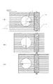
図1における各構成要素について説明する。印加部材1は、その先端部の回転軸中心からオフセットした位置に突起2を有する。さらに、印加部材1は回転軸中心に回転可能に保持する回転軸受け3によって支持され、荷重を付与する駆動手段であるコイルばね4によってシート材に予め定めた荷重を印加している。尚、不図示としたが回転軸受け3はハウジングに固定され、シート材との距離を略一定に保持されている。さらに、コイルばね4は両端を回転軸受け3と印加部材1に回転を阻害しないように固定された状態で圧縮され、印加部材1に荷重分の力を付与している。さらに、印加部材1には検知部5を接続した。さらに、印加部材1とシート材Pを挟んで対向する位置に、シート材に印加された荷重を受け止める受け材7が設けられ、さらにこの受け材7には必要に応じて感圧素子6を組み込む。この感圧素子6は第二の検知部として機能する。さらにこれらは緩衝材8を介して台座9に固定され、台座9にはシート材Pを支持する支持部10が設けられる。さらに、接触状態でのシート材と印加部材の相対位置を動かす搬送部11を設ける。また、必要に応じて印加部材1のシート材Pへの接触/非接触コントロールする手段を設ける。
Each component in FIG. 1 will be described. The application member 1 has a protrusion 2 at a position offset from the center of the rotation axis at the tip. Further, the applying member 1 is supported by a rotating bearing 3 that is rotatably held at the center of the rotating shaft, and applies a predetermined load to the sheet material by a coil spring 4 that is a driving means for applying a load. Although not shown, the rotary bearing 3 is fixed to the housing, and the distance from the sheet material is held substantially constant. Furthermore, the coil spring 4 is compressed in a state in which both ends are fixed to the rotary bearing 3 and the application member 1 so as not to inhibit the rotation, and a force corresponding to a load is applied to the application member 1. Furthermore, the
本実施例のシート材情報検知装置の動作概要を説明する。図2にこの動作過程での、印加部材、突起、シート材の移動の様子を模式的に示す。図2では、搬送が進むに従い、工程1、工程2、工程3と連続的に進行する。突起2は、印加部材1の中心軸(図中の一点鎖線で表記)に対して予め定めたオフセットをもって配される。まず工程1において、印加部材の初期位置が決定され、搬送が開始される。初期位置は、印加部材の中心軸と突起2の中心を結ぶ線が、シート材の搬送方向に対して所定のずれ角度を有する状態とすることで、スムーズな動作開始が可能となる。さらにシート材に接触した突起2が搬送力により連動して印加部材に回転方向(図では時計回り方向)の動作が生じる。その過程において接触した突起2にシート材の情報が伝播し、図の矢印方向で示すように、工程1ではシート材の短辺に略並行方向をスキャンしたシート材情報が得られる。さらに工程2に進むにつれて、突起2の移動とシート材Pとの相対的な角度が変化し、工程2においてはシート材の長辺に略並行方向をスキャンしたシート材情報が得られる。さらに工程3に進行し、工程3ではシート材の短辺に略並行方向をスキャンしたシート材情報が得られる。最後に必要に応じて前記初期位置に戻すか、シート材Pと印加部材1を離間させて終了する。 An outline of the operation of the sheet material information detection apparatus according to this embodiment will be described. FIG. 2 schematically shows the movement of the application member, the protrusion, and the sheet material in this operation process. In FIG. 2, the process proceeds continuously with process 1, process 2, and process 3 as the conveyance proceeds. The protrusion 2 is arranged with a predetermined offset with respect to the central axis of the application member 1 (indicated by a one-dot chain line in the drawing). First, in step 1, the initial position of the application member is determined, and conveyance is started. The initial position is such that the line connecting the central axis of the application member and the center of the protrusion 2 has a predetermined deviation angle with respect to the sheet material conveyance direction, so that a smooth operation can be started. Further, the protrusion 2 in contact with the sheet material is interlocked by the conveying force to cause the application member to move in the rotational direction (clockwise direction in the figure). In the process, information on the sheet material is propagated to the protrusions 2 that are in contact with each other, and as shown by the arrow direction in the figure, in step 1, sheet material information obtained by scanning the short side of the sheet material in a substantially parallel direction is obtained. Further, as the process proceeds to step 2, the relative angle between the movement of the protrusion 2 and the sheet material P changes. In step 2, sheet material information obtained by scanning the long side of the sheet material in a substantially parallel direction is obtained. Furthermore, it progresses to the process 3, In the process 3, the sheet material information which scanned the substantially parallel direction to the short side of the sheet material is obtained. Finally, the sheet is returned to the initial position as necessary, or the sheet material P and the application member 1 are separated from each other.
以下、本実施例のシート材情報検知装置の構成について詳細を説明する。 Hereinafter, the configuration of the sheet material information detection apparatus according to the present embodiment will be described in detail.
まず、印加部材について説明する。印加部材1は、先端部(シート材Pに接触する側)と軸部を有し、全体をZ軸を中心軸とする円柱形として、ステンレス材で一体構成した。先端部のシート材P側の先端面は半径20mmの球面加工を施した。印加部材1の全体の質量は4gとした。また、印加部材1は、その軸部を、軸方向に直線運動が可能で、かつ回転運動が可能なように保持する回転軸受け3にて支持される。回転軸受け3は摩擦による抵抗の少ない樹脂材料より構成し、本実施例ではフッ素系樹脂を用いた樹脂軸受けとした。印加部材1の回転軸中心は、シート材面と直交する方向(Z方向)とおおむね一致させた。 First, the application member will be described. The application member 1 has a front end portion (side in contact with the sheet material P) and a shaft portion, and the whole is integrally formed of a stainless material as a columnar shape having the Z axis as a central axis. The tip surface on the sheet material P side of the tip was subjected to spherical processing with a radius of 20 mm. The total mass of the application member 1 was 4 g. Further, the application member 1 is supported by a rotary bearing 3 that holds the shaft portion so as to be capable of linear motion in the axial direction and rotational motion. The rotary bearing 3 is made of a resin material having a low resistance due to friction. In this embodiment, the rotary bearing 3 is a resin bearing using a fluorine-based resin. The rotation axis center of the application member 1 was generally matched with the direction (Z direction) orthogonal to the sheet material surface.
印加部材1の先端部には突起2が設けられる。突起2は前記印加部材の先端面に一体として設けられる。突起2は印加部材と同じ材料で、半径2mmの球面状の突起とした。また、突起2の表面には、検知対象となるシート材の表面凹凸と相互作用しやすいように、シート材と同程度のRaを有するように加工を施した。また、突起2は、印加部材1の中心軸(図中の一点鎖線で表記)に対して予め定めたオフセットをもって配される。本実施例ではオフセット量は8mmとした。 A protrusion 2 is provided at the tip of the application member 1. The protrusion 2 is integrally provided on the tip surface of the application member. The protrusion 2 was made of the same material as the application member and was a spherical protrusion having a radius of 2 mm. Further, the surface of the protrusion 2 was processed so as to have the same Ra as that of the sheet material so as to easily interact with the surface unevenness of the sheet material to be detected. Further, the protrusion 2 is arranged with a predetermined offset with respect to the central axis of the application member 1 (indicated by a one-dot chain line in the drawing). In this embodiment, the offset amount is 8 mm.
印加部材1を駆動する駆動部は、本実施例ではコイルばね4により構成した。コイルばね4は所定の圧縮により、20gfの荷重をシート材Pに付与する。尚、この荷重値は静止状態の値であり、シート材との相互作用で変動する。またこのコイルばね4は、両端を回転軸受け3と印加手段1に固定しており、印加部材1の回転に対応してトーションばねとしてはたらき、適度な抵抗となる構成とした。 The drive part which drives the application member 1 was comprised by the coil spring 4 in the present Example. The coil spring 4 applies a load of 20 gf to the sheet material P by a predetermined compression. Note that this load value is a value in a stationary state, and varies depending on the interaction with the sheet material. Further, both ends of the coil spring 4 are fixed to the rotary bearing 3 and the applying means 1, and the coil spring 4 functions as a torsion spring corresponding to the rotation of the applying member 1 and has an appropriate resistance.
次に、検知部について説明する。検知部5は、印加部材1のシート材に接触する方と逆側に接合される。検知部5はチタン酸ジルコン酸鉛(PZT)セラミックスからなる圧電素子を振動板に接合したものである。
Next, the detection unit will be described. The
さらに、印加部材1とシート材Pを挟んで対向する位置に、シート材に印加された荷重を受け止める受け材7が設けられ、さらにこの受け材7には必要に応じて感圧素子6を組み込む。受け材7はステンレス材で構成し、感圧素子6は検知部5と同様のものを用いた。尚、感圧素子6の特性の、特に周波数特性を検知部と変えておくことで、シート材の異なる特性を検知することもできる。さらにこれらは緩衝材8を介して台座9に固定され、台座9にはシート材Pを支持する支持部10が設けられる。
Further, a receiving material 7 for receiving a load applied to the sheet material is provided at a position facing the application member 1 with the sheet material P interposed therebetween, and a pressure sensitive element 6 is incorporated in the receiving material 7 as necessary. . The receiving material 7 is made of stainless steel, and the pressure sensitive element 6 is the same as the detecting
さらに、支持部材8の支持部10の面と、受け材7の面には所定の段差構造を設けることもできる。前記段差構造により、シート材はその段差分撓んで運動する。これにより、出力信号にシート材特性のひとつである撓み剛性が反映される。すなわち、例えば、印加部材1にはシート材Pの撓み方向の振動による運動が伝播するが、その運動から、シート材の撓み剛性等の機械特性の差も検知できるものである。
Furthermore, a predetermined step structure can be provided on the surface of the
搬送部11は、接触状態でのシート材と印加部材の相対位置を動かすもので、本実施例ではシート材側を動かす機構を設けた。本実施例では一対のゴムローラーによりシート材を挟み、不図示のモーターから動力を供給して所定の搬送方向に搬送した。もちろん、これは本発明のシート材処理装置のシート材搬送機構を用いてもかまわない。 The conveyance unit 11 moves the relative position of the sheet material and the application member in the contact state, and in this embodiment, a mechanism for moving the sheet material side is provided. In this embodiment, the sheet material is sandwiched between a pair of rubber rollers, and power is supplied from a motor (not shown) to be conveyed in a predetermined conveyance direction. Of course, this may use the sheet material conveyance mechanism of the sheet material processing apparatus of the present invention.
また、必要に応じて印加部材1のシート材Pへの接触/非接触コントロールする手段を設ける。図4に、その例を示す。好ましくは、印加部材とシート材の離間、接触状態、さらにはシート材に撓みや圧縮の変位を加える範囲までをコントロールできると良い。また、印加部材に所定の速度を与えてシート材に当てても良い。シート材との接触時間をコントロールすることも好ましい。以上すべては、例えば図4に示したモーター12とカム13で印加部材とシート材面との距離を変える手段により容易に実現できる。
Further, a means for controlling contact / non-contact of the application member 1 to the sheet material P is provided as necessary. An example is shown in FIG. Preferably, it is possible to control the separation between the application member and the sheet material, the contact state, and the range in which the sheet material is subjected to bending or compression displacement. Alternatively, the applying member may be applied to the sheet material at a predetermined speed. It is also preferable to control the contact time with the sheet material. All of the above can be easily realized by, for example, means for changing the distance between the application member and the sheet material surface by the motor 12 and the
このような本実施例の装置で得られた出力信号から、必要に応じた解析処理によりシート材情報を取得する。解析処理としては、出力値のピークや半価幅や積算値の算出、出力波形の周波数成分解析等である。本実施例では、このような解析は複数種類組み合わせて行い、シート材の複数の情報を分離算出することも好ましい。 Sheet material information is acquired from the output signal obtained by the apparatus of this embodiment by analysis processing as necessary. The analysis processing includes calculation of an output value peak, a half-value width, an integrated value, an output waveform frequency component analysis, and the like. In the present embodiment, it is also preferable that such analysis is performed by combining a plurality of types, and a plurality of pieces of information on the sheet material are separately calculated.
以上述べてきたように、本実施例のシート材情報検知装置は、シート材に荷重を印加しながら接触する印加部材が、搬送によりシート材から回転力を受け、それに伴って突起とシート材が荷重を加えながら擦れあう際の印加部材の運動から情報を検知するものである。 As described above, in the sheet material information detection apparatus of the present embodiment, the application member that contacts while applying a load to the sheet material receives a rotational force from the sheet material by conveyance, and accordingly the protrusion and the sheet material are Information is detected from the movement of the application member when rubbing against each other while applying a load.
本実施例に拠れば、シート材処理装置の最適な制御のため、少なくとも機械特性と表面凹凸の特性情報とその異方性を含むシート材情報を取得することのできるシート材情報検知装置を提供することができる。 According to the present embodiment, for optimal control of the sheet material processing apparatus, a sheet material information detection apparatus capable of acquiring at least mechanical characteristics, surface unevenness characteristic information and sheet material information including its anisotropy is provided. can do.
実施例2として、本発明のシート材情報検知装置の他の例を示す。本実施例は、印加部材の回転運動を光学的な計測手段で計測する例である。 As Example 2, another example of the sheet material information detection apparatus of the present invention is shown. In this embodiment, the rotational movement of the application member is measured by an optical measuring means.
図3に本実施例の構成を示す。本実施例では、検知部5として、光学的に対象の動きを計測する機構を用いた。これは、対象に照射した光とその反射から、水平方向または上下方向の運動速度を割り出すもので、所謂レーザー変位計である。また、印加部材1には、その計測の補助のため、マーカーを設けている。これら機構を用いて、本実施例では印加部材1の所定時間の回転角を計測している。また、同時に、印加部材1の上下方向の運動(振動含む)を計測している。これ以外の基本構成は実施例1と同様である。
FIG. 3 shows the configuration of this embodiment. In this embodiment, a mechanism that optically measures the movement of the object is used as the
本実施例のシート材情報検知装置の動作の概要を説明する。検知される印加部材の回転角は、シート材との相互作用力を以って決まる。すなわちシート材Pと突起2との間の相互作用力が大きい場合はスリップ無く回転するので回転角は大きくなる。逆に相互作用力が小さい場合は回転角は小さくなる。この相互作用力はシート材の表面状態に関わる特性(凹凸、摩擦係数、水分等の吸着成分、など)を反映するので、回転回転角からシート材情報の検知が可能となる。また、シート材の機械特性の検知は、検知部が変わっても実施例1と同様に印加部材の運動検知が可能であることで、検知できる。 An outline of the operation of the sheet material information detection apparatus of the present embodiment will be described. The detected rotation angle of the application member is determined by the interaction force with the sheet material. That is, when the interaction force between the sheet material P and the protrusion 2 is large, the rotation angle increases because the sheet material P rotates without slipping. Conversely, when the interaction force is small, the rotation angle is small. Since this interaction force reflects characteristics related to the surface state of the sheet material (unevenness, friction coefficient, adsorption component such as moisture, etc.), the sheet material information can be detected from the rotational rotation angle. Further, the mechanical characteristics of the sheet material can be detected by detecting the motion of the application member in the same manner as in the first embodiment even if the detection unit is changed.
以上本実施例に拠れば、シート材処理装置の最適な制御のため、少なくとも機械特性と表面凹凸の特性情報とその異方性を含むシート材情報を取得することのできるシート材情報検知装置を提供することができる。 As described above, according to the present embodiment, for optimal control of the sheet material processing apparatus, there is provided a sheet material information detection apparatus capable of acquiring sheet material information including at least mechanical characteristics, surface unevenness characteristic information and anisotropy thereof. Can be provided.
特に、シート材の表面状態に関わる、凹凸、摩擦係数、水分等の吸着成分、などの情報を効果的に検知できる。 In particular, it is possible to effectively detect information related to the surface state of the sheet material, such as unevenness, friction coefficient, and adsorbing components such as moisture.
実施例3として、本発明のシート材処理装置の例について説明する。図5に、本実施例のシート材処理装置の動作フローを示す。 As Example 3, an example of the sheet material processing apparatus of the present invention will be described. FIG. 5 shows an operation flow of the sheet material processing apparatus of this embodiment.
まず、シート材処理動作をスタートし、シート材の搬送を開始する。シート材処理動作のスタートは、シート材処理装置のユーザー(オペレーター)が、機械本体のスタートボタンを押す、あるいは接続された外部コンピュータやカメラなどの周辺機器から処理命令を送るなどして開始される。 First, the sheet material processing operation is started, and conveyance of the sheet material is started. The sheet material processing operation starts when the user (operator) of the sheet material processing apparatus presses a start button on the machine body or sends a processing command from a connected peripheral device such as an external computer or camera. .
続いて、シート材情報検知装置の動作がスタートする。該スタートは、本実施例のシート材情報検知装置を搭載するシート材処理装置において、シート材処理の動作が開始したことを受けて行われる。 Subsequently, the operation of the sheet material information detection apparatus starts. The start is performed in response to the start of the sheet material processing operation in the sheet material processing apparatus equipped with the sheet material information detection apparatus of the present embodiment.
続いて、シート材情報検知装置の制御回路に、シート材搬送情報が入力される。該シート材搬送情報とは、シート材の位置や速度に関する情報である。すなわち、該搬送情報とは、シート材がシート材情報検知装置の位置を通過するタイミングを意味する。該搬送情報に対応してシート材情報検知装置の駆動(荷重印加等)のタイミングが決定される。前記シート材搬送情報は、例えばシート材処理装置のシート材通過センサの信号や、シート材処理装置の動作開始などの情報を処理したものである。 Subsequently, sheet material conveyance information is input to the control circuit of the sheet material information detection apparatus. The sheet material conveyance information is information relating to the position and speed of the sheet material. That is, the conveyance information means the timing at which the sheet material passes the position of the sheet material information detection device. Corresponding to the conveyance information, the timing of driving (load application or the like) of the sheet material information detection apparatus is determined. The sheet material conveyance information is obtained by processing information such as a signal from a sheet material passage sensor of the sheet material processing apparatus and an operation start of the sheet material processing apparatus.
続いて、前記シート材搬送情報を受けて、シート材情報検知の動作を開始する。 Subsequently, upon receiving the sheet material conveyance information, the operation of detecting the sheet material information is started.
シート材情報検知動作開始後、検知部からの出力が適正か否かで、以下のフローは異なる。 After the sheet material information detection operation starts, the following flow differs depending on whether or not the output from the detection unit is appropriate.
出力が適正でなかった場合(NO)について説明する。出力が適正でない場合とは、例えば動作開始後所定の時間内に一定レベル範囲の出力が無い場合などである。この場合、後過程の中止、もしくは得られた情報のキャンセルを行う。さらに、シート材情報検知装置が異常であるという異常情報出力を行う。 A case where the output is not appropriate (NO) will be described. The case where the output is not appropriate is, for example, the case where there is no output in a certain level range within a predetermined time after the operation starts. In this case, the subsequent process is canceled or the obtained information is canceled. Furthermore, the abnormality information output that the sheet material information detection apparatus is abnormal is performed.
異状が軽微と判断される場合は、必ずしもシート材処理を中止する必要は無く、例えばシート材情報検知装置の動作を停止した上で、デフォルト条件にてシート材処理を行ってもよい。異状が軽微であるという判断は、例えばシート材の搬送が正常に行われていることが確認できた場合や、繰り返しのシート材処理において低確率で突発的に異常が発生した場合などである。しかし、該異常が及ぼす影響が甚大と考えられる場合は、シート材処理を中止する。シート材処理の中止は、搬送停止または排紙し、シート材処理装置の異常表示や適宜復帰指示を行う。また、必要に応じて次のシート材処理への影響を判断し、適切な処理を行う。以上の処理をもって動作終了する。 When it is determined that the abnormality is minor, it is not always necessary to stop the sheet material processing. For example, the sheet material processing may be performed under default conditions after the operation of the sheet material information detection apparatus is stopped. The judgment that the abnormality is minor is, for example, when it is confirmed that the sheet material is normally conveyed, or when an abnormality occurs suddenly with low probability in repeated sheet material processing. However, if the influence of the abnormality is considered to be enormous, the sheet material processing is stopped. To stop the sheet material processing, the conveyance is stopped or the paper is discharged, and an abnormality display of the sheet material processing apparatus or an appropriate return instruction is performed. Further, the influence on the next sheet material processing is determined as necessary, and appropriate processing is performed. The operation ends with the above processing.
次に、出力が適正であった場合(YES)について説明する。本発明のシート材情報検知装置により、シート材情報の検知を行う。続いて、該シート材情報に基づき、シート材処理条件が決定される。続いて、決定されたシート材処理条件に基づき、画像形成などのシート材処理が行われる。本実施例のシート材処理装置においては、シート材情報に基づいて処理プロセスが決定され、処理の各工程において必要な制御が行われる。本実施例のシート材処理装置で、特に重要な制御は、シート材の搬送に関わる制御である。例えば、剛度の高いシート材に対しては搬送ローラーの荷重の値を大きくする。また、シート材の機械特性の速度依存性を考慮し適切な荷重印加速度を決定するものである。以上の処理をもって動作終了する。 Next, a case where the output is appropriate (YES) will be described. The sheet material information is detected by the sheet material information detection apparatus of the present invention. Subsequently, a sheet material processing condition is determined based on the sheet material information. Subsequently, sheet material processing such as image formation is performed based on the determined sheet material processing conditions. In the sheet material processing apparatus of the present embodiment, a processing process is determined based on the sheet material information, and necessary control is performed in each process step. In the sheet material processing apparatus of the present embodiment, particularly important control is control related to conveyance of the sheet material. For example, the load value of the transport roller is increased for a sheet material having high rigidity. In addition, an appropriate load application speed is determined in consideration of the speed dependency of the mechanical properties of the sheet material. The operation ends with the above processing.
以上、本実施例のシート材処理装置によれば、シート材面に直行する方向を含む複数の方向の情報を含む、シート材情報に基づいて、最適な工程制御が可能なシート材処理装置を提供することができる。 As described above, according to the sheet material processing apparatus of the present embodiment, the sheet material processing apparatus capable of optimal process control based on the sheet material information including information on a plurality of directions including the direction orthogonal to the sheet material surface. Can be provided.
1 印加部材
2 突起
3 回転軸受け
4 駆動部(コイルばね)
5 検知部
6 感圧素子
7 受け材
8 緩衝材
9 台座
10 支持部
11 搬送部
12 モーター
13 カム
DESCRIPTION OF SYMBOLS 1 Application member 2 Protrusion 3 Rotating bearing 4 Drive part (coil spring)
DESCRIPTION OF
Claims (2)
該印加部材を少なくとも一つの回転軸中心に回転可能に保持する回転軸受け部と、
前記印加部材のシート材に接触する部分の回転軸より予め定めたオフセットを有する位置に設けた突起と、
接触状態での前記シート材と前記印加部材との相対位置を変化させる搬送部と、
前記印加部材の運動を検知する検知部と、
を有し、
検知部の情報に基づいてシート材の特性を検知することを特徴とするシート材情報検知装置。 A sheet material information detection device that detects and outputs information on a sheet material, an application member that applies a load in contact with the sheet material,
A rotary bearing portion that rotatably holds the application member at the center of at least one rotary shaft;
A protrusion provided at a position having a predetermined offset from the rotation axis of the portion of the application member that contacts the sheet material;
A transport unit that changes a relative position between the sheet member and the application member in a contact state;
A detection unit for detecting movement of the application member;
Have
A sheet material information detection apparatus that detects characteristics of a sheet material based on information of a detection unit.
Priority Applications (2)
| Application Number | Priority Date | Filing Date | Title |
|---|---|---|---|
| JP2006343053A JP2008156004A (en) | 2006-12-20 | 2006-12-20 | Sheet material information detecting means and sheet material handling device |
| US11/951,854 US7634943B2 (en) | 2006-12-20 | 2007-12-06 | Sheet material information acquiring device and sheet material processing apparatus including same |
Applications Claiming Priority (1)
| Application Number | Priority Date | Filing Date | Title |
|---|---|---|---|
| JP2006343053A JP2008156004A (en) | 2006-12-20 | 2006-12-20 | Sheet material information detecting means and sheet material handling device |
Publications (2)
| Publication Number | Publication Date |
|---|---|
| JP2008156004A true JP2008156004A (en) | 2008-07-10 |
| JP2008156004A5 JP2008156004A5 (en) | 2010-01-21 |
Family
ID=39541718
Family Applications (1)
| Application Number | Title | Priority Date | Filing Date |
|---|---|---|---|
| JP2006343053A Withdrawn JP2008156004A (en) | 2006-12-20 | 2006-12-20 | Sheet material information detecting means and sheet material handling device |
Country Status (2)
| Country | Link |
|---|---|
| US (1) | US7634943B2 (en) |
| JP (1) | JP2008156004A (en) |
Cited By (2)
| Publication number | Priority date | Publication date | Assignee | Title |
|---|---|---|---|---|
| CN111538219A (en) * | 2019-02-07 | 2020-08-14 | 柯尼卡美能达株式会社 | Measuring device, image forming apparatus, and measuring method |
| KR20210067364A (en) * | 2019-11-29 | 2021-06-08 | 포항공과대학교 산학협력단 | Object identification apparatus and method, system comprising the same |
Families Citing this family (3)
| Publication number | Priority date | Publication date | Assignee | Title |
|---|---|---|---|---|
| US20150345996A1 (en) * | 2014-05-29 | 2015-12-03 | Corning Incorporated | Apparatuses and methods for measuring an angle between a web of material and a conveyance direction |
| US20150344347A1 (en) * | 2014-05-29 | 2015-12-03 | Corning Incorporated | Apparatuses for steering flexible glass webs and methods for using the same |
| JP6828315B2 (en) * | 2016-08-31 | 2021-02-10 | セイコーエプソン株式会社 | Recording device |
Family Cites Families (15)
| Publication number | Priority date | Publication date | Assignee | Title |
|---|---|---|---|---|
| US4135393A (en) * | 1978-02-14 | 1979-01-23 | Jordan Donald J | Tensiometer |
| US4201093A (en) * | 1978-07-20 | 1980-05-06 | Metriguard, Inc. | Ultrasonic sheet material testing apparatus |
| US5934140A (en) | 1996-06-19 | 1999-08-10 | Xerox Corporation | Paper property sensing system |
| US6097497A (en) * | 1998-02-19 | 2000-08-01 | Compaq Computer Corporation | System and method for automating print medium selection and for optimizing print quality in a printer |
| US7334342B1 (en) * | 1998-02-27 | 2008-02-26 | William Ack Barr | Marking device having marking members |
| JP2002068528A (en) | 2000-08-29 | 2002-03-08 | Sharp Corp | Recording medium detecting device and image forming device using the same |
| JP4143602B2 (en) * | 2002-06-04 | 2008-09-03 | キヤノン株式会社 | Double feed detection method, double feed detection apparatus, image forming apparatus, and image reading apparatus |
| JP4110090B2 (en) * | 2002-12-26 | 2008-07-02 | キヤノン電子株式会社 | Information detection apparatus, image forming apparatus including the information detection apparatus, and information acquisition method |
| JP3658392B2 (en) * | 2002-12-27 | 2005-06-08 | キヤノン電子株式会社 | Signal output device and sheet material processing apparatus provided with signal output device |
| JP4514471B2 (en) * | 2003-02-20 | 2010-07-28 | キヤノン電子株式会社 | Sheet material information detection apparatus, skew correction unit, and sheet material processing apparatus |
| JP4684939B2 (en) * | 2005-06-03 | 2011-05-18 | キヤノン株式会社 | Sheet material identification device and image forming apparatus |
| JP4378330B2 (en) * | 2005-08-15 | 2009-12-02 | キヤノン株式会社 | Sheet information output apparatus, sheet processing apparatus, and image forming apparatus |
| JP4684958B2 (en) * | 2006-06-28 | 2011-05-18 | キヤノン株式会社 | Sheet material information detection apparatus and sheet material processing apparatus |
| JP4709080B2 (en) * | 2006-06-28 | 2011-06-22 | キヤノン株式会社 | Sheet material information detection apparatus, sheet material processing apparatus, and sheet material processing method |
| JP2008150145A (en) * | 2006-12-15 | 2008-07-03 | Canon Inc | Sheet material information detecting means and sheet material handling device |
-
2006
- 2006-12-20 JP JP2006343053A patent/JP2008156004A/en not_active Withdrawn
-
2007
- 2007-12-06 US US11/951,854 patent/US7634943B2/en not_active Expired - Fee Related
Cited By (3)
| Publication number | Priority date | Publication date | Assignee | Title |
|---|---|---|---|---|
| CN111538219A (en) * | 2019-02-07 | 2020-08-14 | 柯尼卡美能达株式会社 | Measuring device, image forming apparatus, and measuring method |
| KR20210067364A (en) * | 2019-11-29 | 2021-06-08 | 포항공과대학교 산학협력단 | Object identification apparatus and method, system comprising the same |
| KR102272641B1 (en) * | 2019-11-29 | 2021-07-02 | 포항공과대학교 산학협력단 | Object identification apparatus and method, system comprising the same |
Also Published As
| Publication number | Publication date |
|---|---|
| US20080150226A1 (en) | 2008-06-26 |
| US7634943B2 (en) | 2009-12-22 |
Similar Documents
| Publication | Publication Date | Title |
|---|---|---|
| JP4709080B2 (en) | Sheet material information detection apparatus, sheet material processing apparatus, and sheet material processing method | |
| JP2008150145A (en) | Sheet material information detecting means and sheet material handling device | |
| JP4378330B2 (en) | Sheet information output apparatus, sheet processing apparatus, and image forming apparatus | |
| JP4684958B2 (en) | Sheet material information detection apparatus and sheet material processing apparatus | |
| JP4110090B2 (en) | Information detection apparatus, image forming apparatus including the information detection apparatus, and information acquisition method | |
| JP4684939B2 (en) | Sheet material identification device and image forming apparatus | |
| JP4514471B2 (en) | Sheet material information detection apparatus, skew correction unit, and sheet material processing apparatus | |
| JP3658392B2 (en) | Signal output device and sheet material processing apparatus provided with signal output device | |
| JP2006206321A (en) | Signal output device, sheet material identification device, image forming device with the same, and sheet material identification method | |
| JP2008156004A (en) | Sheet material information detecting means and sheet material handling device | |
| JP2012197178A (en) | Sheet feeding device and image forming apparatus | |
| JP4785427B2 (en) | Identification device | |
| JP2004161444A (en) | Sheet material discriminating device | |
| JP4684955B2 (en) | Sheet material information detection apparatus and sheet material processing apparatus | |
| JP4143417B2 (en) | Sheet material discriminating method, sheet material discriminating apparatus, and image forming apparatus | |
| JP2008151592A (en) | Sheet material information detection device and sheet material treatment device | |
| JP2006337336A (en) | Sheet material information output device | |
| JP4262052B2 (en) | Sheet material information detection apparatus and sheet material processing apparatus including the sheet material information detection apparatus | |
| JP4994978B2 (en) | Sheet material identification apparatus, image forming apparatus, and surface property identification apparatus | |
| JP2006306578A (en) | Device and method for outputting signal on sheet, and image forming device | |
| JP2005351676A (en) | Sheet material information detector and sheet material processor | |
| JP2006184087A (en) | Signal output device on sheet material |
Legal Events
| Date | Code | Title | Description |
|---|---|---|---|
| A521 | Request for written amendment filed |
Free format text: JAPANESE INTERMEDIATE CODE: A523 Effective date: 20091127 |
|
| A621 | Written request for application examination |
Free format text: JAPANESE INTERMEDIATE CODE: A621 Effective date: 20091127 |
|
| RD04 | Notification of resignation of power of attorney |
Free format text: JAPANESE INTERMEDIATE CODE: A7424 Effective date: 20100201 |
|
| RD01 | Notification of change of attorney |
Free format text: JAPANESE INTERMEDIATE CODE: A7421 Effective date: 20100630 |
|
| A761 | Written withdrawal of application |
Free format text: JAPANESE INTERMEDIATE CODE: A761 Effective date: 20110620 |