JP2008140413A - Storage device system - Google Patents
Storage device system Download PDFInfo
- Publication number
- JP2008140413A JP2008140413A JP2008002274A JP2008002274A JP2008140413A JP 2008140413 A JP2008140413 A JP 2008140413A JP 2008002274 A JP2008002274 A JP 2008002274A JP 2008002274 A JP2008002274 A JP 2008002274A JP 2008140413 A JP2008140413 A JP 2008140413A
- Authority
- JP
- Japan
- Prior art keywords
- storage
- interface control
- interface
- storage device
- information
- Prior art date
- Legal status (The legal status is an assumption and is not a legal conclusion. Google has not performed a legal analysis and makes no representation as to the accuracy of the status listed.)
- Pending
Links
Images


Landscapes
- Information Retrieval, Db Structures And Fs Structures Therefor (AREA)
Abstract
Description
本発明は、計算機システムで用いられる記憶装置システムに関する。 The present invention relates to a storage device system used in a computer system.
記憶装置システムと計算機とを接続するためのインターフェースは、大きく分けて二つのタイプが存在する。第一は、記憶装置システムにおけるデータの管理単位であるブロックを単位として、記憶装置システムと計算機との間の入出力(以下「I/O」)が行われる「ブロックI/Oインタフェース」である。ブロックI/Oインタフェースには、ファイバチャネル(Fibre Channel)、SCSI(Small Computer Systems Interface)などの種類がある。 There are roughly two types of interfaces for connecting the storage system and the computer. The first is a “block I / O interface” in which input / output (hereinafter “I / O”) is performed between a storage device system and a computer in units of blocks, which are data management units in the storage device system. . There are various types of block I / O interfaces, such as Fiber Channel and SCSI (Small Computer Systems Interface).
ブロックI/Oインタフェースを有する複数の記憶装置システム及び複数の計算機が相互に接続されたネットワークは、ストレージエリアネットワーク(SAN)と称される。SANは、ファイバチャネルを用いて構築されることが多い。尚、ファイバチャネルを用いたSANに接続される記憶装置システムの一例が、特開平10−333839号公報に開示されている。 A network in which a plurality of storage device systems having a block I / O interface and a plurality of computers are connected to each other is referred to as a storage area network (SAN). SANs are often built using Fiber Channel. An example of a storage system connected to a SAN using a fiber channel is disclosed in Japanese Patent Laid-Open No. 10-333839.
第二は、計算機で実行されるアプリケーションプログラムが認識するファイル単位で、記憶装置システムと計算機との間のI/Oが行われる「ファイルI/Oインタフェース」である。ファイルI/Oインタフェースでは、従来のファイルサーバで使用されているネットワークファイルシステムのプロトコルが用いられることが多い。特に、ファイルサーバの機能のうち、記憶装置システムに特化した機能と記憶装置システムとを組み合わせた装置は、ネットワークアタッチドストレージ(NAS)と称される。NASは、ローカルエリアネットワーク(LAN)等に直接接続される。 The second is a “file I / O interface” in which I / O is performed between the storage system and the computer in units of files recognized by an application program executed on the computer. The file I / O interface often uses a network file system protocol used in a conventional file server. In particular, among the functions of the file server, a device that combines a storage device system and a function specialized for the storage device system is called network attached storage (NAS). The NAS is directly connected to a local area network (LAN) or the like.
SANでは、計算機間のメッセージ交換用のネットワークとは別に設けられた記憶装置システム専用の高速ネットワークで、計算機と記憶装置システムとが接続される。このため、SANでは、計算機とLANで接続されるNASに比べて高速なデータの授受が可能である。また、SANではブロックI/Oインタフェースが採用されているので、NASに比べてプロトコル処理のオーバヘッドが小さく、高速なレスポンスを得ることができる。 In the SAN, a computer and a storage device system are connected by a high-speed network dedicated to a storage device system provided separately from a network for exchanging messages between computers. Therefore, in SAN, data can be exchanged at a higher speed than NAS connected to a computer via LAN. Further, since the block I / O interface is adopted in the SAN, the overhead of the protocol processing is small compared with the NAS, and a high-speed response can be obtained.
この反面、SANは、記憶装置システム専用のネットワークが必要となるので、ユーザにおいては、SANを導入する際のコストが大きい。したがって、SANは、主に企業の基幹システムで使用されており、データベースの構築を目的として利用されることが多い。 On the other hand, since the SAN requires a network dedicated to the storage device system, the cost for introducing the SAN is high for the user. Therefore, the SAN is mainly used in a company's backbone system and is often used for the purpose of constructing a database.
一方、NASは既存のLANをそのまま使用できるので、導入の際のコストが小さく、導入が容易である。又、NASでは標準化されたネットワークファイルシステムが使用されるので、NASユーザは、一般的なファイルを単位としてデータを管理できる。このため、データの管理が容易で、かつ複数の計算機で容易にファイルを共有することができる。 On the other hand, since NAS can use an existing LAN as it is, the cost at the time of introduction is small and the introduction is easy. Also, since NAS uses a standardized network file system, NAS users can manage data in units of general files. Therefore, data management is easy, and files can be easily shared by a plurality of computers.
その反面、NASは、計算機間の通信にも使用されるLANを介して計算機とデータのやり取りを行う。したがって、LANの負荷が増大するおそれがある。また、ネットワークファイルシステムで用いられるプロトコルの処理のオーバヘッドが大きく、レスポンスの性能はSANより低速となる。このことから、NASは、企業のファイル管理システムに主に使用されており、Webコンテンツの管理や、CADのデータファイル管理等のアプリケーションに利用されることが多い。 On the other hand, the NAS exchanges data with a computer via a LAN that is also used for communication between computers. Therefore, the load on the LAN may increase. In addition, the overhead of processing a protocol used in the network file system is large, and the response performance is slower than that of the SAN. For this reason, NAS is mainly used in corporate file management systems, and is often used for applications such as Web content management and CAD data file management.
上述のように、NASとSANはお互いに補完しあう関係にあり、また、適用される分野も異なる。したがって、一般に、両方は、適所に使い分けられている。 As described above, NAS and SAN are complementary to each other, and applied fields are also different. Therefore, in general, both are properly used in place.
また、各計算機が、記憶装置システムが有する記憶容量を、必要な時に必要な分だけ利用できるように、記憶装置システム内の資源(以下「デバイス」)の設定、デバイスの各計算機への割り当てを容易に行えるようにする技術として、ストレージプールと呼ばれる技術がある。ストレージプールの一例は、特開2001−142648公報に開示されている。 Also, in order for each computer to use the storage capacity of the storage system as much as necessary, it is necessary to set resources (hereinafter “devices”) in the storage system and assign devices to each computer. There is a technique called a storage pool as a technique that can be easily performed. An example of a storage pool is disclosed in Japanese Patent Laid-Open No. 2001-142648.
従来技術でSANとNASとを含んだシステムを構築しようとした場合、SANの機能を有する記憶装置システムと、NASの両方が必要になる。この場合、構築されたシステムのユーザは、種類の異なる記憶装置システムを別個に管理する必要があり、システムを管理し運用するためのコストが増大してしまうという課題がある。 When an attempt is made to construct a system including a SAN and a NAS in the prior art, both a storage device system having a SAN function and a NAS are required. In this case, the user of the constructed system needs to separately manage different types of storage device systems, which increases the cost for managing and operating the system.
また、SANの機能を備える記憶装置システムと、NASの各々を有するシステムでは、システムのユーザは、各々の記憶装置システムごとに記憶容量を管理する必要がある。具体的には、ユーザは、1台1台異なる環境設定や記憶容量の管理を行わなくてはならない。したがって、システムのユーザにとって、記憶装置システムの管理が煩雑かつ困難なものになるという課題がある。 Further, in a storage device system having a SAN function and a system having each of NAS, the system user needs to manage the storage capacity for each storage device system. Specifically, the user must manage different environment settings and storage capacities. Therefore, there is a problem that the management of the storage device system becomes complicated and difficult for the user of the system.
さらに、SANとNASとを含んだシステムにおいて、SANに使用される記憶装置システムの記憶容量が不足したとき、たとえNASの記憶容量に余裕があったとしても、各々の記憶装置システムの管理体系が異なるので、ユーザは、NASに存在する記憶容量を自由に利用することはできない。つまり、ユーザは、システム全体が有する記憶容量を有効に利用できないという課題がある。 Further, in a system including SAN and NAS, when the storage capacity of the storage device system used for the SAN is insufficient, the management system of each storage device system is different even if the storage capacity of the NAS is sufficient. Since they are different, the user cannot freely use the storage capacity existing in the NAS. That is, there is a problem that the user cannot effectively use the storage capacity of the entire system.
本発明の目的は、複数種類の記憶装置システムにかかる管理運用コストを低減できる記憶装置システムを提供することである。 An object of the present invention is to provide a storage device system that can reduce the management operation cost for a plurality of types of storage device systems.
また、本発明のさらなる目的は、システム全体が有する記憶容量の管理を容易にするとともに、記憶容量の効率的な利用を実現する記憶装置システムを提供することである。 A further object of the present invention is to provide a storage device system that facilitates management of the storage capacity of the entire system and realizes efficient use of the storage capacity.
上記目的を達成するために、本発明の記憶装置システムは、複数種類のインターフェース制御装置が装填される複数のスロット、複数のディスク装置、及び前記複数のディスク装置が有する記憶領域を前記スロットに割り当てる手段とを有する構成とする。 In order to achieve the above object, a storage device system according to the present invention allocates a plurality of slots into which a plurality of types of interface control devices are loaded, a plurality of disk devices, and a storage area of the plurality of disk devices to the slots. Means.
また、複数種類のインターフェース制御装置には、SANの機能を備えるブロックI/Oインタフェース制御装置、NASの機能を備えるファイルI/Oインタフェース制御装置が含まれる構成が考えられる。 In addition, the plurality of types of interface control devices may include a block I / O interface control device having a SAN function and a file I / O interface control device having a NAS function.
さらに、本発明の好ましい実施態様として、各インターフェース制御装置は同一の形状を有する構成が考えられる。 Furthermore, as a preferred embodiment of the present invention, a configuration in which each interface control device has the same shape can be considered.
また、本発明の好ましい実施態様として、記憶装置システムは、あるインターフェース制御装置に割り当てた記憶領域を別の種類のインターフェース制御装置に割り当てる手段を有する構成が考えられる。 Further, as a preferred embodiment of the present invention, a configuration in which the storage device system has means for allocating a storage area allocated to a certain interface control device to another type of interface control device can be considered.
図1は、本発明を適用した記憶装置システムの実施形態を示した図である。記憶装置システム1は、LAN20及び21を介して、NASクライアント400と接続される。本実施形態では、LAN20及び21はIPネットワーク(以下単に「ネットワーク」と称する)である。また、記憶装置システム1は、SAN30を介して、SANクライアント500と接続される。本実施形態ではSAN30は、ファイバチャネルであるとする。
FIG. 1 is a diagram showing an embodiment of a storage system to which the present invention is applied. The
又、記憶装置システム1は、管理端末18と接続されている。管理端末18は、ユーザに対し各種情報を提示するためのディスプレイ、及びユーザからの情報の入力を受け付けるためのキーボード、マウスなどの入出力装置を備える。管理端末18は、通信ネットワーク19を介して記憶装置システム1と通信することができ、ユーザが、記憶装置システム1の各種設定を行うために用いられる。
The
このように、記憶装置システム1は、ファイバチャネルで構成され、ブロックI/Oインタフェースが用いられるSANと、IPネットワークで構成され、ファイルI/Oインタフェースが用いられるNASに適応するインターフェースの、両方のインターフェースを有する記憶装置システムである。尚、記憶装置システム1のインターフェースは、SAN対応とNAS対応の任意の組み合わせが可能である。特に、SANのみ又はNASのみに対応するインターフェースを有するシステムを構成することも可能である。
As described above, the
記憶装置システム1は、ディスクコントローラ(以下、「DKC」と称する)11及び記憶装置(以下「ディスク」と称する)1700を有する。DKC11は、ネットワークチャネルアダプタ(以下CHN)1100、ファイバチャネルアダプタ(以下CHF)1110、ディスクアダプタ1200(以下、DKA)、共有メモリ13(以下SM)、キャッシュメモリ14(以下CM)、及びディスクプール管理部15(以下DPM)を有する。
The
CHN1100は、ファイルI/OインタフェースでNASクライアント400と接続されるインターフェース制御部である。CHF1110は、ブロックI/OインタフェースでSANクライアント500と接続されるインターフェース制御部である。以下、CHN及びCHFをまとめてチャネルアダプタ(以下CH)と称する。
The CHN 1100 is an interface control unit connected to the NAS
DKA1200は、ディスク1700と接続されている。DKA1200は、接続されているディスク1700とクライアント間のデータ転送を制御する。SM13には、記憶装置システム1の構成を管理する構成管理情報や、CM14の制御情報等が格納される。SM13に格納されているデータは、全てのCHおよび全てのDKAに共有される。CM14には、ディスク1700のデータが一時的に保存(以下「キャッシュする」と称する)される。CM14のデータも、全てのCHおよび全てのDKA1200に共有される。記憶装置システム1では、すべてのCHが、CM14及びすべてのディスク1700へアクセスすることが出来る構成となっている。このような構成は、クロスバスイッチ等で実現できるディスクプール管理部15(以下DPM)は、全てのディスク1700を一括して管理する。具体的には、DPM15には、ディスク1700の記憶容量全てをまとめて一つのディスクプールとして扱うための情報が格納されている。尚、CH、DKA及びDPM15は、管理ネットワーク16によって各々接続される。又、DPM15は、通信ネットワーク19を介して、管理端末18と接続される。
The DKA1200 is connected to the
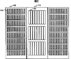
図2は、記憶装置システム1の外観を示す図である。DKC筐体115は、CHN1100、 CHF1110、DKA1200、SM13、及びCM14を格納する。ディスクユニット筐体(以下、「DKU」と称する)180は、ディスク1700を格納する。SM13は、実際には複数のコントローラボード1300で構成される。また、CM14も、複数のキャッシュボード1400で構成される。記憶装置システム1の使用者は、ボードやディスクの枚数を増減して、所望の記憶容量を得る。
FIG. 2 is a diagram illustrating an external appearance of the
DKC筐体115は、複数のインタフェースアダプタスロット190を有する。各々のインタフェースアダプタスロット190には、CHN1100等が搭載されたアダプタボードが格納される。本実施形態においては、インタフェースアダプタスロット190の形状、アダプタボードのサイズ及びコネクタの形状を、インターフェースの種類を問わず同一にし、各種インターフェースのアダプタの互換性を保つようにする。したがって、DKC筐体115が有するインタフェースアダプタスロット190には、インターフェースの種類を問わず、任意のアダプタボードを装填することができる。
The
また、記憶装置システム1の使用者は、CHN1100及びCHF1110のアダプタボードの数を自由に組み合わせて、記憶装置システム1のインタフェースアダプタスロット190に装填することが出来る。これにより、記憶装置システム1の使用者は、記憶装置システム1のインターフェースを自由に構成することができる。
Further, the user of the
図3は、CHN1100が作りこまれたアダプタボードの構成を示す図である。コネクタ11007は、DKC筐体115が有するコネクタと接続される。本実施形態においては、上述したように、CHN1100及びCHF1110は同一形状のコネクタを有する。インタフェースコネクタ2001は、LANに対応している。尚、アダプタボードがCHF1110の場合、インタフェースコネクタ2001は、ファイバチャネルに対応する。
FIG. 3 is a diagram showing a configuration of an adapter board in which the
図4は、CHN1100の内部構成を示す図である。CHN1100は、プロセッサ11001、LANコントローラ11002、管理ネットワークコントローラ11003、メモリ11004、SMI/F制御部11005及びCMI/F制御部11006を有する。
FIG. 4 is a diagram illustrating an internal configuration of the
プロセッサ11001は、CHN1100全体の制御を行う。LANコントローラ11002は、CHN1100とLANとの間の通信の制御を行う。管理ネットワークコントローラ11003は、CHN1100と管理ネットワーク16との間の通信の制御を行う。プロセッサ11001に接続されるメモリ11004には、プロセッサ11001が実行するプログラムや制御データが格納される。
The
SMI/F制御部11005は、CHN1100とSM13との間のデータ転送を制御する。CMI/F制御部11006は、CHN1100とCM14との間のデータ転送を制御する。
SMI /
メモリ11004には、オペレーティングシステムプログラム110040、LANコントローラドライバプログラム110041、TCP/IPプログラム110042、ファイルシステムプログラム110043、ネットワークファイルシステムプログラム110044、ディスクボリューム制御プログラム110045、キャッシュ制御プログラム110046、ディスクプール情報取得プログラム110048、及びディスクプール情報管理テーブル110049が格納される。又、メモリ11004は、データバッファ110047を有する。
The
オペレーティングシステムプログラム110040は、メモリ11004に格納されたプログラム全体の管理や入出力制御に用いられる。LANコントローラドライバプログラム110041は、LANコントローラ11002の制御に用いられる。TCP/IPプログラム110042は、LAN上の通信プロトコルであるTCP/IPの制御に用いられる。ファイルシステムプログラム110043は、ディスク1700に格納されるファイルの管理に用いられる。
The
ネットワークファイルシステムプログラム110044は、ディスク1700に格納されるファイルをNASクライアント400に提供するためのネットワークファイルシステムのプロトコル制御に用いられる。ディスクボリューム制御プログラム110045は、ディスク1700に設定されたディスクボリュームへのアクセスを制御するために用いられる。キャッシュ制御プログラム110046は、CM14に格納されるデータの管理や、CM14におけるデータのヒット/ミス判定等の制御に用いられる。
The network file system program 110044 is used for protocol control of the network file system for providing the
ディスクプール情報取得プログラム110048は、CHN1100が、SM13に格納されているディスクプールの情報を入手する際に実行される。ディスクプール情報管理テーブル110049には、入手されたディスクプール情報が格納される。データバッファ110047は、NASクライアント400とCM14との間のデータ転送速度の調整、及びファイルデータをキャッシュするために用いられる。
The disk pool
なお、プロセッサ11001は、単一のプロセッサや、複数のプロセッサの集合体の構成も考えられる。例えば、制御に伴う処理を水平負荷分散させる対称型マルチプロセッサの構成でもよい。また、複数のプロセッサのうち、一方がファイルI/Oインタフェースのネットワークファイルシステムプロトコル処理を行い、他方のプロセッサがディスクボリュームの制御を行うという非対称型マルチプロセッサの構成としてもよい。またそれらの組み合わせの構成としてもよい。
The
図5は、CHF1110の内部構造を示す図である。CHF1110は、プロセッサ11101、ファイバチャネルコントローラ11102、管理ネットワークコントローラ11103、メモリ11104、SM制御部11005、CM制御部11006及びデータバッファ11107を有する。
FIG. 5 is a diagram showing the internal structure of CHF1110. The
プロセッサ11101は、CHF1110全体を制御する。ファイバチャネルコントローラ11102は、CHF1110とSANとの間の通信を制御する。管理ネットワークコントローラ11103は、CHF1110と管理ネットワーク16との間の通信制御を行う。プロセッサ11101と接続されるメモリ11104には、プロセッサ11101で実行されるプログラムや制御データが格納される。
The processor 11101 controls the
SM制御部11005は、CHN1100とSM13との間のデータ転送を制御する。CM制御部11006は、CHN1100とCM14との間のデータ転送を制御する。データバッファ11107は、SANクライアント500とCM14との間のデータ転送速度の差を解消するための緩衝メモリの役割を果たす。
The
メモリ11104には、ファイバチャネルコントローラドライバプログラム111041、オペレーティングシステムプログラム111040、ディスクボリューム制御プログラム111045、キャッシュ制御プログラム110046、ディスクプール情報取得プログラム111048、及びディスクプール情報管理テーブル111049が格納される。
The
ファイバチャネルコントローラドライバプログラム111041は、ファイバチャネルコントローラ11002の制御に用いられる。その他のプログラムは、各々図4のCHN1100のメモリに格納されるプログラムと同じ機能を有するので、説明を省略する。
The fiber channel
なお、プロセッサ11101も、CHN1100のプロセッサ11001と同様、単一プロセッサではなく、マルチプロセッサの構成としてもよい。
The processor 11101 may have a multiprocessor configuration instead of a single processor, like the
図6は、SM13の内容を示す図である。SM13は、構成管理情報格納エリア131を有する。構成管理情報格納エリア131には、チャネルアダプタ集中管理テーブル1310及びディスクプール情報集中管理テーブル1311が格納される。SM13には、その他、記憶装置システム1が有する全ての構成情報が格納されるが、本実施形態においては、説明を省略する。
FIG. 6 shows the contents of SM13. The
チャネルアダプタ集中管理テーブル1310には、記憶装置システム1が有する全てのCHの管理情報が格納される。チャネルアダプタ集中管理テーブル1310の詳細は後述する。ディスクプール情報集中管理テーブル1311には、記憶装置システム1が有する全てのディスク1700で構成される1つの仮想的な記憶領域であるディスクプール6の管理情報が格納される。
The channel adapter centralized management table 1310 stores management information for all the CHs that the
図7は、DPM15の内部構造を示す図である。DPM15は、プロセッサ151、メモリ152、管理ネットワークコントローラ153及び通信コントローラ155を有する。
FIG. 7 is a diagram showing the internal structure of DPM15. The
プロセッサ151は、DPM15全体の制御を行う。メモリ152には、プロセッサ151が実行する制御プログラム、及び制御に使用されるデータが格納される。管理ネットワークコントローラ153は、DKC11が有する他の装置とDPM15との間のデータ転送の制御を行う。通信コントローラ19は、管理端末18とDPM15との間のデータ転送の制御を行う。
The
メモリ152には、ディスクプール管理プログラム1521、ディスクプール情報集中管理テーブル1522、チャネルアダプタ認識・認証管理プログラム1523及びチャネルアダプタ集中管理テーブル1524が格納される。ディスクプール管理プログラム1521は、記憶装置システム1が、ディスク1700を用いてディスクプール6を構築し、管理する際に実行される。チャネルアダプタ認識・認証管理プログラム1523は、記憶装置システム1が、CHN1100及びCHF1110の装填状況を検出し、それらが動作することを確認する際に実行される。
The
ディスクプール情報集中管理テーブル1522には、ディスクプール管理プログラム1521が構築したディスクプール6を管理するための情報と、ディスクプール6が有する記憶領域が各CHへどのように割り当てられているかを管理するための情報が格納される。ディスクプール情報集中管理テーブル1522の内容は、SM13に格納されるディスクプール情報集中管理テーブル1311と基本的に同一である。
The disk pool information central management table 1522 manages information for managing the disk pool 6 constructed by the disk
チャネルアダプタ集中管理テーブル1524には、チャネルアダプタ認識・認証管理プログラム1523が検出し認証した全てのCHに関する情報が格納される。チャネルアダプタ集中管理テーブル1524の内容は、SM13に格納されたチャネルアダプタ集中管理テーブル1310と基本的に同一である。
The channel adapter centralized management table 1524 stores information on all CHs detected and authenticated by the channel adapter recognition /
図8は、ディスクプール6の構成を示す図である。ディスクプール6とは、複数のディスク1700の記憶容量を集合し、1つの仮想的な記憶領域として定義したものである。尚、ディスクプール6は記憶装置システム1に複数設定することもできる。具体的には、例えば、ディスク装置の性能特性(回転速度7200rpmと15000rpm等)やディスクグループの冗長度(RAID1とRAID5等)等、ディスク装置の性質の違いに基づいて、特性が一致するディスク装置群ごとにディスクプールを設定したり、記憶装置システムを使用するユーザのグループ(以下「ユーザグループ」と称する)毎に別々のディスクプールを設けることが考えられる。
FIG. 8 is a diagram showing the configuration of the disk pool 6. The disk pool 6 is a collection of storage capacities of a plurality of
ディスクプール6を構成するディスク1700の数は任意であり、必要に応じて、増設、減設される。このことにより、ディスクプール6の容量を変更することが可能である。
The number of
図8は、一つのディスクプール6と複数台のディスク1700、具体的にはRAIDグループ17000(以下RG)との対応関係の具体例を示す図である。RG17000は、複数台のディスク1700から構成されるRAID(Redundant Arrays of Inexpensive Disks)である。
FIG. 8 is a diagram showing a specific example of a correspondence relationship between one disk pool 6 and a plurality of
一つのディスクプール6に割り当てられた記憶領域は、複数の論理デバイスLDEV170(以下LDEV)に分割されている。さらに、複数のLDEV170をまとめて論理的なボリュームとして定義したものを、論理ボリューム1750(以下LV)と称する。
A storage area allocated to one disk pool 6 is divided into a plurality of logical devices LDEV 170 (hereinafter referred to as LDEV). Further, a definition of a plurality of
図8では、4台のディスク1700で構成されたRG17000(RG0)が1つのディスクプール6に割り当てられている。そして、RG0が有する記憶容量は、記憶容量がLであるLDEV0〜LDEVkに分割される。さらに、LDEV0〜LDEV2で、1つのLV0が構成される。同様に、LDEV3及びLDEV4で、1つのLV1(1751)が構成される。以下、同様にいくつかのLVが構築される。尚、本図においては、LV0はCHN0に、LV1はCHN2に割り当てられる。また、LDEVは、RAIDにおける一つのストライプサイズに対応していても良い。
In FIG. 8, RG17000 (RG0) composed of four
図9は、SM13に格納されているディスクプール情報集中管理テーブル1311の構成を示す図である。尚、DPM15に格納されているディスクプール情報集中管理テーブル1522もディスクプール情報集中管理テーブル1311と同一の構成を有する。以下ディスクプール情報集中管理テーブル1311について説明する。
FIG. 9 is a diagram showing the configuration of the disk pool information central management table 1311 stored in the
ディスクプール情報集中管理テーブル1311は、ディスクプール6の番号が登録されるエントリ13110、RG17000の番号が登録されるエントリ1311、LDEV170の番号が登録されるエントリ1312、LDEV170の容量についての情報が登録されるエントリ1313、LVの番号が登録されるエントリ1314、LVを構成するLDEV170の連結番号が登録されるCNエントリ1315、対応するLVが割り当てられているCHの番号が登録されるエントリ1316、ディスクプール6、RG、LVのCH間共有情報として、SAN(CHF)-NAS(CHN)間の共有の可否を示すS-N共有情報が登録されるエントリ1317、SAN(CHF)間の共有の可否を示すS-S共有情報が登録されるエントリ1318、NAS(CHN)間共有の可否を示すN-N共有情報が登録されるエントリ1319、及びユーザクラス共有情報が登録されるエントリ1320を有する。CH間共有情報等については後述する。尚、CN番号とは、複数のLDEV170を結合してLVを生成するときの結合の順番を示す番号のことである記憶装置システム1は、ディスクプール情報集中管理テーブル1311に登録された情報に基づいて、ディスクプール6を構成するRG17000及びLDEV170を確認する。また、記憶装置システム1は、ディスクプール情報集中管理テーブル1311に登録された情報に基づいて、ディスクプール6に属するLDEV170がどのCHに割り当てられているか、及びディスクプール6にどれだけ未使用の記憶容量が残っているか等を確認する。
In the disk pool information centralized management table 1311, an entry 13110 in which the number of the disk pool 6 is registered, an
図10は、CM13に格納されているチャネルアダプタ集中管理テーブル1310の構成を示す図である。尚、DPM15が有するチャネルアダプタ集中管理テーブル1524もチャネルアダプタ集中管理テーブル1310と同一の構成を有する。チャネルアダプタ集中管理テーブル1310は、記憶装置システム1に装填されているCHの管理ネットワーク16におけるアドレスが登録されるエントリ13100、CHの識別番号が登録されるエントリ13101、CHの種類についての情報が登録されるエントリ13102、及びCHの稼働状態に関する情報が登録されるエントリ13103を有する。
FIG. 10 is a diagram showing the configuration of the channel adapter centralized management table 1310 stored in the
以下に、本発明の記憶装置システム1の本実施形態における動作を説明する。記憶装置システム1の主たる動作には次の2つがある。
(A)ボリューム割り当て処理(B)ボリューム認識処理(A)ボリューム割り当て処理とは、記憶装置システム1が、ディスクプール6に含まれる記憶容量をLVとしてCHに割り当てる処理である。
(B)ボリューム認識処理とは、記憶装置システム1のCHが、CHに割り当てられたLVを認識するための処理である。
Hereinafter, the operation of the
(A) Volume allocation processing (B) Volume recognition processing (A) Volume allocation processing is processing in which the
(B) The volume recognition process is a process for the CH of the
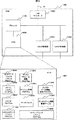
図11は、ボリューム割り当て処理の手順を示すフローチャートである。新しいLVをあるCH(以下CHNiとする)に割り当てる場合、記憶装置システム1の管理者は、管理端末18の管理ソフトウェアを起動する(ステップ6100)。
FIG. 11 is a flowchart showing the procedure of volume allocation processing. When assigning a new LV to a certain CH (hereinafter referred to as CHNi), the administrator of the
管理者は、CHNiを示す情報とCHNiに割り当てたいLVに関する情報を管理端末18に入力する。具体的には、管理者1は、管理ソフトウェアの実行により、管理端末18が有するディスプレイに表示される、未使用を示すエリアに表示されたLDEV170を示すアイコンを、マウス等を用いて、画面上のCHNiを示すエリアにドラッグし移動する。このとき、管理者は、画面上で、必要な記憶容量分の複数のLDEVを同時に移動することができる。尚、本実施形態では、LDEVは、製品出荷時にあらかじめ記憶装置システム1に設定されているものとする(ステップ6101)。
The administrator inputs information indicating CHNi and information regarding the LV to be assigned to CHNi to the
管理者1に選択されたCHNiとそれに割り当てられるLDEV170の情報は、管理端末18からDPM15に送信される。DPM15は、送信された情報を受信する(ステップ6150)。
Information on CHNi selected by the
DPM15は、管理端末18から情報を受け取ると、ディスクプール管理プログラム1521を実行する。DPM15は、指定されたLDEV170が属するプール番号を特定するとともに、ディスクプール情報集中管理テーブル1522を操作し、指定されたLDEV170の割り当て先CH情報エントリ1312の内容を、「未割り当て」から「CHNi」に変更する(ステップ6151)。
Upon receiving information from the
次に、DPM15は、指定されたLDEV170に新規の論理ボリューム番号LVjを割り当て、ディスクプール情報集中管理テーブル1522のLV番号エントリ1314やCN番号エントリ1315に、割り当てられたLVに関する情報を登録する。(ステップ6152)。
Next, the
その後、DPM15は、管理ネットワーク16を介して、CHNiに対し、LDEV170が追加され、追加されたLDEV170が論理ボリュームLVjとして定義されたことを通知する(ステップ6153)。
Thereafter, the
CHNiは、この通知を受信すると(ステップ6160)、ディスクプール情報取得プログラム110048を実行して、以下の処理を行う。CHNiは、CHNi自身が有するディスクプール情報管理テーブル110049に登録された情報を、DPM15から通知された内容に従って変更する(ステップ616)。また、CHNiは、SM13に格納されたディスクプール情報集中管理テーブル1311の該当する個所を変更するように、SM13を制御する(ステップ6162)。
Upon receiving this notification (step 6160), CHNi executes the disk pool
次にCHNiは、ディスクボリューム制御プログラム110045を実行して、割り当てられたLDEV群を論理ボリュームLVjとして構成するための情報及び割り当てられたLDEV群をLVjとして使用するための情報(LV番号等)を、ディスクプール情報管理テーブル110049に登録する(ステップ6163)。
Next, CHNi executes the disk
その後、CHNiはDPM15へ終了報告を送信する(ステップ6164)。終了報告を受信したDPM15は、管理端末18へ終了報告を送信する(ステップ6155)。以上でボリューム割り当て処理が終了する。
Thereafter, CHNi transmits an end report to DPM 15 (step 6164). The
なお、上記では新規のボリューム割り当ての処理動作を説明したが、既存の論理ボリュームLVpに記憶容量を追加する処理も上記同様の処理で実現することができる。既存の論理ボリュームLVpに記憶容量を追加する場合、管理端末18の画面上でLVpに新規のLDEV170を追加するようにユーザが指示すること、ユーザのLDEV170追加の指示を受け、DPM15が、LVpにLDEV170を追加するようにディスクプール情報集中管理テーブル1522を変更するとともにCHNiに変更に関する情報を送信すること、及び変更に関する情報を受信したCHNiが、LVpにLDEV170を追加するようにディスクプール情報管理テーブル110049とSM13のディスクプール情報集中管理テーブルを変更することが、上記の処理と異なる点である。なお、上記の処理は、CHF1110へのLV追加にも同様に適用できる。
Although the processing operation for new volume allocation has been described above, processing for adding storage capacity to an existing logical volume LVp can also be realized by the same processing as described above. When adding storage capacity to an existing logical volume LVp, the user instructs the LVp to add a
図12は、記憶装置システム1の起動時もしくはCH増設作業時等に行われる、CHによるボリューム認識処理の手順を示すフローチャートである。記憶装置システム1へ電源が投入されたこと、あるいは記憶装置システムにCHが増設されたこと(ステップ6200)を契機に、各CHは、CH自身の初期設定を行う(ステップ6201)。
FIG. 12 is a flowchart showing the procedure of volume recognition processing by CH, which is performed when the
初期設定を終了した後、各CHは、ディスクプール情報取得プログラム110048の実行を開始する(ステップ6202)。その後、各CHは、SM13のディスクプール情報集中管理テーブル1311を参照し、自身が使用するLVに関する情報を取得する(ステップ6203)。
After completing the initial setting, each CH starts to execute the disk pool information acquisition program 110048 (step 6202). After that, each CH refers to the disk pool information centralized management table 1311 of the
使用するLVに関する情報を取得したCHは、自身のディスクプール情報管理テーブル110049にその情報を登録する(ステップ6204)。以上の処理により、各CHは、CHに割り当てられたLVを認識することができる(ステップ6205)。 The CH that has acquired information about the LV to be used registers that information in its own disk pool information management table 110049 (step 6204). Through the above processing, each CH can recognize the LV assigned to the CH (step 6205).
このような制御により、各CHは、記憶装置システム1全体のLVに関する情報が一括して登録されているディスクプール情報集中管理テーブル1311に登録された情報に基づいて、記憶装置システム1が有するLVを使用することが出来る。特に、本実施形態では、LVは各CHに重複しないようにディスクプール情報集中管理テーブル1311で排他的に割り当てられているので、各CHはLVを排他的に使用することができる。なお、上記の認識処理は、CHN1100やCHF1110といったCH種によらず同一である。
By such control, each CH has an LV that the
また、上記の実施形態では、ディスク1700を論理デバイスLDEV170という形態に細分化し、その結合体として論理ボリュームLVを定義する例を説明した。しかし、ディスク1700をLDEV170に分割しない実施形態も考えられる。この場合、一つもしくは複数のRG17000の記憶容量全体でディスクプール6が生成され、そのディスクプール6から所定の記憶容量がLVとしてCHに割り当てられるという処理が行われる。
Further, in the above embodiment, the example in which the
上述した実施形態によれば、SANすなわちブロックI/Oインタフェースを備える複数のファイバチャネルアダプタ、及びNASすなわちファイルI/Oインタフェースを備える複数のネットワークチャネルアダプタとの任意の組み合わせを有する記憶装置システムを実現でき、スケーラビリティや構成自由度に優れた記憶装置システムを構築することが可能になる。 According to the above-described embodiment, a storage device system having any combination of a plurality of Fiber Channel adapters with SAN or block I / O interfaces and a plurality of network channel adapters with NAS or file I / O interfaces is realized. This makes it possible to construct a storage device system that is excellent in scalability and configuration flexibility.
また、記憶装置システムが有する記憶領域の設定や管理運用を単一の管理端末から統括的に行うことで、管理運用の容易性が向上し管理コストを低減することができる。 In addition, since the setting and management operation of the storage area of the storage device system are performed collectively from a single management terminal, the ease of management operation can be improved and the management cost can be reduced.
さらに、SANとNASとが混在する記憶装置システムが有する記憶容量を、排他制御を行いながら、安全に使用することができるので、記憶容量の集中管理による容易利用可能な環境を提供するとともに、記憶容量の最適分配を実現でき、管理運用コストを低減することができる。 Furthermore, since the storage capacity of a storage device system in which SAN and NAS are mixed can be used safely while performing exclusive control, an environment that can be easily used is provided by centralized management of storage capacity, and storage Optimal capacity distribution can be realized and management and operation costs can be reduced.
次に、本発明の第二の実施形態を説明する。前述の実施形態においては、1台のCHF1110又は1台のCHN1100各々に、異なるLVを割り当てる方法を示したが、本実施形態では、複数のCHに同一のLVを割り当てる場合のディスクプールの管理方法、およびLVの共有の方法を説明する。
Next, a second embodiment of the present invention will be described. In the above-described embodiment, the method of assigning different LVs to one
本実施形態においては、図9に開示されているCH間共有情報1317〜1319が用いられる。また、本実施形態においては、ディスクプール6、RG17000、LVの各々に対応してCH間共有情報1317〜1319が設定される。
In this embodiment, the inter-CH shared
CH間共有情報には、主に以下の3つの属性に関する情報が含まれる。
(1)リード/ライト可能共有属性(以下「R/W」)
(2)リードオンリ共有属性(以下「R」)
(3)共有禁止属性(以下「P」)
これらの属性は、P>R>R/Wの順に順位付けされている。そして、これらの属性は、一度LVに設定されると、設定された属性の順位よりも上位の順位の属性にしか変更することが出来ない。つまり、一度Rの属性が設定されたLVは、Pの属性には変更されうるが、R/Wの属性には変更できない。これは、一旦共有が禁止されたLVを共有可能とすると、あるCHがあるLVを専有していることを前提としてそのLVを使用していた場合、そのLVの属性がR等に変更されると、公開したくないデータが公開されたり、データが改変され、論理的な矛盾が生じる可能性があるからである。
The inter-CH shared information mainly includes information on the following three attributes.
(1) Read / write shared attribute (hereinafter “R / W”)
(2) Read-only shared attribute (hereinafter “R”)
(3) Share prohibition attribute (hereinafter “P”)
These attributes are ranked in the order of P>R> R / W. And once these attributes are set to LV, they can only be changed to attributes of higher rank than the rank of the set attributes. In other words, an LV once set with an R attribute can be changed to a P attribute, but cannot be changed to an R / W attribute. This is because once an LV that has been prohibited from being shared can be shared, the attribute of the LV is changed to R, etc. This is because data that is not desired to be disclosed may be disclosed, or the data may be altered, resulting in a logical contradiction.
また、上位の属性が設定されているLVに下位の属性を設定したい場合には、ユーザは、一旦LVを削除して、LVに割り当てられていたLDEV等の記憶領域をディスクプール6に戻し、新たにLVを再構成する必要がある。なお、この3つ以外の属性を設けることも可能である。 Also, if you want to set the lower attribute to the LV for which the higher attribute is set, the user once deletes the LV and returns the storage area such as LDEV assigned to the LV to the disk pool 6, A new LV needs to be reconfigured. It is also possible to provide attributes other than these three.
また、CH間共有情報は、ディスクプール6>RG17000>LV又はLDEV170の順で継承される。すなわち、上位(ディスクプールが最上位)の共有情報が、下位のRG17000とLDEV170が有する共有情報に優先する。またRG17000の共有情報がLDEV170が有する共有情報に優先する。
In addition, the inter-CH shared information is inherited in the order of disk pool 6> RG17000> LV or LDEV170. That is, the upper shared information (the disk pool is the highest) has priority over the shared information held by the lower RG 17000 and
例えば、ディスクプール6の共有属性がPであるとすると、その下位のRG17000等の属性もすべてPとなる。よって、記憶装置システム1内のディスクプール6が有する記憶領域は、一切共有することができなくなる。また、P属性の順位が高く設定されているので、下位のRG17000等にPよりも順位の低い属性を個別に付与又は変更することができない。また、ディスクプール6の共有属性がR/Wだとすると、その下位のRG17000等の属性もすべてR/Wとなる。よって、記憶装置システム1が有する記憶領域すべて共有することができる。またこの場合、下位のRG17000等に任意の属性R、Pを個別に付与することが可能となる。
For example, if the shared attribute of the disk pool 6 is P, all the attributes such as RG 17000 below it are also P. Therefore, the storage area of the disk pool 6 in the
このように、ディスクプール6や、RG17000といった、記憶装置システム1が有する記憶領域の論理的レベルの各々で共有の可否を設定することで、LV割り当ての際に、記憶装置システム1の記憶領域の一切の共有を認めないようにしたり、記憶装置システム1の記憶領域の一切を自由に共有することができるようにしたりすることができ、ボリューム割り当ての容易さと、セキュリティの強度をコントロールすることができる。
In this way, by setting whether or not sharing is possible at each logical level of the storage area of the
以下、いくつかの場合に分け、CH間の共有ボリュームの設定について説明する。ここでは、CHF1110とCHN1100、すなわちSANとNASの間で単一の論理ボリュームを共有する場合について、以下の二つの形態に分けて説明する。
The setting of the shared volume between CHs will be described below in several cases. Here, the case where a single logical volume is shared between
第一の例は、NAS over SANと呼ばれる形態である。これは、CHN1100に割り当てられたLV上に作成されたファイルシステムに対し、記憶装置システム1の外部にある計算機がLAN20経由でファイルアクセス要求をCHN1100に送信し、アクセス要求をした計算機が、SAN30を経由してデータを送受信するというものである。
The first example is a form called NAS over SAN. This is because a computer outside the
第二の例は、SAN経由バックアップと呼ばれる形態である。これは、CHN1100に割り当てられたファイルシステムが構築されるLVに格納されているデータを、CHF1110に接続されたSAN経由でバックアップするというものである。
The second example is a form called backup via SAN. This is to back up the data stored in the LV in which the file system assigned to the
上述の例は、SAN−NAS間の計算機同士における論理ボリュームの共有に関するので、上記CH間共有情報のうち、S-N共有情報1317が使用される。
Since the above example relates to sharing of logical volumes between computers between SAN and NAS, S-N shared
図9において、ディスクプール6(番号1)、RG17000(番号2)、LDEV170(番号6〜8)で構築されたLV8が、SAN対応の計算機とNAS対応の計算機とで共有されるLVとして定義されている。これは、CH番号エントリ1316に複数種類のCHが登録されていることから明らかである。 In FIG. 9, LV8 constructed with disk pool 6 (number 1), RG17000 (number 2), and LDEV170 (numbers 6-8) is defined as an LV shared between SAN-compatible computers and NAS-compatible computers. ing. This is apparent from the fact that a plurality of types of CH are registered in the CH number entry 1316.
また、LV8に対応するS-N共有情報エントリ1317には、ディスクプール1がR/W、RG2がR/W、LV8がR/Wであるという情報が登録されている。尚、同一ディスクプールで同一RG17000内のLV8以外のLVはすべてP属性に変更されており、共有が禁止されている。さらに、未使用のLDEV170には、全てR/W属性が設定されている。
In the S-N shared
このような共有属性の設定は、ディスクプール6に関してはディスクプール定義時に、RG17000に関しては、RG17000をディスクプール6に登録する時、LVやLDEVに関しては、ボリューム割り当て処理動作時に、それぞれ行われる。具体的な設定情報の指示は、ユーザが管理端末18を介して行う。SAN-SAN間の共有情報(S-S共有情報)や、NAS−NAS間の共有情報(N-N共有情報)も上記と同様に各々のエントリ1318、1319に設定される。
Such setting of the shared attribute is performed for the disk pool 6 when defining the disk pool, for RG17000, when registering the RG17000 in the disk pool 6, and for LV and LDEV, during the volume allocation processing operation. A specific setting information instruction is given by the user via the
上述した第二の実施形態においては、LVの共有について複数レベルの属性を設定する例を示した。次の第三の実施形態においては、これらの属性に加え、LVを使用するユーザについて複数レベルの属性を設定して、各レベルのユーザに対して異なるアクセス制限をする例について説明する。本実施形態においては、NAS−NAS間の共有について説明する。 In the second embodiment described above, an example in which multiple levels of attributes are set for LV sharing has been described. In the next third embodiment, an example will be described in which, in addition to these attributes, multiple levels of attributes are set for users who use LVs, and different levels of access are restricted for users at each level. In the present embodiment, sharing between NAS and NAS will be described.
図9において、ディスクプール情報集中管理テーブル1311(1522)のユーザクラス共有情報エントリ1320は、ユーザに関する属性(ユーザクラス)ごとのサブエントリを有する。ユーザクラスとしては次の5つの属性がある。
(1)Everyone : 全ユーザ(以下「E」)
(2)Company : 同一企業内ユーザ(以下「C」)
(3)Domain : 同一ドメイン内ユーザ(以下「E」)
(4)WorkGroup : 同一ワークグループ内ユーザ(以下「W」)
(5)UserGroup : 同一ユーザグループ内ユーザ(以下「U」)
尚、一般的に、(1)から(5)の順で、対象となるユーザの数は少なくなる。
In FIG. 9, the user class shared information entry 1320 of the disk pool information central management table 1311 (1522) has a subentry for each attribute (user class) related to the user. The user class has the following five attributes.
(1) Everyone: All users (“E”)
(2) Company: Users within the same company (hereinafter “C”)
(3) Domain: Users within the same domain (hereinafter “E”)
(4) WorkGroup: Users within the same workgroup (hereinafter “W”)
(5) UserGroup: Users in the same user group (hereinafter “U”)
In general, the number of target users decreases in the order of (1) to (5).
各ユーザクラスには、さらに、第二の実施形態において説明したCH間ボリューム共有属性と同様の属性、すなわち、R/W、R、Pの3種類の属性が付与される。これらの属性の意味、順位、継承、変更可否等の考え方は第二の実施形態と同一であるので、説明は省略する。 Each user class is further given the same attributes as the inter-CH volume sharing attributes described in the second embodiment, that is, three types of attributes R / W, R, and P. The concept of the meaning, order, inheritance, changeability, etc. of these attributes is the same as in the second embodiment, and a description thereof will be omitted.
図9に示されるLV0を例に説明する。ユーザクラス共有情報エントリ1320の各サブエントリには、E=P、C=R、D=R、W=R/W、U=R/Wの情報が登録されている。すなわち、LV0は、同一ユーザグループおよび同一ワークグループのユーザがR/WできるLVであるが、これらに属さない同一ドメイン内および同一企業のユーザはこのLVの内容を変更することが出来ない。 An example of LV0 shown in FIG. 9 will be described. In each subentry of the user class shared information entry 1320, information of E = P, C = R, D = R, W = R / W, and U = R / W is registered. That is, LV0 is an LV that allows users in the same user group and the same work group to read / write, but users in the same domain and the same company that do not belong to these cannot change the contents of this LV.
このようなユーザクラス共有属性の設定は、ディスクプール6に関してはディスクプール定義時に、RG17000に関しては、RG17000がディスクプール6へ登録される時に、LVやLDEVに関してはボリューム割り当て処理動作時に、それぞれ行われる。この設定の指示は、ユーザが管理端末16を介して行う。
Such user class shared attribute settings are made when defining a disk pool for disk pool 6, when RG17000 is registered in disk pool 6 for RG17000, and during volume allocation processing for LV and LDEV. . This setting instruction is given by the user via the
尚、記憶装置システム1は、ユーザの管理を行うために、ユーザが、上記1〜5のユーザクラスの、何という名前のグループに属しているか等の情報が格納されたユーザクラス定義情報テーブルを有する必要がある。このユーザクラス定義情報テーブルには、LV毎にユーザの情報が登録されている。
The
具体的には、NASにはファイルシステム毎にユーザを管理する機構が備わっているため、ユーザは、CHN1100にユーザ管理情報を設定する必要がある。そのユーザ情報を設定する際に、ユーザクラス定義情報テーブルをあわせて作成すればよい。
Specifically, since the NAS has a mechanism for managing users for each file system, the user needs to set user management information in the
本実施形態によれば、記憶装置システム1にLVを設定する際に、管理者が適切なユーザクラスを選択する。こうすることにより、LVレベルでユーザクラスに応じたセキュリティを設定することができる。この機能により、万一、許可されていないユーザクラスのユーザがこのLVをアクセスしようとしても、LVごとにユーザの認証が行われるため、アクセス権のないユーザのアクセスは抑止される。
According to the present embodiment, the administrator selects an appropriate user class when setting the LV in the
このようなセキュリティ機能により、一台の大規模記憶装置システム1をデータセンタに設置し、複数の企業が単一のディスクプールを共有しながら、アクセスセキュリティを維持することが可能になる。
With such a security function, a single large-scale
NASにはもともとユーザ管理の機能が備わっているので、本実施形態をNASへ適用するのは容易である。一方、SANにも同様にユーザ管理の機能を実装することにより、まったく同様にユーザクラス間のアクセスセキュリティを実現したディスクプール管理およびボリューム割り当てを実現することができる。 Since the NAS originally has a user management function, it is easy to apply this embodiment to the NAS. On the other hand, by implementing the user management function in the SAN as well, disk pool management and volume allocation that realizes access security between user classes can be realized in exactly the same way.
また、本実施形態では、単一のCH内でのユーザクラス間アクセスセキュリティの実現を説明したが、第二実施形態のCH間ボリューム共用の構成と第三実施形態のユーザクラス間アクセスセキュリティの構成をまとめた実施形態も可能である。すなわち、記憶装置システム1は、CH間でボリュームを共用しながら、適切なユーザクラスのユーザのみにアクセスを許可するというような使い方をユーザに提供できる。
Further, in the present embodiment, the realization of access security between user classes within a single CH has been described, but the configuration of volume sharing between CHs of the second embodiment and the configuration of access security between user classes of the third embodiment Embodiments summarizing these are also possible. That is, the
[発明の効果]
本発明によれば、記憶装置システムの管理運用コストを低減できる。また、本発明によれば、記憶容量の管理が容易な記憶装置システムを提供できる。
[The invention's effect]
According to the present invention, the management operation cost of the storage device system can be reduced. Further, according to the present invention, it is possible to provide a storage device system in which storage capacity can be easily managed.
さらに、本発明によれば、記憶装置システムの運用の自由度をあげることができる。 Furthermore, according to the present invention, the degree of freedom of operation of the storage device system can be increased.
1…記憶装置システム、11…ディスクコントローラ、1700…ディスク、1100…ネットワークチャネルアダプタ(CHN)、400…NASクライアント、1110…ファイバチャネルアダプタ(CHF)、500…SANクライアント、13…共有メモリ(SM)、14…キャッシュメモリ(CM)、15…ディスクプール管理部(DPM)、16…管理ネットワーク、18…管理端末。 1 ... Storage system, 11 ... Disk controller, 1700 ... Disk, 1100 ... Network channel adapter (CHN), 400 ... NAS client, 1110 ... Fibre channel adapter (CHF), 500 ... SAN client, 13 ... Shared memory (SM) , 14 ... Cache memory (CM), 15 ... Disk pool management unit (DPM), 16 ... Management network, 18 ... Management terminal.
Claims (10)
Priority Applications (1)
| Application Number | Priority Date | Filing Date | Title |
|---|---|---|---|
| JP2008002274A JP2008140413A (en) | 2008-01-09 | 2008-01-09 | Storage device system |
Applications Claiming Priority (1)
| Application Number | Priority Date | Filing Date | Title |
|---|---|---|---|
| JP2008002274A JP2008140413A (en) | 2008-01-09 | 2008-01-09 | Storage device system |
Related Parent Applications (1)
| Application Number | Title | Priority Date | Filing Date |
|---|---|---|---|
| JP2002125172A Division JP2003316713A (en) | 2002-04-26 | 2002-04-26 | Storage device system |
Publications (2)
| Publication Number | Publication Date |
|---|---|
| JP2008140413A true JP2008140413A (en) | 2008-06-19 |
| JP2008140413A5 JP2008140413A5 (en) | 2008-12-11 |
Family
ID=39601728
Family Applications (1)
| Application Number | Title | Priority Date | Filing Date |
|---|---|---|---|
| JP2008002274A Pending JP2008140413A (en) | 2008-01-09 | 2008-01-09 | Storage device system |
Country Status (1)
| Country | Link |
|---|---|
| JP (1) | JP2008140413A (en) |
Cited By (1)
| Publication number | Priority date | Publication date | Assignee | Title |
|---|---|---|---|---|
| JP2014529803A (en) * | 2011-08-26 | 2014-11-13 | ヴイエムウェア インコーポレイテッドVMware,Inc. | Data storage systems that export logical volumes as storage objects |
-
2008
- 2008-01-09 JP JP2008002274A patent/JP2008140413A/en active Pending
Cited By (2)
| Publication number | Priority date | Publication date | Assignee | Title |
|---|---|---|---|---|
| JP2014529803A (en) * | 2011-08-26 | 2014-11-13 | ヴイエムウェア インコーポレイテッドVMware,Inc. | Data storage systems that export logical volumes as storage objects |
| JP2016212904A (en) * | 2011-08-26 | 2016-12-15 | ヴイエムウェア インコーポレイテッドVMware,Inc. | Data storage system that exports logical volumes as storage objects |
Similar Documents
| Publication | Publication Date | Title |
|---|---|---|
| US6810462B2 (en) | Storage system and method using interface control devices of different types | |
| JP3837953B2 (en) | Computer system | |
| US7437462B2 (en) | Method for zoning data storage network using SAS addressing | |
| JP5199000B2 (en) | File server resource dividing method, system, apparatus and program | |
| JP5272709B2 (en) | Address assignment method, computer, physical machine, program, and system | |
| US7249240B2 (en) | Method, device and program for managing volume | |
| EP1131719A1 (en) | Logical unit mapping in a storage area network (san) environment | |
| US9092158B2 (en) | Computer system and its management method | |
| JP2007102762A (en) | Resource management method in logically partition divisioned storage system | |
| US7406578B2 (en) | Method, apparatus and program storage device for providing virtual disk service (VDS) hints based storage | |
| US7657945B2 (en) | Systems and arrangements to adjust resource accessibility based upon usage modes | |
| KR20210022121A (en) | Methods and systems for maintaining storage device failure tolerance in a configurable infrastructure | |
| US7366867B2 (en) | Computer system and storage area allocation method | |
| JP2008140413A (en) | Storage device system | |
| JP3897049B2 (en) | Computer system | |
| US8555014B1 (en) | Automatic access management of clients to a storage system | |
| US11704426B1 (en) | Information processing system and information processing method | |
| JP2005322254A (en) | Computer system, computer used for this computer system, and storage device | |
| JP4438785B2 (en) | Computer system | |
| JP4564035B2 (en) | Computer system, and computer and storage device used in the computer system | |
| JP4723532B2 (en) | Computer system, and computer and storage device used in the computer system |
Legal Events
| Date | Code | Title | Description |
|---|---|---|---|
| A521 | Written amendment |
Free format text: JAPANESE INTERMEDIATE CODE: A523 Effective date: 20081023 |
|
| RD04 | Notification of resignation of power of attorney |
Free format text: JAPANESE INTERMEDIATE CODE: A7424 Effective date: 20090212 |
|
| A131 | Notification of reasons for refusal |
Free format text: JAPANESE INTERMEDIATE CODE: A131 Effective date: 20100628 |
|
| A521 | Written amendment |
Free format text: JAPANESE INTERMEDIATE CODE: A523 Effective date: 20100820 |
|
| A02 | Decision of refusal |
Free format text: JAPANESE INTERMEDIATE CODE: A02 Effective date: 20110210 |