JP2008123257A - Remote operation support system and display control method - Google Patents
Remote operation support system and display control method Download PDFInfo
- Publication number
- JP2008123257A JP2008123257A JP2006306495A JP2006306495A JP2008123257A JP 2008123257 A JP2008123257 A JP 2008123257A JP 2006306495 A JP2006306495 A JP 2006306495A JP 2006306495 A JP2006306495 A JP 2006306495A JP 2008123257 A JP2008123257 A JP 2008123257A
- Authority
- JP
- Japan
- Prior art keywords
- display
- video
- reference video
- size
- unit
- Prior art date
- Legal status (The legal status is an assumption and is not a legal conclusion. Google has not performed a legal analysis and makes no representation as to the accuracy of the status listed.)
- Pending
Links
Images


Landscapes
- Controls And Circuits For Display Device (AREA)
- Liquid Crystal (AREA)
- Digital Computer Display Output (AREA)
- Liquid Crystal Display Device Control (AREA)
- Control Of Indicators Other Than Cathode Ray Tubes (AREA)
Abstract
Description
本発明は、遠隔作業支援システム、表示制御方法に関し、特に頭部装着式映像表示装置を備えた遠隔作業支援システム、表示制御方法に関する。 The present invention relates to a remote work support system and a display control method, and more particularly to a remote work support system and a display control method provided with a head-mounted video display device.
従来、観察者の頭部や顔面に着脱自在に装着され、小型のCRTや液晶表示素子等の映像表示素子から得られる映像(以下、画像とも称す。)を、接眼光学系によって観察者の眼球に直接投影させることで、恰も該映像が空中に拡大投影されているかの様な虚像の観察を可能にした頭部装着式映像表示装置、すなわちHMD(Head Mount Display)が知られている。 Conventionally, an image (hereinafter also referred to as an image) that is detachably attached to the observer's head or face and obtained from an image display element such as a small CRT or a liquid crystal display element is displayed on the observer's eyeball by an eyepiece optical system. A head-mounted image display device, that is, an HMD (Head Mount Display) is known in which a virtual image can be observed as if the image is enlarged and projected in the air.
HMDは、DVD、ビデオ等のコンテンツ映像の観賞用や、産業機器若しくは医療機器等の遠隔操作用としての表示装置として利用され、その用途は多岐に渡っている。 The HMD is used as a display device for viewing content videos such as DVDs and videos, and for remote operation of industrial equipment or medical equipment, and has a wide variety of uses.
遠隔操作用としては、作業者が電子カメラを備えたHMDを装着し、指示者が電子カメラが捕えた作業対象物の映像を、遠隔地に設けられた例えばホストコンピュータ等のモニタで観察しながら、作業者に音声や映像による適切な情報を提供し作業指示を行う、といった遠隔作業支援システムが種々提案されている(例えば、特許文献1参照)。 For remote operation, an operator wears an HMD equipped with an electronic camera, and an instructor observes an image of a work object captured by the electronic camera on a monitor such as a host computer provided at a remote location. Various remote work support systems have been proposed in which appropriate information is provided to workers by voice or video and work instructions are given (see, for example, Patent Document 1).
この様な遠隔作業支援システムにおいて、作業者が、HMDの映像表示部に表示される電子カメラが捕えた作業対象物の映像と、ホストコンピュータから伝送された作業対象物を表す参照映像とを比較しながら作業を行う場合、電子カメラで撮影された映像とホストコンピュータから伝送された参照映像それぞれにおける作業対象物の表示サイズが異なると、両者を比較することは容易ではなく作業性の低下を招く恐れがあった。 In such a remote work support system, the worker compares the video of the work object captured by the electronic camera displayed on the video display unit of the HMD with the reference video representing the work object transmitted from the host computer. However, when the work is performed, if the display size of the work object in the video captured by the electronic camera and the reference video transmitted from the host computer are different, it is not easy to compare the two and the workability is reduced. There was a fear.
そこで、電子カメラによる作業対象物の表示サイズに、参照映像による作業対象物の表示サイズを近づける様に、作業者がHMDの操作部により参照映像の表示サイズを調整する方法や、指示者が電子カメラが捕えた作業対象物の映像をモニタで観察しながら、作業者のHMDの映像表示部に表示される参照映像の表示サイズを遠隔で調整をする、といった方法が従来行われていた。
しかしながら、従来行われていた前述の方法は、いずれも、煩雑な調整を必要とし、作業者や指示者への負担を増大し、使い勝手が良いとは言い難いものであった。 However, any of the above-described conventional methods requires complicated adjustment, increases the burden on the operator and the instructor, and is difficult to use.
本発明は、上記課題を鑑みてなされたもので、作業者や指示者へ負担を課することなく、作業に適切なサイズの参照映像を表示することが可能な遠隔作業支援システム、表示制御方法を提供することを目的とする。 The present invention has been made in view of the above problems, and provides a remote work support system and a display control method capable of displaying a reference video of a size suitable for work without imposing a burden on the worker or the instructor. The purpose is to provide.
上記目的は、下記の1乃至6のいずれか1項に記載の発明によって達成される。 The above object is achieved by the invention described in any one of 1 to 6 below.
1.映像を表示する表示ユニットを備えた頭部装着式映像表示装置と、
前記頭部装着式映像表示装置に作業対象物を表す参照映像を提供するサーバ装置と、を有し、
前記頭部装着式映像表示装置を装着した作業者に、指示者が前記サーバ装置により作業指示を与える遠隔作業支援システムであって、
前記頭部装着式映像表示装置は、該頭部装着式映像表示装置から前記作業対象物までの距離を検出する距離検出部と、
前記表示ユニットに表示させる前記参照映像の表示サイズを調整する表示制御部と、を有し、
前記参照映像には、前記作業対象物の現実の大きさに対する該参照映像の縮尺比情報が添付され、
前記表示制御部は、前記距離検出部で検出された距離と前記サーバ装置から提供された前記参照映像に添付されている前記縮尺比情報に基づいて、前記表示ユニットに表示させる前記参照映像の表示サイズを調整することを特徴とする遠隔作業支援システム。
1. A head-mounted video display device having a display unit for displaying video;
A server device that provides a reference video representing a work object to the head-mounted video display device,
A remote work support system in which an operator gives a work instruction by the server device to a worker wearing the head-mounted video display device,
The head-mounted video display device includes a distance detection unit that detects a distance from the head-mounted video display device to the work object;
A display control unit for adjusting a display size of the reference video to be displayed on the display unit,
The reference video is attached with scale ratio information of the reference video with respect to the actual size of the work object,
The display control unit displays the reference video to be displayed on the display unit based on the distance detected by the distance detection unit and the scale ratio information attached to the reference video provided from the server device. A remote operation support system characterized by adjusting the size.
2.前記頭部装着式映像表示装置は、作業対象物を撮影する電子カメラを備え、
前記表示制御部は、前記距離検出部で検出された距離と前記サーバ装置から提供された前記参照映像に添付されている前記縮尺比情報に基づいて、前記表示ユニットに表示させる前記参照映像の表示サイズを、前記電子カメラで撮影され前記表示ユニットに表示させる映像の表示サイズに合わせる様に調整することを特徴とする前記1に記載の遠隔作業支援システム。
2. The head-mounted image display device includes an electronic camera for photographing a work object,
The display control unit displays the reference video to be displayed on the display unit based on the distance detected by the distance detection unit and the scale ratio information attached to the reference video provided from the server device. 2. The remote work support system according to 1 above, wherein the size is adjusted to match a display size of an image captured by the electronic camera and displayed on the display unit.
3.前記電子カメラは、ズームレンズを備え、
前記表示制御部は、前記ズームレンズのズーム倍率および前記距離検出部で検出された距離および前記サーバ装置から提供された前記参照映像に添付されている前記縮尺比情報に基づいて、前記表示ユニットに表示させる前記参照映像の表示サイズを、前記電子カメラで撮影され前記表示ユニットに表示させる映像の表示サイズに合わせる様に調整することを特徴とする前記2に記載の遠隔作業支援システム。
3. The electronic camera includes a zoom lens,
The display control unit controls the display unit based on the zoom magnification of the zoom lens, the distance detected by the distance detection unit, and the scale ratio information attached to the reference image provided from the server device. 3. The remote work support system according to
4.前記表示ユニットは、前記頭部装着式映像表示装置を装着した作業者が外界をシースルー可能であり、
前記表示制御部は、前記距離検出部で検出された距離と前記サーバ装置から提供された前記参照映像に添付されている前記縮尺比情報に基づいて、前記表示ユニットに表示させる前記参照映像の表示サイズを、作業者がシースルーで観察できる前記作業対象物の光学像のサイズに合わせる様に調整することを特徴とする前記1に記載の遠隔作業支援システム。
4). The display unit is capable of see-through the outside world by an operator wearing the head-mounted video display device,
The display control unit displays the reference video to be displayed on the display unit based on the distance detected by the distance detection unit and the scale ratio information attached to the reference video provided from the server device. 2. The remote work support system according to 1 above, wherein the size is adjusted to match the size of the optical image of the work object that can be observed through the see-through.
5.前記距離検出部は、前記頭部装着式映像表示装置から前記作業対象物までの距離の変化率を検出し、
前記表示制御部は、前記距離検出部で検出された変化率と予め設定された閾値を比較し、前記変化率が前記閾値を上回った場合、前記参照映像の表示サイズを調整することを特徴とする前記1乃至4のいずれか1項に記載の遠隔作業支援システム。
5. The distance detection unit detects a change rate of a distance from the head-mounted image display device to the work object,
The display control unit compares a change rate detected by the distance detection unit with a preset threshold value, and adjusts a display size of the reference video when the change rate exceeds the threshold value. The remote work support system according to any one of 1 to 4 above.
6.作業者が装着した頭部装着式映像表示装置に設けられた表示ユニットに表示させるサーバ装置から提供された作業対象物を表す参照映像の表示制御方法であって、
前記参照映像には、前記作業対象物の現実の大きさに対する該参照映像の縮尺比情報が添付され、
前記頭部装着式映像表示装置から前記作業対象物までの距離を検出する距離検出工程と、
前記距離検出工程で検出された距離と前記サーバ装置から提供された前記参照映像に添付されている前記縮尺比情報に基づいて、前記表示ユニットに表示させる前記参照映像の表示サイズを調整する表示サイズ調整工程と、を有することを特徴とする参照映像の表示制御方法。
6). A display video display control method representing a work object provided from a server device to be displayed on a display unit provided in a head-mounted video display device worn by an operator,
The reference video is attached with scale ratio information of the reference video with respect to the actual size of the work object,
A distance detection step of detecting a distance from the head-mounted image display device to the work object;
A display size for adjusting the display size of the reference video to be displayed on the display unit based on the distance detected in the distance detection step and the scale ratio information attached to the reference video provided from the server device And a reference video display control method.
本発明によれば、表示制御部は、距離検出部で検出された距離とサーバ装置から提供された参照映像に添付されている縮尺比情報に基づいて、表示ユニットに表示させる参照映像の表示サイズを調整する様にした。したがって、頭部装着式映像表示装置を装着した作業者は、作業対象物との距離に係らず、いつも作業に適切な表示サイズの参照映像を観察することができる。これにより、従来行われていた前述の様な煩雑な調整作業を行うことなく、作業に適切なサイズの参照映像を得ることができる。その結果、作業者や指示者にかかる負担を軽減でき、作業の効率化を図ることができる。 According to the present invention, the display control unit displays the display size of the reference image displayed on the display unit based on the distance detected by the distance detection unit and the scale ratio information attached to the reference image provided from the server device. Was adjusted. Therefore, an operator wearing the head-mounted image display device can always observe a reference image having a display size appropriate for the work regardless of the distance from the work object. This makes it possible to obtain a reference video having a size suitable for the work without performing the complicated adjustment work as described above. As a result, the burden on the worker and the instructor can be reduced, and work efficiency can be improved.
以下図面に基づいて、本発明に係る遠隔作業支援システムの実施の形態を説明する。尚、本発明を図示の実施の形態に基づいて説明するが、本発明は該実施の形態に限られない。 Embodiments of a remote work support system according to the present invention will be described below with reference to the drawings. In addition, although this invention is demonstrated based on embodiment of illustration, this invention is not limited to this embodiment.
最初に、遠隔作業支援システム1の構成を図1を用いて説明する。図1は、本発明に係る遠隔作業支援システム1の全体構成の概要を示す模式図である。
First, the configuration of the remote
遠隔作業支援システム1は、図1に示す様に、HMD2、サーバ装置4等から構成される。サーバ装置4は、ホストコンピュータ5、映像・音声記録サーバ6、及びコンテンツサーバ7等から構成される。
As shown in FIG. 1, the remote
ホストコンピュータ5と映像・音声記録サーバ6、コンテンツサーバ7は、イーサーネットENを介して結ばれ、ホストコンピュータ5とHMD2は、インターネットINや携帯、PHS、無線LAN等の公衆回線網PN等を介して結ばれている。 The host computer 5 is connected to the video / audio recording server 6 and the content server 7 via the Ethernet EN, and the host computer 5 and the HMD 2 are connected to the Internet IN, mobile phone, PHS, a public network PN such as a wireless LAN, etc. Are tied together.
この様な構成の遠隔作業支援システム1は、作業者Bが後述のカメラユニット28を備えたHMD2を装着し、カメラユニット28が捕えた作業対象物の映像を、指示者Aが遠隔地に設けられたサーバ装置4の後述のモニタ53で観察しながら、サーバ装置4により作業者Bに映像や音声による適切な情報を提供し、作業指示を行うものである。
In the remote
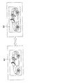
次に、本発明における頭部装着式映像表示装置に該当するHMD2の構成を図2を用いて説明する。図2は、本発明に係るHMD2の全体構成図である。
Next, the configuration of the
HMD2は、図2に示す様に、テンプル21R,21L、ブリッジ22、鼻当て23R,23L、透明基板24R,24L、表示ユニット25(LCD表示部26、接眼光学系27)、カメラユニット28、イヤホン29R,29L、マイク30、及び制御ユニット31等を有している。
As shown in FIG. 2, the
HMD2は、カメラユニット28で撮影された映像や、サーバ装置4から伝送された映像を、表示ユニット25に設けられたLCD表示部26に表示させ、該LCD表示部26から得らた映像を、接眼光学系27によって装着者(以下、作業者Bとも称する。)の眼球に直接投影させることで、恰も該映像が空中に拡大投影されているかの様な虚像の観察を可能にしている。
The
テンプル21R,21Lは、可撓性を有する弾性材等により構成された長尺状の部材であり、装着者の耳や側頭部に掛止され、HMD2の装着者に対する頭部への保持及び装着位置の調整を行う為のものである。尚、テンプル21R,21Lは、回動部21Ra,21Laにおいて矢印P,Q方向に回動可能に構成されており、HMD2を使用しない場合には、テンプル21R,21Lを矢印P,Q方向に回動させて透明基板24R,24Lに沿わせることにより、コンパクト化することができる。
The
ブリッジ22は、HMD2の装着者に対する顔面への保持を行う鼻当て23R,23Lを備え、透明基板24R,24Lの互いに対向する所定位置に架け渡された短尺の棒状部材であり、透明基板24Rと透明基板24Lとを一定の間隙を介した相対位置関係に保持するものである。
The
透明基板24R,24Lは、一方の眼球に対応した位置にU字型のスペース24Rsを形成する略平板状の透明体である。また、透明基板24Rに囲まれて形成されるU字型のスペース24Rsには、接眼光学系27が嵌め込まれている。
The
表示ユニット25は、LCD表示部26、及び接眼光学系27等を有し、カメラユニット28で撮影された映像や、制御ユニット31に設けられた後述のネットワークI/F36を介してサーバ装置4から伝送された映像を表示する。
The
カメラユニット28は、本発明における電子カメラに該当し、図示しない後述のズームレンズ281、CCD(Charge Coupled Device)282、及び画像処理部284等を有し、装着者の周囲の外界情景を撮影するものであり、ズームレンズ281によって結像された被写体光学像を、CCD282によって光電変換して画像信号(映像信号)を生成し、画像処理部284等により画像信号に所定の画像処理を施し画像(映像)を生成する。
The
イヤホン29R,29Lは、装着者の耳に挿入され、装着者に音声を提供する。
マイク30は、装着者の音声を音声信号に変換する。
The
制御ユニット31は、マイクロコンピュータからなり、電源スイッチ351、操作スイッチ352等を有し、これら各種操作スイッチからの信号、及びサーバ装置4からの制御信号等を受けて、HMD2で行われる表示動作や画像信号処理動作を統括的に制御するものである。
The control unit 31 includes a microcomputer and includes a
ここで、表示ユニット25の構成を、図3を用いて説明する。図3は、本発明に係るHMD2における表示ユニット25の左側面からの側断面図であり、主に表示ユニット25の内部構成を示している。
Here, the configuration of the
図3に示す様に、表示ユニット25は、筐体261、LED(Light Emitting Diode)262、コリメータレンズ263、LCD(Liquid Crystal Display)264からなるLCD表示部26、及びプリズム271、HOE(Holographic Optical Element)272からなる接眼光学系27等から構成される。
As shown in FIG. 3, the
LCD表示部26の筐体261の内部には、LED262、コリメータレンズ263、及びLCD264が内蔵された状態で、該筐体261が接眼光学系27のプリズム271の上端部において上斜め前方(図3では右斜め上方向)に突出する態様で取り付けられている。
In the state where the
LED262は、所定波長色を含む白色発光ダイオード(LED)からなる点光源である。
The
コリメータレンズ263は、LED262の光をほぼ平行光にしてLCD264に投光するものである。
The
LCD264は、カメラユニット28で撮影され生成された映像信号や、制御ユニット31に設けられた後述のネットワークI/F36を介してサーバ装置4から伝送された映像信号に基づき映像(画像)を生成するものであり、例えば透過型の液晶表示パネルである。
The
プリズム271は、ガラスや透明樹脂等からなる略板状の透明部材であり、LCD264からの光を内部で複数回の反射を行わせるものである。プリズム271の上端部は、LCD264からの光の大部分を内部に採光できるように、上方に向かってより肉厚となるように前面側(接眼面と反対側)が突き出るように楔形状に形成された肉厚部271bが形成されている。
The
また、プリズム271の下端部には、傾斜面271aが形成されており、プリズム271は、透明基板24Rに形成された傾斜面24Raに対しHOE272を介して接合(例えば接着)されている。また、プリズム271の表裏面は、透明基板24Rの表裏面に対して面一とされている。これにより、プリズム271は、透明基板24Rと一枚の板状に一体化されている。
An
HOE272は、光学的に軸非対称な所謂自由曲面で構成されて正のパワーを有する体積位相型のホログラム光学素子であり、プリズム271の下端部において所定の傾斜角を有して支持されている。HOE272は、プリズム271により導光された光が照射されることにより、光の干渉現象を用いてホログラム映像を眼球Eに提供する。
The
以上のような構成を有する表示ユニット25においては、LED262から射出された光は、コリメータレンズ263を通してLCD264を照明し、この照明によりLCD264で生成された像光は、プリズム271内で複数回の全反射を行った後、HOE272により回折し虚像として装着者の眼球Eに導かれる。
In the
さらに、プリズム271は、前方から入射する光を装着者の眼球Eに導くようになっている。これにより、装着者は、外界(前方の被写体)をシースルー可能となり、カメラユニット28で撮影され生成された映像や制御ユニット31に設けられた後述のネットワークI/F36を介してサーバ装置4から伝送された映像を外界(前方の被写体)と重畳して視認することとなる。
Further, the
次に、HMD2の電気回路構成について図4を用いて説明する。図4は、本発明に係わるHMD2の電気回路のブロック構成図である。尚、図4では、図1乃至図3に示した部材と同じ部材には同一の番号を付与した。
Next, the electric circuit configuration of the
HMD2の要部電気回路ブロックは、表示ユニット25、カメラユニット28、及び制御ユニット31等から構成される。
The main circuit block of the
表示ユニット25は、LCD表示部26、接眼光学系27から構成され、各部位で行われる動作については前述したので説明は省略する。
The
カメラユニット28は、ズームレンズ281、CCD(Charge Coupled Device)282、AFE(Analog Front End)283、画像処理部284、及びAFモータ287、ズームモータ288等を有する。
The
CCD282は、R(赤)光、G(緑)光、B(青)光の各色透過フィルタをピクセル単位(画素単位)で市松模様状に配置させたカラーエリア撮像センサで、ズームレンズ281により結像された被写体光像を、R(赤)光、G(緑)光、B(青)光の各色成分の画像信号(各画素単位で受光された画素信号の信号列からなる信号)に光電変換するものである。
The
AFE283は、制御ユニット31から送信される基準クロックに基づいて、CCD282の駆動を制御し、CCD282から読み出された映像信号(画像信号)に周知のアナログ信号処理を施した後にデジタル映像信号に変換する。
The
この様に、CCD282で読み出された映像信号は、AFE283で所定の処理が施されて、デジタル映像信号に変換される。デジタル化された映像信号は、画像処理部284に取り込まれて所定の処理が行われる。以下、画像処理部284で行われるデジタル映像信号への処理について説明する。
In this manner, the video signal read by the
最初に、画像処理部284に取り込まれたデジタル映像信号は、CCD282から出力される映像信号の読出しに同期して後述の制御ユニット31中の画像メモリ33に書き込まれる。すなわち、画像処理部284で行われる処理に使用されるデジタル映像信号は、画像メモリ33にいったん記録したものを画像メモリ33から取り出し、画像処理部284中の各部位における処理に使用される。
First, the digital video signal captured by the
画像処理部284は、図示しない例えば、黒レベル補正部、画素補間部、ホワイトバランス制御部、ガンマ補正部、マトリックス演算部、シェーディング補正部、及び画像圧縮部等を有し、画像メモリ33より取り出したデジタル映像信号に周知の画像信号処理を施すものである。そして、これらの部位で所定の処理を施されたデジタル映像信号は、再度、画像メモリ33に格納される。
The
制御ユニット31は、制御部32、画像メモリ33、VRAM(Video Random Access Memory)34、操作部35、ネットワークI/F36、AF・ズームモータ駆動回路371、及び音声出力回路381、音声入力回路382等から構成される。
The control unit 31 includes a
制御部32は、図示しない各制御プログラム等を記憶するROM(Read Only Memory)、演算処理や制御処理等のデータを一時的に格納するRAM(Random Access Memory)、及び制御プログラム等をROMから読み出して実行するCPU(中央演算処理装置)等からなり、前述の各操作スイッチからの信号、及びサーバ装置4からの制御信号等を受けて、HMD2で行われる表示動作や画像信号処理動作を統括的に制御するものである。
The
AF制御部321は、カメラユニット28のAF(Auto Focus;自動焦点)制御を行う。具体的には、AF制御部321は、画像メモリ33に書き込まれた映像データ(デジタル映像信号)より、予め設定されてある撮像面上の測距エリアに関する映像データを読み出し、読み出した映像データのコントラスト検出により合焦位置を求める測距演算を行い、その結果に基づいてAF・ズームモータ駆動回路371を介してAFモータ287を駆動して、AF制御を行う。
The AF control unit 321 performs AF (Auto Focus) control of the
距離検出部322は、AF制御部321によるAF動作によって調整されたズームレンズレンズ281を構成する各レンズ群の停止位置情報より、被写体距離を検出する。また、AF制御部321によるAF動作は所定の周期(例えば、5秒周期)で行われ、距離検出部321は、AF動作が行われる度に被写体距離を検出し、前回検出した距離に対する今回検出した距離の変化率を算出する。
The distance detection unit 322 detects the subject distance from stop position information of each lens group constituting the
表示制御部323は、ズームレンズレンズ281のズーム倍率および距離検出部322で検出された被写体距離(HMD2から作業対象物までの距離)およびサーバ装置4から伝送された後述の参照映像に添付されている作業対象物の現実の大きさに対する参照映像の縮尺比情報に基づいて、参照映像の表示サイズを調整する。また、表示制御部323は、被写体距離の変化率について予め閾値(例えば、30%)を設定しておき、距離検出部322で検出された変化率と予め設定された閾値を比較し、変化率が閾値を上回った場合、参照映像の表示サイズを調整する。
The display control unit 323 is attached to the zoom magnification of the
画像メモリ33は、制御ユニット31中の制御部32によりデジタル映像信号に対する各種処理を行う為の作業領域として用いられる一時メモリである。
The
VRAM34は、LCD表示部26中のLCD264の画素数に対応した映像信号の記録容量を有し、LCD264に再生表示される映像を構成する映像信号のバッファメモリである。
The
ネットワークI/F36は、HMD2を公衆回線網PNに接続し、サーバ装置4との間で交信を行い、映像、音声、及び各種制御信号等の入出力を行う。
The network I / F 36 connects the
AF・ズームモータ駆動回路371は、制御部32の制御に基づいて、AFモータ287、ズームモータ288を駆動する駆動信号を生成する。
The AF / zoom
次に、図1に戻って、サーバ装置4の構成を説明する。サーバ装置4はホストコンピュータ5(以下、ホストPC5と称する。)、音声・映像記録サーバ6、及びコンテンツサーバ7等から構成される。
Next, returning to FIG. 1, the configuration of the
ホストPC5は、図1に示す様に、コンピュータ本体51、モニタ53、マウス55、及びキーボード57等を備えた、例えば、パーソナルコンピュータである。
As shown in FIG. 1, the host PC 5 is, for example, a personal computer including a computer
ホストPC5は、そのモニタ53に、作業者Bに装着されたHMD2のカメラユニット28が撮影した作業対象物の映像を表示する。指示者Aは、モニタ53に表示された作業対象物の映像を観察しながら、マウス55やキーボード57等によりホストPC5を操作し、作業者Bにコンテンツサーバ7に記録されている後述の参照映像等の作業に必要な情報を提供し、作業指示を行うものである。
The host PC 5 displays on the
音声・映像記録サーバ6は、HMD2のカメラユニット28で撮影された映像や作業者Bと指示者Aとの間で交信された音声等の作業記録を記憶する。
The audio / video recording server 6 stores work records such as video captured by the
コンテンツサーバ7には、作業者Bが作業を行う際に必要な映像や音声等の作業支援情報が記録されている。例えば、コンテンツサーバ7には、作業対象物を表す参照映像が記録されている。また、参照映像には、作業対象物の現実の大きさに対する参照映像の縮尺比情報が添付されている。ここで、縮尺比情報とは、作業対象物の実寸に対する参照映像の表示サイズの比を示し、例えば、作業対象物の実寸をXm、実寸Xmに対応する参照映像の画素数をYピクセル、とすると縮尺比はX/Yで表される。 The content server 7 stores work support information such as video and audio necessary for the worker B to perform work. For example, the content server 7 records a reference video representing a work object. The reference video is attached with scale ratio information of the reference video with respect to the actual size of the work object. Here, the scale ratio information indicates the ratio of the display size of the reference image to the actual size of the work object. For example, the actual size of the work object is Xm, and the number of pixels of the reference image corresponding to the actual size Xm is Y pixels. Then, the scale ratio is represented by X / Y.
この様な構成の作業支援システム1において、本発明は、作業者Bが、例えば、HMD2の表示ユニット25に表示されるカメラユニット28が捕えた作業対象物の映像と、サーバ装置4から伝送された作業対象物を表す参照映像とを比較しながら作業を行っている時に、作業者Bと作業対象物の距離が変化することにより、カメラユニット28が捕えた作業対象物の映像と、サーバ装置4から伝送された作業対象物を表す参照映像の表示サイズが異なる様になった場合においても、参照映像の表示サイズを調整しカメラユニット28による映像の表示サイズに近づける様に制御するものである。
In the
ここで、作業支援システム1で行われる表示制御動作の流れを図5を用いて説明する。図5は、本発明に係る遠隔作業支援システム1で行われる表示制御動作の流れを示すフローチャートである。
Here, the flow of the display control operation performed in the
最初に、距離検出部322は、AF制御部321によるAF動作によって調整されたズームレンズレンズ281を構成する各レンズ群の停止位置情報より、被写体距離(HMD2から作業対象物までの距離)を検出する(ステップS1)。そして、距離検出部322は、前回検出した被写体距離に対する今回検出した被写体距離の変化率を算出する(ステップS2)。
First, the distance detection unit 322 detects the subject distance (the distance from the
表示制御部323は、距離検出部322で検出された被写体距離の変化率と予め設定しておいた閾値とを比較し(ステップS3)、比較した結果、被写体距離の変化率が閾値を上回った場合(ステップS4;Yes)、ズームレンズ281のズーム倍率(ズーム位置)を取得する(ステップS5)。そして、表示制御部323は、取得したズーム倍率と距離検出部322で検出された被写体距離とに基づいて、カメラユニット28で撮影され表示ユニット25に表示される作業対象物の映像の表示サイズを算出する(ステップS6)。
The display control unit 323 compares the change rate of the subject distance detected by the distance detection unit 322 with a preset threshold value (step S3), and as a result of the comparison, the change rate of the subject distance exceeds the threshold value. In the case (step S4; Yes), the zoom magnification (zoom position) of the
次に、表示制御部323は、サーバ装置4から伝送された参照映像に添付されている作業対象物の現実の大きさに対する参照映像の縮尺比情報を取得する(ステップS7)。そして、表示制御部323は、取得した参照映像の縮尺比情報とステップS6で算出したカメラユニット28で撮影され表示ユニット25に表示される作業対象物の映像の表示サイズとに基づいて、参照映像の表示倍率を決定し(ステップS8)、決定した表示倍率で参照映像を拡大、または縮小し、表示ユニット25に表示させる(ステップS9)。尚、ステップS1は本発明における距離検出工程、ステップS8及びステップS9は本発明における表示サイズ調整工程に該当する。
Next, the display control unit 323 acquires the reference video scale ratio information with respect to the actual size of the work object attached to the reference video transmitted from the server device 4 (step S7). Then, the display control unit 323 determines the reference video based on the obtained scale ratio information of the reference video and the display size of the video of the work object that is captured by the
ここで、この様にしてHMD2の表示ユニット25に表示される映像の一例を図6を用いて説明する。図6(a)は、カメラユニット28で撮影された映像K1とサーバ装置4から伝送された参照映像S1の表示サイズが略一致している場合の様子を示す模式図、図6(b)は、作業者Bが作業対象物に近づいた時、表示制御動作が行われていない場合の様子を示す模式図、図6(c)は、作業者Bが作業対象物に近づいた時、表示制御動作が行われている場合の様子を示す模式図である。
Here, an example of an image displayed on the
図6(b)に示す様に、作業者Bが作業対象物に接近した時、表示制御動作が行われていない場合は、カメラユニット28で撮影された映像K2の表示サイズは参照映像S1に対して大きくなり、両者を比較することは容易ではないことが確認できる。一方、図6(c)に示す様に、作業者Bが作業対象物に接近した時、表示制御動作が行われている場合は、カメラユニット28で撮影された映像K2の表示サイズに参照映像S2の表示サイズを追従させることにより、両者を容易に比較することができる。
As shown in FIG. 6B, when the display control operation is not performed when the worker B approaches the work target, the display size of the video K2 captured by the
尚、カメラユニット28で撮影された映像と参照映像は、図7に示す様に、所定の周期(例えば、10秒周期)で交互に切替えて表示させる様にしても良い。
Note that the video and the reference video captured by the
この様に、本発明の実施形態に係る遠隔作業支援システム1においては、ズームレンズレンズ281のズーム倍率および距離検出部232で検出されたHMD2から作業対象物までの距離およびサーバ装置4から提供された参照映像の縮尺比情報に基づいて、表示ユニット25に表示させる参照映像の表示サイズを、電子カメラ28で撮影され表示ユニット25に表示させる映像の表示サイズに合わせる様に調整する様にした。したがって、作業者Bが、例えば、HMD2の表示ユニット25に表示されるカメラユニット28が捕えた作業対象物の映像と、サーバ装置4から提供された作業対象物を表す参照映像とを比較しながら作業を行っている時に、作業者Bが作業対象物に近づく等して作業者Bと作業対象物の距離が変化することにより、カメラユニット28が捕えた作業対象物の映像と、サーバ装置4から提供された作業対象物を表す参照映像の表示サイズが異なる様になった場合においても、参照映像の表示サイズを調整して、カメラユニット28による映像の表示サイズに近づけることができる。また、カメラユニット28による映像の表示サイズの変化に参照映像の表示サイズを追従させることができる。これにより、従来行われていた前述の様な煩雑な調整作業を行うことなく、いつも作業に適切なサイズの参照映像を得ることができる。その結果、作業者や指示者にかかる負担を軽減でき、作業の効率化を図ることができる。
Thus, in the remote
また、参照映像の表示サイズの調整は、作業対象物との距離の変化率が所定の閾値を上回った場合のみ、行う様にしている。これにより、距離の僅かな変化に対して、参照画像の表示サイズが変動することによる視認性の低下を抑制することができる。 In addition, the display size of the reference video is adjusted only when the rate of change in the distance to the work object exceeds a predetermined threshold. Accordingly, it is possible to suppress a decrease in visibility due to a change in the display size of the reference image with respect to a slight change in the distance.
以上、本発明を実施の形態を参照して説明してきたが、本発明は前述の実施の形態に限定して解釈されるべきでなく、適宜変更、改良が可能であることは勿論である。 The present invention has been described above with reference to the embodiments. However, the present invention should not be construed as being limited to the above-described embodiments, and can be changed or improved as appropriate.
例えば、前述の実施の形態による遠隔作業支援システム1においては、参照映像の表示サイズをカメラユニット28による映像の表示サイズに近づける様に制御したが、参照映像の表示サイズを、作業者Bが表示ユニット25を通してシースルーで観察できる作業対象物の光学像のサイズに近づける様に制御しても良い。
For example, in the remote
具体的には、基準距離(例えば、1m)において、参照映像を表示ユニット25に表示させておき、表示ユニット25に表示される参照映像の表示サイズを作業者Bが表示ユニット25を通してシースルーで観察できる作業対象物の光学像のサイズに合わせる為の参照映像の表示倍率を予め求めておく。そして、距離が変化した場合、距離に比例して参照映像の表示倍率を算出し、算出した表示倍率で参照映像を拡大、または縮小し表示させるものである。これにより、作業者Bは、表示ユニット25を通してシースルーで観察できる現実の作業対象物の鮮明な光学像と参照画像を比較しながら作業を行うことができ、作業効率をさらに向上させることができる。
Specifically, a reference image is displayed on the
1 遠隔作業支援システム
2 頭部装着式映像表示装置(HMD)
21R,21L テンプル
22 ブリッジ
23R,23L 鼻当て
24R,24L 透明基板
25 表示ユニット
26 LCD表示部
261 筐体
262 LED
263 コリメータレンズ
264 LCD
27 接眼光学系
271 プリズム
272 HOE
28 カメラユニット
281 ズームレンズ
282 CCD
283 AFE
284 画像処理部
287 AFモータ
288 ズームモータ
29R,29L イヤホン
30 マイク
31 制御ユニット
32 制御部
321 AF制御部
322 距離検出部
323 表示制御部
33 画像メモリ
34 VRAM
35 操作部
351 電源スイッチ
352 操作スイッチ
36 ネットワークI/F
371 AF・ズームモータ駆動回路
381 音声出力回路
382 音声入力回路
4 サーバ装置
5 ホストコンピュータ(ホストPC)
51 コンピュータ本体
53 モニタ
55 マウス
57 キーボード
6 映像・音声記録サーバ
7 コンテンツサーバ
A 指示者
B 作業者
EN イーサーネット
E 目
IN インターネット
PN 公衆回線網
1 Remote
21R,
263
27 Eyepiece
28
283 AFE
284 Image processing unit 287
35
371 AF / zoom
51
Claims (6)
前記頭部装着式映像表示装置に作業対象物を表す参照映像を提供するサーバ装置と、を有し、
前記頭部装着式映像表示装置を装着した作業者に、指示者が前記サーバ装置により作業指示を与える遠隔作業支援システムであって、
前記頭部装着式映像表示装置は、該頭部装着式映像表示装置から前記作業対象物までの距離を検出する距離検出部と、
前記表示ユニットに表示させる前記参照映像の表示サイズを調整する表示制御部と、を有し、
前記参照映像には、前記作業対象物の現実の大きさに対する該参照映像の縮尺比情報が添付され、
前記表示制御部は、前記距離検出部で検出された距離と前記サーバ装置から提供された前記参照映像に添付されている前記縮尺比情報に基づいて、前記表示ユニットに表示させる前記参照映像の表示サイズを調整することを特徴とする遠隔作業支援システム。 A head-mounted video display device having a display unit for displaying video;
A server device that provides a reference video representing a work object to the head-mounted video display device,
A remote work support system in which an operator gives a work instruction by the server device to a worker wearing the head-mounted video display device,
The head-mounted video display device includes a distance detection unit that detects a distance from the head-mounted video display device to the work object;
A display control unit for adjusting a display size of the reference video to be displayed on the display unit,
The reference video is attached with scale ratio information of the reference video with respect to the actual size of the work object,
The display control unit displays the reference video to be displayed on the display unit based on the distance detected by the distance detection unit and the scale ratio information attached to the reference video provided from the server device. A remote operation support system characterized by adjusting the size.
前記表示制御部は、前記距離検出部で検出された距離と前記サーバ装置から提供された前記参照映像に添付されている前記縮尺比情報に基づいて、前記表示ユニットに表示させる前記参照映像の表示サイズを、前記電子カメラで撮影され前記表示ユニットに表示させる映像の表示サイズに合わせる様に調整することを特徴とする請求項1に記載の遠隔作業支援システム。 The head-mounted image display device includes an electronic camera for photographing a work object,
The display control unit displays the reference video to be displayed on the display unit based on the distance detected by the distance detection unit and the scale ratio information attached to the reference video provided from the server device. The remote work support system according to claim 1, wherein the size is adjusted to match a display size of an image captured by the electronic camera and displayed on the display unit.
前記表示制御部は、前記ズームレンズのズーム倍率および前記距離検出部で検出された距離および前記サーバ装置から提供された前記参照映像に添付されている前記縮尺比情報に基づいて、前記表示ユニットに表示させる前記参照映像の表示サイズを、前記電子カメラで撮影され前記表示ユニットに表示させる映像の表示サイズに合わせる様に調整することを特徴とする請求項2に記載の遠隔作業支援システム。 The electronic camera includes a zoom lens,
The display control unit controls the display unit based on the zoom magnification of the zoom lens, the distance detected by the distance detection unit, and the scale ratio information attached to the reference image provided from the server device. The remote work support system according to claim 2, wherein a display size of the reference video to be displayed is adjusted to match a display size of a video shot by the electronic camera and displayed on the display unit.
前記表示制御部は、前記距離検出部で検出された距離と前記サーバ装置から提供された前記参照映像に添付されている前記縮尺比情報に基づいて、前記表示ユニットに表示させる前記参照映像の表示サイズを、作業者がシースルーで観察できる前記作業対象物の光学像のサイズに合わせる様に調整することを特徴とする請求項1に記載の遠隔作業支援システム。 The display unit is capable of see-through the outside world by an operator wearing the head-mounted video display device,
The display control unit displays the reference video to be displayed on the display unit based on the distance detected by the distance detection unit and the scale ratio information attached to the reference video provided from the server device. The remote work support system according to claim 1, wherein the size is adjusted to match the size of the optical image of the work object that can be observed by a worker through the see-through.
前記表示制御部は、前記距離検出部で検出された変化率と予め設定された閾値を比較し、前記変化率が前記閾値を上回った場合、前記参照映像の表示サイズを調整することを特徴とする請求項1乃至4のいずれか1項に記載の遠隔作業支援システム。 The distance detection unit detects a change rate of a distance from the head-mounted image display device to the work object,
The display control unit compares a change rate detected by the distance detection unit with a preset threshold value, and adjusts a display size of the reference video when the change rate exceeds the threshold value. The remote work support system according to any one of claims 1 to 4.
前記参照映像には、前記作業対象物の現実の大きさに対する該参照映像の縮尺比情報が添付され、
前記頭部装着式映像表示装置から前記作業対象物までの距離を検出する距離検出工程と、
前記距離検出工程で検出された距離と前記サーバ装置から提供された前記参照映像に添付されている前記縮尺比情報に基づいて、前記表示ユニットに表示させる前記参照映像の表示サイズを調整する表示サイズ調整工程と、を有することを特徴とする参照映像の表示制御方法。 A display video display control method representing a work object provided from a server device to be displayed on a display unit provided in a head-mounted video display device worn by an operator,
The reference video is attached with scale ratio information of the reference video with respect to the actual size of the work object,
A distance detection step of detecting a distance from the head-mounted image display device to the work object;
A display size for adjusting the display size of the reference video to be displayed on the display unit based on the distance detected in the distance detection step and the scale ratio information attached to the reference video provided from the server device And a reference video display control method.
Priority Applications (1)
| Application Number | Priority Date | Filing Date | Title |
|---|---|---|---|
| JP2006306495A JP2008123257A (en) | 2006-11-13 | 2006-11-13 | Remote operation support system and display control method |
Applications Claiming Priority (1)
| Application Number | Priority Date | Filing Date | Title |
|---|---|---|---|
| JP2006306495A JP2008123257A (en) | 2006-11-13 | 2006-11-13 | Remote operation support system and display control method |
Publications (1)
| Publication Number | Publication Date |
|---|---|
| JP2008123257A true JP2008123257A (en) | 2008-05-29 |
Family
ID=39507947
Family Applications (1)
| Application Number | Title | Priority Date | Filing Date |
|---|---|---|---|
| JP2006306495A Pending JP2008123257A (en) | 2006-11-13 | 2006-11-13 | Remote operation support system and display control method |
Country Status (1)
| Country | Link |
|---|---|
| JP (1) | JP2008123257A (en) |
Cited By (6)
| Publication number | Priority date | Publication date | Assignee | Title |
|---|---|---|---|---|
| JP2009192583A (en) * | 2008-02-12 | 2009-08-27 | Konica Minolta Holdings Inc | Head-mounted type video display device |
| WO2013082049A1 (en) * | 2011-11-30 | 2013-06-06 | Kathryn Stone Perez | Head-mounted display based education and instruction |
| JP2014016627A (en) * | 2013-08-29 | 2014-01-30 | Sony Corp | Optical position adjustment method in head-mounted type display |
| US8907865B2 (en) | 2010-04-08 | 2014-12-09 | Sony Corporation | Head mounted display and optical position adjustment method of the same |
| JP2017118168A (en) * | 2015-12-21 | 2017-06-29 | サンリツオートメイション株式会社 | Video management device, video management method and program |
| US9766453B2 (en) | 2010-08-18 | 2017-09-19 | Sony Corporation | Display apparatus |
-
2006
- 2006-11-13 JP JP2006306495A patent/JP2008123257A/en active Pending
Cited By (9)
| Publication number | Priority date | Publication date | Assignee | Title |
|---|---|---|---|---|
| JP2009192583A (en) * | 2008-02-12 | 2009-08-27 | Konica Minolta Holdings Inc | Head-mounted type video display device |
| US8907865B2 (en) | 2010-04-08 | 2014-12-09 | Sony Corporation | Head mounted display and optical position adjustment method of the same |
| US9201242B2 (en) | 2010-04-08 | 2015-12-01 | Sony Corporation | Head mounted display and optical position adjustment method of the same |
| US9569897B2 (en) | 2010-04-08 | 2017-02-14 | Sony Corporation | Head mounted display and optical position adjustment method of the same |
| US9709809B2 (en) | 2010-04-08 | 2017-07-18 | Sony Corporation | Head mounted display and optical position adjustment method of the same |
| US9766453B2 (en) | 2010-08-18 | 2017-09-19 | Sony Corporation | Display apparatus |
| WO2013082049A1 (en) * | 2011-11-30 | 2013-06-06 | Kathryn Stone Perez | Head-mounted display based education and instruction |
| JP2014016627A (en) * | 2013-08-29 | 2014-01-30 | Sony Corp | Optical position adjustment method in head-mounted type display |
| JP2017118168A (en) * | 2015-12-21 | 2017-06-29 | サンリツオートメイション株式会社 | Video management device, video management method and program |
Similar Documents
| Publication | Publication Date | Title |
|---|---|---|
| JP5250834B2 (en) | Head-mounted image display device | |
| US20110234475A1 (en) | Head-mounted display device | |
| CN108535868B (en) | Head-mounted display device and control method thereof | |
| JP2005252732A (en) | Imaging device | |
| JPWO2015198477A1 (en) | Gaze detection device | |
| JP2011205358A (en) | Head-mounted display device | |
| WO2009130985A1 (en) | Information input system | |
| KR101591937B1 (en) | Surgical head mounted display | |
| US20090059364A1 (en) | Systems and methods for electronic and virtual ocular devices | |
| JP2008011456A (en) | Imaging apparatus | |
| JP4364047B2 (en) | Display device, imaging device | |
| JP2019159076A (en) | Head mounted display device, display control method and computer program | |
| JP2007214964A (en) | Video display device | |
| JP4900277B2 (en) | Head-mounted image display device | |
| JP2009251428A (en) | Information display system | |
| JP2008123257A (en) | Remote operation support system and display control method | |
| JP2007121625A (en) | Image display device | |
| JP2009075610A (en) | See-through type display device with hazard prevention function and hazard prevention method when see-through type display device is used | |
| JP2008009490A (en) | Information input device | |
| JP2009192583A (en) | Head-mounted type video display device | |
| JP2010016669A (en) | Image display device and imaging apparatus | |
| JP4952204B2 (en) | Remote work support system and display method thereof | |
| JP2008113317A (en) | Remote operation support system | |
| JP2011101300A (en) | Photographing device and remote operation support system | |
| JP2007122340A (en) | Image display system |