JP2008102476A - Waterproof casing for flat panel display - Google Patents
Waterproof casing for flat panel display Download PDFInfo
- Publication number
- JP2008102476A JP2008102476A JP2007017561A JP2007017561A JP2008102476A JP 2008102476 A JP2008102476 A JP 2008102476A JP 2007017561 A JP2007017561 A JP 2007017561A JP 2007017561 A JP2007017561 A JP 2007017561A JP 2008102476 A JP2008102476 A JP 2008102476A
- Authority
- JP
- Japan
- Prior art keywords
- flat panel
- panel display
- terminal
- portions
- watertight device
- Prior art date
- Legal status (The legal status is an assumption and is not a legal conclusion. Google has not performed a legal analysis and makes no representation as to the accuracy of the status listed.)
- Pending
Links
Images


Classifications
-
- H—ELECTRICITY
- H04—ELECTRIC COMMUNICATION TECHNIQUE
- H04N—PICTORIAL COMMUNICATION, e.g. TELEVISION
- H04N5/00—Details of television systems
- H04N5/64—Constructional details of receivers, e.g. cabinets or dust covers
-
- G—PHYSICS
- G02—OPTICS
- G02F—OPTICAL DEVICES OR ARRANGEMENTS FOR THE CONTROL OF LIGHT BY MODIFICATION OF THE OPTICAL PROPERTIES OF THE MEDIA OF THE ELEMENTS INVOLVED THEREIN; NON-LINEAR OPTICS; FREQUENCY-CHANGING OF LIGHT; OPTICAL LOGIC ELEMENTS; OPTICAL ANALOGUE/DIGITAL CONVERTERS
- G02F1/00—Devices or arrangements for the control of the intensity, colour, phase, polarisation or direction of light arriving from an independent light source, e.g. switching, gating or modulating; Non-linear optics
- G02F1/01—Devices or arrangements for the control of the intensity, colour, phase, polarisation or direction of light arriving from an independent light source, e.g. switching, gating or modulating; Non-linear optics for the control of the intensity, phase, polarisation or colour
- G02F1/13—Devices or arrangements for the control of the intensity, colour, phase, polarisation or direction of light arriving from an independent light source, e.g. switching, gating or modulating; Non-linear optics for the control of the intensity, phase, polarisation or colour based on liquid crystals, e.g. single liquid crystal display cells
- G02F1/133—Constructional arrangements; Operation of liquid crystal cells; Circuit arrangements
- G02F1/1333—Constructional arrangements; Manufacturing methods
- G02F1/133308—Support structures for LCD panels, e.g. frames or bezels
- G02F1/133311—Environmental protection, e.g. against dust or humidity
Landscapes
- Physics & Mathematics (AREA)
- Nonlinear Science (AREA)
- Mathematical Physics (AREA)
- Chemical & Material Sciences (AREA)
- Crystallography & Structural Chemistry (AREA)
- General Physics & Mathematics (AREA)
- Optics & Photonics (AREA)
- Engineering & Computer Science (AREA)
- Multimedia (AREA)
- Signal Processing (AREA)
- Devices For Indicating Variable Information By Combining Individual Elements (AREA)
- Casings For Electric Apparatus (AREA)
Abstract
Description
本発明は、フラットパネルディスプレイ用水密装置に関し、特に、防水性と利用上の利便性が両立するフラットパネルディスプレイ用水密装置に関する。 The present invention relates to a watertight device for a flat panel display, and more particularly, to a watertight device for a flat panel display that achieves both waterproofness and convenience in use.
現在、フラットパネルディスプレイが徐々に普及しており、バスルームやプールサイドなど湿気の高い場所でもフラットパネルディスプレイで楽しむ要望も増えている。しかし、十分な防水性を持つフラットパネルディスプレイの本体は未だに商品化されておらず、その本体を外から包む水密装置を別途用意する必要がある。 At present, flat panel displays are gradually spreading, and there is an increasing demand to enjoy flat panel displays even in humid places such as bathrooms and poolsides. However, the main body of the flat panel display having sufficient waterproofness has not been commercialized yet, and it is necessary to prepare a watertight device for wrapping the main body from the outside.
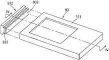
図1は、特許文献1で開示されたフラットパネルディスプレイ水密装置例の背後から見た斜視図である。この図1および図2に示すように、この水密装置91は、フラットパネルディスプレイ92のモニター前方に、周囲を枠で囲んで中央部は空いて窓914になっているフロントフレーム911と、フラットパネルディスプレイ92の後方のバックフレーム913と、フロントフレーム911の窓914の回りに設けられている環状の凹陥部915に嵌めこまれ、且つ、フロントフレーム911とフラットパネルディスプレイ92の間に介在され、その間の隙間を塞ぐ環状のパッキングシート912とからなる。そして、フロントフレーム911とバックフレーム913はねじ916によって堅く係止されている。
FIG. 1 is a perspective view of a flat panel display watertight device disclosed in Patent Document 1 as seen from behind. As shown in FIGS. 1 and 2, the
しかし、特許文献1の水密装置は、取り付け易さ、および、他の装置と接続する利便性の為に、モニター前方の窓914の回りにしか防水機能を設けておらず、後ろ側は完全に開放しているので、フラットパネルディスプレイ92は十分に湿気から隔離されたわけではない。
However, the watertight device of Patent Document 1 is provided with a waterproof function only around the
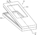
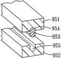
また、図3から図6は特許文献2で開示された水密装置であり、図3,4は特許文献2の第1の実施形態で、図5,6は特許文献2の第2実施形態である。図3,4に示すように、該水密装置93はフラットパネルディスプレイに対応するような形状をなし、一面にだけ開口935が設けられている長方体ケース本体931と、該開口935に対応し、そこからケース本体931内に挿入して開口935を塞ぐことができる突起部938が形成されているキャップ932と、突起部938の回りに巻回され、しかも、開口935の内表面に設けられている凹部936に嵌め込まれるパッキングリング933とからなるものである。そして、図5,6に示す第2の実施形態では、水密装置95は前ケース部951と後ケース部952からなる長方体ケースで、前ケース部951と後ケース部952とのそれぞれの壁部の開口した端面には、それぞれ凹部954と凹部955が設けられ、更に、パッキングリング953が前ケース部951と後ケース部952それぞれの凹部954と凹部955に嵌めこまれて外部の湿気を隔離するものである。
3 to 6 show the watertight device disclosed in
この特許文献2では、パッキングリングを使用する構成によって、該水密装置の防水機能はほぼ万全であるが、その中に収容されたフラットパネルディスプレイも完全に外部から隔離されるため、他の装置と接続することが殆ど不可能となってしまい、実用性もかなり損なわれる。
In this
このように、従来のフラットパネルディスプレイ用水密装置は、防水性と、利用上の利便性とのいずれを選ぶか、時に迷わせるという問題点が発生し、実用可能な水密装置は未だに開発されていない。 As described above, the conventional water-tight device for flat panel displays has a problem that it is sometimes unclear whether to choose between waterproofness or convenience in use, and a practical water-tight device has not yet been developed. Absent.
本発明は、従来の問題を解消するためになされたものであり、防水性と利用上の利便性が両立するフラットパネルディスプレイ用水密装置を提供することを課題とする。 The present invention has been made to solve the conventional problems, and it is an object of the present invention to provide a watertight device for a flat panel display that is compatible with waterproofness and convenience in use.
前記課題を解決するため、本発明は第1に、プレート部と、該プレート部の一面の周縁に沿って突設されているフェンス部とを有する2つのケース体を備え、それぞれのフェンス部が互いに向き合うように組み合わされてフラットパネルディスプレイを収容できる収容空間を形成してなるフラットパネルディスプレイ用水密装置であって、前記2つのケース体の各フェンス部は、その端面が互いに相欠き接合するための段状にされた第1と第2の相欠き部を有し、前記第2の相欠き部が前記第1の相欠き部の内側に嵌入できるように互いに対応しあい、更に、前記第1と第2の相欠き部の互いに向き合っている側面に互いに向き合って対応する環状溝が設けられ、防水のためのパッキングリングが前記第1と第2の相欠き部の環状溝に嵌め込まれていることを特徴とするフラットパネルディスプレイ用水密装置を提供する。 In order to solve the above problems, the present invention firstly includes two case bodies each having a plate portion and a fence portion protruding along the peripheral edge of one surface of the plate portion, and each fence portion has A flat panel display watertight device that is combined so as to face each other to form a housing space that can accommodate a flat panel display, and the fence portions of the two case bodies are joined together with end faces thereof. The first and second phased portions are stepped and correspond to each other so that the second phased portion can be fitted inside the first phased portion. And a corresponding annular groove is provided on the side surfaces of the first and second phased portions facing each other, and a waterproof packing ring is fitted into the annular groove of the first and second phased portions. It is to provide a watertight unit for a flat panel display, characterized in that.
また、本発明は第2に、プレート部と、該プレート部の一面の周縁に沿って突設されているフェンス部とを有する2つのケース体を備え、それぞれのフェンス部が向き合うように、パッキングリングを挟んで組み合わされてフラットパネルディスプレイを収容できる収容空間を形成してなるフラットパネルディスプレイ用水密装置であって、前記2つのケース体のいずれかのプレート部に、前記収容空間と外部とを連通させる開口を設け、前記収容空間内に前記フラットパネルディスプレイと電気的に接続して信号や電力を該フラットパネルディスプレイに転送するアダプタを配設し、該アダプタに前記開口を経由して外部まで延伸するコードユニットを電気的に接続し、前記コードユニットと前記開口の間に隙間を塞ぐ補填手段を配設したことを特徴とするフラットパネルディスプレイ用水密装置をも提供する。 In addition, the present invention secondly includes two case bodies each having a plate portion and a fence portion protruding along a peripheral edge of one surface of the plate portion, and packing is performed so that the respective fence portions face each other. A flat panel display watertight device that is combined with a ring to form a storage space that can store a flat panel display, wherein the storage space and the outside are connected to one of the plate portions of the two case bodies. An opening for communication is provided, and an adapter that is electrically connected to the flat panel display and transfers signals and power to the flat panel display is disposed in the accommodation space, and the adapter is connected to the outside through the opening. The extending cord unit is electrically connected, and a compensating means for closing a gap is provided between the cord unit and the opening. Also to provide a watertight unit for flat panel displays characterized by and.
また、本発明の第1のフラットパネルディスプレイ用水密装置において、前記パッキングリングは、前記第1と第2の相欠き部の環状溝外に張り出して前記第1と第2の相欠き部により圧縮される張り出し部を備えることが好ましい。 Further, in the first flat panel display watertight device of the present invention, the packing ring protrudes outside the annular groove of the first and second phase cutout portions and is compressed by the first and second phase cutout portions. It is preferable to provide an overhanging portion.
また、本発明の各フラットパネルディスプレイ用水密装置において、前記2つのケース体のいずれかの一方のプレート部には、雌ねじを有する管状の第1のステー部が突設され、他方のケース体のプレート部には、スリーブ状をなして前記第1のステー部をその内部に嵌挿させることができる第2のステー部が突設され、前記雌ねじに対応するボルトが、外部から前記第2のステー部に挿入され、対向側から前記第2のステー部に挿入した第1のステー部の雌ねじと締め付けて前記2つのケース体を結合させることが好ましい。 In the watertight device for each flat panel display according to the present invention, a tubular first stay portion having a female screw protrudes from one of the two case bodies, and the other case body The plate portion is provided with a second stay portion that has a sleeve shape and allows the first stay portion to be fitted therein, and a bolt corresponding to the female screw is externally connected to the second stay portion. It is preferable that the two case bodies are joined by being tightened with the female screw of the first stay portion inserted into the stay portion and inserted into the second stay portion from the opposite side.
また、本発明の各フラットパネルディスプレイ用水密装置において、前記2つのケース体は透明材料により形成されることが好ましい。 In the watertight device for each flat panel display according to the present invention, the two case bodies are preferably formed of a transparent material.
また、本発明のフラットパネルディスプレイ用水密装置において、前記パッキングリングは弾性素材により形成されることが好ましい。 In the watertight device for a flat panel display according to the present invention, the packing ring is preferably formed of an elastic material.
また、本発明の各フラットパネルディスプレイ用水密装置において、前記2つのケース体のいずれかのプレート部に、壁掛け手段が取り付けていることが好ましい。
この場合、前記壁掛け手段は、前記2つのケース体のいずれかに取り付けられる板状の取り付け部と、該取り付け部を壁に掛けるように形成されたフック部とを備えることが好ましい。
In the watertight device for each flat panel display of the present invention, it is preferable that a wall hanging means is attached to one of the plate portions of the two case bodies.
In this case, it is preferable that the wall hanging means includes a plate-like attachment portion attached to one of the two case bodies and a hook portion formed so as to hang the attachment portion on the wall.
また、本発明の第2のフラットパネルディスプレイ用水密装置において、前記アダプタと前記フラットパネルディスプレイは、前記アダプタに設けられている端子により直接接続されていることが好ましい。 In the second flat panel display watertight device of the present invention, it is preferable that the adapter and the flat panel display are directly connected by a terminal provided on the adapter.
また、前記アダプタと前記フラットパネルディスプレイは、接続コードを介して接続されているように構成することもできる。 The adapter and the flat panel display may be configured to be connected via a connection cord.
また、前記アダプタと前記フラットパネルディスプレイとの信号転送に用いる転送インターフェイスは、RCAオーディオ端子、同軸ケーブル端子、Sビデオ端子、VGA端子、S端子、RCAビデオ端子、14ピンD端子、15ピンD端子、Y/Pb/Prコンポーネント信号端子、Y/Cb/Crコンポーネント信号端子、DVI端子、HDMI端子、SCART端子などのいずれかを用いることができる。 The transfer interface used for signal transfer between the adapter and the flat panel display includes an RCA audio terminal, a coaxial cable terminal, an S video terminal, a VGA terminal, an S terminal, an RCA video terminal, a 14-pin D terminal, and a 15-pin D terminal. , Y / Pb / Pr component signal terminal, Y / Cb / Cr component signal terminal, DVI terminal, HDMI terminal, SCART terminal, etc. can be used.
上記構成によれば、本発明はフラットパネルディスプレイを効果的に湿気から隔離すると共に、他の装置との良好な接続性を具備させることができるので、従来の水密装置より優れたものを提供することができる。 According to the above configuration, the present invention effectively isolates the flat panel display from moisture and can be provided with good connectivity with other devices, thus providing a superior to conventional watertight devices. be able to.
以下、本発明の実施の形態を図面に従って説明する。 Hereinafter, embodiments of the present invention will be described with reference to the drawings.
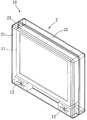
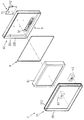
図7から図11は本発明のフラットパネルディスプレイ用水密装置である。図7は該水密装置の外観を示す斜面図であり、図8はその構成を示す分解斜面図であり、図9及び図10はその結合及び水密構造を示す縦断面図であり、図11は外部機械と接続するアダプタとその水密構造を示す横断面図である。また、図12及び図13は前記結合及び水密構造の変化例を示す縦断面図で、図14は外部機械と接続するアダプタとその水密構造の変化例を示す横断面図である。 7 to 11 show a watertight device for a flat panel display according to the present invention. FIG. 7 is a perspective view showing the appearance of the watertight device, FIG. 8 is an exploded perspective view showing the configuration, FIGS. 9 and 10 are longitudinal sectional views showing the coupling and watertight structure, and FIG. It is a cross-sectional view which shows the adapter connected with an external machine, and its watertight structure. 12 and 13 are longitudinal sectional views showing examples of changes in the coupling and watertight structure, and FIG. 14 is a transverse sectional view showing an adapter connected to an external machine and a change example of the watertight structure.
まず、図7および図8を参照しながら本発明の概略的な構成について説明する。図7に示すように、本発明の実施形態に係る水密装置10は、例えばガラスやアグリルなどの透明材料により形成された第1と第2のケース体21,22が組み合ってなるケースユニット2を備え、その内部に形成された収容空間23内にはフラットパネルディスプレイ11と2つのスピーカ12を収容することができる。
First, a schematic configuration of the present invention will be described with reference to FIGS. As shown in FIG. 7, the
また、図8に示すように、水密装置10は、第1と第2のケース体21,22からなるケースユニット2と、第1と第2のケース体21,22の間に介在し、ゴムなどの弾性素材により形成されたパッキングリング3と、第2のケース体22の内表面に配置されているフラットパネルディスプレイ11と接続するためのアダプタ5と、第2のケース体22の外表面に取り付けられる壁掛け手段7とを備えている。
Further, as shown in FIG. 8, the
第1のケース体21は、第1のプレート部211と、該第1のプレート部211の内表面、即ち第2のケース体22を臨む一面の周縁に沿って突設されている第1のフェンス部212と、第1のフェンス部212の先端の外周縁に沿って突設されて第2のケース体と相欠き接合するために段状に形成された第1の相欠き部216とを備えている。第2のケース体22は、第2のプレート部221と、該第2のプレート部221の内表面、即ち第1のケース体21を臨む一面の周縁に沿って突設されている第2のフェンス部222と、第1の相欠き部216に対応し、第2のフェンス部222の先端の内周縁に沿って突設されて段状に形成された第2の相欠き部226とを備えている。そして、第1のケース体21と第2のケース体22とが結合してケースユニット2を構成できるように、2つの相欠き部216、226は、第2の相欠き部226が第1の相欠き部216の内側にぴったり(隙間なく)と嵌入できるように形成されている。
The
壁掛け手段7は、第2のケース体22の外表面に取り付けられる板状の取り付け部71と、該取り付け部71を壁に掛けるように、取り付け部71から突出したフック部72とを備えている。
The wall hanging means 7 includes a plate-
次に、図9及び図10を参照してケース体21,22の結合及び水密構造について説明する。
Next, the coupling of the
第1と第2の相欠き部216、226のそれぞれの向き合っている側面には、互いに向き合って対応する環状溝215と環状溝225とが設けられている。そして、前記2つのケース体21,22の間に介設するパッキングリング3は、2つの環状溝215、225に同時に嵌め込むように配置されている。パッキングリング3の構成について詳しく説明すると、図8に示すように、パッキングリング3は2つの環状溝215、225に対応して全体がリング状に形成されている。そして、図9に示すように、半円形の断面をなし、環状溝215に嵌めこめる第1の突起部32と、同じく半円形の断面をし、環状溝225に嵌めこめる第2の突起部33と、2つの突起部32、33の間に位置してそれらを繋ぐ繋ぎ部31とが形成されている。この構成によって、湿気が外部からケースユニット2の収容空間23内に進入するためには、互いに対応して形成された第1と第2の相欠き部216、226が構成する段差構造と、2つの相欠き部216、226の間に介在するパッキングリング3とを越えねばならず、よって、収容空間23から湿気の隔離はほぼ万全である。
An
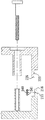
また、2つのケース体21,22をきつく(強固に)結合することでもその防水性を高めることができる。そのため、本発明は、図9,10に示すように、第1のケース体21の第1のプレート部211に対して垂直に突設され、第2のプレート部221に向けて開口し、管状をなしてその内表面に雌ねじ412を有する第1のステー部41と、第2のケース体22の第2のプレート部221に対して垂直に突設され、第1のステー部41をその内部に嵌挿させることができるスリーブ状をなす第2のステー部42とを設ける。そして、第2のステー部42の先端の表面に、前記雌ねじ412に対応する雄ねじ433が形成されているボルト43を、ケースユニット2の外から第2のステー部42の通孔421へ挿入して、図10に示すように第2のステー部42に挿入している第1のステー部41の内表面に設けられている雌ねじ412に対して締め付けて、2つのケース体21,22をきつく結合させることが好ましい。
Moreover, the waterproofness can also be enhanced by tightly (strongly) coupling the two
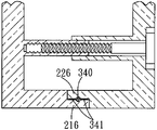
ここで、2つの相欠き部216,226の間に介在されるパッキングリングは、図12,13に示すように構成することもできる。図12に示すように、パッキングリング34は、第1と第2の相欠き部216、226に形成された2つの環状溝215、225に同時に嵌めこむリング本体340に、リング本体340から両側へ張り出して、図13に示すように、2つのケース体21,22が結合すると2つの相欠き部216、226により押し潰される2つの張り出し部341を設けてなったものである。この構成によって、2つの相欠き部216、226により押し潰される2つの張り出し部341は2つの相欠き部216、226に密着するように張り付くので、湿気を隔離する防水性をいっそう高めることができる。
Here, the packing ring interposed between the two
次に、図8とあわせて図11と図14をも参照し、ケースユニット2内に収容されるフラットパネルディスプレイ11を外部機械と接続するアダプタ及びその水密構造、そして変化例について説明する。
Next, an adapter for connecting the
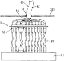
図8に示すように、第2のケース体22の内表面に配置されているアダプタ5は、そのフラットパネルディスプレイ11を臨む一面に、フラットパネルディスプレイ11と接続するために、それぞれ種類が違う接続インターフェイスに対応する複数の接続端子52が設けられている。各接続端子52が対応する転送インターフェイスは、例えばRCAオーディオ端子、同軸ケーブル端子、Sビデオ端子、VGA端子、S端子、RCAビデオ端子、14ピンD端子、15ピンD端子、Y/Pb/Prコンポーネント信号端子、Y/Cb/Crコンポーネント信号端子、DVI端子、HDMI端子、SCART端子などのいずれかとすることが可能である。
As shown in FIG. 8, the
アダプタ5の外部機械との接続は、図11に示すように、各接続端子52にそれぞれ電気的に接続する複数本の電気コード81が、チューブ状の保持手段82によりまとめられて一本のコードユニット80となって、第2のケース体22に設けられている開口228を通って外部機械と接続する。そして、保持手段82と開口228との間の隙間は、ゴムなどの弾性素材により形成された補填手段6により塞がられている。
As shown in FIG. 11, the
また、図11に示すアダプタ5は、各接続端子52により直接的にフラットパネルディスプレイ11と接続しているが、フラットパネルディスプレイはメーカーによって接続する端子の種類や配置が違う可能性が高いので、図14に示すように、接続コード83を利用して、各接続端子52とフラットパネルディスプレイ11を接続して信号の転送を行うこともできる。
Moreover, although the
以上のように、本発明はフラットパネルディスプレイ11をケースユニット2の収容空間23内を隔離するうえ、フラットパネルディスプレイ11と外部機械を繋ぐコードユニット80とアダプタ5とを設けるので、バスルームやプールサイドなど、湿気が多い場所でもフラットパネルディスプレイ11を好適に利用することができる防水性と利用上の利便性を両立したフラットパネルディスプレイ用水密装置を提供することができる。
As described above, the present invention isolates the
10…水密装置
11…フラットパネルディスプレイ
12…スピーカ
2…ケースユニット
21…第1のケース体
211…第1のプレート部
212…第1のフェンス部
215,225…環状溝
216…第1の相欠き部
22…第2のケース体
221…第2のプレート部
222…第2のフェンス部
226…第2の相欠き部
228…開口
23…収容空間
3,34…パッキングリング
31…繋ぎ部
32…第1の突起部
33…第2の突起部
340…リング本体
341…張り出し部
41…第1のステー部
412…雌ねじ
42…第2のステー部
421…通孔
43…ボルト
433…雄ねじ
5…アダプタ
52…接続端子
6…補填手段
7…壁掛け手段
71…取り付け部
72…フック部
80…コードユニット
81…電気コード
82…保持手段
83…接続コード
DESCRIPTION OF
Claims (11)
前記2つのケース体の各フェンス部は、その端面が互いに相欠き接合するための段状にされた第1と第2の相欠き部を有し、前記第2の相欠き部が前記第1の相欠き部の内側に嵌入できるように互いに対応しあい、更に、前記第1と第2の相欠き部の互いに向き合っている側面に互いに向き合って対応する環状溝が設けられ、防水のためのパッキングリングが前記第1と第2の相欠き部の環状溝に嵌め込まれていることを特徴とするフラットパネルディスプレイ用水密装置。 A housing that includes two case bodies each having a plate portion and a fence portion that protrudes along the peripheral edge of one surface of the plate portion, and can accommodate a flat panel display by combining the respective fence portions so as to face each other. A watertight device for a flat panel display formed by forming a space,
Each of the fence portions of the two case bodies has first and second phased portions whose end surfaces are stepped for mutual phase joining, and the second phased portion is the first phased portion. Packing for waterproofing is provided so as to correspond to each other so that they can be fitted inside the phased portions of the first and second phased portions, and corresponding annular grooves are provided to face each other on the mutually facing side surfaces of the first and second phased portions. A watertight device for a flat panel display, characterized in that a ring is fitted in the annular groove of the first and second phase-out portions.
前記2つのケース体のいずれかのプレート部に、前記収容空間と外部とを連通させる開口を設け、前記収容空間内に前記フラットパネルディスプレイと電気的に接続して信号や電力を該フラットパネルディスプレイに転送するアダプタを配設し、該アダプタに前記開口を経由して外部まで延伸するコードユニットを電気的に接続し、前記コードユニットと前記開口の間に隙間を塞ぐ補填手段を配設したことを特徴とするフラットパネルディスプレイ用水密装置。 A flat panel comprising two case bodies having a plate portion and a fence portion protruding along the peripheral edge of one surface of the plate portion, and being combined with a packing ring so that the respective fence portions face each other A watertight device for a flat panel display formed by forming an accommodation space capable of accommodating a display,
An opening for communicating the accommodation space and the outside is provided in one of the plate portions of the two case bodies, and the flat panel display is electrically connected to the flat panel display in the accommodation space to transmit signals and electric power. An adapter that transfers to the adapter, and a cord unit that extends to the outside via the opening is electrically connected to the adapter, and a filling means that closes a gap between the cord unit and the opening is disposed. A watertight device for flat panel displays.
RCAオーディオ端子、同軸ケーブル端子、Sビデオ端子、VGA端子、S端子、RCAビデオ端子、14ピンD端子、15ピンD端子、Y/Pb/Prコンポーネント信号端子、Y/Cb/Crコンポーネント信号端子、DVI端子、HDMI端子、SCART端子などのいずれかを用いることを特徴とする請求項2に記載のフラットパネルディスプレイ用水密装置。 The transfer interface used for signal transfer between the adapter and the flat panel display is:
RCA audio terminal, coaxial cable terminal, S video terminal, VGA terminal, S terminal, RCA video terminal, 14 pin D terminal, 15 pin D terminal, Y / Pb / Pr component signal terminal, Y / Cb / Cr component signal terminal, The watertight device for a flat panel display according to claim 2, wherein any one of a DVI terminal, an HDMI terminal, a SCART terminal, or the like is used.
Applications Claiming Priority (1)
| Application Number | Priority Date | Filing Date | Title |
|---|---|---|---|
| TW095138560A TW200819878A (en) | 2006-10-19 | 2006-10-19 | sealing mechanism of flat panel display |
Publications (1)
| Publication Number | Publication Date |
|---|---|
| JP2008102476A true JP2008102476A (en) | 2008-05-01 |
Family
ID=39317673
Family Applications (1)
| Application Number | Title | Priority Date | Filing Date |
|---|---|---|---|
| JP2007017561A Pending JP2008102476A (en) | 2006-10-19 | 2007-01-29 | Waterproof casing for flat panel display |
Country Status (3)
| Country | Link |
|---|---|
| US (1) | US7733642B2 (en) |
| JP (1) | JP2008102476A (en) |
| TW (1) | TW200819878A (en) |
Cited By (2)
| Publication number | Priority date | Publication date | Assignee | Title |
|---|---|---|---|---|
| KR101081546B1 (en) | 2011-07-25 | 2011-11-08 | 주식회사 이디비젼 | A case for display device with improved waterproof proprety |
| JP2017211669A (en) * | 2017-08-23 | 2017-11-30 | Necプラットフォームズ株式会社 | Display with touch panel, and pos terminal |
Families Citing this family (77)
| Publication number | Priority date | Publication date | Assignee | Title |
|---|---|---|---|---|
| US7969730B1 (en) | 2008-02-08 | 2011-06-28 | Motion Computer, Inc. | Portable computer with thermal control and power source shield |
| US7821782B2 (en) * | 2008-02-08 | 2010-10-26 | Motion Computing, Inc. | Ergonomic solvent resistant portable computer |
| US8152071B2 (en) * | 2008-02-08 | 2012-04-10 | Motion Computing, Inc. | Multi-purpose portable computer with integrated devices |
| JP5213816B2 (en) * | 2008-09-04 | 2013-06-19 | パナソニック株式会社 | Lid opening / closing device and information processing device including the same |
| JP5241414B2 (en) * | 2008-09-30 | 2013-07-17 | 三洋電機株式会社 | Image display device |
| WO2010078321A1 (en) | 2008-12-29 | 2010-07-08 | Otter Products, Llc | Protective cushion cover for an electronic device |
| CN101825783A (en) * | 2009-03-06 | 2010-09-08 | 鸿富锦精密工业(深圳)有限公司 | Thin type electronic device |
| CN201421531Y (en) * | 2009-03-09 | 2010-03-10 | 鸿富锦精密工业(深圳)有限公司 | Transparent electronic installation |
| US20100270190A1 (en) * | 2009-04-22 | 2010-10-28 | Howard David B | Case for a Flat Screen Television |
| US20110017634A1 (en) * | 2009-07-21 | 2011-01-27 | Sweeney Pactick J | Protective cover for electronic books and electronic media devices |
| CN101968670A (en) * | 2009-07-27 | 2011-02-09 | 鸿富锦精密工业(深圳)有限公司 | All-in-one computer |
| US8965458B2 (en) | 2009-08-21 | 2015-02-24 | Otter Products, Llc | Protective cushion cover for an electronic device |
| KR101710647B1 (en) * | 2009-08-25 | 2017-02-27 | 삼성전자 주식회사 | Display apparatus and portable computer having the same |
| WO2011074682A1 (en) * | 2009-12-17 | 2011-06-23 | 日本電気株式会社 | Housing, electronic apparatus, and method for containing display panel |
| US8081267B2 (en) * | 2010-03-08 | 2011-12-20 | Peerless Industries, Inc. | Display enclosure |
| US9025317B2 (en) | 2010-03-17 | 2015-05-05 | Otter Products, Llc | Multi-material protective case for sliding/articulating/rotating handheld electronic devices |
| US8264837B2 (en) * | 2010-04-19 | 2012-09-11 | Apple Inc. | Systems and methods for cover assembly retention of a portable electronic device |
| CN201814042U (en) * | 2010-08-04 | 2011-05-04 | 刘青平 | Protective sleeve |
| US9549598B2 (en) | 2010-10-12 | 2017-01-24 | Treefrog Developments, Inc. | Housing for encasing an electronic device |
| NZ609842A (en) | 2010-10-12 | 2015-01-30 | Tree Frog Developments Inc | Housing for encasing an electronic device |
| USD643433S1 (en) * | 2010-10-14 | 2011-08-16 | Cheng Uei Precision Industry Co., Ltd. | Sleeve for tablet PC |
| US8699220B2 (en) | 2010-10-22 | 2014-04-15 | Xplore Technologies Corp. | Computer with removable cartridge |
| US8830662B2 (en) * | 2011-03-01 | 2014-09-09 | Apple Inc. | Electronic devices with moisture resistant openings |
| CA2838333C (en) * | 2011-06-13 | 2021-07-20 | Treefrog Developments, Inc. | Housing for encasing a tablet computer |
| US9615476B2 (en) | 2011-06-13 | 2017-04-04 | Treefrog Developments, Inc. | Housing for encasing a mobile device |
| USD736777S1 (en) | 2012-06-13 | 2015-08-18 | Treefrog Developments, Inc. | Case for an electronic device |
| JP2013003487A (en) * | 2011-06-21 | 2013-01-07 | Panasonic Liquid Crystal Display Co Ltd | Display device |
| US9158340B2 (en) * | 2011-06-27 | 2015-10-13 | Hand Held Products, Inc. | Apparatus and method for assembling display of indicia reading terminal |
| CN102858102A (en) * | 2011-06-28 | 2013-01-02 | 鸿富锦精密工业(深圳)有限公司 | Electronic equipment shell and manufacturing method thereof |
| USD691990S1 (en) | 2011-08-09 | 2013-10-22 | Treefrog Developments, Inc. | Case for an electronic device |
| USD670280S1 (en) | 2011-08-09 | 2012-11-06 | Treefrog Developments, Inc. | Case for an electronic device |
| USD693801S1 (en) | 2011-08-09 | 2013-11-19 | Treefrog Developments, Inc. | Case for an electronic device |
| USD694227S1 (en) | 2011-08-09 | 2013-11-26 | Treefrog Developments, Inc. | Case for an electronic device |
| USD714769S1 (en) | 2011-10-12 | 2014-10-07 | Treefrog Developments, Inc. | Case for an electronic device |
| US8619417B1 (en) * | 2011-11-08 | 2013-12-31 | The United States Of America As Represented By The Secretary Of The Navy | Water-resistant computer docking station |
| CN103124477A (en) * | 2011-11-21 | 2013-05-29 | 深圳富泰宏精密工业有限公司 | Multifunctional protective casing |
| US20130162120A1 (en) * | 2011-12-27 | 2013-06-27 | Ciil Technologies, Llc | Outdoor Television Display System |
| US10457441B2 (en) | 2012-01-05 | 2019-10-29 | Portero Holdings, Llc | Case for a communication device |
| US9078345B2 (en) * | 2012-01-20 | 2015-07-07 | Ciil Technologies, Llc | Enclosed television with improved cable cover sealing mechanism |
| US8403136B1 (en) * | 2012-04-16 | 2013-03-26 | Aaeon Technology Inc. | Waterproof, shockproof container for handheld electronic device |
| US8876079B2 (en) * | 2012-05-30 | 2014-11-04 | Ncr Corporation | Display location |
| US9469469B2 (en) | 2012-06-01 | 2016-10-18 | Treefrog Developments, Inc. | Housing for encasing an object having a thin profile |
| US8867198B2 (en) * | 2012-06-04 | 2014-10-21 | William Steele | Protective case for a tablet computer |
| GB2500943B (en) * | 2012-06-07 | 2014-06-18 | Paramount Medical Solutions Ltd | Sterile enclosure for an electronic device |
| US9241551B2 (en) | 2012-06-13 | 2016-01-26 | Otter Products, Llc | Protective case with compartment |
| US9039105B2 (en) | 2012-09-05 | 2015-05-26 | Joseph Nick Salvator Divona | Video wall cover |
| US8939289B2 (en) * | 2012-12-14 | 2015-01-27 | Shenzhen China Star Optoelectronics Technology Co., Ltd | Packing box for liquid crystal display panel and waterproof structure thereof |
| CN103876427A (en) * | 2012-12-21 | 2014-06-25 | 富泰华工业(深圳)有限公司 | Waterproof protection sleeve |
| US10136203B2 (en) | 2012-12-28 | 2018-11-20 | Saturn Licensing Llc | Display device |
| US20150201723A1 (en) * | 2013-02-01 | 2015-07-23 | Treefrog Developments, Inc. | Encasements for an electronic device having a biometric scanner |
| US9423671B2 (en) * | 2013-02-14 | 2016-08-23 | Olloclip, Llc | Accessories for communication devices |
| WO2014189807A2 (en) | 2013-05-18 | 2014-11-27 | Otter Products, Llc | Waterproof protective case for an electronic device |
| CN205959622U (en) * | 2013-06-20 | 2017-02-15 | 雨盒子有限责任公司 | A canning for visual display unit |
| US9300078B2 (en) | 2013-08-23 | 2016-03-29 | Otter Products, Llc | Waterproof housing for mobile electronic device and waterproof adapter for accessory device |
| US9726919B2 (en) | 2013-09-17 | 2017-08-08 | Black Diamond Video, Inc. | Water resistant operating room display |
| WO2015105894A1 (en) | 2014-01-07 | 2015-07-16 | Catalyst Lifestyle Limited | Waterproof case |
| US9577697B2 (en) | 2015-05-27 | 2017-02-21 | Otter Products, Llc | Protective case with stylus access feature |
| CN104916229A (en) * | 2015-05-28 | 2015-09-16 | 常州泰勒维克今创电子有限公司 | Waterproof display screen for high-speed rail train toilet |
| US9541961B1 (en) * | 2015-08-25 | 2017-01-10 | Microsoft Technology Licensing, Llc | Shielding via display chassis |
| US9960521B2 (en) | 2016-02-24 | 2018-05-01 | Otter Products, Llc | Connector for fluidly sealing an aperture of a protective case |
| US9844157B1 (en) * | 2016-06-14 | 2017-12-12 | Apple Inc. | Gasket for an electronic device |
| US10159320B2 (en) | 2016-09-07 | 2018-12-25 | Otter Products, Llc | Protective enclosure for encasing an electronic device |
| USD912062S1 (en) * | 2017-08-25 | 2021-03-02 | Maria Francisca Jones | Electronic display apparatus with a mount and display |
| US10827809B2 (en) | 2018-04-05 | 2020-11-10 | Otter Products, Llc | Protective case for electronic device |
| USD924863S1 (en) | 2018-09-11 | 2021-07-13 | Catalyst Lifestyle Limited | Phone case |
| USD984425S1 (en) | 2018-09-11 | 2023-04-25 | Catalyst Lifestyle Limited | Mobile phone protection case |
| TWI687148B (en) * | 2018-12-06 | 2020-03-01 | 英業達股份有限公司 | Display module and assembly method thereof |
| USD903685S1 (en) | 2019-03-29 | 2020-12-01 | Catalyst Lifestyle Limited | Electronic case |
| USD958146S1 (en) | 2019-06-20 | 2022-07-19 | Catalyst Lifestyle Limited | Case for electronic device |
| USD933075S1 (en) | 2019-06-26 | 2021-10-12 | Catalyst Lifestyle Limited | Case for a mobile communication device |
| USD974330S1 (en) | 2019-06-26 | 2023-01-03 | Catalyst Lifestyle Limited | Case for electronic device |
| US11076028B2 (en) | 2019-08-30 | 2021-07-27 | Catalyst Lifestyle Limited | Switch assembly for engaging a switch of an electronic device |
| USD931845S1 (en) | 2020-02-11 | 2021-09-28 | Catalyst Lifestyle Limited | Case for electronic communications device |
| USD932479S1 (en) | 2020-02-11 | 2021-10-05 | Catalyst Lifestyle Limited | Case for electronic communications device |
| USD942438S1 (en) | 2020-02-28 | 2022-02-01 | Catalyst Lifestyle Limited | Bumper for electronic communications device |
| USD984449S1 (en) | 2020-02-28 | 2023-04-25 | Catalyst Lifestyle Limited | Case for electronic device |
| USD941297S1 (en) | 2020-02-28 | 2022-01-18 | Catalyst Lifestyle Limited | Bumper for electronic device |
Citations (15)
| Publication number | Priority date | Publication date | Assignee | Title |
|---|---|---|---|---|
| JPS6113008A (en) * | 1984-06-28 | 1986-01-21 | 日本電気ホームエレクトロニクス株式会社 | Mount boss |
| JPH0270483U (en) * | 1988-11-16 | 1990-05-29 | ||
| JPH0317095U (en) * | 1989-06-30 | 1991-02-20 | ||
| JPH04191792A (en) * | 1990-11-27 | 1992-07-10 | Sony Corp | Water proofing device of large-sized image display device for outdoor |
| JPH08121599A (en) * | 1994-10-24 | 1996-05-14 | Shionogi & Co Ltd | Gasket for sanitary piping and its manufacture |
| JPH09164602A (en) * | 1995-12-18 | 1997-06-24 | Kubota Corp | Waterproof case of electronic machinery |
| WO1999028793A1 (en) * | 1997-11-28 | 1999-06-10 | Citizen Watch Co., Ltd. | Timepiece |
| JPH11259011A (en) * | 1998-03-16 | 1999-09-24 | Hitachi Ltd | Thin type display device |
| JP2003152346A (en) * | 2001-11-12 | 2003-05-23 | Shin Etsu Polymer Co Ltd | Gasket, gasket connector for circuit component and connection structure thereof |
| US20030111366A1 (en) * | 2001-12-14 | 2003-06-19 | Enners Ryan S. | Waterproof casing for Hewlettt-Packard Jornada portable personal computer |
| JP3102679U (en) * | 2004-01-07 | 2004-07-15 | 韋柘股▲分▼有限公司 | Headrest-type portable display module with adjustable angle |
| JP2005020403A (en) * | 2003-06-26 | 2005-01-20 | Yamaha Livingtec Corp | Television viewing system for bathroom |
| WO2005023051A2 (en) * | 2003-08-26 | 2005-03-17 | Thomson Licensing | Visual display wall mounting apparatus |
| JP2005268588A (en) * | 2004-03-19 | 2005-09-29 | Nec Corp | Waterproofing method for electronic equipment and unit |
| JP2006275744A (en) * | 2005-03-29 | 2006-10-12 | Seiko Epson Corp | Sealing structure for case body, and timepiece |
Family Cites Families (10)
| Publication number | Priority date | Publication date | Assignee | Title |
|---|---|---|---|---|
| US4298204A (en) * | 1980-01-21 | 1981-11-03 | Black & Decker Inc. | Seal |
| US5583742A (en) * | 1993-12-15 | 1996-12-10 | Alps Electric Co., Ltd. | Computer with protective cover having outwardly projecting cushioning portions |
| US5713466A (en) * | 1994-09-30 | 1998-02-03 | Oi Electric Co., Ltd. | Water-resistant portable receiver case |
| US5812188A (en) * | 1996-07-12 | 1998-09-22 | Adair; Edwin L. | Sterile encapsulated endoscopic video monitor |
| US6396769B1 (en) * | 1999-10-04 | 2002-05-28 | Rany Polany | System for housing a personal S.C.U.B.A diving audio system |
| US7180735B2 (en) * | 2001-11-19 | 2007-02-20 | Otter Products, Llc | Protective enclosure and watertight adapter for an interactive flat-panel controlled device |
| US6646864B2 (en) * | 2001-11-19 | 2003-11-11 | Otter Products, Llc | Protective case for touch screen device |
| US7158376B2 (en) * | 2001-11-19 | 2007-01-02 | Otter Products, Llc | Protective enclosure for an interactive flat-panel controlled device |
| US7464814B2 (en) * | 2005-01-28 | 2008-12-16 | Carnevali Jeffrey D | Dry box with movable protective cover |
| CN100499971C (en) * | 2005-11-04 | 2009-06-10 | 群康科技(深圳)有限公司 | Panel display |
-
2006
- 2006-10-19 TW TW095138560A patent/TW200819878A/en not_active IP Right Cessation
-
2007
- 2007-01-29 JP JP2007017561A patent/JP2008102476A/en active Pending
- 2007-02-08 US US11/704,608 patent/US7733642B2/en not_active Expired - Fee Related
Patent Citations (15)
| Publication number | Priority date | Publication date | Assignee | Title |
|---|---|---|---|---|
| JPS6113008A (en) * | 1984-06-28 | 1986-01-21 | 日本電気ホームエレクトロニクス株式会社 | Mount boss |
| JPH0270483U (en) * | 1988-11-16 | 1990-05-29 | ||
| JPH0317095U (en) * | 1989-06-30 | 1991-02-20 | ||
| JPH04191792A (en) * | 1990-11-27 | 1992-07-10 | Sony Corp | Water proofing device of large-sized image display device for outdoor |
| JPH08121599A (en) * | 1994-10-24 | 1996-05-14 | Shionogi & Co Ltd | Gasket for sanitary piping and its manufacture |
| JPH09164602A (en) * | 1995-12-18 | 1997-06-24 | Kubota Corp | Waterproof case of electronic machinery |
| WO1999028793A1 (en) * | 1997-11-28 | 1999-06-10 | Citizen Watch Co., Ltd. | Timepiece |
| JPH11259011A (en) * | 1998-03-16 | 1999-09-24 | Hitachi Ltd | Thin type display device |
| JP2003152346A (en) * | 2001-11-12 | 2003-05-23 | Shin Etsu Polymer Co Ltd | Gasket, gasket connector for circuit component and connection structure thereof |
| US20030111366A1 (en) * | 2001-12-14 | 2003-06-19 | Enners Ryan S. | Waterproof casing for Hewlettt-Packard Jornada portable personal computer |
| JP2005020403A (en) * | 2003-06-26 | 2005-01-20 | Yamaha Livingtec Corp | Television viewing system for bathroom |
| WO2005023051A2 (en) * | 2003-08-26 | 2005-03-17 | Thomson Licensing | Visual display wall mounting apparatus |
| JP3102679U (en) * | 2004-01-07 | 2004-07-15 | 韋柘股▲分▼有限公司 | Headrest-type portable display module with adjustable angle |
| JP2005268588A (en) * | 2004-03-19 | 2005-09-29 | Nec Corp | Waterproofing method for electronic equipment and unit |
| JP2006275744A (en) * | 2005-03-29 | 2006-10-12 | Seiko Epson Corp | Sealing structure for case body, and timepiece |
Cited By (2)
| Publication number | Priority date | Publication date | Assignee | Title |
|---|---|---|---|---|
| KR101081546B1 (en) | 2011-07-25 | 2011-11-08 | 주식회사 이디비젼 | A case for display device with improved waterproof proprety |
| JP2017211669A (en) * | 2017-08-23 | 2017-11-30 | Necプラットフォームズ株式会社 | Display with touch panel, and pos terminal |
Also Published As
| Publication number | Publication date |
|---|---|
| US7733642B2 (en) | 2010-06-08 |
| US20080094786A1 (en) | 2008-04-24 |
| TWI334053B (en) | 2010-12-01 |
| TW200819878A (en) | 2008-05-01 |
Similar Documents
| Publication | Publication Date | Title |
|---|---|---|
| JP2008102476A (en) | Waterproof casing for flat panel display | |
| US10021486B1 (en) | Portable auxiliary unit for mobile audio player | |
| CN105721636A (en) | Mobile terminal | |
| JP5649753B1 (en) | Modular plug built-in plug assembly and modular connector built-in connector assembly | |
| ATE508504T1 (en) | WALL FEED-THROUGH CLAMP/CONNECTOR WITH WEDGE-SHAPED MOUNTING | |
| TW201620293A (en) | Display device with detachable speaker modules | |
| WO2023279853A1 (en) | Cable assembly and camera | |
| EP3674838B1 (en) | Electronic device | |
| US8908376B2 (en) | Display panel | |
| TWI426665B (en) | Plug | |
| CN201682153U (en) | Intermediate connecting piece for connecting cable with connecting box | |
| JP2006210032A (en) | Optical and electrical composite connector device | |
| CN102340075B (en) | Cable connector | |
| CN101179911B (en) | Sealing mechanism of planar display | |
| CN219497255U (en) | Display device and electronic device | |
| CN217588347U (en) | LED display device | |
| KR100512749B1 (en) | Monitor | |
| CN212485649U (en) | Waterproof structure of electric connector combination | |
| CN218277409U (en) | Mosaic instrument convenient to dismouting | |
| KR101880920B1 (en) | Moving image photographing system for vehicle | |
| JPH09317951A (en) | Seal structure, cable holding member, and equipment using seal structure | |
| KR20110089969A (en) | Socket for banana plug | |
| JP5553497B2 (en) | connector | |
| KR200212518Y1 (en) | Monitor with detachable camera | |
| CN204205210U (en) | A kind of HDMI socket module with soft connection mechanism |
Legal Events
| Date | Code | Title | Description |
|---|---|---|---|
| A977 | Report on retrieval |
Free format text: JAPANESE INTERMEDIATE CODE: A971007 Effective date: 20090428 |
|
| A131 | Notification of reasons for refusal |
Free format text: JAPANESE INTERMEDIATE CODE: A131 Effective date: 20090507 |
|
| A521 | Written amendment |
Free format text: JAPANESE INTERMEDIATE CODE: A523 Effective date: 20090805 |
|
| A131 | Notification of reasons for refusal |
Free format text: JAPANESE INTERMEDIATE CODE: A131 Effective date: 20100713 |
|
| A02 | Decision of refusal |
Free format text: JAPANESE INTERMEDIATE CODE: A02 Effective date: 20101207 |