JP2008102427A - Optical apparatus and imaging apparatus - Google Patents
Optical apparatus and imaging apparatus Download PDFInfo
- Publication number
- JP2008102427A JP2008102427A JP2006286449A JP2006286449A JP2008102427A JP 2008102427 A JP2008102427 A JP 2008102427A JP 2006286449 A JP2006286449 A JP 2006286449A JP 2006286449 A JP2006286449 A JP 2006286449A JP 2008102427 A JP2008102427 A JP 2008102427A
- Authority
- JP
- Japan
- Prior art keywords
- lens
- optical axis
- lens frame
- axis direction
- optical
- Prior art date
- Legal status (The legal status is an assumption and is not a legal conclusion. Google has not performed a legal analysis and makes no representation as to the accuracy of the status listed.)
- Pending
Links
Images


Classifications
-
- G—PHYSICS
- G02—OPTICS
- G02B—OPTICAL ELEMENTS, SYSTEMS OR APPARATUS
- G02B7/00—Mountings, adjusting means, or light-tight connections, for optical elements
- G02B7/02—Mountings, adjusting means, or light-tight connections, for optical elements for lenses
- G02B7/022—Mountings, adjusting means, or light-tight connections, for optical elements for lenses lens and mount having complementary engagement means, e.g. screw/thread
-
- G—PHYSICS
- G02—OPTICS
- G02B—OPTICAL ELEMENTS, SYSTEMS OR APPARATUS
- G02B15/00—Optical objectives with means for varying the magnification
- G02B15/14—Optical objectives with means for varying the magnification by axial movement of one or more lenses or groups of lenses relative to the image plane for continuously varying the equivalent focal length of the objective
- G02B15/142—Optical objectives with means for varying the magnification by axial movement of one or more lenses or groups of lenses relative to the image plane for continuously varying the equivalent focal length of the objective having two groups only
-
- G—PHYSICS
- G02—OPTICS
- G02B—OPTICAL ELEMENTS, SYSTEMS OR APPARATUS
- G02B15/00—Optical objectives with means for varying the magnification
- G02B15/14—Optical objectives with means for varying the magnification by axial movement of one or more lenses or groups of lenses relative to the image plane for continuously varying the equivalent focal length of the objective
- G02B15/143—Optical objectives with means for varying the magnification by axial movement of one or more lenses or groups of lenses relative to the image plane for continuously varying the equivalent focal length of the objective having three groups only
-
- G—PHYSICS
- G02—OPTICS
- G02B—OPTICAL ELEMENTS, SYSTEMS OR APPARATUS
- G02B15/00—Optical objectives with means for varying the magnification
- G02B15/14—Optical objectives with means for varying the magnification by axial movement of one or more lenses or groups of lenses relative to the image plane for continuously varying the equivalent focal length of the objective
- G02B15/145—Optical objectives with means for varying the magnification by axial movement of one or more lenses or groups of lenses relative to the image plane for continuously varying the equivalent focal length of the objective having five groups only
-
- G—PHYSICS
- G02—OPTICS
- G02B—OPTICAL ELEMENTS, SYSTEMS OR APPARATUS
- G02B7/00—Mountings, adjusting means, or light-tight connections, for optical elements
- G02B7/02—Mountings, adjusting means, or light-tight connections, for optical elements for lenses
- G02B7/04—Mountings, adjusting means, or light-tight connections, for optical elements for lenses with mechanism for focusing or varying magnification
- G02B7/10—Mountings, adjusting means, or light-tight connections, for optical elements for lenses with mechanism for focusing or varying magnification by relative axial movement of several lenses, e.g. of varifocal objective lens
- G02B7/102—Mountings, adjusting means, or light-tight connections, for optical elements for lenses with mechanism for focusing or varying magnification by relative axial movement of several lenses, e.g. of varifocal objective lens controlled by a microcomputer
Landscapes
- Physics & Mathematics (AREA)
- General Physics & Mathematics (AREA)
- Optics & Photonics (AREA)
- Engineering & Computer Science (AREA)
- General Engineering & Computer Science (AREA)
- Lens Barrels (AREA)
Abstract
Description
この発明は、光学装置および撮像装置に関する。 The present invention relates to an optical device and an imaging device.
従来、光軸方向に移動可能なレンズを複数備え、各レンズを光軸方向に移動させることで焦点位置を調整するようにした光学装置があった。このような光学装置では、製造上の都合から、移動可能なレンズはそれぞれ別の鏡筒によって保持されており、光学装置の製造に際しては、或るレンズを光軸方向に移動可能に保持する第1の鏡筒と別のレンズを光軸方向に移動可能に保持する第2の鏡筒とを連結するようにしていた。 Conventionally, there has been an optical apparatus that includes a plurality of lenses that can move in the optical axis direction and adjusts the focal position by moving each lens in the optical axis direction. In such an optical device, the movable lens is held by a separate lens barrel for the convenience of manufacturing, and when manufacturing the optical device, a certain lens is held movably in the optical axis direction. One lens barrel is connected to a second lens barrel that holds another lens movably in the optical axis direction.
また、従来、光軸方向に移動可能なレンズを複数備える光学装置には、移動することによってレンズの光軸が正規の光軸からずれることを防止するために、各レンズの移動位置を案内するガイドポールを備えるものがあった。ガイドポールは、たとえば、移動可能なレンズをそれぞれ保持する各鏡筒に設けられていたり、移動可能なレンズをそれぞれ保持する複数の鏡筒の中のいずれか1つの鏡筒に設けられていたりした。 Conventionally, in an optical apparatus having a plurality of lenses that can move in the optical axis direction, the movement position of each lens is guided in order to prevent the optical axis of the lens from deviating from the normal optical axis due to movement. Some had guide poles. For example, the guide pole is provided in each lens barrel that holds a movable lens, or is provided in any one of a plurality of lens barrels that respectively hold a movable lens. .
具体的には、たとえば、光軸方向に延出する棒状部材を鏡筒内に設けるとともにレンズを保持するレンズ保持枠に光軸方向に貫通する孔を設け、棒状部材を孔に挿入した状態でレンズを移動させることで、レンズが移動する際に当該レンズの光軸が正規の光軸からずれることを防止するようにした技術がある(たとえば、下記特許文献1を参照)。 Specifically, for example, a rod-like member extending in the optical axis direction is provided in the lens barrel, and a hole penetrating in the optical axis direction is provided in the lens holding frame that holds the lens, and the rod-like member is inserted into the hole. There is a technique for preventing the optical axis of the lens from deviating from the normal optical axis when the lens is moved by moving the lens (see, for example, Patent Document 1 below).
また、具体的には、たとえば、非撮像時には装置本体内にレンズ鏡筒を収容する撮像装置で、レンズ鏡筒の光軸上とは異なる位置にレンズ鏡筒を退避させる際の、レンズ鏡筒の位置を簡単かつ高精度に調整するようにした技術がある(たとえば、下記特許文献2を参照)。 Further, specifically, for example, when the lens barrel is retracted to a position different from the optical axis of the lens barrel in the imaging apparatus in which the lens barrel is accommodated in the apparatus main body when not imaging, the lens barrel There is a technique for easily and highly accurately adjusting the position of (see, for example, Patent Document 2 below).
しかしながら、上述した従来の光学装置では、移動可能なレンズはそれぞれ別の鏡筒によって保持されていることから、各鏡筒間の組み付け誤差が、各レンズ間の光軸のずれとなり、光学性能が低下するという問題があった。同様に、上述した従来の光学装置の中で、移動可能なレンズをそれぞれ保持する各鏡筒にガイドポールが設けられている光学装置でも、各鏡筒間の組み付け誤差が、各レンズ間の光軸のずれとなり、光学性能が低下するという問題があった。 However, in the conventional optical device described above, the movable lenses are held by different lens barrels, so that an assembly error between the lens barrels results in a shift of the optical axis between the lenses, and the optical performance is reduced. There was a problem of lowering. Similarly, in the conventional optical device described above, even in an optical device in which a guide pole is provided in each barrel that holds a movable lens, the assembly error between the barrels causes the light between the lenses. There was a problem that the optical performance deteriorated due to the deviation of the axis.
また、上述した従来の光学装置の中で、移動可能なレンズをそれぞれ保持する複数の鏡筒の中のいずれか1つの鏡筒にガイドポールが設けられている光学装置では、各レンズの移動に際しての基準を1本のガイドポールに揃えることができるが、各鏡筒間の組み付け誤差が生じると、ガイドポールが設けられていない別の鏡筒によって保持されるレンズの光学性能を確保することができず、光学性能が低下するという問題があった。 Further, in the conventional optical device described above, in the optical device in which a guide pole is provided in any one of a plurality of lens barrels each holding a movable lens, each lens is moved. However, if an assembly error occurs between the lens barrels, the optical performance of the lens held by another lens barrel not provided with the guide poles can be ensured. There was a problem that the optical performance deteriorated.
この発明は、上述した従来技術による問題点を解消するため、光軸方向に移動可能なレンズが複数存在する場合に、高い光学性能を確保することができる光学装置および撮像装置を提供することを目的とする。 The present invention provides an optical device and an imaging device that can ensure high optical performance when there are a plurality of lenses that can move in the optical axis direction in order to eliminate the above-described problems caused by the prior art. Objective.
この発明にかかる光学装置は、光軸方向に移動可能なレンズを複数備える光学装置において、前記光軸方向に延出し、前記レンズの中の任意のレンズと一体に移動するガイド部材と、前記ガイド部材に沿ってスライド可能であり、前記レンズの中の前記任意のレンズとは別のレンズと一体に移動するスライド部と、を備えることを特徴とする。 The optical device according to the present invention is an optical device including a plurality of lenses movable in the optical axis direction, a guide member extending in the optical axis direction and moving integrally with an arbitrary lens in the lens, and the guide And a slide part that is slidable along the member and moves integrally with a lens different from the arbitrary lens in the lens.
この発明によれば、任意のレンズの光軸が光学装置の光軸に揃うように任意のレンズの位置を調整することで、ガイド部材に沿って移動する別のレンズの光軸を光学装置の光軸に揃えることができるので、光軸方向に移動可能なレンズを複数備える光学装置において高い光学性能を確保することができる。 According to the present invention, by adjusting the position of an arbitrary lens so that the optical axis of an arbitrary lens is aligned with the optical axis of the optical device, the optical axis of another lens moving along the guide member can be adjusted. Since they can be aligned with the optical axis, high optical performance can be ensured in an optical device provided with a plurality of lenses movable in the optical axis direction.
また、この発明にかかる光学装置における前記スライド部は、前記別のレンズまたは当該別のレンズを支持する支持部材を前記光軸方向に貫通する孔であり、前記ガイド部材は、前記任意のレンズまたは当該任意のレンズを支持する支持部材に設けられて前記孔に挿入された棒状部材であることを特徴とする。 In the optical device according to the present invention, the slide portion is a hole that penetrates the another lens or a support member that supports the other lens in the optical axis direction, and the guide member is the arbitrary lens or It is a rod-shaped member that is provided on a support member that supports the arbitrary lens and is inserted into the hole.
この発明によれば、簡易な構成によって任意のレンズおよび別のレンズの光軸を光学装置の光軸に揃えることができるので、高い光学性能を確保した光学装置の小型化および組み立て作業の容易化を図ることができる。 According to the present invention, since the optical axis of an arbitrary lens and another lens can be aligned with the optical axis of the optical device with a simple configuration, the optical device that ensures high optical performance can be downsized and the assembly operation can be facilitated. Can be achieved.
また、この発明にかかる光学装置は、前記任意のレンズと前記別のレンズとの間に設けられて、前記光軸上で位置固定された固定レンズを備え、前記ガイド部材は、前記固定レンズまたは当該固定レンズを支持する支持部材を介して前記孔に挿入されていることを特徴とする。 The optical device according to the present invention includes a fixed lens that is provided between the arbitrary lens and the another lens and is fixed on the optical axis, and the guide member includes the fixed lens or It is inserted into the hole through a support member that supports the fixed lens.
この発明によれば、任意のレンズと別のレンズとの間に、位置固定された固定レンズがある場合にも、任意のレンズおよび別のレンズの光軸を光学装置の光軸に揃えることができるので、光学装置におけるレンズの配列順序に左右されることなく、光軸方向に移動可能なレンズを複数備える光学装置において高い光学性能を確保することができる。 According to the present invention, even when there is a fixed lens whose position is fixed between an arbitrary lens and another lens, the optical axis of the arbitrary lens and the other lens can be aligned with the optical axis of the optical device. Therefore, high optical performance can be ensured in an optical device including a plurality of lenses movable in the optical axis direction without being influenced by the lens arrangement order in the optical device.
また、この発明にかかる撮像装置は、上述した光学装置と、前記光学装置を介して入射された光を電気信号に変換する撮像用の光電変換素子を含む撮像機構と、を備えることを特徴とする。 According to another aspect of the present invention, there is provided an imaging apparatus comprising: the above-described optical device; and an imaging mechanism including a photoelectric conversion element for imaging that converts light incident through the optical device into an electrical signal. To do.
この発明によれば、光学装置を介して撮像機構に入射する外光の焦点位置を、光電変換素子の位置に精度よく合わせることができるので、撮像装置の利用者は、鮮明な画像を得ることができる According to the present invention, since the focal position of the external light incident on the imaging mechanism via the optical device can be accurately adjusted to the position of the photoelectric conversion element, the user of the imaging device can obtain a clear image. Can
この発明にかかる光学装置および撮像装置によれば、光軸方向に移動可能なレンズを複数備える光学装置において高い光学性能を確保することができる。 According to the optical device and the imaging device according to the present invention, high optical performance can be ensured in an optical device including a plurality of lenses movable in the optical axis direction.
以下に添付図面を参照して、この発明にかかる光学装置および撮像装置の好適な実施の形態を詳細に説明する。この実施の形態は、この発明にかかる光学装置を実現するズームレンズ装置への適用例を示す。 Exemplary embodiments of an optical apparatus and an imaging apparatus according to the present invention will be explained below in detail with reference to the accompanying drawings. This embodiment shows an application example to a zoom lens device that realizes the optical device according to the present invention.
(実施の形態1)
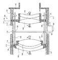
図1は、実施の形態1のズームレンズ装置を示す断面図である。はじめに、図1を用いて、実施の形態1のズームレンズ装置の構成について説明する。図1に示したように、実施の形態1のズームレンズ装置100は、ズームレンズ装置100の光軸方向を軸心方向とする略円筒形状のレンズ鏡筒101を備えている。レンズ鏡筒101は、光軸方向においてレンズ鏡筒101の一端側に設けられたマウント102によって支持されている。
(Embodiment 1)
FIG. 1 is a cross-sectional view illustrating the zoom lens device according to the first embodiment. First, the configuration of the zoom lens apparatus according to the first embodiment will be described with reference to FIG. As shown in FIG. 1, the
ズームレンズ装置100は、たとえば、監視カメラなどに連結して、撮像装置として使用される。図示を省略するが、監視カメラは、入射された外光を電気信号に変換するCCDなどの撮像用の光電変換素子を含む撮像機構を備えている。ズームレンズ装置100は、撮像機構を収容するハウジングとの間に設けられたバヨネット機構あるいはヘリコイド機構などを介して、ハウジングに取り付けられる。この場合、ハウジングの一部によってマウント102が実現される。
The
レンズ鏡筒101の内側には、一連の光軸上に設けられた複数のレンズ103〜106が設けられている。複数のレンズ103〜106のうち、図1中符号103であらわしたレンズ(以下、「L1レンズ」という)、および、図1中符号104であらわしたレンズ(以下、「L2レンズ」という)は、L1/L2レンズ枠107によって保持されている。複数のレンズ103〜106のうち、図1中符号105であらわしたレンズ(以下、「L3レンズ」という)、および、図1中符号106であらわしたレンズ(以下、「L4レンズ」という)は、L3/L4レンズ枠108によって保持されている。
Inside the
レンズ鏡筒101には、L1レンズ103およびL2レンズ104を通過し、L3レンズ105に入射する光量を調整する絞りユニット109が設けられている。公知の技術であるため説明を省略するが、絞りユニット109は、L3レンズ105に入射する光が通過する開口部の径を可変とする絞り羽根を有する絞り羽根機構110と、絞り羽根を駆動して開口部の径を変化させる駆動部111と、を備えている。絞り羽根機構110としては、具体的には、たとえば、光彩絞り羽根などを用いることができる。
The
また、レンズ鏡筒101には、光軸方向を長手方向とする長孔112,113が設けられている。長孔112,113には、それぞれ、長孔112,113内において光軸方向にスライド自在な作動伝達部材114,115が挿入されている。作動伝達部材114は、L1/L2レンズ枠107に取り付けられている。これによって、L1/L2レンズ枠107は、レンズ鏡筒101内において光軸方向に移動可能に設けられている。
In addition, the
レンズ鏡筒101の外周側には、光軸方向を軸心方向とする略円筒形状を有し、光軸周りに回転自在なL1/L2レンズ枠作動リング116およびL3/L4レンズ枠作動リング117が設けられている。L1/L2レンズ枠作動リング116は、長孔112を覆う位置に設けられている。L3/L4レンズ枠作動リング117は、長孔113を覆う位置に設けられている。
On the outer peripheral side of the
L1/L2レンズ枠作動リング116およびL3/L4レンズ枠作動リング117の内周面には、それぞれ、光軸を軸心方向とする螺旋状のカム溝118,119が設けられている。上述した作動伝達部材114,115は、それぞれ、カム溝118,119に係合している。
On the inner peripheral surfaces of the L1 / L2 lens
L1/L2レンズ枠作動リング116が光軸周りに回転すると、カム溝118に係合している作動伝達部材114がL1/L2レンズ枠作動リング116の回転に連られて光軸周りに回転しようとするが、作動伝達部材114は長孔112に挿入されていることから光軸周りに回転はせず、カム溝118に対する係合位置を変えながら光軸方向にのみ移動する。このような作動伝達部材114の動作によって、L1/L2レンズ枠107は、L1/L2レンズ枠作動リング116の回転にともなって、光軸方向にのみ移動する(図1中矢印A,Bを参照)。
When the L1 / L2 lens
L3/L4レンズ枠作動リング117が光軸周りに回転すると、カム溝119に係合している作動伝達部材115がL3/L4レンズ枠作動リング117の回転に連られて光軸周りに回転しようとするが、作動伝達部材115は長孔113に挿入されていることから光軸周りに回転はせず、カム溝119に対する係合位置を変えながら光軸方向にのみ移動する。このような作動伝達部材115の動作によって、L3/L4レンズ枠108は、L3/L4レンズ枠作動リング117の回転にともなって、光軸方向にのみ移動する(図1中矢印C,Dを参照)。
When the L3 / L4 lens
実施の形態1においては、L1/L2レンズ枠107に保持された各レンズ103,104によって任意のレンズが実現されている。また、実施の形態1においては、L3/L4レンズ枠108に保持されたレンズ105,106によって別のレンズが実現されている。
In the first embodiment, an arbitrary lens is realized by the
L1/L2レンズ枠107には、光軸方向に延出するガイド部材としてのガイドポール120が設けられている。ガイドポール120は、光軸方向を長手方向とする棒状部材である。ガイドポール120の一端側はL1/L2レンズ枠107に固定されており、他端側はレンズ鏡筒101の内側に設けられた支持用リブ121に支持されている。支持用リブ121は、レンズ鏡筒101の内周面から光軸方向に向かって突出する板状部材である。
The L1 /
図1中符号を省略するが、支持用リブ121には、支持用リブ121を光軸方向に貫通する受け孔が設けられている。受け孔の径は、ガイドポール120の径と同等またはガイドポール120の径よりも若干大きく設計されている。ガイドポール120は、L1/L2レンズ枠107の移動にともなって、受け孔に対してスライドしながら光軸方向に移動する。
Although omitted in FIG. 1, the
また、図1中符号を省略するが、L3/L4レンズ枠108には、光軸方向に貫通する貫通孔が設けられている。貫通孔の径は、ガイドポール120の径と同等またはガイドポール120の径よりも若干大きく設計されている。貫通孔にはガイドポール120が挿入されており、これによって、L3/L4レンズ枠108はガイドポール120に沿って移動する。上述した絞り羽根機構110には、光軸方向に貫通する孔123が設けられている。ガイドポール120は、孔123を介してL3/L4レンズ枠108側に延出している。実施の形態1においては、L3/L4レンズ枠108に設けられた貫通孔によってスライド部が実現されている。
Further, although the reference numerals in FIG. 1 are omitted, the L3 /
上述したように、実施の形態1のズームレンズ装置100によれば、L1/L2レンズ枠107の位置を調整してL1レンズ103およびL2レンズ104の光軸をズームレンズ装置100の光軸に揃えることで、ガイドポール120に沿って移動するL3/L4レンズ枠108が保持するL3レンズ105およびL4レンズ106の光軸をズームレンズ装置100の光軸に揃えることができる。
As described above, according to the
これによってズームレンズ装置100は、光軸方向に移動可能な複数のレンズ103〜106の光軸をズームレンズ装置100の光軸に揃え、ズームレンズ装置100において高い光学性能を確保することができる。そして、これによってズームレンズ装置100の利用者は、解像度および品質の高い画像を得ることができる。
Accordingly, the
また、実施の形態1のズームレンズ装置100によれば、L3/L4レンズ枠108に設けられた貫通孔にガイドポール120を挿入する、簡易な構成によって複数のレンズ103〜106の光軸をズームレンズ装置100の光軸に揃えることができるので、高い光学性能を確保したズームレンズ装置100の小型化および組み立て作業の容易化を図ることができる。
Further, according to the
また、実施の形態1のズームレンズ装置100を備える監視カメラによれば、ズームレンズ装置100を介してハウジング内に入射する外光の焦点位置を、ハウジング内に設けられたCCDにおける光電変換面に精度よく合わせることができる。これによって、監視カメラは、CCDの画素数が増加した場合にも、高画素化に対応した高い解像度の画像光をCCDに結像することができる。そして、これによってズームレンズ装置100を備える監視カメラの利用者は、鮮明な画像を得ることができる。
Further, according to the surveillance camera including the
(実施の形態2)
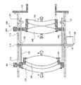
図2は、実施の形態2のズームレンズ装置を示す断面図である。つぎに、図2を用いて、実施の形態2のズームレンズ装置の構成について説明する。実施の形態2においては、上述した実施の形態1と同一部分は同一符号で示し、説明を省略する。実施の形態2のズームレンズ装置は、上述したズームレンズ装置100と同様に、たとえば、CCDを備える監視カメラなどに連結して使用することができる。
(Embodiment 2)
FIG. 2 is a cross-sectional view illustrating the zoom lens device according to the second embodiment. Next, the configuration of the zoom lens apparatus according to Embodiment 2 will be described with reference to FIG. In the second embodiment, the same parts as those in the first embodiment are denoted by the same reference numerals, and the description thereof is omitted. Similarly to the
図2に示したように、実施の形態2のズームレンズ装置200は、作動伝達部材114およびL1/L2レンズ枠作動リング116に代えて設けられたL1/L2レンズ枠操作レバー201と、作動伝達部材115およびL3/L4レンズ枠作動リング117に代えて設けられたL3/L4レンズ枠操作レバー202と、を備えている。L1/L2レンズ枠操作レバー201は、長孔112を介してL1/L2レンズ枠107に取り付けられている。L3/L4レンズ枠操作レバー202は、長孔113を介してL3/L4レンズ枠108に取り付けられている。
As shown in FIG. 2, the
L1/L2レンズ枠107は、ズームレンズ装置200の利用者などの操作によってL1/L2レンズ枠操作レバー201に外力が加えられた場合に、加えられた外力の方向に応じて光軸方向に移動する。L1/L2レンズ枠操作レバー201は長孔112に挿入されていることから光軸周りには移動せず、光軸方向にのみ移動する。このようなL1/L2レンズ枠操作レバー201の動作によって、L1/L2レンズ枠107は、加えられた外力の方向に応じて、光軸方向にのみ移動する(図2中矢印A,Bを参照)。
The L1 /
L3/L4レンズ枠108は、ズームレンズ装置200の利用者などの操作によってL3/L4レンズ枠操作レバー202に外力が加えられた場合に、加えられた外力の方向に応じて光軸方向に移動する。L3/L4レンズ枠操作レバー202は長孔113に挿入されていることから光軸周りには移動せず、光軸方向にのみ移動する。このようなL3/L4レンズ枠操作レバー202の動作によって、L3/L4レンズ枠108は、加えられた外力の方向に応じて、光軸方向にのみ移動する(図2中矢印C,Dを参照)。
The L3 /
上述したように、実施の形態2のズームレンズ装置200によれば、L1/L2レンズ枠操作レバー201やL3/L4レンズ枠操作レバーをズームレンズ装置200の利用者などが直接操作するという簡易な構成によって複数のレンズ103〜106の光軸をズームレンズ装置100の光軸に揃えることができるので、高い光学性能を確保したズームレンズ装置100の小型化および組み立て作業の容易化を図ることができる。
As described above, according to the
これによって、ズームレンズ装置200は、光軸方向に移動可能な複数のレンズ103〜106の光軸をズームレンズ装置200の光軸に揃え易くして、ズームレンズ装置200において一層高い光学性能を確保することができる。そして、これによってズームレンズ装置200の利用者は、解像度および品質の高い画像を得ることができる。
Accordingly, the
また、実施の形態2のズームレンズ装置200を備える監視カメラによれば、ズームレンズ装置200を介してハウジング内に入射する外光の焦点位置を、ハウジング内に設けられたCCDにおける光電変換面に精度よく合わせることができる。これによって、監視カメラは、CCDの画素数が増加した場合にも、高画素化に対応した高い解像度の画像光をCCDに結像することができる。そして、これによってズームレンズ装置200を備える監視カメラの利用者は、鮮明な画像を得ることができる。
Further, according to the surveillance camera including the
(実施の形態3)
図3は、実施の形態3のズームレンズ装置を示す断面図である。つぎに、図3を用いて、実施の形態3のズームレンズ装置の構成について説明する。実施の形態3においては、上述した実施の形態1,2と同一部分は同一符号で示し、説明を省略する。実施の形態3のズームレンズ装置は、上述したズームレンズ装置100,200と同様に、たとえば、CCDを備える監視カメラなどに連結して使用することができる。
(Embodiment 3)
FIG. 3 is a cross-sectional view illustrating the zoom lens apparatus according to the third embodiment. Next, the configuration of the zoom lens apparatus according to Embodiment 3 will be described with reference to FIG. In the third embodiment, the same parts as those in the first and second embodiments are denoted by the same reference numerals, and description thereof is omitted. The zoom lens apparatus according to the third embodiment can be used by being connected to, for example, a monitoring camera including a CCD, similarly to the
図3に示したように、実施の形態3のズームレンズ装置300は、L1/L2レンズ枠作動リング116に代えて設けられたL1/L2レンズ枠駆動用モーターユニット301と、L3/L4レンズ枠作動リング117に代えて設けられたL3/L4レンズ枠駆動用モーターユニット302と、を備えている。
As shown in FIG. 3, the
L1/L2レンズ枠駆動用モーターユニット301は、レンズ鏡筒101の外周側に設けられて、光軸方向を軸心方向とするシャフト303と、シャフト303の軸心周りにシャフト303を回転させる駆動力を発生するモーター304と、を備えている。図3中符号を省略するが、シャフト303の外周面には、ヘリコイド溝が設けられている。また、図3中符号を省略するが、シャフト303の外周面に設けられたヘリコイド溝には、L1/L2レンズ枠107に取り付けられた作動伝達部材114に設けられたヘリコイド溝がかみ合わされている。
The L1 / L2 lens frame driving
L3/L4レンズ枠駆動用モーターユニット302は、レンズ鏡筒101の外周側に設けられて、光軸方向を軸心方向とするシャフト305と、シャフト305の軸心周りにシャフト305を回転させる駆動力を発生するモーター306と、を備えている。図3中符号を省略するが、シャフト305の外周面には、上述したシャフト303と同様に、ヘリコイド溝が設けられている。また、図3中符号を省略するが、シャフト305の外周面に設けられたヘリコイド溝には、L3/L4レンズ枠108に取り付けられた作動伝達部材115に設けられたヘリコイド溝がかみ合わされている。
The L3 / L4 lens frame driving
モーター304の駆動力が伝達されたシャフト303が光軸周りに回転すると、シャフト303の外周面に設けられたヘリコイド溝にかみ合わされている作動伝達部材114がシャフト303の回転に連られて光軸周りに回転しようとするが、作動伝達部材114は長孔112に挿入されていることから光軸周りに回転はせず、シャフト303に対するかみ合い位置を変えながら光軸方向にのみ移動する。このような作動伝達部材114の動作によって、L1/L2レンズ枠107は、シャフト303の回転にともなって、光軸方向にのみ移動する(図3中矢印A,Bを参照)。
When the
モーター306の駆動力が伝達されたシャフト305が光軸周りに回転すると、シャフト305の外周面に設けられたヘリコイド溝にかみ合わされている作動伝達部材115がシャフト305の回転に連られて光軸周りに回転しようとするが、作動伝達部材115は長孔113に挿入されていることから光軸周りに回転はせず、シャフト305に対する係合位置を変えながら光軸方向にのみ移動する。このような作動伝達部材115の動作によって、L3/L4レンズ枠108は、シャフト305の回転にともなって、光軸方向にのみ移動する(図3中矢印C,Dを参照)。
When the
上述したように、実施の形態3のズームレンズ装置300によれば、モーター304やモーター306の駆動力を用いて、L1/L2レンズ枠107やL3/L4レンズ枠108を光軸方向に移動させることで、L1/L2レンズ枠107やL3/L4レンズ枠108の移動量を精度よく微調整することができる。
As described above, according to the
これによって、ズームレンズ装置300は、光軸方向に移動可能な複数のレンズ103〜106の光軸をズームレンズ装置300の光軸に揃え易くして、ズームレンズ装置200において一層高い光学性能を確保することができる。そして、これによってズームレンズ装置200の利用者は、解像度および品質の高い画像を得ることができる。
Accordingly, the
また、実施の形態3のズームレンズ装置300を備える監視カメラによれば、ズームレンズ装置300を介してハウジング内に入射する外光の焦点位置を、ハウジング内に設けられたCCDにおける光電変換面に精度よく合わせることができる。これによって、監視カメラは、CCDの画素数が増加した場合にも、高画素化に対応した高い解像度の画像光をCCDに結像することができる。そして、これによってズームレンズ装置300を備える監視カメラの利用者は、鮮明な画像を得ることができる。
Further, according to the surveillance camera including the
(実施の形態4)
図4は、実施の形態4のズームレンズ装置を示す断面図である。つぎに、図4を用いて、実施の形態4のズームレンズ装置の構成について説明する。実施の形態4においては、上述した実施の形態1〜3と同一部分は同一符号で示し、説明を省略する。実施の形態4のズームレンズ装置は、上述したズームレンズ装置100,200,300と同様に、たとえば、CCDを備える監視カメラなどに連結して使用することができる。
(Embodiment 4)
FIG. 4 is a cross-sectional view showing the zoom lens device according to the fourth embodiment. Next, the configuration of the zoom lens apparatus according to Embodiment 4 will be described with reference to FIG. In the fourth embodiment, the same parts as those in the first to third embodiments are denoted by the same reference numerals, and the description thereof is omitted. The zoom lens apparatus according to the fourth embodiment can be used by being connected to, for example, a monitoring camera including a CCD, similarly to the
図4に示したように、実施の形態4のズームレンズ装置400は、複数のレンズ401〜405を備えている。複数のレンズ401〜405のうち、図4中符号401であらわしたレンズ(以下、「L1レンズ」という)、および、図4中符号402であらわしたレンズ(以下、「L2レンズ」という)は、L1/L2レンズ枠406によって保持されている。複数のレンズ401〜405のうち、図4中符号403であらわしたレンズ(以下、「L3レンズ」という)は、L3レンズ枠407によって保持されている。
As shown in FIG. 4, the
また、複数のレンズ401〜405のうち、図4中符号404であらわしたレンズ(以下、「L4レンズ」という)、および、図4中符号405であらわしたレンズ(以下、「L5レンズ」という)は、L4/L5レンズ枠408によって保持されている。L1/L2レンズ枠406,L3レンズ枠407,およびL4/L5レンズ枠408には、それぞれ、レンズ鏡筒409に設けられた長孔410〜412に挿入された作動伝達部材413〜415が取り付けられており、光軸方向にのみ移動可能に設けられている。
Further, among the plurality of
レンズ鏡筒409の外周側で長孔410〜412に対向する位置には、それぞれ、L1/L2レンズ枠駆動用モーターユニット416,L3レンズ枠駆動用モーターユニット417,およびL4/L5レンズ枠駆動用モーターユニット418が設けられている。図4中符号を省略するが、各レンズ枠駆動用モーターユニット416〜418は、それぞれ、光軸方向を軸心方向とするシャフトと、シャフトをシャフトの光軸回りに回転させる駆動力を発生するモーターと、を備えている。
L1 / L2 lens frame driving
各レンズ枠駆動用モーターユニット416〜418が備えるシャフトの外周面にはヘリコイド溝が設けられており、各シャフトのヘリコイド溝には、それぞれ、作動伝達部材413〜415に設けられたヘリコイド溝がかみ合わされている。これによって、L1/L2レンズ枠406,L3レンズ枠407,およびL4/L5レンズ枠408は、光軸方向にのみ移動する(図4中矢印A〜Fを参照)。
Helicoid grooves are provided on the outer peripheral surfaces of the shafts of the lens frame driving
実施の形態4においては、L3レンズ枠407に保持されたL3レンズ403によって任意のレンズが実現されている。また、実施の形態4においては、L1/L2レンズ枠406およびL4/L5レンズ枠408に保持されたレンズ401,402,404,405によって別のレンズが実現されている。
In the fourth embodiment, an arbitrary lens is realized by the L3 lens 403 held by the
L3レンズ枠407には、光軸方向に延出するガイド部材としてのガイドポール419が設けられている。ガイドポール419は、光軸方向を長手方向とする棒状部材であり、長手方向における中央部分がL3レンズ枠407に固定されている。L4/L5レンズ枠408側となるガイドポール419の端部は、レンズ鏡筒409の内側に設けられた支持用リブ121に支持されている。
The
図4中符号を省略するが、L4/L5レンズ枠408には、光軸方向に貫通し、ガイドポール419が挿入された貫通孔が設けられている。L4/L5レンズ枠408に設けられた貫通孔の径は、ガイドポール419の径と同等またはガイドポール419の径よりも若干大きく設計されている。L4/L5レンズ枠408は、L4/L5レンズ枠駆動用モーターユニット418におけるモーターで発生した駆動力によるシャフトの回転にともなって、ガイドポール419に沿って光軸方向に移動する。
Although not shown in FIG. 4, the L4 /
また、図4中符号を省略するが、L1/L2レンズ枠406側となるガイドポール419の端部は、L1/L2レンズ枠406に設けられて、L1/L2レンズ枠406を光軸方向に貫通する貫通孔に挿入されている。L1/L2レンズ枠406に設けられた貫通孔の径は、ガイドポール419の径と同等またはガイドポール419の径よりも若干大きく設計されている。L1/L2レンズ枠406は、L1/L2レンズ枠駆動用モーターユニット416におけるモーターで発生した駆動力によるシャフトの回転にともなって、ガイドポール419に沿って光軸方向に移動する。
Although not shown in FIG. 4, the end portion of the
ガイドポール419の光軸方向における寸法は、L1/L2レンズ枠406とL3レンズ枠407とが最も離間した場合、L3レンズ枠407とL4/L5レンズ枠408とが最も離間した場合、あるいは、L1/L2レンズ枠406とL4/L5レンズ枠408とが最も離間した場合にも、ガイドポール419がL1/L2レンズ枠406,支持用リブ121,あるいはL4/L5レンズ枠408から抜けてしまうことがない長さに設計されている。実施の形態4においては、L1/L2レンズ枠406およびL4/L5レンズ枠408に設けられた貫通孔によってスライド部が実現されている。
The dimension of the
上述したように、実施の形態4のズームレンズ装置400によれば、L3レンズ枠407の位置を調整してL3レンズ403の光軸をズームレンズ装置400の光軸に揃えることで、ガイドポール419に沿って移動するL1/L2レンズ枠406が保持するL1レンズ401およびL2レンズ402およびとL4/L5レンズ枠408が保持するL4レンズ404およびL5レンズ405の光軸をズームレンズ装置400の光軸に揃えることができる。
As described above, according to the
また、実施の形態4のズームレンズ装置400によれば、ガイドポール419が固定されているL3レンズ枠407と、L3レンズ枠407に固定されたガイドポール419を移動に際する位置の基準とするL1/L2レンズ枠406およびL4/L5レンズ枠408と、が一対一で対応していなくても、ガイドポール419が固定されているL3レンズ枠407の位置を調整するだけで、複数のレンズ枠406,408が保持する複数のレンズ401,402,404,405の光軸をズームレンズ装置400の光軸に揃えることができる。
Further, according to the
また、実施の形態4のズームレンズ装置400を備える監視カメラによれば、ズームレンズ装置400を介してハウジング内に入射する外光の焦点位置を、ハウジング内に設けられたCCDにおける光電変換面に精度よく合わせることができる。これによって、監視カメラは、CCDの画素数が増加した場合にも、高画素化に対応した高い解像度の画像光をCCDに結像することができる。そして、これによってズームレンズ装置400を備える監視カメラの利用者は、鮮明な画像を得ることができる。
Further, according to the surveillance camera including the
(実施の形態5)
図5は、実施の形態5のズームレンズ装置を示す断面図である。つぎに、図5を用いて、実施の形態5のズームレンズ装置の構成について説明する。実施の形態5においては、上述した実施の形態1〜4と同一部分は同一符号で示し、説明を省略する。実施の形態5のズームレンズ装置は、上述したズームレンズ装置100,200,300,400と同様に、たとえば、CCDを備える監視カメラなどに連結して使用することができる。
(Embodiment 5)
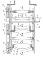
FIG. 5 is a cross-sectional view showing the zoom lens apparatus according to the fifth embodiment. Next, the configuration of the zoom lens apparatus according to Embodiment 5 will be described with reference to FIG. In the fifth embodiment, the same parts as those in the first to fourth embodiments are denoted by the same reference numerals, and description thereof is omitted. The zoom lens device according to the fifth embodiment can be used by being connected to, for example, a monitoring camera equipped with a CCD, similarly to the
図5に示したように、実施の形態5のズームレンズ装置500は、複数のレンズ501〜507を備えている。複数のレンズ501〜507のうち、図5中符号501であらわしたレンズ(以下、「L1レンズ」という)、および、図5中符号502であらわしたレンズ(以下、「L2レンズ」という)は、L1/L2レンズ枠508によって保持されている。複数のレンズ501〜507のうち、図5中符号503であらわしたレンズ(以下、「L3レンズ」という)は、レンズ鏡筒509の内側に設けられたL3レンズ支持部材510によって保持されている。
As shown in FIG. 5, the
また、複数のレンズ501〜507のうち、図5中符号504であらわしたレンズ(以下、「L4レンズ」という)、および、図5中符号505であらわしたレンズ(以下、「L5レンズ」という)は、L4/L5レンズ枠511によって保持されている。複数のレンズ501〜507のうち、図5中符号506であらわしたレンズ(以下、「L6レンズ」という)は、レンズ鏡筒509の内側に設けられたL6レンズ支持部材512によって保持されている。
Among the plurality of
複数のレンズ501〜507のうち、図5中符号507であらわしたレンズ(以下、「L7レンズ」という)は、L7レンズ枠513によって保持されている。L1/L2レンズ枠508,L4/L5レンズ枠511,およびL7レンズ枠513には、それぞれ、レンズ鏡筒509に設けられた長孔514〜516に挿入された作動伝達部材517〜519が取り付けられており、光軸方向にのみ移動可能に設けられている。
Among the plurality of
レンズ鏡筒509の外周側で長孔514〜516に対向する位置には、それぞれ、L1/L2レンズ枠駆動用モーターユニット520,L4/L5レンズ枠駆動用モーターユニット521,およびL7レンズ枠駆動用モーターユニット522が設けられている。図5中符号を省略するが、各レンズ枠駆動用モーターユニット520〜522は、それぞれ、光軸方向を軸心方向とするシャフトと、シャフトをシャフトの光軸回りに回転させる駆動力を発生するモーターと、を備えている。
L1 / L2 lens frame driving
各レンズ枠駆動用モーターユニット520〜522が備えるシャフトの外周面にはヘリコイド溝が設けられており、各シャフトのヘリコイド溝には、それぞれ、作動伝達部材517〜519に設けられたヘリコイド溝がかみ合わされている。これによって、L1/L2レンズ枠508,L4/L5レンズ枠511,およびL7レンズ枠513は、光軸方向にのみ移動する(図5中矢印A〜Fを参照)。
Helicoid grooves are provided on the outer peripheral surfaces of the shafts of the lens frame driving
実施の形態5においては、L4/L5レンズ枠511に保持された各レンズ504,505によって任意のレンズが実現されている。また、実施の形態5においては、L1/L2レンズ枠508およびL7レンズ枠513に保持された各レンズ501,502,507によって別のレンズが実現されている。さらに、実施の形態5においては、L3レンズ支持部材510およびL6レンズ支持部材512によって保持された各レンズ503,506によって固定レンズが実現されている。
In the fifth embodiment, an arbitrary lens is realized by the
L4/L5レンズ枠511には、光軸方向に延出するガイド部材としてのガイドポール523が設けられている。ガイドポール523は、光軸方向を長手方向とする棒状部材であり、長手方向における中央部分がL4/L5レンズ枠511に固定されている。図5中符号を省略するが、L1/L2レンズ枠508およびL7レンズ枠513には、L1/L2レンズ枠508およびL7レンズ枠513を貫通する貫通孔が設けられている。実施の形態5においては、L1/L2レンズ枠508およびL7レンズ枠513に設けられた貫通孔によってスライド部が実現されている。
The L4 /
L4/L5レンズ枠511を間にしてガイドポール523の両端部は、L1/L2レンズ枠508およびL7レンズ枠513に設けられた貫通孔に挿入されており、それぞれ、L1/L2レンズ枠508およびL7レンズ枠513に対してL4/L5レンズ枠511の反対側に突き抜けている。
Both end portions of the
図5中符号を省略するが、L3レンズ支持部材510およびL6レンズ支持部材512には、それぞれ、L3レンズ支持部材510およびL6レンズ支持部材512を光軸方向に貫通する貫通孔が設けられている。ガイドポール523は、L4/L5レンズ枠511における固定位置から、L3レンズ支持部材510およびL6レンズ支持部材512に設けられた貫通孔を介して、L1/L2レンズ枠508およびL7レンズ枠513側へ延出している。
Although not shown in FIG. 5, the L3
L3レンズ支持部材510およびL6レンズ支持部材512に設けられた貫通孔の径は、ガイドポール523の径と同等またはガイドポール523の径よりも若干大きく設計されている。ガイドポール523は、L4/L5レンズ枠駆動用モーターユニット521におけるモーターで発生した駆動力によるシャフトの回転にともなって、L3レンズ支持部材510およびL6レンズ支持部材512に設けられた貫通孔に沿って光軸方向に移動する。
The diameters of the through holes provided in the L3
レンズ鏡筒509の内側であって絞り羽根機構110の近傍には、支持用リブ121が設けられている。ガイドポール523は、支持用リブ121に設けられた孔123に挿入されており、支持用リブ121にスライド自在な状態で支持用リブ121によって支持されている。
A
上述したように、実施の形態5のズームレンズ装置500によれば、L1/L2レンズ枠508とL4/L5レンズ枠511との間に、位置固定されたL3レンズ支持部材510に支持されたL3レンズ503がある場合にも、L1/L2レンズ枠508およびL4/L5レンズ枠511が保持する各レンズ501,502,504,505の光軸をズームレンズ装置500の光軸に揃えることができるので、ズームレンズ装置500における各レンズ501〜507の配列順序に左右されることなく、光軸方向に移動可能なレンズ501,502,504,505を複数備えるズームレンズ装置500における高い光学性能を確保することができる。
As described above, according to the
また、実施の形態5のズームレンズ装置500によれば、L4/L5レンズ枠511とL7レンズ枠513との間に、位置固定されたL6レンズ支持部材512に支持されたL6レンズ506がある場合にも、L4/L5レンズ枠511およびL7レンズ枠513が保持する各レンズ504,505,507の光軸をズームレンズ装置500の光軸に揃えることができるので、ズームレンズ装置500における各レンズ501〜507の配列順序に左右されることなく、光軸方向に移動可能なレンズ504,505,507を複数備えるズームレンズ装置500における高い光学性能を確保することができる。
Further, according to the
以上のように、この発明にかかる光学装置および撮像装置は、光軸方向に移動可能な複数のレンズの光軸を揃えることに適しており、特に、光軸方向に移動可能な複数のレンズを備えるズームレンズ装置などに適している。 As described above, the optical device and the imaging device according to the present invention are suitable for aligning the optical axes of a plurality of lenses that are movable in the optical axis direction, and in particular, a plurality of lenses that are movable in the optical axis direction. It is suitable for a zoom lens device provided.
100 ズームレンズ装置
103,104 任意のレンズ
120 ガイド部材
105,106 別のレンズ
200 ズームレンズ装置
300 ズームレンズ装置
400 ズームレンズ装置
403 任意のレンズ
419 ガイド部材
401,402,404,405 別のレンズ
500 ズームレンズ装置
504,505 任意のレンズ
523 ガイド部材
501,502,507 別のレンズ
503,506 固定レンズ
DESCRIPTION OF
Claims (4)
前記光軸方向に延出し、前記レンズの中の任意のレンズと一体に移動するガイド部材と、
前記ガイド部材に沿ってスライド可能であり、前記レンズの中の前記任意のレンズとは別のレンズと一体に移動するスライド部と、
を備えることを特徴とする光学装置。 In an optical device including a plurality of lenses movable in the optical axis direction,
A guide member extending in the optical axis direction and moving integrally with an arbitrary lens in the lens;
A slide part that is slidable along the guide member and moves integrally with a lens different from the arbitrary lens in the lens;
An optical device comprising:
前記ガイド部材は、前記任意のレンズまたは当該任意のレンズを支持する支持部材に設けられて前記孔に挿入された棒状部材であることを特徴とする請求項1に記載の光学装置。 The slide part is a hole that penetrates the another lens or a support member that supports the other lens in the optical axis direction,
The optical device according to claim 1, wherein the guide member is a rod-like member that is provided on the arbitrary lens or a support member that supports the arbitrary lens and is inserted into the hole.
前記ガイド部材は、前記固定レンズまたは当該固定レンズを支持する支持部材を介して前記孔に挿入されていることを特徴とする請求項1または2に記載の光学装置。 A fixed lens provided between the arbitrary lens and the other lens and fixed on the optical axis;
The optical apparatus according to claim 1, wherein the guide member is inserted into the hole through the fixed lens or a support member that supports the fixed lens.
前記光学装置を介して入射された光を電気信号に変換する撮像用の光電変換素子を含む撮像機構と、
を備えることを特徴とする撮像装置。 An optical device according to any one of claims 1 to 3,
An imaging mechanism including a photoelectric conversion element for imaging that converts light incident through the optical device into an electrical signal;
An imaging apparatus comprising:
Priority Applications (2)
| Application Number | Priority Date | Filing Date | Title |
|---|---|---|---|
| JP2006286449A JP2008102427A (en) | 2006-10-20 | 2006-10-20 | Optical apparatus and imaging apparatus |
| US11/892,860 US20080094730A1 (en) | 2006-10-20 | 2007-08-28 | Optical device and imaging apparatus |
Applications Claiming Priority (1)
| Application Number | Priority Date | Filing Date | Title |
|---|---|---|---|
| JP2006286449A JP2008102427A (en) | 2006-10-20 | 2006-10-20 | Optical apparatus and imaging apparatus |
Publications (2)
| Publication Number | Publication Date |
|---|---|
| JP2008102427A true JP2008102427A (en) | 2008-05-01 |
| JP2008102427A5 JP2008102427A5 (en) | 2009-08-20 |
Family
ID=39317641
Family Applications (1)
| Application Number | Title | Priority Date | Filing Date |
|---|---|---|---|
| JP2006286449A Pending JP2008102427A (en) | 2006-10-20 | 2006-10-20 | Optical apparatus and imaging apparatus |
Country Status (2)
| Country | Link |
|---|---|
| US (1) | US20080094730A1 (en) |
| JP (1) | JP2008102427A (en) |
Cited By (1)
| Publication number | Priority date | Publication date | Assignee | Title |
|---|---|---|---|---|
| JP2022508453A (en) * | 2019-02-25 | 2022-01-19 | コアフォトニクス リミテッド | Multi-aperture camera with at least one camera with two zoom states |
Families Citing this family (15)
| Publication number | Priority date | Publication date | Assignee | Title |
|---|---|---|---|---|
| JP6102482B2 (en) * | 2013-05-09 | 2017-03-29 | セイコーエプソン株式会社 | Lens barrel and projector |
| KR101634516B1 (en) | 2013-06-13 | 2016-06-28 | 코어포토닉스 리미티드 | Dual aperture zoom digital camera |
| CN108519656A (en) | 2013-07-04 | 2018-09-11 | 核心光电有限公司 | Small-sized focal length lens external member |
| US9857568B2 (en) | 2013-07-04 | 2018-01-02 | Corephotonics Ltd. | Miniature telephoto lens assembly |
| US9392188B2 (en) | 2014-08-10 | 2016-07-12 | Corephotonics Ltd. | Zoom dual-aperture camera with folded lens |
| JP7059037B2 (en) | 2018-02-16 | 2022-04-25 | キヤノン株式会社 | Lens barrel and image pickup device |
| JP7252247B2 (en) | 2019-01-03 | 2023-04-04 | コアフォトニクス リミテッド | Multi-aperture camera comprising at least one camera with two zoom states |
| US11656538B2 (en) | 2019-11-25 | 2023-05-23 | Corephotonics Ltd. | Folded zoom camera module with adaptive aperture |
| EP4052093A4 (en) | 2020-01-08 | 2022-12-28 | Corephotonics Ltd. | Multi-aperture zoom digital cameras and methods of using same |
| EP4191332A1 (en) | 2020-05-30 | 2023-06-07 | Corephotonics Ltd. | Systems and methods for obtaining a super macro image |
| EP4038433A4 (en) | 2020-07-31 | 2022-12-21 | Corephotonics Ltd. | Folded macro-tele camera lens designs |
| CN117420665A (en) | 2020-09-18 | 2024-01-19 | 核心光电有限公司 | Hand-held electronic device |
| US11803106B2 (en) | 2020-12-01 | 2023-10-31 | Corephotonics Ltd. | Folded camera with continuously adaptive zoom factor |
| CN117376688A (en) | 2021-01-25 | 2024-01-09 | 核心光电有限公司 | Lens system for compact digital camera |
| EP4244670A4 (en) | 2021-11-02 | 2024-03-06 | Corephotonics Ltd | Compact double folded tele cameras |
Citations (4)
| Publication number | Priority date | Publication date | Assignee | Title |
|---|---|---|---|---|
| JPH04115207A (en) * | 1990-09-05 | 1992-04-16 | Sony Corp | Motor fitting structure of lens barrel |
| JPH07174956A (en) * | 1993-12-21 | 1995-07-14 | Olympus Optical Co Ltd | Lens barrel |
| JP2003140019A (en) * | 2001-08-20 | 2003-05-14 | Olympus Optical Co Ltd | Lens barrel |
| JP2003177297A (en) * | 2002-10-29 | 2003-06-27 | Matsushita Electric Ind Co Ltd | Optical equipment |
Family Cites Families (4)
| Publication number | Priority date | Publication date | Assignee | Title |
|---|---|---|---|---|
| DE2716679A1 (en) * | 1977-04-15 | 1978-10-19 | Schneider Co Optische Werke | ADJUSTMENT DEVICE FOR FOCUSING LENSES |
| US5231473A (en) * | 1990-09-05 | 1993-07-27 | Sony Corporation | Lens barrel |
| US5818647A (en) * | 1993-12-21 | 1998-10-06 | Olympus Optical Co., Ltd. | Lens barrel |
| US6469844B1 (en) * | 1999-06-02 | 2002-10-22 | Fuji Photo Film Co., Ltd. | Lens holding method and lens holder |
-
2006
- 2006-10-20 JP JP2006286449A patent/JP2008102427A/en active Pending
-
2007
- 2007-08-28 US US11/892,860 patent/US20080094730A1/en not_active Abandoned
Patent Citations (4)
| Publication number | Priority date | Publication date | Assignee | Title |
|---|---|---|---|---|
| JPH04115207A (en) * | 1990-09-05 | 1992-04-16 | Sony Corp | Motor fitting structure of lens barrel |
| JPH07174956A (en) * | 1993-12-21 | 1995-07-14 | Olympus Optical Co Ltd | Lens barrel |
| JP2003140019A (en) * | 2001-08-20 | 2003-05-14 | Olympus Optical Co Ltd | Lens barrel |
| JP2003177297A (en) * | 2002-10-29 | 2003-06-27 | Matsushita Electric Ind Co Ltd | Optical equipment |
Cited By (1)
| Publication number | Priority date | Publication date | Assignee | Title |
|---|---|---|---|---|
| JP2022508453A (en) * | 2019-02-25 | 2022-01-19 | コアフォトニクス リミテッド | Multi-aperture camera with at least one camera with two zoom states |
Also Published As
| Publication number | Publication date |
|---|---|
| US20080094730A1 (en) | 2008-04-24 |
Similar Documents
| Publication | Publication Date | Title |
|---|---|---|
| JP2008102427A (en) | Optical apparatus and imaging apparatus | |
| JP4194569B2 (en) | Optical equipment | |
| US7929228B2 (en) | Image pickup apparatus having lens barrel | |
| US8477430B2 (en) | Image pickup apparatus having lens barrel | |
| JP2013257499A (en) | Lens barrel and image pickup apparatus | |
| JP2007279310A (en) | Lens barrel and image pickup device | |
| US8134784B2 (en) | Lens apparatus capable of performing extension/retraction operation with respect to image pickup apparatus body and image pickup apparatus having the same | |
| JP2011039090A (en) | Lens barrel and optical apparatus including the same | |
| JP2009152797A (en) | Lens apparatus and imaging apparatus | |
| JP2005148439A (en) | Method for adjusting eccentricity of lens, and lens device | |
| JP5093036B2 (en) | Lens barrel and imaging device | |
| JP2008009261A (en) | Focus adjusting mechanism and imaging apparatus | |
| JP2006276572A (en) | Lens unit, solid state imaging apparatus, and method of assembling lens unit | |
| JP2013257498A (en) | Lens barrel and image pickup apparatus | |
| US10495842B2 (en) | Lens barrel | |
| JP6004223B2 (en) | Lens barrel and imaging device | |
| JP5361566B2 (en) | Lens barrel and imaging device | |
| JP2006337884A (en) | Lens driving device | |
| JP5197292B2 (en) | Optical equipment | |
| JP4483838B2 (en) | Lens holding device, lens barrel and imaging device | |
| JP2010271525A (en) | Lens barrel and assembling method thereof | |
| JP2006301295A (en) | Lens barrel holding device | |
| JP4533011B2 (en) | Drive transmission mechanism, optical device having the drive transmission mechanism, interchangeable lens, and photographing apparatus | |
| JP2006215089A (en) | Lens barrel | |
| JP2006235133A (en) | Zoom lens drive mechanism |
Legal Events
| Date | Code | Title | Description |
|---|---|---|---|
| A521 | Written amendment |
Free format text: JAPANESE INTERMEDIATE CODE: A523 Effective date: 20090706 |
|
| A621 | Written request for application examination |
Free format text: JAPANESE INTERMEDIATE CODE: A621 Effective date: 20090706 |
|
| A131 | Notification of reasons for refusal |
Free format text: JAPANESE INTERMEDIATE CODE: A131 Effective date: 20110628 |
|
| A02 | Decision of refusal |
Free format text: JAPANESE INTERMEDIATE CODE: A02 Effective date: 20111101 |