JP2008089351A - Visual inspection device and its method - Google Patents
Visual inspection device and its method Download PDFInfo
- Publication number
- JP2008089351A JP2008089351A JP2006268478A JP2006268478A JP2008089351A JP 2008089351 A JP2008089351 A JP 2008089351A JP 2006268478 A JP2006268478 A JP 2006268478A JP 2006268478 A JP2006268478 A JP 2006268478A JP 2008089351 A JP2008089351 A JP 2008089351A
- Authority
- JP
- Japan
- Prior art keywords
- inspection
- recipe
- wafer
- unit
- appearance
- Prior art date
- Legal status (The legal status is an assumption and is not a legal conclusion. Google has not performed a legal analysis and makes no representation as to the accuracy of the status listed.)
- Withdrawn
Links
Images


Classifications
-
- G—PHYSICS
- G01—MEASURING; TESTING
- G01N—INVESTIGATING OR ANALYSING MATERIALS BY DETERMINING THEIR CHEMICAL OR PHYSICAL PROPERTIES
- G01N21/00—Investigating or analysing materials by the use of optical means, i.e. using sub-millimetre waves, infrared, visible or ultraviolet light
- G01N21/84—Systems specially adapted for particular applications
- G01N21/88—Investigating the presence of flaws or contamination
- G01N21/95—Investigating the presence of flaws or contamination characterised by the material or shape of the object to be examined
- G01N21/9501—Semiconductor wafers
- G01N21/9503—Wafer edge inspection
Abstract
Description
本発明は、ウェハなどの基板の外観を検査する装置及び方法に関する。 The present invention relates to an apparatus and method for inspecting the appearance of a substrate such as a wafer.
半導体の製造工場などでは、半導体ウェハの周縁部や、周縁部を含むウェハ全面を検査することで、プロセスの途中で発生した傷や欠陥などの検査を行っている。例えば、ウェハの周縁部を自動で検査する装置としては、特許文献1に開示されているものがある。この検査装置は、回転ステージ上にウェハを搭載し、ウェハの周端面に弾性体を当接させてウェハの位置を規制した状態で検査を実施する。ウェハの周縁部付近には、ウェハ周縁部の上面を撮像するカメラと、側面を撮像するカメラと、下面を撮像するカメラとが同一平面上に配置されている。周縁部を撮像するときは、ウェハのノッチ位置を特定した後に、ウェハを回転させ、各カメラから画像を取り込む。各カメラの画像は、撮像データ処理部で処理され、ノッチの部分を除いて欠陥抽出処理が自動的に行われる。
しかしながら、ウェハの厚さや、周縁部の研磨形状は、ウェハの製造メーカーなどによって異なることがある。このため、1つのレシピによる検査であってもウェハの種類や製造ロットが変更になったときは、カメラのピント(フォーカス)調整を行って、検査したい部分の明確な画像が得られるようにする必要があった。カメラにズーム機構が装着されている場合には、ズーム調整が必要であった。
また、ウェハは、プロセス中に微小な反り、特に周縁部には周方向のうねりが発生することがある。このため、ウェハの周縁部上で検査位置を変えるたびに、フォーカス調整や、ズーム調整を行う必要があった。
さらに、周縁部を撮像するために用いる照明も、周縁部の位置や、凹凸形状、傷やゴミの付着などによって調整が必要になることがある。照明を複数使用する場合には、それぞれの照明に対して調整を行う必要があった。
フォーカス調整や、ズーム調整、照明の調光は、その作業自体が時間がかかり、熟練を要するものであると共に、実際に検査を行ってみて、調整が必要であれば調整を行い、再度検査を最初からやり直すことになるので、検査のタクトタイムを増大させる原因となっていた。
この発明は、このような事情に鑑みてなされたものであり、レシピを使った検査途中に調整を簡単に、かつ素早く行えるようにすることを主な目的とする。
However, the thickness of the wafer and the polished shape of the peripheral portion may vary depending on the wafer manufacturer. For this reason, when the wafer type or manufacturing lot is changed even in the inspection by one recipe, the focus (focus) adjustment of the camera is performed so that a clear image of the portion to be inspected can be obtained. There was a need. When the camera is equipped with a zoom mechanism, zoom adjustment is necessary.
In addition, the wafer may be slightly warped during the process, and in particular, circumferential waviness may occur at the peripheral portion. For this reason, it is necessary to perform focus adjustment and zoom adjustment each time the inspection position is changed on the peripheral edge of the wafer.
Furthermore, the illumination used for imaging the peripheral portion may need to be adjusted depending on the position of the peripheral portion, the uneven shape, the attachment of scratches and dust, and the like. When using a plurality of illuminations, it was necessary to adjust each illumination.
Focus adjustment, zoom adjustment, and lighting dimming are time consuming and require skill.In addition, actually perform inspections, make adjustments if necessary, and re-inspect. Since it was re-started from the beginning, it was a cause of increasing the tact time of the inspection.
The present invention has been made in view of such circumstances, and it is a main object of the present invention to enable easy and quick adjustment during inspection using a recipe.
上記の課題を解決する本発明は、ウェハを回転自在に保持するウェハ保持部と、ウェハの周縁部の拡大像を取得する周縁撮像部とを有し、予め設定されたレシピに従ってウェハの周縁部の外観検査を行う外観検査装置において、レシピに従ってウェハの周縁部の外観検査を行っている途中に、レシピに従った検査を中断させ、割り込み処理を実行する割り込み処理部と、割り込み処理として、レシピと異なる検査条件で検査を行えるように、検査条件の項目ごとに検査条件の変更を入力可能な検査条件設定部と、検査者が前記検査条件設定部に検査条件を入力するために用いられる入力装置と、を備えることを特徴とする外観検査装置とした。
この外観検査装置では、レシピに従って検査を実施している途中で、割り込み処理を実行させることで、レシピと異なる条件の検査を行うことができる。割り込み処理による検査は、ピンポイントで実施しても良いし、複数箇所で実施しても良い。
The present invention that solves the above-described problems has a wafer holding unit that rotatably holds a wafer and a peripheral imaging unit that acquires an enlarged image of the peripheral part of the wafer, and the peripheral part of the wafer according to a preset recipe In the appearance inspection apparatus that performs the appearance inspection of the wafer, the inspection processing according to the recipe is interrupted while the appearance inspection of the peripheral edge of the wafer is performed according to the recipe, and the interruption processing unit that executes the interruption processing, and the recipe as the interruption processing Inspection condition setting unit that can input inspection condition changes for each inspection condition item, and input used by the inspector to input inspection conditions to the inspection condition setting unit And an appearance inspection apparatus.
In this appearance inspection apparatus, it is possible to perform an inspection under conditions different from those of a recipe by executing an interrupt process during the inspection according to the recipe. The inspection by the interrupt process may be performed at a pinpoint or may be performed at a plurality of locations.
本発明によれば、レシピに従って検査を実施している途中で、割り込み処理を実行できるようにしたので、ウェハの固体差や、検査者側の事情に合わせてレシピと異なる条件の検査を行うことができる。ウェハに個体差等があった場合でも検査を精度良く行うことができる。検査中に条件変更ができるので、調整が容易であり、かつ最初から検査をやり直さなくても良くなるので、検査のタクトタイムを短縮できる。 According to the present invention, since interrupt processing can be executed in the middle of carrying out inspection according to a recipe, inspection under conditions different from the recipe can be performed in accordance with wafer individual differences and inspector side circumstances. Can do. Even if there are individual differences in the wafer, the inspection can be performed with high accuracy. Since the conditions can be changed during the inspection, adjustment is easy, and it is not necessary to perform the inspection again from the beginning, so the tact time of the inspection can be shortened.
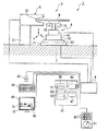
図1に示すように、外観検査装置1は、不図示のフレームなどに固定されたベース部2を有し、ベース部2上に検査部3が搭載されている。検査部3は、検査対象であるウェハWが載置されるウェハ保持部4と、ウェハ保持部4に近接して配置され、ウェハWの周縁部の画像を取得する周縁撮像部5と有する。ウェハ保持部4と周縁撮像部5は、装置制御部6で制御されている。なお、周縁撮像部5に加えてウェハWの全面を観察可能な顕微鏡などの表面検査部を設けても良い。
As shown in FIG. 1, the
ウェハ保持部4は、ベース部2に固定され、図1にXで示す水平方向に移動可能なXステージ11を有し、Xステージ11上にはX軸に直交する水平方向であるY軸に移動可能なYステージ12が搭載されている。さらに、Yステージ12上には、XY方向に直交する高さ方向でZ方向に移動可能なZステージ13が搭載されている。これによって、ウェハ保持部4は、周縁撮像部5に対してウェハWを相対的に3次元に移動させることができる。さらに、Zステージ13には、回転部14が設けられている。回転部14は、Z軸回りに回転可能な回転軸15を有する。各ステージ11〜13及び回転軸15の駆動は、サーボモータや、ボールネジ、減速機構を用いて行われる。駆動源は、ステッピングモータや、リニアモータを使用できる。回転軸15の上端には、吸着ステージ16が設けられている。吸着ステージ16の上面には、ウェハWを真空吸着によって保持する不図示の吸着部が設けられている。
The
周縁撮像部5は、ベース部2に固定されたアーム部21で支えられている。周縁撮像部5は、側面視でウェハWの周縁部を受け入れ可能な凹部22を有する略C字形状を有し、ウェハWの周縁部を撮像可能なカメラが配設されている。図2に3眼式の周縁撮像部の一例を示す。カメラは、ウェハWの周縁部の上面を撮像可能な第一のカメラ25と、ウェハWの周縁部の側面を撮像可能な第二のカメラ26と、ウェハWの周縁部の下面を撮像可能な第三のカメラ27とを有する。各カメラ25〜27は、CCD(Charge Coupled Device)などの撮像素子28と、フォーカス機能付きズームレンズ29とを有し、光軸上にハーフミラー30を設置することで、照明装置31を用いた同軸照明が可能に構成されている。なお、カメラの数は、1つ又は5つなど、任意に変更できる。カメラを1つだけ使用するときは、カメラを移動自在に支持することで撮像位置を変更可能にするか、カメラを固定して可動式のミラーで撮像位置を変更可能にする。照明装置31は、同軸照明に限定されずに、カメラ25〜27から離れた位置に1つ又は複数設けても良い。照明装置31は、周縁部が明視野で観察できるようにすることが好ましい。
The
図1に示す装置制御部6は、ウェハ保持部4の各ステージ11〜13及び回転部14の駆動制御や、吸着用の真空引きの制御と、周縁撮像部5の各カメラ25〜27のズーム調整、フォーカス調整、照明装置31の調光と、各カメラ25〜27の画像信号の受け取りを行う。例えば、モータのドライバ回路や、真空引き用のバルブの開閉を制御するドライバ回路などから構成されている。さらに、装置制御部6は、コンピュータ41にも接続されている。
The
コンピュータ41は、マウス42やキーボード43などの入力装置と、各種の設定や、周縁部の画像を表示するモニタ44とが接続された汎用のコンピュータである。マウス42、キーボード43、モニタ44は、検査者が操作できるインターフェイスである。コンピュータ41は、装置制御部6やマウス42、キーボード43、モニタ44が接続されるI/O(Input/Output)装置45と、制御部46と、レシピなどのデータを記憶する記憶装置47とを有する。制御部46は、CPU(中央演算装置)などから構成され、レシピに従って検査を実施する検査制御部51と、割り込み処理を行わせる割り込み処理部52と、レシピの登録をするレシピ登録部53とに機能分割することができる。なお、コンピュータ41は、外観検査装置1に搭載されても良いし、装置とは別に設けられても良い。コンピュータ41と装置制御部6で一つの制御装置を形成しても良い。
The
ここで、図3にモニタ44の画面表示の一例を示す。この画面は検査条件の設定に用いられる検査条件設定部となる。検査条件設定部として提供される機能選択画面70は、モニタ44の画面の下側に配置され、画面上からカメラ25〜27のズームを調整する「ZOOM」のスクロールバー71と、カメラ25〜27のフォーカスを調整する「FOCUS」のスクロールバー72と、調光に用いる「LIGHT」のスクロールバー73と、ウェハWの回転速度を調整する「SPEED」のスクロールバー74とが配列表示されている。各スクロールバー71〜74は、横方向に細長なスクロールボックス75を有し、スクロールボックス75中には現在のスクロール位置を示すスクロールサム76が設けられており、スクロールボックス75の両端には、スクロールアロー77が1つずつ設けられている。スクロールアロー77は、マウス42のポインタ78でクリック可能である。スクロールサム76は、マウス42でドラッグして移動させることができる。また、キーボード43の矢印キーで移動させることも可能である。
さらに、各スクロールバー71〜74の隣りには、現在のスクロール位置に対応する設定値の表示欄71A〜74Aが検査条件の項目ごとに設けられている。例えば、「ZOOM」のスクロールバー71に関連付けて表示されている設定値「×5.00」は、ズーム倍率として5倍が選択されていることを示す。この数値の表示欄71A〜74Aをマウス42でクリックしてアクティブにした状態で、数値をキーボード43から入力すると、その検査条件を設定することもできる。この場合には、入力された数値に合わせて、スクロールサム76が移動する。
Here, an example of the screen display of the
Further, adjacent to each of the
なお、図示していないが、検査条件設定部として提供される機能選択画面には、この他にもウェハWの位置を設定するために、XYZ方向のそれぞれについて条件を入力可能なスクロールバーや、ウェハWの周方向の位置を設定するスクロールバーを設けることができる。これらのスクロールバーは、機能選択画面70上に設けられても良いし、機能選択画面70と切り替えて表示可能な他の機能選択画面に配設しても良い。
Although not shown in the drawings, the function selection screen provided as the inspection condition setting unit also has a scroll bar for inputting conditions for each of the XYZ directions in order to set the position of the wafer W, A scroll bar for setting the circumferential position of the wafer W can be provided. These scroll bars may be provided on the
次に、この実施の形態の作用について説明する。
ロボットなどで搬送されてきたウェハWは、不図示のアライメント装置でアライメントされ、吸着ステージ16の回転中心にウェハWの中心を合わせて載置される。装置制御部6によって吸着部がウェハWの裏面の中心付近を真空吸着する。
ウェハ保持部4の位置決めして載置されたウェハWには、予め登録されているレシピに従って周縁部の検査が行われる。コンピュータ41は、検査者によって選択されたレシピを記憶装置47から読み込んで、検査制御部51に実行させる。レシピは、所定の位置の周縁部の画像を確実に取得できるように、カメラ25〜27のズーム、フォーカス、照明、ウェハWの回転速度などの各種条件を定めたものであり、これに従って装置制御部6が指令信号をXステージ11などに出力する。レシピを設定するときには、図3に示すスクロールバー71〜74を使用することができる。コンピュータ41は、例えば、検査位置ごとにスクロールバー71〜74の変化を順番に記録して1枚のウェハWを検査するためのレシピを作成し、レシピ登録部53が記憶装置47に登録する。
Next, the operation of this embodiment will be described.
The wafer W transferred by a robot or the like is aligned by an alignment apparatus (not shown), and is placed with the center of the wafer W aligned with the rotation center of the
The wafer W that has been positioned and placed by the
レシピに従って検査を行うときは、マウス42などを操作して所望のレシピを読み出して実行させる。ウェハWが所定速度で回転し、カメラ25〜27が周縁部の画像を取得し、モニタ44に表示させる。周縁部の画像は、モニタ44の略中央に表示されるようにウェハ保持部4のXYZが調整されているので、検査者は、モニタ44を目視で確認して傷などの欠陥の有無を検査する。検査は、周方向に所定の距離をおいて複数箇所行うが、周方向に連続して行っても良い。また、基準画面を予め入力して観察中の画面との差分を取り、その値が予め設定した閾値を越えたら欠陥とみなすなど、画像処理によって欠陥を自動的に抽出するようにしても良い。
予定されていた検査位置について、欠陥の有無を検査できた場合には、ウェハWの回転を停止させ、吸着を解除してからロボットでウェハWを搬出する。
When inspecting according to a recipe, a desired recipe is read and executed by operating the
If the presence or absence of a defect can be inspected at the scheduled inspection position, the rotation of the wafer W is stopped, the suction is released, and the wafer W is then unloaded by the robot.
これに対して、ウェハWが反っていた場合には、カメラ25〜27の焦点からウェハWの周縁部が外れることがある。また、照明装置31の光量が適切でなくなって、十分な明るさが得られなかったり、明るすぎたりすることがある。これらの場合には、検査条件を変更しなければ、外観検査ができなくなる。
さらに、欠陥が判別可能に表示されているが、モニタ44の端に表示されて見難くかったり、検査者の体調等によっては回転速度が速すぎると感じたりすることがある。検査者が異なる場合には、その習熟度によっては回転速度の調整が必要なこともある。このような場合は、検査が不能ではないが、検査条件を変更することが好ましい。
これらの場合、検査者は、割り込みボタンを押して、検査中に検査条件を変化する。なお、割り込みボタンは、コンピュータ41がモニタ44にマウス42等で操作可能なボタンをGUI(Graphical User Interface)として提供しても良いし、不図示の操作パネル上にハードウェア的に設けられても良い。図3の下方にGUIとしてモニタ44上に設けられる割り込みボタンと、割り込み処理を解除するボタンの例を示す。モニタ44の略全面に検査中の周縁部の画像81が表示され、その下方に割り込みボタン82と、割り込み解除ボタン83とが並んで配置されている。
On the other hand, when the wafer W is warped, the peripheral edge of the wafer W may deviate from the focal points of the
Further, although the defect is displayed so as to be discriminable, it may be difficult to see because it is displayed at the end of the
In these cases, the inspector presses the interrupt button to change the inspection conditions during the inspection. The interrupt button may be provided as a GUI (Graphical User Interface) that can be operated by the
図4に割り込み操作時のフローチャートを示す。ステップS101で予め登録してあるレシピを実行する。検査が終了する前に(ステップS102でNo)、検査者が割り込みボタン82を押したら(ステップS103でYes)、割り込み処理部52がモニタ44が周縁部の画像81から、検査条件設定部、つまり機能選択画面70で設定変更が可能になるので、マウス42等でスクロールバー71〜73を操作して検査条件を変更する(ステップS104)。例えば、ウェハWの変形などによってフォーカスがあっていない場合には、「FOCUS」のスクロールバー72を操作して、フォーカスを変化させる。また、ウェハWの位置が周縁撮像部5に対してずれていた場合には、画像81の端に周縁部が表示されるので、これを画像81の中央に移動させるときは、XYZの座標をそれぞれ設定可能な不図示のスクロールバーを表示させて、ウェハ保持部4のXYZを調整する。いずれの検査条件でも、予め設定可能な範囲が定められており、設定可能な範囲内で検査条件を変更できる。設定可能な範囲外の検査条件を選択しようとした場合には、インターロックがかかり、そのような入力は無効になる。
FIG. 4 shows a flowchart at the time of interrupt operation. In step S101, a recipe registered in advance is executed. If the inspector presses the interrupt button 82 (No in step S103) before the inspection is completed (No in step S102), the interrupt processing
そして、検査条件を変更しつつ観察を継続する(ステップS105)。周縁部にカメラ25〜27のフォーカスが合うので、モニタ44に表示された画像を目視で確認してウェハWの周縁部の欠陥の有無を調べる。さらに、必要に応じて不図示の保存ボタンを押すことにより画像を保存する(ステップS106)。この画像は、例えば、欠陥の状態をデータとして保有しておく必要がある場合や、その画像を使ってプロセス改良などを行う場合に保存される。そして、例えば、プロセスを中止せざるを得ない傷等が発見された場合には、不図示の終了ボタンを押すことにより、この段階で検査を終了する(ステップS107でYes)。
And observation is continued, changing inspection conditions (Step S105). Since the
欠陥が発見されなかった場合や、欠陥があってもプロセスを続行できる場合には(ステップS107でNo)、ステップS108に進む。現在の機能選択画面70に表示されていない検査条件を追加的に変更する必要がある場合には、不図示のページ変更ボタンを押すことにより(ステップS108でYes)、ステップS104に戻る。例えば、撮像角度をさらに調整する必要がある場合や、他の照明装置を点灯させるなどのような他の検査条件を変更する必要がある場合などがあげられる。
これに対して、これ以上の検査条件の変更が不要である場合は(ステップS108でNo)、割り込み処理部52が割り込み解除ボタン83が押されたか判定する(ステップS109)。割り込み解除ボタン83が押されたときは、割り込み処理部52が割り込み処理を解除させ(ステップS110)、検査条件をレシピ設定値に戻し、ステップS101に進み、検査制御部51が通常のレシピに従って検査を続行する。このとき、割り込み処理を開始したときの検査位置や検査条件から検査が再開される。
If no defect is found or if the process can be continued even if there is a defect (No in step S107), the process proceeds to step S108. If it is necessary to additionally change inspection conditions that are not displayed on the current
On the other hand, if it is not necessary to change the inspection condition any more (No in step S108), the interrupt processing
ステップS109で割り込み解除ボタン83が押されていない場合は、変更された検査条件のままでステップS101に戻って継続して検査を行う。
なお、検査条件変更後、図1のモニタ44に表示されているレシピ登録ボタン93を押すと、レシピ登録部53がレシピを登録し、ステップS104で変更した条件で既存のレシピが上書き登録される。なお、既存のレシピとは別に新しいレシピとして登録するようにしても良い。また、レシピ登録ボタン93は、ハードウェア上に設けられても良い。
If the interrupt
If the
この実施の形態では、予め作成しておいたレシピに従って周縁部の検査を行っているときに、基本的なレシピ動作を変更することなく、観察に関する検査条件を変更する割り込み処理を行えるようにしたので、ウェハWの固体差があって正確な検査が困難な場合でも、調整しながら検査を行うことができる。外観検査装置1を完全に停止させなくても検査を行うことができる。レシピをその都度作り直す必要がなくなり、処理が容易になる。検査条件を変えたい場所で割り込み処理を行うことができるので、条件変更後に継続して所望する位置の検査が行える。従来の構成では、レシピを変更した場合には、最初から検査をやり直さなければならないが、この実施の形態では必要なところのみで検査条件を変更することができる。このような効果は、検査者が異なる場合や、検査者の疲労度に合わせて検査条件を変更した場合についても同様である。
検査条件を変更する場合には、検査条件設定部として画面表示されるスクロールバー71〜74を操作すれば良いので、操作が容易である。スクロールサム76の位置で調整可能な範囲内のどの辺りの条件を使用しているかを目視で認識でき、イメージとして捉え易い。具体的な設定値が表示欄71A〜74Aに設定項目と関連付けて表示されるから、検査条件の変更を確認し易い。さらに、条件変更によって新たにレシピが登録されるので、このレシピを使って以降の検査を行うことができる。
In this embodiment, when a peripheral portion is inspected according to a recipe prepared in advance, an interrupt process for changing inspection conditions related to observation can be performed without changing the basic recipe operation. Therefore, even when there is a difference between individual wafers W and accurate inspection is difficult, the inspection can be performed while adjusting. The inspection can be performed without completely stopping the
When changing the inspection condition, it is only necessary to operate the
なお、一般にカメラの倍率が上がったときは、ウェハの回転速度を落とした方が観察し易いので、予めコンピュータ41にカメラ25〜27の倍率と、その倍率において観察し易い回転速度との関係を予め記憶させておき、ズームで画像を拡大させたときはウェハWの回転速度が自動的に変化するように構成しても良い。このように、複数の検査条件を関連付けて調整する場合に、対象となる設定項目は、倍率と回転速度に限定されない。
In general, when the magnification of the camera is increased, it is easier to observe if the rotation speed of the wafer is decreased. Therefore, the
(第2の実施の形態)
この実施の形態は、割り込み時の処理が異なることを主な特徴とする。なお、図5に示す外観検査装置1は、入力装置としてジョグダイヤル91が追加されている以外は第一の実施の構成と同じ装置構成である。
ジョグダイヤル91は、データ入力用のインターフェイスであり、指で回転させて使用する。ジョグダイヤル91の回転方向、回転速度によって各設定項目の調整が行える。例えば、ズーム機能であれば、ジョグダイヤル91をゆっくり回転させると倍率の変動が小さく、回転速度を速めると倍率の変動が大きくなる。例えば、低倍ではゆっくり回して倍率を徐々に変動させ、高倍率になる従って速く回転させ、素早く変動させることが可能になる。倍率を下げるときには高倍率から低倍率に素早く倍率を下げることができる。また、ジョグダイヤル91を速く回転させて、粗く倍率を合わせ、その後、ジョグダイヤル91をゆっくり回転させて適切な倍率に合わせることもできる。レシピを登録する場合、コンピュータ41は、検査者がジョグダイヤル91を操作した通りに、レシピを記憶させることもできる。
(Second Embodiment)
This embodiment is mainly characterized in that processing at the time of interruption is different. The
The
ジョグダイヤル91には、機能切り替えスイッチ92が複数設けられている。機能切り替えスイッチ92を選択することで、検査条件の項目を切り替えることができる。例えば、ズーム機能に割り当てられた機能切り替えスイッチ92を押してからジョグダイヤル91を回転させると、ズームの検査条件を調整できる。回転速度に割り当てられた機能切り替えスイッチ92を押してからジョグダイヤル91を回転させると、回転速度の検査条件を調整できる。機能切り替えスイッチ92は、検査条件の項目の数と同じ数だけ配設することが好ましいが、1つの機能切り替えスイッチ92を押すごとに、設定される検査条件の項目が1つずつ順番に切り替えられるようにしても良い。省スペース化が図れる。また、項目の数だけジョグダイヤル91を備える場合には、機能切り替えスイッチ92は不要になる。
The
割り込み処理は、図6のフローチャートに示すように、ステップS101からステップS108までは第1の実施の形態と略同じである。すなわち、レシピ実行中にステップS103で割り込みボタン82が押された時点で、レシピを中断し、レシピ中断時の情報を記憶しておく。そして、検査条件を変更したら(ステップS104)、変更した検査条件でマニュアル操作による観察を実施する(ステップS105A)。マニュアル操作には、ジョグダイヤル91を使用するが、モニタ44に表示されるスクロールバー71〜74を使用しても良い。回転スピードをジョグダイヤル91に割り当てたとき、ジョグシャトル91を逆回転させると吸着ステージ16も逆転する。
As shown in the flowchart of FIG. 6, the interrupt processing is substantially the same as that of the first embodiment from step S101 to step S108. That is, when the interrupt
マニュアル操作による検査が不要になったら割り込み解除ボタン83を押す(ステップS201)。割り込み解除ボタン83を押すことにより、割り込みボタン82が押された時点の状態に戻って復帰する(ステップS202)。
When inspection by manual operation is no longer necessary, the interrupt
この実施の形態では、割り込み処理を可能にすることで第1の実施の形態と同様の効果が得られる。さらに、条件変更によって新たにレシピが登録されるので、このレシピを使って以降の検査を行うことができる。 In this embodiment, the same effect as that of the first embodiment can be obtained by enabling interrupt processing. Furthermore, since a recipe is newly registered by changing the conditions, the subsequent inspection can be performed using this recipe.
なお、本発明は、前記の実施の形態に限定されずに広く応用することができる。
例えば、ジョグダイヤル91は、図1に示す外観検査装置に設けても良い。また、図6に示す外観検査装置はジョグダイヤル91を有しなくても良い。また、ジョグダイヤル91の代わりにジョイスティック等を使用しても良い。
ウェハ保持部4は、ウェハWをXYZの3方向に移動可能で、かつウェハWを回転させることができるものであれば良く、実施の形態の構成に限定されない。また、ウェハWをXYZに移動させる代わりに、周縁撮像部5をXステージ、Yステージ、Zステージに搭載させて、XYZの3方向に移動可能にしても良い。さらに、XYZの少なくとも1方向に移動可能な機構をウェハ保持部4側に設け、残りの2方向に移動可能な機構を周縁撮像部5側に設けても良い。
Note that the present invention can be widely applied without being limited to the above-described embodiment.
For example, the
The
1 外観検査装置
4 ウェハ保持部
5 周縁撮像部
42 マウス(入力装置)
43 キーボード(入力装置)
52 割り込み処理部(検査条件設定部)
53 レシピ登録部
70 機能選択画面
71,72,73,74 スクロールバー
71A,72A,73A,74A 表示欄
W ウェハ
DESCRIPTION OF
43 Keyboard (input device)
52 Interrupt processing section (inspection condition setting section)
53
Claims (5)
レシピに従ってウェハの周縁部の外観検査を行っている途中に、レシピに従った検査を中断させ、割り込み処理を実行する割り込み処理部と、
割り込み処理として、レシピと異なる検査条件で検査を行えるように、検査条件の項目ごとに検査条件の変更を入力可能な検査条件設定部と、
検査者が前記検査条件設定部に検査条件を入力するために用いられる入力装置と、
を備えることを特徴とする外観検査装置。 In an appearance inspection apparatus that has a wafer holding unit that rotatably holds a wafer and a peripheral imaging unit that acquires an enlarged image of the peripheral part of the wafer, and inspects the peripheral part of the wafer according to a preset recipe,
An interrupt processing unit that interrupts the inspection according to the recipe and performs the interrupt processing while performing the appearance inspection of the peripheral portion of the wafer according to the recipe;
As an interrupt process, an inspection condition setting unit that can input inspection condition changes for each inspection condition item so that inspection can be performed under different inspection conditions from the recipe,
An input device used by an inspector to input inspection conditions to the inspection condition setting unit;
An appearance inspection apparatus comprising:
レシピに従ってウェハの周縁部の外観検査を行っている途中に、検査者からの指令を受けて、レシピに従った検査を中断させ、検査者が変更した検査条件で検査を実施し、異なる検査条件での検査が終了した後に、レシピによる検査を再開させることを特徴とする外観検査方法。 In the appearance inspection method for observing an enlarged image of the peripheral portion while rotating the wafer according to a preset recipe, and performing an appearance inspection of the peripheral portion of the wafer,
During the appearance inspection of the peripheral edge of the wafer according to the recipe, in response to an instruction from the inspector, the inspection according to the recipe is interrupted, and the inspection is performed under the inspection conditions changed by the inspector. An appearance inspection method, wherein inspection by a recipe is resumed after inspection at the end.
Priority Applications (4)
| Application Number | Priority Date | Filing Date | Title |
|---|---|---|---|
| JP2006268478A JP2008089351A (en) | 2006-09-29 | 2006-09-29 | Visual inspection device and its method |
| CNA2007101616576A CN101158649A (en) | 2006-09-29 | 2007-09-27 | Visual inspection apparatus and visual inspection method |
| US11/906,072 US20080079932A1 (en) | 2006-09-29 | 2007-09-28 | Visual inspection apparatus and visual inspection method |
| TW096136196A TW200822260A (en) | 2006-09-29 | 2007-09-28 | Visual inspection apparatus and visual inspection method |
Applications Claiming Priority (1)
| Application Number | Priority Date | Filing Date | Title |
|---|---|---|---|
| JP2006268478A JP2008089351A (en) | 2006-09-29 | 2006-09-29 | Visual inspection device and its method |
Publications (2)
| Publication Number | Publication Date |
|---|---|
| JP2008089351A true JP2008089351A (en) | 2008-04-17 |
| JP2008089351A5 JP2008089351A5 (en) | 2009-01-15 |
Family
ID=39260790
Family Applications (1)
| Application Number | Title | Priority Date | Filing Date |
|---|---|---|---|
| JP2006268478A Withdrawn JP2008089351A (en) | 2006-09-29 | 2006-09-29 | Visual inspection device and its method |
Country Status (4)
| Country | Link |
|---|---|
| US (1) | US20080079932A1 (en) |
| JP (1) | JP2008089351A (en) |
| CN (1) | CN101158649A (en) |
| TW (1) | TW200822260A (en) |
Cited By (1)
| Publication number | Priority date | Publication date | Assignee | Title |
|---|---|---|---|---|
| WO2009154182A1 (en) * | 2008-06-18 | 2009-12-23 | 株式会社コベルコ科研 | Edge surface observation apparatus |
Families Citing this family (9)
| Publication number | Priority date | Publication date | Assignee | Title |
|---|---|---|---|---|
| DE102007024525B4 (en) * | 2007-03-19 | 2009-05-28 | Vistec Semiconductor Systems Gmbh | Apparatus and method for evaluating defects at the edge area of a wafer |
| US20110199480A1 (en) * | 2009-07-09 | 2011-08-18 | Camtek Ltd. | Optical inspection system using multi-facet imaging |
| US8786850B2 (en) * | 2012-10-29 | 2014-07-22 | Kla-Tencor Corporation | Illumination energy management in surface inspection |
| US10127523B2 (en) | 2013-03-20 | 2018-11-13 | Lifetime Brands, Inc. | Method and apparatus for mobile quality management inspections |
| CN105472252B (en) * | 2015-12-31 | 2018-12-21 | 天津远度科技有限公司 | A kind of unmanned plane obtains the system and method for image |
| TWI628428B (en) * | 2016-12-16 | 2018-07-01 | 由田新技股份有限公司 | A multi-angled defect capturing device and a multi-angled defect inspecting apparatus having the same |
| CN108508031A (en) * | 2017-02-28 | 2018-09-07 | 上海微电子装备(集团)股份有限公司 | A kind of double-side detecting device and detection method |
| CN114088724B (en) * | 2021-11-20 | 2023-08-18 | 深圳市北科检测科技有限公司 | Display screen edge defect detection device |
| CN114113140B (en) * | 2021-11-26 | 2023-07-07 | 深圳市北科检测科技有限公司 | Multi-station LED lamp panel detection device |
Family Cites Families (3)
| Publication number | Priority date | Publication date | Assignee | Title |
|---|---|---|---|---|
| KR100416791B1 (en) * | 2001-03-19 | 2004-01-31 | 삼성전자주식회사 | Microscope Apparatus and Inspection Method for Semiconductor Wafer Inspection |
| JP3629244B2 (en) * | 2002-02-19 | 2005-03-16 | 本多エレクトロン株式会社 | Wafer inspection equipment |
| JP2004227671A (en) * | 2003-01-23 | 2004-08-12 | Tdk Corp | Apparatus for manufacturing optical recording medium |
-
2006
- 2006-09-29 JP JP2006268478A patent/JP2008089351A/en not_active Withdrawn
-
2007
- 2007-09-27 CN CNA2007101616576A patent/CN101158649A/en active Pending
- 2007-09-28 TW TW096136196A patent/TW200822260A/en unknown
- 2007-09-28 US US11/906,072 patent/US20080079932A1/en not_active Abandoned
Cited By (2)
| Publication number | Priority date | Publication date | Assignee | Title |
|---|---|---|---|---|
| WO2009154182A1 (en) * | 2008-06-18 | 2009-12-23 | 株式会社コベルコ科研 | Edge surface observation apparatus |
| JP2010002216A (en) * | 2008-06-18 | 2010-01-07 | Kobelco Kaken:Kk | Observation device of edge surface |
Also Published As
| Publication number | Publication date |
|---|---|
| TW200822260A (en) | 2008-05-16 |
| CN101158649A (en) | 2008-04-09 |
| US20080079932A1 (en) | 2008-04-03 |
Similar Documents
| Publication | Publication Date | Title |
|---|---|---|
| JP2008089351A (en) | Visual inspection device and its method | |
| US7456947B2 (en) | Inspecting apparatus and inspecting method | |
| JP2008091476A (en) | Device for inspecting appearance | |
| KR100416791B1 (en) | Microscope Apparatus and Inspection Method for Semiconductor Wafer Inspection | |
| JP5060808B2 (en) | Appearance inspection device | |
| JPH03296011A (en) | Magnification varying device for microscope | |
| JP2013083743A (en) | Magnifying observation device | |
| JP2007234932A (en) | Device for checking external appearance | |
| JP5893314B2 (en) | Display device and microscope system | |
| JP2003015056A (en) | Method and device for picking up image | |
| JP5091460B2 (en) | Inspection and measurement equipment | |
| JP2004179581A (en) | Semiconductor wafer inspection device | |
| JP2003114201A (en) | Fluoroscopic radiographic apparatus | |
| JP2007327903A (en) | Visual inspection system | |
| JP2008091690A (en) | Appearance inspection equipment | |
| JP6150504B2 (en) | Imaging system | |
| JP2009186414A (en) | Inspection microscope, microscope observation method, and microscopic observation program | |
| TWI288449B (en) | Semiconductor wafer inspection apparatus | |
| JP2601727B2 (en) | Liquid crystal display panel inspection equipment | |
| JP2009188226A (en) | Visual inspection equipment and visual inspection method | |
| JP2010256724A (en) | Observation device | |
| JP2002090633A (en) | Microscope | |
| JP2007292683A (en) | Sample measuring apparatus and sample stage adjusting method of sample measuring apparatus | |
| JP2007248714A (en) | Multiple-head microscope system | |
| JPH0461356A (en) | Control circuit for x-y stage |
Legal Events
| Date | Code | Title | Description |
|---|---|---|---|
| A521 | Written amendment |
Free format text: JAPANESE INTERMEDIATE CODE: A523 Effective date: 20081125 |
|
| A621 | Written request for application examination |
Free format text: JAPANESE INTERMEDIATE CODE: A621 Effective date: 20081125 |
|
| A761 | Written withdrawal of application |
Free format text: JAPANESE INTERMEDIATE CODE: A761 Effective date: 20100304 |