JP2008072696A - Focusing information visualization device, and corresponding method, program and recording medium - Google Patents
Focusing information visualization device, and corresponding method, program and recording medium Download PDFInfo
- Publication number
- JP2008072696A JP2008072696A JP2007178811A JP2007178811A JP2008072696A JP 2008072696 A JP2008072696 A JP 2008072696A JP 2007178811 A JP2007178811 A JP 2007178811A JP 2007178811 A JP2007178811 A JP 2007178811A JP 2008072696 A JP2008072696 A JP 2008072696A
- Authority
- JP
- Japan
- Prior art keywords
- edge
- focus
- focusing
- image
- information
- Prior art date
- Legal status (The legal status is an assumption and is not a legal conclusion. Google has not performed a legal analysis and makes no representation as to the accuracy of the status listed.)
- Withdrawn
Links
Images


Classifications
-
- G—PHYSICS
- G03—PHOTOGRAPHY; CINEMATOGRAPHY; ANALOGOUS TECHNIQUES USING WAVES OTHER THAN OPTICAL WAVES; ELECTROGRAPHY; HOLOGRAPHY
- G03B—APPARATUS OR ARRANGEMENTS FOR TAKING PHOTOGRAPHS OR FOR PROJECTING OR VIEWING THEM; APPARATUS OR ARRANGEMENTS EMPLOYING ANALOGOUS TECHNIQUES USING WAVES OTHER THAN OPTICAL WAVES; ACCESSORIES THEREFOR
- G03B13/00—Viewfinders; Focusing aids for cameras; Means for focusing for cameras; Autofocus systems for cameras
-
- G—PHYSICS
- G03—PHOTOGRAPHY; CINEMATOGRAPHY; ANALOGOUS TECHNIQUES USING WAVES OTHER THAN OPTICAL WAVES; ELECTROGRAPHY; HOLOGRAPHY
- G03B—APPARATUS OR ARRANGEMENTS FOR TAKING PHOTOGRAPHS OR FOR PROJECTING OR VIEWING THEM; APPARATUS OR ARRANGEMENTS EMPLOYING ANALOGOUS TECHNIQUES USING WAVES OTHER THAN OPTICAL WAVES; ACCESSORIES THEREFOR
- G03B17/00—Details of cameras or camera bodies; Accessories therefor
- G03B17/18—Signals indicating condition of a camera member or suitability of light
-
- H—ELECTRICITY
- H04—ELECTRIC COMMUNICATION TECHNIQUE
- H04N—PICTORIAL COMMUNICATION, e.g. TELEVISION
- H04N23/00—Cameras or camera modules comprising electronic image sensors; Control thereof
- H04N23/60—Control of cameras or camera modules
- H04N23/63—Control of cameras or camera modules by using electronic viewfinders
- H04N23/633—Control of cameras or camera modules by using electronic viewfinders for displaying additional information relating to control or operation of the camera
- H04N23/635—Region indicators; Field of view indicators
Landscapes
- Physics & Mathematics (AREA)
- General Physics & Mathematics (AREA)
- Engineering & Computer Science (AREA)
- Multimedia (AREA)
- Signal Processing (AREA)
- Studio Devices (AREA)
- Facsimile Image Signal Circuits (AREA)
- Color Image Communication Systems (AREA)
- Focusing (AREA)
- Automatic Focus Adjustment (AREA)
Abstract
Description
本発明は、写真画像の合焦情報を画面上に表示して視覚化する技術に関する。 The present invention relates to a technique for displaying and visualizing focusing information of a photographic image on a screen.
近年、液晶ディスプレイを搭載したデジタルスチルカメラやカメラ付き携帯電話が普及している。こうした撮像装置では、通常、撮像した画像のブレ・ボケの状況を液晶ディスプレイで確認することができる。こうした確認作業を確実に行うために、例えば、下記の特許文献に記載の装置が知られている。 In recent years, digital still cameras and camera-equipped mobile phones equipped with a liquid crystal display have become widespread. In such an imaging apparatus, it is usually possible to confirm the blurring / blurring situation of a captured image on a liquid crystal display. In order to perform such confirmation work reliably, for example, an apparatus described in the following patent document is known.
特許文献1は、画像の所定の領域のエッジの数を集計し、最もエッジの多い領域の画像を確認用画像として抽出・表示する画像処理装置を開示している。また、特許文献2は、画像データをフーリエ変換して、高周波成分が所定の割合よりも少ない画像であれば、劣化強調処理を施して表示する画像処理装置を開示している。
しかしながら、こうした画像処理装置は、合焦判定の一助とはなり得るものの、合焦の位置を正確に判定しているとは言えない。そこで、合焦の位置まで含めて、より確実に合焦の状況を確認できる装置が求められていた。 However, although such an image processing apparatus can assist in focus determination, it cannot be said that the position of focus is accurately determined. Therefore, there has been a demand for a device that can confirm the in-focus state more reliably including the in-focus position.
上記課題を解決する本発明は、合焦情報視覚化装置、合焦情報視覚化方法および合焦情報視覚化プログラムとして、以下に適用例として示した構成により実現される。 The present invention that solves the above-described problems is realized by the configuration described below as an application example as a focusing information visualization device, a focusing information visualization method, and a focusing information visualization program.
[適用例1]
写真画像の合焦情報を画面上に視覚化する合焦情報視覚化装置であって、
前記写真画像の各画素の輝度情報に基づいて、該画像に存在するエッジのうち、合焦の条件に合致するエッジを抽出するエッジ抽出手段と、
該抽出されたエッジを用いて、合焦の情報を、前記画面上に視認可能に出力する合焦情報出力手段と
を備えた合焦情報視覚化装置。
[Application Example 1]
A focusing information visualization device that visualizes focusing information of a photographic image on a screen,
Based on the luminance information of each pixel of the photographic image, an edge extracting means for extracting an edge that matches the focusing condition among edges existing in the image;
A focus information visualization device comprising: focus information output means for outputting focus information so as to be visible on the screen using the extracted edge.
かかる合焦情報視覚化装置は、所定の合焦の条件を用いて、合焦していると判断できるエッジを抽出し、その結果に基づき、合焦の情報を画面上に視認可能に出力することができる。したがって、ユーザは、画面上で写真画像の合焦の状況を容易に確認することができ、写真画像の合焦判定を行う場合の有用な情報として利用できる。 Such a focus information visualization apparatus extracts an edge that can be determined to be in focus by using a predetermined focus condition, and outputs focus information on the screen so as to be visible based on the result. be able to. Accordingly, the user can easily check the focus state of the photographic image on the screen, and can be used as useful information when performing the focus determination of the photographic image.
[適用例2]
係る合焦情報視覚化装置において、
前記エッジ抽出手段は、
前記写真画像の各画素の輝度情報に基づいて該写真画像の各位置におけるエッジを検出するエッジ検出手段と、
前記検出されたエッジから第1の閾値以上の強さを有するエッジを抽出する第1のエッジ抽出手段と、
前記抽出されたエッジのエッジ幅を演算するエッジ幅演算手段と、
前記演算されたエッジ幅が第2の閾値以下であるエッジを抽出する第2のエッジ抽出手段と
を備えた合焦情報視覚化装置。
[Application Example 2]
In the focusing information visualization apparatus,
The edge extraction means includes
Edge detecting means for detecting an edge at each position of the photographic image based on luminance information of each pixel of the photographic image;
First edge extraction means for extracting an edge having a strength equal to or greater than a first threshold from the detected edge;
Edge width calculating means for calculating the edge width of the extracted edge;
A focus information visualization device comprising: second edge extraction means for extracting an edge whose calculated edge width is equal to or smaller than a second threshold value.
かかるエッジ抽出手段を有する合焦情報視覚化装置は、所定のエッジ強さ及びエッジ幅を有するエッジを抽出でき、合焦状況の判定を正確に行うことができる。 The focus information visualization apparatus having such an edge extraction means can extract an edge having a predetermined edge strength and edge width, and can accurately determine the focus state.
また、こうした合焦情報視覚化装置において、エッジの幅の抽出を次のように行なっても良い。つまり、エッジ検出手段により、写真画像を構成する各画素について、所定方向に並んだ画素間の輝度の差分の累積値が漸増または漸減している範囲をエッジとして検出し、第1のエッジ抽出手段により、この累積値が漸増または漸減した結果、累積値の絶対値が所定の閾値を超えたとき、エッジの抽出を行なう。その上で、エッジ幅演算手段により、抽出されたエッジの幅を、前記漸増または漸減の全期間として演算するのである。こうすることにより、より正確にエッジの幅を検出することができる。 In such a focusing information visualization apparatus, the edge width may be extracted as follows. That is, the edge detecting unit detects, as an edge, a range in which the cumulative value of the luminance difference between pixels arranged in a predetermined direction is gradually increased or decreased for each pixel constituting the photographic image, and the first edge extracting unit As a result of gradually increasing or decreasing the accumulated value, when the absolute value of the accumulated value exceeds a predetermined threshold value, an edge is extracted. Then, the edge width calculation means calculates the extracted edge width as the entire period of the gradual increase or decrease. By doing so, the edge width can be detected more accurately.
もとより、エッジ検出手段が、写真画像を構成する各画素について、所定方向に並んだ画素間の輝度の差分に基づいて、写真画像の各位置におけるエッジを検出するものとしても良い。係る構成は、画素間の輝度の差分を見るので、処理を簡略化し、高速に全範囲のエッジの検出を行なうことができる。 Of course, the edge detecting means may detect the edge at each position of the photographic image based on the luminance difference between the pixels arranged in a predetermined direction for each pixel constituting the photographic image. In such a configuration, since the luminance difference between pixels is seen, the processing can be simplified and the edge of the entire range can be detected at high speed.
[適用例3]
上記合焦情報視覚化装置であって、
前記合焦情報出力手段は、前記合焦の情報を抽出した前記画面上の位置の元画像を処理することにより表示の態様を変更して、前記合焦の情報の出力を行なう
合焦情報視覚化装置。
[Application Example 3]
The in-focus information visualization apparatus,
The focus information output means changes the display mode by processing the original image at the position on the screen from which the focus information is extracted, and outputs the focus information. Device.
係る合焦情報視覚化装置では、元画像の表示の態様を変更して合焦の情報の出力を行なうから、使用者は表示している画像の状態を見ながら、かつ合焦の情報を視認することができる。 In such a focus information visualization apparatus, since the display mode of the original image is changed and the focus information is output, the user can visually check the focus information while viewing the state of the displayed image. can do.
合焦情報出力手段による元画像の表示の態様の変更は、元画像に画像処理を施すことにより実現することができる。これにより、写真画像のうち、合焦していると判定されたエッジを有する画素、または当該エッジを有しない画素、あるいはその両方に対して、所定の画像処理を施して画面表示できるので、ユーザは、どのような色彩の写真画像であっても分かりやすく合焦判定位置を確認することができる。なお、画像処理とは、ユーザが合焦判定位置を視覚的に確認しやすいように写真画像に施す処理であり、白黒表示、非表示、補色表示、明度変更表示、ネガポジ反転表示、点滅表示など種々の処理が可能である。 The change of the display mode of the original image by the focusing information output unit can be realized by performing image processing on the original image. As a result, a predetermined image processing can be performed on a pixel having an edge determined to be in focus, a pixel not having the edge, or both of the photographic image, so that the user can display the screen. In any color of the photographic image, it is possible to easily confirm the focus determination position. Image processing is processing that is performed on a photographic image so that the user can easily confirm the focus determination position, such as black and white display, non-display, complementary color display, brightness change display, negative / positive inversion display, and blinking display. Various processes are possible.
合焦情報視覚化装置での合焦情報出力手段による表示の態様の変更は、合焦の情報を抽出した位置の原画像を、次のいずれか一つの態様により表示することにより行なうことができる。すなわち、
明度が所定以上のグレー画像に変更すること、
該グレー画像と元画像とを交互に表示する態様に変更すること、
元画像をネガポジ反転した画像に変更すること、
前記エッジが前記合焦の条件に合致する度合いに応じて異なる2以上の表示の態様に変更すること
のうちのいずれか一つの態様である。
The change of the display mode by the focus information output unit in the focus information visualization device can be performed by displaying the original image at the position where the focus information is extracted in any one of the following modes. . That is,
Changing to a gray image with a lightness above a certain level,
Changing to a mode of alternately displaying the gray image and the original image;
Changing the original image to a negative-positive inverted image,
It is any one aspect in which it changes into two or more different display modes according to the degree to which the edge meets the condition for focusing.
こうした合焦の情報は、合焦の条件に合致するエッジの位置に所定の表示を行うことで視認可能に表示されしてもよい。例えば、エッジの位置に予め設定した符号などを表示するといったことを考えることができる。当該エッジの位置は、合焦していると装置に判定される被写体の輪郭を表すことが多く、ユーザは写真画像の合焦状況を判定する場合の有用な情報としてこれを利用することができる。 Such in-focus information may be displayed so as to be visible by performing a predetermined display at the edge position that matches the in-focus condition. For example, it can be considered to display a preset code or the like at the edge position. The edge position often represents the contour of the subject that is determined by the apparatus to be in focus, and the user can use this information as useful information when determining the in-focus state of a photographic image. .
更に、こうした合焦の情報は、合焦の条件に合致するエッジの位置に該エッジの幅に応じて異なる態様で表示することで、視認可能な出力とすることができる。これにより、ユーザは、装置の合焦判定位置だけでなく合焦の程度についても把握することができ、合焦状況を判定するより詳細な情報として利用できる。 Further, such in-focus information can be displayed as a visually recognizable output by displaying the information at different positions according to the width of the edge at the position of the edge that matches the in-focus condition. Accordingly, the user can grasp not only the focus determination position of the apparatus but also the degree of focus, and can be used as more detailed information for determining the focus state.
あるいは、こうした合焦情報視覚化装置において、合焦情報出力手段は、合焦の情報を写真画像と重ね合わせて出力する手段とすることができる。これにより、ユーザは、写真画像を照合しながら、分かりやすく合焦判定位置を確認することができる。 Alternatively, in such an in-focus information visualization apparatus, the in-focus information output unit can be a unit that outputs the in-focus information superimposed on the photographic image. Thereby, the user can confirm the focus determination position in an easy-to-understand manner while collating photographic images.
さらに、合焦情報出力手段は、合焦の条件に合致するエッジを含む少なくとも1の領域を、枠画像を用いて区分された区画として前記画面上に表示する手段と、この区画のうち1の区画がユーザ操作により指定された時、指定された区画に属する写真画像を所望の倍率に拡大して画面上に出力する手段とを備えたものとすることができる。これにより、ユーザは、写真画像の合焦の状況について、合焦情報視覚化装置の合焦判定結果を参考にしつつ、自らの視覚に基づいても効率的に確認することができる。 Further, the focus information output means displays at least one region including an edge that matches the focus condition on the screen as a section partitioned using a frame image, and one of the sections. When a section is designated by a user operation, a means for enlarging a photographic image belonging to the designated section to a desired magnification and outputting it on the screen can be provided. Accordingly, the user can efficiently check the in-focus state of the photographic image based on his / her own vision while referring to the in-focus determination result of the in-focus information visualization apparatus.
また、こうした合焦情報視覚化装置には、更に、写真画像を印刷する印刷媒体の大きさを指定する印刷媒体指定手段を備えるものとし、エッジ抽出手段では、指定された印刷媒体の大きさと、写真画像大きさとに基づいて、合焦の条件に合致するとして検出するエッジの条件を定め、この条件に基づいて、エッジの抽出を行なうものとしても良い。合焦しているかどうかは、結局印刷したときの見た目の問題であり、印刷される印刷媒体(多くは印刷用紙)の大きさによっては、同じ合焦の状況であっても、見た目の印象は相違する。したがって、印刷媒体の大きさと写真画像の大きさとに基づいて、エッジを検出する条件を変え、結果的に合焦の情報の視覚化の態様を変えることは有用である。 The focusing information visualization apparatus further includes a print medium designating unit that designates the size of the print medium on which the photographic image is printed. In the edge extraction unit, the size of the designated print medium, Based on the size of the photographic image, it is possible to determine the condition of the edge to be detected as matching the focusing condition, and to extract the edge based on this condition. Whether or not it is in focus is a matter of appearance at the end of printing, and depending on the size of the print medium (mostly printing paper) to be printed, Is different. Therefore, it is useful to change the condition for detecting the edge based on the size of the print medium and the size of the photographic image, and consequently change the manner of visualizing the focusing information.
なお、本発明は、種々の形態で実施することが可能であり、例えば、デジタルスチルカメラ、カメラ付携帯電話、プリンタ、フォトビューア、コンピュータなどに搭載する合焦情報視覚化装置を始め、合焦情報視覚化方法、合焦情報視覚化プログラム、またはプログラムを記録したコンピュータで読み取り可能な記録媒体等の形態で実現することができる。 The present invention can be implemented in various forms. For example, a focusing information visualization device mounted on a digital still camera, a mobile phone with a camera, a printer, a photo viewer, a computer, etc. It can be realized in the form of an information visualization method, a focused information visualization program, or a computer-readable recording medium on which the program is recorded.
本発明の実施例について説明する。
(1)実施例:
図1は、本発明の実施例としてのデジタルスチルカメラ100の基本構成を示す説明図である。図1に示すように、デジタルスチルカメラ100は、光学系10、CCD12、画像データ作成部14、フレームメモリ21ないし23、制御部30、入力手段40、LCDドライバ52、LCD54、画像データ出力部60、記録媒体制御部70、記録媒体72、拡張記録媒体73、USBインターフェース80を備えている。
Examples of the present invention will be described.
(1) Example:
FIG. 1 is an explanatory diagram showing a basic configuration of a digital
光学系10は、レンズ、絞り機構等からなり、CCD12上に撮像対象の像を形成する。CCD12は、光学系10によって形成された光学像を電気信号に変換する。画像データ作成部14は、CCD12からの信号を処理して多値(R,G,B)のラスタデータ(画像データ)としてフレームメモリ21に出力する。
The
フレームメモリ21は、通常、LCD54の画像表示用メモリとして用いられ、画像データがビットマップイメージで展開される。また、フレームメモリ22は、必要に応じて、メニュー表示用メモリとして用いられる。フレームメモリ23は後述する合焦情報の表示用メモリとして用いられる。そして、LCD54への表示時には、必要に応じてフレームメモリ21,22,23の内容が重畳して表示される。
The
制御部30は、CPU32、RAM34及びROM35から構成され、画像データ作成部14、フレームメモリ21ないし23、画像データ出力部60、記録媒体制御部70の動作制御や後述する合焦の条件に合致するエッジの抽出などを行う。
The
入力手段40は、ボタン、スイッチ等から構成され、これら操作によるユーザからの指示を入力し、デジタル信号に変換して制御部30に与える。
The input means 40 is composed of buttons, switches, and the like, inputs instructions from the user by these operations, converts them into digital signals, and gives them to the
LCDドライバ52は、液晶を駆動・制御するドライバであり、フレームメモリ21ないし23のデータをLCD54に表示させる。LCD54は、320×240ドットの液晶ディスプレイである。
The
画像データ出力部60は、入力手段40を構成する所定のボタンが押されてユーザにより画像記録が指示された場合に、フレームメモリ21上のR,G,Bラスタデータを輝度成分と色差成分とからなるYCbCrデータに変換すると共にJPEG圧縮し、さらに、サムネイル画像を作成するための縮小処理を行う。
The image
記録媒体制御部70は、記録媒体72及び拡張記録媒体73に画像データを格納する回路である。記録媒体制御部70は、画像データ出力部60の出力を受け取ってJPEG圧縮された画像データ(以下、JPEG画像データという)及び縮小画像データを記録媒体72または拡張記録媒体73の所定の位置に書き込んだり、記録された各JPEG画像データを読み出すなどの記録制御を行う。
The recording
USBインターフェース80は、図示しない外部装置とのインターフェースであり、例えば、記録媒体72,拡張記録媒体73に格納された画像データを、パソコン等のコンピュータ装置へ送信したり、モデムを介して通信したり、印刷画像データを作成して直接プリンタに送信して記憶させ、印刷させる場合などに使用する。
The
次に、合焦の条件に合致するエッジを抽出し、合焦情報を表示する手順について説明する。図2は、デジタルスチルカメラ100で撮像し記録媒体72に格納された写真画像について、制御部30で合焦の条件に合致するエッジを抽出し、合焦情報をLCD54に出力する方法の一例を示すフローチャートである。図示するように、写真画像の合焦情報を画面に視認可能に出力する方法は、例えば、次の手順で実施することができる。
Next, a procedure for extracting an edge that matches the in-focus condition and displaying the in-focus information will be described. FIG. 2 shows an example of a method of extracting an edge that matches the focusing condition by the
まず、対象写真画像データを読み込み、当該写真画像の各画素p(x,y)における輝度値に基づいてエッジを検出する(ステップS10)。具体的には、記録媒体72または拡張記録媒体73に格納された写真画像の中から、LCD54に表示されたサムネイルを入力手段40で選択することにより、合焦情報の視覚化の対象とする写真画像のYCbCrデータをRAM34に取得する。そして、輝度値YをSobelフィルタで処理し、エッジを検出する。なお、本実施例では、YCbCrデータを用いてエッジ検出を行ったが、本発明が利用される媒体に応じて、LabデータやYIQデータを用いて輝度値Yからエッジを検出してもよい。
First, target photographic image data is read, and an edge is detected based on a luminance value at each pixel p (x, y) of the photographic image (step S10). Specifically, by selecting a thumbnail displayed on the
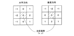
ここで、Sobelフィルタについて説明する。Sobelフィルタでは、ある注目画素位置(x,y)を中心として上下左右の9つの輝度値に対して、図3に図示する水平方向及び垂直方向の係数行列の該当箇所の係数をそれぞれ乗算し、この乗算結果を合計する。この水平方向及び垂直方向の乗算結果が、注目画素位置(x,y)における水平方向及び垂直方向のエッジ勾配dx,dyとなる。このとき、画素位置(x,y)におけるエッジは、図4に図示するようにtanθ=dy/dxを満たす方向θを有し、次式(1)の強さa(x,y)を有するエッジとして求められる。
a(x,y)=√(dx2 +dy2 ) ・・(1)
Here, the Sobel filter will be described. The Sobel filter multiplies nine luminance values in the vertical and horizontal directions around a certain target pixel position (x, y) by the coefficients of the corresponding portions of the horizontal and vertical coefficient matrices shown in FIG. The multiplication results are summed. The multiplication result in the horizontal direction and the vertical direction becomes the edge gradients dx, dy in the horizontal direction and the vertical direction at the target pixel position (x, y). At this time, the edge at the pixel position (x, y) has a direction θ satisfying tan θ = dy / dx as shown in FIG. 4 and has a strength a (x, y) of the following equation (1). Required as an edge.
a (x, y) = √ (dx 2 + dy 2 ) (1)
上述した本実施例では、エッジの検出演算にSobelフィルタを採用したが、Prewittフィルタ、Robertsフィルタなど種々のエッジ検出用フィルタが利用できる。 In the above-described embodiment, the Sobel filter is used for the edge detection calculation, but various edge detection filters such as a Prewitt filter and a Roberts filter can be used.
次に、ステップS10で検出された強さa(x,y)のエッジのうち、エッジの強さが第1の閾値Th1以上であるエッジを抽出する(ステップS20)。閾値Th1は、あらかじめ設定された閾値であるが、検出するエッジの数を制御するために、例えば、数段階から選択できるようにしてもよい。また、閾値Th1は、例えば、肖像写真画像、風景写真画像といった画像の種類に応じて設定することもできる。 Next, from the edges of strength a (x, y) detected in step S10, edges whose edge strength is equal to or greater than the first threshold Th1 are extracted (step S20). The threshold value Th1 is a preset threshold value, but may be selected from, for example, several stages in order to control the number of edges to be detected. The threshold value Th1 can also be set according to the type of image such as a portrait photo image or a landscape photo image.
次に、ステップS20で抽出したエッジ強さa(x,y)≧Th1のエッジについて、エッジの幅を演算する(ステップS30)。具体的には、角度θのエッジについて、0°≦θ<45°の場合は水平方向(dx方向)のエッジであるとし、45°≦θ≦90°の場合は垂直方向(dy方向)のエッジであると見なして、水平方向と垂直方向の2方向についてエッジ幅を演算する。 Next, the edge width is calculated for the edge with the edge strength a (x, y) ≧ Th1 extracted in step S20 (step S30). Specifically, regarding the edge of the angle θ, when 0 ° ≦ θ <45 °, the edge in the horizontal direction (dx direction) is assumed, and when 45 ° ≦ θ ≦ 90 °, the edge in the vertical direction (dy direction) is assumed. Assuming that it is an edge, the edge width is calculated in two directions, the horizontal direction and the vertical direction.
ここで、エッジ幅について、図5により説明する。図5(a)は、写真画像の水平方向(dx方向)の画素位置ごとの輝度値の一例を表すグラフである。これを前述のステップS10のエッジ検出処理を行うことにより、図5(b)に示す輝度差演算値(エッジ強さa(x,y))が得られる。この輝度差演算値のうち、閾値Th1以上となる画素X3ないしX5及びX11,X12が前述のステップS20で抽出される。この抽出された画素X3ないしX5及びX11,X12が水平方向に連続する数を水平方向のエッジ幅として演算する。この例では、図5(c)に示すように、画素X3ないしX5からなるエッジの水平方向の幅は3であり、画素X11,X12からなるエッジの水平方向の幅は2である。垂直方向(dy方向)については図示を省略するが、同様の方法でエッジ幅を演算することができる。 Here, the edge width will be described with reference to FIG. FIG. 5A is a graph showing an example of a luminance value for each pixel position in the horizontal direction (dx direction) of a photographic image. By performing the edge detection process in step S10 described above, a luminance difference calculation value (edge strength a (x, y)) shown in FIG. 5B is obtained. Among the luminance difference calculation values, the pixels X3 to X5 and X11, X12 that are equal to or greater than the threshold Th1 are extracted in the above-described step S20. The number of pixels X3 to X5 and X11, X12 extracted in the horizontal direction is calculated as the horizontal edge width. In this example, as shown in FIG. 5C, the horizontal width of the edge composed of the pixels X3 to X5 is 3, and the horizontal width of the edge composed of the pixels X11 and X12 is 2. Although illustration is omitted for the vertical direction (dy direction), the edge width can be calculated by the same method.
なお、本実施例では、最終的には、ユーザによる画像の合焦の判定を行うことから、合焦情報は、情報の精度よりも演算速度を優先して、任意の方向を水平方向と垂直方向に量子化してエッジ幅を求めた。これに対して、水平x,垂直y方向のエッジ幅dx,dyを求め、
tanθ=dy/dx
としてエッジの角度θを求め、エッジの幅ΔLを、
ΔL=√(dx2 +dy2 )
として求め、角度θ方向の幅ΔLのエッジとして扱い、判断を行なうものとすることもできる。本来、エッジ幅とは、任意の角度θを有するエッジ(dx,dy)が所定の角度θ1の方向に連続する幅である。したがって、例えば、異なる角度θ2,θ3(0°≦θ2<θ3<45°)をもつ隣り合った画素のエッジであっても、本実施例では、連続する水平方向のエッジとして検出してしまう。そこで、さらに高い精度での合焦情報の表示が求められる場合には、エッジの方向θを演算し、あるいはより多くの方向に分類して、その方向ごとにエッジ幅を検出すればよい。また、閾値Th1の設定は、方向θの範囲に応じて異なる値を設定してもよい。
In this embodiment, the user finally determines whether the image is in focus. Therefore, the focus information gives priority to the calculation speed over the accuracy of the information, and any direction is perpendicular to the horizontal direction. The edge width was obtained by quantization in the direction. On the other hand, the edge widths dx and dy in the horizontal x and vertical y directions are obtained,
tan θ = dy / dx
As the edge angle θ, and the edge width ΔL,
ΔL = √ (dx 2 + dy 2 )
And can be treated as an edge having a width ΔL in the angle θ direction and determined. Originally, the edge width is a width in which an edge (dx, dy) having an arbitrary angle θ continues in the direction of a predetermined angle θ1. Therefore, for example, even edges of adjacent pixels having different angles θ2 and θ3 (0 ° ≦ θ2 <θ3 <45 °) are detected as continuous horizontal edges in this embodiment. Therefore, when it is desired to display the focus information with higher accuracy, the edge direction θ may be calculated or classified into more directions, and the edge width may be detected for each direction. The threshold Th1 may be set to a different value depending on the range of the direction θ.
次に、ステップS20で抽出されたエッジ強さが第1の閾値Th1以上のエッジの中から、ステップS30で演算されたエッジ幅が第2の閾値Th2以下であるエッジを抽出する(ステップS40)。本実施例では、前述の通り、ステップS30において水平方向と垂直方向の2方向についてエッジ幅を演算しているので、ステップS40においても水平方向と垂直方向の2方向について閾値Th2との比較を行い、Th2以下のエッジ幅を有するエッジを抽出する。例えば、図5(c)に例示するように、水平方向の画素x3ないしx5で構成されるエッジのエッジ幅は3であり、画素x11,x12で構成されるエッジのエッジ幅は2であり、いずれもエッジ幅が第2の閾値Th2以下であることを満たすため、ステップS40において、画素x3ないしx5のエッジ及び画素x11,x12のエッジが抽出される。なお、閾値Th2の設定は、エッジ幅を検出する方向に応じて異なる値を設定してもよい。 Next, an edge whose edge width calculated in step S30 is equal to or smaller than the second threshold Th2 is extracted from the edges whose edge strength extracted in step S20 is equal to or larger than the first threshold Th1 (step S40). . In the present embodiment, as described above, since the edge width is calculated in the two directions of the horizontal direction and the vertical direction in step S30, the threshold value Th2 is compared in both the horizontal direction and the vertical direction in step S40. , An edge having an edge width equal to or smaller than Th2 is extracted. For example, as illustrated in FIG. 5C, the edge width of the edge composed of the pixels x3 to x5 in the horizontal direction is 3, the edge width of the edge composed of the pixels x11 and x12 is 2, In any case, in order to satisfy that the edge width is equal to or smaller than the second threshold Th2, the edges of the pixels x3 to x5 and the edges of the pixels x11 and x12 are extracted in step S40. The threshold Th2 may be set to a different value depending on the direction in which the edge width is detected.
なお、第2の閾値Th2は、固定値としてもよいが、記録された画像サイズやデジタルスチルカメラ100が備えるトリミング機能によりトリミングされた画像サイズに応じて設定することとしてもよい。具体的には、L版印刷を初期設定として選択する場合には、第2の閾値Th2は、例えば、L版サイズ上で0.5mmに相当する画素数として設定することが経験上適切である。また、第2の閾値Th2は、同一の画像サイズの画像に対して、印刷用紙サイズに応じて設定することとしてもよい。具体的には、所定の画像サイズの画像をA4サイズで印刷する場合には、例えば、入力手段40の操作により印刷用紙サイズメニューの中からA4を選択することで、自動的に第2の閾値Th2を初期設定であるL版サイズ上で0.5mmに相当する画素数から、A4サイズ上で0.3mmに相当する画素数に変更できるものとしてもよい。さらに、第2の閾値Th2は、画像サイズと印刷用紙サイズの組み合わせに応じて設定することとしてもよい。
Note that the second threshold Th2 may be a fixed value, but may be set according to the recorded image size or the image size trimmed by the trimming function provided in the digital
次に、ステップS40で抽出されたエッジの位置に所定の表示を行うことで、視認可能な合焦領域を示す情報として画面上に出力する(ステップS50)。ステップS40で抽出されたエッジは、その幅が所定の値以下の、ある程度シャープなエッジであり、このエッジを有する画素から形成される被写体は、合焦しているものとして考えることができる。したがって、ステップS50では、このエッジの位置を合焦領域として画面上に出力する。本実施例では、エッジの位置の出力表示方法は、フレームメモリ23(図1)に出力されるエッジの位置のみを所定の色で着色した画像データをLCD54(図1)に表示する第1の表示方法と、フレームメモリ21(図1)に出力される写真画像データとフレームメモリ23に出力されるエッジの位置画像データを重畳してLCD54に表示する第2の表示方法を、入力手段40の操作により選択することができるものとした。なお、エッジ位置の着色は、どのような色彩の写真画像データと重畳してもエッジ位置が明確に視認可能となるように数種類の色から選択できるものとした。
Next, by performing a predetermined display at the edge position extracted in step S40, the information is output on the screen as information indicating the in-focus area that is visible (step S50). The edge extracted in step S40 is a somewhat sharp edge whose width is equal to or less than a predetermined value, and the subject formed from the pixels having this edge can be considered to be in focus. Therefore, in step S50, the position of this edge is output on the screen as a focus area. In this embodiment, the edge position output display method is a first method in which image data in which only the edge position output to the frame memory 23 (FIG. 1) is colored with a predetermined color is displayed on the LCD 54 (FIG. 1). A display method and a second display method in which the photographic image data output to the frame memory 21 (FIG. 1) and the edge position image data output to the
次に、合焦の条件に合致するエッジを含む領域、すなわち、ステップS40において抽出されたエッジにより輪郭が形成される被写体が存在する合焦領域を、枠画像を用いて区分された区画としてLCD54に表示する(ステップS60)。具体的には、図6を用いて説明する。図6(a)は、ステップS50において、上述の第2の表示方法により写真画像データとエッジの位置画像データが重畳してLCD54に表示された例である。ハッチングを施した部分は被写体OBを示し、ドット表示した部分はエッジ位置表示FPを示している。ステップS60では、例えば、図6(a)においてエッジ位置表示FPが表示された合焦領域に、図6(b)のように、F1ないしF7の区画の枠FRが、図6(a)で表示された画像と重畳して表示される。本実施例では、合焦領域の区画表示は、写真画像全体の縦横をそれぞれ4分割した16区画を最大として、このうち合焦領域を含む区画のみ枠画像を表示するものとしたが、LCD54や写真画像の画素数に応じて他の区画数を設定してもよい。また、区画数及び区画位置は、合焦部分の大きさやLCD54の画素数などに応じて自動的に設定されるものとしてもよい。もとより、LCD54の画素数に応じて予め決められた区画数で、写真画像全体を区画表示するものとしてもよい。
Next, the area including the edge that matches the in-focus condition, that is, the in-focus area in which the subject whose outline is formed by the edge extracted in step S40 is present as the section partitioned using the frame image. (Step S60). Specifically, this will be described with reference to FIG. FIG. 6A shows an example in which the photographic image data and the edge position image data are superimposed and displayed on the
次に、ステップS60において表示された区画のうち、1の区画をユーザが指定した時、当該1の区画に該当する写真画像を所望の倍率に拡大表示する(ステップS70)。本実施例では、ステップS60において表示された区画は、F1ないしF7の7区画である。このうち、ユーザが、例えば、入力手段40によるカーソル移動で区画F3を指定した時、区画F3に該当する写真画像は図6(c)に示すようにLCD54の画面全体に拡大表示される。さらに、拡大倍率は、あらかじめ設定された所定倍率、例えば、ピクセル等倍を100%として、100%、75%、50%、25%の選択肢の中から、ユーザが入力手段40を用いてカーソル移動により所望の倍率を選択すれば、変更することができる。この場合、指定された拡大倍率で区画F3に該当する写真画像がLCD54に表示され、当該拡大写真画像がLCD54よりも大きい場合には、ユーザは、カーソル移動によりLCD54の表示箇所を移動させることができる。
Next, when the user designates one of the sections displayed in step S60, the photograph image corresponding to the one section is enlarged and displayed at a desired magnification (step S70). In the present embodiment, the sections displayed in step S60 are seven sections F1 to F7. Among these, for example, when the user designates the section F3 by moving the cursor with the input means 40, the photographic image corresponding to the section F3 is enlarged and displayed on the entire screen of the
かかる構成のデジタルスチルカメラ100は、まず、写真画像のどの部分が合焦領域であるかを装置の判定結果により視覚的に容易に概略確認でき、さらに、当該合焦領域をLCD54に所望の倍率に拡大表示させてユーザ自ら視覚的に確認することで、確実に写真画像の合焦状況を確認することができる。
The digital
(2)第2実施例:
次に、本発明の第2実施例について説明する。第2実施例では、第1実施例と同一のハードウェア構成を採用しており、以下に声明するエッジの検出処理のみが異なっている。具体的には、図6に示した第1実施例のステップS10ないしS40の処理に代えて、図7のフローチャートに示す処理(S110ないしS140)を実行する。合焦情報の視覚化処理が開始されると、第2実施例では、まず所定方向に並んだ画素の輝度値の差分を検出する処理を行なう(ステップS110)。第2実施例では、水平方向と垂直方向の両方向について、輝度値の差分を演算している。図8では、説明を簡略化して水平方向について例示している。図8(A)は、各画素の輝度値Zを例示し、図8(B)は、この場合の輝度値の差分ΔZを例示している。なお、第1実施例では、輝度の変化量は絶対値で求めたが、第2実施例では、輝度値の差分ΔZは、符号付きの値として演算している。また、差分ΔZは、画素間について逐次演算されるので、必要に応じて、今回着目している差分をΔZ(n)として表記し、着目画素の一つ前の画素についての差分をΔZ(n−1)として表記するものとする。
(2) Second embodiment:
Next, a second embodiment of the present invention will be described. In the second embodiment, the same hardware configuration as that of the first embodiment is adopted, and only the edge detection process described below is different. Specifically, instead of the processing of steps S10 to S40 of the first embodiment shown in FIG. 6, processing (S110 to S140) shown in the flowchart of FIG. 7 is executed. When the focusing information visualization process is started, in the second embodiment, first, a process of detecting a difference between luminance values of pixels arranged in a predetermined direction is performed (step S110). In the second embodiment, the difference in luminance value is calculated in both the horizontal direction and the vertical direction. FIG. 8 illustrates the horizontal direction by simplifying the description. FIG. 8A illustrates the luminance value Z of each pixel, and FIG. 8B illustrates the luminance value difference ΔZ in this case. In the first embodiment, the amount of change in luminance is obtained as an absolute value. In the second embodiment, the difference ΔZ in luminance value is calculated as a signed value. Further, since the difference ΔZ is sequentially calculated between pixels, if necessary, the difference focused on this time is expressed as ΔZ (n), and the difference for the pixel immediately before the focused pixel is expressed as ΔZ (n -1).
次に、着目している画素について演算した輝度値の差分ΔZ(n)の符号が一つの前の画素について演算した求めた輝度値の差分ΔZ(n−1)の符号と同一か否かの処理を行なう(ステップS112)。両者が一致していれば(ステップS112:「YES」)、エッジは継続していると判断し、輝度値の差分ΔZ(n)を累積した累積値SZを求める処理を行なう(ステップS114)。具体的には、エッジが開始されたと判断したときに0にリセットされる累積しSZに、今回の差分ΔZ(n)を加算するのである(SZ←SZ+ΔZ(n))。累積値SZを求めた後、ステップS116で、着目画素の位置を所定の方向に1だけ進め(n←n+1)、上記処理を継続する(ステップS110ないしS116)。 Next, whether the sign of the luminance value difference ΔZ (n) calculated for the pixel of interest is the same as the sign of the calculated luminance value difference ΔZ (n−1) calculated for the previous pixel Processing is performed (step S112). If the two match (step S112: “YES”), it is determined that the edge continues, and a process of obtaining a cumulative value SZ obtained by accumulating the luminance value difference ΔZ (n) is performed (step S114). Specifically, the current difference ΔZ (n) is added to the accumulated SZ that is reset to 0 when it is determined that the edge has started (SZ ← SZ + ΔZ (n)). After obtaining the accumulated value SZ, in step S116, the position of the pixel of interest is advanced by 1 in a predetermined direction (n ← n + 1), and the above processing is continued (steps S110 to S116).
上記の処理を繰り返すうちに、着目している画素について演算した輝度値の差分ΔZ(n)の符号が一つの前の画素について演算した求めた輝度値の差分ΔZ(n−1)の符号と同一でないと判断されると(ステップS112:「NO」)、そこまで求めて来た累積値SZの絶対値|SZ|が、予め定めた閾値Th1より大きいか否かの判断を行なう(ステップS120)。この判断の様子を図8(B)に示した。累積値SZの絶対値が閾値Th1より大きいと判断されれば(ステップS120:「YES」)、合焦について判定すべきエッジがある可能性があると考えられるので、次にエッジの幅Weを求める処理を行なう(ステップS130)。エッジの幅は、ステップS110で求めた輝度値の差分ΔZが同一符号の間の画素数として設定される。 While repeating the above process, the sign of the difference ΔZ (n) in the luminance value calculated for the pixel of interest is the sign of the difference ΔZ (n−1) in the calculated luminance value calculated for the previous pixel. If it is determined that they are not identical (step S112: “NO”), it is determined whether or not the absolute value | SZ | of the accumulated value SZ obtained so far is larger than a predetermined threshold Th1 (step S120). ). The state of this determination is shown in FIG. If it is determined that the absolute value of the cumulative value SZ is larger than the threshold value Th1 (step S120: “YES”), it is considered that there may be an edge to be determined for focusing. The requested process is performed (step S130). The edge width is set as the number of pixels in which the difference ΔZ in luminance values obtained in step S110 is between the same signs.
エッジの幅Weを求めた後、この幅Weが、予め定めた閾値Th2以下か否かの判断を行ない(ステップS135)、エッジの幅Weが閾値Th2以下であれば、これらの画素は合焦の状態にあるとして、そのエッジを登録する処理を行なう(ステップS140)。その後、累積値SZを値0にリセットする処理(ステップS143)を行なう。他方、ステップS120またはS135での判断が「NO」であれば、合焦の状態にあると判断できるエッジではないとして、何の処理も行なわず、ステップS143で累積値SZをリセットする処理に移行する。これらの処理により、図8に示したように、隣接画素の輝度値の差分ΔZの符号が隣接画素間で同一でなくなったときに、エッジの有無を、この差分ΔZの累積値SZの大きさで判定し、判定の如何に関わらず、累積値SZを次の判定に備えて、値0にリセットすることになる。 After obtaining the edge width We, it is determined whether the width We is equal to or smaller than a predetermined threshold Th2 (step S135). If the edge width We is equal to or smaller than the threshold Th2, these pixels are in focus. In step S140, the edge is registered. Thereafter, a process of resetting the accumulated value SZ to the value 0 (step S143) is performed. On the other hand, if the determination in step S120 or S135 is “NO”, it is determined that the edge is not in an in-focus state, and no processing is performed, and the process proceeds to processing for resetting the accumulated value SZ in step S143. To do. As a result of these processes, as shown in FIG. 8, when the signs of the difference ΔZ in luminance values of adjacent pixels are not the same between adjacent pixels, the presence / absence of an edge is determined based on the cumulative value SZ of the difference ΔZ. Regardless of the determination, the accumulated value SZ is reset to 0 in preparation for the next determination.
そこで、上記の一連の処理により一つのエッジについての判定が完了すると、総ての画素についての判断が終わったかを判定し(ステップS145)、終わっていなければ、ステップS110に戻って、上記の処理(ステップS110ないしS143)の処理を繰り返す。総ての画素について上記の判断が終わっていれば(ステップS145:「YES」)、第1実施例の図2に示したフローチャートのステップS50以下の処理に移行する。以後の処理については、第1実施例と同様なので、説明は省略するが、ステップS140で抽出し登録しておいたエッジを順次読み出して、エッジが存在する領域が合焦の領域であるとして、これを死人可能に画像と共に表示するのである。 Therefore, when the determination for one edge is completed through the above-described series of processing, it is determined whether all the pixels have been determined (step S145). If not, the processing returns to step S110, and the above processing is performed. The processing of (Steps S110 to S143) is repeated. If the above determination is completed for all the pixels (step S145: “YES”), the process proceeds to the processing of step S50 and subsequent steps in the flowchart shown in FIG. Since the subsequent processing is the same as in the first embodiment, a description thereof will be omitted, but the edges extracted and registered in step S140 are sequentially read out, and the area where the edges are present is the in-focus area. This is displayed along with the image so that it can be dead.
以上説明した第2実施例によれば、エッジの抽出を、隣接画素の輝度値の差分ΔZの符号が隣接画素間で同一でなくなったときに、この差分ΔZの累積値SZの大きさを判定することにより行なっている。したがって、画素の並びがエッジを構成しているとき、途中に差分ΔZが小さい画素間が存在したとき、その前後を別々のエッジと判定することがない。他方、全体の傾向としては、画素の輝度値が漸増または漸減していても、途中で差分ΔZが値0になるか、その符号が変更されれば、そこでエッジが分かれていると判断するので、エッジの存在領域を見誤る可能性が低減される。この結果、ノイズなどが存在しても、合焦の情報として扱うべきエッジの存在を的確に判定することができる。 According to the second embodiment described above, the edge is extracted by determining the magnitude of the accumulated value SZ of the difference ΔZ when the sign of the luminance value difference ΔZ between adjacent pixels is not the same between adjacent pixels. It is done by doing. Therefore, when the arrangement of pixels constitutes an edge and there is an inter-pixel having a small difference ΔZ in the middle, the front and rear are not determined as separate edges. On the other hand, as an overall tendency, even if the luminance value of the pixel gradually increases or decreases, if the difference ΔZ becomes 0 or changes its sign in the middle, it is determined that the edge is divided there. The possibility of mistaking the edge existence area is reduced. As a result, even if there is noise or the like, it is possible to accurately determine the presence of an edge that should be handled as focusing information.
(3)第3実施例:
次に本発明の第3実施例について説明する。第3実施例も、第1,第2実施例と同様のハードウェア構成により実現される。第3実施例では、第1実施例における表示方法のみ異なっている。第1実施例では、図2のステップS50に示したように、合焦と判断できるエッジを抽出したら、このエッジの位置を視認可能に、LCD54上に表示している。この表示の際、第1実施例では、図6(a)に示したように、エッジ位置表示FPを、エッジが抽出された位置において、元画像に重ねている。これに対して、第3実施例では、図9にステップS150として示したように、画面全体から、合焦画像と判断できるエッジを抽出した後、このエッジの位置に対応する画像を処理して表示している。
(3) Third embodiment:
Next, a third embodiment of the present invention will be described. The third embodiment is also realized by the same hardware configuration as the first and second embodiments. In the third embodiment, only the display method in the first embodiment is different. In the first embodiment, as shown in step S50 of FIG. 2, when an edge that can be determined to be in focus is extracted, the position of this edge is displayed on the
この様子を、図6(a)に対応させて、図10に示した。図示するように、第3実施例では、抽出したエッジの位置の画像を白塗りに処理して、LCD54上に表示している。図10の例では花の位置に合焦しており、ここが白塗りの領域WPとして表示される。この場合、元の画像は確認できない状態になるが、逆に合焦の位置を明確に理解することができるという利点が得られる。なお、合焦の程度を複数の段階に分け、完全に合焦していると判断された領域を白塗りの領域WPとし、それよりは少しぼけた、しかし焦点の合っていると判断された領域をグレーに塗りつぶした領域GPとして、表示してもよい。図10では、手前の葉の表示領域が、2番目に合焦した領域として、グレーに塗りつぶした領域GPとして表示されている。もとより、塗りつぶしの色は、どのような色に設定することも差し支えない。また、各領域WP,GP内に、文字で「合焦領域」や「第2合焦領域」などの表示を添えることも差し支えない。
This state is shown in FIG. 10 corresponding to FIG. As shown in the figure, in the third embodiment, the extracted image of the edge position is processed into white and displayed on the
この実施例では、合焦の位置を白塗りとしたが、その他の画像処理を施すことも可能である。その他の画像処理としては、
(A)抽出されたエッジの位置の画素(以下、合焦部分という)、すなわち合焦していると判定された画素をカラー表示し、抽出されたエッジの位置以外の画素(以下、非合焦部分という)、すなわち合焦しているかどうか分からない画素を白黒表示(または非表示)とする方法、
(B)合焦部分と非合焦部分の写真画像を所定の色で補色表示する方法、
(C)合焦部分の写真画像のみを明度変更する方法、
(D)合焦部分の写真画像のみをネガポジ反転または輝度反転表示する方法、
(E)合焦部分の写真画像のみを点滅表示する方法、
(F)これらを組み合わせた方法、
(G)上述の合焦部分と非合焦部分の処理を逆転した方法、
(H)上記(A)ないし(F)の画像処理を施した画像と元画像とを所定時間毎に交互に表示する方法、
など種々の方法が可能である。これらの表示方法は、入力手段40により選択することができるものとしてもよい。なお、本変形例の場合、ステップS70において、ユーザの区画指定により拡大表示する写真画像は、上記の画像処理後の写真画像ではなく、画像処理前の元の写真画像としたが、処理後の写真画像としても良く、入力手段40による指示によりいずれかを選択して表示するものとしても良い。
In this embodiment, the focus position is white, but other image processing can also be performed. As other image processing,
(A) A pixel at an extracted edge position (hereinafter referred to as an in-focus portion), that is, a pixel determined to be in focus is displayed in color, and a pixel other than the extracted edge position (hereinafter referred to as an in-focus position) is displayed. A method of making a pixel in black and white display (or non-display) that does not know whether it is in focus,
(B) A method of displaying a photographic image of an in-focus portion and a non-focus portion in a complementary color with a predetermined color,
(C) a method of changing the brightness of only the photograph image of the in-focus portion,
(D) a method of negative-positive reversal or luminance reversal display of only the photographic image of the in-focus portion,
(E) A method of blinking and displaying only a photographic image of the in-focus portion,
(F) a method combining these,
(G) A method in which the processing of the in-focus portion and the out-of-focus portion described above is reversed,
(H) A method of alternately displaying the image subjected to the image processing of (A) to (F) and the original image at predetermined time intervals,
Various methods are possible. These display methods may be selected by the input means 40. In this modification, in step S70, the photographic image to be enlarged and displayed by the user's section designation is not the photographic image after the image processing described above, but the original photographic image before the image processing. It may be a photographic image, or may be selected and displayed by an instruction from the input means 40.
この結果、合焦部分あるいは非合焦部分を強調して表示することができ、ユーザは、どのような色彩の写真画像であっても分かりやすく合焦判定位置を確認することができる。 As a result, the in-focus portion or the out-of-focus portion can be displayed with emphasis, and the user can confirm the focus determination position in an easy-to-understand manner regardless of the color of the photographic image.
(4)変形例1:
実施例では、ステップS40で抽出された第2の閾値Th2以下のエッジについて、ステップS50において当該エッジの位置に所定の表示を行うことで視認可能な合焦情報として画面上に出力したが、変形例1では、エッジの位置にエッジ幅に応じた表示を行うことで視認可能な合焦情報として出力することができる。
(4) Modification 1:
In the embodiment, the edge of the second threshold value Th2 or less extracted in step S40 is output on the screen as in-focus information that can be visually recognized by performing a predetermined display at the position of the edge in step S50. In Example 1, it is possible to output focus information that can be visually recognized by performing display according to the edge width at the edge position.
例えば、ステップS50でエッジ位置を所定の色で着色表示する場合において、ステップS40で抽出された閾値Th2以下のエッジ幅wを有する任意のエッジについて、1<Th2(1)<Th2(2)<Th2を満たす中間閾値Th2(1),Th2(2)を用いて、エッジ幅wが1≦w<Th2(1)の範囲にある場合は当該エッジ位置を赤色で着色し、Th2(1)≦w<Th2(2)の範囲にある場合は黄色で着色し、Th2(2)≦w≦Th2の範囲にある場合には青色で着色するといったように、エッジ幅に応じて色分け表示することができる。また、色分けの代わりに、同一系色で明度を変えて表示してもよい。さらに、エッジ幅の値の変化に合わせてグラデーション表示を行ってもよい。 For example, in the case where the edge position is displayed in a predetermined color in step S50, 1 <Th2 (1) <Th2 (2) <for any edge having an edge width w equal to or smaller than the threshold Th2 extracted in step S40. If the edge width w is in the range of 1 ≦ w <Th2 (1) using the intermediate threshold values Th2 (1) and Th2 (2) satisfying Th2, the edge position is colored in red, and Th2 (1) ≦ Colors are displayed according to the edge width, such as yellow when the range is w <Th2 (2) and blue when the range is Th2 (2) ≦ w ≦ Th2. it can. Further, instead of color coding, the brightness may be displayed in the same system color. Further, gradation display may be performed in accordance with the change of the edge width value.
なお、エッジ幅と合焦状況の関係については、エッジ幅が小さいほど、シャープなエッジであり、当該箇所の合焦の程度が高いと考えることができる。 As for the relationship between the edge width and the in-focus state, it can be considered that the smaller the edge width, the sharper the edge and the higher the degree of in-focus.
この結果、写真画像の合焦状況について、合焦の位置のみならず合焦の程度まで画面表示されることから、ユーザは、より詳細に合焦状況を概略確認した上で、所望の領域をLCD54に拡大表示させて確認することで、効率的に写真画像の合焦状況を確認することができる。
As a result, the in-focus state of the photographic image is displayed on the screen not only to the in-focus position but also to the in-focus level, so the user can check the in-focus state in more detail and then select the desired area. By confirming the enlarged display on the
(5)変形例2:
実施例では、ステップS20において、エッジ強さa(x,y)に対して第1の閾値を設けてエッジを抽出し、ステップS30において、エッジの方向θにより当該エッジを水平方向、あるいは垂直方向と見なして、それぞれの方向についてエッジ幅を演算したが、変形例3として、以下の方法によりステップS20のエッジ抽出及びステップS30のエッジ幅の演算を行うこともできる。
(5) Modification 2:
In the embodiment, in step S20, an edge is extracted by providing a first threshold value with respect to the edge strength a (x, y), and in step S30, the edge is determined in the horizontal direction or the vertical direction depending on the edge direction θ. However, as a third modification, the edge extraction in step S20 and the edge width in step S30 can be calculated by the following method.
まず、ステップS20において、水平方向(dx方向)のエッジ強さax(x,y)が、水平方向の第1の閾値Th1x以上となる、すなわちax(x,y)=|dx|≧Th1xとなるエッジと、垂直方向(dy方向)のエッジ強さay(x,y)が、垂直方向の第1の閾値Th1y以上となる、すなわち、ay(x,y)=|dy|≧Th1yとなるエッジを抽出する。そして、ステップS30において、ステップS20で抽出したエッジについて水平方向、垂直方向ごとにエッジ幅を演算する。 First, in step S20, the edge strength ax (x, y) in the horizontal direction (dx direction) is not less than the first threshold Th1x in the horizontal direction, that is, ax (x, y) = | dx | ≧ Th1x. And the edge strength ay (x, y) in the vertical direction (dy direction) are equal to or greater than the first threshold Th1y in the vertical direction, that is, ay (x, y) = | dy | ≧ Th1y. Extract edges. In step S30, the edge width is calculated for each of the horizontal direction and the vertical direction for the edge extracted in step S20.
この場合、演算を簡略化することができ、短時間で水平方向及び鉛直方向のエッジ幅を演算することができる。なお、本変形例では、実施例に合わせて、水平方向と垂直方向についてエッジ幅を演算したが、勿論、これ以外の方向についてエッジ幅を検出してもよい。 In this case, the calculation can be simplified and the horizontal and vertical edge widths can be calculated in a short time. In this modification, the edge width is calculated in the horizontal direction and the vertical direction according to the embodiment, but of course, the edge width may be detected in other directions.
(6)変形例3:
上述した第1実施例では、エッジ抽出の際の閾値Th2を、印刷用紙サイズの設定に応じて変更した。こうした印刷用紙サイズの設定・変更は、印刷用紙サイズメニューの中から、「A4」といったサイズを選択するものとして説明したが、図11に示すように、アイコンを用いて設定するものとしても良い。図11の例では、第2の閾値Th2を設定するプリセットの画面を、入力手段40の操作により呼び出したとき、選択可能な用紙サイズをアイコン201ないし204として画面上に表示している。アイコン201ないし204には、印刷用紙サイズを示す「A3」「A4」「2L」「L」といった表示が付与されている。なお、「L」とは、写真印刷におけるL版のサイズを意味している。
(6) Modification 3:
In the first embodiment described above, the threshold value Th2 for edge extraction is changed according to the print paper size setting. Such setting / changing of the printing paper size has been described as selecting a size such as “A4” from the printing paper size menu, but it may be set using an icon as shown in FIG. In the example of FIG. 11, when a preset screen for setting the second threshold Th <b> 2 is called by operating the input means 40, selectable paper sizes are displayed on the screen as
この例では、LCD54に表示されたアイコンは、入力手段40に設けられたカーソルカーを操作することにより順次選択状態となり、「決定」ボタンを押すことで、設定が完了する。もとより、LCD54の表面にタッチパネルを設け、LCD54上に表示されたいずれかのアイコンを、指やスタイラスペンで直接タップして選択するものとしても良い。この場合、指などアイコンをタップすると、その印刷用紙サイズのアイコンの表示が反転され、いずれの印刷用紙サイズが選択されたかを明示すると共に選択を完了する。図11では、アイコン204が選択されている様子を示した。
In this example, the icons displayed on the
印刷用紙サイズに対応したアイコンを選択することにより、印刷用紙サイズが変更されると、抽出すべきエッジの幅が変更されるので、いずれかのアイコンを選択するたびに、その印刷用紙サイズに基づいて演算された閾値Th2を用いて、エッジ抽出の判断をやり直し、LCD54上の印刷画像の表示を変更することも好適である。第1実施例では、合焦の情報を示すエッジの位置表示FPに着色して、合焦の領域が分かるようにした。アイコンを選択する度に、アイコンの表示は残したまま、印刷画像の着色表示が修正されると、使用者は、印刷する用紙の大きさから見て、どの程度の範囲がくっきり印刷され、あるいはどの程度の範囲がぼやけて印刷されるかを判断することができる。LCD54上に表示されたアイコンを選択するだけなので、こうした合焦の情報の確認を簡単に行なうことができ、好適である。なお、この例では、アイコンの大きさは印刷用紙サイズに合わせた大小としたが、均等な大きさのアイコンとしても良い。こうしたアイコンの表示は、入力手段40を操作することにより終了し、印刷用紙サイズのプリセットモードは終了する。
If the icon corresponding to the print paper size is selected and the print paper size is changed, the width of the edge to be extracted will be changed. Therefore, each time an icon is selected, it will be based on the print paper size. It is also preferable to redo the edge extraction determination using the threshold Th2 calculated in this way and change the display of the print image on the
以上本発明の幾つかの実施例、変形例について説明したが、本発明はこうした実施例に限られるものではなく、本発明の要旨を脱しない範囲において、種々なる態様で実施できることは勿論である。例えば、本発明の合焦情報視覚化装置は、デジタルスチルカメラに限らず、液晶ディスプレイを搭載したプリンタ、カメラ付携帯電話、写真画像を拡大確認するためのフォトビューアなどに搭載することができる。もとより、コンピュータに搭載して、コンピュータのモニタで写真画像を取捨選択する場合にも採用可能である。また、合焦情報視覚化方法、合焦情報視覚化プログラム、またはプログラムを記録したコンピュータで読み取り可能な記録媒体等の形態でも実現することができる。 Although several embodiments and modifications of the present invention have been described above, the present invention is not limited to these embodiments, and it goes without saying that the present invention can be implemented in various modes without departing from the gist of the present invention. . For example, the focus information visualization apparatus of the present invention can be mounted not only on a digital still camera but also on a printer equipped with a liquid crystal display, a mobile phone with a camera, a photo viewer for enlarging a photographic image, and the like. Of course, the present invention can also be employed when the photographic image is selected on a computer monitor by being mounted on a computer. Further, the present invention can be realized in the form of a focus information visualization method, a focus information visualization program, or a computer-readable recording medium on which the program is recorded.
10…光学系
14…画像データ作成部
21,22,23…フレームメモリ
30…制御部
32…CPU
40…入力手段
60…画像データ出力部
70…記録媒体制御部
72…記録媒体
73…拡張記録媒体
100…デジタルスチルカメラ
dx,dy…エッジ勾配
θ…角度
Th1,Th2…閾値
x3〜x5,x11,x12…画素
OB…被写体
FP…エッジ位置表示
FR…枠
F1〜F7…区画
DESCRIPTION OF
DESCRIPTION OF
Claims (14)
前記写真画像の各画素の輝度情報に基づいて、該画像に存在するエッジのうち、合焦の条件に合致するエッジを抽出するエッジ抽出手段と、
該抽出されたエッジを用いて、合焦の情報を、前記画面上に視認可能に出力する合焦情報出力手段と
を備えた合焦情報視覚化装置。 A focusing information visualization device that visualizes focusing information of a photographic image on a screen,
Based on the luminance information of each pixel of the photographic image, an edge extracting means for extracting an edge that matches the focusing condition among edges existing in the image;
A focus information visualization device comprising: focus information output means for outputting focus information so as to be visible on the screen using the extracted edge.
前記エッジ抽出手段は、
前記写真画像の各画素の輝度情報に基づいて該写真画像の各位置におけるエッジを検出するエッジ検出手段と、
前記検出されたエッジから第1の閾値以上の強さを有するエッジを抽出する第1のエッジ抽出手段と、
前記抽出されたエッジのエッジ幅を演算するエッジ幅演算手段と、
前記演算されたエッジ幅が第2の閾値以下であるエッジを抽出する第2のエッジ抽出手段と
を備えた合焦情報視覚化装置。 The focusing information visualization device according to claim 1,
The edge extraction means includes
Edge detecting means for detecting an edge at each position of the photographic image based on luminance information of each pixel of the photographic image;
First edge extraction means for extracting an edge having a strength equal to or greater than a first threshold from the detected edge;
Edge width calculating means for calculating the edge width of the extracted edge;
A focus information visualization device comprising: second edge extraction means for extracting an edge whose calculated edge width is equal to or smaller than a second threshold value.
前記エッジ検出手段は、前記写真画像を構成する各画素について、所定方向に並んだ画素間の輝度の差分の累積値が漸増または漸減している範囲をエッジとして検出する手段であり、
前記第1のエッジ抽出手段は、前記累積値が漸増または漸減した結果、該累積値の絶対値が所定の閾値を超えたとき、前記エッジの抽出を行なう手段であり、
前記エッジ幅演算手段は、前記抽出されたエッジの幅を、前記漸増または漸減の全期間として演算する手段である
合焦情報視覚化装置。 The focusing information visualization device according to claim 2,
The edge detection means is means for detecting, as an edge, a range in which the cumulative value of the luminance difference between pixels arranged in a predetermined direction is gradually increased or gradually reduced for each pixel constituting the photographic image,
The first edge extraction means is means for extracting the edge when the absolute value of the cumulative value exceeds a predetermined threshold as a result of the cumulative value gradually increasing or decreasing.
The focus information visualizing device, wherein the edge width calculating means is a means for calculating the width of the extracted edge as a whole period of the gradual increase or decrease.
前記合焦情報出力手段は、前記合焦の情報を抽出した前記画面上の位置の元画像を処理することにより表示の態様を変更して、前記合焦の情報の出力を行なう
合焦情報視覚化装置。 The focusing information visualization device according to claim 1,
The focus information output means changes the display mode by processing the original image at the position on the screen from which the focus information is extracted, and outputs the focus information. Device.
前記合焦情報出力手段は、前記表示の態様の変更を、合焦の情報を抽出した位置の原画像を、
明度が所定以上のグレー画像に変更すること、
該グレー画像と元画像とを交互に表示する態様に変更すること、
元画像をネガポジ反転した画像に変更すること、
前記エッジが前記合焦の条件に合致する度合いに応じて異なる2以上の表示の態様に変更すること
のうちのいずれか一つの態様により行なう合焦情報視覚化装置。 The in-focus information visualization apparatus according to claim 5,
The in-focus information output means changes the display mode, the original image at the position where the in-focus information is extracted,
Changing to a gray image with a lightness above a certain level,
Changing to a mode of alternately displaying the gray image and the original image;
Changing the original image to a negative-positive inverted image,
A focus information visualization apparatus that performs the focus information visualization according to any one of the two or more different display modes according to the degree to which the edge matches the focusing condition.
前記合焦情報出力手段は、
前記合焦の条件に合致するエッジを含む少なくとも1の領域を、枠画像を用いて区分された区画として前記画面上に表示する手段と、
前記区画のうち1の区画がユーザ操作により指定された時、該指定された区画に属する前記写真画像を所望の倍率に拡大して前記画面上に出力する手段と
を備えた合焦情報視覚化装置。 A focusing information visualization device according to any one of claims 1 to 9,
The focusing information output means includes
Means for displaying on the screen at least one area including an edge that matches the focusing condition as a section partitioned using a frame image;
When one of the sections is designated by a user operation, the focus information visualization comprises: means for enlarging the photographic image belonging to the designated section to a desired magnification and outputting it on the screen. apparatus.
前記写真画像を印刷する印刷媒体の大きさを指定する印刷媒体指定手段を備え、
前記エッジ抽出手段は、前記指定された印刷媒体の大きさと、前記写真画像大きさとに基づいて、前記合焦の条件に合致するとして検出するエッジの条件を定め、該条件に基づいて、前記エッジの抽出を行なう
合焦情報視覚化装置。 The in-focus information visualizing device according to any one of claims 1 to 10,
A printing medium designating unit for designating a size of a printing medium on which the photographic image is printed;
The edge extracting means determines an edge condition to be detected as matching the focusing condition based on the specified print medium size and the photographic image size, and based on the condition, the edge Focusing information visualization device that performs extraction.
前記写真画像の各画素の輝度情報に基づいて、該画像に存在するエッジのうち、合焦の条件に合致するエッジを抽出するエッジ抽出工程と、
該抽出されたエッジを用いて、合焦の情報を、前記画面上に視認可能に出力する合焦情報出力工程と
を備えた合焦情報視覚化方法。 A focusing information visualization method for visualizing focusing information of a photographic image on a screen,
Based on the luminance information of each pixel of the photographic image, an edge extraction step of extracting an edge that matches the focusing condition among edges existing in the image;
A focus information visualization method comprising: a focus information output step of outputting focus information so as to be visible on the screen using the extracted edge.
前記写真画像の各画素の輝度情報に基づいて、該画像に存在するエッジのうち、合焦の条件に合致するエッジを抽出するエッジ抽出機能と、
該抽出されたエッジを用いて、合焦の情報を、前記画面上に視認可能に出力する合焦情報出力機能と
をコンピュータに実現させるためのプログラム。 A focusing information visualization program for visualizing focusing information of a photographic image on a screen,
Based on the luminance information of each pixel of the photographic image, an edge extraction function that extracts an edge that matches the focusing condition among edges existing in the image;
A program for causing a computer to realize a focusing information output function for outputting focusing information so as to be visible on the screen using the extracted edge.
Priority Applications (2)
| Application Number | Priority Date | Filing Date | Title |
|---|---|---|---|
| JP2007178811A JP2008072696A (en) | 2006-08-14 | 2007-07-06 | Focusing information visualization device, and corresponding method, program and recording medium |
| US11/891,977 US7978247B2 (en) | 2006-08-14 | 2007-08-13 | Focusing information visualization device, and corresponding method, program and recording medium |
Applications Claiming Priority (2)
| Application Number | Priority Date | Filing Date | Title |
|---|---|---|---|
| JP2006221110 | 2006-08-14 | ||
| JP2007178811A JP2008072696A (en) | 2006-08-14 | 2007-07-06 | Focusing information visualization device, and corresponding method, program and recording medium |
Related Child Applications (1)
| Application Number | Title | Priority Date | Filing Date |
|---|---|---|---|
| JP2008254019A Division JP2009044757A (en) | 2006-08-14 | 2008-09-30 | Focusing information visualization device, and corresponding method, program and recording medium |
Publications (2)
| Publication Number | Publication Date |
|---|---|
| JP2008072696A true JP2008072696A (en) | 2008-03-27 |
| JP2008072696A5 JP2008072696A5 (en) | 2009-10-08 |
Family
ID=39050341
Family Applications (1)
| Application Number | Title | Priority Date | Filing Date |
|---|---|---|---|
| JP2007178811A Withdrawn JP2008072696A (en) | 2006-08-14 | 2007-07-06 | Focusing information visualization device, and corresponding method, program and recording medium |
Country Status (2)
| Country | Link |
|---|---|
| US (1) | US7978247B2 (en) |
| JP (1) | JP2008072696A (en) |
Cited By (6)
| Publication number | Priority date | Publication date | Assignee | Title |
|---|---|---|---|---|
| JP2011242796A (en) * | 2011-07-22 | 2011-12-01 | Casio Comput Co Ltd | Imaging device, focusing method and program |
| US8717490B2 (en) | 2009-06-19 | 2014-05-06 | Casio Computer Co., Ltd | Imaging apparatus, focusing method, and computer-readable recording medium recording program |
| JP2014519052A (en) * | 2011-05-06 | 2014-08-07 | レッド.コム,インコーポレイテッド | Focusing support system and method |
| JP2015022085A (en) * | 2013-07-18 | 2015-02-02 | 株式会社 日立産業制御ソリューションズ | Imaging device, imaging method, and imaging system |
| US9692958B2 (en) | 2006-11-20 | 2017-06-27 | Red.Com, Inc. | Focus assist system and method |
| US9690168B2 (en) | 2006-11-20 | 2017-06-27 | Red.Com, Inc. | Focus assist system and method |
Families Citing this family (16)
| Publication number | Priority date | Publication date | Assignee | Title |
|---|---|---|---|---|
| US8264591B2 (en) * | 2007-10-22 | 2012-09-11 | Candela Microsystems (S) Pte. Ltd. | Method and system for generating focus signal |
| TW200930040A (en) * | 2007-12-19 | 2009-07-01 | Altek Corp | Gradient mirror processing method for digital images |
| CN101345825B (en) * | 2008-01-24 | 2010-06-02 | 华硕电脑股份有限公司 | Method for adjusting blurred image |
| JP5163257B2 (en) * | 2008-04-23 | 2013-03-13 | ソニー株式会社 | Imaging device |
| WO2010061352A2 (en) * | 2008-11-26 | 2010-06-03 | Hiok Nam Tay | Auto-focus image system |
| KR101607295B1 (en) * | 2009-07-31 | 2016-04-11 | 엘지전자 주식회사 | Method and apparatus for generating a compressed file, camera module associated with it, and terminal having the camera module |
| JP2011091602A (en) * | 2009-10-22 | 2011-05-06 | Canon Inc | Image display device, imaging apparatus and method for displaying image |
| US8457431B2 (en) * | 2009-12-07 | 2013-06-04 | Hiok Nam Tay | Auto-focus image system |
| US8724009B2 (en) * | 2010-05-05 | 2014-05-13 | Hiok Nam Tay | Auto-focus image system |
| CN102948142B (en) * | 2010-05-26 | 2016-05-25 | 郑苍隆 | Auto-focus image system |
| US9065999B2 (en) | 2011-03-24 | 2015-06-23 | Hiok Nam Tay | Method and apparatus for evaluating sharpness of image |
| JP6169366B2 (en) * | 2013-02-08 | 2017-07-26 | 株式会社メガチップス | Object detection device, program, and integrated circuit |
| JP6094359B2 (en) * | 2013-04-23 | 2017-03-15 | ソニー株式会社 | Image processing apparatus, image processing method, and program |
| US9886766B2 (en) * | 2013-08-16 | 2018-02-06 | Samsung Electronics Co., Ltd | Electronic device and method for adding data to image and extracting added data from image |
| CN104038699B (en) | 2014-06-27 | 2016-04-06 | 努比亚技术有限公司 | The reminding method of focusing state and filming apparatus |
| JP7210388B2 (en) * | 2019-06-25 | 2023-01-23 | キヤノン株式会社 | IMAGE PROCESSING DEVICE, IMAGING DEVICE, CONTROL METHOD AND PROGRAM FOR IMAGE PROCESSING DEVICE |
Citations (4)
| Publication number | Priority date | Publication date | Assignee | Title |
|---|---|---|---|---|
| JP2001008085A (en) * | 1999-06-24 | 2001-01-12 | Toshiba Corp | Image pickup device |
| JP2003262909A (en) * | 2002-03-07 | 2003-09-19 | Sharp Corp | Electronic camera |
| JP2004085795A (en) * | 2002-08-26 | 2004-03-18 | Kyocera Corp | Back interchangeable camera |
| JP2005333587A (en) * | 2004-05-21 | 2005-12-02 | Seiko Epson Corp | Photographing apparatus and its control method |
Family Cites Families (5)
| Publication number | Priority date | Publication date | Assignee | Title |
|---|---|---|---|---|
| US5496106A (en) * | 1994-12-13 | 1996-03-05 | Apple Computer, Inc. | System and method for generating a contrast overlay as a focus assist for an imaging device |
| US20030002870A1 (en) * | 2001-06-27 | 2003-01-02 | Baron John M. | System for and method of auto focus indications |
| US7053953B2 (en) * | 2001-12-21 | 2006-05-30 | Eastman Kodak Company | Method and camera system for blurring portions of a verification image to show out of focus areas in a captured archival image |
| JP2005309559A (en) | 2004-04-19 | 2005-11-04 | Fuji Photo Film Co Ltd | Image processing method, device and program |
| JP2006072660A (en) | 2004-09-01 | 2006-03-16 | Seiko Epson Corp | Image processing device, image display device and electronic apparatus |
-
2007
- 2007-07-06 JP JP2007178811A patent/JP2008072696A/en not_active Withdrawn
- 2007-08-13 US US11/891,977 patent/US7978247B2/en active Active
Patent Citations (4)
| Publication number | Priority date | Publication date | Assignee | Title |
|---|---|---|---|---|
| JP2001008085A (en) * | 1999-06-24 | 2001-01-12 | Toshiba Corp | Image pickup device |
| JP2003262909A (en) * | 2002-03-07 | 2003-09-19 | Sharp Corp | Electronic camera |
| JP2004085795A (en) * | 2002-08-26 | 2004-03-18 | Kyocera Corp | Back interchangeable camera |
| JP2005333587A (en) * | 2004-05-21 | 2005-12-02 | Seiko Epson Corp | Photographing apparatus and its control method |
Cited By (7)
| Publication number | Priority date | Publication date | Assignee | Title |
|---|---|---|---|---|
| US9692958B2 (en) | 2006-11-20 | 2017-06-27 | Red.Com, Inc. | Focus assist system and method |
| US9690168B2 (en) | 2006-11-20 | 2017-06-27 | Red.Com, Inc. | Focus assist system and method |
| US10203585B2 (en) | 2006-11-20 | 2019-02-12 | Red.Com, Llc | Focus assist system and method |
| US8717490B2 (en) | 2009-06-19 | 2014-05-06 | Casio Computer Co., Ltd | Imaging apparatus, focusing method, and computer-readable recording medium recording program |
| JP2014519052A (en) * | 2011-05-06 | 2014-08-07 | レッド.コム,インコーポレイテッド | Focusing support system and method |
| JP2011242796A (en) * | 2011-07-22 | 2011-12-01 | Casio Comput Co Ltd | Imaging device, focusing method and program |
| JP2015022085A (en) * | 2013-07-18 | 2015-02-02 | 株式会社 日立産業制御ソリューションズ | Imaging device, imaging method, and imaging system |
Also Published As
| Publication number | Publication date |
|---|---|
| US20080036900A1 (en) | 2008-02-14 |
| US7978247B2 (en) | 2011-07-12 |
Similar Documents
| Publication | Publication Date | Title |
|---|---|---|
| JP2008072696A (en) | Focusing information visualization device, and corresponding method, program and recording medium | |
| EP2858036B1 (en) | Image processing device, image capturing apparatus, and image processing method for obtaining depth information | |
| US20180324350A1 (en) | Imaging device and imaging method | |
| JP4539318B2 (en) | Image information evaluation method, image information evaluation program, and image information evaluation apparatus | |
| JP4957850B2 (en) | Imaging apparatus, warning method, and program | |
| EP3499863A1 (en) | Method and device for image processing | |
| US20030117511A1 (en) | Method and camera system for blurring portions of a verification image to show out of focus areas in a captured archival image | |
| KR20090109594A (en) | System and method for checking framing and sharpness of a digital image | |
| JP2012027687A (en) | Image processing apparatus and program | |
| JP4475143B2 (en) | Image correction device | |
| JP2005309560A (en) | Image processing method, device and program | |
| JP2008205774A (en) | System, method and program for guiding photographing work | |
| JP5653104B2 (en) | Image processing apparatus, image processing method, and program | |
| US9350962B2 (en) | Image processing device, imaging apparatus, computer, image processing method, and non-transitory computer readable medium | |
| JP2009218806A (en) | Device and method for processing image, and program therefor | |
| JP4349380B2 (en) | IMAGING DEVICE, METHOD FOR OBTAINING IMAGE | |
| JP5455728B2 (en) | Imaging apparatus, image processing apparatus, and image processing method | |
| US8358847B2 (en) | Display apparatus and display method | |
| JP2009044757A (en) | Focusing information visualization device, and corresponding method, program and recording medium | |
| JP2009027223A (en) | Image display device, image display method, and program | |
| JP2007258923A (en) | Image processing apparatus, image processing method, image processing program | |
| JP2006113658A (en) | Image processing apparatus and method, and storage medium with program recorded thereon | |
| JP4591603B2 (en) | Image information evaluation method, image information evaluation program, and image information evaluation apparatus | |
| US11650770B2 (en) | Image enlargement/reduction rate calculation apparatus, image enlargement/reduction rate calculation method, image enlargement/reduction rate calculation program, and recording medium storing the program | |
| JP6424523B2 (en) | Imaging device |
Legal Events
| Date | Code | Title | Description |
|---|---|---|---|
| A521 | Request for written amendment filed |
Free format text: JAPANESE INTERMEDIATE CODE: A523 Effective date: 20090825 |
|
| A621 | Written request for application examination |
Free format text: JAPANESE INTERMEDIATE CODE: A621 Effective date: 20090825 |
|
| A977 | Report on retrieval |
Free format text: JAPANESE INTERMEDIATE CODE: A971007 Effective date: 20110113 |
|
| A131 | Notification of reasons for refusal |
Free format text: JAPANESE INTERMEDIATE CODE: A131 Effective date: 20110201 |
|
| A761 | Written withdrawal of application |
Free format text: JAPANESE INTERMEDIATE CODE: A761 Effective date: 20110311 |