JP2008052738A - Automation system and method for clock time, process and/or machine optimization - Google Patents
Automation system and method for clock time, process and/or machine optimization Download PDFInfo
- Publication number
- JP2008052738A JP2008052738A JP2007216187A JP2007216187A JP2008052738A JP 2008052738 A JP2008052738 A JP 2008052738A JP 2007216187 A JP2007216187 A JP 2007216187A JP 2007216187 A JP2007216187 A JP 2007216187A JP 2008052738 A JP2008052738 A JP 2008052738A
- Authority
- JP
- Japan
- Prior art keywords
- clock time
- time
- set value
- clock
- data
- Prior art date
- Legal status (The legal status is an assumption and is not a legal conclusion. Google has not performed a legal analysis and makes no representation as to the accuracy of the status listed.)
- Pending
Links
Images

Classifications
-
- G—PHYSICS
- G05—CONTROLLING; REGULATING
- G05B—CONTROL OR REGULATING SYSTEMS IN GENERAL; FUNCTIONAL ELEMENTS OF SUCH SYSTEMS; MONITORING OR TESTING ARRANGEMENTS FOR SUCH SYSTEMS OR ELEMENTS
- G05B19/00—Programme-control systems
- G05B19/02—Programme-control systems electric
- G05B19/18—Numerical control [NC], i.e. automatically operating machines, in particular machine tools, e.g. in a manufacturing environment, so as to execute positioning, movement or co-ordinated operations by means of programme data in numerical form
- G05B19/4155—Numerical control [NC], i.e. automatically operating machines, in particular machine tools, e.g. in a manufacturing environment, so as to execute positioning, movement or co-ordinated operations by means of programme data in numerical form characterised by programme execution, i.e. part programme or machine function execution, e.g. selection of a programme
-
- G—PHYSICS
- G05—CONTROLLING; REGULATING
- G05B—CONTROL OR REGULATING SYSTEMS IN GENERAL; FUNCTIONAL ELEMENTS OF SUCH SYSTEMS; MONITORING OR TESTING ARRANGEMENTS FOR SUCH SYSTEMS OR ELEMENTS
- G05B2219/00—Program-control systems
- G05B2219/30—Nc systems
- G05B2219/36—Nc in input of data, input key till input tape
- G05B2219/36301—Optimisation of sequence of operations
Landscapes
- Engineering & Computer Science (AREA)
- Human Computer Interaction (AREA)
- Manufacturing & Machinery (AREA)
- Physics & Mathematics (AREA)
- General Physics & Mathematics (AREA)
- Automation & Control Theory (AREA)
- Numerical Control (AREA)
- Signal Processing For Digital Recording And Reproducing (AREA)
Abstract
Description
本発明は、クロックタイムの最適化、プロセスの最適化及び/又は機械の最適化のための自動化システム及びその方法に関している。 The present invention relates to an automated system and method for clock time optimization, process optimization and / or machine optimization.
自動化システムの構成と運転の際の既知の問題は、例えばSPS制御部,NC制御部,駆動部などの種々異なる部分システム内での個々の経過のクロックタイムを考慮したクロックタイム全体の最適化ないし維持である。この種の自動化システムは典型的には様々な時間レベルで及び/又は様々な部分システムにおいてデータを生成する。ここでは部分的な経過も全体の経過も包めてこの種の自動化システムのクロックタイムの低減による最適化が望まれている。 Known problems in the configuration and operation of an automated system include optimization of the overall clock time taking into account the individual clock times in different partial systems such as, for example, the SPS controller, NC controller, and drive. Maintenance. Such automated systems typically generate data at various time levels and / or in various partial systems. Here, the optimization by reducing the clock time of this kind of automation system is desired, including the partial progress and the entire progress.
さらなる最適化の可能性はプロセスの分析と機械の分析の領域にある。例えばモーター電流値のようなプロセス信号に対する可能なセット値基準(Satzbezug)に基づいて、ツールはユーザーにプロセスの最適化を支援すべきである(例えば最初の接触から完全な応力形成までの工具の迅速な接触経過からなる処理ステップなど)。プロセスの制御がもはや限界となるところからは、"機械の最適化"がテーマとなる。例えば実施すべき処理に対する機械の頑強性が十分なレベルで保証されないか又は、異なる信号、例えば軸速度若しくは軸位置、モータ電流などにおいて、許容できないような変動が現われた場合には構成的な手段が頻繁に必要とされる(プロセスパラメータのマルチ的な最適化で継続できない場合も)。 Further optimization possibilities lie in the area of process analysis and machine analysis. Based on possible set value criteria (Satzbezug) for process signals such as motor current values, the tool should assist the user in optimizing the process (for example, from first contact to full stress formation of the tool) For example, processing steps consisting of rapid contact processes). Where process control is no longer the limit, “machine optimization” is the theme. For example, if the robustness of the machine to the process to be performed is not guaranteed at a sufficient level or if unacceptable fluctuations appear in different signals such as shaft speed or position, motor current etc. Is frequently required (even if it cannot continue with multi-optimization of process parameters).
今日の典型的な自動化システムでは、例えばSPS制御部,NC制御部または駆動部ないしドライブのような様々な部分システムがそれらにそれぞれ特定的に割当てられた分析ツールを有している。CNC制御部側には、異なる時間レベルで複数のデータをクロック同期して収集及び/又は表示するツールは存在しない。さらに上位に置かれてクロックタイムを表示したり、場合によっては部分システムの特定のデータ(例えば駆動側のモーター電流またはSPSマーカーの状態など)を供給したり、同期的に表されるシミュレーションを必要に応じて提供するツールも未知である。 In today's typical automated systems, various partial systems, such as SPS controllers, NC controllers, or drives or drives, each have an analytical tool specifically assigned to them. There is no tool for collecting and / or displaying a plurality of data in clock synchronization at different time levels on the CNC control side. Further, it is necessary to display the clock time by placing it at a higher level, and in some cases, supply specific data of the partial system (for example, the motor current on the driving side or the state of the SPS marker), or the simulation expressed synchronously The tools to provide in response to are also unknown.
従来の分析ツールは1つのシステムないしは個々の部分システムの特定の用途に応じてアレンジされており、そのため一般的な利用、例えばクロックタイム全体の最適化などにはむいてない。例えば駆動部のオシロスコープ機能は専ら駆動部のデータを考慮し、このような環境においては特定のデータの表記のみが提供されるだけである。そこに表示されるデータはそこに存在する時刻で記憶される。そのような時刻と別の部分システムの時刻との同期は、通常は生じない。それらのデータはさらなる部分システムのクロックタイム若しくは上位に位置付けられる(NCプログラムによって設定される)経過全体に関連して設定されることはない。 Conventional analysis tools are arranged according to the specific application of one system or individual sub-systems and are therefore not suitable for general use, for example optimization of the overall clock time. For example, the oscilloscope function of the driver only considers the data of the driver, and in such an environment, only a specific data representation is provided. The data displayed there is stored at the time present there. Such synchronization of time with the time of another partial system usually does not occur. Those data are not set in relation to the entire time (set by the NC program) positioned at the clock time of the further partial system or higher.
さらにデータがPC上で各制御インターフェースを介して検出されるクロックタイム分析ツールも公知である。この場合は関連するデータ(例えば実際のNCセット値又は実際のモーター電流値)が変更の際に若しくは周期的に、制御部からロードされ、PC側でタイムスタンプを付される。この場合自動化システムにおけるそのつどの時間レベル上で時間同期されたデータの検出、例えばハードウエアやソフトウエアなどの個々の部分システムを介して時間同期されたデータの検出並びに異なる時間レベル、例えばNC制御の場合のセット値の準備ないし処理レベルでの時間同期されたデータの検出などは行われない。この種の手法の結果として典型的な適用の場合には1秒に達し得るような時間的な変動が避けられなくなる。さらに持続時間が1秒に満たないような短い過程では確実な検出が不可能となる。 Furthermore, a clock time analysis tool in which data is detected on each PC via each control interface is also known. In this case, related data (for example, actual NC set value or actual motor current value) is loaded from the control unit when it is changed or periodically, and is time stamped on the PC side. In this case, the detection of time-synchronized data on each time level in the automation system, eg the detection of time-synchronized data via individual sub-systems such as hardware and software, as well as different time levels, eg NC control In this case, preparation of set values or detection of time-synchronized data at the processing level is not performed. As a result of this type of approach, temporal variations that can reach 1 second are unavoidable for typical applications. Furthermore, reliable detection is impossible in a short process where the duration is less than 1 second.
本発明が解決しようとする課題は、自動化システムにおいて様々な時間レベルや部分システムを克服してクロック同期されたデータの表記が可用となるように改善を行うことである。さらに本発明の課題は、特にクロックタイムを介して瞬時に供給するための関連するデータのビジュアル化を達成することと、表記されるデータのクロック同期されたビジュアル化を、クロックタイムの最適化、プロセスの最適化、及び/又は機械の最適化を通して達成することである。 The problem to be solved by the present invention is to improve the automation system so that the representation of clock-synchronized data can be used by overcoming various time levels and partial systems. Furthermore, the object of the present invention is to achieve the visualization of the relevant data, especially for the instantaneous supply via the clock time, the clock-synchronized visualization of the represented data, the optimization of the clock time, To achieve through process optimization and / or machine optimization.
前記課題は独立請求項の特徴部分に記載されている本発明によって解決される。 The object is solved by the invention as described in the characterizing part of the independent claims.
本発明の別の有利な実施形態は従属請求項の対象である。 Further advantageous embodiments of the invention are the subject of the dependent claims.
本発明によれば、自動化システムにおけるCNC制御部の異なる時間レベルに亘ってクロック同期されたデータの検出、例えばセット値の準備レベルないし処理レベルでクロック同期されたデータの検出が提供される。このことは特に検出されたデータ相互の時間的関連のなかでのビジュアル化を可能にする。それにより本発明によれば次のことが可能となる。すなわち実行時間の他に、セット値準備時間、セット値処理時間が(それに伴うセット値準備とセット値処理の間の時間も含めて)関連するクロックタイムに作用する経過と共に、NC制御部、SPS制御部若しくはドライブ上でμsの精度で表示することが可能となる(例えば加速フェーズないし制動フェーズが実際の軸加速度及び/又はモーター電流値の形態で表示され得る)。このようにしてユーザーは自動化システム内部で個々の経過をμsの精度で相互にかつ特に経過全体(例えばNCプログラムによって)でもって関連付けられる状況にもたらされる。 In accordance with the present invention, detection of data that is clocked over different time levels of the CNC controller in an automated system is provided, for example, detection of data that is clocked at a set value preparation level or processing level. This in particular allows visualization within the temporal relationship between detected data. Thereby, according to the present invention, the following becomes possible. In other words, in addition to the execution time, the set value preparation time, the set value processing time (including the time between the set value preparation and the set value processing), and the process of affecting the related clock time, the NC controller, It is possible to display on the control unit or the drive with an accuracy of μs (for example, the acceleration phase or the braking phase can be displayed in the form of actual axial acceleration and / or motor current value). In this way, the user is brought into a situation in which the individual courses are associated with each other within the automation system with an accuracy of μs and in particular with the whole course (for example by the NC program).
本発明によればどの部分経過においてまだ改善の余地があるのかをツールを利用して迅速に識別することが可能である。さらに各部分システムにおいて異なる時間レベルでさらなるでデータの関連付けを用いることによってそれらの時間同期された表示も含めて、より正確な分析が可能となる。 According to the present invention, it is possible to quickly identify which partial course still has room for improvement using a tool. Furthermore, by using further data associations at different time levels in each partial system, more accurate analysis is possible, including their time-synchronized displays.
有利には本発明による自動化システムは求められたクロックタイムをビジュアル化するための手段を有している。この種のビジュアル化によれば、システムのプログラマー、運転開始者又は機械操作者にとって、どこに節約の余地があり、どこで最適化が可能であるかが特に簡単な形式で識別可能となる。 Advantageously, the automation system according to the invention has means for visualizing the required clock time. This type of visualization allows the system programmer, operator or machine operator to identify where there is room for saving and where optimization is possible in a particularly simple form.
有利には、クロックタイム検出手段の規則的若しくは選択的負荷及び/又は問合せのための手段が設けられる。所属するクロックタイムでのデータの選択的若しくは規則的提供によって運転開始の間に個々の最適化ステップをそれらの効率に関して簡単な形式で検査することが可能となる。同じような形式で自動化システムの後続の運転中にも、時間を介してその効率における低下の有無を検出することが可能である。さらに、自動化システムの運転経過において得られた情報を新たなクロックタイム検出に取り入れることも可能である。 Advantageously, means are provided for regular or selective loading and / or interrogation of the clock time detection means. The selective or regular provision of data at the clock time to which it belongs makes it possible to check the individual optimization steps in their simple form with respect to their efficiency during start-up. It is possible to detect the presence or absence of a decrease in efficiency over time during subsequent operations of the automation system in a similar manner. Furthermore, it is possible to incorporate information obtained during the operation of the automation system into the detection of a new clock time.
特に有利には、内部及び/又は外部の部分システムがドライブ、SPS、及び/又はRCシステムを含んでいる。この種のシステムの本発明によるコーディネートは、特に大きな節約に通じる。 Particularly advantageously, the internal and / or external partial system comprises a drive, SPS and / or RC system. Coordination according to the present invention of this type of system leads to particularly great savings.
有利にはクロックタイム検出手段が内部の個々の部分システム(すなわちハードウエアの限界)を越えて相互に同期される時計として構成される。この種の時計は典型的には自動化システム内に含まれてはいるが、相互に同期しているわけではない。そのため異なる部分システム上の事象はμsの精度で検出されるが、直ちにμsレベルの精度で相互に関連付けることはできない。 Advantageously, the clock time detection means are constructed as clocks which are synchronized with each other across the internal individual sub-systems (i.e. hardware limitations). Such clocks are typically included in automated systems, but are not synchronized with each other. As a result, events on different sub-systems are detected with μs accuracy, but cannot be immediately correlated with μs level accuracy.
本発明のさらなる利点および実施形態は以下の説明および添付の図面からも明らかになる。 Further advantages and embodiments of the present invention will become apparent from the following description and the accompanying drawings.
前述の特徴、および以下さらに説明する特徴はそれぞれ記載した組み合わせだけでなく、別の組み合わせまたは単独でも、本発明の範囲を逸脱することなく使用することができると解される。 It will be understood that the features described above, and further described below, can be used not only in the combinations described, but also in other combinations or alone, without departing from the scope of the present invention.
本発明が実施例に基づき図面に概略的に描かれており、また以下では本発明を図面を参照しながら詳細に説明する。 BRIEF DESCRIPTION OF THE DRAWINGS The invention is schematically depicted in the drawing on the basis of exemplary embodiments, and the invention is described in detail below with reference to the drawing.
図1にはCNC制御部の基本図が示されている。個別には示されていないCNC制御部のNCプログラムは符号100でもって概略的に示されている。制御部によるNCプログラムの呼び出しのもとでプログラムがそれ自体公知の形式でメモリからRAMにロードされる。このNCプログラムは例えばロボット施設に対する経過を表している。
FIG. 1 shows a basic diagram of the CNC control unit. The NC program of the CNC control unit which is not individually shown is indicated schematically by the
RAM内にロードされるデータはまず符号150の付されているセット値供給部SAVに供給される。このセット値供給部150は、NCプログラムの第1の時間的平面を表し、これは典型的にはms領域で経過する。セット値供給部150の目的は、NCプログラム100によって得られるデータの準備であり、この場合このように準備されるNCデーターセットによって補間回路機能部IPO(符号160)が実現可能でなければならない。これはμsレベルでないしはリアルタイムで経過する。この補間回路機能部160は、総合システム内の第2の時間的レベルを表している。このような大ざっぱな2つの時間レベルへの細分割は本発明の具体化のためにのみ用いられていることに留意が必要である。実際に実現されるシステムはこの種の複数のレベルを有しており、それらはさらに以下の明細書で図3に基づいて説明される。
Data loaded in the RAM is first supplied to a set value supply unit SAV denoted by
セット値供給部150の枠内での典型的な提供ないし準備は、基本命令セット値ないし運動命令、例えばDIN66025規格(参照番号152)による命令を伴うNCプログラム100のデータの印加である。さらにここでは(符号154)ユーザー特有のプログラミング言語(カスタマープログラミングランゲージ)の提供も行われ得る(CPLセット値)。挿入セット値(符号156)は、セット値は例えば工具径差補償が投入され、コーナーをなぞる場合にセット値供給部に対して挿入される。セット値供給部はそのようなケースにおいて中間セット値として分円を挿入する。
A typical provision or preparation within the framework of the
セット値供給部150は全体としてNCプログラム100から得られるデータの解釈部158とセット値編集部157を含んでいる。この解釈とセット値編集は一部並列的に経過してもよい。しかしながらセット値編集157は解釈158の終了後に実施されてもよい。
The set
NCプログラム100が開始される1つの計算機内に設けられている内部的に相互に同期化されるクロック120〜124を用いることにより、例えば解釈の開始時点で(クロック120によって)、解釈の終了時点で(クロック121によって、この場合この時点はセット値編集の開始時点と一致し得る)、並びにセット値編集の終了時点で(クロック122によって)タイムスタンプが生成される。これらのタイムスタンプを用いることによってNCプログラムの時間的ないし機能的監視が、並びにこれらの経過全体に影響する部分経過の全て、例えば駆動部の加速度フェーズ、又は工具把持部の開放のための油圧バルブの切換えなどが以下で説明するように簡単な形式で可能となる。
By using internally synchronized clocks 120-124 provided in one computer where the
セット値編集の枠内で生成されるデータないしデータセットは既述したように補間回路装置160において処理される(ステップ166)。ここでは補間の開始時点が(クロック123によって)並びに補間の終了時点が(クロック124によって)有利には相互に同期化されるクロックによって生成されたタイムスタンプを用いて時間的に検出される。
Data or a data set generated within the set value editing frame is processed in the
この場合セット値提供ないしセット値編集の枠内で生成されるデータは編集されたNCセット値のためのメモリに中間記憶(バッファ)される(図1に概略的に示され符号159が付されている)。 In this case, the data generated in the set value provision or set value editing frame is intermediately stored (buffered) in the memory for the edited NC set value (schematically shown in FIG. ing).
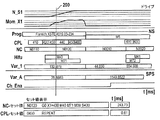
求められたタイムスタンプの基本位置に基づいて全経過(例えば回転部分の完成のためのNCプログラム)の最適化が図2に基づいて例示的に説明するように簡単な形式で可能となる。このことは本発明の枠内で行われるそのつどの(例えばタイムスタンプを用いて)求められたクロックタイプのビジュアル化を表す。表示すべき、記憶すべき、及び後からビジュアル化すべきデータは、ユーザーがプレフィールドにおいて相応のダイアローグを介して選択される。図中の一例として列N_S1はスピンドルの回転数に関わるものである。第2の列Mom_X1は軸のトルクを示している。さらに後続する列は例えば軸受け部の自動回転のためのプログラムないし下位プログラム(サブルーチン)に関している。 Based on the determined basic position of the time stamp, the optimization of the whole process (for example, the NC program for completion of the rotating part) is possible in a simple form as will be described by way of example with reference to FIG. This represents the respective clock type visualization (eg, using time stamps) that is done within the framework of the present invention. The data to be displayed, stored and later visualized is selected by the user in the pre-field via a corresponding dialog. As an example in the figure, column N_S1 relates to the number of rotations of the spindle. The second column Mom_X1 indicates the shaft torque. Further subsequent columns relate to programs or sub-programs (subroutines) for automatic rotation of the bearing section, for example.
列"PROG"は例えばメインプログラム(NCプログラム)であり、これは相応のサブルーチン、例えば工具交換を開始させるサブルーチンM6を呼出す。さらなるサブルーチンないし変数にはそれぞれさらなる略語、CPL(既述)、NC(NCセット値)、Hifu(NCとSPS(記憶プログラミング制御部)の間の迅速なデータ交換のための支援機能)、Var_1(NCの変数)、Var_2(SPSの変数)、Ch_Ena(NCとSPCの間のインターフェース信号)が付されている。カーソル200(これは例えばそれぞれの列に沿って連続的にシフト可能である)を用いることによって、個々の列において生じているクロックタイムないし制御時間の比較観察が実現可能となる。さらなるカーソルは例えば全経過に対する所定の過程の時間、例えば所定の処理シーケンスの開始時点における駆動部の加速フェーズを測定するための測定カーソルとして用いられ得る。 The column “PROG” is, for example, a main program (NC program), which calls a corresponding subroutine, for example a subroutine M6 for starting a tool change. Further subroutines or variables include additional abbreviations CPL (described above), NC (NC set value), Hifu (support function for quick data exchange between NC and SPS (memory programming control unit)), Var_1 ( NC variable), Var_2 (SPS variable), and Ch_Ena (interface signal between NC and SPC). By using the cursor 200 (which can be shifted continuously along each column, for example), a comparative observation of the clock time or control time occurring in the individual columns can be realized. The further cursor can be used, for example, as a measuring cursor for measuring the time of a predetermined process relative to the whole course, for example the acceleration phase of the drive at the start of a predetermined processing sequence.
列NCにおいてはNCセット値が表示される。ここではNCセット値N0010が比較的長く続いているのが目立っている。ここでは例えばチャネルトリガ(SPS上のCh_Ena)の予想よりも早いセットによってその実施時間が短縮されるか否かが検査されてもよい。同じようにトルク経過のセット値N0120においては最適でないように見える(図2のMom_X1参照)。ここでは次として起動及び制動フェーズにおける軸の加速トルクが詳細に検査されるべきであろう。さらなる節約の余地は、場合によってはスピンドルの回転立上がりの際に達成され得る(N_S1)。サポートファンクションM40,M71,M88を介して駆動制御される部分経過は場合によっては(より詳細な分析によって)節約の余地も提供する。またケースによっては、M71で表される"工具把持部の開放"過程がSPS上で特定の監視過程の実施の後で早期にセットされ、それに伴って工具把持部開放のための油圧バルブの駆動制御がより少ないメイン時間しか要求しない可能性もある。その他の可能性としては、サポートファンクションM71によって既にNCセット値が早期に送出されることも考えられる。 In the column NC, the NC set value is displayed. Here, it is conspicuous that the NC set value N0010 continues for a relatively long time. Here, for example, it may be checked whether the implementation time is shortened by a faster set than expected of the channel trigger (Ch_Ena on SPS). Similarly, it appears that the torque elapsed set value N0120 is not optimal (see Mom_X1 in FIG. 2). Here the shaft acceleration torque in the starting and braking phases should be examined in detail as follows. Further savings can be achieved in some cases during the spindle rotation rise (N_S1). The partial progression driven and controlled via the support functions M40, M71, M88 also provides room for saving in some cases (by more detailed analysis). In some cases, the “opening of the tool gripper” process represented by M71 is set early after the execution of a specific monitoring process on the SPS, and accordingly, the hydraulic valve is driven to open the tool gripper. There is also the possibility that less control will require less main time. Another possibility is that the NC set value is already sent out early by the support function M71.
図2の下方部分にはカーソルを介して選択されるNCセット値ないしCPLセット値並びにそのつどの実施時間が表示されている。例えば、NCセット値"G0 X1=400 M40 M71 M38 S400"は243.73msの実施時間で表され、CPLセット値"REPEAT"は0.61msの実施時間で表される。 In the lower part of FIG. 2, the NC set value or CPL set value selected via the cursor and the respective execution time are displayed. For example, the NC set value “G0 X1 = 400 M40 M71 M38 S400” is represented by an implementation time of 243.73 ms, and the CPL set value “REPEAT” is represented by an implementation time of 0.61 ms.
その他のクロックタイム分析の主要な適用ケースは、プロセスの最適化と機械の最適化であり、ここでは例えばモーターセンサ並びに外部センサの同時表示によって、処理期間中の機械の柔軟性が直接的に(あるいは必要に応じて処理プロセス全体を克服すべく)描写、記憶、表示、評価され、さらに必要に応じて最適化され得る。 Other major application cases for clock time analysis are process optimization and machine optimization, where the flexibility of the machine during processing is directly (for example, by simultaneous display of motor sensors as well as external sensors) ( Alternatively, it can be depicted, stored, displayed, evaluated, and further optimized as needed (to overcome the entire processing process as needed).
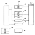
図3にはNC上で可能な内部実現が拡大して詳細に示されている。特にこの図は、特にセット値供給部150,セット値処理部166及び補間回路機能部160上で実際に現われる多くの制御レベル(時間レベル、タスク、セクション、ファンクション)の具体化のために用いられている。各NCファンクションとは以下のジョブが結合する。すなわち、
*スタートジョブ102:これは該当するNCファンクションの呼び出しの際にのみ一回だけ処理される
*モードジョブ104:これは新規に読み出された各NCセット値と共に新たに呼出される(さらなるNCコマンドによって除去されるまで)
*イグジットジョブ102:これは該当するファンクションの取り消しの際に一度だけ処理される。
FIG. 3 shows in greater detail the internal implementation possible on the NC. In particular, this figure is used to embody many control levels (time level, task, section, function) that actually appear on the set
* Start job 102: This is processed only once when the corresponding NC function is called * Mode job 104: This is newly called with each newly read NC set value (further NC command Until removed by)
* Exit job 102: This is processed only once when the corresponding function is canceled.
記録(Aufzeichnung)の介入は、選択的にNCプログラム100の中の命令(例えばOSC(1))を用いて行われるか、あるいはキーを用いた図には示されていない適切な画面を介して選択的に行われる。NCセット値及び/又はセット値に係る信号ないしセット値に関わらない信号(相応のトリガ条件も含む)の記録のためのコマンドが制御システムの部分システムから生じると同時に、NCはユーザーから設定ないし記録されたそのつどのデータ(信号)に基づいて制御システムの異なるレベルでのデータの記録のための所要のスタートジョブ(102)、モードジョブ(104)、イグジットジョブ(106)が活動化される。 The recording (Aufzeichnung) intervention is performed selectively using instructions in the NC program 100 (eg OSC (1)) or via appropriate screens not shown in the figure using keys. Done selectively. NC commands are set or recorded by the user at the same time as commands for recording NC set values and / or signals related to set values or signals not related to set values (including corresponding trigger conditions) are generated from a partial system of the control system. The required start job (102), mode job (104) and exit job (106) for recording data at different levels of the control system are activated based on the respective data (signals).
スタートジョブ(ファンクションOscOnStart及びOscOnIpoBlk)においては記録に要する準備、例えばメモリのリクエストまたはレコーディングすべきデータ、アドレス計算などが実施される。スタートジョブ102の異なるレベルないし機能は符号102a、102bで概略的に表されている。
In the start jobs (functions OscOnStart and OscOnIpoBlk), preparations required for recording, for example, memory requests or data to be recorded, address calculation, and the like are performed. Different levels or functions of the
図3では例示的に、記録に係るいくつかのモードファンクション(OscPrep,SaveBlkData,OscEndOfPrep,OscParser)がモードジョブ104の符号104a〜104dで表されている。それらはセット値供給部150、セット値処理部166及び補間回路機能部160(並びに必要に応じてその他のSPS、ドライブなどの部分システム)の異なるレベル内で、ユーザーによって選択されたデータを所属のタイムスタンプも含めてクロック同期されたクロック(図3には示されていない)を用いて記録する。このようにして例えばそのつどのNCセット値のセット値供給部レベル上でのそのつどのサブルーチン、実際のサブルーチンレベル、ツールコーディネートにおける軸位置が、そしてセット値処理部レベル上でのトラック速度及び補間回路レベル上での実際の軸速度が所属のタイムスタンプと共に記録される。
記録の終了と共にNCはイグジットジョブ(106)OscOffIpoBlkを実行し、それによって例えば一次メモリが再び開放される。
In FIG. 3, for example, several mode functions (OscPrep, SaveBlkData, OscEndOfPrep, OscParser) related to recording are represented by
At the end of the recording, the NC executes an exit job (106) OscOffIpoBlk, whereby, for example, the primary memory is released again.
NC命令OSC( )を用いて、あるいはキーを用いた図には示されていない適切な画面を介して当該記録が中断される。これに対してはNCがさらなるスタートジョブ(108)OscOffStartを処理し、モードジョブ104が除去される。
The recording is interrupted using the NC command OSC () or via an appropriate screen not shown in the figure using the keys. In response to this, the NC processes a further start job (108) OscOffStart, and the
様々なジョブ102〜108を用いることによって例えば内部のセット値メモリがリクエストされ、NCとSPSの間のアドレス、例えばチャネルインターフェース、軸インターフェース、スピンドルインターフェースが記録されるか、又はパーマネントCPL変数やSercosデータのためのトークンが求められる。 By using various jobs 102-108, for example, an internal set value memory is requested and the address between NC and SPS, eg channel interface, axis interface, spindle interface is recorded, or permanent CPL variable or Sercos data A token for is required.
図3の左下にはメモリ(159)が表されている。領域Ctr1(符号159a)は記録の構成のために用いられており、例えば信号の設定のために若しくは信号ないしデータにおけるタイムパターンに記録されている。領域BlPrepOszi(159b)はメモリに対するものであり、そこではセット値供給レベル上で求められたデータと信号が記憶される。IpoOszi(159c)のもとでは、補間回路に生じるデータと信号が記憶される。これらの2つのメモリは、NC内部で比較的長期に亘って膨大なデータ量を高いサンプリングレートで記録させるために種々のバッファメモリの形態で実現してもよい。 A memory (159) is shown in the lower left of FIG. The area Ctr1 (reference numeral 159a) is used for recording configuration, and is recorded, for example, for signal setting or in a time pattern in a signal or data. The region BlPrepOszi (159b) is for the memory, in which data and signals determined on the set value supply level are stored. Under IpoOszi (159c), data and signals generated in the interpolation circuit are stored. These two memories may be realized in the form of various buffer memories in order to record an enormous amount of data at a high sampling rate for a relatively long time inside the NC.
記録に関与するさらなるシステムの結合はシステム間のトリガ信号の転送によって行われる。部分システムに亘る時間同期された記録のための主要な前提は、部分システムの限界を超える相互に同期されるクロックである。 The further coupling of the systems involved in the recording takes place by transferring trigger signals between the systems. The main premise for time-synchronized recording across partial systems is a mutually synchronized clock that exceeds the limits of the partial system.
総じて本発明によれば、それを用いることによってクロックタイムに係るデータが記録され、記憶され、管理されてさらに異なる方式でグラフィックな表示も可能である、ツールが提供される。ここでは例えばバーグラフまたはケーキ状のダイヤグラムで表されている。本発明によれば時間検出が非常に高精度に実現される。それにより制御において全ての時間レベルのデータを検出して記録することが可能となる(IPOデータに限らない)。ここでの時間的な関係は、全ての時間レベルを克服し、特に全システムに存在する同期クロックを介して提供可能でかつグラフィックな記録によって相応のビジュアル化も可能である。これにより記録されたセット値情報とその他の異なる制御レベルで記録されたデータ及び信号が時間同期されて表示可能となる。時間同期されたグラフィックな処理シミュレーションは必要に応じて延期されてもよい(例えば前後に向けてセット値の継続が含まれるように)。 In general, according to the present invention, there is provided a tool that can be used to record, store, and manage data related to clock time and to display a graphic in a different manner. Here, for example, it is represented by a bar graph or cake diagram. According to the present invention, time detection is realized with very high accuracy. Thereby, it is possible to detect and record all time level data in the control (not limited to IPO data). The temporal relationship here overcomes all time levels and can be provided in particular via a synchronous clock present in the whole system and can also be visualized accordingly by graphic recording. As a result, the recorded set value information and data and signals recorded at other different control levels can be displayed in time synchronization. The time-synchronized graphical processing simulation may be postponed as needed (eg, to include continuation of set values back and forth).
100 NCプログラム
120〜124 クロック
150 セット値供給部
159 中間記憶メモリ
160 補間回路機能部
100
Claims (8)
各データ処理レベルに割当てられ各データ処理レベルにおける部分システムのクロックタイムを検出するためのクロックタイム検出手段(120〜124)と、各データ処理レベル毎に求められたクロックタイムの比較と時間的関係付けのための手段とが設けられていることを特徴とする自動化システム。 In an automated system with a CNC control unit, which includes at least two data processing levels, in particular a data set value supply level (150) and a data set value processing level (160),
Clock time detection means (120 to 124) assigned to each data processing level for detecting the clock time of the partial system at each data processing level, comparison of the clock times obtained for each data processing level, and temporal relationship And an automatic system.
さらに各データ処理レベル毎に求められたクロックタイムが相互に比較されて時間的に関係付けられるようにしたことを特徴とする方法。 For clock time, process and / or machine optimization of at least two data processing levels in an automated system, in particular a system comprising a data set value supplier level (150) and a data set value processing level (160) In the method, the clock time assigned to each data processing level of the partial system at each data processing level is determined,
Further, the clock time obtained for each data processing level is compared with each other and correlated in time.
Applications Claiming Priority (1)
| Application Number | Priority Date | Filing Date | Title |
|---|---|---|---|
| DE102006039244A DE102006039244A1 (en) | 2006-08-22 | 2006-08-22 | Automation system and method for cycle time, process and / or machine optimization |
Publications (2)
| Publication Number | Publication Date |
|---|---|
| JP2008052738A true JP2008052738A (en) | 2008-03-06 |
| JP2008052738A5 JP2008052738A5 (en) | 2010-07-01 |
Family
ID=38686745
Family Applications (1)
| Application Number | Title | Priority Date | Filing Date |
|---|---|---|---|
| JP2007216187A Pending JP2008052738A (en) | 2006-08-22 | 2007-08-22 | Automation system and method for clock time, process and/or machine optimization |
Country Status (4)
| Country | Link |
|---|---|
| US (1) | US9547302B2 (en) |
| EP (1) | EP1892598A3 (en) |
| JP (1) | JP2008052738A (en) |
| DE (1) | DE102006039244A1 (en) |
Families Citing this family (5)
| Publication number | Priority date | Publication date | Assignee | Title |
|---|---|---|---|---|
| EP2434357B1 (en) * | 2010-09-22 | 2020-02-12 | Siemens Aktiengesellschaft | Trace system for technology data and/or program events |
| EP2434360B1 (en) * | 2010-09-22 | 2020-01-08 | Siemens Aktiengesellschaft | Motion control system |
| CN108490876B (en) * | 2018-02-11 | 2020-10-23 | 西南交通大学 | Method for improving synchronization accuracy of numerical control machining monitoring threshold and signal |
| US11351669B2 (en) * | 2019-10-29 | 2022-06-07 | Kyndryl, Inc. | Robotic management for optimizing a number of robots |
| CN115421447A (en) * | 2022-08-20 | 2022-12-02 | 山东科技大学 | Method, system and device for evaluating and controlling time-energy efficiency of numerical control machine tool |
Citations (1)
| Publication number | Priority date | Publication date | Assignee | Title |
|---|---|---|---|---|
| JPH01131905A (en) * | 1987-10-09 | 1989-05-24 | Yokogawa Hewlett Packard Ltd | Robot joint control method |
Family Cites Families (13)
| Publication number | Priority date | Publication date | Assignee | Title |
|---|---|---|---|---|
| US4310878A (en) * | 1970-12-28 | 1982-01-12 | Hyatt Gilbert P | Digital feedback control system |
| JPS5942248A (en) | 1982-09-03 | 1984-03-08 | Mitsubishi Electric Corp | Nc machining system |
| US5483468A (en) * | 1992-10-23 | 1996-01-09 | International Business Machines Corporation | System and method for concurrent recording and displaying of system performance data |
| DE19746130B4 (en) | 1997-10-18 | 2006-01-26 | Index-Werke Gmbh & Co. Kg Hahn & Tessky | machine tool |
| US6993695B2 (en) * | 2001-06-06 | 2006-01-31 | Agilent Technologies, Inc. | Method and apparatus for testing digital devices using transition timestamps |
| US6788218B2 (en) * | 2001-07-19 | 2004-09-07 | Lancer Partnership, Ltd. | Pseudo real-time diagnostic and process monitoring system |
| US6757583B2 (en) * | 2002-06-27 | 2004-06-29 | Joe Giamona | Interpolated motion control over a serial network |
| US7580037B1 (en) * | 2003-09-05 | 2009-08-25 | Altera Corporation | Techniques for graphical analysis and manipulation of circuit timing requirements |
| US7500152B2 (en) * | 2003-12-05 | 2009-03-03 | Freescale Semiconductor, Inc. | Apparatus and method for time ordering events in a system having multiple time domains |
| DE10357824A1 (en) * | 2003-12-09 | 2005-07-14 | Kuka Roboter Gmbh | Method and device for operating cooperating different devices |
| DE102004052555A1 (en) | 2004-10-29 | 2006-05-04 | Bosch Rexroth Ag | Method for exchanging data between subscribers from different networks |
| US8090972B2 (en) * | 2007-11-26 | 2012-01-03 | Vestas Wind Systems A/S | Method and system for registering events in wind turbines of a wind power system |
| US7453910B1 (en) * | 2007-12-18 | 2008-11-18 | International Business Machines Corporation | Synchronization of independent clocks |
-
2006
- 2006-08-22 DE DE102006039244A patent/DE102006039244A1/en not_active Ceased
-
2007
- 2007-05-23 EP EP07010198A patent/EP1892598A3/en not_active Withdrawn
- 2007-08-01 US US11/832,011 patent/US9547302B2/en active Active
- 2007-08-22 JP JP2007216187A patent/JP2008052738A/en active Pending
Patent Citations (1)
| Publication number | Priority date | Publication date | Assignee | Title |
|---|---|---|---|---|
| JPH01131905A (en) * | 1987-10-09 | 1989-05-24 | Yokogawa Hewlett Packard Ltd | Robot joint control method |
Also Published As
| Publication number | Publication date |
|---|---|
| DE102006039244A1 (en) | 2008-03-06 |
| EP1892598A3 (en) | 2010-03-03 |
| US20080052554A1 (en) | 2008-02-28 |
| US9547302B2 (en) | 2017-01-17 |
| EP1892598A2 (en) | 2008-02-27 |
Similar Documents
| Publication | Publication Date | Title |
|---|---|---|
| US8588955B2 (en) | Method and apparatus for optimizing, monitoring, or analyzing a process | |
| WO2015097886A1 (en) | Machining-information management device and tool-path generation device | |
| JP2008052738A (en) | Automation system and method for clock time, process and/or machine optimization | |
| US20040210868A1 (en) | Icons and icon representation of process steps for graphic visualization of task-oriented steps | |
| JP2005011203A (en) | Numerical controller | |
| JP2009122852A (en) | Numerical controller for storing operating history during path table operation | |
| JP6638979B2 (en) | Numerical control device with machining process management function and machining process management program | |
| US6829518B2 (en) | Numerical control apparatus | |
| JP2023181497A (en) | Information processing method, program, recording medium, information processing apparatus, manufacturing system, and method for manufacturing article | |
| JP6392817B2 (en) | Simulation device | |
| JPH07191717A (en) | Automatic preparing device for control program | |
| KR20100135513A (en) | Numerical control system having graphic-based user interface | |
| JP4562591B2 (en) | Tool path drawing method and apparatus | |
| EP4006663A1 (en) | Control system, analysis method, and program | |
| JP2009080591A (en) | Numerical control device, control program, and recording medium | |
| JP4198374B2 (en) | Equipment simulation method and equipment simulation program | |
| JPH07314284A (en) | Ladder program/circuit verifying device | |
| JP2010176309A (en) | Machine tool, and method for presenting operating time of the same | |
| US11287802B2 (en) | Simulation method for simulating a real control for an industrial process, a system, or a machine, and simulation system for carrying out such a simulation method | |
| JPS58119006A (en) | Program control method of numerical control machine tool | |
| WO2022249713A1 (en) | Control system, system program, and debugging method | |
| KR20190125303A (en) | Monitor Support Devices, Monitor Support Methods, and Monitor Support Programs | |
| JP2012048471A (en) | Numerical control device and macro program execution method | |
| EP3633471B1 (en) | Program development support device, program development support system, program development support method, and program development support program | |
| JPS60118336A (en) | Punch press machine provided with numerical control device |
Legal Events
| Date | Code | Title | Description |
|---|---|---|---|
| A521 | Written amendment |
Free format text: JAPANESE INTERMEDIATE CODE: A523 Effective date: 20100517 |
|
| A621 | Written request for application examination |
Free format text: JAPANESE INTERMEDIATE CODE: A621 Effective date: 20100517 |
|
| RD04 | Notification of resignation of power of attorney |
Free format text: JAPANESE INTERMEDIATE CODE: A7424 Effective date: 20101227 |
|
| A131 | Notification of reasons for refusal |
Free format text: JAPANESE INTERMEDIATE CODE: A131 Effective date: 20120210 |
|
| A601 | Written request for extension of time |
Free format text: JAPANESE INTERMEDIATE CODE: A601 Effective date: 20120508 |
|
| A602 | Written permission of extension of time |
Free format text: JAPANESE INTERMEDIATE CODE: A602 Effective date: 20120511 |
|
| A521 | Written amendment |
Free format text: JAPANESE INTERMEDIATE CODE: A523 Effective date: 20120626 |
|
| A02 | Decision of refusal |
Free format text: JAPANESE INTERMEDIATE CODE: A02 Effective date: 20121221 |