JP2008029621A - Endoscope apparatus and capture method thereof - Google Patents
Endoscope apparatus and capture method thereof Download PDFInfo
- Publication number
- JP2008029621A JP2008029621A JP2006206830A JP2006206830A JP2008029621A JP 2008029621 A JP2008029621 A JP 2008029621A JP 2006206830 A JP2006206830 A JP 2006206830A JP 2006206830 A JP2006206830 A JP 2006206830A JP 2008029621 A JP2008029621 A JP 2008029621A
- Authority
- JP
- Japan
- Prior art keywords
- image
- image sensor
- light source
- still image
- cmos image
- Prior art date
- Legal status (The legal status is an assumption and is not a legal conclusion. Google has not performed a legal analysis and makes no representation as to the accuracy of the status listed.)
- Granted
Links
Images


Classifications
-
- A—HUMAN NECESSITIES
- A61—MEDICAL OR VETERINARY SCIENCE; HYGIENE
- A61B—DIAGNOSIS; SURGERY; IDENTIFICATION
- A61B1/00—Instruments for performing medical examinations of the interior of cavities or tubes of the body by visual or photographical inspection, e.g. endoscopes; Illuminating arrangements therefor
- A61B1/04—Instruments for performing medical examinations of the interior of cavities or tubes of the body by visual or photographical inspection, e.g. endoscopes; Illuminating arrangements therefor combined with photographic or television appliances
- A61B1/045—Control thereof
-
- A—HUMAN NECESSITIES
- A61—MEDICAL OR VETERINARY SCIENCE; HYGIENE
- A61B—DIAGNOSIS; SURGERY; IDENTIFICATION
- A61B1/00—Instruments for performing medical examinations of the interior of cavities or tubes of the body by visual or photographical inspection, e.g. endoscopes; Illuminating arrangements therefor
- A61B1/04—Instruments for performing medical examinations of the interior of cavities or tubes of the body by visual or photographical inspection, e.g. endoscopes; Illuminating arrangements therefor combined with photographic or television appliances
- A61B1/042—Instruments for performing medical examinations of the interior of cavities or tubes of the body by visual or photographical inspection, e.g. endoscopes; Illuminating arrangements therefor combined with photographic or television appliances characterised by a proximal camera, e.g. a CCD camera
-
- A—HUMAN NECESSITIES
- A61—MEDICAL OR VETERINARY SCIENCE; HYGIENE
- A61B—DIAGNOSIS; SURGERY; IDENTIFICATION
- A61B1/00—Instruments for performing medical examinations of the interior of cavities or tubes of the body by visual or photographical inspection, e.g. endoscopes; Illuminating arrangements therefor
- A61B1/04—Instruments for performing medical examinations of the interior of cavities or tubes of the body by visual or photographical inspection, e.g. endoscopes; Illuminating arrangements therefor combined with photographic or television appliances
- A61B1/05—Instruments for performing medical examinations of the interior of cavities or tubes of the body by visual or photographical inspection, e.g. endoscopes; Illuminating arrangements therefor combined with photographic or television appliances characterised by the image sensor, e.g. camera, being in the distal end portion
-
- A—HUMAN NECESSITIES
- A61—MEDICAL OR VETERINARY SCIENCE; HYGIENE
- A61B—DIAGNOSIS; SURGERY; IDENTIFICATION
- A61B1/00—Instruments for performing medical examinations of the interior of cavities or tubes of the body by visual or photographical inspection, e.g. endoscopes; Illuminating arrangements therefor
- A61B1/06—Instruments for performing medical examinations of the interior of cavities or tubes of the body by visual or photographical inspection, e.g. endoscopes; Illuminating arrangements therefor with illuminating arrangements
- A61B1/0661—Endoscope light sources
- A61B1/0676—Endoscope light sources at distal tip of an endoscope
-
- A—HUMAN NECESSITIES
- A61—MEDICAL OR VETERINARY SCIENCE; HYGIENE
- A61B—DIAGNOSIS; SURGERY; IDENTIFICATION
- A61B1/00—Instruments for performing medical examinations of the interior of cavities or tubes of the body by visual or photographical inspection, e.g. endoscopes; Illuminating arrangements therefor
- A61B1/06—Instruments for performing medical examinations of the interior of cavities or tubes of the body by visual or photographical inspection, e.g. endoscopes; Illuminating arrangements therefor with illuminating arrangements
- A61B1/0661—Endoscope light sources
- A61B1/0684—Endoscope light sources using light emitting diodes [LED]
Landscapes
- Health & Medical Sciences (AREA)
- Life Sciences & Earth Sciences (AREA)
- Surgery (AREA)
- Physics & Mathematics (AREA)
- Engineering & Computer Science (AREA)
- Optics & Photonics (AREA)
- Biomedical Technology (AREA)
- Molecular Biology (AREA)
- Pathology (AREA)
- Nuclear Medicine, Radiotherapy & Molecular Imaging (AREA)
- Biophysics (AREA)
- Heart & Thoracic Surgery (AREA)
- Medical Informatics (AREA)
- Radiology & Medical Imaging (AREA)
- Animal Behavior & Ethology (AREA)
- General Health & Medical Sciences (AREA)
- Public Health (AREA)
- Veterinary Medicine (AREA)
- Microelectronics & Electronic Packaging (AREA)
- Endoscopes (AREA)
- Studio Devices (AREA)
- Transforming Light Signals Into Electric Signals (AREA)
Abstract
Description
本発明は、内視鏡装置に挿入部先端に設けられる撮像素子の信号処理に関する。 The present invention relates to signal processing of an image sensor provided at the distal end of an insertion portion in an endoscope apparatus.
一般に、内視鏡装置の挿入部先端には、体腔内を照明する光源(ライトガイド等)と、観察像を取り込むための対物レンズが取り付けられている。対物レンズにより結像された観察像は、固体撮像素子(例えば、CCDイメージセンサ又はCMOSイメージセンサ)により光電変換され、画像信号として、カメラコントロールユニット(CCU)に送出され、ホワイトバランス調整など種々の画像処理が施された後、表示部に表示されている。 In general, a light source (light guide or the like) for illuminating the inside of a body cavity and an objective lens for capturing an observation image are attached to the distal end of the insertion portion of the endoscope apparatus. An observation image formed by the objective lens is photoelectrically converted by a solid-state imaging device (for example, a CCD image sensor or a CMOS image sensor), sent to a camera control unit (CCU) as an image signal, and variously adjusted such as white balance adjustment. After the image processing is performed, the image is displayed on the display unit.
観察者は、操作部を操作して体腔内の形状に沿うように挿入部先端を屈曲させつつ挿入して、動画像を観察し、且つ操作部に設けられたシャッタスイッチを操作して、必要と思われる観察箇所を静止画像として撮影している。
前述した固体撮像素子による静止画像を撮像する場合、被写体の明るさにもよるが、動きの速い被写体の静止画像には像ブレ等が発生しやすい傾向がある。例えば、非特許文献1に記載されているように、CCDイメージセンサは、全画素に対して、垂直CCDに蓄積されている電荷を同時に読み出すことができる。この動作を電子シャッタと組み合わせることにより、比較的に動きの速い被写体に対しても追従して、ブレのない静止画像を得ることができる。しかし、CCDイメージセンサは、CMOSイメージセンサのようにLSI製造プロセスに近い製造工程では作成できないため、1チップ化(システム・オン・チップ)を実現する際に製造コストがかかり高価である。
When a still image is captured by the above-described solid-state image sensor, image blurring or the like tends to occur in a still image of a fast-moving subject, depending on the brightness of the subject. For example, as described in Non-Patent
一方、CMOSイメージセンサは、XYアドレス方式であり、各画素に設けられたスイッチが順次オンされて蓄積された電荷が読み出されている。従って、CMOSイメージセンサは、画素単位で蓄積された電荷が増幅されて出力されているため、CCDイメージセンサに比べて信号伝達回路上でノイズの影響を受けにくく且つ、XYアドレスを指定して読み出すため、読み出しを行う画素領域が制御できるという利点がある。つまり、観察画像全体から見て必要領域のみを指定(トリミング又はズーミング)することができる。その反面、1画像(又はフレーム)において読み出される最初の画素から最後の画素までの読み出し時間までのタイミングにずれが発生する。即ち、CMOSイメージセンサは、画素各々が電荷を読み出された直後から再度電荷の蓄積を開始するため、電荷蓄積の同時性がないという問題を有している。 On the other hand, the CMOS image sensor is based on the XY address method, and the switches provided in each pixel are sequentially turned on to read the accumulated charges. Therefore, in the CMOS image sensor, since the charges accumulated in pixel units are amplified and output, compared to the CCD image sensor, the CMOS image sensor is less susceptible to noise on the signal transmission circuit, and is read by specifying the XY address. Therefore, there is an advantage that the pixel region for reading can be controlled. That is, it is possible to designate (trimming or zooming) only a necessary region as seen from the entire observation image. On the other hand, a deviation occurs in the timing from the first pixel to the last pixel read in one image (or frame). That is, the CMOS image sensor has a problem that there is no simultaneous charge accumulation because charge accumulation is started again immediately after each pixel has read out the charge.
従って、動きの速い被写体を撮像する場合、最初の画素の電荷を読み出したときの被写体構図と、最後の画素の電荷を読み出したときの被写体構図とでは、被写体が変化しており異なっていることとなる。これらの異なる被写体構図における電荷により、1枚の静止画像を構築した場合には、被写体像に歪みが発生する。このような現象については、例えば非特許文献1で説明されている。
Therefore, when imaging a fast-moving subject, the subject changes between the subject composition when the charge of the first pixel is read out and the subject composition when the charge of the last pixel is read out and are different. It becomes. When one still image is constructed by the charges in these different subject compositions, the subject image is distorted. Such a phenomenon is described in
この被写体像に歪みを防止する技術として、特許文献1には、メカニカルシャッタ機構を搭載して、静止画像の撮像前にシャッタを閉じた状態で蓄積された電荷をリセットする画像処理装置が提案されている。このようなシャッタ機構を内視鏡装置の挿入部先端に設けることは難しく、また滅菌処理を実施するに際して衛生面から見てもあまり好ましくはない。
As a technique for preventing distortion in the subject image,
そこで本発明は、CMOSイメージセンサによる撮像時に電荷蓄積の同時性を有し、動きの速い被写体であっても画像の歪み及び像ずれのない観察像を撮像することができる内視鏡装置及びその撮像方法を提供することを目的とする。 Therefore, the present invention provides an endoscope apparatus capable of capturing an observation image without distortion and image displacement even in a fast-moving subject, having charge accumulation at the time of imaging by a CMOS image sensor. An object is to provide an imaging method.
本発明は上記目的を達成するために、外光が届かない体腔内で光源により照明された被写体を先端に設けたCMOSイメージセンサで動画像又は静止画像からなる観察像を撮像する挿入部及び、該挿入部に連結して静止画の撮像指示を行うためのスイッチが設けられた内視鏡本体と、前記スイッチの操作により前記光源を消灯し、前記CMOSイメージセンサの全画素内に蓄積されている電荷をリセットした後、該リセットの状態から前記光源を点灯させて、前記CMOSイメージセンサによる静止画像の撮像を行い、撮像終了後に前記光源による照明を消灯させて各画素から電荷を読み出す静止画像撮像制御を行う制御部を有するカメラコントロールユニットと、撮像された前記動画像又は前記静止画像からなる観察像及び該観察像に関する情報を表示するモニタと、を備える内視鏡装置を提供する。 In order to achieve the above object, the present invention provides an insertion unit for capturing an observation image consisting of a moving image or a still image with a CMOS image sensor having a subject illuminated by a light source in a body cavity where external light does not reach, at the tip, and An endoscope main body provided with a switch connected to the insertion portion to instruct to take a still image, and the light source is turned off by the operation of the switch, and is stored in all the pixels of the CMOS image sensor. After resetting the charged electric charge, the light source is turned on from the reset state, a still image is taken by the CMOS image sensor, and the illumination by the light source is turned off after the imaging is finished to read the charge from each pixel. A camera control unit having a control unit that performs imaging control, an observation image composed of the captured moving image or the still image, and the observation image To provide an endoscope apparatus comprising a monitor for displaying the information.
さらに、本発明は、光源で照明された体腔内の被写体をCMOSイメージセンサにより撮像し、動画像又は静止画像からなる観察画像として観察する内視鏡装置の撮像方法であって、前記体腔内で静止画像を撮像する際に、前記光源を消灯させて、前記CMOSイメージセンサの各画素内に蓄積されている電荷量をリセットし、該リセットの状態から光源を点灯させて、前記CMOSイメージセンサによる静止画像の撮像を行い、各画素から電荷を読み出す間、前記光源を再度消灯させることにより、前記CMOSイメージセンサの画素に対する蓄積の同時性を制御することを特徴とする内視鏡装置の撮像方法を提供する。 Furthermore, the present invention is an imaging method of an endoscope apparatus in which a subject in a body cavity illuminated by a light source is imaged by a CMOS image sensor and observed as an observation image consisting of a moving image or a still image, When capturing a still image, the light source is turned off to reset the amount of charge accumulated in each pixel of the CMOS image sensor, the light source is turned on from the reset state, and the CMOS image sensor An imaging method for an endoscopic device, which controls the simultaneity of accumulation in the pixels of the CMOS image sensor by turning off the light source again while taking a still image and reading out charges from each pixel. I will provide a.
本発明によれば、CMOSイメージセンサによる撮像時に電荷蓄積の同時性を有し、動きの速い被写体であっても画像の歪み及び像ずれのない観察像を撮像することができる内視鏡装置及びその撮像方法を提供することができる。 According to the present invention, there is provided an endoscope apparatus capable of capturing an observation image without distortion and image displacement even with a fast-moving subject, having charge accumulation at the time of imaging by a CMOS image sensor. The imaging method can be provided.
以下、図面を参照して本発明の実施形態について詳細に説明する。
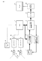
図1には、本発明に係る撮像システムの概略的な構成例を示す。
この撮像システムは、被写体を撮像し光電変換により画像信号を生成するCMOSイメージセンサ1と、CMOSイメージセンサ1を駆動するCMOSセンサ駆動制御回路2と、生成された画像信号に対して、ノイズ除去及びゲイン調整を施しデジタル信号化を行うためのノイズ除去回路/AGC/AD回路3と、デジタル画像信号に対して画像合成やホワイトバランス処理などの種々の画像処理を行うデジタル信号処理部(DSP)4と、CMOSイメージセンサ1の撮像時に撮像範囲を照明する光源5(LED5a,5b)と、LED5a,5bの発光量を制御し駆動するLEDドライバ6(6a,6b)と、装置全体の制御及び演算処理を行う中央処理部(CPU:制御部)7と、CMOSイメージセンサ1による静止画像を撮像するためのシャッタ指示(トリガ動作)を行うフリーズSW8と、DSP4から出力された画像処理された画像データをフレーム単位又は画像1枚単位で格納するメモリ部9と、画像データを表示させるため処理(例えば、アナログ化処理等)を施し、モニタ11に出力するDA回路/ドライバ10と、動画像又は静止画像からなる観察像及び該観察像に関する情報(観察位置やパラメータ等)を表示する液晶ディスプレイ等の表示用モニタ11とで構成される。
Hereinafter, embodiments of the present invention will be described in detail with reference to the drawings.
FIG. 1 shows a schematic configuration example of an imaging system according to the present invention.
This imaging system includes a
図2には、第1の実施形態として、前述した撮像システムを搭載する内視鏡装置の構成例を示す。本実施形態の構成部位において、図1に示した構成部位と同等の部位には同じ参照符号を付して、その説明を省略する。 FIG. 2 shows a configuration example of an endoscope apparatus equipped with the above-described imaging system as the first embodiment. In the constituent parts of the present embodiment, the same parts as those shown in FIG.
この内視鏡装置は、殆ど外光が届かない体腔内(闇空間)に挿入される挿入部21と、挿入部21に連結し静止画撮像の指示を行うためのフリーズSW8が設けられた操作部22と、撮像素子及び光源を駆動制御し撮像された画像信号に種々の処理を施すカメラコントロールユニット(CCU)24と、撮像された観察像を表示するモニタ11と、で構成される。挿入部21と操作部22により内視鏡装置本体が構成され、複数の信号線からなるケーブル23によりCCU24に接続されて撮像された画像信号及びフリーズ信号を含む各制御信号の伝搬が行われる。尚、内視鏡装置本体は、挿入部21が可撓性を有し、操作部22に設けられた操作部位により可撓制御が行われる構成であってもよい。
This endoscope apparatus is provided with an
挿入部21の先端部分には、CMOSイメージセンサ1とLED5a,5bと図示しない鉗子孔(鉗子通路)が設けられている。ここでの鉗子孔についての説明は省略する。CMOSイメージセンサ1は、ケーブル23を介してCMOSセンサ駆動・制御回路2に接続され、LED5a,5bは、ケーブル23を介してLEDドライバ6a,6bに接続されている。
A
CCU24は、撮像に関するもののみを図示しており、少なくとも前述したCMOSセンサ駆動制御回路2と、AFE(ノイズ除去回路/AGC/AD回路)3と、デジタル信号処理部DSP4と、LEDドライバ6と、CPU7と、メモリ部9と、DA回路10a,ドライバ10b(DA回路/ドライバ10)とを備えている。その他、内視鏡装置の駆動に必要な通常の構成部位は備えているものとして、その説明は省略する。
The CCU 24 shows only the one related to imaging. At least the CMOS sensor
尚、この内視鏡装置の構成例では、LED5a,5bを挿入部21の先端部分に設けているが、他にも、操作部22内又はCCU24内に設けて、ライトガイドにより導光してもよい。また、LEDに換わって、レーザダイオードを用いてもよい。CCU24内に光源を設ける構成であれば、点灯及び消灯の応答が速いランプを用いることもできる。さらに、本実施形態では、1つのCMOSイメージセンサを用いた構成例であったが、2つ以上のCMOSイメージセンサを用いて、立体画像を撮像する撮像システムにも適用できる。 本実施形態は、体腔内で静止画像を撮像するにあたって、まず、LED5a,5bを消灯させて、CMOSイメージセンサ2の各画素内に、これまでに蓄積されている電荷を高速に読み出して(掃き出して)、電荷量を“0”にリセットする。尚、このリセットは、電荷量は必ずしも全ての画素が0になることに限定されるものではなく、できる限り“0”に近くなるように掃き出されることが好ましく、且つ静止画像撮像前に全ての画素が均一な電荷量であることが好適する。または、グローバルセット機能を備えるCMOSイメージセンサであれば、全画素の電荷量をリセットする。ここでは、LED5a,5bを消灯させた場合、体腔内にあるCMOSイメージセンサ2に殆ど外光が届かず、各画素には電荷が蓄積されないものとする。
In this configuration example of the endoscope apparatus, the
これらの手法により、各画素に蓄積された電荷をリセットすると、CMOSイメージセンサ2の全画素には電荷が蓄積されていない状態となる。このリセット状態からLED5a,5bを点灯させてCMOSイメージセンサによる静止画像の撮像を行う。従って、CMOSイメージセンサ2の画素に対する蓄積の同時性を実現する。
When the charge accumulated in each pixel is reset by these methods, no charge is accumulated in all the pixels of the
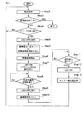
図3に示すタイミングチャート及び図4に示すフローチャートを参照して、この構成における撮像動作について詳細に説明する。
まず、体腔内に挿入部21が挿入され、CMOSイメージセンサ2に撮像された動画像の観察像がモニタ11に表示される(Step1)。その後、体腔内の観察終了の操作があったか否かを判定する(Step2)。ここで観察終了であれば、シーケンスを終了させる。一方、観察終了でなく(NO)、静止画像の撮像を行うためのフリーズSW8のオン操作があったか否かを判定する(Step3)。この判定で、フリーズSW8のオン操作がなければ(NO)、ステップ1に戻り、動画表示を継続する。一方、フリーズSW8のオン操作が行われたならば(YES)、図3におけるフリーズ信号が発生すると共に、LED5a,5bが消灯する(時間t1)。その後、期間taの間に全画素における蓄積電荷S1,S2が高速で掃き出され、リセットされる(Step5)。又は、グローバルセット機能により全画素に蓄積された電荷が一括的にリセットされる。
With reference to the timing chart shown in FIG. 3 and the flowchart shown in FIG. 4, the imaging operation in this configuration will be described in detail.
First, the
次に、電荷リセット完了後(時間t2)に、LED5a,5bが点灯され(Step6)、CMOSイメージセンサ2の全画素に対して電荷の蓄積が一斉に開始される(Step7)。この時の点灯は、フラッシュ点灯(点滅を含む)でもよいし、通常の点灯であってもよい。また、静止画像の撮像時の照明光S5は、撮像時間の高速化を図るために、図3に示すように、動画像を表示する際の照明光量S4,S6よりも多くするように設計されている。
Next, after completion of the charge reset (time t2), the
そして、想定した電荷量S3が全画素に蓄積される予め定めた設定時間(チャージアップ期間tb)が経過したか否かを判定する(Step8)。この判定で、設定時間が経過した(時間t3)ならば(YES)、LED5a,5bを消灯させると共に(Step9)、CMOSイメージセンサ2の画素から蓄積された電荷の読み出しが開始される(Step10)。尚、電荷の読み出しは、全画素からの電荷読み出しと、例えばトリミングやズーミング等による画素全体から見て一部の領域の画素からの読み出しとがある。
Then, it is determined whether or not a predetermined set time (charge up period tb) during which the assumed charge amount S3 is accumulated in all the pixels has elapsed (Step 8). If it is determined that the set time has elapsed (time t3) (YES), the
ここで、照明の消灯を伴う画素からの電荷の読み出しについて説明する。CMOSイメージセンサ2は、課題の項でも説明したように、構成上、全画素に対して同時読み出しを行うことができず、XYアドレス方式による順次読み出しとなる。従って、電荷の読み出し順が遅い画素ほど、受光する時間が長くなり電荷が蓄積されてしまう。そこで本実施形態では、各画素から電荷を順次読み出す際に、LED5a,5bを消灯させておくことにより、読み出し前の画素に対して、さらに電荷を蓄積させないようにしている。この操作により、通常の速度で電荷を読み出しても、全画素に対して同じ受光時間となるため、歪みが生じていない観察像を作成することができる。
Here, reading of electric charges from a pixel accompanying turning off of illumination will be described. As described in the section of the problem, the
次に、各画素から電荷の読み出し(期間tc)が終了したか否かを判定する(Step11)。この判定で読み出しが終了したならば、LED5a,5bを点灯し(Step12)、動画像の取り込みを開始する。この時、撮像確認を行わせるために、モニタ11に動画像を表示させる前に撮像した静止画像を表示させる(Step13)。この静止画像をモニタ11に確認に必要な時間が経過すると、自動的に動画像に切り換えられる。勿論、別途、スイッチを操作して手動により静止画像から動画像に切り換えることも可能である。
Next, it is determined whether or not the readout of charges from each pixel (period tc) has ended (Step 11). If reading is completed in this determination, the
以上説明したように、本実施形態の第1の実施形態に係る撮像システムは、体腔内等の闇空間内に内視鏡の挿入部21が挿入され、静止画像の撮像にあたり、消灯下でCMOSイメージセンサ2の全画素に蓄積されている電荷がリセットされる。このリセットにより、各画素に異なる電荷量で蓄積されていたそれぞれの電荷が無くなり、0又は0に近い略同一値の電荷となる。さらに、この時点から光源を点灯して被写体を照明し、各画素に対して所望する光量が得られた後に消灯し、消灯下で各画素に蓄積された電荷の読み出しを行う。この消灯下の電荷読み出しは、電子スチルカメラのおける露光後にシャッタを閉じた状態で撮像素子から電荷を読み出すことと全く同じ状態を作り出している。このため、画素から電荷読み出している最中に、読み出し前の画素に対して、更なる光量が与えられることがなく、静止画像の像ブレや歪みの発生を防止させることができる。
As described above, in the imaging system according to the first embodiment of the present embodiment, the
また本実施形態の撮像システムは、体腔内以外であっても、光源の消灯時にCMOSイメージセンサに光量を与えない被写体環境であれば適用することができる。例えば、敷設された管等の内部を移動する又は動く被写体を撮像する撮像システムが考えられる。 In addition, the imaging system of the present embodiment can be applied to a subject environment that does not give light to the CMOS image sensor when the light source is turned off, even outside the body cavity. For example, an imaging system that images a moving or moving subject inside a laid pipe or the like can be considered.
次に図5に示すタイミングチャートを参照して、第2の実施形態について説明する。
本実施形態は前述した第1の実施形態に対して、光源、即ちLED5a,5bの単位時間あたりの発光光量を増大させて、CMOSイメージセンサ2の各画素における電荷の蓄積時間を短時間化させる例である。本実施形態の構成は、光源(LED5a,5b)の発光量以外は前述した第1の実施形態の構成と同等であり、同じ参照符号を用いて構成の説明を省略する。
Next, a second embodiment will be described with reference to a timing chart shown in FIG.
Compared with the first embodiment described above, the present embodiment increases the amount of light emitted per unit time of the light source, that is, the
本実施形態は、図5に示すように、フリーズSW8のオン操作によるフリーズ信号が発生すると共に、LED5a,5bが消灯する(時間t1)。その後、期間taの間に全画素における蓄積電荷S1,S2がリセットされる。電荷リセット完了後(時間t2)に、LED5a,5bが点灯され、第1の実施形態に比べて大光量の照明光が照射される。大光量で点灯することにより、露光時間が短時間化される。これにより、さらに、像ぶれや歪みの少ない静止画像を得ることもできる。この時の点灯は、フラッシュ点灯(点滅を含む)でもよいし、通常の点灯であってもよい。この照明下において、短時間で各画素の電荷が所望する電荷量までチャージアップされる。この例では、図5に示すように、チャージアップ期間td後に、LED5a,5bを消灯させると共に、CMOSイメージセンサ2の画素から蓄積された電荷の読み出しが開始される。電荷の読み出し完了後の任意期間teの後に、LED5a,5bが点灯され(時間t6)、動画像の取り込みが開始される。この時、第1の実施形態と同様に、確認のために、モニタ11に撮像した静止画像を表示させて、その後、動画像に切り換える。
In the present embodiment, as shown in FIG. 5, a freeze signal is generated when the
このように大光量の照明光を照射させるために、LEDドライバによる発光制御の他に、種々の方法がある。例えば、発光光量の大きいLEDを選択しまたはLEDの数量を増やして発光制御する。または発光光量の大きいLEDを選択し、2つのLEDのうち動画像の撮像時には1つのLEDを点灯させ、静止画像の撮像時には2つのLEDを点灯させる等が考えられる。 In order to irradiate a large amount of illumination light in this way, there are various methods in addition to the light emission control by the LED driver. For example, light emission control is performed by selecting an LED having a large light emission amount or increasing the number of LEDs. Alternatively, it is conceivable to select an LED with a large amount of emitted light and turn on one of the two LEDs when capturing a moving image, and turn on two LEDs when capturing a still image.
また、CMOSイメージセンサにおける電荷の読み出しは、CCDに比べて読み出し速度の高速化が実現しやすい。これは、XYアドレス方式を構成するための読み出し用配線(行選択線及び列信号線)を複線化することにより、略同時に複数の画素から読み出しを行い、見かけ上の読み出し速度を上げることにより、直後のフィールドで静止画像をモニタ表示させることもできる。 In addition, the reading of charges in the CMOS image sensor can be easily realized at a higher reading speed than the CCD. This is because the readout wiring (row selection line and column signal line) for configuring the XY address system is double-lined, so that readout is performed from a plurality of pixels substantially simultaneously, and the apparent readout speed is increased. Still images can be displayed on the monitor in the field immediately after.
本発明は、以下の発明を含んでいる。
(1)外光が届かない闇空間で照明された被写体を撮像し光電変換により画像信号を生成するCMOSイメージセンサと、
前記CMOSイメージセンサを駆動するCMOSセンサ駆動制御回路と、
生成された画像信号に対して、ノイズ除去含む信号調整及びデジタル化処理を行う信号調整回路と、
デジタル画像信号に対して画像処理を施すデジタル信号処理部と、
画像処理された画像信号をフレーム単位又は画像1枚単位で格納するメモリ部と、
CMOSイメージセンサの撮像時に撮像範囲を照明する光源と、
前記光源の発光量を制御し駆動する光源駆動部と、
装置全体の制御及び演算処理を行う中央処理部と、
前記CMOSイメージセンサによる静止画像を撮像するためのシャッタ指示を行うフリーズSWと、
デジタル信号処理部DSP4から出力された画像データを記録するメモリ部と、
画像データを表示させるため処理を施す表示駆動部と、
表示駆動部から出力された画像信号を表示するモニタと、で構成され、
前記フリーズSWにより静止画像を撮像するに先だって、前記光源による照明を消灯し、前記CMOSイメージセンサの各画素内に蓄積されている電荷をリセットし、該リセット状態から前記光源を点灯させて、該CMOSイメージセンサによる静止画像の撮像を行い、撮像終了後に各画素から電荷を読み出す間、前記光源による照明を消灯させて、読み出し前の画素に対して、さらに電荷を蓄積させないように、前記CMOSイメージセンサの画素に対する蓄積の同時性を制御することを特徴とする撮像システム。
The present invention includes the following inventions.
(1) a CMOS image sensor that images a subject illuminated in a dark space where external light does not reach and generates an image signal by photoelectric conversion;
A CMOS sensor drive control circuit for driving the CMOS image sensor;
A signal adjustment circuit that performs signal adjustment including noise removal and digitization processing on the generated image signal;
A digital signal processing unit that performs image processing on the digital image signal;
A memory unit for storing image processed image signals in units of frames or in units of one image;
A light source that illuminates the imaging range when imaging with a CMOS image sensor;
A light source driving unit that controls and drives the light emission amount of the light source;
A central processing unit for controlling and calculating the entire apparatus;
A freeze SW for giving a shutter instruction for capturing a still image by the CMOS image sensor;
A memory unit for recording image data output from the digital signal processing unit DSP4;
A display driver that performs processing to display image data;
And a monitor that displays the image signal output from the display drive unit,
Prior to capturing a still image with the freeze SW, the illumination by the light source is turned off, the charge accumulated in each pixel of the CMOS image sensor is reset, the light source is turned on from the reset state, and the light source is turned on. The CMOS image sensor captures a still image by a CMOS image sensor and turns off the illumination by the light source while reading out charges from each pixel after the imaging is completed, so that charges are not further accumulated in the pixels before reading. An imaging system characterized by controlling the simultaneity of accumulation with respect to pixels of a sensor.
1…CMOSイメージセンサ、2…CMOSセンサ駆動制御回路、3…ノイズ除去回路/AGC/AD回路(AFE)、4…デジタル信号処理部(DSP)、5,5a,5b…LED(光源)、6,6a,6b…LEDドライバ、7…中央処理部(CPU)、8…フリーズSW、9…メモリ部、10…DA回路/ドライバ、10a…DA回路、10b…ドライバ、11…モニタ、21…挿入部、22…操作部、23…ケーブル、24…カメラコントロールユニット(CCU)。
DESCRIPTION OF
Claims (3)
前記スイッチの操作により前記光源を消灯し、前記CMOSイメージセンサの全画素内に蓄積されている電荷をリセットした後、該リセットの状態から前記光源を点灯させて、前記CMOSイメージセンサによる静止画像の撮像を行い、撮像終了後に前記光源による照明を消灯させて各画素から電荷を読み出す静止画像撮像制御を行う制御部を有するカメラコントロールユニットと、
撮像された前記動画像又は前記静止画像からなる観察像及び該観察像に関する情報を表示するモニタと、
を具備することを特徴とする内視鏡装置。 A CMOS image sensor having a subject illuminated by a light source in a body cavity where external light does not reach is provided at the tip, and an imaging unit that captures an observation image composed of a moving image or a still image, and a still image that is connected to the insertion unit An endoscope body provided with a switch for instructing;
The light source is turned off by the operation of the switch, the charge accumulated in all the pixels of the CMOS image sensor is reset, the light source is turned on from the reset state, and a still image by the CMOS image sensor is A camera control unit having a control unit that performs imaging and controls still image imaging to read out charges from each pixel by turning off illumination by the light source after completion of imaging;
A monitor that displays an observation image composed of the captured moving image or the still image and information related to the observation image;
An endoscope apparatus comprising:
前記光源は、前記挿入部の先端又は前記操作部内の何れかに設けられ、発光ダイオード(LED)又はレーザダイオードの何れかにより構成されることを特徴とする請求項1に記載の内視鏡装置。 In the endoscope apparatus,
The endoscope apparatus according to claim 1, wherein the light source is provided at either the distal end of the insertion portion or the operation portion, and is configured by either a light emitting diode (LED) or a laser diode. .
前記体腔内で静止画像を撮像する際に、前記光源を消灯させて、前記CMOSイメージセンサの各画素内に蓄積されている電荷量をリセットし、該リセットの状態から光源を点灯させて、前記CMOSイメージセンサによる静止画像の撮像を行い、各画素から電荷を読み出す間、前記光源を再度消灯させることにより、前記CMOSイメージセンサの画素に対する蓄積の同時性を制御することを特徴とする内視鏡装置の撮像方法。 An imaging method of an endoscope apparatus that images a subject in a body cavity illuminated by a light source with a CMOS image sensor and observes it as an observation image consisting of a moving image or a still image,
When capturing a still image in the body cavity, turn off the light source, reset the amount of charge accumulated in each pixel of the CMOS image sensor, turn on the light source from the reset state, An endoscope which controls the simultaneity of accumulation in the pixels of the CMOS image sensor by taking a still image by a CMOS image sensor and turning off the light source again while reading out electric charges from each pixel. Device imaging method.
Priority Applications (5)
| Application Number | Priority Date | Filing Date | Title |
|---|---|---|---|
| JP2006206830A JP5226195B2 (en) | 2006-07-28 | 2006-07-28 | Endoscope apparatus and method for operating endoscope apparatus |
| CN 200710128189 CN101112303B (en) | 2006-07-28 | 2007-07-10 | Endoscopic apparatus and image pickup method for the same |
| CN 200720156608 CN201058015Y (en) | 2006-07-28 | 2007-07-10 | Endoscope device |
| DE200710034351 DE102007034351A1 (en) | 2006-07-28 | 2007-07-24 | Endoscopy device and image recording method therefor |
| US11/881,719 US8932206B2 (en) | 2006-07-28 | 2007-07-27 | Endoscopic apparatus and image pickup method for the same |
Applications Claiming Priority (1)
| Application Number | Priority Date | Filing Date | Title |
|---|---|---|---|
| JP2006206830A JP5226195B2 (en) | 2006-07-28 | 2006-07-28 | Endoscope apparatus and method for operating endoscope apparatus |
Publications (2)
| Publication Number | Publication Date |
|---|---|
| JP2008029621A true JP2008029621A (en) | 2008-02-14 |
| JP5226195B2 JP5226195B2 (en) | 2013-07-03 |
Family
ID=38922323
Family Applications (1)
| Application Number | Title | Priority Date | Filing Date |
|---|---|---|---|
| JP2006206830A Active JP5226195B2 (en) | 2006-07-28 | 2006-07-28 | Endoscope apparatus and method for operating endoscope apparatus |
Country Status (4)
| Country | Link |
|---|---|
| US (1) | US8932206B2 (en) |
| JP (1) | JP5226195B2 (en) |
| CN (2) | CN101112303B (en) |
| DE (1) | DE102007034351A1 (en) |
Cited By (11)
| Publication number | Priority date | Publication date | Assignee | Title |
|---|---|---|---|---|
| JP2010068992A (en) * | 2008-09-18 | 2010-04-02 | Fujifilm Corp | Electronic endoscope system |
| WO2011053074A2 (en) * | 2009-11-02 | 2011-05-05 | 전북대학교산학협력단 | Functional diagnostic imaging apparatus by endoscopic optical coherence tomography |
| JP2011092683A (en) * | 2009-09-29 | 2011-05-12 | Fujifilm Corp | Electronic endoscope |
| JP2011135248A (en) * | 2009-12-24 | 2011-07-07 | Nec Corp | Mobile terminal device and display control method thereof |
| JP2011206336A (en) * | 2010-03-30 | 2011-10-20 | Fujifilm Corp | Endoscopic system |
| EP2407088A2 (en) | 2010-07-15 | 2012-01-18 | Fujifilm Corporation | Endoscope beam source apparatus and endoscope system |
| WO2013175908A1 (en) | 2012-05-25 | 2013-11-28 | オリンパスメディカルシステムズ株式会社 | Imaging system |
| JP2014183908A (en) * | 2013-03-22 | 2014-10-02 | Olympus Medical Systems Corp | Imaging system |
| JP2014183909A (en) * | 2013-03-22 | 2014-10-02 | Olympus Medical Systems Corp | Imaging system |
| WO2017082091A1 (en) * | 2015-11-13 | 2017-05-18 | ソニー株式会社 | Surgery system, control method for surgery, and program |
| US11337595B2 (en) | 2016-10-24 | 2022-05-24 | Olympus Corporation | Endoscope apparatus for determining situation of occurrence of rolling distortion |
Families Citing this family (17)
| Publication number | Priority date | Publication date | Assignee | Title |
|---|---|---|---|---|
| JP2009189654A (en) * | 2008-02-15 | 2009-08-27 | Olympus Medical Systems Corp | Signal processing system |
| TWM370386U (en) * | 2009-01-23 | 2009-12-11 | Tien-Sheng Chen | Cervix check device and cervix check set |
| DE102009052524B4 (en) * | 2009-11-11 | 2019-07-11 | Schölly Fiberoptic GmbH | An endoscope |
| US10254360B2 (en) * | 2010-07-08 | 2019-04-09 | Koninklijke Philips N.V. | Router and coil array for ultra high field MRI |
| WO2013069644A1 (en) * | 2011-11-07 | 2013-05-16 | オリンパスメディカルシステムズ株式会社 | Imaging device |
| US9668643B2 (en) | 2011-12-29 | 2017-06-06 | Cook Medical Technologies Llc | Space-optimized visualization catheter with oblong shape |
| US9307893B2 (en) | 2011-12-29 | 2016-04-12 | Cook Medical Technologies Llc | Space-optimized visualization catheter with camera train holder in a catheter with off-centered lumens |
| US10244927B2 (en) | 2011-12-29 | 2019-04-02 | Cook Medical Technologies Llc | Space-optimized visualization catheter with camera train holder |
| JP6017198B2 (en) * | 2012-06-28 | 2016-10-26 | オリンパス株式会社 | Endoscope apparatus and program |
| CN103857999B (en) * | 2012-08-09 | 2015-12-02 | 奥林巴斯株式会社 | Optical measuring device and optical measuring system |
| US9538909B2 (en) * | 2013-07-08 | 2017-01-10 | Omnivision Technologies, Inc. | Self-illuminating CMOS imaging package |
| JP6469392B2 (en) * | 2013-09-11 | 2019-02-13 | 株式会社半導体エネルギー研究所 | Endoscope device |
| JP6519144B2 (en) * | 2014-11-06 | 2019-05-29 | ソニー株式会社 | Endoscope system, image processing apparatus, image processing method, and program |
| JP6885832B2 (en) * | 2017-09-13 | 2021-06-16 | カシオ計算機株式会社 | Bar code reader, image acquisition method, and program |
| EP3860426A4 (en) * | 2018-10-02 | 2022-12-07 | Convergascent LLC | Endoscope with inertial measurement units and/or haptic input controls |
| DE102019105671A1 (en) * | 2019-03-06 | 2020-09-10 | Hoya Corporation | Endoscope with light emitting device and image recording device at the distal end section |
| CN112914731A (en) * | 2021-03-08 | 2021-06-08 | 上海交通大学 | Interventional robot contactless teleoperation system based on augmented reality and calibration method |
Citations (8)
| Publication number | Priority date | Publication date | Assignee | Title |
|---|---|---|---|---|
| JPS6382619A (en) * | 1986-09-29 | 1988-04-13 | 株式会社東芝 | Electronic endoscope apparatus |
| JPS6477017A (en) * | 1987-09-18 | 1989-03-23 | Toshiba Corp | Electronic endoscope |
| JP2000147615A (en) * | 1998-11-16 | 2000-05-26 | Matsushita Electric Ind Co Ltd | Image pickup device |
| JP2000166870A (en) * | 1998-12-11 | 2000-06-20 | Matsushita Electric Ind Co Ltd | Imager |
| JP2000241718A (en) * | 1999-02-18 | 2000-09-08 | Olympus Optical Co Ltd | Electronic endoscope and endoscopic device |
| JP2004213689A (en) * | 2004-03-15 | 2004-07-29 | Canon Inc | Image input device and fingerprint recognition device |
| JP2004525573A (en) * | 2001-03-29 | 2004-08-19 | ギブン・イメージング・リミテッド | Method for timing control |
| JP2005192791A (en) * | 2004-01-07 | 2005-07-21 | Pentax Corp | Endoscopic apparatus |
Family Cites Families (15)
| Publication number | Priority date | Publication date | Assignee | Title |
|---|---|---|---|---|
| DE20221437U1 (en) | 1977-12-14 | 2005-11-24 | Given Imaging Ltd. | Apparatus and method for controlling illumination or imager gain in in-vivo imaging device for examination of body cavities with increased dynamic range |
| US4803550A (en) * | 1987-04-17 | 1989-02-07 | Olympus Optical Co., Ltd. | Imaging apparatus having illumination means |
| US5134469A (en) * | 1989-11-16 | 1992-07-28 | Olympus Optical Co., Ltd. | Endoscope light source apparatus with detachable flash unit |
| US6066090A (en) * | 1997-06-19 | 2000-05-23 | Yoon; Inbae | Branched endoscope system |
| US6489987B1 (en) * | 1998-01-09 | 2002-12-03 | Fuji Photo Optical Co., Ltd. | Electronic endoscope apparatus |
| US6734894B1 (en) * | 1998-02-18 | 2004-05-11 | Fuji Photo Optical Co., Ltd. | Electronic-endoscope light quantity controlling apparatus |
| JP4636739B2 (en) | 2001-06-29 | 2011-02-23 | キヤノン株式会社 | IMAGING DEVICE, IMAGING DEVICE CONTROL METHOD, PROGRAM, AND COMPUTER-READABLE STORAGE MEDIUM |
| US6951536B2 (en) * | 2001-07-30 | 2005-10-04 | Olympus Corporation | Capsule-type medical device and medical system |
| US20030187330A1 (en) * | 2002-03-28 | 2003-10-02 | Fuji Photo Optical Co., Ltd. | Electronic endoscope apparatus using micromirror device |
| JP2004016410A (en) * | 2002-06-14 | 2004-01-22 | Fuji Photo Optical Co Ltd | Three-dimensional electronic endoscope apparatus |
| CN100388764C (en) * | 2002-11-07 | 2008-05-14 | 罗姆股份有限公司 | Area image sensor |
| JP2005006856A (en) * | 2003-06-18 | 2005-01-13 | Olympus Corp | Endoscope apparatus |
| JP2006115964A (en) * | 2004-10-20 | 2006-05-11 | Fujinon Corp | Electronic endoscope apparatus |
| US20060217593A1 (en) * | 2005-03-24 | 2006-09-28 | Zvika Gilad | Device, system and method of panoramic multiple field of view imaging |
| JP4947975B2 (en) * | 2005-12-28 | 2012-06-06 | オリンパス株式会社 | Endoscope device and endoscope illumination device |
-
2006
- 2006-07-28 JP JP2006206830A patent/JP5226195B2/en active Active
-
2007
- 2007-07-10 CN CN 200710128189 patent/CN101112303B/en active Active
- 2007-07-10 CN CN 200720156608 patent/CN201058015Y/en not_active Expired - Lifetime
- 2007-07-24 DE DE200710034351 patent/DE102007034351A1/en not_active Ceased
- 2007-07-27 US US11/881,719 patent/US8932206B2/en active Active
Patent Citations (8)
| Publication number | Priority date | Publication date | Assignee | Title |
|---|---|---|---|---|
| JPS6382619A (en) * | 1986-09-29 | 1988-04-13 | 株式会社東芝 | Electronic endoscope apparatus |
| JPS6477017A (en) * | 1987-09-18 | 1989-03-23 | Toshiba Corp | Electronic endoscope |
| JP2000147615A (en) * | 1998-11-16 | 2000-05-26 | Matsushita Electric Ind Co Ltd | Image pickup device |
| JP2000166870A (en) * | 1998-12-11 | 2000-06-20 | Matsushita Electric Ind Co Ltd | Imager |
| JP2000241718A (en) * | 1999-02-18 | 2000-09-08 | Olympus Optical Co Ltd | Electronic endoscope and endoscopic device |
| JP2004525573A (en) * | 2001-03-29 | 2004-08-19 | ギブン・イメージング・リミテッド | Method for timing control |
| JP2005192791A (en) * | 2004-01-07 | 2005-07-21 | Pentax Corp | Endoscopic apparatus |
| JP2004213689A (en) * | 2004-03-15 | 2004-07-29 | Canon Inc | Image input device and fingerprint recognition device |
Cited By (16)
| Publication number | Priority date | Publication date | Assignee | Title |
|---|---|---|---|---|
| JP2010068992A (en) * | 2008-09-18 | 2010-04-02 | Fujifilm Corp | Electronic endoscope system |
| JP2011092683A (en) * | 2009-09-29 | 2011-05-12 | Fujifilm Corp | Electronic endoscope |
| US8767059B2 (en) | 2009-09-29 | 2014-07-01 | Fujifilm Corporation | Electronic endoscope |
| WO2011053074A2 (en) * | 2009-11-02 | 2011-05-05 | 전북대학교산학협력단 | Functional diagnostic imaging apparatus by endoscopic optical coherence tomography |
| WO2011053074A3 (en) * | 2009-11-02 | 2011-09-22 | 전북대학교산학협력단 | Functional diagnostic imaging apparatus by endoscopic optical coherence tomography |
| KR101082477B1 (en) * | 2009-11-02 | 2011-11-11 | 화남전자 주식회사 | Device for endoscopic functional optical coherent tomography |
| JP2011135248A (en) * | 2009-12-24 | 2011-07-07 | Nec Corp | Mobile terminal device and display control method thereof |
| JP2011206336A (en) * | 2010-03-30 | 2011-10-20 | Fujifilm Corp | Endoscopic system |
| US8540626B2 (en) | 2010-07-15 | 2013-09-24 | Fujifilm Corporation | Endoscope beam source apparatus and endoscope system |
| EP2407088A2 (en) | 2010-07-15 | 2012-01-18 | Fujifilm Corporation | Endoscope beam source apparatus and endoscope system |
| WO2013175908A1 (en) | 2012-05-25 | 2013-11-28 | オリンパスメディカルシステムズ株式会社 | Imaging system |
| US9029755B2 (en) | 2012-05-25 | 2015-05-12 | Olympus Medical Systems Corp. | Imaging system with illumination controller to variably control illumination light |
| JP2014183908A (en) * | 2013-03-22 | 2014-10-02 | Olympus Medical Systems Corp | Imaging system |
| JP2014183909A (en) * | 2013-03-22 | 2014-10-02 | Olympus Medical Systems Corp | Imaging system |
| WO2017082091A1 (en) * | 2015-11-13 | 2017-05-18 | ソニー株式会社 | Surgery system, control method for surgery, and program |
| US11337595B2 (en) | 2016-10-24 | 2022-05-24 | Olympus Corporation | Endoscope apparatus for determining situation of occurrence of rolling distortion |
Also Published As
| Publication number | Publication date |
|---|---|
| JP5226195B2 (en) | 2013-07-03 |
| US8932206B2 (en) | 2015-01-13 |
| CN101112303A (en) | 2008-01-30 |
| US20080027278A1 (en) | 2008-01-31 |
| DE102007034351A1 (en) | 2008-02-14 |
| CN201058015Y (en) | 2008-05-14 |
| CN101112303B (en) | 2010-12-01 |
Similar Documents
| Publication | Publication Date | Title |
|---|---|---|
| JP5226195B2 (en) | Endoscope apparatus and method for operating endoscope apparatus | |
| JP5427316B2 (en) | Imaging device | |
| US8517920B2 (en) | Imaging-device driving unit, electronic endoscope, and endoscope system | |
| JP5245022B1 (en) | Imaging device | |
| US9844312B2 (en) | Endoscope system for suppressing decrease of frame rate without changing clock rate of reading | |
| JP2009136447A (en) | Light source control system, shutter control system, endoscope processor and endoscope system | |
| US20130050455A1 (en) | Endoscope apparatus | |
| JP2009254736A (en) | Endoscope control unit and endoscope system | |
| JP2007029746A (en) | Endoscope apparatus | |
| JP2014228851A (en) | Endoscope device, image acquisition method, and image acquisition program | |
| US10901199B2 (en) | Endoscope system having variable focal length lens that switches between two or more values | |
| JP5538067B2 (en) | Endoscope system | |
| JP5289371B2 (en) | Endoscope device and processor device in endoscope system | |
| JP6076578B1 (en) | Imaging device | |
| JP5932191B1 (en) | Transmission system and processing device | |
| JP2013074929A (en) | Oral cavity interior observation device and oral cavity interior observation system | |
| US10542866B2 (en) | Medical imaging device | |
| JPWO2019230093A1 (en) | Imaging system | |
| JP5827868B2 (en) | Electronic endoscope and fixed pattern noise removal method | |
| US11367182B2 (en) | Medical image processing device, image processing method, and computer readable recording medium | |
| JP4439245B2 (en) | Electronic endoscope device | |
| US10397436B2 (en) | Image pickup apparatus and image pickup method of image pickup apparatus | |
| JP2016123755A (en) | Endoscope system and operation method therefor | |
| WO2017130752A1 (en) | Imaging apparatus and processing apparatus | |
| JP2000342534A (en) | Endoscope imaging device |
Legal Events
| Date | Code | Title | Description |
|---|---|---|---|
| A621 | Written request for application examination |
Free format text: JAPANESE INTERMEDIATE CODE: A621 Effective date: 20090626 |
|
| A977 | Report on retrieval |
Free format text: JAPANESE INTERMEDIATE CODE: A971007 Effective date: 20110908 |
|
| A131 | Notification of reasons for refusal |
Free format text: JAPANESE INTERMEDIATE CODE: A131 Effective date: 20110920 |
|
| A521 | Request for written amendment filed |
Free format text: JAPANESE INTERMEDIATE CODE: A523 Effective date: 20111116 |
|
| RD04 | Notification of resignation of power of attorney |
Free format text: JAPANESE INTERMEDIATE CODE: A7424 Effective date: 20120529 |
|
| A131 | Notification of reasons for refusal |
Free format text: JAPANESE INTERMEDIATE CODE: A131 Effective date: 20121002 |
|
| A521 | Request for written amendment filed |
Free format text: JAPANESE INTERMEDIATE CODE: A523 Effective date: 20121122 |
|
| A131 | Notification of reasons for refusal |
Free format text: JAPANESE INTERMEDIATE CODE: A131 Effective date: 20121218 |
|
| A521 | Request for written amendment filed |
Free format text: JAPANESE INTERMEDIATE CODE: A523 Effective date: 20130206 |
|
| TRDD | Decision of grant or rejection written | ||
| A01 | Written decision to grant a patent or to grant a registration (utility model) |
Free format text: JAPANESE INTERMEDIATE CODE: A01 Effective date: 20130226 |
|
| A61 | First payment of annual fees (during grant procedure) |
Free format text: JAPANESE INTERMEDIATE CODE: A61 Effective date: 20130314 |
|
| R151 | Written notification of patent or utility model registration |
Ref document number: 5226195 Country of ref document: JP Free format text: JAPANESE INTERMEDIATE CODE: R151 |
|
| FPAY | Renewal fee payment (event date is renewal date of database) |
Free format text: PAYMENT UNTIL: 20160322 Year of fee payment: 3 |
|
| S111 | Request for change of ownership or part of ownership |
Free format text: JAPANESE INTERMEDIATE CODE: R313111 |
|
| R350 | Written notification of registration of transfer |
Free format text: JAPANESE INTERMEDIATE CODE: R350 |
|
| S531 | Written request for registration of change of domicile |
Free format text: JAPANESE INTERMEDIATE CODE: R313531 |
|
| R350 | Written notification of registration of transfer |
Free format text: JAPANESE INTERMEDIATE CODE: R350 |
|
| R250 | Receipt of annual fees |
Free format text: JAPANESE INTERMEDIATE CODE: R250 |
|
| R250 | Receipt of annual fees |
Free format text: JAPANESE INTERMEDIATE CODE: R250 |
|
| R250 | Receipt of annual fees |
Free format text: JAPANESE INTERMEDIATE CODE: R250 |
|
| R250 | Receipt of annual fees |
Free format text: JAPANESE INTERMEDIATE CODE: R250 |
|
| R250 | Receipt of annual fees |
Free format text: JAPANESE INTERMEDIATE CODE: R250 |