JP2007530163A - Catheter transition - Google Patents
Catheter transition Download PDFInfo
- Publication number
- JP2007530163A JP2007530163A JP2007505152A JP2007505152A JP2007530163A JP 2007530163 A JP2007530163 A JP 2007530163A JP 2007505152 A JP2007505152 A JP 2007505152A JP 2007505152 A JP2007505152 A JP 2007505152A JP 2007530163 A JP2007530163 A JP 2007530163A
- Authority
- JP
- Japan
- Prior art keywords
- catheter
- reinforcing member
- shaft portion
- transition
- lumen
- Prior art date
- Legal status (The legal status is an assumption and is not a legal conclusion. Google has not performed a legal analysis and makes no representation as to the accuracy of the status listed.)
- Pending
Links
Images


Classifications
-
- A—HUMAN NECESSITIES
- A61—MEDICAL OR VETERINARY SCIENCE; HYGIENE
- A61M—DEVICES FOR INTRODUCING MEDIA INTO, OR ONTO, THE BODY; DEVICES FOR TRANSDUCING BODY MEDIA OR FOR TAKING MEDIA FROM THE BODY; DEVICES FOR PRODUCING OR ENDING SLEEP OR STUPOR
- A61M25/00—Catheters; Hollow probes
- A61M25/0043—Catheters; Hollow probes characterised by structural features
- A61M25/0054—Catheters; Hollow probes characterised by structural features with regions for increasing flexibility
-
- A—HUMAN NECESSITIES
- A61—MEDICAL OR VETERINARY SCIENCE; HYGIENE
- A61M—DEVICES FOR INTRODUCING MEDIA INTO, OR ONTO, THE BODY; DEVICES FOR TRANSDUCING BODY MEDIA OR FOR TAKING MEDIA FROM THE BODY; DEVICES FOR PRODUCING OR ENDING SLEEP OR STUPOR
- A61M25/00—Catheters; Hollow probes
- A61M25/0043—Catheters; Hollow probes characterised by structural features
- A61M25/005—Catheters; Hollow probes characterised by structural features with embedded materials for reinforcement, e.g. wires, coils, braids
- A61M25/0052—Localized reinforcement, e.g. where only a specific part of the catheter is reinforced, for rapid exchange guidewire port
-
- A—HUMAN NECESSITIES
- A61—MEDICAL OR VETERINARY SCIENCE; HYGIENE
- A61M—DEVICES FOR INTRODUCING MEDIA INTO, OR ONTO, THE BODY; DEVICES FOR TRANSDUCING BODY MEDIA OR FOR TAKING MEDIA FROM THE BODY; DEVICES FOR PRODUCING OR ENDING SLEEP OR STUPOR
- A61M25/00—Catheters; Hollow probes
- A61M25/0043—Catheters; Hollow probes characterised by structural features
- A61M2025/0063—Catheters; Hollow probes characterised by structural features having means, e.g. stylets, mandrils, rods or wires to reinforce or adjust temporarily the stiffness, column strength or pushability of catheters which are already inserted into the human body
-
- A—HUMAN NECESSITIES
- A61—MEDICAL OR VETERINARY SCIENCE; HYGIENE
- A61M—DEVICES FOR INTRODUCING MEDIA INTO, OR ONTO, THE BODY; DEVICES FOR TRANSDUCING BODY MEDIA OR FOR TAKING MEDIA FROM THE BODY; DEVICES FOR PRODUCING OR ENDING SLEEP OR STUPOR
- A61M25/00—Catheters; Hollow probes
- A61M25/0021—Catheters; Hollow probes characterised by the form of the tubing
- A61M25/0023—Catheters; Hollow probes characterised by the form of the tubing by the form of the lumen, e.g. cross-section, variable diameter
- A61M25/0026—Multi-lumen catheters with stationary elements
- A61M25/0032—Multi-lumen catheters with stationary elements characterized by at least one unconventionally shaped lumen, e.g. polygons, ellipsoids, wedges or shapes comprising concave and convex parts
-
- A—HUMAN NECESSITIES
- A61—MEDICAL OR VETERINARY SCIENCE; HYGIENE
- A61M—DEVICES FOR INTRODUCING MEDIA INTO, OR ONTO, THE BODY; DEVICES FOR TRANSDUCING BODY MEDIA OR FOR TAKING MEDIA FROM THE BODY; DEVICES FOR PRODUCING OR ENDING SLEEP OR STUPOR
- A61M25/00—Catheters; Hollow probes
- A61M25/0043—Catheters; Hollow probes characterised by structural features
- A61M25/005—Catheters; Hollow probes characterised by structural features with embedded materials for reinforcement, e.g. wires, coils, braids
- A61M25/0053—Catheters; Hollow probes characterised by structural features with embedded materials for reinforcement, e.g. wires, coils, braids having a variable stiffness along the longitudinal axis, e.g. by varying the pitch of the coil or braid
Landscapes
- Health & Medical Sciences (AREA)
- Life Sciences & Earth Sciences (AREA)
- Biophysics (AREA)
- Pulmonology (AREA)
- Engineering & Computer Science (AREA)
- Anesthesiology (AREA)
- Biomedical Technology (AREA)
- Heart & Thoracic Surgery (AREA)
- Hematology (AREA)
- Animal Behavior & Ethology (AREA)
- General Health & Medical Sciences (AREA)
- Public Health (AREA)
- Veterinary Medicine (AREA)
- Media Introduction/Drainage Providing Device (AREA)
Abstract
カテーテルは、ガイドワイヤ管腔および膨張管腔を定める近位シャフト部を有している。膨張管腔は形状が弧状であり、弧状の断面を有する管材で補強されるか、それ以外の補強手段で補強されている。カテーテルはまた、近位シャフト部よりも可撓性に富む遠位シャフト部を有している。カテーテルはまた、遷移部も有している。遷移部の近位端は近位シャフト部と連絡しており、遷移部の遠位端は遠位シャフト部と連絡している。遷移部は、その近位端から遠位端まで、徐々に可撓性が増大している。遷移部は、可撓性が増大させる遷移手段を備えている。
【選択図】図1The catheter has a proximal shaft portion that defines a guidewire lumen and an inflation lumen. The expansion lumen has an arc shape, and is reinforced with a tube having an arc-shaped cross section, or is reinforced with other reinforcing means. The catheter also has a distal shaft portion that is more flexible than the proximal shaft portion. The catheter also has a transition. The proximal end of the transition is in communication with the proximal shaft and the distal end of the transition is in communication with the distal shaft. The transition portion gradually increases in flexibility from its proximal end to its distal end. The transition section includes transition means for increasing flexibility.
[Selection] Figure 1
Description
(関連出願への相互参照)
本願は、2003年9月26日出願の米国出願第10/670,465号の部分継続出願であり、米国特許法第120条に基づいて、同出願の優先権を主張するものである。ここに参照された出願の開示は、その全体が、ここに援用することにより本件に組み込まれるものとする。
(Cross-reference to related applications)
This application is a continuation-in-part of US application Ser. No. 10 / 670,465, filed Sep. 26, 2003, and claims the priority of that application under
(発明の技術分野)
本発明は、特に曲がりくねった血管内における経管処置で使用するためのカテーテルに関するものである。
(Technical field of the invention)
The present invention relates to a catheter for use in transluminal procedures, particularly in tortuous blood vessels.
動脈アテローム硬化症などの心臓血管疾患は、米国において主たる死因となっている。医学界では冠動脈心疾患を治療する多数の方法と装置を開発しており、それらの幾つかは特別な設計により、動脈アテローム硬化症を原因とする合併症やそれ以外の形態の冠動脈狭窄症を治療するためのものである。 Cardiovascular diseases such as arterial atherosclerosis are the leading cause of death in the United States. The medical community has developed a number of methods and devices for treating coronary heart disease, some of which are specially designed to prevent complications due to atherosclerosis and other forms of coronary stenosis. It is for treatment.
動脈アテローム硬化症と、それ以外の形態の冠動脈狭窄症を治療する方法の1つに、経皮経管冠動脈血管形成法があり、これは「血管形成法」または「PTCA」と一般に呼ばれている。血管形成法の目的は、放射方向の水圧応用拡張により、罹患した冠動脈の管腔を拡大することである。この処置は、冠動脈の狭窄管腔内でバルーンカテーテルのバルーンを膨張させることにより達成される。 One method of treating arterial atherosclerosis and other forms of coronary stenosis is percutaneous transluminal coronary angioplasty, commonly referred to as “angiogenesis” or “PTCA” Yes. The purpose of the angioplasty method is to expand the lumen of the affected coronary artery by expanding the applied hydraulic pressure in the radial direction. This procedure is accomplished by inflating the balloon catheter balloon within the stenotic lumen of the coronary artery.
PTCAに加えて、ステントまたは移植片、治療薬(血管閉塞防止薬または腫瘍治療薬)、および、X線撮影視認術のための放射線不透過薬の搬入のためにカテーテルが使用される。このようなカテーテルの上記以外の用途は当該技術で周知である。 In addition to PTCA, catheters are used for delivery of stents or grafts, therapeutic agents (anti-occlusive or tumor therapeutic agents), and radiopaque agents for radiographic viewing. Other uses for such catheters are well known in the art.
冠動脈の解剖学的構造は患者ごとに大きく異なっている。患者の冠動脈不規則な形状で、ひどく曲がりくねっているうえに、非常に狭いことが多い。動脈の曲がりくねった形状は、ガイドワイヤを適切に設置する際とカテーテルを治療部位まで前進させる際に、医者を難儀させることがある。ひどく曲がりくねった冠動脈の解剖学的構造は、通例は、ガイドワイヤ上を伝ってカテーテルを前進させるのにかなりの面倒を与えることになる。 The anatomy of coronary arteries varies greatly from patient to patient. The irregular shape of the patient's coronary arteries is very winding and often very narrow. The tortuous shape of the artery can make it difficult for the doctor to properly place the guidewire and advance the catheter to the treatment site. The terribly tortuous coronary anatomy will typically be quite cumbersome to advance the catheter over the guidewire.
したがって、カテーテルが極めて可撓性に富んでいることが重要となる。しかし、抑制された態様でカテーテルをカテーテルの最遠位点から遠く離れた位置から血管内へ押し込むのに十分な硬さをカテーテルシャフトが備えていることも重要である。 Therefore, it is important that the catheter is very flexible. However, it is also important that the catheter shaft be sufficiently stiff to push the catheter into the vessel from a position far from the most distal point of the catheter in a restrained manner.
PTCAとそれ以外処置を目的としたカテーテルは、近位シャフトと、遷移部と、可撓性の遠位先端部が設けられた遠位シャフトとを含んでいる。特に、カテーテルは、概ね剛性で押す能力を増大させるように図った近位シャフトと、可撓性の遠位先端部を設けて特に曲がりくねった血管を廻って湾曲するように図った、より可撓性に富む遠位シャフトとを備えている。近位シャフトは、ステンレス鋼のハイポチューブのような薄い生体適合性の管を近位シャフト内に形成された管腔に挿入することにより、硬くされる。遷移部は、より硬度のある近位シャフトとより可撓性の高い遠位シャフトの間のカテーテルの一部であるが、これは、近位シャフトから遠位シャフトまでの間で可撓性を変遷させている。 PTCA and other catheters intended for treatment include a proximal shaft, a transition portion, and a distal shaft provided with a flexible distal tip. In particular, the catheter is generally more rigid and more flexible, with a proximal shaft designed to increase its ability to push, and a flexible distal tip designed to bend around a particularly tortuous vessel. And a highly-distal distal shaft. The proximal shaft is stiffened by inserting a thin biocompatible tube, such as a stainless steel hypotube, into a lumen formed in the proximal shaft. The transition is the part of the catheter between the stiffer proximal shaft and the more flexible distal shaft, which provides flexibility between the proximal shaft and the distal shaft. It is changing.
ある種のカテーテル構造を利用した場合、処置の最中に抵抗が増大すると、カテーテルの各部が収縮し、軸線方向に屈曲し、または、捩れ、特に、カテーテルシャフトの可撓性が極度に変遷する領域においてはそれが顕著であるという傾向が存在する。その結果、遷移部とは、硬い近位シャフトと可撓性に富む遠位シャフトの間でカテーテルの可撓性が徐々に変遷する領域を指すことが多い。近位シャフトに硬度を生じるように使用されたハイポチューブの遠位端を螺旋状に切り込むことにより、より漸進的な可撓性遷移を生じることができることは、当該技術では周知である。通例、螺旋状の切り込みは、ハイポチューブの近位端において長手方向に互いからより遠くに離隔されて、可撓性の領域を設けており、また、ハイポチューブの遠位端においては、切り込みは長手方向に互いに間隔を縮められているが、近位端より更に可撓性が高くすらある領域を設けている。 When using certain types of catheter structures, increasing resistance during the procedure will cause the catheter parts to contract, bend axially, or twist, especially the flexibility of the catheter shaft. There is a tendency for it to be prominent in the region. As a result, the transition often refers to an area where the flexibility of the catheter gradually changes between the rigid proximal shaft and the flexible distal shaft. It is well known in the art that a more gradual flexible transition can be produced by helically cutting the distal end of a hypotube used to create hardness in the proximal shaft. Typically, the spiral cuts are spaced farther apart from each other longitudinally at the proximal end of the hypotube to provide a flexible region, and at the distal end of the hypotube, the cut is Although spaced apart from each other in the longitudinal direction, there is a region that is even more flexible than the proximal end.
典型的なPTCA処置では、多様な寸法のバルーンを利用するなどして、多重膨張を実施することが必要となることがある。多重膨張を達成するために、元のカテーテルを取り出してから、その後を辿って第2のカテーテルを治療部位まで進められなければならない。カテーテルの交換が望ましい場合は、ガイドワイヤを適所に残存させながら、第1のカテーテルを取り出してから、第2のカテーテルがガイドワイヤに沿って経路を辿ることができるようにするのが有利である。 In a typical PTCA procedure, it may be necessary to perform multiple inflations, such as by using balloons of various sizes. In order to achieve multiple inflation, the original catheter must be removed and then followed by the second catheter to the treatment site. If catheter replacement is desired, it may be advantageous to remove the first catheter while leaving the guidewire in place so that the second catheter can follow the path along the guidewire. .
2種類のカテーテルが血管形成処置で広く使用されるが、オーバー・ザ・ワイヤ(OTW:ワイヤ伝いの)カテーテルとラピッド・エクスチェンジ(RX:迅速交換)カテーテルである。OTWカテーテルとRXカテーテルの両方の好ましい特性を有している第3のタイプのカテーテルも、後段で説明される。この第3のタイプのカテーテルは、「MULTI-EXCHANGE」、「ZIPPER MX」、「ZIPPER、MX」、および/または、「MXII」という商標名で販売されている。OTWカテーテルのガイドワイヤ管腔はカテーテルの全長にわたっており、膨張シャフトの隣に設置されてもよいし、或いは、膨張シャフト内に包含されるようにしてもよい。従って、PTCA処置の最中は、OTWカテーテルの全長がガイドワイヤ上を伝って経路を辿らせられる。一方、RXカテーテルは、カテーテルの最遠位部の内側にだけに延在しているガイドワイヤ管腔を有している。従って、PTCA処置の間、RXカテーテルの最遠位部のみがガイドワイヤ上を伝って経路を辿らされる。 Two types of catheters are widely used in angioplasty procedures: over-the-wire (OTW) and rapid exchange (RX) catheters. A third type of catheter that has the desirable characteristics of both OTW and RX catheters is also described later. This third type of catheter is sold under the trade names “MULTI-EXCHANGE”, “ZIPPER MX”, “ZIPPER, MX” and / or “MXII”. The guidewire lumen of the OTW catheter extends the entire length of the catheter and may be placed next to the expansion shaft or may be contained within the expansion shaft. Therefore, during the PTCA procedure, the entire length of the OTW catheter is routed along the guide wire. RX catheters, on the other hand, have a guidewire lumen that extends only inside the most distal portion of the catheter. Thus, during the PTCA procedure, only the most distal portion of the RX catheter is routed over the guide wire.
標準のOTWカテーテルを使用している間にカテーテル交換が必要となった場合、使用者はガイドワイヤの近位端上に拡張ワイヤを付加して、ガイドワイヤの制御を保ち、拡張されたガイドワイヤから離れる方向にカテーテルを滑らせ、ガイドワイヤ上に新たなカテーテルを滑らせ、経路を逆に辿って適所に戻すようにしなければならない。元のカテーテルが交換される間、拡張されたガイドワイヤを適所に保持して、無菌に保つのに多数の操作者が必要とされる。 If a catheter change is required while using a standard OTW catheter, the user can add an extension wire over the proximal end of the guidewire to keep the guidewire in control and the extended guidewire The catheter must be slid away from it, the new catheter is slid over the guide wire, and the path is reversed to return it in place. Multiple operators are required to hold the expanded guidewire in place and remain sterile while the original catheter is replaced.
RXカテーテルは、カテーテルを交換する際に、多数の操作者の手を借りずに済む。迅速交換式のカテーテルを利用した場合、ガイドワイヤは、カテーテルの最遠位部以外の全ての部分について、そのカテーテルの外側に沿って延びている。このように、カテーテルが体外へ取り出される時には、ガイドワイヤは拡張させられずに適所に保持される。しかし、RXカテーテルに付随する1つの問題点は、使用中に、ガイドワイヤの露出部がカテーテルシャフトと絡まってしまうことがある。 RX catheters do not require the help of a large number of operators when replacing the catheter. When a rapid exchange catheter is utilized, the guidewire extends along the outside of the catheter for all but the most distal portion of the catheter. Thus, when the catheter is removed from the body, the guide wire is not expanded and held in place. However, one problem associated with RX catheters is that during use, the exposed portion of the guide wire can become entangled with the catheter shaft.
更に、ガイドワイヤのみを取り替えなければならない場合がある。OTWカテーテルは簡単にガイドワイヤ交換を行えるようにするが、それは、ガイドワイヤ管腔がカテーテルの全長にわたって延びているからである。RXカテーテルを利用した場合、ガイドワイヤを交換するために、ガイドワイヤと、カテーテルの大半とが体外に取り出されなければならない。処置手順を新たに再開しなければならないのは、ガイドワイヤとカテーテルの両方ともに治療部位までの経路を、再度、辿り直しさせなければならないからである。 In addition, only the guidewire may need to be replaced. OTW catheters allow easy guidewire exchange because the guidewire lumen extends the entire length of the catheter. When using an RX catheter, in order to replace the guide wire, the guide wire and most of the catheter must be removed from the body. The procedure must be restarted because both the guidewire and catheter must be rerouted to the treatment site.
ガイドワイヤおよびカテーテルの迅速かつ簡単な交換を行うことができるバルーンカテーテルが特に有利である。この必要に取組むべく設計されたカテーテルは、「MULTI-EXCHANGE」、「ZIPPER MX」、「ZIPPER」、「MX」、および/または、「MXII」(以下では、「MXカテーテル」と称する)の商標で米国カリフォルニア州サンタローザのメドトロニック・ヴァスキュラー・インコーポレーティッド(Medtronic Vascular, Inc.)によって販売されている。MXカテーテルはクリテンダン(Crittenden)ほかに交付された米国特許第4,988,356号、2002年4月4日出願の本件と同時係属中の米国特許出願第10/116,234号、2002年9月18日出願の同時係属中の米国特許出願第10/251,578号、2002年9月20日出願の同時係属中の米国特許出願第10/251,477号、2003年11月24日出願の同時係属中の米国特許出願第10/722,191号、および、2003年11月24日出願の同時係属中の米国特許出願第10/720,535号に開示されているが、これら特許および特許出願は全て、ここに援用することにより、各々の全体が本件の一部をなすものとする。 Particularly advantageous is a balloon catheter that allows for quick and simple exchange of the guide wire and catheter. Catheters designed to address this need are trademarks of “MULTI-EXCHANGE”, “ZIPPER MX”, “ZIPPER”, “MX”, and / or “MXII” (hereinafter referred to as “MX catheter”). For sale by Medtronic Vascular, Inc. of Santa Rosa, California. MX catheter is US Patent No. 4,988,356 issued to Crittenden et al., Co-pending US Patent Application No. 10 / 116,234, filed September 18, 2002 Pending U.S. Patent Application No. 10 / 251,578, co-pending U.S. Patent Application No. 10 / 251,477 filed on September 20, 2002, Co-pending U.S. Patent Application No. 10 filed on November 24, 2003 And copending U.S. patent application Ser. No. 10 / 720,535, filed Nov. 24, 2003, all of which are hereby incorporated by reference in their entirety. The whole shall form part of this case.
MXカテーテルは、ガイドワイヤ管腔が膨張管腔と横並びに設置されたカテーテルシャフトを備えている。MXカテーテルはまた、カテーテルシャフトに沿って延びている長手方向の切り込みであって、ガイドワイヤ管腔からカテーテルシャフトの外面まで半径方向に延びている切り込みを備えている。ガイド部材は、その中を通ってシャフトが滑動自在に連結されているが、長手方向の切り込みと協働して、長手方向の切り込みの長尺に沿ったどの位置においても、ガイドワイヤがガイドワイヤ管腔の内外へ縦断して延びることができるようになっている。ガイド部材に関連づけてシャフトを移動させることにより、MXカテーテルの有効なワイヤ伝いの長さが調節可能となる。 The MX catheter includes a catheter shaft in which a guidewire lumen is placed side by side with an inflation lumen. The MX catheter also includes a longitudinal cut extending along the catheter shaft that extends radially from the guidewire lumen to the outer surface of the catheter shaft. The guide member has a shaft slidably coupled therethrough, but in any position along the length of the longitudinal notch in cooperation with the longitudinal notch, the guide wire is guided by the guide wire. It can extend longitudinally into and out of the lumen. By moving the shaft relative to the guide member, the effective wire length of the MX catheter can be adjusted.
ガイドワイヤは、カテーテルの遠位端のガイドワイヤ管腔の開口に入り込み、ガイド部材を通って外へ抜き出される。ガイド部材とガイドワイヤが静止状態に保持されている間にカテーテルが患者の血管系に進入させられると、ガイドワイヤ管腔がガイドワイヤを包囲する。更に、内在するカテーテルは、ガイドワイヤの近位端とガイド部材を固定位置に保持しながらカテーテルを患者の体外に引き出すことにより、取り出すことができる。切り込みの遠位端がガイド部材に達している地点までカテーテルが引き出されてしまうと、ガイドワイヤ上のカテーテルの遠位部は、ガイドワイヤの制御を失うこと無く、また、患者の体内のガイドワイヤ位置を変えること無く、カテーテルがガイドワイヤの近位端の上を伝って引き出されるのに十分な短さになる。 The guide wire enters the guide wire lumen opening at the distal end of the catheter and is pulled out through the guide member. When the catheter is advanced into the patient's vasculature while the guide member and guidewire are held stationary, the guidewire lumen surrounds the guidewire. Furthermore, the underlying catheter can be removed by pulling the catheter out of the patient's body while holding the proximal end of the guide wire and the guide member in a fixed position. Once the catheter has been withdrawn to the point where the distal end of the incision has reached the guide member, the distal portion of the catheter on the guidewire will not lose control of the guidewire and the guidewire in the patient's body. Without changing position, the catheter is short enough to be pulled over the proximal end of the guidewire.
臨床医は、従来のOTWカテーテルにおけるのと同様に、ガイドワイヤを完全にカテーテルの内部に維持したまま、迅速かつ簡単にガイドワイヤおよびカテーテルの交換をしたいと思うことがある。そのような性能を可能にするガイド部材の代替の様式(以下では「把持装置」と称する)は、2002年8月21日出願の本件と同時係属中の米国特許出願第10/226,789号に開示されており、その全体は、ここに援用することにより本件の一部をなすものとする。この把持装置は、MXカテーテルシャフトに滑動自在に連結されるという点で、上述のガイド部材に類似している。しかしながら、把持装置は、カテーテルシャフトの長尺に沿ったどの位置においてもガイドワイヤにMXカテーテルへ出入りさせることができる訳ではない。そうではなく、把持装置は、カテーテルシャフトの内部のガイドワイヤに臨床医がクランプ力を付与することができるようにすることで、カテーテルシャフトの内部でガイドワイヤの位置を臨床医が直接操作できるようにしている。 Clinicians may wish to change guidewires and catheters quickly and easily while maintaining the guidewire completely inside the catheter, as in conventional OTW catheters. An alternative form of guide member (hereinafter referred to as a “gripping device”) that enables such performance is disclosed in copending US patent application Ser. No. 10 / 226,789 filed Aug. 21, 2002. The entirety of which is incorporated herein by reference. This gripping device is similar to the guide member described above in that it is slidably coupled to the MX catheter shaft. However, the gripping device cannot allow the guide wire to enter and exit the MX catheter at any position along the length of the catheter shaft. Instead, the grasping device allows the clinician to directly manipulate the position of the guide wire within the catheter shaft by allowing the clinician to apply a clamping force to the guide wire within the catheter shaft. I have to.
把持装置はスプレッダ組立体を備えており、この組立体は長手方向の切り込みを通って延びているとともにガイドワイヤ受け入れ管に搭載されている。ガイドワイヤ受け入れ管はガイドワイヤ管腔内を滑動するような寸法に設定されており、一方、受け入れ管の内部穿孔はガイドワイヤを滑動自在に受け入れるような寸法に設定されている。把持装置はまた、受け入れ管に入り込んでいるクランプ組立体を備えている。受け入れ管とクランプ組立体の組合わせにより、臨床医はガイドワイヤにクランプ力を付与することができるようになるが、この間、ガイドワイヤは完全にガイドワイヤ管腔の内部にある。 The gripping device includes a spreader assembly that extends through a longitudinal cut and is mounted on a guide wire receiving tube. The guide wire receiving tube is dimensioned to slide within the guide wire lumen, while the internal perforation of the receiving tube is dimensioned to slidably receive the guide wire. The gripping device also includes a clamp assembly that enters the receiving tube. The combination of the receiving tube and the clamp assembly allows the clinician to apply a clamping force to the guide wire while the guide wire is completely within the guide wire lumen.
把持装置が使用されている場合、患者の血管系の内部に設置されたガイドワイヤの近位端はカテーテルの遠位端のガイドワイヤ管腔開口部の中に通され、把持装置のガイドワイヤ受け入れ管をすり抜けさせられる。ガイドワイヤの近位端が受け入れ管を通過してしまうと、把持装置を通じてクランプ力がガイドワイヤに付与することができるようになるとともに、把持装置が適所に保持された状態のままで、ガイドワイヤ上を伝ってカテーテルを更に前進させることができるようになる。カテーテルがガイドワイヤに沿って患者の血管に進入させられると、ガイドワイヤはカテーテルによって完全に包囲された状態になる。次に、ガイドワイヤを適所に放置したまま内在するカテーテルが取り出されるが、これは、把持装置を通じてガイドワイヤにクランプ力を加えることにより、また、患者の体内からカテーテルを引き出しながら把持装置を適所に保持することによって行うことができる。カテーテルが、ほぼ完全に引き出されてしまうと、長手方向の切り込みの遠位端が把持装置に接近する。次いで、クランプ力がゆるめられて、カテーテルが完全に引き出される。その時、把持装置よりも遠位にあるカテーテルの長尺部は、カテーテルおよび把持装置を取り出すことができるようにするのに十分なだけ短く、取り出しによって患者体内でガイドワイヤの制御を失うことも無く、または、患者体内のガイドワイヤの位置を変えることも無い。 If a grasping device is used, the proximal end of the guidewire placed inside the patient's vasculature is threaded into the guidewire lumen opening at the distal end of the catheter, and the guidewire reception of the grasping device You can slip through the tube. When the proximal end of the guide wire passes through the receiving tube, a clamping force can be applied to the guide wire through the gripping device, and the guide wire is held in place while holding the gripping device in place. The catheter can be further advanced over the top. As the catheter is advanced into the patient's blood vessel along the guidewire, the guidewire is completely enclosed by the catheter. The underlying catheter is then removed while leaving the guidewire in place, by applying a clamping force to the guidewire through the grasping device, and by pulling the catheter out of the patient's body and holding the grasping device in place. This can be done by holding. Once the catheter has been withdrawn almost completely, the distal end of the longitudinal cut approaches the grasping device. The clamping force is then released and the catheter is fully withdrawn. The length of the catheter distal to the grasping device is then short enough to allow the catheter and grasping device to be removed without losing control of the guide wire within the patient. Or, the position of the guide wire in the patient body is not changed.
膨張管腔とガイドワイヤ管腔の両方の形状が概ね円形である場合、横並びの管腔形状は、全体的に、長円形断面または楕円形断面のカテーテルシャフトを生じる。そのような断面は患者の血管系を通る経路内で良好な押し自在性と追従性を供与するが、円形シャフトに慣れている臨床医によっては、そのようなシャフトを不便であると感じることがある。従って、本発明の目的は、横並びの管腔の関係が楕円形断面を付随するような近位カテーテルシャフトを設けたMXカテーテルの利点を提供することである。 If the shapes of both the inflation lumen and the guidewire lumen are generally circular, the side-by-side lumen shape generally results in a catheter shaft with an oval or elliptical cross section. Such a cross section provides good pushability and followability in the path through the patient's vasculature, but some clinicians accustomed to circular shafts may find such shafts inconvenient. is there. Accordingly, it is an object of the present invention to provide the advantages of an MX catheter with a proximal catheter shaft such that the side-by-side lumen relationship is associated with an elliptical cross section.
「発明の背景」の項に記載された上述の内容に鑑みて、本発明は実質的に円形の断面を有しており、剛性の近位シャフト部、可撓性の遠位シャフト部、および、遷移部からなるカテーテルシャフトを目的としており、かかるカテーテルシャフトは、遷移手段を含んでいるおかげで、その近位端から遠位端まで可撓性が徐々に増大していく。遷移部には近位端と遠位端が設けられており、近位端は近位シャフト部と連絡状態にあり、遠位端は遠位シャフト部と連絡状態にある。 In view of the foregoing as described in the “Background of the Invention” section, the present invention has a substantially circular cross-section, and includes a rigid proximal shaft portion, a flexible distal shaft portion, and The purpose of the present invention is to provide a catheter shaft composed of a transition portion, which is gradually increased in flexibility from its proximal end to its distal end thanks to the inclusion of the transition means. The transition has a proximal end and a distal end, the proximal end in communication with the proximal shaft portion and the distal end in communication with the distal shaft portion.
少なくとも、近位シャフト部はガイドワイヤ管腔と膨張管腔を定めている。膨張管腔は全体的に弧状の管腔であり(すなわち、断面が弧状であり)、この管腔の上には近位シャフト部の長尺に沿ってガイドワイヤ管腔が設置されている。近位シャフト部はまた、補強手段を備えている。補強手段は近位シャフト部に増強された押し能力を供与し、近位位置からカテーテルシャフトの遠位部を制御できるように図っている。補強手段は、膨張管腔に挿入された弧状の管材であってもよい。これに代わる例として、補強手段は、ロッド、長い薄い板、または、研磨加工、または、相欠き加工された金属管、または、熱可塑材の管を膨張管腔に挿入したものであってもよい。更に、補強手段は、近位シャフト部の押出し成形された厚み部分に完全に埋設されるようにしてもよい。 At least the proximal shaft portion defines a guidewire lumen and an inflation lumen. The inflation lumen is generally an arcuate lumen (i.e., has an arcuate cross section), and a guidewire lumen is placed over the lumen along the length of the proximal shaft portion. The proximal shaft portion is also provided with reinforcing means. The stiffening means provides an increased pushing capability to the proximal shaft portion so that the distal portion of the catheter shaft can be controlled from the proximal position. The reinforcing means may be an arcuate tube inserted into the inflation lumen. As an alternative example, the reinforcing means may be a rod, a long thin plate, or a polished or phased metal tube or a thermoplastic tube inserted into the expansion lumen. Good. Further, the reinforcing means may be completely embedded in the extruded thickness portion of the proximal shaft portion.
従って、遷移部の近位位置は補強手段の硬さの低下が終わる位置、または、始まる位置で限界が定められ、遷移部の遠位位置は遷移手段の位置によって限界が定められる。例えば、遷移部は遷移手段として渦巻き状の螺旋部を含んでいることもある。渦巻き状の螺旋部は、遷移部の外側または内側に配置される。代替例として、渦巻き状の螺旋部は遷移部に接着することができるし、または、2個以上の遷移部、近位シャフト部、または、遠位シャフト部を覆うように設置されてもよい。この渦巻き状の螺旋部は一部が接着され、一部が自由移動式になっている。これに代わる例として、渦巻き状の螺旋部は遷移部の内側では完全に自由移動式であるが、遷移部と遠位シャフト部の間で、直径が「突き当たって」減少することにより、螺旋部は適所に保持される。また、渦巻き状の螺旋部は遷移部の管材の中に突出していてもよい。 Therefore, the proximal position of the transition portion is limited by the position where the decrease in the hardness of the reinforcing means ends or the position where the reinforcement means starts, and the distal position of the transition portion is limited by the position of the transition means. For example, the transition portion may include a spiral spiral portion as the transition means. The spiral spiral part is arranged outside or inside the transition part. As an alternative, the spiral helix can be glued to the transition, or it can be placed over two or more transitions, the proximal shaft, or the distal shaft. A part of this spiral spiral part is bonded, and a part is a free movement type. As an alternative example, the spiral helix is completely free-moving inside the transition, but decreases in diameter by “striking” between the transition and the distal shaft. Is held in place. Moreover, the spiral spiral part may protrude into the tube material of the transition part.
遷移手段は、近位シャフト部で使用される補強手段の連続体であってもよいが、この場合、補強手段は、遷移部の近位端から遠位端まで遠位方向に延びるにしたがって、研削され、または、寸法が低減される。このように、補強手段の実質分が減少すると、遷移部はその長尺に沿って可撓性を増すことになる。 The transition means may be a continuum of reinforcement means used in the proximal shaft portion, in which case the reinforcement means extend in the distal direction from the proximal end to the distal end of the transition portion, Grinded or reduced in size. Thus, when the substantial portion of the reinforcing means is reduced, the transition portion will become more flexible along its length.
カテーテルがMXカテーテルである場合、近位シャフト部のガイドワイヤ管腔と外面の間に広く見られる長手方向の入りこみが設けられている。長手方向の切り込みが遷移部の中まで継続している場合には、膨張管腔の中またはその周囲に配置されている遷移手段はいずれも、長手方向の切り込みに沿ってガイド部材が遠位方向に移動するのに影響を与える。従って、膨張管腔の内部にある研削された、または、寸法が減じられた補強手段は、このMX機能部に影響を及ぼすことがない。しかし、ガイドワイヤ管腔の内部またはその周囲に配置されている渦巻き状の螺旋部は、ガイド部材がカテーテルシャフトに沿って遠位方向にどのくらい遠くまで移動することができるかという程度に影響を及ぼすことがある。従って、MXカテーテルの遷移手段はU字型の、ワイヤまたはリボンのスリーブであって、渦巻き状の螺旋部に類似した作用をすると同時に、遷移部に沿って長手方向の切り込みに接近するための開口部を設けるようにしてもよい。このU字型ワイヤスリーブは遷移部の外部に折り重ねることができるようにしてもよいし、押出遷移部の中に埋設された状態になっていてもよい。 When the catheter is an MX catheter, there is a longitudinal indentation commonly found between the guidewire lumen and the outer surface of the proximal shaft portion. If the longitudinal cut continues into the transition, any transition means located in or around the inflation lumen will guide the guide member distally along the longitudinal cut. To move on. Therefore, ground or reduced size reinforcing means inside the inflation lumen will not affect this MX function. However, the spiral helix located within or around the guidewire lumen affects the extent to which the guide member can travel distally along the catheter shaft. Sometimes. Thus, the transition means of the MX catheter is a U-shaped, wire or ribbon sleeve that acts like a spiral helix and at the same time has an opening for access to a longitudinal cut along the transition. A portion may be provided. This U-shaped wire sleeve may be folded outside the transition section, or may be embedded in the extrusion transition section.
本発明の別な特徴および利点は、本発明の多様な実施形態の構造および動作も同様に、添付の図面を参照しながら以下で詳細に説明されている。本発明は、本明細書に記載されている特殊な実施形態に限定されるものではないことに留意するべきである。このような実施形態は、本明細書では例示を目的として提示されているにすぎない。本件に含まれる教示に基づけば、これ以外の実施形態があることは当業者には明白である。 Further features and advantages of the present invention, as well as the structure and operation of various embodiments of the present invention, are described in detail below with reference to the accompanying drawings. It should be noted that the present invention is not limited to the specific embodiments described herein. Such embodiments are presented herein for purposes of illustration only. It will be apparent to those skilled in the art that other embodiments are possible based on the teachings contained herein.
添付の図面は、本件の一部であるとともに明細書の一部を形成しているが、詳細な説明と一緒になって本発明を例示しており、本発明の原理を説明する働きと、当業者が発明を実施および利用することができるようにする働きもある。 The accompanying drawings form part of the specification and form part of the specification, but together with the detailed description illustrate the invention and serve to explain the principles of the invention, It also serves to enable those skilled in the art to make and use the invention.
添付図面を参照して本発明を説明する。一つの構成要素が、最初に、どの図面に明記されたかは、典型的には、対応する参照番号の最も大きい桁の数字によって示されている。 The present invention will be described with reference to the accompanying drawings. The drawing in which a component was first specified is typically indicated by the highest digit of the corresponding reference number.
図1は、本発明の実施形態の部分斜視断面図である。特に、図1は、近位シャフト102と、遠位シャフト104と、遷移部106とを含むカテーテルシャフト100を示している。この場合、遷移部106は近位端108を備えており、これは、近位シャフト部102の遠位端110によって限界が定められるとともに、同遠位端に流体連絡状態にある。図1に示す実施形態では、遷移部106には遠位端112が設けられ、これは遷移手段114によって限界が定められるが、特に、遷移手段114の遠位端116によって限界が定められる。遷移部106の遠位端112は遠位シャフト部104の近位端118に流体連絡状態にある。
FIG. 1 is a partial perspective sectional view of an embodiment of the present invention. In particular, FIG. 1 shows a
図1の実施形態では、遠位シャフト部104は、内側シャフト部122によって外郭が定められている、同軸のガイドワイヤ管腔120を含んでいる。遠位シャフト部104はまた、図1の部分断面図に例示された外側シャフト部124を含んでいる。外側シャフト部124と内側シャフト部122の間の領域は膨張管腔126を定めている。近位シャフト部102は、近位ガイドワイヤ管腔230と近位膨張管腔132を設けた1本の押出シャフト128から作成される。
In the embodiment of FIG. 1, the
外側シャフト部124、内側シャフト部122、および、押出シャフト128は、熱可塑材、特に、高密度ポリエチレン、ポリアミド、ポリイミド、ポリオレフィン、ポリエーテルブロックアミド(PEBAX:登録商標)、および、それ以外の多様な重合体素材で別個に製造される。このような重合体は押出し成形により1層の押出し成形品として加工されるか、または、性能向上または製造性向上を目的として多様な素材の同時押出し成形品として加工される。押出シャフト128は高密度ポリエチレンで作成され、外側シャフト124と内側シャフト122は、ポリエチレンの内側層、ポリエーテルブロックアミドの外側層、および、中間の結合層を特徴とする同時押出し成形品であるのが好ましい。外側シャフト部124は、レーザー溶接プロセスを利用して、押出シャフト128に熱溶着されるのが好ましい。ポリエチレンの押出し成形品である別個の短い部材を利用して、内側シャフト122を押出シャフト128に接合するが、この時、レーザー溶接のような熱溶接プロセスによって実施するのが好ましい。
The
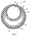
図1および図2は近位シャフト102の一実施形態の断面を例示している。図1は、近位シャフト部102が遷移部106と合流する位置を例示している。しかし、図2は、図1の線II−IIに沿って破断した近位シャフトの断面を例示している。
1 and 2 illustrate a cross section of one embodiment of the
図1および図2で分かるように、近位シャフト部102は、図2の断面図で見ると、略円形の外面129を設けた押出シャフト128を備えている。押出シャフト128は、第1の内面231により、略円形のガイドワイヤ管腔230を定めている。押出シャフト128はまた、第2の内面133により、弧状の膨張管腔132を定めている。膨張管腔132の湾曲形状はその上にガイドワイヤ管腔230を設置しているため、近位シャフト102は全体が略円形状の断面を有している。
As can be seen in FIGS. 1 and 2, the
代替の実施形態では、ガイドワイヤ管腔は弧状であるが、膨張管腔は略円形であることを、当業者なら認識できる。しかし、弧状のガイドワイヤ管腔よりもむしろ、円形状のガイドワイヤ管腔を通してガイドワイヤを追従するほうが、より容易である。膨張管腔132は、遠位端のバルーン(図示せず)と膨張液を流体連絡状態にするように機能するため、バルーンを膨張させるのに十分な流体を中に通すことができるのであれば、膨張管腔はどのような形状を呈していてもよい。
One skilled in the art will recognize that in alternative embodiments, the guidewire lumen is arcuate, while the inflation lumen is generally circular. However, it is easier to follow the guidewire through a circular guidewire lumen rather than an arcuate guidewire lumen.
図1および図2に例示されているような横並びの管腔配置は、OTWカテーテルシャフトタイプまたはMXカテーテルシャフトタイプに特に好適である。図2の近位シャフト部102の実施形態はMXカテーテルシャフトであるが、それは、ガイドワイヤがガイドワイヤ管腔230から外に出ることができるようになる前に中を通ることになる長手方向の切り込み134が設けられているからである。OTWカテーテルシャフトは図2のものに類似しているが、例外として、長手方向の切り込み134が存在していない。略円形断面のカテーテルシャフト100は、肉体管腔の断面も略円形状であれば、容易にその肉体管腔を縦断する。従って、図2の構造を設けたOTWカテーテルまたはMXカテーテルは、もっと小さいプロファイルを有していることもあり、長円形断面または楕円形断面の従来のOTWカテーテルまたはMXカテーテルと比較して、肉体管腔を通して操舵するのが容易となる。
A side-by-side lumen arrangement as illustrated in FIGS. 1 and 2 is particularly suitable for the OTW catheter shaft type or the MX catheter shaft type. The embodiment of the
RXカテーテルは単一管腔の近位シャフト部を備えており、これは、カテーテルシャフト100の極めて遠位の部分にのみガイドワイヤ管腔が設けられているせいである。RXカテーテルでは、図2に例示されている断面が現れるのは、近位シャフト部のまさに最遠位部か、または、遠位部もしくは遷移部だけである。
RX catheters have a single lumen proximal shaft portion, because the guidewire lumen is provided only at the very distal portion of the
当業者なら、後段に記載されているような本発明の遷移部と多様な遷移手段が固定ワイヤ、OTWカテーテルタイプ、RXカテーテルタイプ、または、MXカテーテルタイプに好適となるにはどのようにすればよいかを認識することができる。 Those skilled in the art should know how to make the transition part and various transition means of the present invention as described below suitable for fixed wire, OTW catheter type, RX catheter type, or MX catheter type. Can be recognized.
本発明の実施形態では、近位シャフト部102は補強手段により補強される。補強手段は近位シャフト部102の押し自在性を向上させる。換言すると、補強手段が近位シャフト部102の硬度を高めているため、使用者はカテーテルを制御しながら、同時に、体内管腔の曲がりくねった経路を近位位置から右に左にと縦走させることができる。一実施形態では、補強手段は、近位部シャフト102の全長に沿って使用される。
In an embodiment of the invention, the
従来のカテーテルでは、補強手段はステンレス鋼のハイポチューブのような細い金属管で、近位シャフト部を補強するために、ガイドワイヤ管腔または膨張管腔に挿入される。しかし、MXカテーテル設計は、ガイドワイヤ管腔内にハイポチューブを挿入させるのには不向きである。その理由は、ガイドワイヤは、図2に例示されているように、押出シャフト128のガイドワイヤ管腔と外面129の間に設けられた長手方向切り込み134から外へ逃れ出ることができなければならないからである。しかし他方で、未修正のハイポチューブは、膨張管腔が円形ではなくて弧状であるので、図2に例示されている膨張管腔で使用するのに好適とは言えない。従って、本発明の実施形態は異なるタイプの補強手段を備えている。
In conventional catheters, the reinforcing means is a thin metal tube, such as a stainless steel hypotube, which is inserted into the guidewire lumen or inflation lumen to reinforce the proximal shaft portion. However, the MX catheter design is not suitable for inserting a hypotube into a guidewire lumen. The reason is that the guidewire must be able to escape out of a
図2は弧状の補強手段135を例示している。弧状の補強手段135は、特定の円弧形状に鋳造された管材であってもよいし、または、ハイポチューブのような細い管であって、円弧形状を形成するように、クリンプ(かしめ)加工されたものであってもよい。或いは、変形例として、補強手段135は、剛性に富むプラスチック材料であってもよい。
FIG. 2 illustrates an arcuate reinforcing
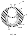
図3Aから図3Cは補強手段の更に別な実施形態を示している。補強手段335A、335B、および、335Cは、平坦な形状、湾曲形状、または、円筒形状の金属製または重合体製の板材または棒材である。金属が使用される場合、補強手段335A、335Bは、ステンレス鋼、チタニウム、タングステン、ニチノール、または、医療装置に使用するのに好適な上記以外の何らかの好適な金属で構成することができる。補強手段335A、335B、または、335Cが湾曲している場合、これらの補強手段はプレス加工により成形され、ハイポチューブから切り出され、或いは、押出し成形により湾曲形状にすることができる。未修正のハイポチューブ以外の補強手段を設ける利点は、図3Aに例示されているもののような棒材または板材を使うと、膨張管腔132の内側の空間的余裕で利用できないように塞いでしまう部分が少なくなるため、管腔内を通してより大量の膨張液を通過させることができるという点である。更に、完全に管状の補強手段の2重壁を欠いているため、カテーテルシャフト100の全体的寸法を低減することができるので、この実施形態はプロファイルを減じたカテーテルに好適である。図3Aに例示されているこの種の補強手段はまた、ガイドワイヤ管腔を通るガイドワイヤの運動に干渉しないのであれば、または、MXカテーテルタイプの長手方向切り込み134を通ってガイドワイヤが外へ出ることに干渉しないのであれば、略円形のカテーテルシャフト100のガイドワイヤ管腔に挿入することもできる。
3A to 3C show a further embodiment of the reinforcing means. The reinforcing means 335A, 335B, and 335C are a flat plate, a curved plate, or a cylindrical plate or bar made of metal or polymer. When metal is used, the reinforcing means 335A, 335B can be comprised of stainless steel, titanium, tungsten, nitinol, or any other suitable metal suitable for use in medical devices. When the reinforcing means 335A, 335B, or 335C is curved, these reinforcing means can be formed by pressing, cut out from a hypotube, or formed into a curved shape by extrusion. The advantage of providing reinforcing means other than an unmodified hypotube is that if a bar or plate such as that illustrated in FIG. 3A is used, it will be blocked from being available due to the spatial margin inside the
図3Bおよび図3Cは、弧状の膨張管腔132の内側に設置するための補強手段のまた別な実施形態を例示している。図3Bは部分的なハイポチューブ補強手段335Bも構成要素の一部として描いているが、ここでは、頂面部のみがハイポチューブから削り取られている。ハイポチューブの一部を除去した結果、補強手段335Bは略C字型断面を有するようになる。修正後のハイポチューブの形状で、ガイドワイヤ管腔の一部が管の内部に侵入することができるようにした結果、全体的なシャフトのプロファイルを低減することができた。更に、修正後のハイポチューブを使用することで、全体的なシャフトのプロファイルを低減することができると同時に、容易に利用できる素材を提供している。
3B and 3C illustrate yet another embodiment of a reinforcing means for placement inside the
図3Cの実施形態は、2部構成である補強手段335Cを含んでいる。この2部構成の補強手段335Cは第1の補強部材370と第2の補強部材372を備えている。第1の補強部材370は概ね管状であり、その壁の一部が除去されている。このように、第1の補強部材370は細長い部分的な環体を形成している。第2の補強部材372は全体が、湾曲した板材として形成されているが、その代替例として、管材の一部であってもよい。ガイドワイヤ管腔230と膨張管腔132の間の空間が最小限になるように、第2の補強部材の壁の厚さは、第1の補強部材の壁の厚さよりも短くなっているのが好ましい。
The embodiment of FIG. 3C includes reinforcing means 335C that is a two-part configuration. This two-part reinforcing means 335 </ b> C includes a first reinforcing
補強手段335Cを形成するために、第1の補強部材370と第2の補強部材372は、弧状の管を形成するように機械接合されている。結合されることで、第2の補強部材372の湾曲は第1の補強部材370の湾曲に概ね平行になるように修正され、第2の補強部材372は一部が環状の第1の補強部材370の空隙を橋渡ししている。
In order to form the reinforcing means 335C, the first reinforcing
使用時には、補強手段335Cは膨張管腔132の壁を形成しており、また、ガイドワイヤ管腔230の壁の一部を形成することができる。その結果、第1の補強部材370と第2の補強部材372の結合は、カテーテルおよび補強手段335Cを屈曲させたと捩ったりしている最中に接合部に発生することになる力に耐えるのに十分な強度を有していなければならない。更に、補強手段335Cは、補強手段335Cを通って移動する膨張液が逃れることができなくなるように、液体密封状態にされるべきである。
In use, the reinforcing means 335C forms the wall of the
第1の補強部材370と第2の補強部材372は金属製であってもよいし、或いは、重合体製であってもよい。第1の補強部材370と第2の補強部材372を機械的に連結するために、この方法は各種の特殊な素材ごとに別あつらえにされるべきである。このような方法として、粘着剤による接着、重ね接合熱圧縮接着、レーザー溶接、超音波溶接、または、金属同士または重合体同士を接着するための当該技術で周知の上記以外の方法が挙げられる。
The first reinforcing
補強手段335Cは、カテーテル部に挿入する前に構成されるのが好ましい。補強手段335Cは、形成後に、既に押出し成形されたカテーテル部に挿入されてもよいし、または、カテーテル部が補強手段335Cの上を覆うように押出し成形されるようにしてもよい。これ以外にも多様な形状の、同じように補強された膨張管腔132が本発明で利用するのに適しているのが分かる。
The reinforcing means 335C is preferably configured before being inserted into the catheter portion. The reinforcing means 335C may be inserted into the already extruded catheter part after formation, or may be extruded so that the catheter part covers the reinforcing means 335C. It will be appreciated that variously shaped, similarly reinforced
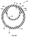
図4Aおよび図4Bに描かれているまた別な実施形態では、補強手段435は押出シャフト128に埋設されている。図4Aでは、補強手段435はステンレス鋼ハイポチューブの半分体のような2分の1管であり、これは、ガイドワイヤ管腔230の反対側に位置する膨張管腔132の辺に接している押出シャフト128の一部437の中に押出し成形されたものである。これに代わる例として、補強手段は押出シャフト128の別な部分の中に押出し成形されていてもよい。例えば、補強手段はガイドワイヤ管腔230と膨張管腔132の間の部分439に配置されていてもよい。また、図4Bに例示されているように、支持ストリップ436A、436Bは、ガイドワイヤ管腔230に丁度隣接している別な位置438A、438Bに設置される。支持ストリップ436A、436Bは補強手段435と一緒に押出し成形されてもよいし、或いは、該補強手段の代替物として成形されてもよい。更に、支持ストリップ436A、436Bのどちらでも一方だけが押出シャフト128の中に埋設されるようにしてもよい。同軸OTWカテーテル、固定ワイヤカテーテル、RXカテーテルのような上記以外のカテーテル設計は、近位シャフト部102の押出シャフト128の中に押出し成形された補強手段を設けるようにしてもよい。
In yet another embodiment depicted in FIGS. 4A and 4B, the reinforcing means 435 is embedded in the
図2、図3A、図3B、図4A、図4Bは、本発明に従って近位シャフト部を補強することができる幾つかの方法を提供してきたにすぎない。本発明は、上記以外の補強技術を利用した用途に好適になるようにしてもよい。 2, 3A, 3B, 4A, and 4B have only provided several ways in which the proximal shaft portion can be reinforced in accordance with the present invention. The present invention may be suitable for applications using reinforcement techniques other than those described above.
図1では、遠位シャフト部104の同軸構造体が遷移部106の中で延びていることで、押出シャフト128が外側シャフト部124の中に挿入されて接着されるようになっている。同様に、内側シャフト122は、近位シャフト部102の近位ガイドワイヤ管腔230に挿入され、そこに接着される。しかしながら、代替の実施形態では、近位シャフト部102の押出シャフト128は、補強手段135によって供与される付加的な支持が無くても、遷移部106の中で遠位方向に延びている。例えば、図9はこのような遷移部を例示しており、後段で詳細に説明されるとおりである。
In FIG. 1, the coaxial structure of the
図1でわかるように、近位シャフト部102の遠位端110は補強手段135の遠位端138と同時に現れる。カテーテルシャフト100の最遠位端は非常に可撓性に富み、血管系の極めて曲がりくねった各部を廻って湾曲しなければならない。しかしながら、図1の補強手段135によって設けられた硬さが突然に終端することで、カテーテルシャフト100に処置途上で酷い捩れが生じることがある。従って、遷移部106は補強手段135の遠位端138から遷移手段114の遠位端116まで延在し、近位シャフト部102の硬い部分と遠位シャフト部104の可撓性に富む部分の間に変遷部分を設けている。
As can be seen in FIG. 1, the
従来のカテーテルシャフトでは、遷移手段は補強手段を螺旋状に切り込むにより作成される。しかし、この場合の補強手段は円形のハイポチューブではないので、本発明は補強手段を螺旋状に切り込む手段の代替例となる遷移手段を提供する。 In conventional catheter shafts, the transition means is created by cutting the reinforcing means in a spiral. However, since the reinforcing means in this case is not a circular hypotube, the present invention provides a transition means that is an alternative to the means for cutting the reinforcing means in a spiral.
図1では、遷移手段114は渦巻き状の螺旋部140である。渦巻き状の螺旋部140はコイルを形成するように捻転された金属ワイヤまたは金属リボンから作成される。これに代わる例として、渦巻き状の螺旋部140は、遷移部106に支持を供与するのに十分な強度を有している熱可塑性重合体から作成することができる。渦巻き状の螺旋部140はワイヤリボンであるのが好ましいが、このリボンは平坦に置かれて、押出し成形時に外側シャフト124の中に埋設されることになるが、但し、外側シャフト部124の外径を著しく増大させることがない。渦巻き状の螺旋部140を押出し成形されている外側シャフト部124の中に埋設させることで、個別に存在する構成要素の数が減るせいで、カテーテルシャフト100の組立てを容易にすることができる。更に、カテーテルシャフトは平滑な外壁面を維持しており、体内管腔を通って移動するのを補助している。
In FIG. 1, the transition means 114 is a
渦巻き状の螺旋部140は、近位端108付近ほどコイルのピッチがより緊密に寄せ合わせて、かつ、遷移部106の遠位端116付近ほどピッチが、より互いから遠ざかるようにすることにより、可撓性を徐々に増大させている。更に、渦巻き状の螺旋部140に沿って遠位方向に進むほど、コイルの巻き線は互いから一層遠ざかるようになる。コイルの巻き線同士が密に寄り合うほど、渦巻き状の螺旋部140は移動が少なくなり、従って、遷移部106の硬度を増すことになる。しかし、コイルの巻き線同士が互いから遠ざかるほど、渦巻き状の螺旋部140は移動が多くなり、可撓性も増す。よって、渦巻き状の螺旋部140は遷移部106に沿って可撓性の漸進的変遷を供与している。更に、渦巻き状の螺旋部140の長さはどのようなものでもよく、ピッチは、遷移部106に沿った特定の位置で所望の可撓性を発現するように変更することができる。
The
代替の実施形態では、押出シャフト128は、補強手段135が無くても遷移部106の中に延びて入る。従って、遷移手段114は外面124に配置されるが、その位置は、押出シャフト128と外側シャフト部124が重畳している場所である。これに代わる例として、渦巻き状の螺旋部140は、補強手段135の遠位端138より遠位の位置で、押出シャフト128の中に押出し成形される。
In an alternative embodiment, the
図5は、本発明の代替の実施形態の外部の斜視図を例示している。図5は、図1について前段で論じたように、近位シャフト部102、遠位シャフト部104、および、遷移部106から構成されている。例えば、近位シャフト部102は線II−IIに沿って破断された断面を有しているが、これは、図2から図4に例示されている断面のいずれかの形態を取るようにしてもよいし、或いは、別な種類の補強手段を備えているようにしてもよい。
FIG. 5 illustrates an external perspective view of an alternative embodiment of the present invention. FIG. 5 is comprised of a
しかしながら、図5は、外側シャフト部124に埋設されているよりは、むしろ、その外面544に設置された遷移手段114として、渦巻き状の螺旋部540を描いている。ここでもまた、渦巻き状の螺旋部540はコイル状リボンまたはコイル状ワイヤであるが、リボンであるのが好ましく、外側シャフト部124の外面544に支持されて平坦に置かれている。
However, FIG. 5 depicts a
図6は、図5の線VI−VIのところで破断された遷移部106の断面図を示している。図6は、ガイドワイヤ管腔120を定める内側シャフト122を含む遷移部106を例示している。遷移部106はまた、内側シャフト部122と外側シャフト部124の間の領域によって定められた膨張管腔126を有している。図6は、外面544と幾分か同一平面に保つことにより、リボンの渦巻き状の螺旋部540がどのように小さい外径642を設けているかを例示している。ワイヤの渦巻き状の螺旋部540は、図6に例示されている略矩形の断面よりもむしろ、丸みを帯びた断面を有している。図6はまた、外側シャフト124の外面544に陥凹部646が設けられており、この部分が渦巻き状の螺旋部540を受け入れて、より小さい外径642を設けるようにしてもよい。レーザーで外面544上に陥凹部646を高精度に線引きするようにしてもよいし、または、陥凹部646が柔らかい重合体面上に刻印されてもよい。渦巻き状の螺旋部540は、粘着剤接着、熱溶着、レーザー接着、締り嵌め、または、それ以外のタイプの接着によって、渦巻き状の螺旋部540の全長に沿って外面544に固着される。
FIG. 6 shows a cross-sectional view of the
これに代わる例として、渦巻き状の螺旋部540は、外側シャフト部124の外面544に沿って全部または一部が自由移動式になっている。このように、渦巻き状の螺旋部540の一部または一端のみが外側シャフト部124の外面544に接着される。完全にまたは一部が自由移動式の渦巻き状の螺旋部540は遷移部106により高い可撓性を供与することができるが、体内管腔への挿入時に、体内管腔の壁により大きな摩擦を生じることがある。これに代わる例として、渦巻き状の螺旋部540は、外面544とポリオレフィン層、ポリイミド層、または、ポリアミド層のような薄い被膜または被覆との間に設置され、体内管腔を通して移動する際の摩擦を低下させ、渦巻き状の螺旋部540を適所に保持することができる。
As an alternative example, the
渦巻き状の螺旋部540は近位端548から遠位端516までピッチ(すなわち、互いに隣接し合う巻き線同士の間の距離)が変動する。特に、近位端548付近では、渦巻き状の螺旋部540は緊密なピッチにされており、この場合、巻き線同士は互いに密に寄り合っている。遠位端516では、渦巻き状の螺旋部540のピッチはもっと緩く、巻き線同士は互いからの距離がより広くなっている。従って、近位端548から遠位端516まで、渦巻き状の螺旋部540の可撓性はコイルのピッチが大きくなるにつれて増大し、遷移部106の可撓性を漸進的に増大させている。
The
図7は、本発明のまた別な実施形態を例示している。図7は、図1のカテーテルシャフト100に類似しているカテーテルシャフト700に近位シャフト部702と、遠位シャフト部704と、遷移部706とが設けられているのを例示している。近位シャフト部702は線II−IIに沿って破断された断面を有しており、この断面は、図2から図4に示されている断面のいずれかの形態を呈しているか、または、別なタイプの補強手段を含んでいるようにしてもよい。図7の実施形態では、遷移手段714は、外側シャフト部724と内側シャフト部722の間に設置された渦巻き状の螺旋部740である。換言すると、渦巻き状の螺旋部740は膨張管腔726の内側に配置されている。
FIG. 7 illustrates yet another embodiment of the present invention. FIG. 7 illustrates that a
渦巻き状の螺旋部740は近位端748で近位シャフト部702に接着されている。そういう場合は、渦巻き状の螺旋部740の遠位端716は外側シャフト部724の内側では自由移動式であってもよい。これに代わる例として、渦巻き状の螺旋部740は、その1箇所またはそれ以上の場所で、または、その全長尺に沿って外側シャフト部724の内面750に接着されていてもよい。例えば、渦巻き状の螺旋部740の遠位端716は外側シャフト部724に接着されており、近位端748は自由移動式であるようにしてもよい。渦巻き状の螺旋部740はまた、外側シャフト部724と被膜または被覆との間に配置されるようにしてもよいが、この被膜または被覆は、渦巻き状の螺旋部740を適所に保持し、かつ、渦巻き状の螺旋部740を膨張液流から隔絶するために使用される。また別な実施形態では、図7に示されている渦巻き状の螺旋部740よりも外径が小さく、図5および図6に示されているような外側シャフト部124を押圧している渦巻き状の螺旋部540に類似した様式で内側シャフト部722の外面を支持して平たく置かれるようにした、渦巻き状の螺旋部が使用される。
A
上述のように、近位端748から遠位端716まで、渦巻き状の螺旋部740の可撓性は巻き線同士の間のピッチが増大するに連れて大きくなり、遷移部706の可撓性を徐々に増大させている。
As described above, from the
ここでもまた、自由移動式である渦巻き状の螺旋部は最大の可撓性を供与するようになる。しかし、図7の渦巻き状の螺旋部740は、近位シャフト部702のどの部分にも、または、遷移部706のどの部分にも接着されていなければ、外側シャフト部724の内部を近位方向または遠位方向に移動することがある。しかし、図8は本発明のまた別な実施形態を示しており、図7とほぼ同一であるが、例外として、外側シャフト部824の直径が第1の径856から第2の径858へと低減する、直径が「突き当たって」減少した領域854が外側シャフト部824に設けられている。第2の径858は渦巻き状の螺旋部840の直径よりも短く、従って、渦巻き状の螺旋部840が外側シャフト部824の内側を近位方向と遠位方向に移動しないようになっている。図8のカテーテルシャフト800では、渦巻き状の螺旋部840は自由に移動して最大限の可撓性を得ることができる。
Again, the spiral helix, which is free-moving, provides maximum flexibility. However, if the
図1に例示されているようなカテーテルシャフト100など、上述の各実施形態のカテーテルシャフトがMXカテーテル設計で利用されている場合には、近位シャフト部102の長手方向の切り込み134は渦巻き状の螺旋部140まで達することができるようになるにすぎず、というのも、渦巻き状の螺旋部は遷移部106の内側または外側のいずれかを廻って閉じた1重ループを形成するからである。従って、MXカテーテルは、渦巻き状の螺旋部140の位置付近またはそれより遠位で長手方向の切り込み134を開くことができなくなる。これは、前述の各実施形態の渦巻き状の螺旋部について言えることである。
When the catheter shaft of each of the embodiments described above is utilized in an MX catheter design, such as the
図1を参照すると、MXカテーテルのガイド部材(図示せず)は長手方向の切り込み134を開き、ガイドワイヤ管腔230からガイドワイヤを外に導く。しかし、カテーテルシャフト100が容易に交換できるようにするためには、操作主がガイドワイヤの近位部を保持したままでカテーテルシャフト100より遠位の位置にガイドワイヤを到達させることができるのに十分な距離だけ、カテーテルシャフト沿いに遠位方向にガイド部材が移動しなければならない。従って、近位シャフト部102の遠位端110(すなわち、長手方向の切り込み134が終端している位置)は、MXカテーテルが作動するように機能するのに十分なだけカテーテルシャフト100の遠位端に近い位置にあるようにしなければならない。しかしながら、上述の実施形態の各々に記載されていたように、遷移手段としての閉ループの渦巻き状の螺旋部はどの位置でも、OTWカテーテル、固定ワイヤカテーテル、および、大半のRXカテーテルとの併用に十分に好適である。
Referring to FIG. 1, a guide member (not shown) of the MX catheter opens a
図9は本発明の別な実施形態を例示している。図9のカテーテルシャフト900もまた、近位シャフト部902と、遠位シャフト部904と、遷移部906とを含んでいる。また、近位シャフト部902は、図2から図4に示されている断面のうちのいずれかの形態を呈している、線II−IIに沿って破断された断面を有していてもよいし、または、別なタイプの補強手段を備えていてもよい。この場合、押出シャフト928は遷移部906の中に延びている。この実施形態では、遷移手段914は本質的に補強手段935の一部940であり、ここでは、補強手段の構造の一部が遷移部906の長尺に沿って漸進的に取除かれている。例えば、図9では、補強手段935の近位部は弧状の管であり、これは図2に示されているとおりである。しかし、近位シャフト部902の遠位端910より遠位では、補強手段935は寸法と形状が低減されて、より薄く、かつ、より可撓性に富むようになっている。この場合、補強手段935は削り取られて、遷移部906の遠位端912付近ではほぼ消滅するまでになっていてもよい。補強手段935が低減されるにつれて、補強手段が近位シャフト部902に供与していた硬さも低減される。従って、遷移部906は徐々に可撓性を増してゆく。
FIG. 9 illustrates another embodiment of the present invention. The
補強手段935の形状と厚さは、遷移部906の長尺沿いのどの位置にも所望の可撓性を達成するように、補強手段935の低減部940に沿って、多様な方法で変更することができる。例えば、補強手段935が棒材または金属材である場合は、棒材または金属板材は、それが補強手段として使用されている近位端におけるよりも、遠位端において、より薄く、かつ、より可撓性に富むようにされてもよい。
The shape and thickness of the reinforcing means 935 can be varied in various ways along the reduced
これに代わる例として、補強手段935の各種特性は、補強手段935の物理的寸法の変動が無い場合でも、部分940ごとに変動させることができる。例えば、補強手段935は熱可塑性重合体から作成され、近位シャフト部902に特定の硬度をもたせている。しかし、遷移部906では、そのような重合体の各種特性を化学的に変動させて、遷移部906に沿って可撓性を徐々に高めることができる。例えば、遷移部906は異なる硬度構成を有する2種類の素材からなり、各素材ごとの濃度(すなわち、パーセント濃度)が遷移部906の長尺に沿って変動して、異なる特性をもたらすようにしてもよい。更に、架橋結合のような化学処理で遷移部906に沿った特性を変動させるようにしてもよい。
As an alternative example, the various characteristics of the reinforcing means 935 can be varied from
図10および図11は、線X−Xと線XI−XIに沿ってそれぞれに破断された、遷移部906の断面図である。図10および図11は補強手段935の部分940の漸進的な低減を例示しており、これは図9に仮想線で示されている。
10 and 11 are cross-sectional views of the
図9の実施形態は、長手方向の切り込み934を利用して、ガイドワイヤ管腔930内で近位シャフト部902と遷移部906の両方の長尺に沿って、少なくとも外側シャフト部924が押出シャフト928に重畳している位置までガイドワイヤを接近させることができるのを例示している。従って、ガイド部材(図示せず)は、遠位シャフト部924に本質的に到達するまで、近位シャフト部902の長手方向の切り込み934に沿って遠位方向に滑動させられる。このように操作することで、ガイドワイヤはガイドワイヤ管腔930の遠位部を実効的に短くし、ガイドワイヤが近位方向のガイド部材に接近できるようにするとともに遠位方向のカテーテル900の遠位先端部に接近できるようにすることで、操作主がカテーテルを1回で交換できるようにしている。長手方向の切り込み934付近の或る箇所を除いて、膨張管腔932、ガイドワイヤ管腔930、または、押出シャフト928内部のどこにでも設置できる平坦な補強部材または湾曲した補強部材ならば、長手方向の切り込み934にガイド部材を接近させることができるようになる。
The embodiment of FIG. 9 utilizes a
図12は本発明のまた別な実施形態を例示している。この実施形態では、カテーテルシャフト1200は近位シャフト部1202、遠位シャフト部1204、および、遷移部1206から構成されている。この場合、押出シャフト1228は図9の遷移部に類似している遷移部1206の中に延びている。しかし、補強手段1235は近位シャフト部1202の遠位端1210を越えて更に遠位方向に延びることは無い。従って、ガイドワイヤ管腔、膨張管腔1232、および/または、押出シャフト1228は、遷移部1206の範囲内にそれぞれの補強手段を内在させていない。図12では、遷移手段1214はU字型スリーブ1240である。図12のU字型スリーブ1240は、押出シャフト1228の外面1229の上に配置されている。U字型スリーブは上述の渦巻き状の螺旋部の利点を有してはいるが、カテーテルシャフト1200を廻る全周囲を包むものではない。従って、U字型スリーブ1240には開口1260が設けられており、ガイド部材によって遷移部1206の遠位端1212付近の位置まで長手方向の切り込み1234が出入り自由にされる。
FIG. 12 illustrates yet another embodiment of the present invention. In this embodiment, the
U字型スリーブ1240は、そのあらゆる位置で、または、その全長に沿って、粘着剤接着、熱接着、レーザー接着、または、それ以外の種類の接着により押出シャフト1228の外面1229に接着される。渦巻き状の螺旋部のものと同様に、自由移動式のU字型スリーブ1240は遷移部1206の可撓性をより向上させることができるが、肉体管腔への挿入時の肉体管腔の壁との間に生じる摩擦が大きくなりがちである。U字型スリーブ1240は外面1229と、ポリオレフィン層またはポリイミド層のような薄い皮膜または被覆との間に設置されて、肉体管腔を通って移動している間の摩擦を低減するとともに、U字型スリーブ1240を適所に保持することができる。これに代わる例として、U字型スリーブ1240は押出シャフト1228の中に押出されるようにしてもよい。
The
図13は、図12の線XIII−XIIIにおける遷移部1206の断面を例示している。図13は、ガイドワイヤ管腔1230および膨張管腔1232を定める押出シャフト1228を例示している。図13は、U字型スリーブ1240が外面1229と幾分同一平面に保つことによりどのように小さい外径1342にすることができるかを例示している。図13はまた、押出シャフト1228の外面1229にどのようにして陥凹部1346を設けることができるかを例示しているが、このような陥凹部はU字型スリーブ1240を受け入れて、より小さい外径1342にすることもできる。図13はまた、U字型部材1240の開口1268を例示しているが、この開口を通ってガイド部材は移動し、長手方向の切り込み1234を出入り自由にするとともに、ガイドワイヤ管腔1230の内側に設置されたガイドワイヤを放出する。
FIG. 13 illustrates a cross section of the
U字型スリーブ1240はリボンまたはワイヤから形成される。代替例として、U字型スリーブ1240は、遷移部1206を支持するのに十分な強度が設けられた熱可塑性重合体から作成される。U字型スリーブ1240はワイヤリボンであるのが好ましい。図13に例示されているように、ワイヤの丸みを帯びた断面よりも平坦な断面を有しているリボンのほうが、カテーテルシャフト1200の外径1342を小さく設けることができる。
The
図14は、リボンまたはワイヤ1460が折り曲げられて、繰り返し連続するループ1464となって、概ね正弦波様の形状、または、ジグザグ形状を呈しているのを例示している。ループ1464は図14に例示されているような形状であってもよいが、この場合、ループ1464同士の間のピッチとループの寸法は、リボン1460沿いに進むにつれて増大する。ループ1466は小さいほど、それよりも大型のループ1468が供与できるほどの大きい可撓性を遷移部1206にもたらすことができない。従って、ループ1468が大きいほど、U字型スリーブ1240の遠位端1416に近づくが、この場合、より高い可撓性が要求される。図14のリボン1460は成形ツール上でリボンまたはワイヤを折り曲げることにより形成される。これに代わる例として、リボンまたはワイヤ1460は金属板材またはプラスチック板材から打抜き加工されてもよい。
FIG. 14 illustrates the ribbon or
図15は、図14のリボンまたはワイヤ1460がどのように折り曲げられてU字型スリーブ1240を形成するのかを例示している。U字型スリーブ1240は、全体的に、軸線1565を中心として湾曲しているが、この軸線は略円形カテーテルシャフト1200の中心点である。ループ1464は上に折り曲げられて、図14のループの両端が図15では同じ方向を向くか、または、互いに対向し合うが、これは、U字型スリーブがどのぐらい離して湾曲されるかによって決まる。U字型スリーブ1240はカテーテルシャフト1200の上を滑動させられてから、遷移部1206の押出シャフト1228の外面1229上でかしめられるが、これは図13に描かれているとおりである。代替例として、U字型スリーブ1240は、図14のリボン形状またはワイヤ形状1460から直接、押出シャフト1228上に折り曲げられてもよい。
FIG. 15 illustrates how the ribbon or
本発明をその好ましい実施形態に言及しながら特に例示し、説明してきたが、このような実施形態は具体例として提示されたにすぎず、何ら限定するものではなく、本発明の精神および範囲から逸脱せずに、このような実施形態の形態と細部に多様な変更を施すことができることが、当業者には分かる。 While the invention has been particularly illustrated and described with reference to preferred embodiments thereof, such embodiments have been presented by way of example only and are not intended to be limiting in any way, from the spirit and scope of the invention. Those skilled in the art will recognize that various changes can be made in the form and details of such embodiments without departing.
従って、本発明の外延と範囲は上述の具体的な実施形態のいずれによっても限定されるべきではなく、添付の特許請求の範囲の各請求項とそれらの均等物によってのみ限定されるべきである。更に、本明細書中で引例に挙げられている参考文献は全て、交付済みの米国特許とそれ以外の参考文献を含め、引例に挙げることにより各々の全体が本件の一部をなしているが、引例に挙げられた参考文献に提示されている全てのデータ、表、図、文章を指す。 Accordingly, the extension and scope of the invention should not be limited by any of the specific embodiments described above, but only by the claims of the appended claims and their equivalents. . Furthermore, all references cited in this specification, including issued U.S. patents and other references, are each incorporated by reference in their entirety. , Refers to all data, tables, figures and texts presented in the references cited in the reference.
特殊な実施形態の前述の説明が本発明の一般的性質を明らかにするにあたり、その程度は、過度の実験を行わずとも、本発明の一般的概念から外れることなく、当該技術の範囲内の知識(本件で引例に挙げられた参考文献の内容など)を供与することにより、第三者がそのような特殊な実施形態を容易に修正し、かつ/または、改変することで多様な応用例を得ることができる程度に十分なものである。よって、このような改変や修正は、本明細書に提示されている教示や導きに基づいて、開示された実施形態の均等物の意味と範囲に含まれるものと解釈されるべきである。本明細書の語句表現と用語使用は説明のためであって、限定しようとの目的はないものと理解されるべきであるため、本明細書の用語使用または語句表現は、当業者が、本明細書に提示されている教示および導きを当業者の知識と結合させたことに鑑みて解釈されるべきである。 While the foregoing description of specific embodiments has clarified the general nature of the invention, it should be understood that the extent thereof is within the scope of the art without undue experimentation and without departing from the general concept of the invention. By providing knowledge (such as the content of the references cited in this case), a third party can easily modify and / or modify such special embodiments to achieve a variety of applications. It is enough to obtain. Accordingly, such changes and modifications should be construed as being included within the meaning and scope of equivalents of the disclosed embodiments based on the teachings and guidance presented herein. The terminology and terminology used herein should be understood to be illustrative and not limiting and the terminology or terminology used herein should be understood by those of ordinary skill in the art. It should be construed in view of combining the teachings and guidance presented in the specification with the knowledge of one of ordinary skill in the art.
Claims (18)
ガイドワイヤ管腔および膨張管腔を定めるシャフト部を備え、該シャフト部には、シャフトの外面からガイドワイヤ管腔まで半径方向に延びる長手方向切り込みが設けられており、膨張管腔が弧状の形状になっており、
さらに、第1の肉厚を有するとともに、一部が環状である断面を有している第1の概ね管状の補強部材と、
第1の肉厚よりも薄い第2の肉厚を有する湾曲した細長い補強部材とを備え、該湾曲した細長い補強部材は、第1の概ね管状の補強部材の上に配置されて、第1の概ね管状の補強部材と組み合わされて膨張管腔の壁を形成するとともに、湾曲した細長い補強部材の上面はガイドワイヤ管腔の一部を形成しており、
さらに、シャフト部の上に配置され、かつ、長手方向の切り込みを介してガイドワイヤ管腔と連絡状態になるようにするためのガイド部材を備える、
ことを特徴とするカテーテル。 In the catheter,
A shaft portion defining a guidewire lumen and an inflation lumen, the shaft portion having a longitudinal cut extending radially from the outer surface of the shaft to the guidewire lumen, the inflation lumen having an arcuate shape And
A first generally tubular reinforcing member having a first wall thickness and having a section that is partially annular;
A curved elongate reinforcement member having a second wall thickness less than the first wall thickness, the curved elongate reinforcement member disposed on the first generally tubular reinforcement member, Combined with a generally tubular reinforcement member to form the wall of the inflation lumen, and the upper surface of the curved elongated reinforcement member forms part of the guidewire lumen;
And a guide member disposed on the shaft portion and adapted to communicate with the guide wire lumen via a longitudinal cut.
A catheter characterized by that.
ガイドワイヤ管腔および膨張管腔を定める近位シャフト部を備え、該近位シャフト部は、膨張管腔が弧状の形状になっており、
さらに、膨張管腔の内側に配置された2部構成の補強手段と、
前記近位シャフト部よりも可撓性が大きい遠位シャフト部と、
を備えることを特徴とするカテーテル。 In the catheter,
A proximal shaft portion defining a guidewire lumen and an inflation lumen, the proximal shaft portion having an arcuate shape of the inflation lumen;
A two-part reinforcing means disposed inside the inflation lumen;
A distal shaft portion that is more flexible than the proximal shaft portion;
A catheter comprising:
第1の肉厚、第1の凸状面、および、第1の凹状面を有し、かつ、一部が環状である第1の補強部材と、
第2の肉厚、第2の凸状面、および、第2の凹状面を有する第2の補強部材とを更に備えており、第2の補強部材は、第2の凸状面が第1の凹状面の方を向くようにして第1の補強部材と機械的に連結されており、第1の補強部材と第2の補強部材の組み合わせにより液体密封式の管を形成するようにした、
ことを特徴とする、請求項2に記載のカテーテル。 The two-part reinforcing member is
A first reinforcing member having a first thickness, a first convex surface, and a first concave surface, and a portion of which is annular;
And a second reinforcing member having a second thickness, a second convex surface, and a second concave surface, wherein the second convex member has a first convex surface. It is mechanically connected to the first reinforcing member so as to face the concave surface of the liquid, and a liquid-sealed tube is formed by a combination of the first reinforcing member and the second reinforcing member.
The catheter according to claim 2, wherein:
Applications Claiming Priority (2)
| Application Number | Priority Date | Filing Date | Title |
|---|---|---|---|
| US10/807,434 US20050070879A1 (en) | 2003-09-26 | 2004-03-24 | Transition section for a catheter |
| PCT/US2005/009748 WO2005094932A1 (en) | 2004-03-24 | 2005-03-23 | Transition section for a catheter |
Publications (2)
| Publication Number | Publication Date |
|---|---|
| JP2007530163A true JP2007530163A (en) | 2007-11-01 |
| JP2007530163A5 JP2007530163A5 (en) | 2008-05-08 |
Family
ID=34963894
Family Applications (1)
| Application Number | Title | Priority Date | Filing Date |
|---|---|---|---|
| JP2007505152A Pending JP2007530163A (en) | 2004-03-24 | 2005-03-23 | Catheter transition |
Country Status (4)
| Country | Link |
|---|---|
| US (1) | US20050070879A1 (en) |
| EP (1) | EP1732631A1 (en) |
| JP (1) | JP2007530163A (en) |
| WO (1) | WO2005094932A1 (en) |
Cited By (14)
| Publication number | Priority date | Publication date | Assignee | Title |
|---|---|---|---|---|
| JP2008539973A (en) * | 2005-05-10 | 2008-11-20 | クック・インコーポレイテッド | Catheter reinforcement member |
| JP2012040145A (en) * | 2010-08-18 | 2012-03-01 | Terumo Corp | Medical tube protective cover |
| JP2013180158A (en) * | 2012-03-05 | 2013-09-12 | Sumitomo Bakelite Co Ltd | Medical instrument and method for manufacturing medical instrument |
| JP2014213124A (en) * | 2013-04-30 | 2014-11-17 | 朝日インテック株式会社 | Catheter tube and catheter |
| JP2015504753A (en) * | 2012-01-25 | 2015-02-16 | スミスズ メディカル インターナショナル リミテッド | Tracheostomy tube |
| JP2015134202A (en) * | 2009-06-24 | 2015-07-27 | シファメド・ホールディングス・エルエルシー | Operable medical delivery device and method for using the same |
| JP2016067384A (en) * | 2014-09-26 | 2016-05-09 | テルモ株式会社 | catheter |
| US10188832B2 (en) | 2009-06-24 | 2019-01-29 | Shifamed Holdings, Llc | Steerable delivery sheaths |
| US10420537B2 (en) | 2015-03-27 | 2019-09-24 | Shifamed Holdings, Llc | Steerable medical devices, systems, and methods of use |
| US10933221B2 (en) | 2015-11-09 | 2021-03-02 | Kalila Medical, Inc. | Steering assemblies for medical devices, and methods of use |
| US11052226B2 (en) | 2015-04-24 | 2021-07-06 | Kalila Medical, Inc. | Steerable medical devices, systems, and methods of use |
| WO2023157534A1 (en) * | 2022-02-18 | 2023-08-24 | 株式会社カネカ | Balloon catheter |
| WO2023157533A1 (en) * | 2022-02-18 | 2023-08-24 | 株式会社カネカ | Balloon catheter |
| WO2023157535A1 (en) * | 2022-02-18 | 2023-08-24 | 株式会社カネカ | Balloon catheter |
Families Citing this family (18)
| Publication number | Priority date | Publication date | Assignee | Title |
|---|---|---|---|---|
| US6379334B1 (en) * | 1997-02-10 | 2002-04-30 | Essex Technology, Inc. | Rotate advance catheterization system |
| WO2001023027A1 (en) | 1999-09-27 | 2001-04-05 | Essex Technology, Inc. | Rotate-to-advance catheterization system |
| US8252014B2 (en) * | 2004-03-03 | 2012-08-28 | Innovational Holdings Llc. | Rapid exchange balloon catheter with braided shaft |
| WO2006093976A1 (en) | 2005-02-28 | 2006-09-08 | Spirus Medical Inc. | Rotate-to-advance catheterization system |
| US8317678B2 (en) | 2005-05-04 | 2012-11-27 | Olympus Endo Technology America Inc. | Rotate-to-advance catheterization system |
| US8235942B2 (en) | 2005-05-04 | 2012-08-07 | Olympus Endo Technology America Inc. | Rotate-to-advance catheterization system |
| US8343040B2 (en) * | 2005-05-04 | 2013-01-01 | Olympus Endo Technology America Inc. | Rotate-to-advance catheterization system |
| US8414477B2 (en) * | 2005-05-04 | 2013-04-09 | Olympus Endo Technology America Inc. | Rotate-to-advance catheterization system |
| US7780650B2 (en) | 2005-05-04 | 2010-08-24 | Spirus Medical, Inc. | Rotate-to-advance catheterization system |
| US8435229B2 (en) | 2006-02-28 | 2013-05-07 | Olympus Endo Technology America Inc. | Rotate-to-advance catheterization system |
| US8574220B2 (en) | 2006-02-28 | 2013-11-05 | Olympus Endo Technology America Inc. | Rotate-to-advance catheterization system |
| WO2008144033A2 (en) * | 2007-05-18 | 2008-11-27 | Spirus Medical, Inc. | Rotate-to-advance catheterizaton system |
| US8870755B2 (en) | 2007-05-18 | 2014-10-28 | Olympus Endo Technology America Inc. | Rotate-to-advance catheterization system |
| US8257304B2 (en) * | 2007-06-01 | 2012-09-04 | Tyco Healthcare Group Lp | Extension tubes for balloon catheters |
| JP2009089806A (en) * | 2007-10-05 | 2009-04-30 | Asahi Intecc Co Ltd | Balloon catheter |
| WO2012047803A2 (en) | 2010-10-04 | 2012-04-12 | Reverse Medical Corporation | Distal access aspiration guide catheder |
| US10130789B2 (en) | 2011-06-30 | 2018-11-20 | Covidien Lp | Distal access aspiration guide catheter |
| EP2572749B1 (en) | 2011-09-23 | 2022-04-27 | Covidien LP | Distal access balloon guide catheter |
Family Cites Families (44)
| Publication number | Priority date | Publication date | Assignee | Title |
|---|---|---|---|---|
| US55377A (en) * | 1866-06-05 | Improved means for working ships pumps | ||
| US29362A (en) * | 1860-07-31 | Catamenial bandage | ||
| US4493A (en) * | 1846-05-02 | Improvement in plows | ||
| US3972529A (en) * | 1974-10-07 | 1976-08-03 | Mcneil Walter F | Reinforced tubular materials and process |
| US4748982A (en) * | 1987-01-06 | 1988-06-07 | Advanced Cardiovascular Systems, Inc. | Reinforced balloon dilatation catheter with slitted exchange sleeve and method |
| US4988356A (en) * | 1987-02-27 | 1991-01-29 | C. R. Bard, Inc. | Catheter and guidewire exchange system |
| US6071273A (en) * | 1988-02-29 | 2000-06-06 | Scimed Life Systems, Inc. | Fixed wire dilatation balloon catheter |
| US6004291A (en) * | 1988-02-29 | 1999-12-21 | Scimed Life Systems, Inc. | Intravascular catheter with distal guide wire lumen and transition |
| US5425711A (en) * | 1988-02-29 | 1995-06-20 | Scimed Life Systems, Inc. | Intravascular catheter with distal guide wire lumen and transition member |
| US5156594A (en) * | 1990-08-28 | 1992-10-20 | Scimed Life Systems, Inc. | Balloon catheter with distal guide wire lumen |
| US4960410A (en) * | 1989-03-31 | 1990-10-02 | Cordis Corporation | Flexible tubular member for catheter construction |
| US5019057A (en) * | 1989-10-23 | 1991-05-28 | Cordis Corporation | Catheter having reinforcing strands |
| US5217482A (en) * | 1990-08-28 | 1993-06-08 | Scimed Life Systems, Inc. | Balloon catheter with distal guide wire lumen |
| US5743875A (en) * | 1991-05-15 | 1998-04-28 | Advanced Cardiovascular Systems, Inc. | Catheter shaft with an oblong transverse cross-section |
| WO1995002430A1 (en) * | 1993-07-15 | 1995-01-26 | Advanced Cardiovascular Systems, Inc. | Rapid exchange type intraluminal catheter with guiding element |
| NL9301642A (en) * | 1993-09-22 | 1995-04-18 | Cordis Europ | Microcatheter. |
| US5374215A (en) * | 1993-11-22 | 1994-12-20 | Crider; Brian D. | Vertically adjustable vent cover having venturi cone |
| KR100186950B1 (en) * | 1994-03-10 | 1999-04-01 | 스피겔 알렌 제이 | Catheter having shaft of verying stiffness |
| US5578009A (en) * | 1994-07-20 | 1996-11-26 | Danforth Biomedical Incorporated | Catheter system with push rod for advancement of balloon along guidewire |
| DE69527644T2 (en) * | 1994-11-23 | 2003-04-03 | Micro Interventional Systems I | BALLOON CATHETER WITH HIGH TORQUE |
| US5833672A (en) * | 1994-12-12 | 1998-11-10 | Nippon Zeon Co., Ltd. | Double tube, balloon catheter produced by using double tube, and process for producing balloon catheter |
| DE19534413C1 (en) * | 1995-09-16 | 1997-05-28 | Fresenius Ag | Connection arrangement and method for connecting two individual parts of a medical system |
| US5843050A (en) * | 1995-11-13 | 1998-12-01 | Micro Therapeutics, Inc. | Microcatheter |
| US5906606A (en) * | 1995-12-04 | 1999-05-25 | Target Therapuetics, Inc. | Braided body balloon catheter |
| US5827242A (en) * | 1996-06-21 | 1998-10-27 | Medtronic, Inc. | Reinforced catheter body and method for its fabrication |
| US6186978B1 (en) * | 1996-08-07 | 2001-02-13 | Target Therapeutics, Inc. | Braid reinforced infusion catheter with inflatable membrane |
| US6179825B1 (en) * | 1997-03-15 | 2001-01-30 | Datascope Investment Corp. | Oval vascular catheter |
| US6048338A (en) * | 1997-10-15 | 2000-04-11 | Scimed Life Systems, Inc. | Catheter with spiral cut transition member |
| US6004310A (en) * | 1998-06-17 | 1999-12-21 | Target Therapeutics, Inc. | Multilumen catheter shaft with reinforcement |
| US6059769A (en) * | 1998-10-02 | 2000-05-09 | Medtronic, Inc. | Medical catheter with grooved soft distal segment |
| US20030055377A1 (en) * | 2000-06-02 | 2003-03-20 | Avantec Vascular Corporation | Exchangeable catheter |
| US6585719B2 (en) * | 2001-01-04 | 2003-07-01 | Scimed Life Systems, Inc. | Low profile metal/polymer tubes |
| ATE320830T1 (en) * | 2001-04-17 | 2006-04-15 | Salviac Ltd | CATHETER |
| US6960188B2 (en) * | 2001-11-30 | 2005-11-01 | Abbott Laboratories Vascular Entities Limited | Catheter having enhanced distal pushability |
| US7037291B2 (en) * | 2001-12-04 | 2006-05-02 | Advanced Cardiovascular Systems, Inc. | Catheter shaft junction having a polymeric reinforcing member with a high glass transition temperature |
| US7163524B2 (en) * | 2002-02-27 | 2007-01-16 | Terumo Kabushiki Kaisha | Catheter |
| US6800065B2 (en) * | 2002-04-04 | 2004-10-05 | Medtronic Ave, Inc. | Catheter and guide wire exchange system |
| US20040039372A1 (en) * | 2002-08-21 | 2004-02-26 | Carmody Patrick J. | Over-the-wire catheter having a slidable instrument for gripping a guidewire |
| US6905477B2 (en) * | 2002-09-20 | 2005-06-14 | Medtronic Vascular, Inc. | Catheter with improved transition section |
| US6893417B2 (en) * | 2002-09-20 | 2005-05-17 | Medtronic Vascular, Inc. | Catheter and guide wire exchange system with improved proximal shaft and transition section |
| US20040059369A1 (en) * | 2002-09-20 | 2004-03-25 | Niall Duffy | Catheter and guide wire exchange system |
| US7273485B2 (en) * | 2003-03-20 | 2007-09-25 | Advanced Cardiovascular Systems, Inc. | Balloon catheter having a shaft with a variable stiffness inner tubular member |
| US20040254528A1 (en) * | 2003-06-12 | 2004-12-16 | Adams Daniel O. | Catheter with removable wire lumen segment |
| US20050070847A1 (en) * | 2003-09-29 | 2005-03-31 | Van Erp Wilhelmus Petrus Martinus Maria | Rapid-exchange balloon catheter with hypotube shaft |
-
2004
- 2004-03-24 US US10/807,434 patent/US20050070879A1/en not_active Abandoned
-
2005
- 2005-03-23 JP JP2007505152A patent/JP2007530163A/en active Pending
- 2005-03-23 EP EP05727701A patent/EP1732631A1/en not_active Withdrawn
- 2005-03-23 WO PCT/US2005/009748 patent/WO2005094932A1/en active Application Filing
Cited By (14)
| Publication number | Priority date | Publication date | Assignee | Title |
|---|---|---|---|---|
| JP2008539973A (en) * | 2005-05-10 | 2008-11-20 | クック・インコーポレイテッド | Catheter reinforcement member |
| US10188832B2 (en) | 2009-06-24 | 2019-01-29 | Shifamed Holdings, Llc | Steerable delivery sheaths |
| JP2015134202A (en) * | 2009-06-24 | 2015-07-27 | シファメド・ホールディングス・エルエルシー | Operable medical delivery device and method for using the same |
| JP2012040145A (en) * | 2010-08-18 | 2012-03-01 | Terumo Corp | Medical tube protective cover |
| JP2015504753A (en) * | 2012-01-25 | 2015-02-16 | スミスズ メディカル インターナショナル リミテッド | Tracheostomy tube |
| JP2013180158A (en) * | 2012-03-05 | 2013-09-12 | Sumitomo Bakelite Co Ltd | Medical instrument and method for manufacturing medical instrument |
| JP2014213124A (en) * | 2013-04-30 | 2014-11-17 | 朝日インテック株式会社 | Catheter tube and catheter |
| JP2016067384A (en) * | 2014-09-26 | 2016-05-09 | テルモ株式会社 | catheter |
| US10420537B2 (en) | 2015-03-27 | 2019-09-24 | Shifamed Holdings, Llc | Steerable medical devices, systems, and methods of use |
| US11052226B2 (en) | 2015-04-24 | 2021-07-06 | Kalila Medical, Inc. | Steerable medical devices, systems, and methods of use |
| US10933221B2 (en) | 2015-11-09 | 2021-03-02 | Kalila Medical, Inc. | Steering assemblies for medical devices, and methods of use |
| WO2023157534A1 (en) * | 2022-02-18 | 2023-08-24 | 株式会社カネカ | Balloon catheter |
| WO2023157533A1 (en) * | 2022-02-18 | 2023-08-24 | 株式会社カネカ | Balloon catheter |
| WO2023157535A1 (en) * | 2022-02-18 | 2023-08-24 | 株式会社カネカ | Balloon catheter |
Also Published As
| Publication number | Publication date |
|---|---|
| US20050070879A1 (en) | 2005-03-31 |
| WO2005094932A1 (en) | 2005-10-13 |
| EP1732631A1 (en) | 2006-12-20 |
Similar Documents
| Publication | Publication Date | Title |
|---|---|---|
| JP2007530163A (en) | Catheter transition | |
| JP2007530161A (en) | Transition for catheter | |
| EP3568186B1 (en) | Aspiration catheter systems | |
| US11224450B2 (en) | Aspiration catheter systems and methods of use | |
| US6740104B1 (en) | Enhanced catheter with alignment means | |
| US6780199B2 (en) | Enhanced stent delivery system | |
| US6447501B1 (en) | Enhanced stent delivery system | |
| US10245410B2 (en) | Rapid exchange catheter | |
| US20040133158A1 (en) | Balloon catheter with distal guide wire lumen | |
| EP1083960A1 (en) | Enhanced balloon dilatation system | |
| WO2007047039A2 (en) | Rapid exchange catheter with hypotube and short exchange length | |
| US7189215B2 (en) | Catheter with full-length core wire shaft for core wire interchangeability | |
| US20050070881A1 (en) | Transition section for a catheter | |
| US20220257910A1 (en) | Support catheters and associated loading components |
Legal Events
| Date | Code | Title | Description |
|---|---|---|---|
| A521 | Written amendment |
Free format text: JAPANESE INTERMEDIATE CODE: A523 Effective date: 20080324 |
|
| A621 | Written request for application examination |
Free format text: JAPANESE INTERMEDIATE CODE: A621 Effective date: 20080324 |
|
| A871 | Explanation of circumstances concerning accelerated examination |
Free format text: JAPANESE INTERMEDIATE CODE: A871 Effective date: 20080324 |
|
| A975 | Report on accelerated examination |
Free format text: JAPANESE INTERMEDIATE CODE: A971005 Effective date: 20080421 |
|
| A131 | Notification of reasons for refusal |
Free format text: JAPANESE INTERMEDIATE CODE: A131 Effective date: 20080428 |
|
| A02 | Decision of refusal |
Free format text: JAPANESE INTERMEDIATE CODE: A02 Effective date: 20081006 |