JP2007528239A - Tissue removal apparatus and method - Google Patents
Tissue removal apparatus and method Download PDFInfo
- Publication number
- JP2007528239A JP2007528239A JP2006549535A JP2006549535A JP2007528239A JP 2007528239 A JP2007528239 A JP 2007528239A JP 2006549535 A JP2006549535 A JP 2006549535A JP 2006549535 A JP2006549535 A JP 2006549535A JP 2007528239 A JP2007528239 A JP 2007528239A
- Authority
- JP
- Japan
- Prior art keywords
- fluid
- tissue
- cannula
- energy
- electromagnetic energy
- Prior art date
- Legal status (The legal status is an assumption and is not a legal conclusion. Google has not performed a legal analysis and makes no representation as to the accuracy of the status listed.)
- Pending
Links
Images


Classifications
-
- B—PERFORMING OPERATIONS; TRANSPORTING
- B23—MACHINE TOOLS; METAL-WORKING NOT OTHERWISE PROVIDED FOR
- B23K—SOLDERING OR UNSOLDERING; WELDING; CLADDING OR PLATING BY SOLDERING OR WELDING; CUTTING BY APPLYING HEAT LOCALLY, e.g. FLAME CUTTING; WORKING BY LASER BEAM
- B23K26/00—Working by laser beam, e.g. welding, cutting or boring
- B23K26/0096—Portable laser equipment, e.g. hand-held laser apparatus
-
- A—HUMAN NECESSITIES
- A61—MEDICAL OR VETERINARY SCIENCE; HYGIENE
- A61B—DIAGNOSIS; SURGERY; IDENTIFICATION
- A61B18/00—Surgical instruments, devices or methods for transferring non-mechanical forms of energy to or from the body
- A61B18/18—Surgical instruments, devices or methods for transferring non-mechanical forms of energy to or from the body by applying electromagnetic radiation, e.g. microwaves
- A61B18/20—Surgical instruments, devices or methods for transferring non-mechanical forms of energy to or from the body by applying electromagnetic radiation, e.g. microwaves using laser
-
- B—PERFORMING OPERATIONS; TRANSPORTING
- B23—MACHINE TOOLS; METAL-WORKING NOT OTHERWISE PROVIDED FOR
- B23K—SOLDERING OR UNSOLDERING; WELDING; CLADDING OR PLATING BY SOLDERING OR WELDING; CUTTING BY APPLYING HEAT LOCALLY, e.g. FLAME CUTTING; WORKING BY LASER BEAM
- B23K26/00—Working by laser beam, e.g. welding, cutting or boring
- B23K26/14—Working by laser beam, e.g. welding, cutting or boring using a fluid stream, e.g. a jet of gas, in conjunction with the laser beam; Nozzles therefor
- B23K26/146—Working by laser beam, e.g. welding, cutting or boring using a fluid stream, e.g. a jet of gas, in conjunction with the laser beam; Nozzles therefor the fluid stream containing a liquid
-
- A—HUMAN NECESSITIES
- A61—MEDICAL OR VETERINARY SCIENCE; HYGIENE
- A61B—DIAGNOSIS; SURGERY; IDENTIFICATION
- A61B17/00—Surgical instruments, devices or methods, e.g. tourniquets
- A61B17/32—Surgical cutting instruments
- A61B17/3203—Fluid jet cutting instruments
-
- A—HUMAN NECESSITIES
- A61—MEDICAL OR VETERINARY SCIENCE; HYGIENE
- A61B—DIAGNOSIS; SURGERY; IDENTIFICATION
- A61B2218/00—Details of surgical instruments, devices or methods for transferring non-mechanical forms of energy to or from the body
- A61B2218/001—Details of surgical instruments, devices or methods for transferring non-mechanical forms of energy to or from the body having means for irrigation and/or aspiration of substances to and/or from the surgical site
- A61B2218/007—Aspiration
- A61B2218/008—Aspiration for smoke evacuation
Abstract
電磁誘導型カッターは、霧化流体粒子と相互作用するようにされる。組織除去装置はその吸引カニューレが、電磁誘導による切断力を患者の体内の部位に伝達する流体ガイドおよびエネルギーガイドを収納しており、硬質組織または柔組織を吸引する。カニューレにはカニューレ遠位端が設けられている。カニューレの近位端には、吸引源への流体流接続部が設けられている。分断された硬質組織または柔組織と流体は、カニューレの近位端にある吸引源により、カニューレ遠位端およびカニューレを通して吸引される。硬質組織除去または柔組織除去を目的として、そのようなカッターを使う方法も開示する。
【選択図】図10aThe electromagnetic induction type cutter is adapted to interact with the atomized fluid particles. In the tissue removal apparatus, a suction cannula contains a fluid guide and an energy guide that transmit a cutting force by electromagnetic induction to a site in a patient's body, and sucks hard tissue or soft tissue. The cannula is provided with a cannula distal end. A fluid flow connection to a suction source is provided at the proximal end of the cannula. The severed hard or soft tissue and fluid is aspirated through the cannula distal end and the cannula by a suction source at the proximal end of the cannula. Also disclosed is a method of using such a cutter for the purpose of hard tissue removal or soft tissue removal.
[Selection] Figure 10a
Description
(関連する出願の参照)
本願は、2004年1月8日出願の、「組織除去およびその方法(Tissue Remove and Method)」という名称の米国特許仮出願第60/535,182号の優先権を主張するものであり、該仮出願の内容は、ここに援用することにより、本明細書の一部として組み込まれるのは明らかである。本願は、2003年9月22日出願の「組織除去装置およびその方法(Tissue Remover and Method)」という名称の同時係属中の米国出願第10/667,921号の部分継続出願であり、該部分継続出願は2000年11月15日出願の「組織除去装置およびその方法(Tissue Remover and Method)」という名称の同時係属中の米国特許出願第09/714,479号の継続出願であり、該継続出願は1998年11月6日出願の米国特許出願第09/188,072号の部分継続出願であって、「組織除去装置およびその方法(Tissue Remover and Method)」という名称の現在の米国特許第6,254,597号であるが、上述の出願および特許の全件の内容は、ここに援用することにより、本明細書の一部に組み込まれているのは明らかである。米国出願第09/188,072号は1997年11月6日出願の「脂肪吸引用の電磁誘導型機械カッター(Electromagnetically Induced Mechanical Cutter for Liposuction)」という名称の米国特許仮出願第60/064,465号の優先権を主張するものであり、その内容は、ここに援用することにより、本明細書の一部をなすのは明らかである。米国出願第09/188,072号はまた、1997年12月5日出願の、「電磁誘導型切断処置を目的としたユーザープログラミング可能な霧化粒子の結合(User Programmable Combination of Atomized Particles for Electromagnetically Induced Cutting)」という名称の米国特許出願第08/985,513号の部分継続出願であり、該部分継続出願は、1995年8月31日出願の「電磁誘導型切断処置を目的としたユーザープログラミング可能な霧化粒子の結合(User Programmable Combination of Atomized Particles for Electromagnetically Induced Cutting)」という名称の米国特許出願第08/522,503号の継続出願であり、該継続出願は特許交付を受けて米国特許第5,741,247号となっており、これら出願および特許の内容は、ここに援用することにより、本明細書の一部をなすものであることは明らかである。米国特許出願第09/188,072号はまた、1997年12月17日出願の「流体条件調節システム(Fluid Conditioning System)」という名称の同時係属中の米国特許出願第08/995,241号の部分継続出願であり、該部分継続出願は1995年12月20日出願の「流体条件調節システム(Fluid Conditioning System)」という名称の米国特許出願第08/575,775号の継続出願であり、該継続出願は特許交付を受けて米国特許第5,785,521号となっているが、これら出願および特許のいずれも同一譲受人に譲渡されており、それぞれの内容は、ここに援用することにより、本明細書の一部をなすものであることは明らかである。
(Refer to related applications)
This application claims priority from US Provisional Application No. 60 / 535,182, filed Jan. 8, 2004, entitled “Tissue Remove and Method”. The contents of are hereby expressly incorporated herein by reference. This application is a continuation-in-part of copending US application 10 / 667,921 entitled “Tissue Remover and Method” filed on September 22, 2003, which is a continuation-in-part application. Is a continuation of co-pending US patent application Ser. No. 09 / 714,479 entitled “Tissue Remover and Method” filed Nov. 15, 2000, which was filed in 1998. A continuation-in-part of U.S. patent application Ser. No. 09 / 188,072 filed Nov. 6, which is currently U.S. Pat. No. 6,254,597, entitled “Tissue Remover and Method” It is clear that the contents of all the above-mentioned applications and patents are incorporated herein by reference. US Application No. 09 / 188,072 is the priority of US Patent Provisional Application No. 60 / 064,465 filed Nov. 6, 1997, entitled “Electromagnetically Induced Mechanical Cutter for Liposuction” And the contents of which are hereby expressly incorporated herein by reference. No. 09 / 188,072 is also filed on Dec. 5, 1997, “User Programmable Combination of Atomized Particles for Electromagnetically Induced Cutting”. Is a continuation-in-part of U.S. patent application Ser. No. 08 / 985,513, which is filed on August 31, 1995, as “User-programmable atomized particles for electromagnetic induction cutting procedures”. This is a continuation of US Patent Application No. 08 / 522,503 entitled “User Programmable Combination of Atomized Particles for Electromagnetically Induced Cutting”, which has been granted US Patent No. 5,741,247. The contents of these applications and patents are expressly incorporated herein by reference. US patent application Ser. No. 09 / 188,072 is also a continuation-in-part of co-pending US patent application Ser. No. 08 / 995,241, filed Dec. 17, 1997, entitled “Fluid Conditioning System”. The partial continuation application is a continuation application of US patent application Ser. No. 08 / 575,775 entitled “Fluid Conditioning System” filed on Dec. 20, 1995, the continuation application being issued a patent. No. 5,785,521, both of which are assigned to the same assignee, the contents of each of which are hereby incorporated by reference. Obviously.
(発明の属する技術分野)
本発明は、広義には、医療装置に関するものであり、特に、患者から柔組織または硬組織を切断して除去するための方法および装置に関連している。
(Technical field to which the invention belongs)
The present invention relates generally to medical devices and more particularly to a method and apparatus for cutting and removing soft or hard tissue from a patient.
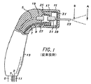
図1を参照すると、多数の異なる種類の先行技術の光学カッターのうちの1つの例は、ファイバーガイド管5と、水ライン7と、空気ライン9と、加圧空気を供給する空気ナイフライン11とを備えている。キャップ15は掌握装置(ハンドヘルド装置)13に嵌合しており、ネジ17によって固着される。ファイバーガイド管5は円筒状の金属片19と内側に当接する。また別な円筒状の金属片21はキャップ15の一部である。レーザーが2個の円筒状の金属物体19と21の間の空隙を繋ぐと、空気ナイフライン11からの加圧空気がレーザーを包囲して冷却する。空気ナイフライン11からの空気は、素子19と素子21の間の界面を冷却した後で、2本の排気部25、27から外に流出する。
Referring to FIG. 1, one example of many different types of prior art optical cutters includes a
レーザーエネルギーはファイバーガイド管23から出て、患者の標的表面に付与される。水ライン7からの水と空気ライン9からの加圧空気は強制的に混合チャンバー29に送られる。空気と水の混合物は混合チャンバー29の内部では非常な擾乱状態にあって、小さな穴31の開いたメッシュスクリーンを通って、このチャンバーから外に出る。空気と水の混合物はファイバーガイド管23の外側に沿って移動してから、管を離れて外科手術領域に接触する。
Laser energy exits the
先行技術の装置と方法の幅広配列の上記以外の実施例に、シュタイナー(Steiner)らに交付された米国特許第5,199,870号(特許文献1)やウオルバーシュト(Wolbarsht)らに交付された米国特許第5,267,856号(特許文献2)などがある。これ以外にも、レーザーエネルギーを利用して柔組織処置を実施するための装置も先行技術に存在しており、この場合、具体的には、レーザーエネルギーにより生体内の柔組織の分離または操作が容易になる。ドレッセル(Dressel)に交付された米国特許第4,985,027号(特許文献3)は、当該技術分野の多種多様な装置の一例を開示している。これによると、先行技術の装置のこの一実施例によると、その内容は引例に挙げることで本明細書の一部をなすものであることは明らかであるが、組織除去装置がNd:YAG由来のレーザーエネルギーを利用して、カニューレ内に保有されている組織を分離する。生体内で組織除去を目的としてNd:YAGレーザーを使用することは、場合によっては非効率になりかねないが、それは、Nd:YAGレーザー由来のエネルギーは水によってそれほど吸収されないからである。更に、Nd:YAGレーザーや、Er:YAGレーザーのような他のレーザーは、構成によっては、唯一の切除メカニズムとして熱暖処置を利用することがある。在る実施例では、隣接組織が炭化し、或いは、熱損傷を被ることもあり、また、場合によっては、熱切除術中に有害で潜在的に有毒な煙が発生することもある。 US Pat. No. 5,199,870 issued to Steiner et al. And U.S. patent issued to Wolbarsht et al. In other embodiments of the wide array of prior art devices and methods. No. 5,267,856 (Patent Document 2). In addition to this, there are devices in the prior art for performing soft tissue treatment using laser energy. In this case, specifically, laser tissue can be used to separate or manipulate soft tissue in vivo. It becomes easy. U.S. Pat. No. 4,985,027 issued to Dressel discloses an example of a wide variety of devices in the art. According to this, according to this embodiment of the prior art device, it is clear that the contents are incorporated herein by reference, but the tissue removal device is derived from Nd: YAG The laser energy in the cannula is used to separate the tissue held in the cannula. The use of an Nd: YAG laser for tissue removal in vivo can be inefficient in some cases because the energy from the Nd: YAG laser is not so much absorbed by water. In addition, other lasers, such as Nd: YAG lasers and Er: YAG lasers, may use thermal warming as the only ablation mechanism in some configurations. In some embodiments, adjacent tissue may be charred or thermally damaged, and in some cases, harmful and potentially toxic smoke may be generated during thermal ablation.
先行技術には、また、内視鏡外科手術処置を実施するための多数の装置が存在しており、例えば、1本以上のカテーテルまたはカニューレを患者の皮膚の小さい孔を通して挿入し、多様な作業通路を設けるが、外科手術中には、これらの作業通路を通して、小型外科手術器具を前進させて患者の体内に入れることができる。特殊な内視鏡応用例としては、関節鏡外科手術、神経内視鏡外科手術、腹腔鏡外科手術、脂肪吸引術などがある。関節鏡外科手術とは、例えば、肩や膝などの関節に関する外科手術のことをいう。先行技術の装置の一実施例は、関節鏡外科手術処置の実施中に使用されてきたが、関節鏡削り装置(シェイバー)である。関節鏡削り装置とは、手術部位内から出る屑や生理食塩水を吸引しながら、同時に組織を切除する回転式の入れ子式管の応用例を意味する。1つのそのような関節鏡システムは、米国マサチューセッツ州アンドーヴァーのスミス・アンド・ネフュー・エンドスコーピー・インコーポレーティッド(Smith & Nephew Endoscopy, Inc)から入手できるディオニクス(DYONICS:登録商標)のモデルEP-1である。 The prior art also has numerous devices for performing endoscopic surgical procedures, such as inserting one or more catheters or cannulas through a small hole in the patient's skin to perform a variety of tasks. Although passages are provided, small surgical instruments can be advanced into the patient's body through these working passages during surgery. Special endoscopic applications include arthroscopic surgery, neuroendoscopic surgery, laparoscopic surgery, liposuction. Arthroscopic surgery refers to surgery related to joints such as shoulders and knees. One example of a prior art device, which has been used during the performance of an arthroscopic surgical procedure, is an arthroscopic device (shaver). The arthroscopic device refers to an application example of a rotary telescoping tube that simultaneously excises tissue while sucking debris and physiological saline from the surgical site. One such arthroscopic system is a DYONICS® model available from Smith & Nephew Endoscopy, Inc., Andover, Massachusetts, USA. EP-1.
上記の器具を用いた切除処置は、モーターを利用して、高速で内側管材を駆動することにより達成される。管状の刃を包囲しているのは外側管状膜であり、その近位端のハブがハンドルと合流するようになっている。上述のもののような高速回転式削り装置を使って関節鏡処置を実施することで、或る場合には、組織に甚大な外傷を生じさせたり、血管裂傷を生じる結果となることがある。 The ablation procedure using the above instrument is achieved by driving the inner tube at high speed using a motor. Surrounding the tubular blade is an outer tubular membrane whose proximal end hub meets the handle. Performing an arthroscopic procedure using a high speed rotary shaving device such as those described above may result in severe trauma to the tissue or vascular laceration in some cases.
本発明は電磁誘導型の切断メカニズムを開示するものであり、この切断メカニズムは硬組織と柔組織とそれ以外の組織材にも高精度の切除術を施すことを可能にする。柔組織には、脂肪、皮膚、粘膜、歯齦、筋肉、心臓、肝臓、腎臓、脳、眼球、血管などがあり、硬組織には、歯のエナメル質、歯の象牙質、歯のセメント質、齲歯、アマルガム、複合素材、歯石、骨、軟骨などがある。 The present invention discloses an electromagnetic induction type cutting mechanism, and this cutting mechanism makes it possible to perform high-precision resection on hard tissue, soft tissue and other tissue materials. Soft tissue includes fat, skin, mucous membranes, toothpick, muscle, heart, liver, kidney, brain, eyeball, blood vessels, etc., and hard tissue includes tooth enamel, tooth dentin, tooth cementum, There are tooth decay, amalgam, composite material, tartar, bone, cartilage.
本発明によれば、電磁誘導型カッターは、カニューレやカテーテルを利用する、内視鏡外科手術処置としても周知である外科手術処置を実施するために使用される。本発明の電磁誘導型カッターの内視鏡外科手術応用例には、関節鏡外科手術、神経内視鏡外科手術、腹腔鏡外科手術、脂肪吸引術、上記以外の内視鏡外科手術処置などがある。電磁誘導型カッターは、具体的には次のような処置で関節鏡外科手術処置を目的として使用されるのに好適である。すなわち、(i)断裂関節間骨、前膝十字靭帯断裂、後膝十字靭帯断裂、膝蓋骨列不正、各種膝滑液障害、膝弛緩体、膝骨欠損、膝骨増殖体異常、膝関節軟骨損傷(膝軟骨軟化症)など、(ii)肩関節滑液障害、肩関節唇側断裂、肩関節弛緩体、肩回旋腱板断裂、肩鎖関節の前衝撃変性性関節疾患、肩関節の関節軟骨疾患、(iii)肘関節滑液障害、肘関節弛緩体、肘関節増殖体異常、肘関節軟骨疾患、(iv)手首関節滑液障害、手首関節弛緩体、手首関節靭帯断裂、手首関節軟骨疾患、(v)腰関節滑液障害、腰関節弛緩体、腰関節唇断裂、腰関節軟骨疾患、(vi)足首関節滑液障害、足首関節弛緩体、足首関節増殖体異常、足首関節骨折、足首関節軟骨疾患など。 In accordance with the present invention, an electromagnetic induction cutter is used to perform a surgical procedure, also known as an endoscopic surgical procedure, utilizing a cannula or catheter. Examples of the endoscopic surgical application of the electromagnetic induction type cutter of the present invention include arthroscopic surgery, neuroendoscopic surgery, laparoscopic surgery, liposuction, and endoscopic surgical procedures other than those described above. is there. Specifically, the electromagnetic induction type cutter is suitable to be used for the purpose of arthroscopic surgical treatment in the following procedure. (I) Ruptured interosseous bone, anterior knee cruciate ligament rupture, posterior knee cruciate ligament rupture, patella row irregularity, various types of knee synovial fluid, knee loose body, knee bone defect, knee proliferative disorder, knee joint cartilage damage (Knee cartilage softening), etc. (ii) shoulder joint synovial disorders, shoulder joint labial rupture, shoulder joint relaxant, shoulder rotator cuff tear, acromioclavicular pre-impact degenerative joint disease, shoulder joint articular cartilage Disease, (iii) elbow joint synovial disorder, elbow joint relaxed body, elbow joint proliferative abnormality, elbow joint cartilage disease, (iv) wrist joint synovial disorder, wrist joint relaxant, wrist joint ligament rupture, wrist joint cartilage disease , (V) hip joint synovial disorder, hip joint relaxed body, hip joint lip tear, hip joint cartilage disease, (vi) ankle joint synovial disorder, ankle joint relaxant, ankle proliferator abnormality, ankle joint fracture, ankle Articular cartilage disease.
本発明の電磁誘導型カッターはカニューレまたはカテーテル内に配備され、その内部の、治療が実施される外科手術部位付近に設置される。本発明の一観点によれば、カニューレまたはカテーテルの直径は最小限にされて、観血を最小限に抑えた処置を実施するためのカニューレまたはカテーテルの全断面積を低減する。本発明のまた別な観点によれば、複数のカテーテルが多様な目的のために一緒に形成される。例えば、関節鏡膝外科手術では、1本のカニューレはカッターを組み入れて吸引除去する構成にし、別個のカニューレは処置中に治療部位を監視する画像化システムを組み入れる構成にすることができる。本発明のまた別な観点によれば、吸引装置、切除装置、画像化装置は全て同一カニューレ内に組み込むことができる。本発明のまた別な観点は、治療部位に空気を供給するために、更に第3のカニューレを備えていてもよい。 The electromagnetic induction cutter of the present invention is deployed within a cannula or catheter and is located within the surgical site where the treatment is performed. In accordance with one aspect of the invention, the diameter of the cannula or catheter is minimized to reduce the overall cross-sectional area of the cannula or catheter for performing a procedure with minimal open blood. According to yet another aspect of the invention, multiple catheters are formed together for a variety of purposes. For example, in arthroscopic knee surgery, one cannula can be configured to incorporate a cutter and be aspirated away, and a separate cannula can be configured to incorporate an imaging system that monitors the treatment site during the procedure. According to another aspect of the present invention, the suction device, the ablation device, and the imaging device can all be integrated into the same cannula. Another aspect of the present invention may further comprise a third cannula for supplying air to the treatment site.
本発明の電磁誘導型カッターは、切断面とは無関係に、極めて精細かつ平滑な切開部を設けることができる。更に、ユーザープログラミング可能な霧化粒子により、多様な切断パラメータのユーザー制御を行える。多様な切断パラメータはまた、噴霧ノズルと電磁エネルギー源のパラメータを変動させることにより、制御することができる。本発明の応用例としては、関節鏡外科手術、神経内視鏡外科手術、腹腔鏡外科手術、脂肪吸引術、歯科手術などの各種医療処置と、それ以外の各種環境とがあり、その場合、熱損傷、制御できない切断パラメータ、および/または、理想的な癒着を得るには不適切な粗表面のうちの1つ以上を減衰させたり排除することにより表面物質を厳密に除去することを目的としている。本発明の或る実施例は、高精度で制御された切断処理を達成するのに水の膜を必要とせず、或いは、特に多孔性の表面を必要としない。或る実施形態では、熱暖処理は切断メカニズムとしては利用されないので、或いは、他の方法を排してまで利用されるという訳ではないので、熱損傷は減衰され、或いは、実質的に排除される。更に、或る実施例では、隣接組織が炭化されたり、熱損傷を被る恐れがなく、或いは、炭化や熱損傷の程度が減じられ、更に、有害で潜在的に有毒な煙も減衰され、或いは、完全に排除される。 The electromagnetic induction type cutter of the present invention can provide an extremely fine and smooth incision portion regardless of the cutting surface. In addition, user-programmable atomized particles allow user control of various cutting parameters. The various cutting parameters can also be controlled by varying the spray nozzle and electromagnetic energy source parameters. Examples of applications of the present invention include various medical procedures such as arthroscopic surgery, neuroendoscopic surgery, laparoscopic surgery, liposuction, dental surgery, and various other environments, To strictly remove surface material by attenuating or eliminating one or more of thermal damage, uncontrollable cutting parameters, and / or rough surfaces that are inappropriate for obtaining ideal adhesion Yes. Certain embodiments of the present invention do not require a water film or a particularly porous surface to achieve a precisely controlled cutting process. In some embodiments, thermal damage is attenuated or substantially eliminated because thermal warming is not used as a cutting mechanism, or is not used to the exclusion of other methods. The Further, in some embodiments, adjacent tissue is not carbonized or subject to thermal damage, or the degree of carbonization or thermal damage is reduced, and harmful and potentially toxic smoke is also attenuated, or , Completely eliminated.
本発明の電磁誘導型カッターは電磁エネルギー源を備えており、これは電磁エネルギーを、標的面に隣接する或る空気容積にまで集束させる。標的面としては、カニューレ内の組織などがある。ユーザー入力装置で実施されるべき切断の種類を特定し、ユーザー入力装置に反応する霧化装置が霧化流体粒子の配合をその空気容積内に投入する。電磁エネルギーはその空気容積にまで集束され、電磁エネルギーの波長は、その空気容積中の霧化流体粒子によって実質的に吸収されるように選択される。電磁エネルギーを吸収すると同時に、霧化流体粒子が膨張し、標的面に切断力を付与する。 The electromagnetic induction cutter of the present invention includes an electromagnetic energy source that focuses the electromagnetic energy to a certain air volume adjacent to the target surface. Target surfaces include tissue within a cannula. An atomizer that identifies the type of cut to be performed at the user input device and is responsive to the user input device throws the blend of atomized fluid particles into the air volume. The electromagnetic energy is focused to the air volume, and the wavelength of the electromagnetic energy is selected to be substantially absorbed by the atomized fluid particles in the air volume. At the same time as the electromagnetic energy is absorbed, the atomized fluid particles expand and impart a cutting force to the target surface.
本発明の電磁誘導型カッターは、上述の関節鏡削り装置などの先行技術の高速回転式シェイバーに勝る改良例を提供することができるが、それは、本発明の電磁誘導型カッターが組織に直接接触することで外傷および血管裂傷を生じる恐れがないからである。その代わりに、切断力は、所要の精度次第で精細侵食プロセスまたは粗侵食プロセスにより、組織の小断片を除去することができる。このプロセスを適用することにより、回転式削り器具に付随する熱、振動、および、圧力を生じることなく、軟骨、線維性軟骨、または、骨を厳密かつ清浄に削り、整形し直し、切り抜き、除去することができる。このシステムは、出血している組織の凝固を行うために、空気および/または水を使わずに利用することができる。電磁誘導型カッターのまた別な応用例によれば、噴霧水は、組織凝集にも寄与し得る凝固防止剤の担体となる。 The electromagnetic induction cutter of the present invention can provide an improvement over prior art high speed rotary shavers, such as the arthroscopic device described above, which is that the electromagnetic induction cutter of the present invention is in direct contact with tissue. This is because there is no fear of causing trauma and vascular tears. Instead, the cutting force can remove small pieces of tissue by a fine or coarse erosion process depending on the required accuracy. By applying this process, the cartilage, fibrous cartilage, or bone is sharply and cleanly cut, reshaped, cut out and removed without the heat, vibration and pressure associated with the rotary sharpener can do. This system can be used without air and / or water to coagulate bleeding tissue. According to another application example of the electromagnetic induction cutter, the spray water becomes a carrier of an anticoagulant that can also contribute to tissue aggregation.
電磁誘導型カッターの上記以外の内視鏡応用例として、神経外科手術応用例と腹部外科手術応用例がある。神経外科手術では、電磁誘導型カッターは脳組織病巣部の除去はもとより、組織の多様な層を切除して病巣部位に達するのに好適である。頭蓋を貫通して骨の内部へ達してから、更に、脳組織を保護している組織の多様な層を通る接近路を設ける方法全体は、本発明の電磁誘導型カッターを用いて達成することができる。
本発明は、本発明の上記以外の特徴および利点と併せて、添付の図面と関連づけて後段の詳細な説明を参照すれば、最もよく理解することができる。
Endoscopic application examples of electromagnetic induction cutters other than the above include neurosurgery application examples and abdominal surgery application examples. In neurosurgery, the electromagnetic induction cutter is suitable not only for removing the brain tissue lesion but also for cutting various layers of tissue to reach the lesion site. The entire method of providing access through various layers of tissue protecting the brain tissue after penetrating the skull and into the interior of the bone is accomplished using the electromagnetic induction cutter of the present invention. Can do.
The invention, together with other features and advantages of the invention, along with the accompanying drawings, is best understood by reference to the following detailed description.
図2は、本発明の実施形態による電磁誘導型カッターを例示したブロック図である。電磁エネルギー源51は制御装置53と搬送システム55の両方に連結される。搬送システム55は標的面57に力を付与する。本発明で具体化されているように、搬送システム55は、レーザー51の経路を設定して、標的面57の上方に配置された干渉区域59内に向ける光ファイバーガイドを備えている。搬送システム55は、ユーザーが特定した霧化流体粒子の配合を干渉区域59内に搬送する霧化装置を更に備えている。制御装置53はレーザー51の多様な動作パラメータを制御し、搬送システム55から出される、ユーザーが特定した霧化流体粒子の配合の特定の特性を更に制御する。
FIG. 2 is a block diagram illustrating an electromagnetic induction type cutter according to an embodiment of the present invention. The
図3は、本発明の電磁誘導型カッターの簡単な実施形態を例示しており、ここでは、光ファイバーガイド61と、空気管63と、水管65とが、掌握式の収納器(ハンドヘルド・ハウジング)67の内部に配置されている。本明細書で使用されているように、「水」という用語は、蒸留水、消イオン水、無菌水、水道水、細菌係数用のコロニー形成単位(CFU)の数を制御した水などのような、多様な液体の変更例を網羅しているつもりである。例えば、飲料水は、わずか500 CFU/mlしか存在しないレベルまで化学処理されることが多く、場合によっては、100 CFU/mlから200 CFU/mlの間ぐらいのこともある。水管65は比較的低圧で作動され、空気管63は比較的高圧で作動される。光ファイバーガイド61からのレーザーエネルギーは、干渉区域59で空気管63からの空気と水管65からの水の上に集束される。本明細書で使用されているように、空気および/または水に言及することで、本発明の多様な修正例を含む意図があるが、例えば、空気および/または水と併用するのであれ、併用しないのであれ、多様な生体適合性の流体を含み、また、そのような流体の均等物、代用物、追加物、置換え物をも含む。例えば、或る修正例では、空気および/または水の代わりに、上記以外の生体適合性流体を使用することができる。空気と水の混合物中の霧化流体粒子は、光ファイバー管61のレーザーエネルギー由来のエネルギーを吸収して、爆発する。このような霧化流体粒子由来の爆発力は標的面57に切断力を付与する。
FIG. 3 illustrates a simple embodiment of the electromagnetic induction type cutter according to the present invention, in which an
図1を再度参照すると、先行技術の光学カッターは、レーザーエネルギーを或る面積、例えば、面積Aの標的面上に集束させるが、本発明の電磁誘導型カッターは、或る実施形態では、干渉区域、例えば、区域Bにレーザーエネルギーを集束させるような構成にすることができる。先行技術の光学カッターは、組織を切断することを直接の目的としてレーザーエネルギーを使用し、或る構成の本発明の電磁誘導型カッターは、霧化流体粒子を膨張させて標的面上または標的面の内部に少なくとも部分的な切断力を付与する目的で、レーザーエネルギーを使う。このような、先行技術の光学カッターの具体例は、興味の対象である領域を切除するのに大量のレーザーエネルギーを使い、また、興味の対象である領域を冷却する目的と、切断組織を除去する目的の両方で、大量の水を使う。 Referring back to FIG. 1, the prior art optical cutter focuses the laser energy onto a target surface of a certain area, eg, area A, while the electromagnetic induction cutter of the present invention is an interference in some embodiments. It can be configured to focus the laser energy on an area, eg, area B. Prior art optical cutters use laser energy for the direct purpose of cutting tissue, and in one configuration, the electromagnetic induction cutter of the present invention expands atomized fluid particles on the target surface or target surface. Laser energy is used to give at least a partial cutting force inside. Such a prior art optical cutter embodiment uses a large amount of laser energy to ablate the area of interest and also aims to cool the area of interest and remove the cut tissue. Use large amounts of water for both purposes.
これに比べて、本発明の電磁誘導型カッターは、或る実施形態では、比較的少量の水を使い、また更に、水から生成された霧化流体粒子を膨張させる目的で、少量のレーザーエネルギーしか使用しない構成になっている。本発明の電磁誘導型カッターによれば、外科手術領域を冷却するのに水は必要とされない場合もあり、というのは、破裂した霧化流体粒子は、標的面に接触する前に、発熱反応により冷却される。従って、本発明の或る実施形態の霧化流体粒子は、標的面に接触する前に、加熱され、膨張され、冷却される。従って、本発明の或る実施形態の電磁誘導型カッターは、炭化や退色を生じることなく、切断を行える。 In contrast, the electromagnetic induction cutter of the present invention, in certain embodiments, uses a relatively small amount of water and, further, a small amount of laser energy for the purpose of expanding atomized fluid particles generated from the water. It is configured to use only. In accordance with the electromagnetic induction cutter of the present invention, water may not be required to cool the surgical area, since the ruptured atomized fluid particles are exothermic before contacting the target surface. It is cooled by. Thus, the atomized fluid particles of certain embodiments of the present invention are heated, expanded and cooled before contacting the target surface. Therefore, the electromagnetic induction type cutter of an embodiment of the present invention can perform cutting without causing carbonization or fading.
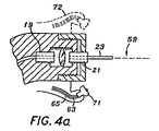
図4aは電磁誘導型カッターの実施形態を例示している。霧化流体粒子を生成するための霧化装置にはノズル71が設けられており、該ノズルは、所望の切断のタイプに従って、霧化流体粒子を多様に空間分布させるための、他のノズル(図示せず)と交換することもできる。仮想線で示された第2のノズル72も使用することができる。電磁誘導型カッターの切断力は、使用者の抑制により、更に制御される(図4b)。簡単な実施形態では、ユーザー制御部75は、ノズル71に入る空気と水の圧力を制御する。従って、ノズル71は、ユーザーが指定した、霧化流体粒子と噴霧スプレイ多数の異なる配合を生じることができる。
FIG. 4a illustrates an embodiment of an electromagnetic induction cutter. The atomizing device for generating atomized fluid particles is provided with a
強いエネルギーが光ファイバーガイド23から放射される。この強いエネルギーは、レーザーなどのコヒーレント源から生成される。例示の実施形態では、レーザーは、波長が2.70ミクロンから2.80ミクロンの範囲の電磁エネルギーを生成するエルビウム、クロミウム、イットリウム、スカンジウム、ガリリウム、ガーネット(Er,Cr:YSGG)固相レーザーか、または、波長が2.94ミクロンの電磁エネルギーを生成するエルビウム、イットリウム、アルミニウム、ガーネット(Er:YAG)固相レーザーの、いずれかである。Er,Cr:YSGG固相レーザーは波長を約2.78ミクロンにすることができ、Er:YAG固相レーザーは波長を約2.94ミクロンにすることができる。
Strong energy is emitted from the
例示の実施形態では水が含まれているが、ノズル71から放射される流体は、流体がよく吸収することができるように選択されている電磁エネルギー源の適切な波長の、別な流体を含んでいてもよい。それ以外の可能なレーザーシステムとしては、波長が2.70ミクロンから2.80ミクロンの範囲の電磁エネルギーを生成するエルビウム、イットリウム、スカンジウム、ガリリウム、ガーネット(Er:YSGG)固相レーザー、波長が2.94ミクロンの電磁エネルギーを生成するエルビウム、イットリウム、アルミニウム、ガーネット(Er:YAG)固相レーザー、波長が2.69ミクロンの電磁エネルギーを生成するクロミウム、ツリウム、エルビウム、イットリウム、アルミニウム、ガーネット(CTR:YAG)固相レーザー、波長が2.71ミクロンから2.86ミクロンの電磁エネルギーを生成するエルビウム、イットリウム、オルトアルミネート(Er:YALO3)、波長が2.10ミクロンの電磁エネルギーを生成するホルミウム、イットリウム、アルミニウム、ガーネット(Ho:YAG)固相レーザー、波長が266ナノメートルの電磁エネルギーを生成する4倍量ネオジミウム、イットリウム、アルミニウム、ガーネット(4倍量Nd:YAG)固相レーザー、波長が193ナノメートルの電磁エネルギーを生成するフッ化アルゴン(ArF)エキシマーレーザー、波長が308ナノメートルの電磁エネルギーを生成する塩化キセノン(XeCl)エキシマーレーザー、波長が248ナノメートルの電磁エネルギーを生成するフッ化クリプトン(KrF)エキシマーレーザー、波長が9.0ミクロンから10.6ミクロンの電磁エネルギーを生成する二酸化炭素(CO2)などがある。水は、生体適合性があること、ふんだんに在ること、低価格であることなどの理由により、好ましい流体として選択することができる。使用される実際の流体は、選択された電磁エネルギー源(すなわち、レーザー)の波長に適合する(つまり、よく吸収される)。
Although the illustrated embodiment includes water, the fluid emitted from the
電磁エネルギー源は、1 Hzを越える反復率、1ピコ秒から1000マイクロ秒の間の範囲のパルス持続時間、1パルスあたり1ミリジュールを越えるエネルギーで構成することができる。本発明の1つの動作モードによると、この電磁エネルギー源は、波長が約2.78ミクロン、反復率は20 Hz、パルス持続時間は140マイクロ秒、エネルギーは1パルスあたり1ミリジュールから300ミリジュールの間である。 The electromagnetic energy source can be configured with a repetition rate in excess of 1 Hz, a pulse duration in the range between 1 picosecond and 1000 microseconds, and an energy in excess of 1 millijoule per pulse. According to one mode of operation of the present invention, this electromagnetic energy source has a wavelength of about 2.78 microns, a repetition rate of 20 Hz, a pulse duration of 140 microseconds, and an energy between 1 and 300 millijoules per pulse. It is.
一実施形態では、電磁エネルギー源はパルス持続時間が数ナノ秒ほどであり、これは、電磁エネルギー源をQスイッチ処理することにより得られるが、また別な実施形態では電磁エネルギー源はパルス持続時間が数ピコ秒ほどであり、これは、電磁エネルギー源をモードロックすることで得られる。Qスイッチ処理は、高いパルス出力を生成するために広く採用されている、レーザー動作の従来からの様式である。ウオルター・コエヒナー(Walter Koechner)著、1996年刊行の書籍、「固相レーザー工学(Solid-State Laser Engineering)」(大幅に改定した最新の第4版)(非特許文献1)は、Qスイッチ式レーザー理論と多様なQスイッチ装置を開示しており、この書籍の内容全体は、ここに援用することにより本明細書の一部をなすものであることは明らかである。Qスイッチ装置は、一般に、ポンプサイクル中にレーザー動作を抑止するものであり、その手段としては、光経路を遮断してミラー不整列を発生させるか、または、共鳴装置ミラーのうちの1個の反射率を低下させるか、いずれかである。フラッシュランプパルスの終わり付近で、最大エネルギーがレーザーロッドに保存されてしまうと、高度なQ条件が確率され、レーザーから巨大パルスが発射される。結晶または液体の電気光学効果を利用することにより、非常に高速の電子制御式の光遮断装置を作ることができる。音響光学Qスイッチは、透明な光素材の塊、通常は溶融シリカの塊の内部に超音波を発射する。上述の書籍「固相レーザー光学」(大幅に改定した最新の第4版)の第8章は、上述のQスイッチ装置とその他の多様なQスイッチ装置を開示している。モードロックは従来からの処置手順であって、レーザーの長軸線方向の様式をフェーズロックし、また、レーザー放射の帯域とは逆の関係にあるパルスを利用する。モードロックは上述の書籍「固相レーザー光学」(大幅に改定した最新の第4版)の500頁から561頁に記載されている。 In one embodiment, the electromagnetic energy source has a pulse duration on the order of a few nanoseconds, which is obtained by Q-switching the electromagnetic energy source, but in another embodiment the electromagnetic energy source has a pulse duration. Is about a few picoseconds, which can be obtained by mode-locking the electromagnetic energy source. Q-switching is a traditional mode of laser operation that has been widely adopted to produce high pulse power. A book published in 1996 by Walter Koechner, “Solid-State Laser Engineering” (the latest fourth edition, which has been significantly revised) (Non-Patent Document 1) is a Q-switch type. It is clear that laser theory and various Q-switch devices are disclosed, and the entire contents of this book are incorporated herein by reference. A Q-switch device generally suppresses laser operation during the pump cycle by blocking the optical path to cause mirror misalignment or one of the resonator mirrors. Either reflectivity is lowered. Near the end of the flashlamp pulse, if the maximum energy is stored in the laser rod, an advanced Q condition is established and a huge pulse is emitted from the laser. By utilizing the electro-optic effect of crystal or liquid, a very high speed electronically controlled light blocking device can be made. The acousto-optic Q switch emits ultrasonic waves inside a transparent light mass, usually a fused silica mass. Chapter 8 of the above-mentioned book "Solid-Phase Laser Optics" (latest revised 4th edition) discloses the above-described Q-switch device and various other Q-switch devices. Mode-locking is a traditional treatment procedure that utilizes a pulse that is phase-locked to the long axis direction of the laser and is inversely related to the band of laser radiation. Mode-locking is described on pages 500 to 561 of the above-mentioned book "Solid-Phase Laser Optics" (latest revised 4th edition).
霧化流体粒子は、或る実施形態では、干渉区域内で電磁エネルギーを吸収すると、切断力の少なくとも一部を供与する。他の実施形態では、切断力の一部または全部が、熱効果のような他の効果またはメカニズムに由来する。しかし、霧化流体粒子は、電磁エネルギーが出力される源である光ファイバーガイドを洗浄または冷却するという、第2の機能を提供することがある。電磁エネルギーを搬送するための搬送システム55(図2)としては、光ファイバーエネルギーガイドまたはその均等物を挙げることができるが、これはレーザーシステムに取り付けて、所望の作業部位まで移動するものである。光ファイバーまたは導波路は、通例は、長く、薄く、軽量であり、また、操作も容易である。光ファイバーはフッ化カルシウム(CaF)、酸化カルシウム(CaO2)、酸化ジルコニウム(ZrO2)、フッ化ジルコニウム(ZrF)、サファイア、中空導波路、液状コア、TeXガラス、石英シリカ、硫化ゲルマニウム、硫化砒素、酸化ゲルマニウム(GeO2)、その他の材料から作ることができる。上記いがいの搬送システムとしては、ミラー、レンズ、それ以外の光学素子などの装置があり、この場合、エネルギーは空洞を通って移動し、多様なミラーによって方向を設定され、特殊レンズを用いて標的の切断部位へ集束される。本発明の医療応用例の光搬送装の実施形態は光ファイバー導体を介在手段とするが、これは、軽量、廉価、医者、歯科医、医療従事者にとって使い慣れた寸法と重量のハンドピースの内部に実装することができるからである。 The atomized fluid particles, in certain embodiments, provide at least a portion of the cutting force upon absorbing electromagnetic energy within the interference zone. In other embodiments, some or all of the cutting force is derived from other effects or mechanisms such as thermal effects. However, the atomized fluid particles may provide a second function of cleaning or cooling the fiber optic guide from which electromagnetic energy is output. The transport system 55 (FIG. 2) for transporting electromagnetic energy can include a fiber optic energy guide or equivalent, which is attached to the laser system and moved to the desired work site. Optical fibers or waveguides are typically long, thin, lightweight, and easy to operate. Optical fiber is calcium fluoride (CaF), calcium oxide (CaO 2 ), zirconium oxide (ZrO 2 ), zirconium fluoride (ZrF), sapphire, hollow waveguide, liquid core, TeX glass, quartz silica, germanium sulfide, arsenic sulfide , Germanium oxide (GeO 2 ) and other materials. The irrigation transport system includes devices such as mirrors, lenses, and other optical elements. In this case, energy travels through the cavity and is directed by various mirrors, using special lenses. Focused to the target cutting site. The embodiment of the light transport device of the medical application of the present invention uses an optical fiber conductor as an intervening means, which is light weight, inexpensive, inside a handpiece of a size and weight familiar to doctors, dentists, and medical workers. This is because it can be implemented.
ノズル71は、選択された流体の小粒子の工学的に処理された配合を作るために利用される。ノズル71は、液体のみ、空気送風、空気利用、渦巻き型、中実円錐型などの、幾つか異なる意匠のものを含む。流体は、所与の圧力と速度でノズル71を出ると、ユーザーが制御できる寸法、速度、空間分布の粒子に変形させられる。ノズルは、設計パラメータに従って、球形、楕円形、または、それ以外の形状で多様な異なる寸法の開口部を備えている。
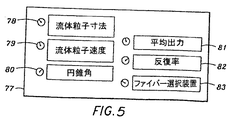
図5は霧化流体粒子のユーザープログラミング可能性を実現するための制御パネル77を例示している。例えば、流体の厚量と流速を変動させることにより、ユーザーは複数の霧化流体粒子特性を制御することができる。このような特性がレーザーエネルギーの吸収効率と、それに続く電磁誘導型カッターの切断効果を決めることがある。このような制御パネルは、例えば、流体粒子寸法制御部78、流体粒子速度制御部79、円錐角制御部80、平均出力制御部81、反復率82、ファイバー選択部83などから構成される。
FIG. 5 illustrates a
円錐角は、例えば、ノズル71の物理的構造を変えることにより、制御される。多様なノズル71は電磁誘導型カッターに交換自在に設置される。これに代わる例として、1個のノズル71の物理構造を変化させてもよい。
The cone angle is controlled, for example, by changing the physical structure of the
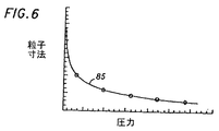
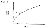
図6は平均流体粒子寸法に対する圧力のグラフ表示85を例示している。同グラフによると、ノズル71内の圧力が上昇すると、霧化流体粒子の平均流体粒子寸法は小さくなる。図7のグラフ87は、圧力上昇に伴って霧化流体粒子の平均流体粒子速度が上昇するのを示している。
FIG. 6 illustrates a
本発明の一実施形態によると、場合によっては純粋に熱切断力を含むこともある、従来の切断力を利用する代わりに、少なくとも部分的には破壊的切断力(機械力)によって、標的面から物質が除去される。レーザーエネルギーの使用を、標的物質上への力の誘導のみに限定することもできる。従って、霧化流体粒子は、レーザーの電磁エネルギーを、本発明の前述の実施形態の切断効果を達成するのに必要なエネルギーへと変換するための媒体として作用する。このような実施形態のレーザーエネルギー自体は、標的物質によって直接吸収されることはない。本発明の相互作用は、或る場合には、より安全、より迅速で、かつ/または、或る従来のレーザー切断システムに付随するのが通例であった、有難くない熱の副次効果を排除することができる。 According to one embodiment of the present invention, instead of utilizing a conventional cutting force, which may include purely a thermal cutting force in some cases, at least in part by a destructive cutting force (mechanical force) The material is removed from. The use of laser energy can also be limited to the induction of force on the target material. Thus, the atomized fluid particles act as a medium for converting the electromagnetic energy of the laser into the energy necessary to achieve the cutting effect of the previous embodiments of the present invention. The laser energy itself in such an embodiment is not directly absorbed by the target material. The interaction of the present invention, in some cases, is safer, faster, and / or eliminates the beneficial thermal side effects that are commonly associated with certain conventional laser cutting systems. can do.
光ファイバーガイド23(図4a)は、標的面の極めて近位に設置される。しかし、光ファイバーガイド23は、実際には、標的面に接触することはない。ノズル71からの霧化流体粒子は干渉区域59に投与されるので、光ファイバーガイド23の目的も同様に、レーザーエネルギーをこの干渉区域に投与することである。本発明の一特性は、真っ直ぐなサファイアまたは曲がったサファイアの光ファイバーガイド23を形成することである。しかし、光ファイバーガイド23の組成とは無関係に、本発明の別な特性は、光ファイバーガイド23にノズル71からの空気および水の洗浄効果を及ぼすことである。
The fiber optic guide 23 (FIG. 4a) is placed very proximal to the target surface. However, the
ノズル71が標的面に幾分か直接的に向けられると、この洗浄効果が最適になることが本件発明者らには分かっている。例えば、切断処理から生じる屑は、ノズル71からの噴射によって除去される。
The inventors have found that this cleaning effect is optimal when the
更に、本件発明者らは、標的面に向けた場合のノズルの配向は、本発明の切断効率を高める。霧化流体粒子は各々が標的面に向かう少量の初期運動エネルギーを保有している。光ファイバーガイド23からの電磁エネルギーが霧化流体粒子に接触すると、流体粒子の外面が集束レンズとして働き、水粒子の内部へエネルギーを集束させる。図8に例示されているように、水粒子101には照射面103、蔭になった面105、粒子速度107が存在する。集束された電磁エネルギーは水粒子101によって吸収され、水粒子の内部を急速に加熱して破裂させる。この発熱爆破により、破裂した水粒子101の残余の部分が低温化される。周囲の霧化流体粒子が、破裂した水粒子101の各部の低温化を更に促進する。この爆破によって、圧力波が発生する。この圧力波と、破裂した水粒子101の上昇した運動エネルギーのうちの幾らかが標的面107に向けて当てられる。最初に破裂した水粒子101に由来する入射エネルギー部分は、高速かつ高い運動エネルギーで移動することはないが、或る実施形態では、これが圧力波と一緒に、標的面107に強い集中した力を付与する。
Furthermore, the inventors of the present invention enhance the cutting efficiency of the present invention by the orientation of the nozzle when facing the target surface. The atomized fluid particles have a small amount of initial kinetic energy, each toward the target surface. When electromagnetic energy from the
このような力により、標的面107は「削り取り」作用により、物質表面から分断される。標的面107は気化作用、分離化作用、または、炭化作用の程度が低減されないこともあり、低減されることもある。本発明によって、削り取りプロセスは、所望量の物質が標的面107から除去されてしまうまで反復される。
By such a force, the
ノズル71は、ほぼ平均値程度で狭い分布の流体粒子寸法範囲で霧化噴射を生じるような構成にされる。切断効率を制御するためのユーザー入力装置は、簡単な圧力・流速ゲージ75を備えていてもよく(図4b)、或いは、例えば、図5に例示されているような制御パネルを備えていてもよい。高分解能切断を目的としたユーザー入力の場合には、比較的小型の流体粒子がノズル71によって生成される。低分解能切断を指定したユーザー入力に対しては、比較的大型の流体粒子が生成される。深い透過切断を指定したユーザー入力により、ノズル71は比較的低密度部分の流体粒子を生成し、また、浅い透過切断を指定したユーザー入力により、ノズル71は比較的高密分布の流体粒子を生成する。ユーザー入力装置が図4bの簡単な圧力・流速ゲージ75を備えている場合は、高切断効率を指定したユーザー入力に応じて、比較的低密度分布の比較的小型の流体粒子を生成することができる。同様に、低切断効率を指定したユーザー入力に応じては、比較的高密度の比較的大型流体粒子を生成することができる。
The
柔組織には、脂肪、皮膚、粘膜、歯齦、筋肉、心臓、肝臓、腎臓、脳、眼球、血管などがあり、硬組織には、歯のエナメル質、歯の象牙質、歯のセメント質、齲歯、アマルガム、複合素材、歯石、骨、軟骨などがある。「脂肪」という語は、脂または油を含むもので膨張した細胞からなる動物組織のことをいう。胸部組織のような他の柔組織は、人体組織や他の動物組織を含む。これ以外の物質には、ガラスや半導体チップ面などがある。電磁誘導型切断メカニズムを使って、生物物質、セラミックス、セメント、重合体、陶器、移植可能素材と、金属素子、セラミック素子、重合体素子などの素子を切断または融除することもできる。電磁誘導型切断メカニズムを使って、金属面、プラスチック面、重合体面、ラバー面、ガラス面、結晶物質面、コンクリート面、木、布、紙、植物、それら以外の人造物と自然発生物を切断または融除することもできる。生物素材には、歯垢、歯石、有機的一貫性のある生体層または生体膜、スミア層、多糖層、歯苔層などがある。スミア層は断片的な生体物質であり、タンパク質などがあるが、生きているものと死んだもののいずれか、または、その両方の組み合わせを含むこともある。多糖層は、食べ物の残り滓や唾液のコロイド懸濁を含むことが多い。歯垢は、食べ物や唾液を含む膜のことを言い、その中には細菌が混じっていたり、細菌が住んでいたりすることが多い。これらの層または膜は歯やそれ以外の生体面、非生体面に堆積される。金属としては、具体的には、アルミニウム、銅、鉄などがある。 Soft tissue includes fat, skin, mucous membranes, toothpick, muscle, heart, liver, kidney, brain, eyeball, blood vessels, etc., and hard tissue includes tooth enamel, tooth dentin, tooth cementum, There are tooth decay, amalgam, composite material, tartar, bone, cartilage. The term “fat” refers to animal tissue consisting of cells that are swollen with fat or oil. Other soft tissues, such as breast tissue, include human tissue and other animal tissues. Other materials include glass and semiconductor chip surfaces. Electromagnetic induction type cutting mechanisms can also be used to cut or ablate biological materials, ceramics, cements, polymers, pottery, implantable materials and elements such as metal elements, ceramic elements, polymer elements. Cutting metal, plastic, polymer, rubber, glass, crystalline, concrete, wood, cloth, paper, plants, and other artifacts and natural products using an electromagnetic induction cutting mechanism Or it can be ablated. Biological materials include plaque, calculus, organically consistent biological layers or membranes, smear layers, polysaccharide layers, and dental plaque layers. The smear layer is a piece of biological material, such as protein, but may include either live or dead, or a combination of both. The polysaccharide layer often contains a food residue or a colloidal suspension of saliva. Plaque is a film that contains food and saliva, and it is often mixed with bacteria or living with bacteria. These layers or films are deposited on teeth, other biological surfaces, and non-biological surfaces. Specific examples of the metal include aluminum, copper, and iron.
ユーザーは、ノズル71から外に出た霧化流体粒子の配合を調節して、光ファイバーゲージ23(図4a)の冷却および洗浄を効率よく実施することもできる。本発明の実施形態によれば、霧化流体粒子の配合は、光ファイバーガイド23を効果的に冷却するための分布、速度、平均直径を備えており、同時に、外科手術部位によって導入することができる粒状屑から光ファイバーガイド23を清浄に保つことができる。
The user can also efficiently cool and clean the optical fiber gauge 23 (FIG. 4 a) by adjusting the composition of the atomized fluid particles that have exited from the
再度、図8を参照すると、電磁エネルギーは照射面103の霧化流体粒子101に接触し、霧化流体粒子の或る深度まで透過する。集束された電磁エネルギーは流体によって吸収され、霧化流体粒子101の爆発性気化を誘発する。
Referring again to FIG. 8, electromagnetic energy contacts the atomized
霧化流体粒子の直径は、入射電磁エネルギーの波長よりも短いか、それにほぼ等しいか、または、それよりも長い。このような3つの場合の各々について、電磁エネルギーと霧化流体粒子との間に異なる相互作用が生じる。霧化流体粒子の直径が電磁エネルギーの波長よりも短い場合(d<λ)、流体粒子101の内側の流体の全体積分がレーザーエネルギーを吸収し、爆発性気化を誘発する。流体粒子101は破裂し、その内容物を放射状に放出する。このような相互作用の結果として、この爆発に由来する放射方向の圧力波が生み出され、伝播方向に投射される。水粒子101の破裂の結果として生じる部分と、圧力波は、或る実施形態では、少なくとも一部が、標的面107から物質を切断して除去する「削り取り」効果を生じるように作用する。流体粒子101の直径が、電磁エネルギーの波長に概ね等しい場合(d≒λ)である場合、レーザーエネルギーは、流体粒子101内の流体によって吸収されてしまう前に、流体粒子101を透過して移動する。ひとたび吸収されてしまうと、流体粒子の遠位側(レーザーエネルギー放出面)は温度上昇し、爆発性気化が生じる。この場合、粒子内部の流体は流体粒子の遠位側を破って激しく放出され、標的面に向かって爆発性圧力波とともに迅速に移動する。レーザーエネルギーは流体粒子101を透過することができるし、粒子直径の寸法に近い深さまで吸収される。流体粒子の直径が電磁エネルギーの波長よりも長い場合(d>λ)、レーザーエネルギーは照射面103を通って短い距離だけ流体粒子101を透過し、照射面103を気化させる。照射面103の気化は、流体粒子101の残余の部分を推進させて標的物質面107に向かわせる傾向を有している。従って、初期流体粒子101の質量の一部が運動エネルギーに変換された結果、流体粒子101の残余の部分を推進して、高い運動エネルギーで標的表面に向かう。このような高い運動エネルギーは、流体粒子101の初期運動エネルギーに添加されるエネルギーである。このような効果は、後端部が噴霧状のマイクロ水ロケットとして視認することができるが、これにより、高速で粒子を標的面107に向けて推進させるのに役立つ。本発明の電磁誘導型カッターは、高分解能切断をもたらすことができる。先行技術の或る装置の切断とは異なり、本発明の切断は清浄かつ厳密である。他の利点の中でもとりわけ、この切断により理想的な接着面が供与され、切断部の周囲の残留物質に応力を与えることがない。
The diameter of the atomized fluid particles is shorter than, approximately equal to, or longer than the wavelength of the incident electromagnetic energy. For each of these three cases, a different interaction occurs between the electromagnetic energy and the atomized fluid particles. When the diameter of the atomized fluid particles is shorter than the wavelength of the electromagnetic energy (d <λ), the total integral of the fluid inside the
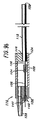
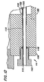
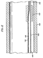
図9および図14は、本発明による電磁誘導型カッターを利用する組織除去装置110の実施形態を例示している。組織除去装置110は吸引カニューレ112を有しており、該カニューレの遠位端114には柔組織吸引入口ポート120が設けられており、また、装置は図9aおよび図10aに例示されているような形状のカニューレ先端部118を更に有している。図9aおよび図10aに例示されているように、カニューレ先端部118は、溶着または溶接によりカニューレ112に取り付けられた、略円状先端部、鈍先端部、または、弾丸状先端部であるのが有利である。図9aおよび図10bでは、組織除去装置110は開放カニューレ形状を有するような構成になっている。図9に例示されているように、カニューレ近位端116は遠位ハンドル端キャップ124の内部に保有され、吸引柔組織出口ポート128は近位ハンドル端キャップ126の内部に保有され、遠位ハンドル端キャップ124と近位ハンドル端キャップ126はハンドル122の内部に保有される。柔組織出口ポート128は、可塑性管材(図示せず)によって吸引源に接続されている。
9 and 14 illustrate an embodiment of a
図9から図13に例示されているように、流体・レーザーファイバーガイド管は、組織除去装置110の内部を、レーザー・流体源ポート141の位置に在る近位端ハンドル端キャップ126から延びて、図10aに例示されている実施形態では、柔組織吸引入口ポート120より直ぐ近位の点140(図10)で終端している。図10bでは、レーザー・流体源ポート161は、干渉区域159に隣接している点140で終端している。流体・レーザーファイバーガイド管136は、その一部が、近位ハンドル端キャップ126に穿孔加工された同軸の流体チャネル130(図12)の内側に載置されており、大型の流体・レーザーファイバーガイド管132、ガイド管遷移カプラー134、および、小型流体・レーザーファイバーガイド管136を備えている。ガイド管遷移カプラー134は、カニューレ116の近位端より近位のハンドル122の内側に設置され、穿孔加工により大型ガイド管132と小型ガイド管136の外径を収容するようになっている。溶接や溶着などの手段を利用して、ガイド管構成部材は一緒に接合されているとともに、近位ハンドル端キャップ126にも接合され、吸引カニューレの内壁の内側に置かれる。流体−レーザーファイバーガイド管は、その保持部にOリングシール146(図12)が設けられており、その位置はレーザーエネルギー源ポート141の位置にある近位ハンドル端キャップ126の内側である。任意のガイド管遷移カプラー134を使って、比較的径が小さい小型の流体・レーザーファイバーガイド管136を設けるようにしてもよい。任意のガイド管遷移カプラー134は、吸引カニューレ112の内側により大きな空間を設けることもできる。
As illustrated in FIGS. 9-13, the fluid / laser fiber guide tube extends from the proximal end handle
レーザー光ファイバ搬送システムが流体・レーザーファイバーガイド管の内部に収納されている。図11に例示されているように、レーザー光ファイバー搬送システムは光ファイバーガイド123、空気管163、および、水管165を備えている。光ファイバーガイド123、空気管163、水管165は、図4aを参照しながら先に説明した光ファイバーガイド23、空気管63、および、水管65に類似している。水管165は生理食塩水源およびポンプに接続されており、空気管は加圧空気源に接続されている。空気管163と水管165はノズル171で終端しているが、このノズルは図4aを参照しながら先に説明したノズル171に類似している。或る実施形態では、光ファイバーガイド123、空気管163、および、水管165は一緒に作動して、電磁誘導による切断力を発生する。また別な実施形態では、ノズル171に接続されているのは水管165だけで、空気管は存在しない。この場合、ノズル171は水専用型のノズルである。上述構成のいずれを実施しても、修正された実施形態で、上述のような力を発生させることができる。
The laser fiber optic transport system is housed inside the fluid / laser fiber guide tube. As illustrated in FIG. 11, the laser optical fiber transport system includes an
水管から発射された流体が水を基本とし、かつ、光ファイバーガイド123からの電磁エネルギーが水に大いに吸収されるような実施形態では、事例によっては、光ファイバーガイド123の出力端と標的面との間が、比較的無水性の環境(体液が最小限に抑えられている環境)であるのが望ましいこともある。或る実施形態では、流体粒子を霧化分布を生じるために、ノズル171と干渉区域159(図11を参照のこと)との間を無水性の環境に保つことも望ましい場合がある。本発明の一観点は、ノズル171から体液を完全排出した状態を保つことを含み、干渉区域159が性能を向上させる。従って、出血を低減する手段が実施例によっては望ましいことがある。これに関連して、カニューレ118の遠位刃は高周波(RF)切断用ワイヤを備えている。RF切断用ワイヤを利用する電子外科手術処置は、柔組織切除および多様な形式の凝固を実施するための高周波(RF)エネルギーを実現する。
In embodiments where the fluid launched from the water tube is water-based and electromagnetic energy from the
電気外科手術では、活性電気外科手術電極によって付与される高密度のRF電流は、電極の表面が小さければ(ワイヤ式、ニードル式、槍状刀式、解剖用小刀式など)、切断作用を生じる。更に、切断性能上、電流波形が重要な要因となる。解剖用小刀式の切除には平滑な不変調電流が一層適切であるが、変調電流は切断に伴って、所定の凝固を可能にする。選択された出力強度ばかりか、エネルギー発生器の出力インピーダンスも、切断性能については重要となる。電気外科手術切除用電極は、精鋭な微細ニードル式、槍状刃式、ナイフ式、ワイヤ式またはバンドループ式、係蹄式、電力付勢解剖用小刀、電力付勢解剖用鋏などの場合がある。(1)電極の形状、(2)周波数変調および波形変調、(3)ピークピーク電圧、および、(4)エネルギー発生器の電流と出力インピーダンス次第で、アーク放電を全く生じずに切断部は平滑となったり、アーク放電のために組織に炭化や火傷を生じる恐れがあったりする。電気外科凝固を実施するためには、例えば、噴霧凝固モードで軽度の炭化や焼灼を実施する方法を採用する。多様な凝固プロセス中の温度差は、摂氏100度から摂氏500度までの間の温度を優に越えることがある。上述の手段は所望される切除量、および/または、所望される凝固量に応じて選択されるべきであるが、これは、切除される組織の種類といったような多様なパラメータを含む機能である。発煙を低減するという本発明の目的に従って、バイポーラ型の応用例や不変調電流を利用した切除を実施するようにしてもよい。 In electrosurgery, the high-density RF current imparted by the active electrosurgical electrode produces a cutting action if the electrode surface is small (wire, needle, scissors, dissecting knife, etc.) . Furthermore, the current waveform is an important factor in cutting performance. A smooth unmodulated current is more appropriate for dissecting scalpel resections, but the modulated current allows for a predetermined coagulation upon cutting. The output impedance of the energy generator as well as the selected output intensity is important for cutting performance. Electrosurgical resection electrodes may be fine microneedles, scissors blades, knives, wires or band loops, snares, power-powered dissecting knives, power-powered dissecting scissors, etc. is there. Depending on (1) electrode shape, (2) frequency and waveform modulation, (3) peak-peak voltage, and (4) current and output impedance of the energy generator, no arc discharge occurs and the cut is smooth Or arcing may cause carbonization or burns in the tissue. In order to perform electrosurgical coagulation, for example, a method of performing mild carbonization or cauterization in a spray coagulation mode is employed. Temperature differences during various solidification processes can well exceed temperatures between 100 degrees Celsius and 500 degrees Celsius. The above means should be selected depending on the desired amount of resection and / or desired amount of coagulation, but this is a function that includes various parameters such as the type of tissue to be resected. . In accordance with the object of the present invention to reduce fuming, bipolar applications and ablation utilizing unmodulated current may be performed.
加圧空気、加圧窒素、または、加圧酸素などを切除中または切除と切除の合間のいずれかに多様な流量と多様な間隔で空気管163から出力することで、電磁誘導による切断力を得るように比較的無水性の作業環境を設けるように図ることができる。例えば、切断して除去されるべき標的組織の付近に空気空洞を設けるための通気処置を利用して、干渉区域159に望ましくない体液が導入されるのを減衰するようにしてもよい。
By outputting compressed air, pressurized nitrogen, pressurized oxygen, etc. from the
可撓性の吸引管材が生成して伝達する負圧の働きにより、干渉区域159から体液と切除組織とノズル171からの空気および水とが排出される。目下具体例として説明されているように、大型の流体・レーザーファイバーガイド管132は空気源に接続されており、可撓性の吸引管材によって生成および伝達された負圧の働きで、大型の流体・レーザーファイバーガイド管132と小型の流体・レーザーファイバーガイド管136を通して空気を吸入する。大型の流体・レーザーファイバーガイド管132に連結された空気源は湿った空気を含んでいてもよい。小型の流体・レーザーファイバーガイド管136から外に向かう空気流の働きで、ノズル171、光ファイバーガイド123の出力端140、および、干渉区域159を体液が比較的無い状態に維持する。体液を更に除去するのが望ましい場合は、1本以上の加圧空気用ラインでカニューレ先端部118に隣接するカニューレ112の遠位端114に至る経路を設けることができる。1本または複数本の加圧空気用ラインを活動状態にし、カニューレの遠位端でカニューレの管腔に空気を導入することで、管腔からの体液と水の除去を促進することができる。吸引入口ポート内の脂肪組織がカニューレの管腔内に封鎖部を形成したために、負圧によってカニューレ管腔の外に体液を引き出せる場合には、干渉区域159と吸引入口ポートより遠位の管腔部分とを含むカニューレの遠位端から体液と水を効果的に除去することができる。複数ラインのうちの加圧空気用ラインは、流体が除去される時には、流体移動用に使われる。体液が粘性である場合は、水管165からの水が導入されて、体液の粘性を減衰させて、体液除去を促進することができる。
Body fluid, ablated tissue, air and water from the nozzle 171 are discharged from the
或る実施形態によれば、切断処理中は、水または生理食塩水のみがノズル171に搬送される。他の実施形態では、ノズル171に搬送される液体は、麻酔薬、エピネフリンなどのような複数の異なる薬剤を保有していてもよい。麻酔薬には、例えば、リドケインなどがある。麻酔薬やエピネフリンのような血管圧迫剤を使用することで、外科手術中と外科手術後に麻酔をかける支援を行い、かつ、血液損失を低減するのに役立つ。吸引された柔組織の出口ポート120より近位に配置された1個以上の制御部により、ユーザーは、どの所与の時間であれ、ノズル171に向かわせられる空気および/または水のパーセント濃度を調節することができる。制御パネルは、図5に例示されている制御パネル77の機能のうちの1個以上を備えているが、制御目的で使用されて、とりわけ、水のみ、空気のみ、水と空気の混合、または、空気と薬剤投入液との混合がノズル171に供給されているか否かを制御することができる。
According to certain embodiments, only water or saline is conveyed to the nozzle 171 during the cutting process. In other embodiments, the liquid delivered to the nozzle 171 may carry a plurality of different agents such as anesthetics, epinephrine, and the like. Anesthetics include, for example, lidocaine. The use of vasopressors such as anesthetics and epinephrine assists in anesthesia during and after surgery and helps reduce blood loss. One or more controls located proximal to the aspiration soft
大型のガイド管132は、例えば、図10および図11に例示されているように、複数穴137を介して銀の半田付けを施すことにより、カニューレ112内の適所に維持される。レーザー光ファイバー搬送システムの保持は、流体源、空気源、および、レーザーエネルギー源のポート141の付近の保持用ネジ142によって達成される。当業者には明らかであるが、例えば顎の下位のような体内の限られた領域ほど、柔組織吸引カニューレ112は短くて薄いほうが有用となり、また、カニューレがより広範な領域を超えて柔組織内に伸張するようになる太腿部や臀部のような領域ほど、長くて径が大きいカニューレのほうが湯用となる。カニューレは、外科手術部位に達する必要のある接近タイプ次第では、剛性でも可撓性でも、いずれでもよい。
The
図14に例示されているような本発明の方法を実施するために、外科手術医は除去するべき柔組織の位置と範囲を判断する。適切な寸法の組織除去装置110が選択される。短い切開部が設けられてから、カニューレ先端部118とカニューレの遠位端114とが、除去するべき柔組織内に通される。空気および無菌水/無菌生理食塩水が空気管163および水管165を通して搬送される。生理食塩水は脂肪組織の除去を促進するのに役立つ。次いで、吸引ポンプが活動状態にされる。このように生成された結果的な負圧は可撓性の吸引管材を介して組織除去装置110に伝達されてから、柔組織出口ポート128に向かい、ハンドル122を通り、更にカニューレ112を通り、柔組織吸引入口ポート120に至る。この結果として生じる入口ポート付近の負圧は、柔組織の僅かな部分をカニューレ112の管腔に引き込んでから、図9b、図10b、図11bに例示されているカニューレのように、カニューレに入口ポート120が設けられていない場合のみに限り、干渉区域159(図11a)の極めて近位、または、干渉区域159に入れる。図9b、図10b、図11bの実施形態では、負圧は必要とはされず、この場合、カニューレ112は切断されるべき標的面の極めて近位まで前進させられる。カニューレ112の遠位端の端縁は概ね丸み付けされて、すなわち、弾丸状にされて、局所に発生する組織外傷を最小限にして、患者の組織に容易に挿入できるようにしている。ノズル171と光ファイバーガイド123の出力端は図11bに例示された構成に対して僅かだけ近位の位置に配置されているため、光ファイバーガイド123の出力端は小型の流体−レーザーガイド管136の遠位端より近位に来るようになる。標的組織が干渉区域159より直ぐ近位に配置されてしまうと、レーザーが活動状態にされ、電磁誘導された切断力がカニューレ管腔内の柔組織に付与され、柔組織を裂く。柔組織内の組織除去装置110の長軸線方向往復運動のおかげで、更に柔組織が柔組織吸引入口ポート120に入る。この往復運動は、ハンドル122上に置いた外科医の手によって付与される。組織除去装置110の周囲柔組織に関する往復運動を容易にする手段として、カニューレの柔組織吸引入口ポート120に被さっている皮膚の上に置かれた外科医の残りの手で柔組織を安定させる方法がある。干渉区域159の付近で切除または融除された柔組織は引き込まれて、カニューレの管腔のより近位の部分に除去され、最終的には、吸引ポンプによって発生した負圧によって、カニューレの外に出されて、柔組織出力ポート128に至る。
To perform the method of the present invention as illustrated in FIG. 14, the surgeon determines the location and extent of soft tissue to be removed. An appropriately sized
この処置のために使用されるカニューレまたはカテーテルの種類次第で、外科手術部位の画像を提供する内視鏡が3つの範疇に分類される。範疇1の内視鏡には、標的組織の画像を捕らえるために、対物レンズに接続された一連の剛性ロッドを採用した剛性スコープがある。剛性スコープは限られた操作性で最良の画像品質を提供する。範疇2の内視鏡は、対物レンズからカメラに送る画像を捕らえるように1万本ものファイバーを束にした光ファイバーの複数の束を採用した可撓性スコープがある。それぞれの最終画像はモザイク状の分割画像が束になったファイバー1本1本によって集められるが、このような画像は剛性スコープから得られる画像よりも解像度が低い。直接接近/直状接近を許容しない体内の小さい管、毛細管、その他の各部位の内側における外科手術処置は、可撓性スコープが必要となる応用例の具体例である。範疇3の内視鏡としては、限られた可撓性で光ファイバーを使用する半剛性スコープがある。画像化装置の技術進歩により、新しい技術が出現し、その幾つかは今でも開発途上である。このような進歩の一例として、赤外線画像化技術がある。赤外線画像化技術は外科手術部位の温度差をマッピングする処理に基づいており、その手段としては、組織とその周辺部との間に温度差がある場合に、その組織から出ている電磁放射を検出する方法を採用する。この種の情報に基づいて、このような画像化技術は単なる画像情報や画像データ以上のものを外科医に提供することができる。例えば、治療部位の医療条件は、そのような進んだ画像化技術によって確立される。上述の画像化技術はどれも、臨床医が電磁誘導型カッターで組織を切断または切除する処置の間、外科手術部位の監視と視認化を支援するにあたり、本発明による電磁誘導型切断装置を使って実現される。 Depending on the type of cannula or catheter used for this procedure, endoscopes that provide images of the surgical site fall into three categories. Category 1 endoscopes have rigid scopes that employ a series of rigid rods connected to an objective lens to capture images of the target tissue. The rigid scope provides the best image quality with limited operability. The category 2 endoscope includes a flexible scope that employs a plurality of bundles of optical fibers in which 10,000 fibers are bundled so as to capture an image sent from the objective lens to the camera. Each final image is collected by a single fiber with a bundle of mosaic-like divided images, but such an image has a lower resolution than an image obtained from a rigid scope. Surgical procedures inside small tubes, capillaries and other parts of the body that do not allow direct / straight access are examples of applications where a flexible scope is required. Category 3 endoscopes include semi-rigid scopes that use optical fibers with limited flexibility. With advances in imaging devices, new technologies have emerged, some of which are still under development. One example of such advancement is infrared imaging technology. Infrared imaging technology is based on the process of mapping the temperature difference of the surgical site, and as a means of this, when there is a temperature difference between the tissue and the surrounding area, the electromagnetic radiation emitted from the tissue is removed. Adopt the detection method. Based on this type of information, such imaging techniques can provide surgeons with more than just image information and image data. For example, medical conditions at the treatment site are established by such advanced imaging techniques. All of the imaging techniques described above use an electromagnetic induction cutting device according to the present invention to assist the clinician in monitoring and visualizing the surgical site during the procedure of cutting or excising tissue with an electromagnetic induction cutter. Realized.
柔組織吸引カニューレ112、カニューレ先端部118、ハンドル122、遠位ハンドル端キャップ124、近位ハンドル端キャップ126、吸引柔組織出口ポート128、大型の流体−レーザーファイバーガイド管132、ガイド遷移カプラー134、小型の流体−レーザーファイバーガイド管136、および、保持用ネジ142は、例えば、ステンレス鋼から形成される。変形例では、構成要素のうちの幾つかまたはその全部が生体適合性または医療等級の可撓性可塑材から作成される。また別な変更例では、使い捨て可能なカニューレが、可撓性であれ、剛性であれ、医療等級の使い捨て可能な可塑材から構築される。当業者には明らかであるが、付属器官周辺部など、肉体のより限られた領域ほど、短くて径の細い吸引カニューレが有用となり、カニューレがより広い領域を超えて脂肪組織内に伸張することになる太腿部や臀部などの領域ほど、長くて径の太いカニューレが有用となる。カニューレ先端部118は、吸引カニューレ外径と同一直径で、機械加工により鈍先端部にされ、カニューレ内径に適合する寸法になっている。ハンドル122は管材から形成されている。遠位ハンドル端キャップ124は機械加工によりハンドル内径に適合するようになっているとともに、ドリル加工により吸引カニューレ外径に適合するようになっている。近位ハンドル端キャップ126は機械加工によりハンドル内径に適合するようになっており、ドリル加工により吸引出口ポート、流体−レーザーガイドチャネル、および、大型のガイド管材に適合するようになっており、更に、ドリル加工と穿孔加工により保持用ネジを収容するようになっている。吸引された柔組織の出口ポート128は機械加工により近位ハンドル端キャップに適合するようになり、穿孔加工により適切な吸引管材に適合するようになっているのが好ましい。ガイド管遷移カプラー134はドリル加工により大型のガイド管132と小型のガイド管136に適合するようになっているのが好ましい。小型の流体−レーザーファイバーガイド管は、カニューレ112の長さで決まる。
Soft
上述の方法による組織除去装置110を利用することにより、多様な利点が成就される。柔組織を直線に切断できるようにすることにより、先行技術の装置のすくい上げ、剥ぎ取り、断裂といった動作特性が減衰され、結果として、外部表面形状の凸凹が少なくなり、満足度も高まる。本発明の切断動作を付加したことに伴い、望ましくない柔組織の除去率も先行技術の装置や技巧の除去率を上回る向上を見せ、従って、手術時間を短縮することができる。周辺部のレーザー熱損傷の心配も無く、恩恵にあずかることができる。
Various advantages are achieved by utilizing the
組織除去装置を使って骨または軟骨のような硬質組織を除去する方法では、組織除去装置は、熱損傷を減衰または排除して、組織の除去を促進することができる。例えば、膝関節鏡外科手術の必要がある麻酔処置患者については、膝関節鏡と照合しながら、外科医は膝付近に1箇所以上の切開部を設けるのが通例である。患者は一般麻酔をかけられるか、または、局所麻酔薬または迷朦麻酔薬を投与されるか、いずれかである。次いで、外科医は膝関節嚢を通して針を挿入し、関節空間に常態整理食塩水のような流体を充填させて膝の膨張を促進するのを助け、器具の通過と解剖学的構造の視認化とを向上させることができる。続いて、既存の切開部、または、外科手術が新たに設けた切開部にカメラを挿入し、膝の解剖学的構造のカメラ支援式視認化を行えるようにする。その後、本件に開示されているような組織除去装置が既存の切開部、または、外科手術が設けた第3の切開部に挿入される。組織除去装置を使って、骨、軟骨、その他、その矯正外科手術と関連する硬質組織を除去する。 In a method of removing hard tissue such as bone or cartilage using a tissue removal device, the tissue removal device can attenuate or eliminate thermal damage to facilitate tissue removal. For example, for anesthesia patients who need knee arthroscopy surgery, the surgeon typically provides one or more incisions near the knee while collating with the knee arthroscope. The patient is either given general anesthesia or is administered a local anesthetic or lazy anesthetic. The surgeon then inserts the needle through the knee joint sac and fills the joint space with a fluid such as normal organizing saline to help promote knee expansion, instrument passage and visualization of the anatomy. Can be improved. Subsequently, a camera is inserted into an existing incision or an incision newly provided by surgery to enable camera-assisted visualization of the knee anatomy. Thereafter, a tissue removal device as disclosed herein is inserted into an existing incision or a third incision provided with surgery. A tissue removal device is used to remove bone, cartilage, and other hard tissue associated with its orthopedic surgery.
膝関節置換外科手術は、膝から損傷組織を除去してから、損傷組織が取り出された部位に補綴装置を挿入することにより実施される。或る特定の実施形態では、外科医は組織除去装置を使って損傷した大腿骨と関節間軟骨の一部を除去し、脛骨の頂面を露出させる。続いて、組織除去装置を使って、損傷した脛骨を除去する。脛骨の内側には空隙が設けられて、脛骨と脛骨補綴移植片との間を接着する粘着剤を受容させる。本件に開示された実施形態では、この空隙の深さは約3 mmで、半径は約2から3 mmであればよいが、使用される移植片の種類次第では、また、膝に対する損傷の度合い次第では、上述以外の寸法を採用することもできる。骨セメントのような粘着剤が空隙に添加され、脛骨補綴が大腿骨に相補的な位置で粘着剤と接触する状態に設置される。当業者には分かる好適な素材から補綴を作ることができるが、かかる素材の具体例としては、ポリエチレン系可塑材、または、金属合金を含む素材が挙げられる。大腿骨関節顆のような、大腿骨由来の損傷組織を組織カッターを使って除去して開口部を設け、大腿骨補綴の取り付け部位を供与する。大腿骨に粘着剤を付与し、大腿骨補綴が装着される。この処置の後、外科手術部位は生理食塩水で洗浄されて、膝に損傷や炎症を生じる恐れのある望ましくない屑を除去する。器具が取り出され、切開部が閉鎖される。次に、関節を曲げ伸ばしすることにより、膝の検査が実施される。手動で、または、コンピュータ支援型の装置を使って自動で、組織除去装置のレーザーを走査することにより、組織除去が実施される。 Knee replacement surgery is performed by removing damaged tissue from the knee and then inserting a prosthetic device at the site from which the damaged tissue has been removed. In certain embodiments, the surgeon uses a tissue removal device to remove a portion of the damaged femur and interarticular cartilage to expose the top surface of the tibia. Subsequently, the damaged tibia is removed using a tissue removal device. A space is provided inside the tibia to receive an adhesive that bonds between the tibia and the tibial prosthetic implant. In the embodiment disclosed herein, the gap depth can be about 3 mm and the radius can be about 2 to 3 mm, depending on the type of implant used and the degree of damage to the knee. Depending on the size, dimensions other than those described above may be employed. An adhesive such as bone cement is added to the gap and the tibial prosthesis is placed in contact with the adhesive at a location complementary to the femur. Prostheses can be made from suitable materials known to those skilled in the art, and specific examples of such materials include polyethylene plastic materials or materials containing metal alloys. Damaged tissue from the femur, such as the femoral joint condyle, is removed using a tissue cutter to provide an opening and provide a site for attachment of the femoral prosthesis. An adhesive is applied to the femur and a femoral prosthesis is attached. After this procedure, the surgical site is washed with saline to remove unwanted debris that can cause injury or irritation to the knee. The instrument is removed and the incision is closed. Next, a knee examination is performed by bending and stretching the joint. Tissue removal is performed by scanning the laser of the tissue removal device, either manually or automatically using a computer-assisted device.
従って、本件に記載されている組織除去装置を使った硬質組織除去は、組織には直接接触せずに組織を除去することにより、達成することができる。従って、この方法論は、熱破壊と、組織に対する熱破壊を原因とする細胞壊死の副次効果のどれか1つ、または、それ以上を低減するという利点を提供する。組織除去装置は、或る実施形態では、標的面の一部を分断するが、このような部分は後で外科手術部位から吸引することができる。或る特殊な実施形態では、組織除去装置は、本件に開示されているように、電磁エネルギーから転移されるエネルギーを組織除去装置から出た噴霧と相互作用させながら、硬質組織を除去する。上述の処置は膝関節置換外科手術を目的としていたが、本件に開示されている組織除去装置を使ったそれ以外の外科手術の具体例としては、断裂軟骨の除去と修復、靭帯の再構築、遊離した屑の除去などが挙げられるが、これらに限定されない。 Accordingly, hard tissue removal using the tissue removal device described herein can be accomplished by removing tissue without directly contacting the tissue. Thus, this methodology provides the advantage of reducing any one or more of the side effects of thermal destruction and cell necrosis due to thermal destruction to the tissue. The tissue removal device, in certain embodiments, divides a portion of the target surface, but such portion can later be aspirated from the surgical site. In one particular embodiment, the tissue removal device removes hard tissue while the energy transferred from the electromagnetic energy interacts with the spray exiting the tissue removal device, as disclosed herein. The above procedure was intended for knee replacement surgery, but other examples of surgery using the tissue removal device disclosed herein include removal and repair of torn cartilage, ligament reconstruction, Examples include, but are not limited to, removal of free debris.
例えば、関節間軟骨切開術のような関節鏡処置では、カニューレ112にはカニューレ先端部118が設けられておらず、光ファイバーガイド123の先端部は標的組織の付近の干渉区域159に隣接して設置される。噴霧ノズル171は無菌水または生理食塩水を干渉区域159に搬送し、膝の小軟骨を切除するプロセスは上段記載内容および「発明を解決するための手段」の欄に記載した内容と同じである。特に、電磁エネルギーの吸収時には、干渉区域内の霧化流体粒子が膨張して、小軟骨組織に切断力を付与する。次に、このプロセスにより軟骨と組織の屑が残留液と一緒に除去され、カニューレ内部の吸引管を通して迅速に吸引される。この処置について説明されたのと同じカニューレ装置で、図9b、図10b、図11bに提示されているものと同じ装置が、神経内視鏡処置や腹腔鏡処置のために使用される。このような応用例に関連する各種処置は、電磁式組織除去装置を使った脂肪祖引き除去や、膝関節置換外科手術に関する段階について先に説明した処置と同じ段階を追従する。このような応用例の全てについて、カニューレ112は、処置中に外科手術部位を視認化するのに必要な画像化装置を含む別な管を備えている。図11cは、そのような追加の管136aと画像化装置136bをカニューレ112の内側に設けたのを例示したブロック図である。画像化装置は、異なる開口部を通して患者の治療外科部位に挿入される別個のカニューレを通して設けられるようにしてもよい。
For example, in arthroscopic procedures such as inter-articular chondrostomy, the
本発明によると、水管165からの水は多様な添加物で条件設定される。このような添加物としては、凝血促進剤や麻酔薬などがある。これ以外の添加物として、上記以外の薬物なども使用される。1997年12月17日出願の「流体条件調節システム(Fluid Conditioning System)」という名称の同時係属中の米国特許出願第08/995,241号は、1995年12月20日出願の「流体条件調節システム(Fluid Conditioning System)」という名称の米国特許出願第08/575,775号の継続出願であり、該継続出願は特許交付を受けて米国特許第5,785,521号となっているが、この同時係属中の出願が多様な種類の条件調節された流体を開示しており、かかる流体は柔組織除去に関連して本発明の電磁誘導型カッターと併用することができる。上記以外の添加物としては、除去される脂肪組織を可溶化して乳状化することが達成するべき目的である場合には、可溶化剤や乳化剤を含むこともある。このような添加物は全て、生体適合性であるのが好ましい。
According to the present invention, the water from the
本発明の具体的な実施形態を例示して説明してきたが、本発明の精神および範囲から必ずしも逸脱せずに、当業者ならば多数の変更、修正、代用が行える。 While specific embodiments of the invention have been illustrated and described, many changes, modifications and substitutions will occur to those skilled in the art without necessarily departing from the spirit and scope of the invention.
Claims (35)
近位端および遠位端と、近位端から遠位端まで延びる流体ガイドおよびエネルギーガイドとを設けた組織除去装置を準備する段階と、
患者の切開部を通して組織除去装置を挿入し、組織除去装置の遠位端が硬質組織の近位にくるようにする段階と、
組織除去装置の流体ガイドを通して気体と流体を伝送する段階と、
流体ガイドおよびエネルギーガイドを通して伝送される空気と流体を使うことで、組織除去装置の遠位端の極めて近位に配置された干渉区域で霧化流体粒子を生成する段階と、
エネルギー源から流体ガイドおよびエネルギーガイドの内部に作動可能に搭載された電磁エネルギー伝達装置へ電磁エネルギーを供与する段階と、
電磁エネルギー伝達装置の出力端から干渉区域内に電磁エネルギーを伝達する段階とを含み、
電磁エネルギーの波長は、干渉区域の霧化流体粒子の一部によって実質的に吸収されてしまい、霧化流体粒子のこの一部による電磁エネルギー吸収により、霧化流体粒子の同部分が膨張し、組織除去装置の遠位端の極めて近位にある組織に破壊的な切断力を付与することを特徴とする方法。 A method of removing hard tissue from a patient comprising
Providing a tissue removal device with a proximal end and a distal end and a fluid guide and energy guide extending from the proximal end to the distal end;
Inserting a tissue removal device through the patient's incision so that the distal end of the tissue removal device is proximal to the hard tissue;
Transmitting gas and fluid through the fluid guide of the tissue removal device;
Generating atomized fluid particles at an interference zone located very proximal to the distal end of the tissue removal device by using air and fluid transmitted through the fluid guide and energy guide;
Providing electromagnetic energy from an energy source to a fluid guide and an electromagnetic energy transfer device operably mounted within the energy guide;
Transmitting electromagnetic energy from the output end of the electromagnetic energy transfer device into the interference zone,
The wavelength of electromagnetic energy is substantially absorbed by a portion of the atomized fluid particles in the interference area, and absorption of electromagnetic energy by this portion of the atomized fluid particles causes the same portion of the atomized fluid particles to expand, Applying a destructive cutting force to tissue very proximal to the distal end of the tissue removal device.
近位端と、患者の膝関節に挿入するような構造にされた遠位端とを設けたカニューレ内に配置される組織除去装置を備えており、前記組織除去装置にはカニューレの遠位端まで延びる流体ガイドおよびエネルギーガイドが設けられており、前記流体ガイドはカニューレの遠位端に向けて流体と気体を案内し、霧化流体粒子を発生させるようになっており、
前記システムは、
エネルギーガイドを通してエネルギー伝達装置に電磁エネルギーを供与するエネルギー源を更に備えており、エネルギー伝達装置はカニューレの遠位端の極めて近位に配置された干渉区域に電磁エネルギーを伝達し、電磁エネルギーは干渉区域で霧化流体粒子によって吸収されて侵食力を付与し、患者の関節から硬質組織を除去させる、
ことを特徴とするシステム。 A system for removing hard tissue from a patient's knee,
A tissue removal device disposed within a cannula having a proximal end and a distal end structured to be inserted into a patient's knee joint, the tissue removal device comprising a distal end of the cannula A fluid guide and an energy guide extending to the distal end of the cannula for guiding fluid and gas to generate atomized fluid particles;
The system
The apparatus further comprises an energy source that provides electromagnetic energy to the energy transfer device through the energy guide, the energy transfer device transferring electromagnetic energy to an interference area located very proximal to the distal end of the cannula, the electromagnetic energy being interfered Absorbed by the atomized fluid particles in the area to impart erosion and remove hard tissue from the patient's joint,
A system characterized by that.
近位端および遠位端と、近位端から遠位端まで延びる流体ガイドおよびエネルギーガイドとが設けられた組織除去装置を準備する段階と、
切開部を通して組織除去装置を挿入し、組織除去装置の遠位端が患者の大腿骨の近位にくるようにする段階と、
組織除去装置の流体ガイドを通して気体と流体を伝送する段階と、
流体ガイドおよびエネルギーガイドを通して伝送される空気と流体を使うことで、組織除去装置の遠位端の極めて近位に配置された干渉区域で霧化流体粒子を生成する段階と、
エネルギー源から流体ガイドおよびエネルギーガイドの内部に作動可能に搭載された電磁エネルギー伝達装置へ電磁エネルギーを供与する段階と、
電磁エネルギー伝達装置の出力端から干渉区域内に電磁エネルギーを伝達する段階とを含んでおり、
電磁エネルギーの波長は、干渉区域の霧化流体粒子の一部によって実質的に吸収されてしまい、霧化流体粒子のこの一部による電磁エネルギー吸収により、霧化流体粒子の同部分が膨張して患者の大腿骨を侵食する破壊的な切断力を付与し、患者の脛骨の表面を露出させ、該方法は、
エネルギー伝達装置に電磁エネルギーを伝達して切断力を発生させて患者の関節間軟骨を侵食することにより、脛骨の表面に被さっている関節間軟骨の一部を除去する段階と、
患者の脛骨の一部を除去して、補綴移植片の受容部を設ける段階とを更に含んでいる、
ことを特徴とする方法。 A method of removing hard tissue from a patient's knee,
Providing a tissue removal device provided with a proximal end and a distal end and a fluid guide and an energy guide extending from the proximal end to the distal end;
Inserting a tissue removal device through the incision so that the distal end of the tissue removal device is proximal to the patient's femur;
Transmitting gas and fluid through the fluid guide of the tissue removal device;
Generating atomized fluid particles at an interference zone located very proximal to the distal end of the tissue removal device by using air and fluid transmitted through the fluid guide and energy guide;
Providing electromagnetic energy from an energy source to a fluid guide and an electromagnetic energy transfer device operably mounted within the energy guide;
Transmitting electromagnetic energy from the output end of the electromagnetic energy transmission device into the interference zone,
The wavelength of the electromagnetic energy is substantially absorbed by a portion of the atomized fluid particles in the interference area, and absorption of the electromagnetic energy by this portion of the atomized fluid particles causes the same portion of the atomized fluid particles to expand. Applying a destructive cutting force that erodes the patient's femur and exposing the surface of the patient's tibia, the method comprising:
Removing a portion of the inter-articular cartilage covering the surface of the tibia by transmitting electromagnetic energy to the energy transfer device to generate a cutting force to erode the patient's inter-articular cartilage;
Removing a portion of the patient's tibia and providing a receiving portion for the prosthetic graft;
A method characterized by that.
Applications Claiming Priority (10)
| Application Number | Priority Date | Filing Date | Title |
|---|---|---|---|
| US08/522,503 US5741247A (en) | 1995-08-31 | 1995-08-31 | Atomized fluid particles for electromagnetically induced cutting |
| US08/575,775 US5785521A (en) | 1995-08-31 | 1995-12-20 | Fluid conditioning system |
| US6446597P | 1997-11-06 | 1997-11-06 | |
| US98551397A | 1997-12-05 | 1997-12-05 | |
| US99524197A | 1997-12-05 | 1997-12-05 | |
| US09/188,072 US6254597B1 (en) | 1995-08-31 | 1998-11-06 | Tissue remover and method |
| US09/714,479 US6669685B1 (en) | 1997-11-06 | 2000-11-15 | Tissue remover and method |
| US10/667,921 US20040068256A1 (en) | 1997-11-06 | 2003-09-22 | Tissue remover and method |
| US53518204P | 2004-01-08 | 2004-01-08 | |
| PCT/US2005/000852 WO2005070154A2 (en) | 1995-08-31 | 2005-01-10 | Tissue remover and method |
Publications (2)
| Publication Number | Publication Date |
|---|---|
| JP2007528239A true JP2007528239A (en) | 2007-10-11 |
| JP2007528239A5 JP2007528239A5 (en) | 2007-12-27 |
Family
ID=29738679
Family Applications (1)
| Application Number | Title | Priority Date | Filing Date |
|---|---|---|---|
| JP2006549535A Pending JP2007528239A (en) | 1995-08-31 | 2005-01-10 | Tissue removal apparatus and method |
Country Status (6)
| Country | Link |
|---|---|
| US (3) | US6669685B1 (en) |
| EP (1) | EP1765179A4 (en) |
| JP (1) | JP2007528239A (en) |
| AU (1) | AU2005206812A1 (en) |
| CA (1) | CA2552969A1 (en) |
| WO (1) | WO2005070154A2 (en) |
Cited By (7)
| Publication number | Priority date | Publication date | Assignee | Title |
|---|---|---|---|---|
| JP2012505720A (en) * | 2008-10-15 | 2012-03-08 | バイオレイズ テクノロジー,インク. | Satellite platform electromagnetic energy treatment device |
| JP2015097291A (en) * | 2009-10-26 | 2015-05-21 | バイオレイズ,インク. | High output radiation source including active medium housing |
| KR20160005136A (en) * | 2008-04-01 | 2016-01-13 | 더 제너럴 하스피탈 코포레이션 | Method and apparatus for tissue grafting |
| KR101733537B1 (en) * | 2016-09-07 | 2017-05-08 | 최병철 | Manufacturing method for skin plastic surgery cannula |
| KR101913297B1 (en) | 2017-08-09 | 2018-10-30 | 김경균 | manufacturing method for Medical round needle |
| WO2021153319A1 (en) * | 2020-01-31 | 2021-08-05 | 国立大学法人東海国立大学機構 | Light/heat treatment device having thermo-endoscope |
| WO2024071011A1 (en) * | 2022-09-30 | 2024-04-04 | テルモ株式会社 | Catheter and method for fixing marker member to catheter |
Families Citing this family (197)
| Publication number | Priority date | Publication date | Assignee | Title |
|---|---|---|---|---|
| US20090281531A1 (en) * | 1995-08-31 | 2009-11-12 | Rizoiu Ioana M | Interventional and therapeutic electromagnetic energy systems |
| US7320594B1 (en) * | 1995-08-31 | 2008-01-22 | Biolase Technology, Inc. | Fluid and laser system |
| US6288499B1 (en) * | 1997-06-12 | 2001-09-11 | Biolase Technology, Inc. | Electromagnetic energy distributions for electromagnetically induced mechanical cutting |
| US20070208328A1 (en) * | 1995-08-31 | 2007-09-06 | Dmitri Boutoussov | Contra-angel rotating handpiece having tactile-feedback tip ferrule |
| US6669685B1 (en) * | 1997-11-06 | 2003-12-30 | Biolase Technology, Inc. | Tissue remover and method |
| US5741247A (en) * | 1995-08-31 | 1998-04-21 | Biolase Technology, Inc. | Atomized fluid particles for electromagnetically induced cutting |
| US20090143775A1 (en) * | 1995-08-31 | 2009-06-04 | Rizoiu Ioana M | Medical laser having controlled-temperature and sterilized fluid output |
| US20060241574A1 (en) * | 1995-08-31 | 2006-10-26 | Rizoiu Ioana M | Electromagnetic energy distributions for electromagnetically induced disruptive cutting |
| US20050281887A1 (en) * | 1995-08-31 | 2005-12-22 | Rizoiu Ioana M | Fluid conditioning system |
| US20060240381A1 (en) * | 1995-08-31 | 2006-10-26 | Biolase Technology, Inc. | Fluid conditioning system |
| US20090105707A1 (en) * | 1995-08-31 | 2009-04-23 | Rizoiu Ioana M | Drill and flavored fluid particles combination |
| US20090298004A1 (en) * | 1997-11-06 | 2009-12-03 | Rizoiu Ioana M | Tunnelling probe |
| US8016823B2 (en) | 2003-01-18 | 2011-09-13 | Tsunami Medtech, Llc | Medical instrument and method of use |
| US7892229B2 (en) | 2003-01-18 | 2011-02-22 | Tsunami Medtech, Llc | Medical instruments and techniques for treating pulmonary disorders |
| US20030082152A1 (en) * | 1999-03-10 | 2003-05-01 | Hedrick Marc H. | Adipose-derived stem cells and lattices |
| US7549987B2 (en) | 2000-12-09 | 2009-06-23 | Tsunami Medtech, Llc | Thermotherapy device |
| US9433457B2 (en) | 2000-12-09 | 2016-09-06 | Tsunami Medtech, Llc | Medical instruments and techniques for thermally-mediated therapies |
| US20080157690A1 (en) * | 2001-05-02 | 2008-07-03 | Biolase Technology, Inc. | Electromagnetic energy distributions for electromagnetically induced mechanical cutting |
| US7288086B1 (en) * | 2001-06-21 | 2007-10-30 | Biolase Technology, Inc. | High-efficiency, side-pumped diode laser system |
| US8444636B2 (en) | 2001-12-07 | 2013-05-21 | Tsunami Medtech, Llc | Medical instrument and method of use |
| CA2489506A1 (en) | 2002-06-19 | 2003-12-31 | Palomar Medical Technologies, Inc. | Method and apparatus for treatment of cutaneous and subcutaneous conditions |
| US8579892B2 (en) | 2003-10-07 | 2013-11-12 | Tsunami Medtech, Llc | Medical system and method of use |
| AU2005206787B2 (en) * | 2004-01-08 | 2010-12-23 | Biolase Technology, Inc. | Illumination device and related methods |
| US20100151406A1 (en) | 2004-01-08 | 2010-06-17 | Dmitri Boutoussov | Fluid conditioning system |
| EP1748743B1 (en) * | 2004-01-22 | 2013-01-09 | Biolase, Inc. | Electromagnetically induced treatment devices |
| US20060264995A1 (en) * | 2004-02-18 | 2006-11-23 | Fanton Gary S | Apparatus and methods for clearing obstructions from surgical cutting instruments |
| US20050182432A1 (en) * | 2004-02-18 | 2005-08-18 | Fanton Gary S. | Apparatus and methods for clearing obstructions from surgical cutting instruments |
| US8202279B2 (en) * | 2004-03-09 | 2012-06-19 | Cole John P | Follicular extraction punch and method |
| US8753354B2 (en) * | 2004-03-09 | 2014-06-17 | John P. Cole | Enhanced follicular extraction punch and method |
| US7172604B2 (en) | 2004-03-09 | 2007-02-06 | Cole John P | Follicular extraction punch and method |
| US20080228104A1 (en) * | 2004-03-11 | 2008-09-18 | Uber Arthur E | Energy Assisted Medical Devices, Systems and Methods |
| US7331954B2 (en) | 2004-04-08 | 2008-02-19 | Omniguide, Inc. | Photonic crystal fibers and medical systems including photonic crystal fibers |
| US7349589B2 (en) * | 2004-04-08 | 2008-03-25 | Omniguide, Inc. | Photonic crystal fibers and medical systems including photonic crystal fibers |
| US7970030B2 (en) * | 2004-07-27 | 2011-06-28 | Biolase Technology, Inc. | Dual pulse-width medical laser with presets |
| CA2575443C (en) * | 2004-07-27 | 2011-08-30 | Biolase Technology, Inc. | Illumination device for transmitting electromagnetic energy |
| WO2006020946A2 (en) | 2004-08-13 | 2006-02-23 | Biolase Technology, Inc. | Dual pulse-width medical laser with presets |
| ES2424130T3 (en) * | 2004-08-13 | 2013-09-27 | Biolase, Inc. | Laser handheld instrument structure, and methods |
| CN101076295A (en) * | 2004-08-13 | 2007-11-21 | 生物激光科技公司 | Magnolia detection using the time difference between exciting pulse and return pulse |
| US9387010B2 (en) | 2004-10-28 | 2016-07-12 | Nico Corporation | Surgical access assembly and method of using same |
| US9770261B2 (en) | 2004-10-28 | 2017-09-26 | Nico Corporation | Surgical access assembly and method of using same |
| US9265523B2 (en) | 2011-10-24 | 2016-02-23 | Nico Corporation | Surgical access system with navigation element and method of using same |
| US9579121B2 (en) | 2004-10-28 | 2017-02-28 | Nico Corporation | Holding arrangement for a surgical access system |
| US9161820B2 (en) | 2004-10-28 | 2015-10-20 | Nico Corporation | Surgical access assembly and method of using same |
| WO2006050225A2 (en) * | 2004-10-28 | 2006-05-11 | Strategic Technology Assessment Group | Apparatus and methods for performing brain surgery |
| US20080109026A1 (en) * | 2004-10-28 | 2008-05-08 | Strategic Technology Assessment Group | Apparatus and Methods for Performing Brain Surgery |
| US9216015B2 (en) | 2004-10-28 | 2015-12-22 | Vycor Medical, Inc. | Apparatus and methods for performing brain surgery |
| EP1707152A3 (en) * | 2005-03-29 | 2007-08-08 | Terumo Kabushiki Kaisha | Laser induced liquid jet generating device |
| US7856985B2 (en) | 2005-04-22 | 2010-12-28 | Cynosure, Inc. | Method of treatment body tissue using a non-uniform laser beam |
| US20060270916A1 (en) * | 2005-05-20 | 2006-11-30 | Medtronic, Inc. | Portable therapy delivery device with a removable connector board |
| WO2006133065A2 (en) * | 2005-06-03 | 2006-12-14 | Biolase Technology, Inc. | Tissue treatment device and method |
| US20090067189A1 (en) * | 2005-06-07 | 2009-03-12 | Dmitri Boutoussov | Contra-angle rotating handpiece having tactile-feedback tip ferrule |
| US20060287583A1 (en) | 2005-06-17 | 2006-12-21 | Pool Cover Corporation | Surgical access instruments for use with delicate tissues |
| AU2006261683B2 (en) * | 2005-06-24 | 2010-07-08 | Biolase, Inc. | Visual feedback implements for electromagnetic energy output devices |
| US20070032785A1 (en) | 2005-08-03 | 2007-02-08 | Jennifer Diederich | Tissue evacuation device |
| US8550743B2 (en) * | 2005-09-30 | 2013-10-08 | Medtronic, Inc. | Sliding lock device |
| US20070184402A1 (en) * | 2006-01-03 | 2007-08-09 | Dmitri Boutoussov | Caries detection using real-time imaging and multiple excitation frequencies |
| WO2007092805A2 (en) * | 2006-02-07 | 2007-08-16 | Ams Research Corporation | Laparoscopic laser device and method |
| US20070270955A1 (en) * | 2006-04-10 | 2007-11-22 | Chow James C | Arthoscopic arthroplasty procedure for the repair or reconstruction of arthritic joints |
| AU2007240780B2 (en) | 2006-04-20 | 2014-01-16 | Sonendo, Inc. | Apparatus and methods for treating root canals of teeth |
| US8911496B2 (en) | 2006-07-11 | 2014-12-16 | Refocus Group, Inc. | Scleral prosthesis for treating presbyopia and other eye disorders and related devices and methods |
| KR101351863B1 (en) | 2006-07-11 | 2014-01-15 | 리포쿠스 그룹 인코포레이티드 | Screral prosthesis for treating presbyopia and other eye disorders and related devices and methods |
| US20080032251A1 (en) * | 2006-07-19 | 2008-02-07 | Mau-Song Chou | Laser carious region ablation |
| US7586957B2 (en) | 2006-08-02 | 2009-09-08 | Cynosure, Inc | Picosecond laser apparatus and methods for its operation and use |
| US7980854B2 (en) | 2006-08-24 | 2011-07-19 | Medical Dental Advanced Technologies Group, L.L.C. | Dental and medical treatments and procedures |
| US7415050B2 (en) * | 2006-09-18 | 2008-08-19 | Biolase Technology, Inc. | Electromagnetic energy distributions for electromagnetically induced mechanical cutting |
| US8048069B2 (en) | 2006-09-29 | 2011-11-01 | Medtronic, Inc. | User interface for ablation therapy |
| US8961551B2 (en) | 2006-12-22 | 2015-02-24 | The Spectranetics Corporation | Retractable separating systems and methods |
| US9028520B2 (en) | 2006-12-22 | 2015-05-12 | The Spectranetics Corporation | Tissue separating systems and methods |
| US9101377B2 (en) * | 2007-01-25 | 2015-08-11 | Biolase, Inc. | Electromagnetic energy output system |
| US7815630B2 (en) * | 2007-01-25 | 2010-10-19 | Biolase Technology, Inc. | Target-close electromagnetic energy emitting device |
| US7695469B2 (en) * | 2007-01-25 | 2010-04-13 | Biolase Technology, Inc. | Electromagnetic energy output system |
| US8945114B2 (en) | 2007-04-26 | 2015-02-03 | Medtronic, Inc. | Fluid sensor for ablation therapy |
| US20090225060A1 (en) * | 2007-05-03 | 2009-09-10 | Rizoiu Ioana M | Wrist-mounted laser with animated, page-based graphical user-interface |
| US20080276192A1 (en) * | 2007-05-03 | 2008-11-06 | Biolase Technology, Inc. | Method and apparatus for controlling an electromagnetic energy output system |
| EP2155100A4 (en) * | 2007-06-08 | 2013-11-06 | Cynosure Inc | Thermal surgery safety suite |
| US8002544B2 (en) * | 2007-06-19 | 2011-08-23 | Biolase Technology, Inc. | Fluid controllable laser endodontic cleaning and disinfecting system |
| EP2190373B1 (en) | 2007-08-23 | 2013-01-09 | Aegea Medical, Inc. | Uterine therapy device |
| CA2704732C (en) * | 2007-09-19 | 2012-04-24 | Biolase Technology, Inc. | Probes and biofluids for treating and removing deposits from tissue surfaces |
| US20110040287A1 (en) * | 2007-11-12 | 2011-02-17 | Jeff Ference | Surgical liposuction instrument with radiant energy source |
| JP5328806B2 (en) * | 2007-12-19 | 2013-10-30 | クック メディカル テクノロジーズ エルエルシー | Vacuum suction handle |
| WO2009082656A1 (en) | 2007-12-21 | 2009-07-02 | Smith & Nephew, Inc. | Cannula |
| US8091455B2 (en) | 2008-01-30 | 2012-01-10 | Cummins Filtration Ip, Inc. | Apparatus, system, and method for cutting tubes |
| US9924992B2 (en) | 2008-02-20 | 2018-03-27 | Tsunami Medtech, Llc | Medical system and method of use |
| DE102008011811B3 (en) * | 2008-02-29 | 2009-10-15 | Anton Dr. Kasenbacher | Dental laser processing device for processing dental material |
| US20090275935A1 (en) * | 2008-05-01 | 2009-11-05 | Mckee Ronald D | Cannula enclosing recessed waveguide output tip |
| US20090287196A1 (en) * | 2008-05-02 | 2009-11-19 | Zelickson Brian D | Laser energy devices and methods for soft tissue removal |
| US8721632B2 (en) | 2008-09-09 | 2014-05-13 | Tsunami Medtech, Llc | Methods for delivering energy into a target tissue of a body |
| EP2328436A2 (en) * | 2008-06-09 | 2011-06-08 | Applisonix Ltd | Device for applying high-frequency vibrations to hair for removing same |
| US8579888B2 (en) | 2008-06-17 | 2013-11-12 | Tsunami Medtech, Llc | Medical probes for the treatment of blood vessels |
| JP2012500707A (en) * | 2008-08-29 | 2012-01-12 | アプリソニックス リミテッド | Hair removal equipment |
| WO2010042461A1 (en) | 2008-10-06 | 2010-04-15 | Sharma Virender K | Method and apparatus for tissue ablation |
| US10064697B2 (en) | 2008-10-06 | 2018-09-04 | Santa Anna Tech Llc | Vapor based ablation system for treating various indications |
| US9561068B2 (en) | 2008-10-06 | 2017-02-07 | Virender K. Sharma | Method and apparatus for tissue ablation |
| US10695126B2 (en) | 2008-10-06 | 2020-06-30 | Santa Anna Tech Llc | Catheter with a double balloon structure to generate and apply a heated ablative zone to tissue |
| US9561066B2 (en) | 2008-10-06 | 2017-02-07 | Virender K. Sharma | Method and apparatus for tissue ablation |
| JP2012512668A (en) * | 2008-11-19 | 2012-06-07 | リフォーカス グループ、インコーポレイテッド | Artificial intraocular lens, modified native lens, or refilled native lens capsule with one or more scleral prostheses to improve performance |
| AU2009319746B2 (en) | 2008-11-29 | 2013-08-15 | Biolase, Inc. | Non-contact handpiece for laser tissue cutting |
| US9999710B2 (en) | 2009-01-07 | 2018-06-19 | Med-Logics, Inc. | Tissue removal devices, systems and methods |
| CA2750407C (en) * | 2009-01-07 | 2018-12-04 | Enlighten Technologies, Inc. | Tissue removal devices |
| DE102009005194B4 (en) * | 2009-01-20 | 2016-09-08 | Anton Kasenbacher | Laser processing device for processing a material |
| US11284931B2 (en) | 2009-02-03 | 2022-03-29 | Tsunami Medtech, Llc | Medical systems and methods for ablating and absorbing tissue |
| EP2403424A4 (en) * | 2009-03-05 | 2013-11-06 | Cynosure Inc | Thermal surgery safety apparatus and method |
| WO2010151619A2 (en) * | 2009-06-24 | 2010-12-29 | Optogen Medical Llc | Devices, systems and methods for treatment of soft tissue |
| DE102009033782A1 (en) * | 2009-07-17 | 2011-01-20 | Geisthoff, Urban W., PD Dr. | Apparatus for intraluminal treatment of foreign body and/or tissue i.e. salivary stone, has treatment end with treatment device, where body is arranged before treatment end such that body intersects line of effective direction |
| US8900223B2 (en) | 2009-11-06 | 2014-12-02 | Tsunami Medtech, Llc | Tissue ablation systems and methods of use |
| WO2011075442A1 (en) | 2009-12-15 | 2011-06-23 | Omniguide, Inc. | Two-part surgical waveguide |
| US8900181B2 (en) | 2009-12-18 | 2014-12-02 | Srgi Holdings, Llc | Skin treatment and drug delivery device |
| US9161801B2 (en) | 2009-12-30 | 2015-10-20 | Tsunami Medtech, Llc | Medical system and method of use |
| CN101744652B (en) * | 2010-01-13 | 2011-06-15 | 张家华 | Multifunctional prostate operation mirror |
| US9943353B2 (en) | 2013-03-15 | 2018-04-17 | Tsunami Medtech, Llc | Medical system and method of use |
| WO2012052963A1 (en) * | 2010-10-22 | 2012-04-26 | Medjet Ltd. | Endoscopic method and device |
| US8821483B2 (en) | 2010-11-04 | 2014-09-02 | Biolase, Inc. | Initiation sequences for ramping-up pulse power in a medical laser having high-intensity leading subpulses |
| WO2012064864A1 (en) | 2010-11-09 | 2012-05-18 | Aegea Medical Inc. | Positioning method and apparatus for delivering vapor to the uterus |
| US11278309B2 (en) | 2010-12-17 | 2022-03-22 | Srgi Holdings, Llc | Pixel array medical systems, devices and methods |
| US10905865B2 (en) | 2010-12-17 | 2021-02-02 | Srgi Holdings, Llc | Systems, devices and methods for fractional resection, fractional skin grafting, fractional scar reduction and fractional tattoo removal |
| US10736653B2 (en) | 2013-12-06 | 2020-08-11 | Srgi Holdings, Llc | Pixel array medical systems, devices and methods |
| US11109887B2 (en) | 2013-12-06 | 2021-09-07 | Srgi Holdings, Llc | Pixel array medical systems, devices and methods |
| US10702684B2 (en) | 2010-12-17 | 2020-07-07 | Srgi Holdings, Llc | Systems, devices and methods for fractional resection, fractional skin grafting, fractional scar reduction and fractional tattoo removal |
| US11103275B2 (en) | 2010-12-17 | 2021-08-31 | Srgi Holdings, Llc | Pixel array medical systems, devices and methods |
| US10335190B2 (en) | 2013-12-06 | 2019-07-02 | Srgi Holdings, Llc | Pixel array medical systems, devices and methods |
| US11000310B2 (en) | 2010-12-17 | 2021-05-11 | Srgi Holdings, Llc | Pixel array medical systems, devices and methods |
| US10342574B2 (en) | 2010-12-17 | 2019-07-09 | Srgi Holdings, Llc | Pixel array medical devices and methods |
| EP3785653A1 (en) | 2011-04-12 | 2021-03-03 | Thermedical, Inc. | Devices for remote temperature monitoring in fluid enhanced ablation therapy |
| WO2013003087A1 (en) * | 2011-06-28 | 2013-01-03 | Cook Medical Technologies Llc | Flexible biopsy needle |
| CA2851355C (en) | 2011-10-07 | 2020-02-18 | Aegea Medical Inc. | Integrity testing method and apparatus for delivering vapor to the uterus |
| CN102507064B (en) * | 2011-11-25 | 2013-12-11 | 江苏大学 | Detection device of pressure distribution of laser impact waves |
| US9757147B2 (en) | 2012-04-11 | 2017-09-12 | Nico Corporation | Surgical access system with navigation element and method of using same |
| WO2013158299A1 (en) | 2012-04-18 | 2013-10-24 | Cynosure, Inc. | Picosecond laser apparatus and methods for treating target tissues with same |
| US10022176B2 (en) | 2012-08-15 | 2018-07-17 | Thermedical, Inc. | Low profile fluid enhanced ablation therapy devices and methods |
| US9763692B2 (en) | 2012-09-14 | 2017-09-19 | The Spectranetics Corporation | Tissue slitting methods and systems |
| EP2919794B1 (en) * | 2012-11-15 | 2021-01-20 | AlloSource | Minced cartilage systems and methods |
| CA2894280C (en) | 2012-12-06 | 2018-07-31 | Srgi Holdings Llc | Pixel array medical devices and methods |
| US10022520B2 (en) | 2012-12-17 | 2018-07-17 | Nico Corporation | Surgical access system |
| WO2014113724A2 (en) | 2013-01-17 | 2014-07-24 | Sharma Virender K | Method and apparatus for tissue ablation |
| WO2014130883A2 (en) | 2013-02-22 | 2014-08-28 | Allosource | Cartilage mosaic compositions and methods |
| US10383691B2 (en) | 2013-03-13 | 2019-08-20 | The Spectranetics Corporation | Last catheter with helical internal lumen |
| US9283040B2 (en) | 2013-03-13 | 2016-03-15 | The Spectranetics Corporation | Device and method of ablative cutting with helical tip |
| US9291663B2 (en) | 2013-03-13 | 2016-03-22 | The Spectranetics Corporation | Alarm for lead insulation abnormality |
| US9883885B2 (en) | 2013-03-13 | 2018-02-06 | The Spectranetics Corporation | System and method of ablative cutting and pulsed vacuum aspiration |
| US9456872B2 (en) | 2013-03-13 | 2016-10-04 | The Spectranetics Corporation | Laser ablation catheter |
| US10835279B2 (en) | 2013-03-14 | 2020-11-17 | Spectranetics Llc | Distal end supported tissue slitting apparatus |
| US9610396B2 (en) | 2013-03-15 | 2017-04-04 | Thermedical, Inc. | Systems and methods for visualizing fluid enhanced ablation therapy |
| US9668765B2 (en) | 2013-03-15 | 2017-06-06 | The Spectranetics Corporation | Retractable blade for lead removal device |
| US10136913B2 (en) | 2013-03-15 | 2018-11-27 | The Spectranetics Corporation | Multiple configuration surgical cutting device |
| US9033972B2 (en) | 2013-03-15 | 2015-05-19 | Thermedical, Inc. | Methods and devices for fluid enhanced microwave ablation therapy |
| US9980743B2 (en) | 2013-03-15 | 2018-05-29 | The Spectranetics Corporation | Medical device for removing an implanted object using laser cut hypotubes |
| WO2014151814A1 (en) | 2013-03-15 | 2014-09-25 | The Spectranetics Corporation | Surgical instrument for removing an implanted object |
| US9918737B2 (en) | 2013-03-15 | 2018-03-20 | The Spectranetics Corporation | Medical device for removing an implanted object |
| US10842532B2 (en) | 2013-03-15 | 2020-11-24 | Spectranetics Llc | Medical device for removing an implanted object |
| US10448999B2 (en) | 2013-03-15 | 2019-10-22 | The Spectranetics Corporation | Surgical instrument for removing an implanted object |
| WO2014151939A1 (en) | 2013-03-15 | 2014-09-25 | Allosource | Perforated osteochondral allograft compositions |
| US10285757B2 (en) | 2013-03-15 | 2019-05-14 | Cynosure, Llc | Picosecond optical radiation systems and methods of use |
| EP2988711B1 (en) | 2013-04-26 | 2018-11-07 | Med-Logics, Inc. | Tissue removal device |
| CA2911415A1 (en) | 2013-06-26 | 2014-12-31 | Sonendo, Inc. | Apparatus and methods for filling teeth and root canals |
| US10413359B2 (en) | 2013-07-18 | 2019-09-17 | International Business Machines Corporation | Laser-assisted transdermal delivery of nanoparticulates and hydrogels |
| CN103405272B (en) * | 2013-08-26 | 2015-12-23 | 张家华 | Tissue is pulverized and lithotriptoscepe |
| ES2827049T3 (en) | 2013-10-02 | 2021-05-19 | Srgi Holdings Llc | Pixel Set Medical Devices |
| BR112016007476A2 (en) | 2013-10-02 | 2017-09-12 | Srgi Holdings Llc | pixel set medical devices and methods |
| US11229452B2 (en) | 2013-12-06 | 2022-01-25 | Srgi Holdings, Llc | Pixel array medical systems, devices and methods |
| US11937846B2 (en) | 2013-12-06 | 2024-03-26 | Srgi Holdings Llc | Pixel array medical systems, devices and methods |
| EP3099378B1 (en) | 2014-01-31 | 2019-11-20 | Biolase, Inc. | Multiple beam laser treatment device |
| CA2949968C (en) * | 2014-04-28 | 2021-10-12 | Distal Access, Llc | Tissue resectors with cutting wires, hand-operated tissue resector systems and associated methods |
| US9737287B2 (en) | 2014-05-13 | 2017-08-22 | Vycor Medical, Inc. | Guidance system mounts for surgical introducers |
| EP3145425A4 (en) | 2014-05-22 | 2018-02-14 | Aegea Medical, Inc. | Systems and methods for performing endometrial ablation |
| CN106794031B (en) | 2014-05-22 | 2020-03-10 | 埃杰亚医疗公司 | Integrity testing method and apparatus for delivering vapor to uterus |
| US10405924B2 (en) | 2014-05-30 | 2019-09-10 | The Spectranetics Corporation | System and method of ablative cutting and vacuum aspiration through primary orifice and auxiliary side port |
| WO2016033584A1 (en) * | 2014-08-29 | 2016-03-03 | Srgi Holdings, Llc | Pixel array medical devices and methods |
| EP3579767A4 (en) | 2014-10-02 | 2020-11-18 | SRGI Holdings, LLC | Pixel array medical systems, devices and methods |
| US10456061B2 (en) | 2014-11-12 | 2019-10-29 | Nico Corporation | Holding arrangement for a surgical access system |
| EP3253308A4 (en) | 2015-02-05 | 2018-10-24 | SRGI Holdings LLC | Pixel array medical systems, devices and methods |
| USD770616S1 (en) | 2015-02-20 | 2016-11-01 | The Spectranetics Corporation | Medical device handle |
| USD765243S1 (en) | 2015-02-20 | 2016-08-30 | The Spectranetics Corporation | Medical device handle |
| US10357280B2 (en) | 2015-04-30 | 2019-07-23 | Nico Corporation | Navigating introducer for tissue access system |
| US11751903B2 (en) | 2015-08-31 | 2023-09-12 | Srgi Holdings, Llc | Pixel array medical systems, devices and methods |
| US11490952B2 (en) | 2015-08-31 | 2022-11-08 | Srgi Holdings, Llc | Pixel array medical devices and methods |
| WO2017049763A1 (en) * | 2015-09-21 | 2017-03-30 | 青岛理工大学 | Orthopedic surgery grinding experimental apparatus integrating cooling and electrostatic atomization film formation |
| ITUB20153986A1 (en) * | 2015-09-29 | 2017-03-29 | El En Spa | DEVICE FOR STERILIZATION TREATMENTS, EQUIPMENT INCLUDING THE DEVICE AND ITS METHOD |
| US11564706B2 (en) | 2019-10-28 | 2023-01-31 | Srgi Holdings, Llc | Pixel array medical systems, devices and methods |
| CN109069064B (en) | 2016-02-19 | 2022-05-13 | 埃杰亚医疗公司 | Method and apparatus for determining the integrity of a body cavity |
| US10765450B2 (en) | 2016-03-15 | 2020-09-08 | Nico Corporation | Selectively lockable holding arrangement for a surgical access system |
| US10543057B2 (en) | 2016-03-15 | 2020-01-28 | Nico Corporation | Selectively lockable holding arrangement for a surgical access system |
| US11413066B2 (en) | 2016-03-15 | 2022-08-16 | Nico Corporation | Selectively lockable holding arrangement for a surgical access system |
| US11331140B2 (en) | 2016-05-19 | 2022-05-17 | Aqua Heart, Inc. | Heated vapor ablation systems and methods for treating cardiac conditions |
| US9743984B1 (en) | 2016-08-11 | 2017-08-29 | Thermedical, Inc. | Devices and methods for delivering fluid to tissue during ablation therapy |
| US10376258B2 (en) | 2016-11-07 | 2019-08-13 | Vycor Medical, Inc. | Surgical introducer with guidance system receptacle |
| US10543016B2 (en) | 2016-11-07 | 2020-01-28 | Vycor Medical, Inc. | Surgical introducer with guidance system receptacle |
| WO2018217479A2 (en) | 2017-05-11 | 2018-11-29 | Srgi Holdings, Llc | Systems, devices and methods for fractional resection, fractional skin grafting, fractional scar reduction and fractional tattoo removal |
| KR102566861B1 (en) | 2017-05-12 | 2023-08-11 | 컨버전트 덴탈 인크 | Preventive dental hard tissue treatment system using laser |
| US11517374B2 (en) * | 2017-10-03 | 2022-12-06 | Research Development Foundation | Systems and methods for coronary occlusion treatment |
| KR102627248B1 (en) | 2018-02-26 | 2024-01-19 | 싸이노슈어, 엘엘씨 | Q-switched cavity dumping subnanosecond laser |
| US11202674B2 (en) | 2018-04-03 | 2021-12-21 | Convergent Dental, Inc. | Laser system for surgical applications |
| US11083871B2 (en) | 2018-05-03 | 2021-08-10 | Thermedical, Inc. | Selectively deployable catheter ablation devices |
| JP2021525598A (en) | 2018-06-01 | 2021-09-27 | サンタ アナ テック エルエルシーSanta Anna Tech Llc | Multi-stage steam-based ablation processing method and steam generation and delivery system |
| MX2020013835A (en) * | 2018-06-21 | 2021-03-25 | Genomic Health Inc | Systems and methods for pre-analytical substrate processing. |
| US11918277B2 (en) | 2018-07-16 | 2024-03-05 | Thermedical, Inc. | Inferred maximum temperature monitoring for irrigated ablation therapy |
| JP2023519068A (en) | 2020-01-03 | 2023-05-10 | コンバージェント デンタル, インコーポレイテッド | Laser system for enhancing remineralization and hard tissue strength |
| USD997355S1 (en) | 2020-10-07 | 2023-08-29 | Sonendo, Inc. | Dental treatment instrument |
Citations (9)
| Publication number | Priority date | Publication date | Assignee | Title |
|---|---|---|---|---|
| JPS5886153A (en) * | 1981-11-17 | 1983-05-23 | 住友電気工業株式会社 | Handpiece for laser knife |
| JPS5945092A (en) * | 1982-09-06 | 1984-03-13 | Fuji Denpa Koki Kk | Laser working device |
| JPS6442012U (en) * | 1987-05-20 | 1989-03-14 | ||
| WO1993015683A1 (en) * | 1992-02-07 | 1993-08-19 | Medical Device Technologies, Inc. | Targeting guidance device for localization needle assemblies |
| JPH11511386A (en) * | 1995-08-31 | 1999-10-05 | バイオレーズ テクノロジー インコーポレイテッド | A user-programmable combination of atomized particles for electromagnetically induced cutting |
| JP2001505472A (en) * | 1997-01-08 | 2001-04-24 | バイオセンス・インコーポレイテッド | Monitoring myocardial vascular regeneration |
| JP2001509038A (en) * | 1996-02-20 | 2001-07-10 | コーメディカ コーポレーション | Percutaneous myocardial revascularization |
| JP2002510997A (en) * | 1997-01-22 | 2002-04-09 | ミンラッド・インコーポレーテッド | Energy guidance device and guidance method |
| US20030100824A1 (en) * | 2001-08-23 | 2003-05-29 | Warren William L. | Architecture tool and methods of use |
Family Cites Families (43)
| Publication number | Priority date | Publication date | Assignee | Title |
|---|---|---|---|---|
| DE2549177C3 (en) * | 1975-11-03 | 1985-10-03 | Siemens AG, 1000 Berlin und 8000 München | Coupling device for dental handpieces |
| NL7902158A (en) * | 1979-03-20 | 1980-09-23 | Philips Nv | HAND HAIR DRYER. |
| US4445892A (en) * | 1982-05-06 | 1984-05-01 | Laserscope, Inc. | Dual balloon catheter device |
| US4627436A (en) * | 1984-03-01 | 1986-12-09 | Innoventions Biomedical Inc. | Angioplasty catheter and method for use thereof |
| US4913142A (en) * | 1985-03-22 | 1990-04-03 | Massachusetts Institute Of Technology | Catheter for laser angiosurgery |
| US5196004A (en) * | 1985-07-31 | 1993-03-23 | C. R. Bard, Inc. | Infrared laser catheter system |
| US4772287A (en) * | 1987-08-20 | 1988-09-20 | Cedar Surgical, Inc. | Prosthetic disc and method of implanting |
| US4931047A (en) * | 1987-09-30 | 1990-06-05 | Cavitron, Inc. | Method and apparatus for providing enhanced tissue fragmentation and/or hemostasis |
| US5051823A (en) * | 1988-01-28 | 1991-09-24 | Fuji Optical Systems, Inc. | Dental instrument including laser device and electronic video dental camera |
| JPH03505683A (en) * | 1988-10-25 | 1991-12-12 | カール シュトルツ ゲーエムベーハー アンド カンパニー | Method and apparatus for crushing solids surrounded by a fluid |
| DE3840126A1 (en) * | 1988-11-29 | 1990-05-31 | Messerschmitt Boelkow Blohm | Protection device for a fibre-coupled laser lithotriptor |
| DE3911871A1 (en) * | 1989-04-11 | 1990-10-25 | Aesculap Ag | METHOD FOR DESTRUCTING AND REMOVING DENTAL MATERIAL |
| US4985027A (en) * | 1990-02-26 | 1991-01-15 | Dressel Thomas D | Soft tissue aspiration device and method |
| US5102410A (en) * | 1990-02-26 | 1992-04-07 | Dressel Thomas D | Soft tissue cutting aspiration device and method |
| US5263950A (en) * | 1991-07-24 | 1993-11-23 | L'esperance Medical Technologies, Inc. | Phaco-extractor for fragmenting cataractous-lens situs of fragmentation |
| US5267856A (en) * | 1991-09-20 | 1993-12-07 | Premier Laser Systems, Inc. | Laser surgical method |
| US5313962A (en) * | 1991-10-18 | 1994-05-24 | Obenchain Theodore G | Method of performing laparoscopic lumbar discectomy |
| US5374266A (en) * | 1991-11-27 | 1994-12-20 | Kabushiki Kaisha Morita Seisakusho | Medical laser treatment device |
| EP0553712A1 (en) * | 1992-01-29 | 1993-08-04 | Kaltenbach & Voigt Gmbh & Co. | Laser treatment device, especially for medical or dental use |
| US6251100B1 (en) * | 1993-09-24 | 2001-06-26 | Transmedica International, Inc. | Laser assisted topical anesthetic permeation |
| US5570182A (en) * | 1994-05-27 | 1996-10-29 | Regents Of The University Of California | Method for detection of dental caries and periodontal disease using optical imaging |
| US5554153A (en) * | 1994-08-29 | 1996-09-10 | Cell Robotics, Inc. | Laser skin perforator |
| US5554172A (en) * | 1995-05-09 | 1996-09-10 | The Larren Corporation | Directed energy surgical method and assembly |
| US5741247A (en) * | 1995-08-31 | 1998-04-21 | Biolase Technology, Inc. | Atomized fluid particles for electromagnetically induced cutting |
| US6669685B1 (en) * | 1997-11-06 | 2003-12-30 | Biolase Technology, Inc. | Tissue remover and method |
| US6231567B1 (en) * | 1995-08-31 | 2001-05-15 | Biolase Technology Inc. | Material remover and method |
| US6389193B1 (en) * | 1998-12-22 | 2002-05-14 | Biolase Technology, Inc. | Rotating handpiece |
| US6350123B1 (en) * | 1995-08-31 | 2002-02-26 | Biolase Technology, Inc. | Fluid conditioning system |
| US5785521A (en) * | 1995-08-31 | 1998-07-28 | Biolase Technology, Inc. | Fluid conditioning system |
| US6254597B1 (en) * | 1995-08-31 | 2001-07-03 | Biolase Technology, Inc. | Tissue remover and method |
| US6567582B1 (en) * | 1995-08-31 | 2003-05-20 | Biolase Tech Inc | Fiber tip fluid output device |
| US6118521A (en) * | 1996-01-02 | 2000-09-12 | Lj Laboratories, L.L.C. | Apparatus and method for measuring optical characteristics of an object |
| US5825958A (en) * | 1996-01-25 | 1998-10-20 | Pharos Optics, Inc. | Fiber optic delivery system for infrared lasers |
| US6206873B1 (en) * | 1996-02-13 | 2001-03-27 | El. En. S.P.A. | Device and method for eliminating adipose layers by means of laser energy |
| US5758521A (en) * | 1997-02-07 | 1998-06-02 | Roberts; Perrion D. | Automatic detergent and fabric softener dispensing system |
| US6106516A (en) * | 1997-10-30 | 2000-08-22 | Sonique Surgical Systems, Inc. | Laser-assisted liposuction method and apparatus |
| US6702821B2 (en) * | 2000-01-14 | 2004-03-09 | The Bonutti 2003 Trust A | Instrumentation for minimally invasive joint replacement and methods for using same |
| CA2341105A1 (en) * | 2001-03-21 | 2002-09-21 | Unknown | System and method for detection and removal of dental tartar, e.g. subgingival tartar |
| US6701181B2 (en) * | 2001-05-31 | 2004-03-02 | Infraredx, Inc. | Multi-path optical catheter |
| US7144248B2 (en) * | 2001-10-18 | 2006-12-05 | Irwin Dean S | Device for oral UV photo-therapy |
| US8240312B2 (en) * | 2004-09-09 | 2012-08-14 | Osnat Feuerstein | Method and means for exerting a phototoxic effect of visible light on microorganisms |
| US7736382B2 (en) * | 2005-09-09 | 2010-06-15 | Lockheed Martin Corporation | Apparatus for optical stimulation of nerves and other animal tissue |
| US7415050B2 (en) * | 2006-09-18 | 2008-08-19 | Biolase Technology, Inc. | Electromagnetic energy distributions for electromagnetically induced mechanical cutting |
-
2000
- 2000-11-15 US US09/714,479 patent/US6669685B1/en not_active Expired - Lifetime
-
2003
- 2003-09-22 US US10/667,921 patent/US20040068256A1/en not_active Abandoned
-
2005
- 2005-01-10 AU AU2005206812A patent/AU2005206812A1/en not_active Abandoned
- 2005-01-10 CA CA002552969A patent/CA2552969A1/en not_active Abandoned
- 2005-01-10 US US11/033,043 patent/US20050283143A1/en not_active Abandoned
- 2005-01-10 EP EP05711358A patent/EP1765179A4/en not_active Withdrawn
- 2005-01-10 WO PCT/US2005/000852 patent/WO2005070154A2/en active Application Filing
- 2005-01-10 JP JP2006549535A patent/JP2007528239A/en active Pending
Patent Citations (9)
| Publication number | Priority date | Publication date | Assignee | Title |
|---|---|---|---|---|
| JPS5886153A (en) * | 1981-11-17 | 1983-05-23 | 住友電気工業株式会社 | Handpiece for laser knife |
| JPS5945092A (en) * | 1982-09-06 | 1984-03-13 | Fuji Denpa Koki Kk | Laser working device |
| JPS6442012U (en) * | 1987-05-20 | 1989-03-14 | ||
| WO1993015683A1 (en) * | 1992-02-07 | 1993-08-19 | Medical Device Technologies, Inc. | Targeting guidance device for localization needle assemblies |
| JPH11511386A (en) * | 1995-08-31 | 1999-10-05 | バイオレーズ テクノロジー インコーポレイテッド | A user-programmable combination of atomized particles for electromagnetically induced cutting |
| JP2001509038A (en) * | 1996-02-20 | 2001-07-10 | コーメディカ コーポレーション | Percutaneous myocardial revascularization |
| JP2001505472A (en) * | 1997-01-08 | 2001-04-24 | バイオセンス・インコーポレイテッド | Monitoring myocardial vascular regeneration |
| JP2002510997A (en) * | 1997-01-22 | 2002-04-09 | ミンラッド・インコーポレーテッド | Energy guidance device and guidance method |
| US20030100824A1 (en) * | 2001-08-23 | 2003-05-29 | Warren William L. | Architecture tool and methods of use |
Cited By (8)
| Publication number | Priority date | Publication date | Assignee | Title |
|---|---|---|---|---|
| KR20160005136A (en) * | 2008-04-01 | 2016-01-13 | 더 제너럴 하스피탈 코포레이션 | Method and apparatus for tissue grafting |
| KR101635096B1 (en) | 2008-04-01 | 2016-06-30 | 더 제너럴 하스피탈 코포레이션 | Method and apparatus for tissue grafting |
| JP2012505720A (en) * | 2008-10-15 | 2012-03-08 | バイオレイズ テクノロジー,インク. | Satellite platform electromagnetic energy treatment device |
| JP2015097291A (en) * | 2009-10-26 | 2015-05-21 | バイオレイズ,インク. | High output radiation source including active medium housing |
| KR101733537B1 (en) * | 2016-09-07 | 2017-05-08 | 최병철 | Manufacturing method for skin plastic surgery cannula |
| KR101913297B1 (en) | 2017-08-09 | 2018-10-30 | 김경균 | manufacturing method for Medical round needle |
| WO2021153319A1 (en) * | 2020-01-31 | 2021-08-05 | 国立大学法人東海国立大学機構 | Light/heat treatment device having thermo-endoscope |
| WO2024071011A1 (en) * | 2022-09-30 | 2024-04-04 | テルモ株式会社 | Catheter and method for fixing marker member to catheter |
Also Published As
| Publication number | Publication date |
|---|---|
| EP1765179A2 (en) | 2007-03-28 |
| AU2005206812A1 (en) | 2005-08-04 |
| WO2005070154A2 (en) | 2005-08-04 |
| US20050283143A1 (en) | 2005-12-22 |
| US6669685B1 (en) | 2003-12-30 |
| WO2005070154A3 (en) | 2007-12-21 |
| US20040068256A1 (en) | 2004-04-08 |
| EP1765179A4 (en) | 2010-03-10 |
| CA2552969A1 (en) | 2005-08-04 |
Similar Documents
| Publication | Publication Date | Title |
|---|---|---|
| US6669685B1 (en) | Tissue remover and method | |
| US6254597B1 (en) | Tissue remover and method | |
| US11172986B2 (en) | Ablation with energy carried in fluid stream | |
| US20090298004A1 (en) | Tunnelling probe | |
| CA1328486C (en) | Method and apparatus for laser surgery | |
| US5112328A (en) | Method and apparatus for laser surgery | |
| Strauss | Lasers in oral and maxillofacial surgery | |
| US5085658A (en) | Neurosurgical pathological tissue removing device | |
| US5027792A (en) | Endoscopic revision hip surgery device | |
| US7690382B2 (en) | System and method for salivary stones removal and joint arthroscopy | |
| EP0470213A4 (en) | Soft tissue aspiration device and method | |
| JP4194223B2 (en) | Electromagnetic induction cutting using mist liquid particles for dermatological applications | |
| KR20170058972A (en) | Methods and devices for thermal surgical vaporization and incision of tissue | |
| Smith et al. | New trends in carbon dioxide laser microsurgery | |
| Clemente | Lasers in otorhinolaryngology | |
| Puhl et al. | Excimer laser in joint surgery: Experimental basis and clinical experience | |
| WO2001028447A9 (en) | Method and system for laser surgery | |
| Dillingham et al. | Laser-assisted arthroscopic meniscal surgery of the knee | |
| Siebert et al. | Surgical applications of lasers | |
| Garrick | Ambient Air Arthroscopic Laser Surgery Using the 10.6 μ m CO2 Laser | |
| Garrick | Ambient Air Arthroscopic Laser Surgery Using | |
| Karamzadeh et al. | Laser applications in pediatric airway surgery |
Legal Events
| Date | Code | Title | Description |
|---|---|---|---|
| A521 | Written amendment |
Free format text: JAPANESE INTERMEDIATE CODE: A523 Effective date: 20071106 |
|
| A621 | Written request for application examination |
Free format text: JAPANESE INTERMEDIATE CODE: A621 Effective date: 20071106 |
|
| A131 | Notification of reasons for refusal |
Free format text: JAPANESE INTERMEDIATE CODE: A131 Effective date: 20100705 |
|
| A521 | Written amendment |
Free format text: JAPANESE INTERMEDIATE CODE: A523 Effective date: 20101005 |
|
| A02 | Decision of refusal |
Free format text: JAPANESE INTERMEDIATE CODE: A02 Effective date: 20101108 |