JP2007513718A - Expandable intervertebral implant - Google Patents
Expandable intervertebral implant Download PDFInfo
- Publication number
- JP2007513718A JP2007513718A JP2006544103A JP2006544103A JP2007513718A JP 2007513718 A JP2007513718 A JP 2007513718A JP 2006544103 A JP2006544103 A JP 2006544103A JP 2006544103 A JP2006544103 A JP 2006544103A JP 2007513718 A JP2007513718 A JP 2007513718A
- Authority
- JP
- Japan
- Prior art keywords
- implant
- axial
- expansion member
- along
- wall
- Prior art date
- Legal status (The legal status is an assumption and is not a legal conclusion. Google has not performed a legal analysis and makes no representation as to the accuracy of the status listed.)
- Pending
Links
Images


Classifications
-
- A—HUMAN NECESSITIES
- A61—MEDICAL OR VETERINARY SCIENCE; HYGIENE
- A61F—FILTERS IMPLANTABLE INTO BLOOD VESSELS; PROSTHESES; DEVICES PROVIDING PATENCY TO, OR PREVENTING COLLAPSING OF, TUBULAR STRUCTURES OF THE BODY, e.g. STENTS; ORTHOPAEDIC, NURSING OR CONTRACEPTIVE DEVICES; FOMENTATION; TREATMENT OR PROTECTION OF EYES OR EARS; BANDAGES, DRESSINGS OR ABSORBENT PADS; FIRST-AID KITS
- A61F2/00—Filters implantable into blood vessels; Prostheses, i.e. artificial substitutes or replacements for parts of the body; Appliances for connecting them with the body; Devices providing patency to, or preventing collapsing of, tubular structures of the body, e.g. stents
- A61F2/02—Prostheses implantable into the body
- A61F2/30—Joints
- A61F2/44—Joints for the spine, e.g. vertebrae, spinal discs
- A61F2/4455—Joints for the spine, e.g. vertebrae, spinal discs for the fusion of spinal bodies, e.g. intervertebral fusion of adjacent spinal bodies, e.g. fusion cages
- A61F2/447—Joints for the spine, e.g. vertebrae, spinal discs for the fusion of spinal bodies, e.g. intervertebral fusion of adjacent spinal bodies, e.g. fusion cages substantially parallelepipedal, e.g. having a rectangular or trapezoidal cross-section
-
- A—HUMAN NECESSITIES
- A61—MEDICAL OR VETERINARY SCIENCE; HYGIENE
- A61F—FILTERS IMPLANTABLE INTO BLOOD VESSELS; PROSTHESES; DEVICES PROVIDING PATENCY TO, OR PREVENTING COLLAPSING OF, TUBULAR STRUCTURES OF THE BODY, e.g. STENTS; ORTHOPAEDIC, NURSING OR CONTRACEPTIVE DEVICES; FOMENTATION; TREATMENT OR PROTECTION OF EYES OR EARS; BANDAGES, DRESSINGS OR ABSORBENT PADS; FIRST-AID KITS
- A61F2/00—Filters implantable into blood vessels; Prostheses, i.e. artificial substitutes or replacements for parts of the body; Appliances for connecting them with the body; Devices providing patency to, or preventing collapsing of, tubular structures of the body, e.g. stents
- A61F2/02—Prostheses implantable into the body
- A61F2/30—Joints
- A61F2/46—Special tools or methods for implanting or extracting artificial joints, accessories, bone grafts or substitutes, or particular adaptations therefor
- A61F2/4603—Special tools or methods for implanting or extracting artificial joints, accessories, bone grafts or substitutes, or particular adaptations therefor for insertion or extraction of endoprosthetic joints or of accessories thereof
- A61F2/4611—Special tools or methods for implanting or extracting artificial joints, accessories, bone grafts or substitutes, or particular adaptations therefor for insertion or extraction of endoprosthetic joints or of accessories thereof of spinal prostheses
-
- A—HUMAN NECESSITIES
- A61—MEDICAL OR VETERINARY SCIENCE; HYGIENE
- A61F—FILTERS IMPLANTABLE INTO BLOOD VESSELS; PROSTHESES; DEVICES PROVIDING PATENCY TO, OR PREVENTING COLLAPSING OF, TUBULAR STRUCTURES OF THE BODY, e.g. STENTS; ORTHOPAEDIC, NURSING OR CONTRACEPTIVE DEVICES; FOMENTATION; TREATMENT OR PROTECTION OF EYES OR EARS; BANDAGES, DRESSINGS OR ABSORBENT PADS; FIRST-AID KITS
- A61F2/00—Filters implantable into blood vessels; Prostheses, i.e. artificial substitutes or replacements for parts of the body; Appliances for connecting them with the body; Devices providing patency to, or preventing collapsing of, tubular structures of the body, e.g. stents
- A61F2/02—Prostheses implantable into the body
- A61F2/28—Bones
-
- A—HUMAN NECESSITIES
- A61—MEDICAL OR VETERINARY SCIENCE; HYGIENE
- A61F—FILTERS IMPLANTABLE INTO BLOOD VESSELS; PROSTHESES; DEVICES PROVIDING PATENCY TO, OR PREVENTING COLLAPSING OF, TUBULAR STRUCTURES OF THE BODY, e.g. STENTS; ORTHOPAEDIC, NURSING OR CONTRACEPTIVE DEVICES; FOMENTATION; TREATMENT OR PROTECTION OF EYES OR EARS; BANDAGES, DRESSINGS OR ABSORBENT PADS; FIRST-AID KITS
- A61F2/00—Filters implantable into blood vessels; Prostheses, i.e. artificial substitutes or replacements for parts of the body; Appliances for connecting them with the body; Devices providing patency to, or preventing collapsing of, tubular structures of the body, e.g. stents
- A61F2/02—Prostheses implantable into the body
- A61F2/30—Joints
- A61F2/30767—Special external or bone-contacting surface, e.g. coating for improving bone ingrowth
- A61F2/30771—Special external or bone-contacting surface, e.g. coating for improving bone ingrowth applied in original prostheses, e.g. holes or grooves
-
- A—HUMAN NECESSITIES
- A61—MEDICAL OR VETERINARY SCIENCE; HYGIENE
- A61F—FILTERS IMPLANTABLE INTO BLOOD VESSELS; PROSTHESES; DEVICES PROVIDING PATENCY TO, OR PREVENTING COLLAPSING OF, TUBULAR STRUCTURES OF THE BODY, e.g. STENTS; ORTHOPAEDIC, NURSING OR CONTRACEPTIVE DEVICES; FOMENTATION; TREATMENT OR PROTECTION OF EYES OR EARS; BANDAGES, DRESSINGS OR ABSORBENT PADS; FIRST-AID KITS
- A61F2/00—Filters implantable into blood vessels; Prostheses, i.e. artificial substitutes or replacements for parts of the body; Appliances for connecting them with the body; Devices providing patency to, or preventing collapsing of, tubular structures of the body, e.g. stents
- A61F2/02—Prostheses implantable into the body
- A61F2/28—Bones
- A61F2002/2817—Bone stimulation by chemical reactions or by osteogenic or biological products for enhancing ossification, e.g. by bone morphogenetic or morphogenic proteins [BMP] or by transforming growth factors [TGF]
-
- A—HUMAN NECESSITIES
- A61—MEDICAL OR VETERINARY SCIENCE; HYGIENE
- A61F—FILTERS IMPLANTABLE INTO BLOOD VESSELS; PROSTHESES; DEVICES PROVIDING PATENCY TO, OR PREVENTING COLLAPSING OF, TUBULAR STRUCTURES OF THE BODY, e.g. STENTS; ORTHOPAEDIC, NURSING OR CONTRACEPTIVE DEVICES; FOMENTATION; TREATMENT OR PROTECTION OF EYES OR EARS; BANDAGES, DRESSINGS OR ABSORBENT PADS; FIRST-AID KITS
- A61F2/00—Filters implantable into blood vessels; Prostheses, i.e. artificial substitutes or replacements for parts of the body; Appliances for connecting them with the body; Devices providing patency to, or preventing collapsing of, tubular structures of the body, e.g. stents
- A61F2/02—Prostheses implantable into the body
- A61F2/28—Bones
- A61F2002/2835—Bone graft implants for filling a bony defect or an endoprosthesis cavity, e.g. by synthetic material or biological material
-
- A—HUMAN NECESSITIES
- A61—MEDICAL OR VETERINARY SCIENCE; HYGIENE
- A61F—FILTERS IMPLANTABLE INTO BLOOD VESSELS; PROSTHESES; DEVICES PROVIDING PATENCY TO, OR PREVENTING COLLAPSING OF, TUBULAR STRUCTURES OF THE BODY, e.g. STENTS; ORTHOPAEDIC, NURSING OR CONTRACEPTIVE DEVICES; FOMENTATION; TREATMENT OR PROTECTION OF EYES OR EARS; BANDAGES, DRESSINGS OR ABSORBENT PADS; FIRST-AID KITS
- A61F2/00—Filters implantable into blood vessels; Prostheses, i.e. artificial substitutes or replacements for parts of the body; Appliances for connecting them with the body; Devices providing patency to, or preventing collapsing of, tubular structures of the body, e.g. stents
- A61F2/02—Prostheses implantable into the body
- A61F2/30—Joints
- A61F2002/30001—Additional features of subject-matter classified in A61F2/28, A61F2/30 and subgroups thereof
- A61F2002/30003—Material related properties of the prosthesis or of a coating on the prosthesis
- A61F2002/3006—Properties of materials and coating materials
- A61F2002/30092—Properties of materials and coating materials using shape memory or superelastic materials, e.g. nitinol
-
- A—HUMAN NECESSITIES
- A61—MEDICAL OR VETERINARY SCIENCE; HYGIENE
- A61F—FILTERS IMPLANTABLE INTO BLOOD VESSELS; PROSTHESES; DEVICES PROVIDING PATENCY TO, OR PREVENTING COLLAPSING OF, TUBULAR STRUCTURES OF THE BODY, e.g. STENTS; ORTHOPAEDIC, NURSING OR CONTRACEPTIVE DEVICES; FOMENTATION; TREATMENT OR PROTECTION OF EYES OR EARS; BANDAGES, DRESSINGS OR ABSORBENT PADS; FIRST-AID KITS
- A61F2/00—Filters implantable into blood vessels; Prostheses, i.e. artificial substitutes or replacements for parts of the body; Appliances for connecting them with the body; Devices providing patency to, or preventing collapsing of, tubular structures of the body, e.g. stents
- A61F2/02—Prostheses implantable into the body
- A61F2/30—Joints
- A61F2002/30001—Additional features of subject-matter classified in A61F2/28, A61F2/30 and subgroups thereof
- A61F2002/30316—The prosthesis having different structural features at different locations within the same prosthesis; Connections between prosthetic parts; Special structural features of bone or joint prostheses not otherwise provided for
- A61F2002/30535—Special structural features of bone or joint prostheses not otherwise provided for
- A61F2002/30579—Special structural features of bone or joint prostheses not otherwise provided for with mechanically expandable devices, e.g. fixation devices
-
- A—HUMAN NECESSITIES
- A61—MEDICAL OR VETERINARY SCIENCE; HYGIENE
- A61F—FILTERS IMPLANTABLE INTO BLOOD VESSELS; PROSTHESES; DEVICES PROVIDING PATENCY TO, OR PREVENTING COLLAPSING OF, TUBULAR STRUCTURES OF THE BODY, e.g. STENTS; ORTHOPAEDIC, NURSING OR CONTRACEPTIVE DEVICES; FOMENTATION; TREATMENT OR PROTECTION OF EYES OR EARS; BANDAGES, DRESSINGS OR ABSORBENT PADS; FIRST-AID KITS
- A61F2/00—Filters implantable into blood vessels; Prostheses, i.e. artificial substitutes or replacements for parts of the body; Appliances for connecting them with the body; Devices providing patency to, or preventing collapsing of, tubular structures of the body, e.g. stents
- A61F2/02—Prostheses implantable into the body
- A61F2/30—Joints
- A61F2002/30001—Additional features of subject-matter classified in A61F2/28, A61F2/30 and subgroups thereof
- A61F2002/30316—The prosthesis having different structural features at different locations within the same prosthesis; Connections between prosthetic parts; Special structural features of bone or joint prostheses not otherwise provided for
- A61F2002/30535—Special structural features of bone or joint prostheses not otherwise provided for
- A61F2002/30593—Special structural features of bone or joint prostheses not otherwise provided for hollow
-
- A—HUMAN NECESSITIES
- A61—MEDICAL OR VETERINARY SCIENCE; HYGIENE
- A61F—FILTERS IMPLANTABLE INTO BLOOD VESSELS; PROSTHESES; DEVICES PROVIDING PATENCY TO, OR PREVENTING COLLAPSING OF, TUBULAR STRUCTURES OF THE BODY, e.g. STENTS; ORTHOPAEDIC, NURSING OR CONTRACEPTIVE DEVICES; FOMENTATION; TREATMENT OR PROTECTION OF EYES OR EARS; BANDAGES, DRESSINGS OR ABSORBENT PADS; FIRST-AID KITS
- A61F2/00—Filters implantable into blood vessels; Prostheses, i.e. artificial substitutes or replacements for parts of the body; Appliances for connecting them with the body; Devices providing patency to, or preventing collapsing of, tubular structures of the body, e.g. stents
- A61F2/02—Prostheses implantable into the body
- A61F2/30—Joints
- A61F2002/30001—Additional features of subject-matter classified in A61F2/28, A61F2/30 and subgroups thereof
- A61F2002/30316—The prosthesis having different structural features at different locations within the same prosthesis; Connections between prosthetic parts; Special structural features of bone or joint prostheses not otherwise provided for
- A61F2002/30535—Special structural features of bone or joint prostheses not otherwise provided for
- A61F2002/30601—Special structural features of bone or joint prostheses not otherwise provided for telescopic
-
- A—HUMAN NECESSITIES
- A61—MEDICAL OR VETERINARY SCIENCE; HYGIENE
- A61F—FILTERS IMPLANTABLE INTO BLOOD VESSELS; PROSTHESES; DEVICES PROVIDING PATENCY TO, OR PREVENTING COLLAPSING OF, TUBULAR STRUCTURES OF THE BODY, e.g. STENTS; ORTHOPAEDIC, NURSING OR CONTRACEPTIVE DEVICES; FOMENTATION; TREATMENT OR PROTECTION OF EYES OR EARS; BANDAGES, DRESSINGS OR ABSORBENT PADS; FIRST-AID KITS
- A61F2/00—Filters implantable into blood vessels; Prostheses, i.e. artificial substitutes or replacements for parts of the body; Appliances for connecting them with the body; Devices providing patency to, or preventing collapsing of, tubular structures of the body, e.g. stents
- A61F2/02—Prostheses implantable into the body
- A61F2/30—Joints
- A61F2/30767—Special external or bone-contacting surface, e.g. coating for improving bone ingrowth
- A61F2/30771—Special external or bone-contacting surface, e.g. coating for improving bone ingrowth applied in original prostheses, e.g. holes or grooves
- A61F2002/30772—Apertures or holes, e.g. of circular cross section
- A61F2002/30784—Plurality of holes
-
- A—HUMAN NECESSITIES
- A61—MEDICAL OR VETERINARY SCIENCE; HYGIENE
- A61F—FILTERS IMPLANTABLE INTO BLOOD VESSELS; PROSTHESES; DEVICES PROVIDING PATENCY TO, OR PREVENTING COLLAPSING OF, TUBULAR STRUCTURES OF THE BODY, e.g. STENTS; ORTHOPAEDIC, NURSING OR CONTRACEPTIVE DEVICES; FOMENTATION; TREATMENT OR PROTECTION OF EYES OR EARS; BANDAGES, DRESSINGS OR ABSORBENT PADS; FIRST-AID KITS
- A61F2/00—Filters implantable into blood vessels; Prostheses, i.e. artificial substitutes or replacements for parts of the body; Appliances for connecting them with the body; Devices providing patency to, or preventing collapsing of, tubular structures of the body, e.g. stents
- A61F2/02—Prostheses implantable into the body
- A61F2/30—Joints
- A61F2/30767—Special external or bone-contacting surface, e.g. coating for improving bone ingrowth
- A61F2/30771—Special external or bone-contacting surface, e.g. coating for improving bone ingrowth applied in original prostheses, e.g. holes or grooves
- A61F2002/3082—Grooves
-
- A—HUMAN NECESSITIES
- A61—MEDICAL OR VETERINARY SCIENCE; HYGIENE
- A61F—FILTERS IMPLANTABLE INTO BLOOD VESSELS; PROSTHESES; DEVICES PROVIDING PATENCY TO, OR PREVENTING COLLAPSING OF, TUBULAR STRUCTURES OF THE BODY, e.g. STENTS; ORTHOPAEDIC, NURSING OR CONTRACEPTIVE DEVICES; FOMENTATION; TREATMENT OR PROTECTION OF EYES OR EARS; BANDAGES, DRESSINGS OR ABSORBENT PADS; FIRST-AID KITS
- A61F2/00—Filters implantable into blood vessels; Prostheses, i.e. artificial substitutes or replacements for parts of the body; Appliances for connecting them with the body; Devices providing patency to, or preventing collapsing of, tubular structures of the body, e.g. stents
- A61F2/02—Prostheses implantable into the body
- A61F2/30—Joints
- A61F2/30767—Special external or bone-contacting surface, e.g. coating for improving bone ingrowth
- A61F2/30771—Special external or bone-contacting surface, e.g. coating for improving bone ingrowth applied in original prostheses, e.g. holes or grooves
- A61F2002/30841—Sharp anchoring protrusions for impaction into the bone, e.g. sharp pins, spikes
-
- A—HUMAN NECESSITIES
- A61—MEDICAL OR VETERINARY SCIENCE; HYGIENE
- A61F—FILTERS IMPLANTABLE INTO BLOOD VESSELS; PROSTHESES; DEVICES PROVIDING PATENCY TO, OR PREVENTING COLLAPSING OF, TUBULAR STRUCTURES OF THE BODY, e.g. STENTS; ORTHOPAEDIC, NURSING OR CONTRACEPTIVE DEVICES; FOMENTATION; TREATMENT OR PROTECTION OF EYES OR EARS; BANDAGES, DRESSINGS OR ABSORBENT PADS; FIRST-AID KITS
- A61F2/00—Filters implantable into blood vessels; Prostheses, i.e. artificial substitutes or replacements for parts of the body; Appliances for connecting them with the body; Devices providing patency to, or preventing collapsing of, tubular structures of the body, e.g. stents
- A61F2/02—Prostheses implantable into the body
- A61F2/30—Joints
- A61F2/30767—Special external or bone-contacting surface, e.g. coating for improving bone ingrowth
- A61F2/30771—Special external or bone-contacting surface, e.g. coating for improving bone ingrowth applied in original prostheses, e.g. holes or grooves
- A61F2002/30878—Special external or bone-contacting surface, e.g. coating for improving bone ingrowth applied in original prostheses, e.g. holes or grooves with non-sharp protrusions, for instance contacting the bone for anchoring, e.g. keels, pegs, pins, posts, shanks, stems, struts
- A61F2002/30879—Ribs
-
- A—HUMAN NECESSITIES
- A61—MEDICAL OR VETERINARY SCIENCE; HYGIENE
- A61F—FILTERS IMPLANTABLE INTO BLOOD VESSELS; PROSTHESES; DEVICES PROVIDING PATENCY TO, OR PREVENTING COLLAPSING OF, TUBULAR STRUCTURES OF THE BODY, e.g. STENTS; ORTHOPAEDIC, NURSING OR CONTRACEPTIVE DEVICES; FOMENTATION; TREATMENT OR PROTECTION OF EYES OR EARS; BANDAGES, DRESSINGS OR ABSORBENT PADS; FIRST-AID KITS
- A61F2/00—Filters implantable into blood vessels; Prostheses, i.e. artificial substitutes or replacements for parts of the body; Appliances for connecting them with the body; Devices providing patency to, or preventing collapsing of, tubular structures of the body, e.g. stents
- A61F2/02—Prostheses implantable into the body
- A61F2/30—Joints
- A61F2/30767—Special external or bone-contacting surface, e.g. coating for improving bone ingrowth
- A61F2/30771—Special external or bone-contacting surface, e.g. coating for improving bone ingrowth applied in original prostheses, e.g. holes or grooves
- A61F2002/30904—Special external or bone-contacting surface, e.g. coating for improving bone ingrowth applied in original prostheses, e.g. holes or grooves serrated profile, i.e. saw-toothed
-
- A—HUMAN NECESSITIES
- A61—MEDICAL OR VETERINARY SCIENCE; HYGIENE
- A61F—FILTERS IMPLANTABLE INTO BLOOD VESSELS; PROSTHESES; DEVICES PROVIDING PATENCY TO, OR PREVENTING COLLAPSING OF, TUBULAR STRUCTURES OF THE BODY, e.g. STENTS; ORTHOPAEDIC, NURSING OR CONTRACEPTIVE DEVICES; FOMENTATION; TREATMENT OR PROTECTION OF EYES OR EARS; BANDAGES, DRESSINGS OR ABSORBENT PADS; FIRST-AID KITS
- A61F2/00—Filters implantable into blood vessels; Prostheses, i.e. artificial substitutes or replacements for parts of the body; Appliances for connecting them with the body; Devices providing patency to, or preventing collapsing of, tubular structures of the body, e.g. stents
- A61F2/02—Prostheses implantable into the body
- A61F2/30—Joints
- A61F2/44—Joints for the spine, e.g. vertebrae, spinal discs
- A61F2002/448—Joints for the spine, e.g. vertebrae, spinal discs comprising multiple adjacent spinal implants within the same intervertebral space or within the same vertebra, e.g. comprising two adjacent spinal implants
-
- A—HUMAN NECESSITIES
- A61—MEDICAL OR VETERINARY SCIENCE; HYGIENE
- A61F—FILTERS IMPLANTABLE INTO BLOOD VESSELS; PROSTHESES; DEVICES PROVIDING PATENCY TO, OR PREVENTING COLLAPSING OF, TUBULAR STRUCTURES OF THE BODY, e.g. STENTS; ORTHOPAEDIC, NURSING OR CONTRACEPTIVE DEVICES; FOMENTATION; TREATMENT OR PROTECTION OF EYES OR EARS; BANDAGES, DRESSINGS OR ABSORBENT PADS; FIRST-AID KITS
- A61F2/00—Filters implantable into blood vessels; Prostheses, i.e. artificial substitutes or replacements for parts of the body; Appliances for connecting them with the body; Devices providing patency to, or preventing collapsing of, tubular structures of the body, e.g. stents
- A61F2/02—Prostheses implantable into the body
- A61F2/30—Joints
- A61F2/46—Special tools or methods for implanting or extracting artificial joints, accessories, bone grafts or substitutes, or particular adaptations therefor
- A61F2/4603—Special tools or methods for implanting or extracting artificial joints, accessories, bone grafts or substitutes, or particular adaptations therefor for insertion or extraction of endoprosthetic joints or of accessories thereof
- A61F2002/4625—Special tools or methods for implanting or extracting artificial joints, accessories, bone grafts or substitutes, or particular adaptations therefor for insertion or extraction of endoprosthetic joints or of accessories thereof with relative movement between parts of the instrument during use
- A61F2002/4627—Special tools or methods for implanting or extracting artificial joints, accessories, bone grafts or substitutes, or particular adaptations therefor for insertion or extraction of endoprosthetic joints or of accessories thereof with relative movement between parts of the instrument during use with linear motion along or rotating motion about the instrument axis or the implantation direction, e.g. telescopic, along a guiding rod, screwing inside the instrument
-
- A—HUMAN NECESSITIES
- A61—MEDICAL OR VETERINARY SCIENCE; HYGIENE
- A61F—FILTERS IMPLANTABLE INTO BLOOD VESSELS; PROSTHESES; DEVICES PROVIDING PATENCY TO, OR PREVENTING COLLAPSING OF, TUBULAR STRUCTURES OF THE BODY, e.g. STENTS; ORTHOPAEDIC, NURSING OR CONTRACEPTIVE DEVICES; FOMENTATION; TREATMENT OR PROTECTION OF EYES OR EARS; BANDAGES, DRESSINGS OR ABSORBENT PADS; FIRST-AID KITS
- A61F2/00—Filters implantable into blood vessels; Prostheses, i.e. artificial substitutes or replacements for parts of the body; Appliances for connecting them with the body; Devices providing patency to, or preventing collapsing of, tubular structures of the body, e.g. stents
- A61F2/02—Prostheses implantable into the body
- A61F2/30—Joints
- A61F2/46—Special tools or methods for implanting or extracting artificial joints, accessories, bone grafts or substitutes, or particular adaptations therefor
- A61F2/4603—Special tools or methods for implanting or extracting artificial joints, accessories, bone grafts or substitutes, or particular adaptations therefor for insertion or extraction of endoprosthetic joints or of accessories thereof
- A61F2002/4629—Special tools or methods for implanting or extracting artificial joints, accessories, bone grafts or substitutes, or particular adaptations therefor for insertion or extraction of endoprosthetic joints or of accessories thereof connected to the endoprosthesis or implant via a threaded connection
-
- A—HUMAN NECESSITIES
- A61—MEDICAL OR VETERINARY SCIENCE; HYGIENE
- A61F—FILTERS IMPLANTABLE INTO BLOOD VESSELS; PROSTHESES; DEVICES PROVIDING PATENCY TO, OR PREVENTING COLLAPSING OF, TUBULAR STRUCTURES OF THE BODY, e.g. STENTS; ORTHOPAEDIC, NURSING OR CONTRACEPTIVE DEVICES; FOMENTATION; TREATMENT OR PROTECTION OF EYES OR EARS; BANDAGES, DRESSINGS OR ABSORBENT PADS; FIRST-AID KITS
- A61F2210/00—Particular material properties of prostheses classified in groups A61F2/00 - A61F2/26 or A61F2/82 or A61F9/00 or A61F11/00 or subgroups thereof
- A61F2210/0014—Particular material properties of prostheses classified in groups A61F2/00 - A61F2/26 or A61F2/82 or A61F9/00 or A61F11/00 or subgroups thereof using shape memory or superelastic materials, e.g. nitinol
-
- A—HUMAN NECESSITIES
- A61—MEDICAL OR VETERINARY SCIENCE; HYGIENE
- A61F—FILTERS IMPLANTABLE INTO BLOOD VESSELS; PROSTHESES; DEVICES PROVIDING PATENCY TO, OR PREVENTING COLLAPSING OF, TUBULAR STRUCTURES OF THE BODY, e.g. STENTS; ORTHOPAEDIC, NURSING OR CONTRACEPTIVE DEVICES; FOMENTATION; TREATMENT OR PROTECTION OF EYES OR EARS; BANDAGES, DRESSINGS OR ABSORBENT PADS; FIRST-AID KITS
- A61F2310/00—Prostheses classified in A61F2/28 or A61F2/30 - A61F2/44 being constructed from or coated with a particular material
- A61F2310/00005—The prosthesis being constructed from a particular material
- A61F2310/00011—Metals or alloys
- A61F2310/00017—Iron- or Fe-based alloys, e.g. stainless steel
-
- A—HUMAN NECESSITIES
- A61—MEDICAL OR VETERINARY SCIENCE; HYGIENE
- A61F—FILTERS IMPLANTABLE INTO BLOOD VESSELS; PROSTHESES; DEVICES PROVIDING PATENCY TO, OR PREVENTING COLLAPSING OF, TUBULAR STRUCTURES OF THE BODY, e.g. STENTS; ORTHOPAEDIC, NURSING OR CONTRACEPTIVE DEVICES; FOMENTATION; TREATMENT OR PROTECTION OF EYES OR EARS; BANDAGES, DRESSINGS OR ABSORBENT PADS; FIRST-AID KITS
- A61F2310/00—Prostheses classified in A61F2/28 or A61F2/30 - A61F2/44 being constructed from or coated with a particular material
- A61F2310/00005—The prosthesis being constructed from a particular material
- A61F2310/00011—Metals or alloys
- A61F2310/00023—Titanium or titanium-based alloys, e.g. Ti-Ni alloys
-
- A—HUMAN NECESSITIES
- A61—MEDICAL OR VETERINARY SCIENCE; HYGIENE
- A61F—FILTERS IMPLANTABLE INTO BLOOD VESSELS; PROSTHESES; DEVICES PROVIDING PATENCY TO, OR PREVENTING COLLAPSING OF, TUBULAR STRUCTURES OF THE BODY, e.g. STENTS; ORTHOPAEDIC, NURSING OR CONTRACEPTIVE DEVICES; FOMENTATION; TREATMENT OR PROTECTION OF EYES OR EARS; BANDAGES, DRESSINGS OR ABSORBENT PADS; FIRST-AID KITS
- A61F2310/00—Prostheses classified in A61F2/28 or A61F2/30 - A61F2/44 being constructed from or coated with a particular material
- A61F2310/00005—The prosthesis being constructed from a particular material
- A61F2310/00011—Metals or alloys
- A61F2310/00029—Cobalt-based alloys, e.g. Co-Cr alloys or Vitallium
-
- A—HUMAN NECESSITIES
- A61—MEDICAL OR VETERINARY SCIENCE; HYGIENE
- A61F—FILTERS IMPLANTABLE INTO BLOOD VESSELS; PROSTHESES; DEVICES PROVIDING PATENCY TO, OR PREVENTING COLLAPSING OF, TUBULAR STRUCTURES OF THE BODY, e.g. STENTS; ORTHOPAEDIC, NURSING OR CONTRACEPTIVE DEVICES; FOMENTATION; TREATMENT OR PROTECTION OF EYES OR EARS; BANDAGES, DRESSINGS OR ABSORBENT PADS; FIRST-AID KITS
- A61F2310/00—Prostheses classified in A61F2/28 or A61F2/30 - A61F2/44 being constructed from or coated with a particular material
- A61F2310/00005—The prosthesis being constructed from a particular material
- A61F2310/00179—Ceramics or ceramic-like structures
-
- A—HUMAN NECESSITIES
- A61—MEDICAL OR VETERINARY SCIENCE; HYGIENE
- A61F—FILTERS IMPLANTABLE INTO BLOOD VESSELS; PROSTHESES; DEVICES PROVIDING PATENCY TO, OR PREVENTING COLLAPSING OF, TUBULAR STRUCTURES OF THE BODY, e.g. STENTS; ORTHOPAEDIC, NURSING OR CONTRACEPTIVE DEVICES; FOMENTATION; TREATMENT OR PROTECTION OF EYES OR EARS; BANDAGES, DRESSINGS OR ABSORBENT PADS; FIRST-AID KITS
- A61F2310/00—Prostheses classified in A61F2/28 or A61F2/30 - A61F2/44 being constructed from or coated with a particular material
- A61F2310/00005—The prosthesis being constructed from a particular material
- A61F2310/00359—Bone or bony tissue
Landscapes
- Health & Medical Sciences (AREA)
- Engineering & Computer Science (AREA)
- Biomedical Technology (AREA)
- Orthopedic Medicine & Surgery (AREA)
- Transplantation (AREA)
- Neurology (AREA)
- Oral & Maxillofacial Surgery (AREA)
- Cardiology (AREA)
- Heart & Thoracic Surgery (AREA)
- Vascular Medicine (AREA)
- Life Sciences & Earth Sciences (AREA)
- Animal Behavior & Ethology (AREA)
- General Health & Medical Sciences (AREA)
- Public Health (AREA)
- Veterinary Medicine (AREA)
- Physical Education & Sports Medicine (AREA)
- Prostheses (AREA)
- Materials For Medical Uses (AREA)
Abstract
Description
本発明は、概括的には椎間移植片の分野に関し、より具体的には拡張可能な椎間移植片に関する。 The present invention relates generally to the field of intervertebral implants, and more specifically to expandable intervertebral implants.
損傷又は変性した天然の脊椎円板に置換するため、及び隣接する椎骨の間の円板空間の十分な安定性を、少なくとも関節固定が達成されるまでの間、維持するために、椎間移植片の開発が数多く試みられてきた。椎間移植片は、スペーサ又はプラグと呼ばれることもある中実体であるか、融合装置又は融合ケージと呼ばれることもある骨が内部成長できるように設計されている中空の内部を画定しているかの何れかである。より迅速且つ安定した関節固定を実現するために、融合装置の内部には、装置の内部への又は装置を貫通する骨の成長を助長又は促進する骨成長誘発物質を充填してもよい。
当技術では、椎間移植片の各種型式、形状、及び構成が知られている。例えば、広く普及している設計の一例を挙げると、円筒状の形状を有し、円板空間へ挿入し易くするために雄ねじが形成されている椎間移植片がある。その結果、ねじ切りされた移植片を受け入れるためのねじが切られた通路を形成するために、隣接する椎体にリーマを通しタップを立てる必要が出てくる。しかしながら、上記技法は、一般に、隣接する椎体の後方部分のリーマ孔が大きくなりすぎて、負荷を支える椎骨が過剰に取り除かれる結果、治療対象の脊柱部分が不安定になってしまう虞がある。他の種類の椎間移植片としては、隣接する椎体と係合させるための平坦な上側外面と下側外面とを有する略矩形の構成を有するものがある。しかしながら、平坦な上側外面と下側外面は、椎骨終板の形状に十分に整合するとも限らず、結果的に移植片と隣接椎体の間に、均一且つ整合した係合が得られなくなる虞がある。 Various types, shapes, and configurations of intervertebral implants are known in the art. For example, an example of a widely used design is an intervertebral implant that has a cylindrical shape and is formed with external threads to facilitate insertion into the disc space. As a result, it becomes necessary to erect the reamer into the adjacent vertebral body and tap to form a threaded passage for receiving the threaded implant. However, such techniques generally result in the reamer hole in the posterior portion of the adjacent vertebral body becoming too large, and excessive removal of the vertebrae supporting the load can result in instability of the spinal column being treated. . Other types of intervertebral implants have a generally rectangular configuration with a flat upper outer surface and a lower outer surface for engagement with adjacent vertebral bodies. However, the flat upper and lower outer surfaces may not fully match the shape of the vertebral endplate, resulting in a failure to achieve a uniform and aligned engagement between the graft and the adjacent vertebral body. There is.
また、殆どの椎間移植片設計は、円板空間の自然の高さを近似する、所定の決まった高さを有している。或る決まった高さを有する椎間移植片を挿入するには、大抵の場合、円板空間の自然の高さよりも幾分大きめの挿入高まで円板空間を伸延する必要がある。円板空間の高さに沿って拡張できるように作られた拡張可能な各種椎間移植片を開発する試みも行われている。そのような種類の拡張可能な移植片は、通常、固定された基部から伸長する近位端部と、接続されず互いに独立して動くことのできる遠位端部とを有する複数のアーム又は分岐部を含んでいる。楔部をアームの間で移動させて、アームの遠位端部同士を離し又は間を広げて引き離し、移植片を、テーパを形成し移植片の遠位端部に隣接する箇所が最大移植片高となる拡張形態に移行させる。明らかなように、アームの遠位端に隣接して楔部を配置すると、隣接する椎体が移植片に及ぼす圧縮力に抗するための支持力を移植片の中間部分に沿って提供することができなくなる。加えて、拡張楔部は、移植片の内側チャンバの相当部分を占めるので、移植片の骨成長誘発物質を中に入れる容量が小さくなってしまう。 Most intervertebral implant designs also have a predetermined fixed height that approximates the natural height of the disc space. In order to insert an intervertebral implant having a certain height, it is often necessary to distract the disc space to an insertion height that is somewhat larger than the natural height of the disc space. Attempts have also been made to develop various expandable intervertebral implants that can be expanded along the height of the disc space. Such types of expandable implants typically have multiple arms or branches having a proximal end extending from a fixed base and a distal end that is not connected and can move independently of each other. Contains parts. The wedge is moved between the arms, the distal ends of the arms are separated or widened apart, and the graft is tapered and adjacent to the distal end of the graft is the largest graft. Shift to an expanded form that becomes high. As can be seen, positioning the wedge adjacent to the distal end of the arm provides support along the intermediate portion of the graft to resist the compressive forces exerted on the graft by adjacent vertebral bodies. Can not be. In addition, the expanded wedge occupies a substantial portion of the inner chamber of the graft, reducing the capacity of the graft for inducing bone growth-inducing material.
この様に、業界では、改良された拡張可能な椎間移植片の提供が広く求められている。本発明は、新規で且つ明白になっていないやり方で、この必要性を満たすと共に、他の有益性及び利点を提供する。 Thus, there is a wide need in the industry to provide improved expandable intervertebral implants. The present invention fulfills this need and provides other benefits and advantages in a novel and unobvious manner.
本発明は、概括的には拡張可能な椎間移植片に関する。ここで範囲として含んでいる本発明の実際の特質は、特許請求の範囲の内容を参照することによってのみ決めることができるものであるが、ここに開示する好適な実施形態を特徴付ける本発明の或る形態を以下に簡単に説明する。 The present invention relates generally to an expandable intervertebral implant. The actual nature of the invention, which is encompassed herein, can only be determined by reference to the content of the claims, but it may be useful to characterize the preferred embodiments disclosed herein. The following is a brief description.
本発明の或る形態では、長手方向軸を有し、且つ横軸に沿って離間して配置された第1軸壁及び第2軸壁を含んでいる本体を備えた拡張可能椎間移植片であって、前記第1軸壁は、第1の一対の両端部分を含んでおり、第2軸壁は第2の一対の両端部分を含んでおり、第1の一対の両端部分と第2の一対の両端部分とは相互に接続されている移植片が提供されている。この移植片は、本体を横軸に沿って拡張させるために、第1軸壁及び第2軸壁と協働する拡張部材も含んでいる。 In one form of the invention, an expandable intervertebral implant comprising a body having a first axis wall and a second axis wall having a longitudinal axis and spaced apart along a transverse axis. The first shaft wall includes a first pair of both end portions, the second shaft wall includes a second pair of both end portions, and the first pair of both end portions and the second pair. An implant is provided that is interconnected to a pair of ends. The implant also includes an expansion member that cooperates with the first and second axial walls to expand the body along the transverse axis.
本発明の別の形態では、長手方向軸を有し、且つ横軸に沿って離間して配置された第1軸壁及び第2軸壁と、第1軸壁と第2軸壁の相対する端部分の間に伸長しそれらを相互に接続している第1横端壁及び第2横端壁と、を含んでいる本体を備えた拡張可能椎間移植片が提供されている。この移植片は、第1軸壁及び第2軸壁を横軸に沿って拡張させるための手段も含んでいる。 In another aspect of the invention, the first and second axial walls having a longitudinal axis and spaced apart along the horizontal axis are opposed to the first and second axial walls. An expandable intervertebral implant is provided having a body that includes a first transverse end wall and a second transverse end wall extending between and interconnecting the end portions. The implant also includes means for expanding the first and second axial walls along the transverse axis.
本発明の別の形態では、長手方向軸を有し、且つ概ね長手方向軸に沿って伸長し横軸に沿って離間して配置された第1軸壁及び第2軸壁を含んでいる本体を備えた拡張可能椎間移植片が提供されている。この移植片は、第1軸壁及び第2軸壁が外向きに変形して長手方向軸に沿った凸状の所定の外側曲率を画定するように本体を横軸に沿って拡張させるために、第1軸壁及び第2軸壁と協働する拡張部材も含んでいる。 In another aspect of the invention, the body includes a first axial wall and a second axial wall having a longitudinal axis and extending generally along the longitudinal axis and spaced apart along the transverse axis. An expandable intervertebral implant is provided. The implant is adapted to expand the body along the transverse axis such that the first and second axial walls deform outwardly to define a predetermined convex outer curvature along the longitudinal axis. And an expansion member that cooperates with the first and second shaft walls.
本発明の別の形態では、長手方向軸を有し、且つ横軸に沿って離間して配置された第1軸壁及び第2軸壁と、第1軸壁と第2軸壁の相対する端部分の間に伸長しそれらを相互に接続している第1横端壁及び第2横端壁と、を含んでいる本体を備えた拡張可能椎間移植片が提供されている。この移植片は、本体を、最初の形態から、第1軸壁及び第2軸壁が横軸に沿って互いに離れるように外向きに変形した拡張形態へと移行させるために、第1軸壁及び第2軸壁と協働する拡張手段も含んでいる。 In another aspect of the invention, the first and second axial walls having a longitudinal axis and spaced apart along the horizontal axis are opposed to the first and second axial walls. An expandable intervertebral implant is provided having a body that includes a first transverse end wall and a second transverse end wall extending between and interconnecting the end portions. The implant includes a first axial wall for transitioning the body from an initial configuration to an expanded configuration in which the first and second axial walls are outwardly deformed away from each other along the transverse axis. And expansion means for cooperating with the second shaft wall.
本発明の更に別の形態では、長手方向軸を有し、且つ概ね長手方向軸に沿って伸長し横軸に沿って離間して配置された第1軸壁及び第2軸壁を含んでいる融合ケージを備えた拡張可能椎間移植片が提供されている。この融合ケージは、中央部分と対向する端部分とを有する内側チャンバを画定している。内側チャンバの中央部分内には拡張部材が配置され、横軸に沿って本体を拡張するために第1軸壁及び第2軸壁と協働する。内側チャンバ内の第1及び第2端部分の、拡張手段の反対側には、骨成長促進物質が配置されている。 Yet another aspect of the invention includes a first axial wall and a second axial wall having a longitudinal axis and extending generally along the longitudinal axis and spaced apart along the transverse axis. An expandable intervertebral implant with a fusion cage is provided. The fusion cage defines an inner chamber having a central portion and an opposite end portion. An expansion member is disposed within the central portion of the inner chamber and cooperates with the first and second axial walls to expand the body along the transverse axis. A bone growth promoting substance is disposed on the first and second end portions in the inner chamber opposite the expansion means.
本発明の別の形態では、外科処置法において、長手方向軸を有し、且つ横軸に沿って離間して配置された第1軸壁及び第2軸壁と、第1軸壁と第2軸壁の相対する端部分の間に伸長しそれらを相互に接続している第1横端壁及び第2横端壁と、を有する拡張可能椎間移植片を用意する段階と、椎間移植片を椎間空間内に、第1軸壁及び第2軸壁がそれぞれ第1及び第2椎体に隣接して配置される状態に挿入する段階と、第1軸壁及び第2軸壁を横軸に沿って拡張し、第1軸壁及び第2軸壁をそれぞれ第1及び第2椎体に押しつけて係合させる段階と、から成る方法が提供されている。 In another form of the invention, in a surgical procedure, a first axial wall and a second axial wall having a longitudinal axis and spaced apart along a horizontal axis, and a first axial wall and a second axial wall. Providing an expandable intervertebral implant having first and second lateral end walls extending between and interconnecting opposite end portions of the axial wall; Inserting the piece into the intervertebral space with the first and second axial walls disposed adjacent to the first and second vertebral bodies, respectively, and the first and second axial walls; Expanding along the transverse axis and pressing and engaging the first and second axial walls against the first and second vertebral bodies, respectively, is provided.
本発明の更に別の特徴、利点、有益性、及び態様は、ここに含まれる図面並びに説明から明らかになるであろう。 Further features, advantages, benefits and aspects of the present invention will become apparent from the drawings and description contained herein.
本発明の原理の理解を深めるために、これより図面に示した実施形態について特別な用語を使いながら説明する。しかしながら、これによって本発明の範囲を限定するものではなく、本発明が関係する技術分野における当業者であれば、ここに例として示す装置に対する様々な変更及び修正、並びにここに示す本発明の原理の別の使用例が、当然のこととして想起されるであろう。 To better understand the principles of the present invention, the embodiments shown in the drawings will now be described using special terms. However, this is not intended to limit the scope of the present invention, and those skilled in the art to which the present invention pertains will present various changes and modifications to the apparatus illustrated by way of example and the principles of the present invention illustrated herein Another example of using will be recalled as a matter of course.
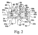
図1は、本発明の或る形態による椎間移植片20を示している。椎間移植片20は、長手方向軸Lに沿って伸長し、概括的には拡張可能な本体22と拡張部材24とで構成されている。後で更に詳しく説明するが、拡張部材24は、拡張可能な本体22を、図6に示す最初の形態から、図7に示すように本体22が概ね横軸Tに沿って拡張する拡張形態に移行させるように働く。
FIG. 1 illustrates an
椎間移植片20の構成要素は、生体適合性を有する材料で作られている。本発明の或る形態では、椎間移植片20の構成要素は、例えば、ステンレス鋼及びステンレス鋼合金、チタニウム及びチタニウム合金、形状記憶合金、コバルトクロム合金、又はその他の適した金属材料のような、金属材料で作られている。本発明の別の実施形態では、椎間移植片20の構成要素は、例えば、ポリマー材料、セラミック材料、強化複合材料、骨、骨置換材料、又はその他の適した非金属材料のような、非金属材料で作られている。
The components of the
図1から図4の各図は、拡張可能な本体22について更に詳細を示している。本発明の図示の実施形態では、拡張可能な本体22は、移植片20内部への又はこれを貫通する骨の成長を助長又は促進して隣接する椎体の間の関節固定を達成する特徴を含んでいる拡張可能な融合ケージとして構成されており、詳細を以下に説明する。しかしながら、本発明の他の実施形態では、拡張可能な本体22は拡張可能なスペーサ又はプラグとして構成されている旨理解されたい。
1 to 4 show further details of the
本発明の或る実施形態では、融合ケージ22は、概ね長手方向軸Lに沿って伸長する上側及び下側壁30、32と、上側及び下側壁30、32の相対する端部分の間を横方向に伸長しそれらを相互に接続する一対の端壁34、36を備えている。上側及び下側軸壁30、32並びに横端壁34、36は協働して、概ね長手方向軸Lに沿って伸長する内側チャンバ40を画定している。図示の実施形態の融合ケージ22では、軸壁30、32と横壁34、36とは、融合ケージ22に、略矩形の軸方向断面を与えている。しかしながら、融合ケージ22は他の形状及び構成も考えられ、それらも本発明の範囲に含まれるものと理解されたい。
In some embodiments of the present invention, the
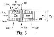
図3に示すように、融合ケージ22は、幅w1を有する端部分22a、22bと、幅w2を有する中央部分22cを含んでいる。中央部分22cの幅w2は、隣接する椎体に係合させるための、融合ケージ22の中央部分に隣接する表面積を広げるために、端部分22a、22bの幅w1よりも幾分大きく作られている。また、端部分22a、22bの幅w1を小さくすることにより、上側及び下側壁30、32の可撓性が増し、融合ケージ22を拡張する際に、上側及び下側壁30、32を外向きに変形させ易くなる。しかしながら、本発明の他の実施形態では、融合ケージ22は実質的に均一な幅を有する構成になっている旨理解されたい。
As shown in FIG. 3, the
本発明の或る態様では、上側及び下側壁30、32は、上側及び下側壁30、32が拡張部材24を介して互いに対して外向きに変位できるやり方で端壁34、36に結合されている。本発明の別の態様では、拡張部材24は、上側及び下側壁30、32と協働して、上側及び下側壁30、32を互いに対して外方向に撓ませながら変形させ、融合ケージ22を概ね横軸Tに沿って外向きに拡張させる(図7)。このような外向きの変形は、主として、上側及び下側壁30、32の可撓的性質、及び/又は上側及び下側壁30、32と端壁34、36の間の可撓的相互接続に依るものである。或る実施形態では、上側及び下側壁30、32の外向きの変形は、長手方向軸Lに沿って伸張する凸状の所定の外側曲率を画定しており(図7)、これは、後に述べるように、隣接する椎体の凹状面曲率に対応している。本発明の別の態様では、上側及び下側壁30、32は、端壁34、36と一体に形成され、一個の単一部品の融合ケージユニット22を形成している。しかしながら、上側及び下側壁30、32並びに端壁34、36は、別々に作ってから一体に接合して、多部品構成の融合ケージアッセンブリを形成することも考えられる。
In one aspect of the invention, the upper and
融合ケージ22の上側及び下側壁30、32は、上側及び下側面50、52を画定している。本発明の或る実施形態では、上側及び下側面50、52は、端壁34、36に隣接する上側支承面54a、54bと下側支承面56a、56bを画定している。以下に述べるように、上側及び下側支承面54a、54b及び56a、56bは、上側及び下側椎体VU、VLの皮質縁/輪状骨起領域に接してこれを支承し(図6から図8)、融合ケージ22に作用する圧縮力の大部分に対する支持と抵抗を提供する。本発明の図示の実施形態では、上側及び下側支承面54a、54b及び56a、56bは、実質的に滑らかで段差、突出、突起、凸凹が無い。しかしながら、他の実施形態では、上側及び下側支承面は、椎骨と係合しこれを把持するのを支援する錨着用の造形を画定している旨理解されたい。
The upper and
本発明の更に別の実施形態では、融合ケージ22の上側及び下側面50、52は、上側及び下側支承面54a、54b及び56a、56bの間に軸方向に配置された複数の錨着要素を含んでいる。錨着要素は、隣接する椎骨VU、VLと係合して、融合ケージ22の移動を防止又は阻止し、及び/又は椎間円板空間内への移植の後、融合ケージ22の上に骨が成長し易くなるように作られている。或る実施形態では、錨着要素は、上側及び下側面50、52から突き出ている複数の歯又は突起部60を備えている。別の実施形態では、錨着要素は、上側及び下側面50、52に切り込まれた複数の溝62を備えている。しかしながら、融合ケージ22と共に使用するものとして、錨着要素の他の組み合わせ及び/又は構成も考えられ、例えば、スパイク、ねじ、畝、隆起、粗面、又は椎骨組織への錨着に適したその他の要素又は造形のような、上側及び下側面50、52から伸張する他の造形又は要素も考えられる旨理解されたい。また、本発明の別の実施形態では、融合ケージ22の上側及び下側面50、52は、必ずしも錨着要素を含んでいる必要はなく、代わりに、面突起や面の凸凹の無い実質的に滑らかな面でもよいものと理解されたい。
In yet another embodiment of the invention, the upper and
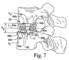
融合ケージ22の図示の実施形態では、歯60は、融合ケージ22の中央部分22cを横切って横方向に伸張する列として配置されている。融合ケージ22は、上側及び下側面50、52から伸張する2列の歯60を有するように示されているが、歯の列は1列又は3列以上の構成も考えられる旨理解されたい。加えて、歯60は、他の方向、例えば、長手方向軸Lに平行な方向に向けて配置しもよいし、或いは、長手方向軸Lに対して斜角に配置してもよい旨理解されたい。1列又はそれ以上の列の歯60は、融合ケージ22の端部分22a、22bを含めて、上側及び下側面50、52の他の部分から伸張していてもよい旨理解されたい。或る実施形態では、歯60は三角形の構成をしているが、他の形状及び構成の歯も、本発明の範囲に含まれると考えられる。図7に示すように、融合ケージ22が拡張形態に移行すると、歯60は隣接する椎体VU、VLの椎骨終板と係合し/これに突き当たって、融合ケージ22が移動すること、及び円板空間から押し出される虞を防止又は阻止する。
In the illustrated embodiment of the
融合ケージ22の図示の実施形態では、溝62は、融合ケージ22の端部分22a、22bを横切って横方向に伸張する列として配置されている。融合ケージ22は、上側及び下側面50、52それぞれに形成された10個の溝60を有するように示されているが、溝60の数はいくつでもよいものと理解されたい。また、溝62は、他の方向、例えば、長手方向軸Lに平行な方向、又は長手方向軸Lに対して斜角に向けて配置してもよい旨理解されたい。また、溝は、中央部分22cを含め、融合ケージ22の他の部分に切り込んでもよいものと理解されたい。
In the illustrated embodiment of the
本発明の或る実施形態では、溝62は、上側及び下側面50、52に低地部又はチャネルを切り込むことにより形成されているが、それらは間隔を空けて配置され、上側及び下側面50、52と実質的に同一面となるランド又は台地部64を画定している。縁部又は角部66は、溝62とランド64のが出会う点に画定される。或る実施形態では、溝62は、ランド64の幅よりも広い溝幅及び溝深さを有するように作られている。しかしながら、溝62は他の構成も考えられる。また、図示の実施形態では、溝62は、半径又は曲率が実質的に一様の実質的に円形構成を有している。しかしながら、溝62は、例えば、円弧状又は弓状の溝、V字型又はU字型の溝、或いは他の適した溝形状又は構成のような、他の形状及び構成も考えられる。図7に示すように、融合ケージ22が拡張形態に移行すると、ランド64は隣接する椎体VU、VLの椎骨終板と係合して、溝62を椎骨に近接して位置決めし、骨組織を中に受け入れ、及び/又は融合ケージ22上へ骨が成長し易いようにする。また、溝62とランド64の間に形成された縁部66は、融合ケージ22が移動すること、及び円板空間から押し出される虞を防止又は阻止するのを支援する。
In some embodiments of the invention, the
図1と図3を見れば良く分かるように、本発明の或る実施形態では、融合ケージ22の上側及び下側壁30、32は、上側及び下側面50、52を貫通して伸張し内側チャンバ40と連通する、骨の内部成長用の複数の孔又は窓80a、80bを画定している。理解頂けるように、骨の内部成長用の孔80a、80bは、隣接する椎体から融合ケージ22内へ、そして恐らくは融合ケージ22を貫通して、骨が成長できるようにしている。融合ケージ22は、上側及び下側各壁30、32を貫通して伸長する一対の骨の内部部成長用の孔80a、80bを有するように示されているが、融合ケージ22は、骨の内部成長用の孔を幾つ含んでいてもよく、融合ケージの略全長に沿って伸張する単一の骨の内部成長用の孔を有していてもよいし、3つ又はそれ以上の骨の内部成長用の孔を融合ケージ22の長さに沿う様々な位置に配置してもよい旨理解されたい。また、骨の内部成長用の孔80a、80bは、長手方向軸Lに沿って伸張するスロット長と、融合ケージ22の幅の約2分の1に亘って伸張するスロット幅とを有する矩形のスロット様構成を有するように示されているが、骨の内部成長用の孔の形状、構成、及び寸法は他のものも考えられる旨理解されたい。また、骨の内部成長用の孔80a、80bは、内側チャンバ40と連通しているように示され、説明されているが、他の実施形態では、孔80a、80bは、必ずしも上側及び下側壁30、32を貫通して伸長している必要はないものと理解されたい。
As best seen in FIGS. 1 and 3, in one embodiment of the present invention, the upper and
図1と図4を見れば良く分かるように、融合ケージ22の図示の実施形態では、軸孔82は、端壁34、36を貫通して内側チャンバ40と連通している。以下に更に詳しく説明するように、軸孔82は、拡張部材24と係合させて融合ケージ22を拡張形態へ移行させ易くするために、器具のシャフト部分をその中に通すことのできる寸法に作られている。加えて、軸孔82は、融合ケージ22の後方又は前方からその内側チャンバ40内へと、隣接する椎体から骨が成長できるようにもしている。
As best seen in FIGS. 1 and 4, in the illustrated embodiment of the
図1と図2に示すように、本発明の或る実施形態では、内側チャンバ40は、融合ケージ22の長さに沿って配置された複数の区別できる分室又は区間を含んでいる。融合ケージ22の図示の実施形態では、内側チャンバ40は、融合ケージ22の端部分22a、22bに隣接して配置されている端分室90a、90bと、融合ケージ22の中央部分22cに隣接して配置されている中間又は中央分室90cを含んでいる。しかしながら、内側チャンバ40は、1つの分室、2つの分室、4つ又はそれ以上の分室を含め、任意の数の分室を含んでいてもよい旨理解されたい。本発明の図示の実施形態では、チャンバ分室90a、90b、90cは、それぞれ融合ケージ22を横方向に貫通して伸びており、融合ケージ22を拡張させるための可撓性を高めると共に、融合ケージ22に開放された側面を設けて横方向から内側チャンバ内へ骨が成長できるようにしている。
As shown in FIGS. 1 and 2, in one embodiment of the present invention, the
融合ケージ22の図示の実施形態では、端分室90a、90bは、それぞれ略長楕円形状又は長円形/楕円形の構成を有しており、上側及び下側壁30、32の中間分室90Cに隣接する内面は互いに向けて内向きに傾斜して、一対の相対する傾斜面92a、92bを画定している。中央分室90cは、円弧状の構成を有し、上側及び下側壁30、32の内面は、拡張ピン24(図5)の外面100と実質的に同じ曲率を有する一対の相対する凹状面94a、94bを画定している。端分室90a、90bの傾斜面92a、92bと中央分室90cの凹状面94a、94bとの間の交差点は、中央分室90cの両側に位置する相対する先端又は頂点96a、96b及び98a、98bを画定している。融合ケージ22の図示の実施形態は、内側チャンバ40と分室90a、90b、90cが特定の形状及び構成を有するように示されているが、他の適した形状及び構成も本発明の範囲内に含まれるものと考えられる旨理解されたい。
In the illustrated embodiment of the
図5は、本発明の或る実施形態による拡張部材24を示している。図示の実施形態では、拡張部材24は、湾曲した外面100を有し、外径dlを有する略円形の外側断面を画定している細長いピンとして構成されている。しかしながら、本発明と共に使用する場合には、拡張ピン24は、例えば、楕円形、長方形、又は六角形形状のピンなど、他の形状及び構成も考えられる旨理解されたい。以下に詳しく説明するように、拡張ピン24の湾曲した外面100は、融合ケージ22を拡張形態に移行させるために拡張ピン24を内側チャンバ40に沿って軸方向に変位させる際に、上側及び下側壁30、32の傾斜面92a、92bに沿って滑動する。また、孔102は、少なくとも部分的には拡張ピン24を通って伸びており、そこに外科処置器具の遠位端部分を受け入れて、拡張ピン24を融合ケージ22の内側チャンバ40に沿って変位させ、案内することができる寸法に作られている。或る実施形態では、孔102は、略円形断面を有し、外科処置器具の遠位部分に螺合できるようにねじが切られている。しかしながら、本発明と共に使用する場合には、孔102は他の形状及び構成も考えられる旨理解されたい。
FIG. 5 illustrates an
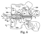
次に図6は、移植片20が初期の非拡張形態で上側及び下側椎体VU、VLの間の円板空間内に配置された状態を示している。本発明の或る実施形態による外科処置器具200は、椎間移植片20と係合し、移植片20を円板空間に挿入して融合ケージ22を図7に示す拡張形態に移行させるのを支援する。図示の実施形態では、外科処置器具200は、概括的には、外側スリーブ202と、内側駆動シャフト204を含んでいる。外科処置器具200は、椎間移植片20の操作及び取り扱いを支援するハンドル(図示せず)を含んでいてもよい。しかしながら、外科処置器具は、本発明と共に使用する場合には他の適した種類及び構成も考えられ、その要素と操作は、ここに図示し説明している外科処置器具200の実施形態とは異なっていてもよいと理解されたい。例えば、本発明と共に使用するのに適した別の種類の器具は、Liu他への米国特許第6,436,140号に図示し説明されており、同特許の内容を参考文献としてここに援用する。
Next, FIG. 6 shows a condition in which the
外科処置器具200の外側スリーブ202は、融合ケージ22にしっかりと係合するように作られた遠位端部分202aを有している。本発明の或る実施形態では、器具200は、スリーブ202の遠位端部から軸方向に伸張し、相対して互いに向けて内向きに伸張する横フランジ部(図示せず)を含んでいる一対の尖部(図示せず)を含んでいる。理解頂けるように、融合ケージ22の端分室90a、90cの何れかに横フランジを挿入することにより、外側スリーブ202を融合ケージ22に対して固定する機能が発揮される。しかしながら、スリーブ202と融合ケージ22の間の係合は他の様式も考えられ、例えば、螺合、当接係合、クランプ式係合、鍵式係合、さねはぎ係合、摩擦係合、又はその他適した係合手段などがあると理解されたい。
The
内側駆動シャフト204は、外側スリーブ202内に配置され、融合ケージ22の端壁34の軸孔82を通って伸張し拡張ピン24と係合する遠位端部分204を含んでいる。上記のように、或る実施形態では、駆動シャフト204の遠位端部分204aは、拡張ピン24に形成されたねじ付穴102の中に螺合して、駆動シャフト204を拡張ピン24としっかりと係合する。しかしながら、別の実施形態では、駆動シャフト204の遠位端部分204aと拡張ピン24の穴102は、必ずしもねじが切られている必要はなく、代わりにそれぞれ実質的に滑らかな外面と内面を画定していてもよいと理解されたい。また、駆動シャフト204と融合ケージ22の間の係合は他の様式も考えられ、例えば、当接係合、クランプ式係合、鍵式係合、さねはぎ係合、摩擦係合、又はその他適した係合手段などがあると理解されたい。
理解頂けるように、駆動シャフト204を矢印Aの方向へ軸方向に変位させると、対応して、拡張ピン202が内側チャンバ40を通って変位し、融合ケージ22を図7に示す完全拡張形態に向けて移行させる。或る実施形態では、例えば、Liu他への米国特許第6,436,140号に示すように、駆動シャフト204と外側スリーブ202の間の螺合を介して、駆動シャフト204を軸方向に変位させる。このようにして、駆動シャフト204の回転によって、拡張ピン24の軸方向変位が起こる。別の実施形態では、駆動シャフト204は、概括的には、融合ケージ22の端壁34の軸孔82内に螺合するスクリュー又はボルトとして構成され、駆動シャフト204を回転させると拡張ピン24が軸方向に変位するようになっている。なお、そうはいうものの、融合ケージ22の内側チャンバ40を通って拡張ピン24を軸方向変位させるための他の適した装置及び技法も、本発明の範囲に含まれるものとして考えられる旨理解されたい。
As can be seen, when the
理解頂けるように、拡張ピン24を内側チャンバ40の端分室90aから中央分室90cに向けて軸方向に変位させると、拡張ピン24の外側面100は斜面92a、92bと滑動的に係合する。その結果、融合ケージ22の上側及び下側壁30、32は、互いに離され、横軸Tに沿って外向きに変形して、融合ケージ22を図6に示す初期の非拡張形態から図7に示す拡張形態に移行させる。拡張ピン24を、内側チャンバ40の中央分室内に位置するまで軸方向に更に変位させ、拡張ピン24が、相対する凹状面94a、94bで形成される窪んだ領域内に入って相対する先端/頂点部96a、96bと98a、98bの間に捉えられた状態にする。
As can be seen, when the
拡張ピン24が相対する凹状面94a、94b内の相対する先端/頂点部96a、96bと98a、98bの間に入ると、拡張ピン24は、中央分室90c内に保持され、それ以上軸方向に変位するのを阻止されるので、融合ケージ22は、駆動シャフト204が拡張ピン24から外された後も、図7に示す拡張形態に維持される旨理解されたい。また、融合ケージ22を拡張させる際、拡張ピン24が一対の相対する先端/頂点部96a、96bを越えて中央分室90cに入ってしまうと、器具200の駆動シャフト204に働いていた直線状の駆動力又は回転トルクは急に低下する旨理解されたい。駆動力又はトルクが急激に落ち込むことにより、外科医は、拡張ピン24が中央分室90c内に正しく配置され、所望の拡張量が得られたことを、感覚的に認識することができる。
As the
図6に示すように、融合ケージ22は、上側及び下側椎骨VU、VLの分離距離(即ち、円板空間高)より幾分低い初期の非拡張高h1を有している。しかしながら、図7に示すように、融合ケージ22の拡張により、融合ケージ22の全高は、円板空間の高さと実質的に等しい拡張高h2まで伸ばされる。理解頂けるように、融合ケージ22の初期高さh1と拡張高h2の差は、拡張ピン24の直径d1(又は高さ)(図5)と、融合ケージ22の中央分室90cの凹状面94a、94bの間の非拡張時の距離d2(図6)との間の差に対応する。従って、融合ケージ22の拡張は、選択直径d1(又は高さ)を有する拡張ピンを提供すること、及び/又は中央分室90cが凹状面94aと94bの間の選択的非拡張時距離d2を有するようにすることにより、容易且つ正確に制御することができる。
As shown in FIG. 6, the
本発明の図示の実施形態では、拡張ピン24を、内側チャンバ40を通って軸方向に変位させると、融合ケージ22が横軸Tに沿って拡張されることになる。しかしながら、本発明の他の実施形態では、融合ケージ22と拡張ピン24は、拡張ピン24を融合ケージ22に対して横方向、回転方向、及び/又は軸回転方向に変位させると、融合ケージ22が横軸Tに沿って拡張するように構成されていると理解されたい。例えば、本発明の代わりの実施形態では、拡張ピン24は、長円形又はカム様の構成を有するように作られており、拡張ピン24を中央分室90c内で回転させると、融合ケージ22が拡張するようになっている。また、本発明の図示の実施形態は、拡張ピン24を、端分室90aから中央分室90cに向けて内側チャンバを通して軸方向に押し又は駆動するのに応じて、融合ケージ22が拡張するように示しているが、融合ケージ22は、拡張ピン24を、端分室90aから中央分室90cに向けて内側チャンバ通して軸方向に引っ張り又は引き出すの応じて、融合ケージ22が拡張するように構成してもよい旨理解されたい。
In the illustrated embodiment of the present invention, when the
図7に示すように、融合ケージ22が拡張形態に移行すると、上側及び下側壁30、32は、横軸Tに沿って外向きに互いに離れる方向に変形して、融合ケージ22の全高h2を伸ばす。上側及び下側壁30、32の端部分は端壁34、36と一体に接続されているので、上側及び下側壁30、32の端部分は比較的静止した状態に保持され、融合ケージ22の端部分22a、22bに隣接する部分の拡張は制限される。しかしながら、上側及び下側壁30、32の中央部分は相互接続されていないので、融合ケージ22は、主にその中央部分に沿って拡張する。その結果、融合ケージ22が拡張すると、上側及び下側壁30、32は、それぞれ長手方向軸Lに沿って伸張する所定の凸状曲率を形成する。外側に変形した上側及び下側壁30、32の凸状曲率は、隣接する椎体VU、VLの椎骨終板が形成する前方から後方への面の曲率Cに実質的に対応している。融合ケージ22の拡張に続き、外科処置器具200を椎間移植片20から係合解除して、患者の体内から取り出す。
As shown in FIG. 7, when the
本発明の更に別の態様では、上側及び下側椎体VU、VLから、上側及び下側骨成長用孔80a、80bを通り融合ケージ22の中へそしてそれを貫いて骨が成長し易いようにし又は成長を促すために、骨成長促進物質300(図7及び図8)が、融合ケージ22の内側チャンバ40に充填されている。或る実施形態では、骨成長促進物質300は、移植骨片材料、骨形成蛋白質(BMP)、又はその他の適した骨成長促進材料又は物質から成り、そのような物質としては、限定するわけではないが、骨粉又は骨髄、脱塩骨基質(DBM)、間葉幹細胞、及び/又はLIM鉱化蛋白質(LMP)が含まれる。なお、骨成長促進物質300は、適した担体と共に使用しても担体を用いずに使用してもよいと理解されたい。
In yet another aspect of the invention, bone grows from the upper and lower vertebral bodies V U , V L through the upper and lower
本発明の或る実施形態では、骨成長促進物質300は、融合ケージ22の拡張に引き続いて、端壁34の軸孔82を通して内側チャンバ40に注入される。別の実施形態では、骨成長促進物質300は、融合ケージ22の挿入及び拡張に先立ち(拡張ピン24が初期位置として端分室90a内に配置されているとき)、内側チャンバ40の端分室90bに事前に充填されている。更に別の実施形態では、融合ケージ22と拡張ピン24は、融合ケージ22の挿入及び拡張に先立ち、骨成長促進物質300を分室90a、90bそれぞれに事前に充填できるように構成されている。
In one embodiment of the invention, bone
以上、椎間移植片20の要素及び作用について図示し説明してきたが、以下、本発明の或る実施形態による、椎間移植片20を円板空間内に移植するための技法を説明する。しかしながら、他の移植技法及び手法も考えられること、及び、以下の技法により本発明の範囲を限定する意図は何ら無いことを理解されたい。
Having described and illustrated the elements and operation of the
本発明の或る実施形態では、脊柱へのアクセスと、椎間移植片20の円板空間への挿入は、後方外科的進入法により行われる。しかしながら、このアクセスと椎間移植片20の円板空間への挿入は、例えば、前方進入法又は側方進入法のような他の外科的処置によって行うこともできると理解されたい。本発明の別の実施形態では、椎間移植片20は、腰椎椎体から成る上側及び下側椎体VU、VLを備えた脊椎の腰椎部位を治療するのに使用される。しかしながら、本発明は、例えば、脊柱の頸部、胸部、又は仙骨部位のような脊椎の他の部分にも適用可能である旨理解されたい。
In certain embodiments of the invention, access to the spinal column and insertion of the
最初に、処置対象の脊柱を確認し、既知の外科処置技法を使用して後方進入法によりアクセスする。天然椎間円板の少なくとも一部を、全又は部分椎間板切除術により除去して、上側及び下側椎体VU、VLの間に椎間移植片20を受け入れるための開口部を設ける。次いで、円板空間を、天然の円板空間高に実質的に等しい高さにまで伸延する。椎間移植片20の挿入に先立ち、各種切削工具及び/又は他の種類の外科処置器具(例えば、鋭匙(curettes)、のみ(chisel))を使用して、円板空間及び上側及び下側椎体VUとVLの終板に前処置を施す。椎体VU、VLの前処置に適する切削器具の一例は、Liu他への米国特許第6,610,089号に示されており、その内容をここに参考文献として援用する。しかしながら、本発明と共に使用する場合は、切削器具は、他の種類及び構成も考えられる旨理解されたい。
Initially, the spine to be treated is identified and accessed by posterior approach using known surgical techniques. At least a portion of the natural disc is removed by full or partial discectomy to provide an opening for receiving the
本発明の或る実施形態では、椎体VU、VLの前処置に使用される切削器具は、骨組織を椎骨終板から切り取って除去するが、終板の自然な凹状曲率を実質的に維持し、椎骨終板の前方/後方部分に隣接する皮質縁/輪状骨起領域への切り込みを回避するようになっている。切削器具は、切削処置中に出た骨くず又は骨片を収集し、その後、融合ケージ22の内側チャンバへ挿入して関節固定を促すのに備えている。図6及び図7に示すように、前処置された椎骨終板は、それぞれ前後方向に全体的に凹状になっている陥凹領域又は面曲率Cを画定している。理解頂けるように、椎体VU、VLにより画定された陥凹領域又は面曲率Cは、拡張した融合ケージ22の外側に向けて変形した上側及び下側壁30、32を受け入れて、融合ケージの上側及び下側面50、52及び融合ケージ22内に配置された骨成長物質300が、椎体VU、VLの海綿状の海綿骨の組織(spongy cancellous bone tissue)に近接して配置され、融合が促進されるようにしている。
In some embodiments of the present invention, the cutting instrument used for pretreatment of the vertebral bodies V U , V L cuts and removes bone tissue from the vertebral endplate, but substantially eliminates the natural concave curvature of the endplate. In order to avoid incision into the cortical margin / annular ossification region adjacent to the anterior / posterior portion of the vertebral endplate. The cutting instrument is prepared to collect bone debris or bone fragments that emerge during the cutting procedure and then insert them into the inner chamber of the
椎骨終板の前処理に続いて、適した挿入技法、例えば、打ち込み又は押し込み挿入のような挿入法を使用して、円板空間内に椎間移植片20を挿入する。椎間移植片20は、円板空間高よりも幾分低い初期高hlを有する非拡張形態で円板空間に挿入されるので、円板空間の過剰伸延は回避され、神経の伸延はできる限り小さく抑えられる。本発明の更に別の実施形態では、椎間移植片20は、内視鏡機器、小径管又はカニューレを使用して、又は他の侵襲性を最小限に抑えた外科処置技法で、侵襲性を最小限に抑えたやり方で(即ち、小さいアクセス口を介して)円板空間に挿入される。しかしながら、移植片20は、従来の外科処置法及び技法を用いて、円板空間に挿入してもよいと理解されたい。椎間移植片20の円板空間への挿入に続いて、融合ケージ22を図7に示す(拡張後の高さh2を有する)形態に拡張して、所望の円板空間高を復元及び/又は維持する。先に述べたように、融合ケージ22が拡張形態へ移行すると、上側及び下側壁30、32が、図6に示す実質的に平坦な形態から図7に示す円弧又は湾曲形態へと外側に向かって変形する。
Following pretreatment of the vertebral endplate, the
理解頂けるように、椎骨は、椎体の外側領域を取り巻くように広がっている硬い皮質骨物質と、皮質骨物質の内側の軟らかい海綿骨の物質、すなわち海綿状の骨の物質(cancellous or spongiseum bone material)とを備えている。図7及び図8に示すように、融合ケージ22の上側及び下側前方/後方支承面54a、54b及び56a、56bは、融合ケージ22に働く圧縮力に抗し、且つ比較的軟らかい海綿骨の組織、すなわち海綿状の骨の組織(cancellous or spongiseum bone tissue)に沈下する可能性を少なくするために、上側及び下側椎体VU、VLそれぞれの皮質縁/輪状骨起領域を支承するように配置されている。また、融合ケージを図7に示す拡張形態に移行させることにより、上側及び下側面50、52から伸張している歯60が椎骨終板の中に埋め込まれ又は打ち込まれ、融合ケージ22が円板空間から移動すること及び押し出される虞に抵抗する。また、上側及び下側椎体VU、VLにより画定された凹状面曲率C内に、外向きに変形した上側及び下側壁30、32を配置すると、融合ケージ22の安定性が高まると共に、融合ケージ22が円板空間から移動すること及び押し出される虞が小さくなる。更に、外向きに変形した上側及び下側壁30、32を上側及び下側椎体VU、VLの海綿骨の組織、すなわち海綿状の骨の組織に近接させ又は直接接触させて配置すると、骨が、溝62の中に、及び/又は孔80a、80bを通って内側チャンバ40の中まで成長し易くなる。
As can be seen, vertebrae are composed of hard cortical bone material that extends around the outer area of the vertebral body, and soft cancellous bone material inside the cortical bone material, i.e., cancellous or spongiseum bone. material). As shown in FIGS. 7 and 8, the upper and lower anterior /
本発明の更に別の態様では、内側チャンバ40の中央分室90c内に拡張ピン24を配置すると、融合ケージ22の上側及び下側壁30、32に追加的な支持及び剛性が与えられ、椎体VU、VLからの圧縮荷重、特に、ピンがなければ内部支持部材を欠くことになる融合ケージ22の中央部分22c付近に掛かる圧縮荷重に抗することができるようになる。椎間移植片20は、拡張ピン24と融合ケージ22の上側及び下側壁30、32との係合だけによって拡張形態に維持されているが、融合ケージ22の支持力を高めるため、特に過剰な椎骨負荷及び/又は不安定さが伴うような場合には、1つ又は複数の補助的な内部固定要素を使用してもよいと理解されたい。また、1つ又は複数の椎間移植片20を円板空間内に挿入し拡張した後に、過度の不安定さがまだ残っている場合には、補助的な外付きの椎骨内固定要素及び/又は安定化技法も使用できるものと理解されたい。
In yet another aspect of the present invention, the placement of the
融合ケージ22が完全に拡張すると、骨成長促進物質300を融合ケージ22の内側チャンバ40に充填して、骨が、上側及び下側椎体VU、VLから、骨成長用の孔80a、80bを通り、融合ケージ22の中に、そして恐らくはそれを通って成長するのを支援又は促進する。また、融合を更に促進するために、移植骨片、自己移植骨の細片(morselized autograft bone)又は同様の種類の物質を拡大した融合ケージ22に横方向に隣接させて配置してもよい。上記のように、本発明の或る実施形態では、骨成長促進物質300は、融合ケージの挿入及び拡張に先立って内側チャンバ40の端分室90bに事前に充填され、その後、融合ケージ22の挿入と拡張に続いて、骨成長促進物質30が、内側チャンバ40の端分室90aに充填される。その結果、骨成長促進物質300は、骨の内部成長用の孔80a、80bに隣接して拡張ピン24の何れの側にも配置され、融合し易くする。
When the
図8に示す本発明の更に別の実施形態では、一対の椎間移植片20a、20bが、円板空間内で左右相称に横に並べて配置されている。しかしながら、椎間移植片20を1つ、円板空間内で片側だけに又は中央に配置することも、本発明の範囲に含まれるものと理解されたい。上側及び下側椎体VU、VLの間の融合を更に促進するために、移植骨片、自己移植骨の細片、又は骨成長促進物質を、移植片20a、20b、の間の領域内に配置してもよい。
In yet another embodiment of the invention shown in FIG. 8, a pair of
以上、本発明を図面及び上記説明で図示し詳しく説明してきたが、それらは説明を目的としたものであって、何ら制約を課すものではなく、好適な実施形態を示し説明したに過ぎず、本発明の精神に含まれる全ての変更及び修正は保護の対象とされることを要望する旨理解頂きたい。 The present invention has been illustrated and described in detail with reference to the drawings and the above description, but these are for the purpose of explanation, do not impose any restrictions, and merely show and explain preferred embodiments. It should be understood that all changes and modifications within the spirit of the invention are desired to be protected.
Claims (35)
長手方向軸を有し、且つ横軸に沿って離間して配置された第1軸壁及び第2軸壁を含んでいる本体であって、前記第1軸壁は、第1の一対の両端部分を含んでおり、前記第2軸壁は第2の一対の両端部分を含んでおり、前記第1の一対の両端部分と前記第2の一対の両端部分とは相互に接続されている、本体と、
前記本体を前記横軸に沿って拡張させるために、前記第1軸壁及び前記第2軸壁と協働する拡張部材とを備えている、移植片。 In an expandable intervertebral implant,
A body having a first axis wall and a second axis wall having a longitudinal axis and spaced apart along a horizontal axis, the first axis wall comprising a first pair of opposite ends The second shaft wall includes a second pair of both end portions, and the first pair of both end portions and the second pair of both end portions are connected to each other. The body,
An implant comprising an expansion member that cooperates with the first and second axial walls to expand the body along the transverse axis.
前記拡張部材を前記内側チャンバ内で移動させると、前記拡張部材は、前記第1軸壁及び前記第2軸壁と係合して前記本体を前記横軸に沿って拡張させる、請求項1に記載の移植片。 The body defines an inner chamber dimensioned to receive the expansion member;
2. The expansion member according to claim 1, wherein when the expansion member is moved in the inner chamber, the expansion member engages with the first shaft wall and the second shaft wall to expand the main body along the horizontal axis. The described graft.
前記拡張部材を前記内側チャンバ内で軸方向に変位させると、前記拡張部材は、前記第1軸壁及び前記第2軸壁と係合して、前記本体を前記横軸に沿って拡張させ、
前記拡張部材は、前記内側チャンバの概ね全幅に亘る長さを有する細長いピンを含んでいる、請求項1に記載の移植片。 The body defines an inner chamber dimensioned to receive the expansion member therein;
When the expansion member is displaced in the axial direction in the inner chamber, the expansion member engages with the first shaft wall and the second shaft wall to expand the main body along the horizontal axis,
The implant of claim 1, wherein the expansion member includes an elongate pin having a length that spans substantially the entire width of the inner chamber.
長手方向軸を有し、且つ概ね前記長手方向軸に沿って伸張し横軸に沿って離間して配置された第1軸壁及び第2軸壁を含んでいる、本体と、
前記第1軸壁及び前記第2軸壁が外向きに変形して、前記長手方向軸に沿って凸状の所定の外側曲率を画定するように、前記第1軸壁及び前記第2軸壁と協働して前記本体を前記横軸に沿って拡張する、拡張部材とを備えている、移植片。 In an expandable intervertebral implant,
A body having a longitudinal axis and including a first axial wall and a second axial wall extending generally along the longitudinal axis and spaced apart along a transverse axis;
The first axial wall and the second axial wall such that the first axial wall and the second axial wall are deformed outwardly to define a predetermined outer curvature that is convex along the longitudinal axis. And an expansion member that cooperates with and expands the body along the transverse axis.
前記拡張部材を前記内側チャンバ内で移動させると、前記拡張部材は、前記第1軸壁及び前記第2軸壁と係合して、前記第1軸壁及び前記第2軸壁を前記横軸に沿って外向きに変形させる、請求項30に記載の移植片。 The body defines an inner chamber dimensioned to receive the expansion member;
When the expansion member is moved in the inner chamber, the expansion member engages with the first shaft wall and the second shaft wall, and the first shaft wall and the second shaft wall are moved along the horizontal axis. 32. The implant of claim 30, wherein the implant is deformed outwardly along the axis.
前記移植片は、隣接する椎体と融合し易くするために前記内側チャンバ内に配置された骨成長促進物質を更に含んでいる、請求項33に記載の移植片。 The first axial wall and the second axial wall each define at least one bone ingrowth hole formed therethrough and in communication with the inner chamber;
34. The implant of claim 33, further comprising a bone growth promoting substance disposed within the inner chamber to facilitate fusion with an adjacent vertebral body.
Applications Claiming Priority (2)
| Application Number | Priority Date | Filing Date | Title |
|---|---|---|---|
| US10/734,041 US7569074B2 (en) | 2003-12-11 | 2003-12-11 | Expandable intervertebral implant |
| PCT/US2004/041873 WO2005058209A2 (en) | 2003-12-11 | 2004-12-09 | Expandable intervertebral implant |
Publications (2)
| Publication Number | Publication Date |
|---|---|
| JP2007513718A true JP2007513718A (en) | 2007-05-31 |
| JP2007513718A5 JP2007513718A5 (en) | 2008-02-07 |
Family
ID=34653284
Family Applications (1)
| Application Number | Title | Priority Date | Filing Date |
|---|---|---|---|
| JP2006544103A Pending JP2007513718A (en) | 2003-12-11 | 2004-12-09 | Expandable intervertebral implant |
Country Status (9)
| Country | Link |
|---|---|
| US (2) | US7569074B2 (en) |
| EP (1) | EP1706075B1 (en) |
| JP (1) | JP2007513718A (en) |
| CN (1) | CN100571659C (en) |
| AT (1) | ATE493950T1 (en) |
| AU (1) | AU2004299064A1 (en) |
| CA (1) | CA2549106A1 (en) |
| DE (1) | DE602004030947D1 (en) |
| WO (1) | WO2005058209A2 (en) |
Cited By (2)
| Publication number | Priority date | Publication date | Assignee | Title |
|---|---|---|---|---|
| JP2014516289A (en) * | 2011-03-30 | 2014-07-10 | トリニティ・オーソペディックス・リミテッド・ライアビリティ・カンパニー | Articulating interbody cage and method for interbody cage |
| US9510955B2 (en) | 2012-05-18 | 2016-12-06 | Trinity Orthopedics, Llc | Articulating interbody cage and methods thereof |
Families Citing this family (170)
| Publication number | Priority date | Publication date | Assignee | Title |
|---|---|---|---|---|
| US6793678B2 (en) | 2002-06-27 | 2004-09-21 | Depuy Acromed, Inc. | Prosthetic intervertebral motion disc having dampening |
| US7125425B2 (en) * | 2002-10-21 | 2006-10-24 | Sdgi Holdings, Inc. | Systems and techniques for restoring and maintaining intervertebral anatomy |
| US7828849B2 (en) | 2003-02-03 | 2010-11-09 | Warsaw Orthopedic, Inc. | Expanding interbody implant and articulating inserter and method |
| JP2006517842A (en) | 2003-02-14 | 2006-08-03 | デピュイ スパイン、インコーポレイテッド | Apparatus and method for in situ forming intervertebral fusion |
| US20040267367A1 (en) | 2003-06-30 | 2004-12-30 | Depuy Acromed, Inc | Intervertebral implant with conformable endplate |
| US7862586B2 (en) | 2003-11-25 | 2011-01-04 | Life Spine, Inc. | Spinal stabilization systems |
| US7569074B2 (en) * | 2003-12-11 | 2009-08-04 | Warsaw Orthopedic, Inc. | Expandable intervertebral implant |
| US8636802B2 (en) | 2004-03-06 | 2014-01-28 | DePuy Synthes Products, LLC | Dynamized interspinal implant |
| US20050222683A1 (en) * | 2004-03-31 | 2005-10-06 | Sdgi Holdings | Shape memory alloy disc replacement device |
| JP4601051B2 (en) * | 2004-12-20 | 2010-12-22 | 株式会社ユニバーサルエンターテインメント | Gaming chips |
| SI1841385T1 (en) | 2005-01-28 | 2010-09-30 | Advanced Med Tech | Implant for transforaminal intracorporeal fusion |
| EP1863415A4 (en) * | 2005-03-31 | 2012-04-04 | Life Spine Inc | Expandable spinal interbody and intravertebral body devices |
| US9034041B2 (en) | 2005-03-31 | 2015-05-19 | Life Spine, Inc. | Expandable spinal interbody and intravertebral body devices |
| US9801733B2 (en) | 2005-03-31 | 2017-10-31 | Life Spine, Inc. | Expandable spinal interbody and intravertebral body devices |
| US8940048B2 (en) | 2005-03-31 | 2015-01-27 | Life Spine, Inc. | Expandable spinal interbody and intravertebral body devices |
| US7749270B2 (en) * | 2005-04-29 | 2010-07-06 | Warsaw Orthopedic, Inc. | Expandable intervertebral implant and associated instrumentation |
| US8814939B2 (en) | 2005-05-06 | 2014-08-26 | Titan Spine, Llc | Implants having three distinct surfaces |
| US8435302B2 (en) | 2005-05-06 | 2013-05-07 | Titan Spine, Llc | Instruments and interbody spinal implants enhancing disc space distraction |
| US8562685B2 (en) | 2005-05-06 | 2013-10-22 | Titan Spine, Llc | Spinal implant and integration plate for optimizing vertebral endplate contact load-bearing edges |
| US8585767B2 (en) | 2005-05-06 | 2013-11-19 | Titan Spine, Llc | Endplate-preserving spinal implant with an integration plate having durable connectors |
| US8758442B2 (en) | 2005-05-06 | 2014-06-24 | Titan Spine, Llc | Composite implants having integration surfaces composed of a regular repeating pattern |
| US8591590B2 (en) | 2005-05-06 | 2013-11-26 | Titan Spine, Llc | Spinal implant having a transverse aperture |
| US8551176B2 (en) | 2005-05-06 | 2013-10-08 | Titan Spine, Llc | Spinal implant having a passage for enhancing contact between bone graft material and cortical endplate bone |
| US9125756B2 (en) | 2005-05-06 | 2015-09-08 | Titan Spine, Llc | Processes for producing regular repeating patterns on surfaces of interbody devices |
| US8262737B2 (en) | 2005-05-06 | 2012-09-11 | Titan Spine, Llc | Composite interbody spinal implant having openings of predetermined size and shape |
| US8585765B2 (en) | 2005-05-06 | 2013-11-19 | Titan Spine, Llc | Endplate-preserving spinal implant having a raised expulsion-resistant edge |
| US20120312779A1 (en) | 2005-05-06 | 2012-12-13 | Titian Spine, LLC | Methods for manufacturing implants having integration surfaces |
| US8585766B2 (en) | 2005-05-06 | 2013-11-19 | Titan Spine, Llc | Endplate-preserving spinal implant with an integration plate having durable connectors |
| US8758443B2 (en) | 2005-05-06 | 2014-06-24 | Titan Spine, Llc | Implants with integration surfaces having regular repeating surface patterns |
| US11096796B2 (en) | 2005-05-06 | 2021-08-24 | Titan Spine, Llc | Interbody spinal implant having a roughened surface topography on one or more internal surfaces |
| US8562684B2 (en) | 2005-05-06 | 2013-10-22 | Titan Spine, Llc | Endplate-preserving spinal implant with an integration plate having a roughened surface topography |
| US8545568B2 (en) | 2005-05-06 | 2013-10-01 | Titan Spine, Llc | Method of using instruments and interbody spinal implants to enhance distraction |
| US8617248B2 (en) | 2005-05-06 | 2013-12-31 | Titan Spine, Llc | Spinal implant having variable ratios of the integration surface area to the axial passage area |
| US9168147B2 (en) | 2005-05-06 | 2015-10-27 | Titan Spine, Llc | Self-deploying locking screw retention device |
| US8480749B2 (en) | 2005-05-06 | 2013-07-09 | Titan Spine, Llc | Friction fit and vertebral endplate-preserving spinal implant |
| US8403991B2 (en) | 2005-05-06 | 2013-03-26 | Titan Spine Llc | Implant with critical ratio of load bearing surface area to central opening area |
| US8992622B2 (en) | 2005-05-06 | 2015-03-31 | Titan Spine, Llc | Interbody spinal implant having a roughened surface topography |
| JP4944111B2 (en) | 2005-08-16 | 2012-05-30 | ベンベニュー メディカル, インコーポレイテッド | Spinal distractor |
| US8366773B2 (en) | 2005-08-16 | 2013-02-05 | Benvenue Medical, Inc. | Apparatus and method for treating bone |
| WO2008103781A2 (en) | 2007-02-21 | 2008-08-28 | Benvenue Medical, Inc. | Devices for treating the spine |
| US7799079B2 (en) | 2006-01-18 | 2010-09-21 | Zimmer Spine, Inc. | Vertebral fusion device and method |
| US7766918B2 (en) * | 2006-01-31 | 2010-08-03 | Warsaw Orthopedic, Inc. | Spinal disc replacement surgical instrument and methods for use in spinal disc replacement |
| US7892239B2 (en) * | 2006-03-22 | 2011-02-22 | Beacon Biomedical, Llc | Pivotable interbody spacer system and method |
| US9345587B2 (en) | 2006-03-22 | 2016-05-24 | Beacon Biomedical, Llc | Pivotal lateral cage and method of insertion |
| US8043293B2 (en) * | 2006-03-22 | 2011-10-25 | Beacon Biomedical, Llc | Pivotable interbody spacer |
| US8282641B2 (en) | 2006-03-28 | 2012-10-09 | Depuy Spine, Inc. | Methods and instrumentation for disc replacement |
| US8137404B2 (en) * | 2006-03-28 | 2012-03-20 | Depuy Spine, Inc. | Artificial disc replacement using posterior approach |
| US20070233244A1 (en) * | 2006-03-28 | 2007-10-04 | Depuy Spine, Inc. | Artificial Disc Replacement Using Posterior Approach |
| WO2008014337A2 (en) * | 2006-07-28 | 2008-01-31 | Mmsn Limited Partnership | Bone anchor device |
| US8043377B2 (en) * | 2006-09-02 | 2011-10-25 | Osprey Biomedical, Inc. | Implantable intervertebral fusion device |
| US8506636B2 (en) | 2006-09-08 | 2013-08-13 | Theken Spine, Llc | Offset radius lordosis |
| WO2008033489A2 (en) | 2006-09-14 | 2008-03-20 | Life Spine, Inc. | Cervical and lumbar spinal interbody devices |
| ES2339472T3 (en) | 2006-11-23 | 2010-05-20 | Biedermann Motech Gmbh | EXPANSIBLE INTERVERTEBRAL IMPLANT. |
| US8105382B2 (en) | 2006-12-07 | 2012-01-31 | Interventional Spine, Inc. | Intervertebral implant |
| US8715352B2 (en) * | 2006-12-14 | 2014-05-06 | Depuy Spine, Inc. | Buckling disc replacement |
| US20080167686A1 (en) * | 2007-01-05 | 2008-07-10 | Warsaw Orthopedic, Inc. | Non-Rigid Intervertebral Spacers |
| US7824427B2 (en) * | 2007-01-16 | 2010-11-02 | Perez-Cruet Miquelangelo J | Minimally invasive interbody device |
| US8034081B2 (en) | 2007-02-06 | 2011-10-11 | CollabComl, LLC | Interspinous dynamic stabilization implant and method of implanting |
| JP5371107B2 (en) | 2007-02-21 | 2013-12-18 | ベンベニュー メディカル, インコーポレイテッド | Spinal therapy device |
| FR2914180B1 (en) * | 2007-03-28 | 2010-02-12 | David Attia | EXPANSIVE CAGE FOR VERTEBRAL SURGERY. |
| US9138328B2 (en) | 2007-03-29 | 2015-09-22 | Life Spine, Inc. | Radially expandable spinal interbody device and implantation tool |
| US11298241B2 (en) | 2007-03-29 | 2022-04-12 | Life Spine, Inc. | Radially expandable spinal interbody device and implantation tool |
| US9610172B2 (en) | 2007-03-29 | 2017-04-04 | Life Spine, Inc. | Radially expandable spinal interbody device and implantation tool |
| US10251759B2 (en) | 2007-03-29 | 2019-04-09 | Life Spine, Inc. | Radially expandable spinal interbody device and implantation tool |
| WO2008124831A2 (en) | 2007-04-10 | 2008-10-16 | Lee David M D | Adjustable spine distraction implant |
| US8083799B2 (en) * | 2007-04-27 | 2011-12-27 | Atlas Spine, Inc. | Spinal implant |
| US8172905B2 (en) * | 2007-04-27 | 2012-05-08 | Atlas Spine, Inc. | Spinal implant |
| US8900307B2 (en) | 2007-06-26 | 2014-12-02 | DePuy Synthes Products, LLC | Highly lordosed fusion cage |
| WO2009058736A1 (en) | 2007-10-29 | 2009-05-07 | Life Spine, Inc. | Foldable orthopedic implant |
| EP2471493A1 (en) | 2008-01-17 | 2012-07-04 | Synthes GmbH | An expandable intervertebral implant and associated method of manufacturing the same |
| US8267939B2 (en) | 2008-02-28 | 2012-09-18 | Stryker Spine | Tool for implanting expandable intervertebral implant |
| BRPI0910325A8 (en) | 2008-04-05 | 2019-01-29 | Synthes Gmbh | expandable intervertebral implant |
| US9301788B2 (en) | 2008-04-10 | 2016-04-05 | Life Spine, Inc. | Adjustable spine distraction implant |
| US8623056B2 (en) | 2008-10-23 | 2014-01-07 | Linares Medical Devices, Llc | Support insert associated with spinal vertebrae |
| US8187304B2 (en) * | 2008-11-10 | 2012-05-29 | Malek Michel H | Facet fusion system |
| US8870957B2 (en) * | 2009-03-04 | 2014-10-28 | Amendia, Inc. | Implant for mammalian bony segment stabilization |
| US8535327B2 (en) | 2009-03-17 | 2013-09-17 | Benvenue Medical, Inc. | Delivery apparatus for use with implantable medical devices |
| US9526620B2 (en) | 2009-03-30 | 2016-12-27 | DePuy Synthes Products, Inc. | Zero profile spinal fusion cage |
| US8974508B2 (en) | 2009-07-06 | 2015-03-10 | DePuy Synthes Products, LLC | Expandable fixation assemblies |
| US8998954B2 (en) * | 2009-08-03 | 2015-04-07 | Life Spine, Inc. | Spinous process spacer |
| US20110054533A1 (en) * | 2009-08-26 | 2011-03-03 | Binder Lawrence J | Spinous fusion device |
| US10973656B2 (en) | 2009-09-18 | 2021-04-13 | Spinal Surgical Strategies, Inc. | Bone graft delivery system and method for using same |
| US10245159B1 (en) | 2009-09-18 | 2019-04-02 | Spinal Surgical Strategies, Llc | Bone graft delivery system and method for using same |
| US8906028B2 (en) | 2009-09-18 | 2014-12-09 | Spinal Surgical Strategies, Llc | Bone graft delivery device and method of using the same |
| US9393129B2 (en) | 2009-12-10 | 2016-07-19 | DePuy Synthes Products, Inc. | Bellows-like expandable interbody fusion cage |
| US8894712B2 (en) | 2010-01-11 | 2014-11-25 | Innova Spinal Technologies, Llc | Expandable intervertebral implant and associated surgical method |
| US8795366B2 (en) * | 2010-01-11 | 2014-08-05 | Innova Spinal Technologies, Llc | Expandable intervertebral implant and associated surgical method |
| US8894711B2 (en) | 2010-01-11 | 2014-11-25 | Innova Spinal Technologies, Llc | Expandable intervertebral implant and associated surgical method |
| WO2011116136A1 (en) | 2010-03-16 | 2011-09-22 | Pinnacle Spine Group, Llc | Intervertebral implants and graft delivery systems and methods |
| CN102232881B (en) * | 2010-04-23 | 2013-01-23 | 中国人民解放军第一七五医院 | Lumbar interbody fusion device |
| US8979860B2 (en) | 2010-06-24 | 2015-03-17 | DePuy Synthes Products. LLC | Enhanced cage insertion device |
| US9907560B2 (en) | 2010-06-24 | 2018-03-06 | DePuy Synthes Products, Inc. | Flexible vertebral body shavers |
| EP2588034B1 (en) | 2010-06-29 | 2018-01-03 | Synthes GmbH | Distractible intervertebral implant |
| US20120078372A1 (en) | 2010-09-23 | 2012-03-29 | Thomas Gamache | Novel implant inserter having a laterally-extending dovetail engagement feature |
| US9402732B2 (en) | 2010-10-11 | 2016-08-02 | DePuy Synthes Products, Inc. | Expandable interspinous process spacer implant |
| US9211140B2 (en) * | 2010-11-24 | 2015-12-15 | Kyphon Sarl | Dynamically expandable cannulae and systems and methods for performing percutaneous surgical procedures employing same |
| US9358122B2 (en) | 2011-01-07 | 2016-06-07 | K2M, Inc. | Interbody spacer |
| FR2973684B1 (en) * | 2011-04-11 | 2014-03-14 | Osteal Medical Lab | INTERVERTEBRAL CAGE FOR FUSION. |
| US8795368B2 (en) | 2011-04-27 | 2014-08-05 | Warsaw Orthopedic, Inc. | Expandable implant system and methods of use |
| WO2012178018A2 (en) | 2011-06-24 | 2012-12-27 | Benvenue Medical, Inc. | Devices and methods for treating bone tissue |
| JP6047571B2 (en) | 2011-08-16 | 2016-12-21 | ストライカー・スピン | Expandable graft |
| US9248028B2 (en) | 2011-09-16 | 2016-02-02 | DePuy Synthes Products, Inc. | Removable, bone-securing cover plate for intervertebral fusion cage |
| US8992619B2 (en) | 2011-11-01 | 2015-03-31 | Titan Spine, Llc | Microstructured implant surfaces |
| US9380932B1 (en) | 2011-11-02 | 2016-07-05 | Pinnacle Spine Group, Llc | Retractor devices for minimally invasive access to the spine |
| EP2827806B1 (en) | 2012-03-20 | 2020-06-24 | Titan Spine, Inc. | Process of fabricating bioactive spinal implant endplates |
| US9622876B1 (en) | 2012-04-25 | 2017-04-18 | Theken Spine, Llc | Expandable support device and method of use |
| EP2877127B1 (en) | 2012-07-26 | 2019-08-21 | Synthes GmbH | Expandable implant |
| US9585764B2 (en) * | 2012-07-26 | 2017-03-07 | Warsaw Orthopedic, Inc. | Bone implant device |
| US9987142B2 (en) | 2012-08-31 | 2018-06-05 | Institute for Musculoskeletal Science and Education, Ltd. | Fixation devices for anterior lumbar or cervical interbody fusion |
| EP2716261A1 (en) | 2012-10-02 | 2014-04-09 | Titan Spine, LLC | Implants with self-deploying anchors |
| US9498349B2 (en) | 2012-10-09 | 2016-11-22 | Titan Spine, Llc | Expandable spinal implant with expansion wedge and anchor |
| US9138324B2 (en) * | 2013-01-24 | 2015-09-22 | Warsaw Orthopedic, Inc. | Expandable spinal implant system and method |
| US9717601B2 (en) | 2013-02-28 | 2017-08-01 | DePuy Synthes Products, Inc. | Expandable intervertebral implant, system, kit and method |
| US9522070B2 (en) | 2013-03-07 | 2016-12-20 | Interventional Spine, Inc. | Intervertebral implant |
| US10342675B2 (en) | 2013-03-11 | 2019-07-09 | Stryker European Holdings I, Llc | Expandable implant |
| US11304818B2 (en) | 2013-03-13 | 2022-04-19 | Life Spine, Inc. | Expandable spinal interbody assembly |
| US10383741B2 (en) | 2013-03-13 | 2019-08-20 | Life Spine, Inc. | Expandable spinal interbody assembly |
| US10426632B2 (en) | 2013-03-13 | 2019-10-01 | Life Spine, Inc. | Expandable spinal interbody assembly |
| US10154911B2 (en) | 2013-03-13 | 2018-12-18 | Life Spine, Inc. | Expandable implant assembly |
| US10085783B2 (en) | 2013-03-14 | 2018-10-02 | Izi Medical Products, Llc | Devices and methods for treating bone tissue |
| WO2014159739A1 (en) | 2013-03-14 | 2014-10-02 | Pinnacle Spine Group, Llc | Interbody implants and graft delivery systems |
| US9788971B1 (en) | 2013-05-22 | 2017-10-17 | Nuvasive, Inc. | Expandable fusion implant and related methods |
| US9801734B1 (en) | 2013-08-09 | 2017-10-31 | Nuvasive, Inc. | Lordotic expandable interbody implant |
| WO2015031838A1 (en) | 2013-08-29 | 2015-03-05 | Spineex Inc | Expandable and adjustable lordosis interbody fusion system |
| US11452614B2 (en) | 2013-08-29 | 2022-09-27 | Adcura, Inc. | Expandable and adjustable lordosis interbody fusion system |
| US9918848B2 (en) * | 2013-10-07 | 2018-03-20 | Warsaw Orthopedic, Inc. | Spinal implant system and method |
| JP6487432B2 (en) * | 2013-11-11 | 2019-03-20 | 41メディカル アーゲー41medical AG | Expandable spinal implant |
| US10213231B2 (en) | 2014-01-28 | 2019-02-26 | Life Spine, Inc. | System and method for reducing and stabilizing a bone fracture |
| US9615935B2 (en) | 2014-01-30 | 2017-04-11 | Titan Spine, Llc | Thermally activated shape memory spring assemblies for implant expansion |
| EP3151788A4 (en) | 2014-06-04 | 2018-01-17 | Wenzel Spine, Inc. | Bilaterally expanding intervertebral body fusion device |
| US9907670B2 (en) | 2015-01-21 | 2018-03-06 | Warsaw Orthopedic, Inc. | Unitarily formed expandable spinal implant and method of manufacturing and implanting same |
| US11426290B2 (en) | 2015-03-06 | 2022-08-30 | DePuy Synthes Products, Inc. | Expandable intervertebral implant, system, kit and method |
| US10449051B2 (en) * | 2015-04-29 | 2019-10-22 | Institute for Musculoskeletal Science and Education, Ltd. | Implant with curved bone contacting elements |
| US9707100B2 (en) | 2015-06-25 | 2017-07-18 | Institute for Musculoskeletal Science and Education, Ltd. | Interbody fusion device and system for implantation |
| US9913727B2 (en) | 2015-07-02 | 2018-03-13 | Medos International Sarl | Expandable implant |
| US11369483B2 (en) * | 2015-07-17 | 2022-06-28 | Expanding Innovations, Inc. | Intervertebral devices and related methods |
| US20170056201A1 (en) * | 2015-08-26 | 2017-03-02 | Wiltrom Co., Ltd. | Intervertebral fusion apparatus for positioning and combining vertebrae |
| CN105105889B (en) * | 2015-08-31 | 2017-11-10 | 深圳清华大学研究院 | A kind of artificial lumbar disc prostheses |
| CN109688980B (en) | 2016-06-28 | 2022-06-10 | Eit 新兴移植技术股份有限公司 | Expandable and angularly adjustable intervertebral cage with articulation joint |
| CN109688981A (en) | 2016-06-28 | 2019-04-26 | Eit 新兴移植技术股份有限公司 | Distensible, adjustable angle intervertebral cage |
| US10307265B2 (en) | 2016-10-18 | 2019-06-04 | Institute for Musculoskeletal Science and Education, Ltd. | Implant with deployable blades |
| US10449060B2 (en) | 2016-10-25 | 2019-10-22 | Institute for Musculoskeletal Science and Education, Ltd. | Spinal fusion implant |
| US10405992B2 (en) | 2016-10-25 | 2019-09-10 | Institute for Musculoskeletal Science and Education, Ltd. | Spinal fusion implant |
| US10537436B2 (en) | 2016-11-01 | 2020-01-21 | DePuy Synthes Products, Inc. | Curved expandable cage |
| US10888433B2 (en) | 2016-12-14 | 2021-01-12 | DePuy Synthes Products, Inc. | Intervertebral implant inserter and related methods |
| US11213402B2 (en) | 2017-01-11 | 2022-01-04 | Loubert S. Suddaby | Endoscopically implantable inflatable interbody fusion device |
| US10470894B2 (en) | 2017-04-06 | 2019-11-12 | Warsaw Orthopedic, Inc. | Expanding interbody implant and articulating inserter and methods of use |
| US10398563B2 (en) | 2017-05-08 | 2019-09-03 | Medos International Sarl | Expandable cage |
| US11344424B2 (en) | 2017-06-14 | 2022-05-31 | Medos International Sarl | Expandable intervertebral implant and related methods |
| US10940016B2 (en) | 2017-07-05 | 2021-03-09 | Medos International Sarl | Expandable intervertebral fusion cage |
| US11033403B2 (en) | 2017-07-10 | 2021-06-15 | Life Spine, Inc. | Expandable implant assembly |
| US11896494B2 (en) | 2017-07-10 | 2024-02-13 | Life Spine, Inc. | Expandable implant assembly |
| WO2019022976A1 (en) * | 2017-07-27 | 2019-01-31 | Spineex, Inc. | Surgical operating instrument for expandable and adjustable lordosis interbody fusion systems |
| CN108498211A (en) * | 2018-05-18 | 2018-09-07 | 宜兴市东山新型材料有限公司 | A kind of silicon nitride ceramics Invasive lumbar fusion device |
| US10849758B2 (en) | 2018-08-22 | 2020-12-01 | Institute for Musculoskeletal Science and Education, Ltd. | Spinal fusion implant |
| US11446156B2 (en) | 2018-10-25 | 2022-09-20 | Medos International Sarl | Expandable intervertebral implant, inserter instrument, and related methods |
| US11219531B2 (en) | 2019-04-10 | 2022-01-11 | Wenzel Spine, Inc. | Rotatable intervertebral spacing implant |
| WO2020251943A1 (en) | 2019-06-10 | 2020-12-17 | Life Spine, Inc. | Expandable implant assembly with compression features |
| US11622864B2 (en) | 2019-06-28 | 2023-04-11 | Innovasis, Inc. | Expandable intervertebral implant |
| AU2020331030A1 (en) | 2019-08-15 | 2022-03-03 | Adcura, Inc. | Dual-axis adjustable spinal systems and interbody fusion devices with fixation |
| CN114245731A (en) | 2019-08-15 | 2022-03-25 | 阿德科尔股份有限公司 | Translational bi-axially adjustable interbody fusion spinal system |
| US11648132B2 (en) | 2019-09-24 | 2023-05-16 | Adcura, Inc | Surgical instrument for operating spinal implant system with dual axis adjustability and method of operating same |
| USD948050S1 (en) | 2020-02-12 | 2022-04-05 | Warsaw Orthopedic, Inc. | Spinal implant |
| US11426286B2 (en) | 2020-03-06 | 2022-08-30 | Eit Emerging Implant Technologies Gmbh | Expandable intervertebral implant |
| US11857432B2 (en) | 2020-04-13 | 2024-01-02 | Life Spine, Inc. | Expandable implant assembly |
| US11602439B2 (en) | 2020-04-16 | 2023-03-14 | Life Spine, Inc. | Expandable implant assembly |
| US11602440B2 (en) | 2020-06-25 | 2023-03-14 | Life Spine, Inc. | Expandable implant assembly |
| US11554020B2 (en) | 2020-09-08 | 2023-01-17 | Life Spine, Inc. | Expandable implant with pivoting control assembly |
| US11850160B2 (en) | 2021-03-26 | 2023-12-26 | Medos International Sarl | Expandable lordotic intervertebral fusion cage |
| US11752009B2 (en) | 2021-04-06 | 2023-09-12 | Medos International Sarl | Expandable intervertebral fusion cage |
Citations (4)
| Publication number | Priority date | Publication date | Assignee | Title |
|---|---|---|---|---|
| JPS63145650A (en) * | 1986-08-29 | 1988-06-17 | ジョン・アンソニ−・ノ−マン・シェパ−ド | Vertebra implant |
| JPH07213533A (en) * | 1994-01-26 | 1995-08-15 | Biomat | Cage between vertebral body cavity walls |
| JPH11513598A (en) * | 1995-10-20 | 1999-11-24 | ジンテーズ アクチエンゲゼルシャフト クール | Intervertebral implant having a compressible molded hollow member |
| US20020107574A1 (en) * | 2000-11-13 | 2002-08-08 | Boehm Frank H. | Device and method for lumbar interbody fusion |
Family Cites Families (22)
| Publication number | Priority date | Publication date | Assignee | Title |
|---|---|---|---|---|
| US5609635A (en) | 1988-06-28 | 1997-03-11 | Michelson; Gary K. | Lordotic interbody spinal fusion implants |
| CA1333209C (en) | 1988-06-28 | 1994-11-29 | Gary Karlin Michelson | Artificial spinal fusion implants |
| US5059193A (en) * | 1989-11-20 | 1991-10-22 | Spine-Tech, Inc. | Expandable spinal implant and surgical method |
| DE9407806U1 (en) | 1994-05-11 | 1994-07-14 | Aesculap Ag | Intervertebral implant |
| US5665122A (en) | 1995-01-31 | 1997-09-09 | Kambin; Parviz | Expandable intervertebral cage and surgical method |
| US5658335A (en) | 1995-03-09 | 1997-08-19 | Cohort Medical Products Group, Inc. | Spinal fixator |
| WO1997000054A1 (en) | 1995-06-19 | 1997-01-03 | Sven Olerud | An adjustable spacing device and a method of adjusting the distance between two vertebrae with the aid of said spacing device in spinal surgical operations |
| DE19529605C2 (en) * | 1995-08-11 | 1997-10-09 | Bernhard Zientek | Intervertebral implant |
| US5653763A (en) | 1996-03-29 | 1997-08-05 | Fastenetix, L.L.C. | Intervertebral space shape conforming cage device |
| FR2753368B1 (en) | 1996-09-13 | 1999-01-08 | Chauvin Jean Luc | EXPANSIONAL OSTEOSYNTHESIS CAGE |
| US5782832A (en) | 1996-10-01 | 1998-07-21 | Surgical Dynamics, Inc. | Spinal fusion implant and method of insertion thereof |
| US6190414B1 (en) | 1996-10-31 | 2001-02-20 | Surgical Dynamics Inc. | Apparatus for fusion of adjacent bone structures |
| US6045579A (en) | 1997-05-01 | 2000-04-04 | Spinal Concepts, Inc. | Adjustable height fusion device |
| FR2767675B1 (en) | 1997-08-26 | 1999-12-03 | Materiel Orthopedique En Abreg | INTERSOMATIC IMPLANT AND ANCILLARY OF PREPARATION SUITABLE FOR ALLOWING ITS POSITION |
| DE19807236C2 (en) | 1998-02-20 | 2000-06-21 | Biedermann Motech Gmbh | Intervertebral implant |
| FR2782632B1 (en) | 1998-08-28 | 2000-12-29 | Materiel Orthopedique En Abreg | EXPANSIBLE INTERSOMATIC FUSION CAGE |
| US6117174A (en) | 1998-09-16 | 2000-09-12 | Nolan; Wesley A. | Spinal implant device |
| US6102950A (en) | 1999-01-19 | 2000-08-15 | Vaccaro; Alex | Intervertebral body fusion device |
| DE20004693U1 (en) | 2000-03-14 | 2001-08-30 | Sofamor Danek Gmbh | Vertebral implant for insertion in an intervertebral space |
| US6648917B2 (en) | 2001-10-17 | 2003-11-18 | Medicinelodge, Inc. | Adjustable bone fusion implant and method |
| DE20314708U1 (en) | 2003-09-16 | 2003-11-20 | Aesculap Ag & Co Kg | spinal implant |
| US7569074B2 (en) * | 2003-12-11 | 2009-08-04 | Warsaw Orthopedic, Inc. | Expandable intervertebral implant |
-
2003
- 2003-12-11 US US10/734,041 patent/US7569074B2/en active Active
-
2004
- 2004-12-09 AU AU2004299064A patent/AU2004299064A1/en not_active Abandoned
- 2004-12-09 DE DE602004030947T patent/DE602004030947D1/en active Active
- 2004-12-09 EP EP04814098A patent/EP1706075B1/en not_active Not-in-force
- 2004-12-09 AT AT04814098T patent/ATE493950T1/en not_active IP Right Cessation
- 2004-12-09 CN CNB2004800408551A patent/CN100571659C/en not_active Expired - Fee Related
- 2004-12-09 WO PCT/US2004/041873 patent/WO2005058209A2/en active Application Filing
- 2004-12-09 JP JP2006544103A patent/JP2007513718A/en active Pending
- 2004-12-09 CA CA002549106A patent/CA2549106A1/en not_active Abandoned
-
2009
- 2009-07-10 US US12/500,727 patent/US8221501B2/en active Active
Patent Citations (4)
| Publication number | Priority date | Publication date | Assignee | Title |
|---|---|---|---|---|
| JPS63145650A (en) * | 1986-08-29 | 1988-06-17 | ジョン・アンソニ−・ノ−マン・シェパ−ド | Vertebra implant |
| JPH07213533A (en) * | 1994-01-26 | 1995-08-15 | Biomat | Cage between vertebral body cavity walls |
| JPH11513598A (en) * | 1995-10-20 | 1999-11-24 | ジンテーズ アクチエンゲゼルシャフト クール | Intervertebral implant having a compressible molded hollow member |
| US20020107574A1 (en) * | 2000-11-13 | 2002-08-08 | Boehm Frank H. | Device and method for lumbar interbody fusion |
Cited By (2)
| Publication number | Priority date | Publication date | Assignee | Title |
|---|---|---|---|---|
| JP2014516289A (en) * | 2011-03-30 | 2014-07-10 | トリニティ・オーソペディックス・リミテッド・ライアビリティ・カンパニー | Articulating interbody cage and method for interbody cage |
| US9510955B2 (en) | 2012-05-18 | 2016-12-06 | Trinity Orthopedics, Llc | Articulating interbody cage and methods thereof |
Also Published As
| Publication number | Publication date |
|---|---|
| EP1706075B1 (en) | 2011-01-05 |
| US8221501B2 (en) | 2012-07-17 |
| CN1909853A (en) | 2007-02-07 |
| WO2005058209A3 (en) | 2005-09-01 |
| CA2549106A1 (en) | 2005-06-30 |
| US20050131536A1 (en) | 2005-06-16 |
| EP1706075A2 (en) | 2006-10-04 |
| US20090312837A1 (en) | 2009-12-17 |
| WO2005058209A2 (en) | 2005-06-30 |
| CN100571659C (en) | 2009-12-23 |
| AU2004299064A1 (en) | 2005-06-30 |
| ATE493950T1 (en) | 2011-01-15 |
| DE602004030947D1 (en) | 2011-02-17 |
| US7569074B2 (en) | 2009-08-04 |
Similar Documents
| Publication | Publication Date | Title |
|---|---|---|
| JP2007513718A (en) | Expandable intervertebral implant | |
| JP4966964B2 (en) | Inflatable spinal graft | |
| US7655046B2 (en) | Expandable spinal fusion cage and associated instrumentation | |
| US9949842B2 (en) | Expandable anterior lumbar interbody fusion device | |
| EP1363566B1 (en) | Modular interbody fusion implant | |
| US6193757B1 (en) | Expandable intervertebral spacers | |
| US6042582A (en) | Instrumentation and method for facilitating insertion of spinal implant | |
| US7037339B2 (en) | Modular spinal fusion device | |
| AU2004292994B2 (en) | Expandable spinal implant | |
| US20030144736A1 (en) | Double dowel spinal fusion implant | |
| AU2001292826B2 (en) | Osteogenic fusion devices | |
| JP2004209249A (en) | Banana shape cage | |
| JP4796623B2 (en) | Inflatable intervertebral graft |
Legal Events
| Date | Code | Title | Description |
|---|---|---|---|
| A521 | Request for written amendment filed |
Free format text: JAPANESE INTERMEDIATE CODE: A523 Effective date: 20071207 |
|
| A621 | Written request for application examination |
Free format text: JAPANESE INTERMEDIATE CODE: A621 Effective date: 20071207 |
|
| A131 | Notification of reasons for refusal |
Free format text: JAPANESE INTERMEDIATE CODE: A131 Effective date: 20100422 |
|
| A02 | Decision of refusal |
Free format text: JAPANESE INTERMEDIATE CODE: A02 Effective date: 20100928 |