JP2007513692A - Cell collection device - Google Patents
Cell collection device Download PDFInfo
- Publication number
- JP2007513692A JP2007513692A JP2006543882A JP2006543882A JP2007513692A JP 2007513692 A JP2007513692 A JP 2007513692A JP 2006543882 A JP2006543882 A JP 2006543882A JP 2006543882 A JP2006543882 A JP 2006543882A JP 2007513692 A JP2007513692 A JP 2007513692A
- Authority
- JP
- Japan
- Prior art keywords
- tip
- needle
- handle member
- proximal end
- lumen
- Prior art date
- Legal status (The legal status is an assumption and is not a legal conclusion. Google has not performed a legal analysis and makes no representation as to the accuracy of the status listed.)
- Pending
Links
Images


Classifications
-
- A—HUMAN NECESSITIES
- A61—MEDICAL OR VETERINARY SCIENCE; HYGIENE
- A61B—DIAGNOSIS; SURGERY; IDENTIFICATION
- A61B10/00—Other methods or instruments for diagnosis, e.g. instruments for taking a cell sample, for biopsy, for vaccination diagnosis; Sex determination; Ovulation-period determination; Throat striking implements
- A61B10/02—Instruments for taking cell samples or for biopsy
- A61B10/0233—Pointed or sharp biopsy instruments
-
- A—HUMAN NECESSITIES
- A61—MEDICAL OR VETERINARY SCIENCE; HYGIENE
- A61B—DIAGNOSIS; SURGERY; IDENTIFICATION
- A61B10/00—Other methods or instruments for diagnosis, e.g. instruments for taking a cell sample, for biopsy, for vaccination diagnosis; Sex determination; Ovulation-period determination; Throat striking implements
- A61B10/02—Instruments for taking cell samples or for biopsy
- A61B10/04—Endoscopic instruments
-
- A—HUMAN NECESSITIES
- A61—MEDICAL OR VETERINARY SCIENCE; HYGIENE
- A61B—DIAGNOSIS; SURGERY; IDENTIFICATION
- A61B10/00—Other methods or instruments for diagnosis, e.g. instruments for taking a cell sample, for biopsy, for vaccination diagnosis; Sex determination; Ovulation-period determination; Throat striking implements
- A61B10/02—Instruments for taking cell samples or for biopsy
- A61B10/0233—Pointed or sharp biopsy instruments
- A61B10/0283—Pointed or sharp biopsy instruments with vacuum aspiration, e.g. caused by retractable plunger or by connected syringe
-
- A—HUMAN NECESSITIES
- A61—MEDICAL OR VETERINARY SCIENCE; HYGIENE
- A61B—DIAGNOSIS; SURGERY; IDENTIFICATION
- A61B17/00—Surgical instruments, devices or methods, e.g. tourniquets
- A61B17/22—Implements for squeezing-off ulcers or the like on the inside of inner organs of the body; Implements for scraping-out cavities of body organs, e.g. bones; Calculus removers; Calculus smashing apparatus; Apparatus for removing obstructions in blood vessels, not otherwise provided for
- A61B17/22031—Gripping instruments, e.g. forceps, for removing or smashing calculi
- A61B17/22032—Gripping instruments, e.g. forceps, for removing or smashing calculi having inflatable gripping elements
-
- A—HUMAN NECESSITIES
- A61—MEDICAL OR VETERINARY SCIENCE; HYGIENE
- A61B—DIAGNOSIS; SURGERY; IDENTIFICATION
- A61B10/00—Other methods or instruments for diagnosis, e.g. instruments for taking a cell sample, for biopsy, for vaccination diagnosis; Sex determination; Ovulation-period determination; Throat striking implements
- A61B10/02—Instruments for taking cell samples or for biopsy
- A61B2010/0216—Sampling brushes
-
- A—HUMAN NECESSITIES
- A61—MEDICAL OR VETERINARY SCIENCE; HYGIENE
- A61B—DIAGNOSIS; SURGERY; IDENTIFICATION
- A61B10/00—Other methods or instruments for diagnosis, e.g. instruments for taking a cell sample, for biopsy, for vaccination diagnosis; Sex determination; Ovulation-period determination; Throat striking implements
- A61B10/02—Instruments for taking cell samples or for biopsy
- A61B10/04—Endoscopic instruments
- A61B2010/045—Needles
-
- A—HUMAN NECESSITIES
- A61—MEDICAL OR VETERINARY SCIENCE; HYGIENE
- A61B—DIAGNOSIS; SURGERY; IDENTIFICATION
- A61B17/00—Surgical instruments, devices or methods, e.g. tourniquets
- A61B17/22—Implements for squeezing-off ulcers or the like on the inside of inner organs of the body; Implements for scraping-out cavities of body organs, e.g. bones; Calculus removers; Calculus smashing apparatus; Apparatus for removing obstructions in blood vessels, not otherwise provided for
- A61B17/22031—Gripping instruments, e.g. forceps, for removing or smashing calculi
- A61B2017/22034—Gripping instruments, e.g. forceps, for removing or smashing calculi for gripping the obstruction or the tissue part from inside
-
- A—HUMAN NECESSITIES
- A61—MEDICAL OR VETERINARY SCIENCE; HYGIENE
- A61B—DIAGNOSIS; SURGERY; IDENTIFICATION
- A61B17/00—Surgical instruments, devices or methods, e.g. tourniquets
- A61B17/22—Implements for squeezing-off ulcers or the like on the inside of inner organs of the body; Implements for scraping-out cavities of body organs, e.g. bones; Calculus removers; Calculus smashing apparatus; Apparatus for removing obstructions in blood vessels, not otherwise provided for
- A61B2017/22051—Implements for squeezing-off ulcers or the like on the inside of inner organs of the body; Implements for scraping-out cavities of body organs, e.g. bones; Calculus removers; Calculus smashing apparatus; Apparatus for removing obstructions in blood vessels, not otherwise provided for with an inflatable part, e.g. balloon, for positioning, blocking, or immobilisation
-
- A—HUMAN NECESSITIES
- A61—MEDICAL OR VETERINARY SCIENCE; HYGIENE
- A61B—DIAGNOSIS; SURGERY; IDENTIFICATION
- A61B90/00—Instruments, implements or accessories specially adapted for surgery or diagnosis and not covered by any of the groups A61B1/00 - A61B50/00, e.g. for luxation treatment or for protecting wound edges
- A61B90/36—Image-producing devices or illumination devices not otherwise provided for
- A61B90/37—Surgical systems with images on a monitor during operation
- A61B2090/378—Surgical systems with images on a monitor during operation using ultrasound
- A61B2090/3782—Surgical systems with images on a monitor during operation using ultrasound transmitter or receiver in catheter or minimal invasive instrument
-
- A—HUMAN NECESSITIES
- A61—MEDICAL OR VETERINARY SCIENCE; HYGIENE
- A61B—DIAGNOSIS; SURGERY; IDENTIFICATION
- A61B90/00—Instruments, implements or accessories specially adapted for surgery or diagnosis and not covered by any of the groups A61B1/00 - A61B50/00, e.g. for luxation treatment or for protecting wound edges
- A61B90/39—Markers, e.g. radio-opaque or breast lesions markers
Landscapes
- Health & Medical Sciences (AREA)
- Life Sciences & Earth Sciences (AREA)
- Surgery (AREA)
- Biomedical Technology (AREA)
- General Health & Medical Sciences (AREA)
- Heart & Thoracic Surgery (AREA)
- Medical Informatics (AREA)
- Molecular Biology (AREA)
- Pathology (AREA)
- Animal Behavior & Ethology (AREA)
- Engineering & Computer Science (AREA)
- Public Health (AREA)
- Veterinary Medicine (AREA)
- Nuclear Medicine, Radiotherapy & Molecular Imaging (AREA)
- Radiology & Medical Imaging (AREA)
- Endoscopes (AREA)
- Ultra Sonic Daignosis Equipment (AREA)
Abstract
【解決手段】 哺乳類の体内から細胞標本を採取するための様々な細胞学的装置及びそれらのための使用法が提供されている。開示されている装置と方法は、侵襲性を最小限に抑えたものである。装置の中には、基端から先端まで伸長している内側ルーメンを有する針を含んでいるものもある。基端と先端を有するスタイレットは、針内部の汚染を防止するために、細胞標本が切り取られると針の内側ルーメンを塞ぐため針の内側ルーメン内に挿入されるようになっている。スタイレットの先端は、鋭利で、細胞標本を切り取るために針の先端を越えて伸長するようになっていてもよい。この装置には、針の内側ルーメンからスタイレットが引き抜かれると、針の内側ルーメンに挿入されるようになっている細胞採取装置も含まれている。細胞採取装置の先端は、細胞標本を採取するために針の先端を越えて伸ばされ、そして標本採取後には針の内部に引き込まれる。或る実施形態では、細胞採取装置は、複数の剛毛をその先端付近に有する細長い部材を備えている。別の実施形態では、細胞採取装置は、膨張可能なバルーンを備えている。又別の実施形態では、細胞採取装置は、ワイヤメッシュ装置を備えている。更に別の実施形態では、装置は、体内での細胞採取装置の位置を測定するのに使用される、超音波を発するトランスデューサを内蔵した内視鏡を含んでいる。
【選択図】 図1Various cytological devices and methods for their use for collecting cell specimens from the mammalian body are provided. The disclosed devices and methods are minimally invasive. Some devices include a needle having an inner lumen extending from the proximal end to the distal end. A stylet having a proximal end and a distal end is inserted into the inner lumen of the needle to close the inner lumen of the needle when the cell specimen is cut to prevent contamination inside the needle. The tip of the stylet may be sharp and extend beyond the tip of the needle to cut the cell specimen. The device also includes a cell collection device that is adapted to be inserted into the inner lumen of the needle when the stylet is withdrawn from the inner lumen of the needle. The tip of the cell collection device is extended beyond the tip of the needle to collect a cell sample and is drawn into the needle after sample collection. In some embodiments, the cell collection device comprises an elongated member having a plurality of bristles near its tip. In another embodiment, the cell collection device comprises an inflatable balloon. In another embodiment, the cell collection device comprises a wire mesh device. In yet another embodiment, the device includes an endoscope with a built-in ultrasound emitting transducer that is used to measure the position of the cell collection device within the body.
[Selection] Figure 1
Description
本発明は、概括的には医療装置の分野に関する。より具体的には、本発明は、哺乳類の体から細胞標本を採取するための細胞学装置、及びそれら標本を採取する方法に関する。 The present invention relates generally to the field of medical devices. More specifically, the present invention relates to a cytology device for collecting cell specimens from a mammalian body and a method for collecting those specimens.
本出願は、2003年6月19日出願の米国仮特許出願第60/479,709号の恩典を主張する。本出願は、2003年10月31日出願の米国特許出願第10/699,487号、「医療装置用のハンドル及びハンドルを含む医療装置アッセンブリ」の一部継続出願である。 This application claims the benefit of US Provisional Patent Application No. 60 / 479,709, filed Jun. 19, 2003. This application is a continuation-in-part of US patent application Ser. No. 10 / 699,487, filed Oct. 31, 2003, “Medical device assembly including handle and handle for a medical device”.
(背景技術)
近年の侵襲性を最小限に抑える方法及び装置の発達は、医療業務を大きく変革した。これらの方法及び装置により、臨床医は、患者への外傷を最小限に抑えながら様々な処置を実施できるようになっている。この線に沿って、哺乳類の体から細胞標本を採取するために、侵襲性を最小限に抑えた技法を採用した細胞採取装置及びその使用法が必要とされている。
(Background technology)
Recent developments in methods and devices that minimize invasiveness have revolutionized medical practice. These methods and devices allow clinicians to perform a variety of procedures with minimal trauma to the patient. In order to collect cell samples from the mammalian body along this line, there is a need for a cell collection device that employs a technique that minimizes invasiveness and its use.
既存の細胞学装置の多くは、1つ又は複数の問題に悩まされている。例えば、従来の技術の中には、細胞標本を採取する場合に、開放式の針ルーメンの使用による細胞学装置の汚染が問題になっているものがある。これは、処置中に開放式の針ルーメンが体内を行き来する際に、望ましくない物質を不用意に採取してしまうことが原因である。従来技術の中には他にも、適切な標本の採取が困難なものもある。これは、ブラシ、バルーン又はワイヤメッシュ装置のような細胞採取装置の助けを借りずに、標本採取のために小径の針を使用していることが原因であると考えられる。さらに、従来技術においては、細胞学装置を体内の正確な位置まで操縦するのが難しいことがある。これは、細胞採取装置が体内のどこに位置しているかを表示する案内システムの欠如が原因で、しばしば発生する。 Many of the existing cytology devices suffer from one or more problems. For example, in some prior art, contamination of the cytology device due to the use of an open needle lumen is a problem when collecting cell specimens. This is due to the inadvertent collection of undesirable substances as the open needle lumen travels through the body during the procedure. Other prior art techniques make it difficult to collect a suitable specimen. This is believed to be due to the use of a small diameter needle for sample collection without the aid of a cell collection device such as a brush, balloon or wire mesh device. In addition, in the prior art, it may be difficult to maneuver the cytology device to an accurate position within the body. This often occurs due to the lack of a guidance system that indicates where in the body the cell collection device is located.
上記及びこの他の問題の1つ又はそれ以上に歯止めを掛ける、侵襲性を最小限に抑えた細胞学装置及びその使用法を提供することは有益である。 It would be beneficial to provide a minimally invasive cytology device and method of use that guards one or more of the above and other problems.
本発明は、哺乳類の体から細胞標本を採取するために、侵襲性をできる限り抑えた技法を採用した細胞学装置及びその使用法を提供する。 The present invention provides a cytology apparatus employing a technique that minimizes invasiveness in order to collect a cell specimen from a mammalian body, and a method for using the same.
或る実施形態では、医療装置は、基端と、先端と、基端から先端まで伸長している内側ルーメンを有する針を備えている。基端と先端を有するスタイレットも含まれている。スタイレットは、針の内側ルーメンに挿入したり、それから抜去したりできるようになっており、スタイレットの少なくとも一部は、細胞標本が切り取られたとき、針の内側ルーメンを塞ぐようになっている。更に、基端と先端を有する細胞採取装置も含まれている。細胞採取装置は、スタイレットが針の内側ルーメンから抜去されたら、針の内側ルーメンに挿入できるようになっている。細胞採取装置の基端は、細胞標本を採取するために、針の先端を越えて伸ばせるようになっている。 In certain embodiments, the medical device includes a needle having a proximal end, a distal end, and an inner lumen extending from the proximal end to the distal end. A stylet having a proximal end and a distal end is also included. The stylet can be inserted into and removed from the inner lumen of the needle, and at least a portion of the stylet will block the inner lumen of the needle when the cell sample is cut. Yes. Further included is a cell collection device having a proximal end and a distal end. The cell harvester can be inserted into the inner lumen of the needle once the stylet has been removed from the inner lumen of the needle. The proximal end of the cell collection device can be extended beyond the tip of the needle to collect a cell sample.
別の実施形態では、哺乳類の体から細胞標本を採取するための医療装置は、トランスデューサの入った内視鏡を備えている。内視鏡は、作業ルーメンを画定している。この装置は、基端と、先端と、内側ルーメンを有する部材も含んでおり、この部材は、内視鏡の作業ルーメンの中へと伸長している。また、基端と細胞採取用の先端とを有している細胞採取装置も含まれている。細胞採取装置は、部材の内側ルーメンに挿入できるようになっており、細胞採取装置の先端は、細胞標本を採取するために部材の先端を越えて伸ばせるようになっている。トランスデューサは、超音波を使って細胞採取装置の哺乳類体内での位置を測定するために、超音波を発するようになっている。 In another embodiment, a medical device for collecting a cell sample from a mammalian body includes an endoscope with a transducer. The endoscope defines a working lumen. The device also includes a member having a proximal end, a distal end, and an inner lumen that extends into the working lumen of the endoscope. A cell collection device having a proximal end and a cell collection tip is also included. The cell collection device can be inserted into the inner lumen of the member, and the tip of the cell collection device can be extended beyond the tip of the member to collect a cell sample. The transducer emits ultrasound to measure the position of the cell collection device within the mammal using ultrasound.
更に別の実施形態では、哺乳類の体から細胞標本を採取するための方法が開示されている。基端と、先端と、基端から先端まで伸長している内側ルーメンを有する針を備えた装置が提供されている。基端と先端を有するスタイレットも含まれている。基端と細胞採取用の先端とを有する細胞採取装置も含まれている。スタイレットは、その一部が針の内側ルーメンを塞ぐように、針の内側ルーメンに挿入される。哺乳類の体内の或る領域が切り取られると、スタイレットは針の内側ルーメンから抜去される。細胞採取装置は、その先端が針の先端を越えて伸長するように、針の内側ルーメンに挿入されている。最終的に、細胞採取装置を使用して哺乳類の体から細胞標本が採取されると、細胞採取装置の先端は、針の内側ルーメンの中へと引き込まれる。 In yet another embodiment, a method for collecting a cell specimen from a mammalian body is disclosed. An apparatus is provided that includes a needle having a proximal end, a distal end, and an inner lumen extending from the proximal end to the distal end. A stylet having a proximal end and a distal end is also included. Also included is a cell collection device having a proximal end and a cell collection tip. The stylet is inserted into the inner lumen of the needle so that a portion thereof blocks the inner lumen of the needle. When a region within the mammalian body is cut, the stylet is removed from the inner lumen of the needle. The cell collection device is inserted into the inner lumen of the needle so that its tip extends beyond the needle tip. Eventually, when a cell sample is collected from the mammalian body using the cell collection device, the tip of the cell collection device is drawn into the inner lumen of the needle.
別の実施形態では、やはり、哺乳類の体から細胞標本を採取するための方法が開示されている。内視鏡を備えた装置が提供されており、この内視鏡は、作業ルーメンを画定し、中にトランスデューサが入っている。この装置は、基端と、先端と、内側ルーメンとを有する部材を含んでおり、この部材は、内視鏡の内側ルーメンの中へと伸長している。基端と細胞採取用の先端とを有する細胞採取装置も含まれており、この細胞採取装置は部材の内側ルーメンの中へと伸長している。内視鏡の作業ルーメンは、哺乳類の体内に挿入され、細胞採取装置の先端は、部材の先端を越えて伸長する。内視鏡のトランスデューサから超音波が発せられ、細胞採取装置に反射して、内視鏡のトランスデューサを使って受信される。こうして、細胞採取装置の哺乳類体内での位置が測定される。 In another embodiment, a method for collecting a cell specimen from a mammalian body is also disclosed. An apparatus is provided that includes an endoscope that defines a working lumen and in which a transducer is contained. The device includes a member having a proximal end, a distal end, and an inner lumen that extends into the inner lumen of the endoscope. Also included is a cell collection device having a proximal end and a cell collection tip that extends into the inner lumen of the member. The working lumen of the endoscope is inserted into the body of a mammal, and the tip of the cell collection device extends beyond the tip of the member. Ultrasound is emitted from the transducer of the endoscope, reflected by the cell collection device, and received using the transducer of the endoscope. Thus, the position of the cell collection device within the mammal is measured.
以下、本発明の幾つかの実施形態を詳細に説明する。ここに説明し図示する実施形態は、基本的には代表例であり、如何なる意味でも本発明の範囲を限定するものではない。むしろ、これらの実施形態の説明は、当業者が本発明を具体化し、使用できるようにするのを支援するものに過ぎない。 Hereinafter, some embodiments of the present invention will be described in detail. The embodiments described and illustrated herein are merely representative in nature and are not intended to limit the scope of the invention in any way. Rather, the description of these embodiments is merely to assist one of ordinary skill in the art to embody and use the present invention.
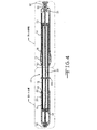
図1、1A、2−3、3A、3B、4、4A、及び4Bは、本発明の或る実施形態による、哺乳類の体内から細胞標本を採取するための装置10を示している。この実施形態では、装置10は、基端14と先端16を有する内側ハンドル部材12を備えている。第1外側ハンドル部材18は、内側ハンドル部材12の基端14上に滑動可能に配置されている。第2外側ハンドル部材20は、内側ハンドル部材の先端16上に滑動可能に配置されている。内側ハンドル部材12には、細長いシース22が取り付けられ、軸方向に内側ハンドル部材12の先端16を越えて伸長している。ここで使用している「軸線方向」という用語は、或る部材が別の部材の或る軸線の周りに、或る軸線の方向に、或る軸線上に、又は或る軸線に沿って、配置されていることを指し、或る部材が別の部材の、中心軸線の周りに、中心軸線の方向に、中心軸線上に、又は中心軸線に沿って、配置されていることに限定されるものではない。シース22はシースルーメン24を画定している。
1, 1A, 2-3, 3A, 3B, 4, 4A, and 4B illustrate a
第1外側ハンドル部材18には針26が取り付けられており、この針は、少なくとも部分的にはシースルーメン24の中に配置されている。他の実施形態では、針の代わりに、概ね管状の末端部又は他の鋭利でない形状の末端部を有する第1部材が使用されている。針26は、吸引が行えるようになっている。針26は、鋼及び他の種類の金属を含む各種材料で作ることができる。針26は、針ルーメン28を画定しており、基端31と先端33を有している。針ルーメン28の中には、基端35と鋭利な先端37を有するスタイレット30が滑動可能に配置されているが、このスタイレットは、処置中の各時点で、全体が針ルーメン28の外側に出されたり、部分的に針ルーメン28の中に配置されたり、或いは全体が針ルーメン28の中に配置されたりするようになっている。他の実施形態では、スタイレットの先端は鋭利ではなく、丸みを帯びた形状など様々な形状を呈している。スタイレット30は、中実のロッドを備えている。スタイレット30が針ルーメン28に挿入されると、スタイレット30の外周39は針ルーメン28の内径41にぴったりと合う。スタイレット30の鋭い先端37は、哺乳類の体内の或る領域を切り取るために針の先端33を1センチメートル程度越えて伸ばせるようになっているので、スタイレット30を軸線方向に動かすことによって細胞標本を切り取ることができる。他の実施形態では、スタイレット30の先端37は、針の先端30から様々な長さだけ伸長させることができる。更に別の実施形態では、スタイレット30の先端37は、組織を切り取るために針の先端33を越えて伸ばせるようにはなっておらず、その唯一の目的は、切断処置時に針ルーメン28を塞ぐことである。上記実施形態では、哺乳類体内で或る領域を切り取るのに、針26又は技術的に既知の他の装置及び/又は方法を使用してもよい。
A
本発明の顕著な利点は、細胞標本を切り取る際に、望ましくない液体や物質が、針ルーメン28を針の先端33において汚染することがないという点である。これは、スタイレット30の外周39が針ルーメン28の内径41とぴったり合っているので、スタイレット30が針のルーメン28を塞いでいるためである。スタイレット30は、鋼、金属、及びニチノールの1つ又はそれ以上で作ることができる。他の実施形態では、スタイレットは、矩形及び多角形を含む様々な形状に、種々の材料で作ることができる。スタイレット30は、軸線方向に、第2外側ハンドル部材20を越えてシースルーメン24の中へと伸長している。後で説明するように、ハンドル49は、スタイレット30と針26を軸線方向に動かすようになっている。上記好適な実施形態の他にも、ハンドル49は、フィンガループ型ハンドル、ピン−バイス型ハンドル、及びハーフフィンガループ型ハンドルを含む様々な型式を含んでいてもよい。
A significant advantage of the present invention is that undesirable fluids and materials do not contaminate the
図1は、本発明のこの実施形態による装置10の閉じた状態を示している。即ち、第1及び第2外側ハンドル部材18、20は、内側ハンドル部材12のそれぞれの対応する部分の上に一杯に押し込まれている。この実施形態のこの状態では、第1及び第2外側ハンドル部材18、20は、内側ハンドル部材12を包み込んでいる。
FIG. 1 shows a closed state of the
図2は、開いた状態の装置10を示している。この状態では、第1及び第2外側ハンドル部材18、20は、共に、図1に示す内側ハンドル部材に対する各々の位置から後退している。この開いた状態では、内側ハンドル部材12が露出する。装置10を図1に示す閉状態から図2に示す開状態に変えると、各種構成要素の相対位置が変わる。例えば、シース22は内側ハンドル部材12に取り付けられているので、第2外側ハンドル部材20を内側ハンドル部材12に沿って動かすと、シース22の、第2外側ハンドル部材20の先端を越えて軸線方向に伸長する長さが、その分だけ変化する。また、針26は第1外側ハンドル部材18に取り付けられているので、第1外側ハンドル部材18を内側ハンドル部材12に沿って動かすと、シース22に対する針26の位置が変わる。何がしかのこの移動によって、針26の、シース22の先端を越えて軸線方向に伸長する長さが変わる。図1と図2を比較すると、装置10が閉状態(図1)にあるときには、針26はシース22の先端を越えて軸線方向に伸長することができるが、ハンドルが開状態(図2)にあるときには、完全にシース22の中に納まることができる。
FIG. 2 shows the
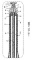
図3と図4は、それぞれ閉状態と開状態にある装置10の断面図である。図3A、3B、4A、4Bに示す拡大図を含め、これらの図面は、装置10を使って様々な構成要素の相対位置を制御するための様々な機構を示している。
3 and 4 are cross-sectional views of the
内側ハンドル部材12は、装置10の様々な構成要素の様々な部分が入っているハンドルルーメン32を画定している。先端側キャップ34は、ハンドルルーメン32を内側ハンドル部材12の先端16で閉じている。先端側キャップ34は、内側ハンドル部材12と一体でもよいし、別個に取り付ける部材でもよい。先端側キャップ34は、第1及び第2先端側キャップストッパ36、38を画定している。これらのストッパ36、38は、内側ハンドル部材12によって画定される第1及び第2先端側案内溝40、42の端部に配置されている。第2外側ハンドル部材20は、第1及び第2突起部46、48を画定している先端側カラー44を有している。第2外側ハンドル部材20を内側ハンドル部材12に沿って滑動させると、これらの突起部46、48は、それぞれ第1及び第2先端側案内溝40、42に沿って動く。最終的には、先端側キャップストッパ36、38は、突起部46、48に当接し、第2外側ハンドル部材20がそれ以上先端方向に動くのを妨げる。先端側キャップ34の場合と同様に、先端側カラー44は、第2外側ハンドル部材20と一体の構成要素でもよいし、別個に取り付けられる部材でもよい。また、内側ハンドル部材12は、先端側案内溝の数がこれより少なくても多くてもよく、装置10は、第2外側ハンドル部材20の内側ハンドル部材12に沿う動きを制限するための機構として適した、代わりのどの様な機構を含んでいてもよい。
基端側キャップ50は、ハンドルルーメン32を内側ハンドル部材12の基端14で閉じる。基端側キャップ50は、第1及び第2基端側キャップストッパ52、54を画定している。これらのストッパ52、54は、内側ハンドル部材12によって画定される第1及び第2基端側案内溝56、58の端部に位置している。第1外側ハンドル部材18は、第1及び第2突起部62、64を画定している基端側カラー60を有している。第1外側ハンドル部材18を内側ハンドル部材12に沿って滑動させると、これらの突起部62、64は、それぞれ第1及び第2基端側案内溝56、58に沿って動く。最終的には、基端側キャップストッパ52、54は、突起部62、64に当接して、第1外側ハンドル部材18がそれ以上基端方向に動くのを妨げる。先端側キャップ34とカラー44の場合と同様に、基端側キャップ50とカラー60は、それぞれ内側ハンドル部材12及び第1外側ハンドル部材18と一体の構成要素でもよいし、別個の部材としてそれら構成要素に取り付けてもよい。また、内側ハンドル部材12は、基端側案内溝の数がこれより少なくても多くてもよく、装置10は、一般的に、第1外側ハンドル部材18の内側ハンドル部材12に沿う動きを制限するための機構として適した、代わりのどの様な機構を含んでいてもよい。
The
内側ハンドル部材12は、第1外側ハンドル部材18と第2外側ハンドル部材20の間にもストッパ66を有することができる。ストッパ66は、内側ハンドル部材12に沿って第1及び第2外側ハンドル部材18、20が動くことのできる領域を分離している。またストッパ66は、外側ハンドル部材18、20が内側ハンドル部材12に沿ってそれ以上動かないようにする物理的障壁を提供している。ストッパ66を設ける場合には、ストッパ66は、内側ハンドル部材12と一体の部分でもよいし、別個に取り付けられる部材でもよい。図2を見ると良く分かるように、このストッパ66は、内側ハンドル部材12によって画定された円周方向の突起部から成ることができる。
The
装置10は、更に、装置10を操作し易くする様々な適応構造を有していてもよい。例えば、図2を見ると良く分かるように、内側ハンドル部材21には、第1のシリーズ68の目盛70を配置することができる。このシリーズ68の目盛は、設けるのであれば、内側ハンドル部材12の、第1外側ハンドル部材18を沿わせて動かす部分の上に配置することができる。このように構成すると、そのシリーズ68の各目盛70は、第1外側ハンドル部材18に取り付けられている針26の、内側ハンドル部材12に取り付けられているシース22の先端に対する所定の位置に対応させることができる。更に、このシリーズ68の各目盛70は、針26がシース22の先端を超えて軸線方向に伸張する所定の長さに対応させることができる。
The
図1と2を更に比較すると、このシリーズ68の目盛70の操作例が説明される。図2に示す開状態では、シリーズ68の目盛70で見ることのできる最も基端側の目盛は「0」である。またこの状態では、針26は、シース22の先端を超えて伸長しない。従って、この例では、目盛「0」は、シース22の先端を超えて軸線方向に伸長する針26の長さがゼロであることに対応している。図1では、ハンドルは、完全に閉状態にある。図2に示す開状態からこの状態にするには、ユーザーは、第1外側ハンドル部材18を、シリーズ68の目盛70の全てを覆うように進ませることになる。ユーザーが第1外側ハンドル部材18を内側ハンドル部材12に沿って動かすと、第1外側ハンドル部材18は、シリーズ68の目盛70を連続的に通過する。各目盛70は、針26がシース22の先端を超えて伸長する長さに対応することができる。第1外側ハンドル部材18が内側ハンドル部材12を覆うように一杯に進んで、ストッパ66に達すると、シリーズ68の目盛70が全て覆われる。図1に示すように、この状態は、針26がシース22の先端を超えて伸長する最大長さに対応している。従って、カラー60のような第1外側ハンドル部材18の先端をシリーズ68の目盛70の特定の目盛まで動かすことによって、装置10のユーザーは、針26を、シース22に対して所望の位置に進めることができる。
Further comparison of FIGS. 1 and 2 illustrates an example of the operation of the
装置10は、更に、第2のシリーズ72の目盛74を有することができる。第1のシリーズ68の目盛70と同様に、第2のシリーズ72の目盛74は、内側ハンドル部材12の上に配置することができる。第2のシリーズ72の目盛74は、内側ハンドル部材12の、第2外側ハンドル部材20を沿わせて動かす部分の上に配置することができる。このように構成すると、第2のシリーズ72の目盛74の各目盛は、内側ハンドル部材12に取り付けられているシース22が、別の医療装置に取り付けることのできる第2外側ハンドル部材20の先端を超えて軸方向に伸長する所定の長さに対応する。
The
図1と図2を更に比較すると、このシリーズ72の目盛74の操作例が説明される。図2に示す開状態では、シリーズ72の目盛74で見ることができる最も基端側の目盛は「0」である。目盛「0」は、シース22が第2外側ハンドル部材20の先端を超えて伸長する特定の長さに対応させることができる。第2外側ハンドル部材20を、従って装置10全体を、内視鏡のような作業ルーメンを有する別の医療装置と共に用いる場合、目盛「0」は、別の医療装置の先端を超えて軸方向に伸張するシース22の長さがゼロであることに対応することができる。例えば、「0」目盛は、シース22が、取り付けられた医療装置の作業ルーメンから外に全く伸張していないことを示してもよい。第2外側ハンドル部材20を内側ハンドル部材12に沿って動かすと、シリーズ72の連続する目盛74を通過する。シリーズ72の各目盛74は、シース22が第2外側ハンドル部材20の先端を超えて伸長する所定の長さに対応させることができる。更に、第2外側ハンドル部材20を別の医療装置と共に用いる場合、各目盛74は、シースが医療装置の先端を超えて軸線方向に伸長する所定の長さに対応させることができる。第2外側ハンドル部材20が内側ハンドル部材12を覆うように一杯に進められて、ストッパ66に達し、図1に示す閉状態になると、シリーズ72の目盛74は全て覆われ、これは、シース22が第2外側ハンドル部材20の先端又は取り付けられている医療装置の先端を超えて軸線方向に伸長する最大長さを示すことができる。
Further comparison between FIG. 1 and FIG. 2 will explain an operation example of the
第1外側ハンドル部材18は、装置10を操作し易くする適応構造を有していてもよい。例えば、第1外側ハンドル部材18は、ユーザーの指又は親指に休止位置を提供する拡径部76を画定することができる。拡径部76は、第1外側ハンドル部材18の外周部分であり、第1外側ハンドル部材18の他の部分より直径が大きくなっている。更に、グリップ挿入部78は、第1外側ハンドル部材18に取り付けられているか、又は第1外側ハンドル部材18で画定されていてもよい。グリップ挿入部78は、装置10を取扱い易くする表面を提供している。グリップ挿入部78は、プラスチックのような、第1外側ハンドル部材18と同じ材料で形成してもよいし、ゴム又は他のポリマー材料のような別の材料でもよい。
The first
装置10は、他の医療装置と共に使用することができる。実施形態の中には、装置10を別の医療装置に取り付けることができるようにした方が望ましいものもある。第2外側ハンドル部材20は、装置10を別の医療装置へ取り付け易くする適応構造を画定している。例えば、第2外側ハンドル部材20は、コネクタ80を画定することができる。コネクタ80は、装置10を取り付けようとする他の医療装置の別のコネクタと構造的に相互作用することができる。コネクタ80と医療装置の別のコネクタの間のこの相互作用は、嵌合接続でも係止接続でもよい。適切であればどの様なコネクタをコネクタ80として使用してもよく、ルアー型コネクタは、特に適しているコネクタの例である。他の適切な型式のコネクタには、クランプコネクタ、つまみねじのような係合部材接続、などがある。
The
装置10は、装置の内側構成要素同士を相対的に動かし易くする追加構成要素を含んでいてもよい。そのような追加構成要素の例を、図3A、3B、4A、4Bに示している。内側ガイド管82を、ハンドルルーメン32内の、針26の回りに配置することができる。内側ガイド管82は、針26を取り囲む管状部材である。内側ガイド管82は、内側ハンドル部材12のストッパ66近くに配置されているカラー84を画定することができる。内側ガイド管82は、内側ハンドル部材12に取り付けることもできる。更に、図3Aで良く分かるように、内側ハンドル部材12の位置は、針26を取り囲むか、カラー84をストッパ66に隣接して配置するか、又はその両方によって固定することができる。図3Bで良く分かるように、外側ガイド管86も、ハンドルルーメン82内の、内側ガイド管82の一部の回りに配置することができる。この実施形態では、外側ガイド管82は、第1外側ハンドル部材18に取り付けられており、従って、第1外側ハンドル部材18を内側ハンドル部材12に沿って滑動させると、内側ガイド管82に沿って滑動する。外側ガイド管86を第1外側ハンドル部材18へ取り付けるのは、適していればどの様な方法で行ってもよい。この実施形態では、外側ガイド管86は、基端にフレア88を画定している。フレア88は、第1外側ハンドル部材18のくぼみ90に配置されている。アクセスポート92は、第1外側ハンドル部材18の基端に、フレア88に隣接して配置され、外側ガイド管86を、第1外側ハンドル部材18に対して所定の位置に効果的に係止している。この取り付けは、接着剤、又は他の適切な結合機構で行ってもよい。
内側ガイド管82と外側ガイド管86を設けると、装置10を開状態と閉状態の間で繰り返し動かす間にハンドルルーメン32内の構成要素が座屈するのを防ぐことができる。
Providing the
アクセスポート92は、装置10の外部環境から針ルーメン28へのアクセスを提供する。アクセスポート92は、第1外側ハンドル部材18と一体に形成してもよいし、別に取り付ける部材でもよい。
スタイレット30は、アクセスポート92の中に滑動可能に配置されている。スタイレット30は、第1外側ハンドル部材18の基端にキャップ96を含んでおり、このキャップは、スタイレットの基端35に取り付けられ、アクセスポート92に対する挿入及び取り外しをやり易くする。キャップ96は、アクセスポート92によって画定されている喉部94と相互作用して、スタイレット30のアクセスポート92内への動きを案内し、及び/又は制限することができる。更に、キャップ96は、キャップ96のアクセスポート92に対する位置を固定する適応構造を画定してもよい。例えば、キャップ96は、アクセスポート92が画定する溝100に入り込むノッチ98を画定してもよい。ノッチ98と溝100の間のこの相互作用によって、キャップ96と取り付けられたスタイレット30の回転及び軸方向運動が防止される。
The
図5と図6は、本発明の別の実施形態によるハンドル110を示している。この実施形態のハンドル110は、以下に詳細に述べること以外は、先に述べた実施形態のハンドルと同じである。従って、図5と図6の同じ参照番号は、先に述べ図1−3、3A、3B、4、4A、4Bに示している実施形態の同じ機構及び/又は構成要素を指す。図5は、この実施形態によるハンドル110の閉じた状態を示している。
5 and 6 illustrate a
この実施形態では、第2外側ハンドル部材120は、孔111を画定している。孔111は、内側ハンドル部材12の上に配置されている一連の目盛174の部分の上に配置されるように、第2外側ハンドル部材120に配置されている。孔111の寸法形状は様々であってもよいが、孔111は、1つ又は複数の目盛174を有意な方法で示すことができるようになっていなければならない。
In this embodiment, the second
この実施形態では、第2外側ハンドル部材120は、更に、内側ハンドル部材112の第2外側ハンドル部材120に対する軸方向位置を固定するための手段を含んでいる。2つの滑動可能に係合されている構成要素の間の軸方向位置を固定するのに適していれば、どの様な手段を使用してもよい。例えば、第2外側ハンドル部材120の厚さを貫通して伸長する選択的に係合可能な部材を、固定するための手段として使用することができる。選択的に係合可能な部材は、壁厚から引き抜き、又は壁厚を貫通して進め、内側ハンドル部材112と係合させることができる。壁厚を貫通させ内側ハンドル部材112と接触させて配置すると、第2外側ハンドル部材120に対する内側ハンドル部材112の軸方向位置が固定される。即ち、内側ハンドル部材112と選択的に係合可能な部材が接触しているので、第2外側ハンドル部材120が、内側ハンドル部材112に沿ってそれ以上軸方向に動くのが妨げられる。
In this embodiment, the second
図5は、固定するための手段として使用するのに適した選択的に係合可能な部材であるつまみねじ113を示している。つまみねじ113は、第2外側ハンドル部材120の壁厚を貫通して容易に進ませ、内側ハンドル部材112と接触させ、内側ハンドル部材112と第2外側ハンドル部材120の間の相対的な軸方向位置を固定することができる。第2外側ハンドル部材120には、つまみねじ113の相補形のねじ山と相互作用するねじ山が設けられており、つまみねじ113が、第2外側ハンドル部材120の壁厚を出入りできるようにしている。
FIG. 5 shows a
この実施形態では、更に、滑動可能部材115が、内側ハンドル部材112上に配置されている。滑動可能部材115は、内側ハンドル部材112上に滑動可能に配置されている係止部材でもよい。滑動可能部材115は、滑動可能部材115を内側ハンドル部材112上の複数の位置の何れにでも係止できる適応構造を有していてもよい。例えば、滑動可能部材115は、第2外側ハンドル部材120に関して先に述べたように、つまみねじ119のような上記の固定するための手段を有していてもよい。滑動可能部材115は、内側ハンドル部材112に沿う第1外側ハンドル部材118の動きを制限する移動可能なストッパとなっている。従って、このストッパは、第1外側ハンドル部材118に取り付けられている針126の、シースに対する動きを制限する。滑動可能部材115を、目盛170で表示される、内側ハンドル部材112に沿う所望の位置に係止することによって、ハンドル110のユーザーは、針126がシース122を超えて伸長できる最大長さを設定することができる。この様にすれば、ユーザーは、第1外側ハンドル部材118を、内側ハンドル部材112の調整幅に沿って、一杯に引っ込んだ位置と滑動可能部材115が係止されている位置との間で動かすことができる。この調整幅は、第1外側ハンドル部材を沿わせて動かすことのできる内側ハンドル部材112の限られた部分であり、調整幅の正確な長さは、滑動可能部材115が係止される位置に依って決まる。言い換えると、滑動可能部材115の選択された位置は、シース122に対する針126の所望の最大伸張長さに依って決まる。
In this embodiment, a
滑動可能部材115を内側ハンドル部材112の所望の場所に位置決めし易くするために、滑動可能部材115は、下にある内側ハンドル部材112の1つ又は複数の目盛170を含む部分が見えるようにする孔117を画定してもよい。孔117の寸法、形状及び構成は、適していればどの様なものでもよいが、下にある内側ハンドル部材の部分が、少なくとも1つの目盛170が完全に見えるような、有意の様式で見えるようになっていなければならない。図5及び図6に示すように、滑動可能部材115は、内側ハンドル部材112の回りに円周状に、且つ第1外側ハンドル部材118と第2外側ハンドル部材120の間に、配置されているカラーを有していてもよい。
In order to facilitate positioning of the
図7及び図7Aは、本発明の別の実施形態によるハンドル210を示している。この実施形態によるハンドル210は、以下に詳細に説明すること以外は、先に述べた第1実施形態のハンドルと同じである。従って、図7及び図7Aの同じ参照番号は、先に述べ図1−3、3A、3B、4、4A、4Bに示した実施形態の同じ機構及び/又は構成要素を指す。図7は、この実施形態によるハンドルの開状態を示している。
7 and 7A illustrate a
この実施形態では、内側ハンドル部材212は、第1案内溝221と第2案内溝223を画定している。案内溝221、223の内の一方又は両方は、外側ハンドル部材218、220又は他の滑動可能に取り付けられた部材のような他の構成要素が配置される、ハンドル部材上の個々別々の位置を画定する複数のストッパ225を有している。この実施形態では、ストッパ225は、内側ハンドル部材212により画定され、案内溝221、223内に配置されている突起を備えている。ストッパ225は、案内溝221、223内に配置される別個に取り付けられる部材であってもよい。
In this embodiment, the
ストッパ225は、構成要素の、内側ハンドル部材212上の滑動運動を一時的に止めるが、そのような運動を完全に停止させるわけではない。そうではなく、ストッパ225は、単に抵抗を提供するものであり、追加して力を掛ければこの抵抗に打ち勝って、構成要素を、内側ハンドル部材212に沿って継続して滑動運動させることができる。滑動可能な構成要素を内側ハンドル部材112に沿って動かすと、滑動可能な構成要素は、ストッパ225と相互作用して音を発生することができる。このように音を生じさせると、ハンドル210のオペレーターに、ハンドル210の様々な構成要素の相対位置を示す、追加的なフィードバックを提供することができる。この様にストッパ225と相互作用する滑動可能な構成要素は、外側ハンドル部材218、220の内の一方又は両方でもよいし、図5及び図6に示した実施形態に関連して先に述べた滑動可能部材のような、内側ハンドル部材212上に配置されているどの様な他の滑動可能な構成要素でもよい。
The
ストッパ225は、適していればどの様な配列及び構成で、内側ハンドル部材212上に配置してもよい。図7で良く分かるように、ストッパ225は、内側ハンドル部材212上に配置されている一連の目盛268の各目盛270に隣接して配置してもよい。また、第1組のストッパ225を内側ハンドル部材212の或る部分に配置し、第2組のストッパ225を内側ハンドル部材212の第2部分に配置してもよい。例えば、図7に示しているように、第1組のストッパ225を、第1のシリーズ268の目盛270に隣接して配置し、第2組のストッパ225を、第2のシリーズ272の目盛274に隣接して配置してもよい。
The
この実施形態では、内側ハンドル部材は、適していればどの様な数の案内溝を画定してもよく、1つ又は複数の案内溝にストッパ225を設けることができる。
In this embodiment, the inner handle member may define any number of guide grooves where appropriate, and a
図8、8A、9−10、10A、10B、11、11A、11Bは、スタイレット30が針ルーメン28から引き抜かれ、ブラシ300が針ルーメン28内のその位置に挿入されている点以外は、図1、1A、2−3、3A、4、4A、4Bに示しこれまで説明してきた装置と同一である。ブラシ300は、スタイレット30で切り取られた細胞標本を採取するのに使用される細胞採取装置である。他の実施形態では、膨張可能バルーン、ワイヤメッシュ装置、又は他の型式の採取装置のような異なる細胞採取装置を使用することもできる。針ルーメン28に挿入されると、ブラシ300は、処置中の様々な時機に、部分的に針ルーメン28の中に配置されたり、或いはその全体が針ルーメン28内に配置されたりすることができる。ブラシ300は、基端312と先端318を有する細長い部材324と、この細長い部材306の先端318の付近の箇所330に取り付けられた複数の剛毛324とを備えている。細長い部材306は、ワイヤ336を備えている。ワイヤ336は、鋼、その他の種類の金属、及びニチノールを含む各種材料で作ることができる。複数の剛毛324を取り巻くようにワイヤ336を撚り、複数の剛毛324をワイヤに結合している。剛毛324は、ナイロン、真鍮、鋼、カーボン、ポリマー、又はその他の種類の金属を含む各種材料で作ることができる。ブラシ300は、第2外側ハンドル部材20を越え、シースルーメン24の中へと、軸線方向に伸びている。細長い部材306の先端318は、鋼キャップ342で終端している。他の実施形態では、細長い部材306は、ループ、ボールチップ、円錐チップ、傘形チップ、又は他の型式の先端チップで終端し、この先端チップは、様々な種類の金属及び鑞を含む各種材料で作ることができる。以上論じたように、ハンドル49は、ブラシ300と針26を軸線方向に動かせるようになっている。上記の好適な実施例の他にも、ハンドル49は、フィンガループ型ハンドル、ピン−バイス型ハンドル、及びハーフフィンガループ型ハンドルを含むさまざまな型式を有していてもよい。
8, 8A, 9-10, 10A, 10B, 11, 11A, 11B, except that the
ブラシ300は、アクセスポート92の中に滑動可能に配置される。ブラシ300は、スタイレット30と同じように、第1外側ハンドル部材18の基端にキャップ304を有しており、このキャップは、細長い部材306に取り付けられ、アクセスポート92に挿入したり、それから取り外したりし易くする。キャップ304は、アクセスポート92によって画定されている喉部94と相互作用して、ブラシ300のアクセスポート92内への運動を案内及び/又は制限する。更に、キャップ304は、キャップ304のアクセスポート92に対する位置を固定する適合構造を画定することができる。例えば、キャップ304は、アクセスポート92によって画定されている溝100に入り込むノッチ98を画定することができる。ノッチ98と溝100の間のこの相互作用によって、キャップ304と取り付けられているブラシ300の回転運動を防止することができる。
The
最初に、ブラシの遠位端318を針の内側ルーメン28の中に配置する。次いで、ブラシの先端318を針の内側ルーメン28の外側に伸ばすために、キャップ304をハンドル49に向けて軸線方向に伸ばす。一旦、ブラシの先端318が針の内側ルーメン28の外まで伸びたら、ブラシの先端318付近の剛毛324を使用して細胞標本を採取するために、キャップ304を軸線方向に前後に動かす。細胞標本が採取されたら、ブラシの先端318を針の内側ルーメン28の中に後退させて、標本を体から取り出す際に望ましくない液体や物質によって標本が汚染されるのを防止するため、キャップ304を、軸方向にハンドル49から離れる方向に後退させる。キャップ304は、針の先端33に当接して、標本が汚染されるのを防ぐことができる。ブラシ300の先端318又は他の細胞採取装置が針の先端33を越えて伸び出した時を操作者に示すため、ブラシ300の基端312付近にマーク又はマーカーを使用してもよい。
Initially, the
図12、12A、12B、12Cは、上記実施形態のブラシ300が、スタイレット30で切り取られた細胞標本を採取するのに使用される細胞採取装置として働く、膨張可能且つ収縮可能なバルーンに置き換えられている別の実施形態を示している。バルーン350は、内側ルーメン352を有する管351に接続されており、この内側ルーメンを通して空気又は液体を導入して、バルーン350を満たすことができるようになっている。管351とバルーン350のアッセンブリは、内側ハンドル12を通ってシースルーメン24に入り、更に針26の内側ルーメン28へと伸びている。管を定位置に係止する位置まで、管351の端部のキャップ354をねじ込む。バルーン350は、収縮した状態では針26の内側ルーメン28の中にちょうど収まり、針28の内側ルーメンの外側にあるときには哺乳類の体内で細胞標本を採取するために膨らむようになっている。図12Bは、バルーン350と管351のアッセンブリの、バルーン350が収縮した状態を示している。図12Cは、バルーン350と管351のアッセンブリの、バルーン350が膨らんだ状態を示している。膨らんだ状態のときに細胞標本を採取するため細胞組織をこすり取ることができるように、バルーン350の外面356は、ざらざらになっている。バルーンは、ポリエチレンテレフタレートである。第1外側ハンドル部材18の基端には、キャップ354が滑動可能に配置され、バルーン350の軸線方向の動きを制御するため、バルーン350と管351のアッセンブリに取り付けられている。バルーン350の軸線方向の動きを制御するのにキャップ354を使用し、バルーン350は、最初は収縮した状態で針26の内側ルーメン28の中に入っており、細胞標本を得るために、針26の内側ルーメン28から滑り出させて膨らませ、細胞標本を得た後は、針26の内側ルーメン28の中に引き戻される。
FIGS. 12, 12A, 12B, 12C replace the
図13は、本発明の別の実施形態による医療器具アッセンブリ352を示している。この医療器具アッセンブリ352は、本発明の実施形態の何れかによるハンドル356を備えている。ハンドル356は、医療器具375に取り付けられている。医療器具375は、作業ルーメン377を画定している。ハンドル356のシース366は、ハンドル356の内側ハンドル部材に取り付けられており、軸線方向に、内側ハンドル部材の先端を越えて医療器具375の作業ルーメン377の中へと伸長している。医療器具375に対するハンドル356の取り付けは、上記のような第2外側ハンドル部材360側にコネクタを配置することを含め、適していればどの様なやり方で行ってもよい。
FIG. 13 illustrates a
本発明による医療器具アッセンブリ352に使用するのに適した医療器具375は、内視鏡を備えている。上記の実施形態の何れにも、一連の波動又はパルスを発するトランスデューサ380を内蔵した内視鏡が含まれる。波動又はパルスは、哺乳類体内の体組織を通って、組織の物理的特性によって決まる速度で伝播する。次いで、波動又はパルスは、音波が通過しにくい組織又は他の塊に遭遇すると、反射されてトランスデューサに戻る。トランスデューサ380は、反射された波動を検知して、波動が反射された組織又は他の塊の位置を測定するために、画像処理用の電気信号に変換する。このようにして、トランスデューサ380は、バルーン又はブラシのような細胞採取装置の体内での位置を測定することができる。或る実施形態では、超音波を反射し易くするため、細胞採取装置は、基端と先端を有する窪み付きワイヤと、この窪み付きワイヤの先端付近の箇所に接続された複数の剛毛とを備えていてもよい。窪み付きワイヤは、超音波の反射を支援する。別の実施形態では、剛毛は、鋼、又は超音波を反射し易くする他の材料であってもよい。この装置と方法を使用すれば、操作者又は医師は、処置中に体内で細胞採取装置を誘導し易くなる。
A
上に開示した実施形態の何れを使用しても、哺乳類の体から細胞標本を採取するのに、数多くの方法を採用することができる。図14−14Dは、図1−4B及び図8−11Bの装置を使用するこの様な1つの方法の各段階を開示している。図14に示すように、スタイレット30は、針26の内側ルーメン28に、その鋭利な先端37が針26の先端33を越えて伸張する状態に挿入される。スタイレット30は、標本切り取りの間の汚染を回避するため、針26の内側ルーメン28を塞ぐ。そして、スタイレット30の鋭利な先端37を、スタイレット30の基端35に取り付けられたキャップ96を軸線方向に前後に動かすことにより使用して、嚢胞の様な哺乳類体内の或る領域を切り取る。他の実施形態及び/又は方法では、スタイレット30の先端37は、鋭利ではなく、切断には使えないようにして、切断処置時に針26の内側ルーメン28を塞ぐことに目的を限ってもよい。これらの実施形態では、哺乳類体内の或る領域を切り取るために、針26又は技術的には既知の他の装置及び/又は方法が使用される。次に、図14Aに示すように、スタイレット30を、針26の内側ルーメン28から引き出す。この時点で、針26を通して吸引を行うこともできる。次いで、図14Bに示すように、細胞採取装置300を針26の内側ルーメン28に挿入する。他の実施形態では、装置は、体内の細胞採取装置の位置を測定するために使用される、超音波を発するトランスデューサを備えた内視鏡を含んでいる。次に、図14Cに示すように、細胞採取装置300の先端318を、細胞採取装置300が針26の先端33を越えて伸長するまで、伸ばす。次に、細胞採取装置300を使用し、細胞採取装置300の近位端312に取り付けられたキャップ304を軸線方向に前後に動かしながら、細胞標本を採取する。最後に、図14Dに示すように、採取した標本の汚染を回避するため、細胞採取装置300の先端318を針26の内側ルーメン28の中に後退させる。次いで装置を体内から取り出す。
A number of methods can be employed to collect cell specimens from the mammalian body using any of the embodiments disclosed above. FIGS. 14-14D disclose the steps of one such method using the apparatus of FIGS. 1-4B and FIGS. 8-11B. As shown in FIG. 14, the
図15は、哺乳類の体から細胞標本を採取するための別の方法をフローチャート形式で示している。先ず、ステップ400で装置を用意する。装置は、作業ルーメンを画定し且つトランスデューサを含んでいる内視鏡を備えている。加えて、装置は、基端と、先端と、内側ルーメンを含んだ第1部材を備えており、この第1部材は、内視鏡の作業ルーメンの中へと伸長している。第1部材は針であるのが望ましい。また、装置は、基端と細胞採取用の先端とを有する細胞採取装置を含んでおり、この細胞採取装置は、第1部材の内側ルーメンの中へと伸長している。内視鏡の作業ルーメンは、ステップ410で哺乳類体内に挿入される。次に、ステップ420で、細胞採取装置の先端を、第1部材の先端を越えるように伸長させる。ステップ430で、内視鏡のトランスデューサから超音波を放射する。ステップ440で、この超音波は、細胞採取装置に、その材料と組成のために反射され、ステップ450で、内視鏡のトランスデューサで受信される。トランスデューサは、画像形成のために、この波動を電子信号に変換する。最後に、ステップ460で、トランスデューサが受信した超音波から形成された変換画像により、哺乳類体内の細胞採取装置の位置が測定される。
FIG. 15 illustrates, in flowchart form, another method for obtaining a cell sample from a mammalian body. First, in
以上の詳細な説明は、本発明の代表的な実施形態を提供しており、本発明を実施するのに最適な形態を含んでいる。これらの実施形態は、本発明の例となることだけを意図しており、如何なる意味でも本発明の範囲を制限するものではない。 The foregoing detailed description provides representative embodiments of the invention and includes the best mode for carrying out the invention. These embodiments are only intended to be examples of the invention and are not intended to limit the scope of the invention in any way.
Claims (107)
基端と、先端と、該基端から該先端まで伸長している内側ルーメンと、を有する針と;
基端と先端を有するスタイレットであって、該スタイレットは、該針の該内側ルーメンに対して挿入されたり引き抜かれたりするようになっており、該スタイレットの少なくとも一部は、細胞標本が切り取られるとき、該針の該内側ルーメンを塞ぐように作られているスタイレットと;
基端と先端を有する細胞採取装置であって、該スタイレットが該針の該内側ルーメンから引き抜かれたときに、該針の該内側ルーメンに挿入されるようになされ、該細胞採取装置の該先端は、該細胞標本を採取するために該針の該先端を越えて伸長するように作られている細胞採取装置と、を備えている医療器具。 In medical equipment:
A needle having a proximal end, a distal end, and an inner lumen extending from the proximal end to the distal end;
A stylet having a proximal end and a distal end, wherein the stylet is adapted to be inserted into and withdrawn from the inner lumen of the needle, wherein at least a portion of the stylet is a cell sample A stylet that is configured to occlude the inner lumen of the needle when it is cut;
A cell collection device having a proximal end and a distal end, wherein the stylet is inserted into the inner lumen of the needle when the stylet is withdrawn from the inner lumen of the needle; A medical device comprising: a tip, a cell collection device configured to extend beyond the tip of the needle to collect the cell sample.
基端と先端を有する内側ハンドル部材と;
該内側ハンドル部材の上に滑動可能に配置された第1外側ハンドル部材と;
該内側ハンドル部材に取り付けられ、該内側ハンドル部材の該先端を超えて軸線方向に伸長している細長いシースであって、シースルーメンを画定しており、該針は、該第1外側ハンドル部材に取り付けられ、該シースルーメンの中に配置されている、細長いシースと、を備えている、請求項11に記載の医療器具。 The handle
An inner handle member having a proximal end and a distal end;
A first outer handle member slidably disposed on the inner handle member;
An elongate sheath attached to the inner handle member and extending axially beyond the tip of the inner handle member, defining a see-through membrane, the needle being attached to the first outer handle member The medical device of claim 11, comprising an elongate sheath attached and disposed within the see-through membrane.
基端と先端を有し、ハンドルルーメンを画定している内側ハンドル部材と;
該内側ハンドル部材の該基端の上に滑動可能に配置された第1外側ハンドル部材と;
該内側ハンドル部材の該先端の上に滑動可能に配置された第2外側ハンドル部材と;
該内側ハンドル部材に取り付けられ、該内側ハンドル部材の該先端を超えて軸方向に伸長している細長いシースであって、シースルーメンを画定しており、該針は、該第1外側ハンドル部材に取り付けられ、該ハンドルルーメンを通って該シースルーメンの中へと伸長している、細長いシースと;
該第1外側ハンドル部材の該基端に滑動可能に配置され、該細胞採取装置に接続されているキャップと、を備えている、請求項11に記載の医療器具。 The handle
An inner handle member having a proximal end and a distal end and defining a handle lumen;
A first outer handle member slidably disposed on the proximal end of the inner handle member;
A second outer handle member slidably disposed on the tip of the inner handle member;
An elongate sheath attached to the inner handle member and extending axially beyond the tip of the inner handle member, defining a see-through membrane, the needle being attached to the first outer handle member An elongated sheath attached and extending through the handle lumen and into the see-through lumen;
The medical device according to claim 11, comprising a cap slidably disposed at the proximal end of the first outer handle member and connected to the cell collection device.
トランスデューサを内蔵し、作業ルーメンを画定している内視鏡と、
基端と、先端と、内側ルーメンとを有し、該内視鏡の該作業ルーメンの中へと伸長している部材と、
基端と、細胞採取用の先端とを有する細胞採取装置であって、該部材の該内側ルーメンの中に挿入されるようになっており、該細胞採取装置の該先端は、該細胞標本を採取するために該部材の該先端を越えて伸長するようになっている細胞採取装置と、を備えており、
該トランスデューサは、超音波を発し、該超音波を使用して該哺乳類体内での該細胞採取装置の位置を測定する、医療器具。 In a medical device for collecting cell specimens from the mammalian body,
An endoscope containing a transducer and defining a working lumen;
A member having a proximal end, a distal end, and an inner lumen and extending into the working lumen of the endoscope;
A cell collection device having a proximal end and a cell collection tip, wherein the cell collection device is inserted into the inner lumen of the member; A cell collection device adapted to extend beyond the tip of the member for collection;
The transducer emits ultrasound and uses the ultrasound to measure the position of the cell collection device within the mammal.
基端と先端を有する内側ハンドル部材と;
該内側ハンドル部材の上に滑動可能に配置された第1外側ハンドル部材と;
該内側ハンドル部材に取り付けられ、該内側ハンドル部材の該先端を超えて軸線方向に伸長している細長いシースであって、シースルーメンを画定しており、該部材は、該第1外側ハンドル部材に取り付けられ、該シースルーメンの中に配置されている、請求項44に記載の医療器具。 The handle is:
An inner handle member having a proximal end and a distal end;
A first outer handle member slidably disposed on the inner handle member;
An elongate sheath attached to the inner handle member and extending axially beyond the tip of the inner handle member, defining a see-through membrane, the member being attached to the first outer handle member 45. The medical device of claim 44, attached and disposed within the see-through membrane.
基端と先端を有し、ハンドルルーメンを画定している内側ハンドル部材と;
該内側ハンドル部材の該基端の上に滑動可能に配置された第1外側ハンドル部材と;
該内側ハンドル部材の該先端の上に滑動可能に配置された第2外側ハンドル部材と;
該内側ハンドル部材に取り付けられ、該内側ハンドル部材の該先端を超えて軸線方向に伸長している細長いシースであって、シースルーメンを画定しており、該部材は、該第1外側ハンドル部材に取り付けられ、該ハンドルルーメンを通って該シースルーメンの中へと伸長している、細長いシースと;
該第1外側ハンドル部材の該基端に滑動可能に配置され、該細胞採取装置に接続されているキャップと、を備えている、請求項44に記載の医療器具。 The handle is:
An inner handle member having a proximal end and a distal end and defining a handle lumen;
A first outer handle member slidably disposed on the proximal end of the inner handle member;
A second outer handle member slidably disposed on the tip of the inner handle member;
An elongate sheath attached to the inner handle member and extending axially beyond the tip of the inner handle member, defining a see-through membrane, the member being attached to the first outer handle member An elongated sheath attached and extending through the handle lumen and into the see-through lumen;
45. The medical device of claim 44, comprising a cap slidably disposed at the proximal end of the first outer handle member and connected to the cell collection device.
基端と、先端と、該基端から該先端まで伸長している内側ルーメンとを有する針と;基端と先端とを有するスタイレットと;基端と細胞採取用の先端とを有する細胞採取装置と、を備えている装置を用意する段階と;
該スタイレットを該針の該内側ルーメンの中に挿入する段階であって、該スタイレットの少なくとも一部が該針の該内ルーメンを塞ぐ、挿入する段階と;
該哺乳類の体内で或る領域を切り取る段階と;
該針の該内側ルーメンから該スタイレットを引き抜く段階と;
該細胞採取装置を該針の該内側ルーメン内に、該細胞採取装置の該先端が該針の該先端を越えて伸長するように挿入する段階と;
該細胞採取装置を使用して、該哺乳類の体内から該細胞標本を採取する段階と;
該細胞採取装置の該先端を該針の該内側ルーメンの中に引き込む段階と、から成る方法。 In a method for collecting a cell sample from a mammalian body:
A needle having a proximal end, a distal end, and an inner lumen extending from the proximal end to the distal end; a stylet having a proximal end and a distal end; and a cell collection having a proximal end and a distal end for cell collection Providing a device comprising: a device;
Inserting the stylet into the inner lumen of the needle, wherein at least a portion of the stylet plugs and inserts the inner lumen of the needle;
Excising an area in the mammal's body;
Withdrawing the stylet from the inner lumen of the needle;
Inserting the cell harvesting device into the inner lumen of the needle such that the tip of the cell harvesting device extends beyond the tip of the needle;
Using the cell collection device to collect the cell sample from the mammalian body;
Retracting the tip of the cell harvesting device into the inner lumen of the needle.
基端と先端を有する内側ハンドル部材と;
該内側ハンドル部材の上に滑動可能に配置された第1外側ハンドル部材と;
該内側ハンドル部材に取り付けられ、該内側ハンドル部材の該先端を超えて軸線方向に伸長している細長いシースであって、シースルーメンを画定しており、該針は、該第1外側ハンドル部材に取り付けられ、該シースルーメンの中に配置されている、細長いシースと、を備えている、請求項62に記載の方法。 The handle is:
An inner handle member having a proximal end and a distal end;
A first outer handle member slidably disposed on the inner handle member;
An elongate sheath attached to the inner handle member and extending axially beyond the tip of the inner handle member, defining a see-through membrane, the needle being attached to the first outer handle member 63. A method according to claim 62, comprising an elongated sheath attached and disposed within the see-through membrane.
基端と先端を有し、ハンドルルーメンを画定している内側ハンドル部材と;
該内側ハンドル部材の該基端の上に滑動可能に配置された第1外側ハンドル部材と;
該内側ハンドル部材の該先端の上に滑動可能に配置された第2外側ハンドル部材と;
該内側ハンドル部材に取り付けられ、該内側ハンドル部材の該先端を超えて軸線方向に伸長している細長いシースであって、シースルーメンを画定しており、該針は、該第1外側ハンドル部材に取り付けられ、該針が該ハンドルルーメンを通って該シースルーメンの中へと伸長している、細長いシースと;
該第1外側ハンドル部材の該基端に滑動可能に配置され、該スタイレットに接続されているキャップと、を備えている、請求項62に記載の方法。 The handle is:
An inner handle member having a proximal end and a distal end and defining a handle lumen;
A first outer handle member slidably disposed on the proximal end of the inner handle member;
A second outer handle member slidably disposed on the tip of the inner handle member;
An elongate sheath attached to the inner handle member and extending axially beyond the tip of the inner handle member, defining a see-through membrane, the needle being attached to the first outer handle member An elongate sheath attached and wherein the needle extends through the handle lumen and into the see-through lumen;
63. A method according to claim 62, comprising a cap slidably disposed at the proximal end of the first outer handle member and connected to the stylet.
基端と先端を有し、ハンドルルーメンを画定している内側ハンドル部材と、
該内側ハンドル部材の該基端の上に滑動可能に配置された第1外側ハンドル部材と、
該内側ハンドル部材の該先端の上に滑動可能に配置された第2外側ハンドル部材と、
該内側ハンドル部材に取り付けられ、該内側ハンドル部材の該先端を超えて軸線方向に伸長している細長いシースであって、シースルーメンを画定しており、該針は、該第1外側ハンドル部材に取り付けられ、該ハンドルルーメンを通って該シースルーメンの中へと伸長している、細長いシースと、
該第1外側ハンドル部材の該基端に滑動可能に配置され、該細胞採取装置に接続されているキャップと、を備えている、請求項62に記載の方法。 The handle
An inner handle member having a proximal end and a distal end and defining a handle lumen;
A first outer handle member slidably disposed on the proximal end of the inner handle member;
A second outer handle member slidably disposed on the tip of the inner handle member;
An elongate sheath attached to the inner handle member and extending axially beyond the tip of the inner handle member, defining a see-through membrane, the needle being attached to the first outer handle member An elongated sheath attached and extending through the handle lumen and into the see-through lumen;
64. A method according to claim 62, comprising a cap slidably disposed at the proximal end of the first outer handle member and connected to the cell harvesting device.
作業ルーメンを画定し且つトランスデューサを内蔵している内視鏡と、基端と先端を有し、該内視鏡の該作業ルーメンの中へと伸長する部材と、基端と細胞採取用の先端とを有し、該部材の該内側ルーメンの中へと伸長する細胞採取装置と、を備えている装置を用意する段階と、
該内視鏡の該作業ルーメンを該哺乳類の体内に挿入する段階と、
該細胞採取装置の該先端部を、該部材の該先端を越えて伸長させる段階と、
該内視鏡の該トランスデューサから超音波を発する段階と、
該細胞採取装置に該超音波を反射させる段階と、
該反射した超音波を、該内視鏡の該トランスデューサを使って受け取る段階と、
該哺乳類体内での該細胞採取装置の位置を測定する段階と、から成る方法。 In a method for collecting a cell sample from a mammalian body,
An endoscope defining a working lumen and incorporating a transducer; a member having a proximal end and a distal end and extending into the working lumen of the endoscope; a proximal end and a cell collection distal end Providing a device comprising: a cell collection device extending into the inner lumen of the member; and
Inserting the working lumen of the endoscope into the body of the mammal;
Extending the tip of the cell collection device beyond the tip of the member;
Emitting ultrasound from the transducer of the endoscope;
Reflecting the ultrasound to the cell collection device;
Receiving the reflected ultrasound using the transducer of the endoscope;
Measuring the position of the cell collection device within the mammal.
基端と先端を有する内側ハンドル部材と;
該内側ハンドル部材の上に滑動可能に配置された第1外側ハンドル部材と;
該内側ハンドル部材に取り付けられ、該内側ハンドル部材の該先端を超えて軸線方向に伸長している細長いシースであって、シースルーメンを画定しており、該部材は、該第1外側ハンドル部材に取り付けられ、該シースルーメンの中に配置されている、細長いシースと、を備えている、請求項95に記載の方法。 The handle is:
An inner handle member having a proximal end and a distal end;
A first outer handle member slidably disposed on the inner handle member;
An elongate sheath attached to the inner handle member and extending axially beyond the tip of the inner handle member, defining a see-through membrane, the member being attached to the first outer handle member 96. A method according to claim 95, comprising an elongated sheath attached and disposed within the see-through membrane.
基端と先端を有し、ハンドルルーメンを画定している内側ハンドル部材と;
該内側ハンドル部材の該基端の上に滑動可能に配置された第1外側ハンドル部材と;
該内側ハンドル部材の該先端の上に滑動可能に配置された第2外側ハンドル部材と;
該内側ハンドル部材に取り付けられ、該内側ハンドル部材の該先端部を超えて軸方向に伸長している細長いシースであって、シースルーメンを画定しており、該部材は、該第1外側ハンドル部材に取り付けられ、該ハンドルルーメンを通って該シースルーメンの中へと伸長している、細長いシースと;
該第1外側ハンドル部材の該基端に滑動可能に配置され、該細胞採取装置に接続されているキャップと、を備えている、請求項95に記載の方法。 The handle is:
An inner handle member having a proximal end and a distal end and defining a handle lumen;
A first outer handle member slidably disposed on the proximal end of the inner handle member;
A second outer handle member slidably disposed on the tip of the inner handle member;
An elongate sheath attached to the inner handle member and extending axially beyond the distal end of the inner handle member, defining a see-through membrane, the member comprising the first outer handle member An elongate sheath attached to and extending through the handle lumen and into the see-through lumen;
96. A method according to claim 95, comprising a cap slidably disposed at the proximal end of the first outer handle member and connected to the cell harvesting device.
Applications Claiming Priority (2)
| Application Number | Priority Date | Filing Date | Title |
|---|---|---|---|
| US10/731,500 US20040260199A1 (en) | 2003-06-19 | 2003-12-09 | Cytology collection device |
| PCT/US2004/040221 WO2005060835A2 (en) | 2003-12-09 | 2004-12-02 | Cytology collection device |
Publications (2)
| Publication Number | Publication Date |
|---|---|
| JP2007513692A true JP2007513692A (en) | 2007-05-31 |
| JP2007513692A5 JP2007513692A5 (en) | 2008-01-24 |
Family
ID=34710412
Family Applications (1)
| Application Number | Title | Priority Date | Filing Date |
|---|---|---|---|
| JP2006543882A Pending JP2007513692A (en) | 2003-12-09 | 2004-12-02 | Cell collection device |
Country Status (4)
| Country | Link |
|---|---|
| US (1) | US20040260199A1 (en) |
| EP (1) | EP1694213A2 (en) |
| JP (1) | JP2007513692A (en) |
| WO (1) | WO2005060835A2 (en) |
Cited By (10)
| Publication number | Priority date | Publication date | Assignee | Title |
|---|---|---|---|---|
| JP2012504469A (en) * | 2008-10-01 | 2012-02-23 | ビーコン エンドスコピック コーポレーション | Needle biopsy device |
| JP2012509747A (en) * | 2008-11-26 | 2012-04-26 | ビーコン エンドスコピック コーポレーション | Needle biopsy device with integrated needle protection |
| JP2014522272A (en) * | 2011-05-26 | 2014-09-04 | エーディーエヌ インターナショナル,エルエルシー | Expandable device for tissue collection from airway digestive system body lumen |
| JP2015519925A (en) * | 2012-03-22 | 2015-07-16 | サーレハ,ラフィック | Surgical instrument for collecting deep tissue and / or cell samples |
| JP2015527904A (en) * | 2012-07-02 | 2015-09-24 | クック・メディカル・テクノロジーズ・リミテッド・ライアビリティ・カンパニーCook Medical Technologies Llc | Endoscope access device having a detachable handle |
| JP2015173692A (en) * | 2014-03-13 | 2015-10-05 | Hoya株式会社 | Attachment extraction equipment and attachment extraction device |
| US9332973B2 (en) | 2008-10-01 | 2016-05-10 | Covidien Lp | Needle biopsy device with exchangeable needle and integrated needle protection |
| US9782565B2 (en) | 2008-10-01 | 2017-10-10 | Covidien Lp | Endoscopic ultrasound-guided biliary access system |
| JP2018529403A (en) * | 2015-09-01 | 2018-10-11 | ボストン サイエンティフィック サイムド,インコーポレイテッドBoston Scientific Scimed,Inc. | Scope-mounted INOD handle |
| US11298113B2 (en) | 2008-10-01 | 2022-04-12 | Covidien Lp | Device for needle biopsy with integrated needle protection |
Families Citing this family (46)
| Publication number | Priority date | Publication date | Assignee | Title |
|---|---|---|---|---|
| US7555333B2 (en) | 2000-06-19 | 2009-06-30 | University Of Washington | Integrated optical scanning image acquisition and display |
| US7901348B2 (en) | 2003-12-12 | 2011-03-08 | University Of Washington | Catheterscope 3D guidance and interface system |
| US20050165329A1 (en) * | 2004-01-22 | 2005-07-28 | Reflux Corporation | Multiple biopsy collection device |
| US20050256426A1 (en) * | 2004-05-12 | 2005-11-17 | William Brugge | Apparatus and method for collecting tissue samples |
| US7530948B2 (en) | 2005-02-28 | 2009-05-12 | University Of Washington | Tethered capsule endoscope for Barrett's Esophagus screening |
| JP2009515596A (en) * | 2005-11-10 | 2009-04-16 | ジンマー,インコーポレイティド | Orthopedic delivery device and instrument to minimize invasion |
| US8537203B2 (en) | 2005-11-23 | 2013-09-17 | University Of Washington | Scanning beam with variable sequential framing using interrupted scanning resonance |
| JP2009528128A (en) | 2006-03-03 | 2009-08-06 | ユニヴァーシティ オブ ワシントン | Multi-clad optical fiber scanner |
| US8840566B2 (en) * | 2007-04-02 | 2014-09-23 | University Of Washington | Catheter with imaging capability acts as guidewire for cannula tools |
| WO2008137710A1 (en) | 2007-05-03 | 2008-11-13 | University Of Washington | High resolution optical coherence tomography based imaging for intraluminal and interstitial use implemented with a reduced form factor |
| US8795197B2 (en) | 2007-07-17 | 2014-08-05 | Histologics, LLC | Frictional trans-epithelial tissue disruption collection apparatus and method of inducing an immune response |
| US8652067B2 (en) | 2007-07-17 | 2014-02-18 | Histologics, LLC | Frictional trans-epithelial tissue disruption and collection apparatus and method of inducing and/or augmenting an immune response |
| US20110190662A1 (en) * | 2008-10-01 | 2011-08-04 | Beacon Endoscopic Corporation | Rapid exchange fna biopsy device with diagnostic and therapeutic capabilities |
| EP2424460B1 (en) * | 2009-04-30 | 2017-05-24 | Cook Medical Technologies LLC | System for fiducial deployment |
| US9072542B2 (en) * | 2009-12-18 | 2015-07-07 | Cook Medical Technologies Llc | System and method for fiducial deployment |
| EP2531112B1 (en) * | 2010-02-05 | 2017-11-22 | Boston Scientific Scimed, Inc. | Nesting endoscopic ultrasound guided biopsy device |
| WO2011115751A1 (en) * | 2010-03-16 | 2011-09-22 | Boston Scientific Scimed, Inc. | Ablation handle attachment |
| US9044213B1 (en) | 2010-03-26 | 2015-06-02 | Histologics, LLC | Frictional tissue sampling and collection method and device |
| EP2613708B1 (en) * | 2010-09-07 | 2017-08-16 | Boston Scientific Scimed, Inc. | Endoscopic ultrasound fine needle aspiration device |
| AU2014221219B2 (en) * | 2010-09-07 | 2015-10-29 | Boston Scientific Scimed, Inc. | Endoscopic ultrasound fine needle aspiration device |
| US8968213B2 (en) | 2010-10-19 | 2015-03-03 | United States Endoscopy Group, Inc. | Cytology brush apparatus with improvements |
| EP2667785A2 (en) * | 2011-01-27 | 2013-12-04 | Mayo Foundation for Medical Education and Research | Cytological sample acquisition device and method |
| US20130006144A1 (en) * | 2011-06-28 | 2013-01-03 | Michael Clancy | Biopsy needle with flexible length |
| WO2013003087A1 (en) * | 2011-06-28 | 2013-01-03 | Cook Medical Technologies Llc | Flexible biopsy needle |
| US8838208B2 (en) | 2011-06-28 | 2014-09-16 | Cook Medical Technologies Llc | Fiducial deployment needle system |
| JP5379249B2 (en) * | 2012-01-13 | 2013-12-25 | 富士フイルム株式会社 | Tissue collection device |
| WO2013116560A1 (en) * | 2012-01-31 | 2013-08-08 | The Trustees Of Columbia University In The City Of New York | Tissue sampling devices, methods, and systems |
| US9757099B2 (en) | 2012-02-27 | 2017-09-12 | Cook Medical Technologies Llc | Biopsy needle with enhanced flexibility |
| US20130267870A1 (en) * | 2012-04-06 | 2013-10-10 | Histologics Llc | Cell and tissue collection method and device |
| US10201332B1 (en) | 2012-12-03 | 2019-02-12 | Healoe Llc | Device and method of orienting a biopsy device on epithelial tissue |
| US9522264B2 (en) | 2013-02-26 | 2016-12-20 | Cook Medical Technologies Llc | Ratchet-slide handle and system for fiducial deployment |
| EP4074243A1 (en) | 2014-05-02 | 2022-10-19 | United States Endoscopy Group, Inc. | Cleaning device for an endoscopic device |
| CN106456213B (en) | 2014-06-09 | 2019-04-12 | 库克医药技术有限责任公司 | Screw drive-type handle and system for primary standard substance deployment |
| WO2015195232A1 (en) | 2014-06-16 | 2015-12-23 | Cook Medical Technologies Llc | Plunger-driven collet handle and system for fiducial deployment |
| EP2997913A1 (en) | 2014-09-18 | 2016-03-23 | AprioMed AB | Medical device |
| US10123848B2 (en) | 2014-12-03 | 2018-11-13 | Cook Medical Technologies Llc | EUS fiducial needle stylet handle assembly |
| CA2986037A1 (en) * | 2015-05-15 | 2016-11-24 | Nanocytomics, LLC | Sample collection devices and associated systems and methods |
| US11013466B2 (en) | 2016-01-28 | 2021-05-25 | Healoe, Llc | Device and method to control and manipulate a catheter |
| EP3518784A1 (en) | 2016-09-27 | 2019-08-07 | Cook Medical Technologies LLC | Sample retrieval device and method of use thereof |
| US10561407B2 (en) | 2017-05-05 | 2020-02-18 | Hoya Corporation | Apparatuses and methods for endoscopic tool joints |
| EP3773129B1 (en) | 2018-04-11 | 2023-10-25 | Boston Scientific Scimed Inc. | Devices for extending a working channel |
| US20190328373A1 (en) * | 2019-07-10 | 2019-10-31 | Xibo Wei | Catheter-shaped sampling device and methods thereof |
| CN110840493B (en) * | 2019-12-10 | 2022-09-30 | 上海澳华内镜股份有限公司 | Biopsy sampler instrument |
| US20210196251A1 (en) * | 2019-12-30 | 2021-07-01 | Auris Health, Inc. | Medical instrument with shaft actuating handle configured to accept stylet |
| US11723631B2 (en) * | 2020-04-10 | 2023-08-15 | Orlando Health, Inc. | Brush for non-invasive biopsy |
| JP2024501000A (en) * | 2020-12-25 | 2024-01-10 | ラッキー ループ メディカル アーべー | Biopsy/cytology devices that sample mammalian cells or tissues |
Citations (5)
| Publication number | Priority date | Publication date | Assignee | Title |
|---|---|---|---|---|
| US1867624A (en) * | 1930-04-01 | 1932-07-19 | Memorial Hospital For The Trea | Device for obtaining biopsy specimens |
| US4966162A (en) * | 1989-01-25 | 1990-10-30 | Wang Ko P | Flexible encoscope assembly |
| JPH08126648A (en) * | 1994-11-02 | 1996-05-21 | Olympus Optical Co Ltd | Treatment instrument for endoscope |
| JPH08280701A (en) * | 1995-04-13 | 1996-10-29 | Olympus Optical Co Ltd | Ligature device |
| JP2003534037A (en) * | 2000-03-17 | 2003-11-18 | リタ メディカル システムズ インコーポレイテッド | Lung treatment device |
Family Cites Families (88)
| Publication number | Priority date | Publication date | Assignee | Title |
|---|---|---|---|---|
| US1711352A (en) * | 1928-01-12 | 1929-04-30 | George A Jeffreys | Tracheal-swab syringe |
| US1742829A (en) * | 1928-09-19 | 1930-01-07 | John H Schreiber | Machine for raising nap on textiles and the like |
| US2739585A (en) * | 1953-06-04 | 1956-03-27 | Ayre James Ernest | Instrument for obtaining cells for cytodiagnosis |
| US2839049A (en) * | 1954-03-25 | 1958-06-17 | Kenneth S Maclean | Abrasive cytologic brush |
| US3074396A (en) * | 1959-04-16 | 1963-01-22 | Kenneth S Maclean | Diagnostic instrument |
| GB1233061A (en) * | 1968-07-15 | 1971-05-26 | ||
| DE2812709C2 (en) * | 1978-03-23 | 1982-08-19 | Battelle-Institut E.V., 6000 Frankfurt | Device for obtaining cell materials from body cavities |
| JPS558709A (en) * | 1978-07-01 | 1980-01-22 | Chiyouei Takahashi | Curve operating device of medical coelom inside inserting tool |
| US4249541A (en) * | 1979-04-26 | 1981-02-10 | David S. Pratt | Biopsy device |
| US4576175A (en) * | 1983-09-06 | 1986-03-18 | Moshe Epstein | Biopsy attachment for ultrasonic probe |
| US4671292A (en) * | 1985-04-30 | 1987-06-09 | Dymax Corporation | Concentric biopsy probe |
| US4763662A (en) * | 1985-06-07 | 1988-08-16 | Olympus Optical Co., Ltd. | Ultrasonic biopsy endoscope with extensible guide sheath |
| US4742829A (en) * | 1986-08-11 | 1988-05-10 | General Electric Company | Intracavitary ultrasound and biopsy probe for transvaginal imaging |
| US4763670A (en) * | 1986-09-19 | 1988-08-16 | Microvasive, Inc. | Microbiological specimen sampling device |
| US4893635A (en) * | 1986-10-15 | 1990-01-16 | Groot William J De | Apparatus for performing a biopsy |
| US4766907A (en) * | 1986-10-15 | 1988-08-30 | Groot William J De | Apparatus and method for performing a biopsy and a device for manipulating same |
| US4911173A (en) * | 1987-11-13 | 1990-03-27 | Diasonics, Inc. | Biopsy attachment for ultrasound probe |
| US5372138A (en) * | 1988-03-21 | 1994-12-13 | Boston Scientific Corporation | Acousting imaging catheters and the like |
| US4869259A (en) * | 1988-05-17 | 1989-09-26 | Vance Products Incorporated | Echogenically enhanced surgical instrument and method for production thereof |
| US4899756A (en) * | 1988-07-18 | 1990-02-13 | Sonek Jiri D | Articulated needle guide for ultrasound imaging and method of using same |
| US5147335A (en) * | 1989-08-24 | 1992-09-15 | Board Of Regents, The University Of Texas System | Transurethrovesical biopsy, amniocentesis and biological sampling guide |
| US5095910A (en) * | 1990-04-18 | 1992-03-17 | Advanced Technology Laboratories, Inc. | Ultrasonic imaging of biopsy needle |
| US5100424A (en) * | 1990-05-21 | 1992-03-31 | Cardiovascular Imaging Systems, Inc. | Intravascular catheter having combined imaging abrasion head |
| JP2649185B2 (en) * | 1990-06-25 | 1997-09-03 | 富士写真光機株式会社 | Ultrasonic inspection equipment |
| US5111828A (en) * | 1990-09-18 | 1992-05-12 | Peb Biopsy Corporation | Device for percutaneous excisional breast biopsy |
| US5201323A (en) * | 1991-02-20 | 1993-04-13 | Brigham & Women's Hospital | Wire-guided cytology brush |
| US5178150A (en) * | 1991-02-25 | 1993-01-12 | Silverstein Fred E | Miniature ultrasound imaging probe |
| US5217023A (en) * | 1991-04-03 | 1993-06-08 | Langdon Medical, Inc. | Cytology collection device and method |
| US6023632A (en) * | 1997-07-16 | 2000-02-08 | Wilk; Peter J. | Ultrasonic medical system and associated method |
| US5146928A (en) * | 1992-01-30 | 1992-09-15 | Theodor Esser | Sampling device for collecting microbiological biopsy specimen |
| US5297560A (en) * | 1992-04-10 | 1994-03-29 | Mill-Rose Laboratories, Inc. | Method of protected bronchial sampling using a translaryngoscopic catheter |
| US5279610A (en) * | 1992-11-06 | 1994-01-18 | Cook Incorporated | Oroesophageal, instrument introducer assembly and method of use |
| US5335663A (en) * | 1992-12-11 | 1994-08-09 | Tetrad Corporation | Laparoscopic probes and probe sheaths useful in ultrasonic imaging applications |
| US5383466A (en) * | 1993-05-14 | 1995-01-24 | Becton, Dickinson And Company | Instrument having enhanced ultrasound visibility |
| US5427115A (en) * | 1993-09-13 | 1995-06-27 | Boston Scientific Corporation | Apparatus for stricture diagnosis and treatment |
| US5535756A (en) * | 1994-01-06 | 1996-07-16 | Parasher; Vinod K. | Catheter with simultaneous brush cytology and scrape biopsy capability |
| US5449001A (en) * | 1994-04-14 | 1995-09-12 | Terwilliger; Richard A. | Biopsy needle |
| US5398690A (en) * | 1994-08-03 | 1995-03-21 | Batten; Bobby G. | Slaved biopsy device, analysis apparatus, and process |
| JP3614943B2 (en) * | 1994-09-29 | 2005-01-26 | オリンパス株式会社 | Endoscopic puncture needle |
| ATE228338T1 (en) * | 1994-10-07 | 2002-12-15 | Univ St Louis | SURGICAL NAVIGATION ARRANGEMENT INCLUDING REFERENCE AND LOCATION SYSTEMS |
| US5766184A (en) * | 1994-11-02 | 1998-06-16 | Olympus Optical Co., Ltd. | Endoscopic treatment tool |
| US5722423A (en) * | 1994-12-30 | 1998-03-03 | Annex Medical, Inc. | Tissue removing device |
| US5766135A (en) * | 1995-03-08 | 1998-06-16 | Terwilliger; Richard A. | Echogenic needle tip |
| EP0889706A1 (en) * | 1995-03-08 | 1999-01-13 | TERWILLIGER, Richard, A. | Echogenic needle |
| ATE300241T1 (en) * | 1995-04-19 | 2005-08-15 | Bk Medical Aps | ULTRASONIC-ASSISTED BIOPSY DEVICE |
| US5713369A (en) * | 1995-09-13 | 1998-02-03 | Vance Products Inc. | Uterine endometrial tissue sample brush |
| US5800389A (en) * | 1996-02-09 | 1998-09-01 | Emx, Inc. | Biopsy device |
| US5792074A (en) * | 1996-03-05 | 1998-08-11 | Turkel; David | Protected microbiological sampling brush assembly |
| JP3296193B2 (en) * | 1996-06-26 | 2002-06-24 | 富士写真光機株式会社 | Ultrasound image generator |
| US6231514B1 (en) * | 1996-06-26 | 2001-05-15 | Tobo, Llc | Device for use in temporary insertion of a sensor within a patient's body |
| WO1998006334A2 (en) * | 1996-08-15 | 1998-02-19 | Life Imaging Systems Inc. | System and process for performing percutaneous biopsy within the breast using three-dimensional ultrasonography |
| US5810806A (en) * | 1996-08-29 | 1998-09-22 | Ethicon Endo-Surgery | Methods and devices for collection of soft tissue |
| US6122538A (en) * | 1997-01-16 | 2000-09-19 | Acuson Corporation | Motion--Monitoring method and system for medical devices |
| US6053871A (en) * | 1997-01-21 | 2000-04-25 | William Cook Australia Pty. Ltd | Calibrated hollow probe for use with ultrasound imaging |
| WO1998033451A1 (en) * | 1997-02-04 | 1998-08-06 | National Aeronautics And Space Administration | Multimodality instrument for tissue characterization |
| US5931787A (en) * | 1997-02-11 | 1999-08-03 | Tetrad Corporation | Sheath and methods of ultrasonic guidance for biopsy and catheter insertion |
| US5899850A (en) * | 1997-04-03 | 1999-05-04 | Asahi Kogaku Kogyo Kabushiki Kaisha | Treatment accessories for an endoscope |
| DE29708149U1 (en) * | 1997-05-07 | 1997-09-25 | Binmoeller Kenneth F Dr | Biopsy device |
| JP3525700B2 (en) * | 1997-09-24 | 2004-05-10 | 富士写真光機株式会社 | Ultrasonic probe |
| US6171249B1 (en) * | 1997-10-14 | 2001-01-09 | Circon Corporation | Ultrasound guided therapeutic and diagnostic device |
| US20030135115A1 (en) * | 1997-11-24 | 2003-07-17 | Burdette Everette C. | Method and apparatus for spatial registration and mapping of a biopsy needle during a tissue biopsy |
| US20030163142A1 (en) * | 1997-11-27 | 2003-08-28 | Yoav Paltieli | System and method for guiding the movements of a device to a target particularly for medical applications |
| DK176387B1 (en) * | 1998-01-07 | 2007-10-22 | Bk Medical Aps | Apparatus for insertion into the human body |
| JP3231695B2 (en) * | 1998-02-13 | 2001-11-26 | 旭光学工業株式会社 | Endoscope cytology brush |
| US6066102A (en) * | 1998-03-09 | 2000-05-23 | Spectrascience, Inc. | Optical biopsy forceps system and method of diagnosing tissue |
| US6261234B1 (en) * | 1998-05-07 | 2001-07-17 | Diasonics Ultrasound, Inc. | Method and apparatus for ultrasound imaging with biplane instrument guidance |
| US6066096A (en) * | 1998-05-08 | 2000-05-23 | Duke University | Imaging probes and catheters for volumetric intraluminal ultrasound imaging and related systems |
| US6027457A (en) * | 1998-06-18 | 2000-02-22 | United States Surgical Corporation | Apparatus and method for securing tissue during ultrasound examination and biopsy |
| US6022362A (en) * | 1998-09-03 | 2000-02-08 | Rubicor Medical, Inc. | Excisional biopsy devices and methods |
| US6440147B1 (en) * | 1998-09-03 | 2002-08-27 | Rubicor Medical, Inc. | Excisional biopsy devices and methods |
| US6217518B1 (en) * | 1998-10-01 | 2001-04-17 | Situs Corporation | Medical instrument sheath comprising a flexible ultrasound transducer |
| US6015391A (en) * | 1998-10-06 | 2000-01-18 | Medsol, Corp. | Biopsy needle structure |
| US6400147B1 (en) * | 1998-11-05 | 2002-06-04 | Schlumberger Technology Corporation | Downhole NMR tool having a programmable pulse sequencer |
| US6338717B1 (en) * | 1998-12-22 | 2002-01-15 | Asahi Kogaku Kogyo Kabushiki Kaisha | Tip of ultrasonic endoscope |
| US6080115A (en) * | 1999-02-24 | 2000-06-27 | Rubinstein; Alan I. | Bone marrow biopsy needle |
| US6612990B1 (en) * | 1999-04-08 | 2003-09-02 | Rick L. Pruter | Method and apparatus for guiding needles |
| US6421454B1 (en) * | 1999-05-27 | 2002-07-16 | Litton Systems, Inc. | Optical correlator assisted detection of calcifications for breast biopsy |
| US6053876A (en) * | 1999-06-09 | 2000-04-25 | Fisher; John | Apparatus and method for marking non-palpable lesions |
| US6546272B1 (en) * | 1999-06-24 | 2003-04-08 | Mackinnon Nicholas B. | Apparatus for in vivo imaging of the respiratory tract and other internal organs |
| US6579279B1 (en) * | 1999-09-24 | 2003-06-17 | Omnisonics Medical Technologies, Inc. | Steerable catheter device |
| SE0000622D0 (en) * | 2000-02-25 | 2000-02-25 | Ascendia Ab | Disposable needle control system |
| IL140494A0 (en) * | 2000-12-22 | 2002-02-10 | Pneumatic control system for a biopsy device | |
| US6494845B2 (en) * | 2001-05-04 | 2002-12-17 | Oralscan Laboratories, Inc. | Retractable brush for use with endoscope for brush biopsy |
| US6524247B2 (en) * | 2001-05-15 | 2003-02-25 | U-Systems, Inc. | Method and system for ultrasound imaging of a biopsy needle |
| US20030092988A1 (en) * | 2001-05-29 | 2003-05-15 | Makin Inder Raj S. | Staging medical treatment using ultrasound |
| US6612991B2 (en) * | 2001-08-16 | 2003-09-02 | Siemens Corporate Research, Inc. | Video-assistance for ultrasound guided needle biopsy |
| JP3864741B2 (en) * | 2001-09-28 | 2007-01-10 | フジノン株式会社 | Ultrasonic diagnostic equipment |
| US7056293B2 (en) * | 2001-12-24 | 2006-06-06 | Lifeline Biotechnologies, Inc | Apparatus and method of use for identifying and monitoring women at risk of developing ovarian surface epithelium derived carcinomas |
-
2003
- 2003-12-09 US US10/731,500 patent/US20040260199A1/en not_active Abandoned
-
2004
- 2004-12-02 JP JP2006543882A patent/JP2007513692A/en active Pending
- 2004-12-02 WO PCT/US2004/040221 patent/WO2005060835A2/en active Application Filing
- 2004-12-02 EP EP04812673A patent/EP1694213A2/en not_active Ceased
Patent Citations (5)
| Publication number | Priority date | Publication date | Assignee | Title |
|---|---|---|---|---|
| US1867624A (en) * | 1930-04-01 | 1932-07-19 | Memorial Hospital For The Trea | Device for obtaining biopsy specimens |
| US4966162A (en) * | 1989-01-25 | 1990-10-30 | Wang Ko P | Flexible encoscope assembly |
| JPH08126648A (en) * | 1994-11-02 | 1996-05-21 | Olympus Optical Co Ltd | Treatment instrument for endoscope |
| JPH08280701A (en) * | 1995-04-13 | 1996-10-29 | Olympus Optical Co Ltd | Ligature device |
| JP2003534037A (en) * | 2000-03-17 | 2003-11-18 | リタ メディカル システムズ インコーポレイテッド | Lung treatment device |
Cited By (17)
| Publication number | Priority date | Publication date | Assignee | Title |
|---|---|---|---|---|
| US10076316B2 (en) | 2008-10-01 | 2018-09-18 | Covidien Lp | Needle biopsy device |
| US10888689B2 (en) | 2008-10-01 | 2021-01-12 | Covidien Lp | Endoscopic ultrasound-guided biliary access system |
| US9332973B2 (en) | 2008-10-01 | 2016-05-10 | Covidien Lp | Needle biopsy device with exchangeable needle and integrated needle protection |
| JP2015107324A (en) * | 2008-10-01 | 2015-06-11 | コヴィディエン リミテッド パートナーシップ | Needle biopsy device |
| US9782565B2 (en) | 2008-10-01 | 2017-10-10 | Covidien Lp | Endoscopic ultrasound-guided biliary access system |
| US11298113B2 (en) | 2008-10-01 | 2022-04-12 | Covidien Lp | Device for needle biopsy with integrated needle protection |
| US9913630B2 (en) | 2008-10-01 | 2018-03-13 | Covidien Lp | Device for needle biopsy with integrated needle protection |
| US9186128B2 (en) | 2008-10-01 | 2015-11-17 | Covidien Lp | Needle biopsy device |
| JP2012504469A (en) * | 2008-10-01 | 2012-02-23 | ビーコン エンドスコピック コーポレーション | Needle biopsy device |
| JP2012509747A (en) * | 2008-11-26 | 2012-04-26 | ビーコン エンドスコピック コーポレーション | Needle biopsy device with integrated needle protection |
| JP2014522272A (en) * | 2011-05-26 | 2014-09-04 | エーディーエヌ インターナショナル,エルエルシー | Expandable device for tissue collection from airway digestive system body lumen |
| JP2018134419A (en) * | 2011-05-26 | 2018-08-30 | エーディーエヌ インターナショナル, エルエルシーAdn International, Llc | Expandable device for tissue collection from an aerodigestive body lumen |
| JP2015519925A (en) * | 2012-03-22 | 2015-07-16 | サーレハ,ラフィック | Surgical instrument for collecting deep tissue and / or cell samples |
| JP2015527904A (en) * | 2012-07-02 | 2015-09-24 | クック・メディカル・テクノロジーズ・リミテッド・ライアビリティ・カンパニーCook Medical Technologies Llc | Endoscope access device having a detachable handle |
| JP2015173692A (en) * | 2014-03-13 | 2015-10-05 | Hoya株式会社 | Attachment extraction equipment and attachment extraction device |
| JP2020096858A (en) * | 2015-09-01 | 2020-06-25 | ボストン サイエンティフィック サイムド,インコーポレイテッドBoston Scientific Scimed,Inc. | Handle for medical device |
| JP2018529403A (en) * | 2015-09-01 | 2018-10-11 | ボストン サイエンティフィック サイムド,インコーポレイテッドBoston Scientific Scimed,Inc. | Scope-mounted INOD handle |
Also Published As
| Publication number | Publication date |
|---|---|
| WO2005060835A2 (en) | 2005-07-07 |
| US20040260199A1 (en) | 2004-12-23 |
| EP1694213A2 (en) | 2006-08-30 |
| WO2005060835A3 (en) | 2005-07-28 |
Similar Documents
| Publication | Publication Date | Title |
|---|---|---|
| JP2007513692A (en) | Cell collection device | |
| US10792022B2 (en) | Tissue sampling devices, systems and methods | |
| AU672417B2 (en) | Apparatus and method to obtain arterial biopsies | |
| US7766843B2 (en) | Biopsy method | |
| US6149607A (en) | Multiple sample biopsy device | |
| US6139508A (en) | Articulated medical device | |
| EP1829487B1 (en) | Biopsy device | |
| US6419640B1 (en) | Multiple-specimen, endoscopic biopsy forceps | |
| JP4744294B2 (en) | Handle for medical instrument and medical instrument assembly including the handle | |
| US8668654B1 (en) | Cytological brushing system | |
| JPH09501071A (en) | Multiple biopsy sampling device | |
| US9044216B2 (en) | Biopsy needle assembly | |
| JP2010274123A (en) | Puncturing needle for endoscope | |
| CN115802952A (en) | Biopsy instrument, kit and method | |
| WO1999007288A1 (en) | Multiple sample biopsy forceps | |
| EP3863526B1 (en) | Biopsy instrument, kit of parts and method | |
| US20140100476A1 (en) | Surgical Instrument for Deep Tissue and/or Cell Sampling | |
| JP2006006465A (en) | Puncture needle for endoscope | |
| CN116997299A (en) | System for multidirectional bending |
Legal Events
| Date | Code | Title | Description |
|---|---|---|---|
| A521 | Written amendment |
Free format text: JAPANESE INTERMEDIATE CODE: A523 Effective date: 20071129 |
|
| A621 | Written request for application examination |
Free format text: JAPANESE INTERMEDIATE CODE: A621 Effective date: 20071129 |
|
| A131 | Notification of reasons for refusal |
Free format text: JAPANESE INTERMEDIATE CODE: A131 Effective date: 20100728 |
|
| A601 | Written request for extension of time |
Free format text: JAPANESE INTERMEDIATE CODE: A601 Effective date: 20101028 |
|
| A602 | Written permission of extension of time |
Free format text: JAPANESE INTERMEDIATE CODE: A602 Effective date: 20101105 |
|
| A601 | Written request for extension of time |
Free format text: JAPANESE INTERMEDIATE CODE: A601 Effective date: 20101129 |
|
| A602 | Written permission of extension of time |
Free format text: JAPANESE INTERMEDIATE CODE: A602 Effective date: 20101206 |
|
| A601 | Written request for extension of time |
Free format text: JAPANESE INTERMEDIATE CODE: A601 Effective date: 20101227 |
|
| A602 | Written permission of extension of time |
Free format text: JAPANESE INTERMEDIATE CODE: A602 Effective date: 20110107 |
|
| A521 | Written amendment |
Free format text: JAPANESE INTERMEDIATE CODE: A523 Effective date: 20110128 |
|
| A02 | Decision of refusal |
Free format text: JAPANESE INTERMEDIATE CODE: A02 Effective date: 20110405 |