JP2007510524A - Puncture device and multi-lancet cartridge - Google Patents
Puncture device and multi-lancet cartridge Download PDFInfo
- Publication number
- JP2007510524A JP2007510524A JP2006539897A JP2006539897A JP2007510524A JP 2007510524 A JP2007510524 A JP 2007510524A JP 2006539897 A JP2006539897 A JP 2006539897A JP 2006539897 A JP2006539897 A JP 2006539897A JP 2007510524 A JP2007510524 A JP 2007510524A
- Authority
- JP
- Japan
- Prior art keywords
- lancet
- cartridge
- puncture
- drive
- lancets
- Prior art date
- Legal status (The legal status is an assumption and is not a legal conclusion. Google has not performed a legal analysis and makes no representation as to the accuracy of the status listed.)
- Pending
Links
Images


Classifications
-
- A—HUMAN NECESSITIES
- A61—MEDICAL OR VETERINARY SCIENCE; HYGIENE
- A61B—DIAGNOSIS; SURGERY; IDENTIFICATION
- A61B5/00—Measuring for diagnostic purposes; Identification of persons
- A61B5/15—Devices for taking samples of blood
- A61B5/151—Devices specially adapted for taking samples of capillary blood, e.g. by lancets, needles or blades
- A61B5/15146—Devices loaded with multiple lancets simultaneously, e.g. for serial firing without reloading, for example by use of stocking means.
-
- A—HUMAN NECESSITIES
- A61—MEDICAL OR VETERINARY SCIENCE; HYGIENE
- A61B—DIAGNOSIS; SURGERY; IDENTIFICATION
- A61B5/00—Measuring for diagnostic purposes; Identification of persons
- A61B5/15—Devices for taking samples of blood
- A61B5/150007—Details
- A61B5/150015—Source of blood
- A61B5/150022—Source of blood for capillary blood or interstitial fluid
-
- A—HUMAN NECESSITIES
- A61—MEDICAL OR VETERINARY SCIENCE; HYGIENE
- A61B—DIAGNOSIS; SURGERY; IDENTIFICATION
- A61B5/00—Measuring for diagnostic purposes; Identification of persons
- A61B5/15—Devices for taking samples of blood
- A61B5/150007—Details
- A61B5/150175—Adjustment of penetration depth
- A61B5/150183—Depth adjustment mechanism using end caps mounted at the distal end of the sampling device, i.e. the end-caps are adjustably positioned relative to the piercing device housing for example by rotating or screwing
-
- A—HUMAN NECESSITIES
- A61—MEDICAL OR VETERINARY SCIENCE; HYGIENE
- A61B—DIAGNOSIS; SURGERY; IDENTIFICATION
- A61B5/00—Measuring for diagnostic purposes; Identification of persons
- A61B5/15—Devices for taking samples of blood
- A61B5/150007—Details
- A61B5/150175—Adjustment of penetration depth
- A61B5/15019—Depth adjustment mechanism using movable stops located inside the piercing device housing and limiting the travel of the drive mechanism
-
- A—HUMAN NECESSITIES
- A61—MEDICAL OR VETERINARY SCIENCE; HYGIENE
- A61B—DIAGNOSIS; SURGERY; IDENTIFICATION
- A61B5/00—Measuring for diagnostic purposes; Identification of persons
- A61B5/15—Devices for taking samples of blood
- A61B5/150007—Details
- A61B5/150206—Construction or design features not otherwise provided for; manufacturing or production; packages; sterilisation of piercing element, piercing device or sampling device
- A61B5/150274—Manufacture or production processes or steps for blood sampling devices
- A61B5/15029—Manufacture or production processes or steps for blood sampling devices for driving devices, i.e. means for driving the piercing element
-
- A—HUMAN NECESSITIES
- A61—MEDICAL OR VETERINARY SCIENCE; HYGIENE
- A61B—DIAGNOSIS; SURGERY; IDENTIFICATION
- A61B5/00—Measuring for diagnostic purposes; Identification of persons
- A61B5/15—Devices for taking samples of blood
- A61B5/150007—Details
- A61B5/150374—Details of piercing elements or protective means for preventing accidental injuries by such piercing elements
- A61B5/150381—Design of piercing elements
- A61B5/150412—Pointed piercing elements, e.g. needles, lancets for piercing the skin
-
- A—HUMAN NECESSITIES
- A61—MEDICAL OR VETERINARY SCIENCE; HYGIENE
- A61B—DIAGNOSIS; SURGERY; IDENTIFICATION
- A61B5/00—Measuring for diagnostic purposes; Identification of persons
- A61B5/15—Devices for taking samples of blood
- A61B5/150007—Details
- A61B5/150374—Details of piercing elements or protective means for preventing accidental injuries by such piercing elements
- A61B5/150381—Design of piercing elements
- A61B5/150503—Single-ended needles
-
- A—HUMAN NECESSITIES
- A61—MEDICAL OR VETERINARY SCIENCE; HYGIENE
- A61B—DIAGNOSIS; SURGERY; IDENTIFICATION
- A61B5/00—Measuring for diagnostic purposes; Identification of persons
- A61B5/15—Devices for taking samples of blood
- A61B5/150007—Details
- A61B5/150374—Details of piercing elements or protective means for preventing accidental injuries by such piercing elements
- A61B5/150534—Design of protective means for piercing elements for preventing accidental needle sticks, e.g. shields, caps, protectors, axially extensible sleeves, pivotable protective sleeves
- A61B5/150694—Procedure for removing protection means at the time of piercing
- A61B5/150725—Procedure for removing protection means at the time of piercing removal procedure linked to further actions, e.g. cocking of the piercing device, which indicate that the piercing device is used or tempered
-
- A—HUMAN NECESSITIES
- A61—MEDICAL OR VETERINARY SCIENCE; HYGIENE
- A61B—DIAGNOSIS; SURGERY; IDENTIFICATION
- A61B5/00—Measuring for diagnostic purposes; Identification of persons
- A61B5/15—Devices for taking samples of blood
- A61B5/150007—Details
- A61B5/150885—Preventing re-use
- A61B5/150893—Preventing re-use by indicating if used, tampered with, unsterile or defective
-
- A—HUMAN NECESSITIES
- A61—MEDICAL OR VETERINARY SCIENCE; HYGIENE
- A61B—DIAGNOSIS; SURGERY; IDENTIFICATION
- A61B5/00—Measuring for diagnostic purposes; Identification of persons
- A61B5/15—Devices for taking samples of blood
- A61B5/150007—Details
- A61B5/150885—Preventing re-use
- A61B5/150916—Preventing re-use by blocking components, e.g. piston, driving device or fluid passageway
-
- A—HUMAN NECESSITIES
- A61—MEDICAL OR VETERINARY SCIENCE; HYGIENE
- A61B—DIAGNOSIS; SURGERY; IDENTIFICATION
- A61B5/00—Measuring for diagnostic purposes; Identification of persons
- A61B5/15—Devices for taking samples of blood
- A61B5/151—Devices specially adapted for taking samples of capillary blood, e.g. by lancets, needles or blades
- A61B5/15101—Details
- A61B5/15103—Piercing procedure
- A61B5/15107—Piercing being assisted by a triggering mechanism
- A61B5/15113—Manually triggered, i.e. the triggering requires a deliberate action by the user such as pressing a drive button
-
- A—HUMAN NECESSITIES
- A61—MEDICAL OR VETERINARY SCIENCE; HYGIENE
- A61B—DIAGNOSIS; SURGERY; IDENTIFICATION
- A61B5/00—Measuring for diagnostic purposes; Identification of persons
- A61B5/15—Devices for taking samples of blood
- A61B5/151—Devices specially adapted for taking samples of capillary blood, e.g. by lancets, needles or blades
- A61B5/15101—Details
- A61B5/15115—Driving means for propelling the piercing element to pierce the skin, e.g. comprising mechanisms based on shape memory alloys, magnetism, solenoids, piezoelectric effect, biased elements, resilient elements, vacuum or compressed fluids
- A61B5/15117—Driving means for propelling the piercing element to pierce the skin, e.g. comprising mechanisms based on shape memory alloys, magnetism, solenoids, piezoelectric effect, biased elements, resilient elements, vacuum or compressed fluids comprising biased elements, resilient elements or a spring, e.g. a helical spring, leaf spring, or elastic strap
-
- A—HUMAN NECESSITIES
- A61—MEDICAL OR VETERINARY SCIENCE; HYGIENE
- A61B—DIAGNOSIS; SURGERY; IDENTIFICATION
- A61B5/00—Measuring for diagnostic purposes; Identification of persons
- A61B5/15—Devices for taking samples of blood
- A61B5/151—Devices specially adapted for taking samples of capillary blood, e.g. by lancets, needles or blades
- A61B5/15101—Details
- A61B5/15126—Means for controlling the lancing movement, e.g. 2D- or 3D-shaped elements, tooth-shaped elements or sliding guides
- A61B5/1513—Means for controlling the lancing movement, e.g. 2D- or 3D-shaped elements, tooth-shaped elements or sliding guides comprising linear sliding guides
-
- A—HUMAN NECESSITIES
- A61—MEDICAL OR VETERINARY SCIENCE; HYGIENE
- A61B—DIAGNOSIS; SURGERY; IDENTIFICATION
- A61B5/00—Measuring for diagnostic purposes; Identification of persons
- A61B5/15—Devices for taking samples of blood
- A61B5/151—Devices specially adapted for taking samples of capillary blood, e.g. by lancets, needles or blades
- A61B5/15146—Devices loaded with multiple lancets simultaneously, e.g. for serial firing without reloading, for example by use of stocking means.
- A61B5/15148—Constructional features of stocking means, e.g. strip, roll, disc, cartridge, belt or tube
- A61B5/15149—Arrangement of piercing elements relative to each other
- A61B5/15153—Multiple piercing elements stocked in a single compartment
-
- A—HUMAN NECESSITIES
- A61—MEDICAL OR VETERINARY SCIENCE; HYGIENE
- A61B—DIAGNOSIS; SURGERY; IDENTIFICATION
- A61B5/00—Measuring for diagnostic purposes; Identification of persons
- A61B5/15—Devices for taking samples of blood
- A61B5/151—Devices specially adapted for taking samples of capillary blood, e.g. by lancets, needles or blades
- A61B5/15146—Devices loaded with multiple lancets simultaneously, e.g. for serial firing without reloading, for example by use of stocking means.
- A61B5/15148—Constructional features of stocking means, e.g. strip, roll, disc, cartridge, belt or tube
- A61B5/15157—Geometry of stocking means or arrangement of piercing elements therein
- A61B5/15159—Piercing elements stocked in or on a disc
- A61B5/15161—Characterized by propelling the piercing element in a radial direction relative to the disc
-
- A—HUMAN NECESSITIES
- A61—MEDICAL OR VETERINARY SCIENCE; HYGIENE
- A61B—DIAGNOSIS; SURGERY; IDENTIFICATION
- A61B5/00—Measuring for diagnostic purposes; Identification of persons
- A61B5/15—Devices for taking samples of blood
- A61B5/151—Devices specially adapted for taking samples of capillary blood, e.g. by lancets, needles or blades
- A61B5/15146—Devices loaded with multiple lancets simultaneously, e.g. for serial firing without reloading, for example by use of stocking means.
- A61B5/15182—Means for keeping track or checking of the total number of piercing elements already used or the number of piercing elements still remaining in the stocking, e.g. by check window, counter, display
Landscapes
- Health & Medical Sciences (AREA)
- Life Sciences & Earth Sciences (AREA)
- Engineering & Computer Science (AREA)
- Physics & Mathematics (AREA)
- Molecular Biology (AREA)
- Surgery (AREA)
- Biophysics (AREA)
- Biomedical Technology (AREA)
- Heart & Thoracic Surgery (AREA)
- Medical Informatics (AREA)
- Hematology (AREA)
- Pathology (AREA)
- Animal Behavior & Ethology (AREA)
- General Health & Medical Sciences (AREA)
- Public Health (AREA)
- Veterinary Medicine (AREA)
- Manufacturing & Machinery (AREA)
- Dermatology (AREA)
- Geometry (AREA)
- Measurement Of The Respiration, Hearing Ability, Form, And Blood Characteristics Of Living Organisms (AREA)
Abstract
穿刺装置、及びそれと一緒に使用される取り外し可能且つ交換可能なマルチランセットカートリッジが開示されている。マルチランセットカートリッジは、一連のランセット全体にわたって前進させられ、逆行防止機能部が、カートリッジの逆方向前進を防止する。装置の二重起動を防止するために連動機構が設けられ、それにより、機構の詰まりやすさが軽減される。改良型トリガ機構及び深さ制御機構が設けられている。
A lancing device and a removable and replaceable multi-lancet cartridge for use therewith are disclosed. The multi-lancet cartridge is advanced throughout the series of lancets, and the anti-reverse function prevents the cartridge from moving backward. An interlocking mechanism is provided to prevent double activation of the device, thereby reducing the likelihood of clogging of the mechanism. An improved trigger mechanism and depth control mechanism are provided.
Description
本発明は、包括的には医療器具及び処置に関し、且つ製造方法に関し、より詳細には血液又は他の体液の試料の採取及び/又は分析用の穿刺装置に関し、又、そのような穿刺装置と一緒に使用される交換式マルチランセットカートリッジアセンブリに関する。 The present invention relates generally to medical devices and procedures, and to manufacturing methods, and more particularly to puncture devices for taking and / or analyzing blood or other body fluid samples, and to such puncture devices. The present invention relates to a replaceable multi-lancet cartridge assembly used together.
[関連出願の相互参照]
本出願は、2003年11月12日に出願された米国特許仮出願第60/519,232号の利益を主張し、そのため、その出願の内容は全体的に参照によって本明細書に援用される。
[Cross-reference of related applications]
This application claims the benefit of US Provisional Application No. 60 / 519,232, filed Nov. 12, 2003, and the contents of that application are hereby incorporated by reference in their entirety. .
[発明の背景]
多くの医療処置は、動物又は人の被験者の皮膚、及び場合によっては皮下組織の穿刺を必要とする。たとえば、糖尿病患者による血糖監視や血液型判定及びスクリーニング用途の場合のように、血液、間質液又は他の体液の試料を得るために、たとえば一般的には、とがったランセット先端を使用して被験者の皮膚の穿刺場所に突き刺す。
[Background of the invention]
Many medical procedures require puncture of the skin of an animal or human subject, and possibly subcutaneous tissue. For example, generally using a sharp lancet tip to obtain a sample of blood, interstitial fluid or other body fluids, such as for blood glucose monitoring and blood typing and screening applications by diabetics Puncture into the subject's skin puncture site.
場合によっては、或る人は1日又は1週間にわたって多数回の検査を行うために血液の試料を定期的に採取しなければならない。ランセットの再使用は、結果的に血液媒介汚染物質の感染又は広がりを生じる可能性があるので、繰り返し検査が必要な人は、多数のランセットを携帯して、各試料採取のためにそれらを個別に穿刺装置に装填しなければならない場合が多い。これは不便である可能性があり、指示された検査処方計画の遵守が低下する結果をもたらすであろう。加えて、ランセットを穿刺装置に繰り返し装填し、且つ取り出す必要性は、人前で行われるとき、非常に目立って人目を引く可能性があり、結果的に一部のユーザの遵守が低下するであろう。 In some cases, a person must periodically take blood samples to perform multiple tests over a day or week. Because reuse of lancets can result in infection or spread of bloodborne contaminants, those who require repeated testing should carry multiple lancets and individually separate them for each sampling. In many cases, the puncture device must be loaded. This can be inconvenient and will result in reduced compliance with the directed test prescription plan. In addition, the need to repeatedly load and remove the lancet from the lancing device can be very noticeable and eye-catching when done in public, resulting in reduced compliance for some users. Let's go.
したがって、個々のランセットを個別に装填する必要をなくして多数の試料採取処置を実行することができる改良型穿刺装置が開発されている。たとえば、PCT国際公開第WO03/071940A1号(2003年2月20日に出願された国際出願第PCT/US03/05159号)は、参照によって本明細書に援用されるが、交換式マルチランセットカートリッジを備える穿刺装置を開示している。そのような穿刺装置は、単一ランセット装置に勝る大きな利点を与え、さらに改善された利便性及び使用の際の自由裁量を与えることができる関連技術の継続的な発展を保証する。 Accordingly, improved puncture devices have been developed that can perform multiple sampling procedures without having to individually load individual lancets. For example, PCT International Publication No. WO 03/071940 A1 (International Application No. PCT / US03 / 05159 filed on Feb. 20, 2003), which is incorporated herein by reference, describes a replaceable multilancet cartridge. A lancing device is disclosed. Such a lancing device offers significant advantages over single lancet devices, and ensures the continued development of related technology that can provide improved convenience and discretion in use.
本発明が主として対象とすることは、上記及び他の必要を満たす改良型試料採取装置及びカートリッジの提供である。 The main focus of the present invention is the provision of improved sampling devices and cartridges that meet these and other needs.
[発明の概要]
簡単に説明すると、本発明の例示的な実施形態は、便利且つコンパクトであり、また単一の交換式カセット又はカートリッジ内に多数のランセットを有する改良型試料採取装置を有する。本発明による改良によって、好ましくはユーザの利便性及び自由裁量を増加させ、それにより、より頻繁に試験を行えるように促すとともに、被験者に指示された試験処方計画の遵守を保証する。
[Summary of Invention]
Briefly described, exemplary embodiments of the present invention are convenient and compact and have an improved sampling device having multiple lancets in a single replaceable cassette or cartridge. Improvements in accordance with the present invention preferably increase user convenience and discretion, thereby encouraging more frequent testing and ensuring adherence to the test prescription plan instructed by the subject.
一態様では、本発明は、複数のランセットと、ランセットを第1方向に順次前進させ、且つランセットの活動中のものを駆動機構に係合させる前進機構と、第1方向と逆の第2方向へのランセットの前進を防止する逆行防止機構とを備える穿刺装置である。 In one aspect, the present invention provides a plurality of lancets, an advance mechanism that sequentially advances the lancets in a first direction and engages an active lancet with a drive mechanism, and a second direction opposite to the first direction. A puncture device comprising a retrograde prevention mechanism for preventing the lancet from moving forward.
別の態様では、本発明は、交換式マルチランセットカートリッジと、マルチランセットカートリッジの活動中のランセットを起動位置及び穿刺位置間で駆動するための駆動機構と、駆動機構の起動時にカートリッジの前進を防止するための連動機構とを備える穿刺装置である。 In another aspect, the present invention provides a replaceable multi-lancet cartridge, a drive mechanism for driving an active lancet of the multi-lancet cartridge between an activation position and a puncture position, and preventing cartridge advancement upon activation of the drive mechanism A puncture device comprising an interlocking mechanism for performing the operation.
さらに別の態様では、本発明は、アレイ状にした複数のランセットと、ランセットアレイ全体を前進させ、且つ複数のランセットの各々を活動位置に連続的に移動させる前進機構とを備える穿刺装置である。前進機構は、好ましくは、活動位置にランセットがない位置へのアレイの不完全前進を防止するための割り出し手段を有する。 In yet another aspect, the present invention is a puncture device comprising a plurality of lancets arranged in an array, and an advance mechanism that advances the entire lancet array and continuously moves each of the plurality of lancets to an active position. . The advancement mechanism preferably has indexing means to prevent incomplete advancement of the array to a position where there is no lancet in the active position.
別の態様では、本発明は、複数のランセットを伴う交換式マルチランセットカートリッジと、ランセットが、活動位置に前進するまでカートリッジから変位するのを防止するためのランセット保持手段とを備える穿刺装置である。 In another aspect, the present invention is a puncture device comprising a replaceable multi-lancet cartridge with a plurality of lancets and lancet holding means for preventing the lancet from being displaced from the cartridge until it is advanced to an active position. .
別の態様では、本発明は、穿刺装置用の交換式マルチランセットカートリッジであって、各々が取り外し式エンドキャップを伴う複数のランセットと、取り外されたエンドキャップをそれらの対応ランセットの移動経路外へ付勢するための少なくとも1つのばねであって、最初は平坦であるが、カートリッジ内に組み込まれる時に曲げられる少なくとも1つのばねとを備える、交換式マルチランセットカートリッジである。 In another aspect, the present invention is a replaceable multi-lancet cartridge for a lancing device, wherein each of the plurality of lancets with a removable end cap and the detached end cap are moved out of their associated lancet travel path. A replaceable multi-lancet cartridge comprising at least one spring for biasing that is initially flat but is bent when incorporated into the cartridge.
さらに別の態様では、本発明は、駆動ピストンと、駆動ピストンを前進させるための駆動ばねと、駆動ピストンを後退させるための戻しばねとを備える、穿刺装置である。駆動ばね又は戻しばねの一方が、駆動ピストンの外側部分を取り囲み、駆動ばね及び戻しばねの他方が、駆動ピストンの内部リセス内に捕らえられる。 In yet another aspect, the invention is a puncture device comprising a drive piston, a drive spring for advancing the drive piston, and a return spring for retracting the drive piston. One of the drive spring or return spring surrounds the outer portion of the drive piston, and the other of the drive spring and return spring is captured in the internal recess of the drive piston.
別の態様では、本発明は、起動位置及び発射位置間を移動可能な駆動ピストンを備える、穿刺装置である。穿刺装置は開口を画定した解放部材を有するトリガ機構をさらに備え、駆動ピストンの伸張部分が、解放部材の開口内に離脱可能に係合可能であり、それにより、駆動ピストンは、解放されるまでその起動位置に保持される。 In another aspect, the invention is a puncture device that includes a drive piston that is movable between an activation position and a firing position. The lancing device further comprises a trigger mechanism having a release member defining an opening, wherein the extension portion of the drive piston is releasably engageable within the opening of the release member, so that the drive piston is released. It is held in its starting position.
別の態様では、本発明は、複数のランセットを備えるマルチランセットカートリッジと組み合わせて使用される穿刺装置であって、ハウジングと、駆動機構と、マルチランセットカートリッジのランセットを駆動機構に順次係合させるための前進機構と、ランセットの活動中のものの貫入深さを調節する深さ制御機構とを備える。 In another aspect, the present invention is a puncture device used in combination with a multi-lancet cartridge comprising a plurality of lancets for sequentially engaging a housing, a drive mechanism, and a lancet of the multi-lancet cartridge with the drive mechanism. And a depth control mechanism that adjusts the penetration depth of the lancet during operation.
本発明の上記及び他の態様、特徴及び利点は、図面及び本明細書の詳細な説明を参照することによって理解され、また、添付の特許請求の範囲に特に指摘されているさまざまな要素及び組み合わせによって実現されるであろう。上記の包括的説明及び以下の図面の簡単な説明及び本発明の詳細な説明はいずれも、例示であって本発明の好適な実施形態の説明であり、特許請求の範囲に定義されている本発明を制限しないことを理解されたい。 These and other aspects, features and advantages of the present invention will be understood by reference to the drawings and detailed description of the specification, and various elements and combinations particularly pointed out in the appended claims. Will be realized. The foregoing general description, the following brief description of the drawings, and the detailed description of the invention are both examples, are descriptions of preferred embodiments of the invention, and are defined in the claims. It should be understood that the invention is not limited.
[例示的な実施形態の詳細な説明]
本開示の一部を形成する添付図面とともに本発明の以下の詳細な説明を参照することにより、本発明がより容易に理解されるであろう。本発明は、ここに記載且つ/又は図示されている特定の装置、方法、状態又はパラメータに制限されることはなく、またここで使用されている用語は、例示のためだけに特定の実施形態を説明する目的のためであって、特許請求の範囲に定義されている本発明を制限する意図はないことをを理解されたい。また、添付の特許請求の範囲を含めて明細書に使用されるとき、単数形の「1つ(a,an)」及び「その(the)」は複数形を含み、また特定の数値に関して、文脈が別に明記しない限り、少なくともその特定値を含む。本明細書では、「約」又は「おおよそ」の1つの特定値から、及び/又は「約」又は「おおよそ」の別の特定値までとして範囲を表すであろう。そのような範囲を表すとき、別の実施形態は、1つの特定値から、且つ/又はその他の特定値までを含む。同様に、値が、前に「約」を使用して近似値として表されるとき、その特定値は別の実施形態を形成することが理解されるであろう。
Detailed Description of Exemplary Embodiments
The present invention will be understood more readily by reference to the following detailed description of the invention, taken in conjunction with the accompanying drawings, which form a part hereof. The present invention is not limited to the specific devices, methods, conditions, or parameters described and / or illustrated herein, and the terminology used herein is for the purposes of illustration only. It should be understood that the present invention is for purposes of illustration only and is not intended to limit the invention as defined in the claims. Also, as used in the specification, including the appended claims, the singular forms “a, an” and “the” include the plural and refer to specific numerical values. Unless the context clearly indicates otherwise, include at least that specific value. As used herein, a range will be expressed as from one particular value of “about” or “approximately” and / or to another particular value of “about” or “approximately”. When representing such a range, another embodiment includes from one particular value and / or to the other particular value. Similarly, when values are expressed as approximations using “about” before, it will be understood that the particular value forms another embodiment.
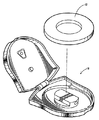
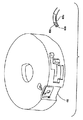
本発明は、そのさまざまな実施形態において、たとえば図1に概略的に示されているように、交換式マルチランセットカートリッジ12と組み合わせて使用されることが好ましい改良型穿刺装置10を提供する。本発明の改良は、マルチランセット穿刺装置のさまざまな形と組み合わされた用途に適用可能であるが、参照によって本明細書に援用されるPCT国際公開第WO03/071940A1号は、本発明の改良を適用できる可能性があるマルチランセット穿刺装置の例示的な形を示している。本明細書に開示されている改良は個別の利点であり、又は互いに組み合わせて使用されることができることを認識されたい。一般的に、本発明の穿刺装置10は、カートリッジを受け取るためのチャンバを画定するハウジングと、カートリッジの活動ランセットを穿刺行程でカートリッジ内の後退位置から、活動ランセットのとがった先端がハウジング内のランセット開口を通って突出し、それにより、被験者の皮膚の予定穿刺場所を突き刺す前進位置へ推進するための駆動機構と、駆動機構に給電するための充電機構と、カートリッジのランセットを活動位置内へ、又それを通過するように順次前進させる前進機構とを有する。これらの機構のさまざまなものを組み合わせることができ、たとえば任意選択であるが、単一機構によって駆動機構に給電し、且つ同時に又は順次、カートリッジを前進させることができる。
The present invention provides an improved
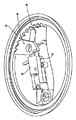
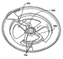
図2は、本発明の例示的な一実施形態による交換式マルチランセットカートリッジ12を示す。カートリッジ12は、好ましくは個々のランセットが作動時に横行してそれぞれの穿刺行程を定める複数のランセットガイドトラックを画定するランセットキャリヤ又はベース14を有することが好ましい。カートリッジ12は好ましくは、それぞれ対応のガイドトラック内を摺動可能である複数のランセット16を有する。各ランセット16は好ましくは、とがったランセット先端を突出させたランセット本体と、とがったランセット先端を覆う取り外し式保護エンドキャップとを有する。ランセットから取り外された保護エンドキャップを、各活動ランセットがその穿刺行程を横行するときの移動経路外へ移動させるために、好ましくは1つ又は複数のバイアス部材18が設けられている。好ましくは、カバー20がランセットの上に重なってベース14と結合し、それにより、包囲体を形成している。任意選択であるが、使用の際に穿刺装置の外側から見ることができる数字又は他の記号であって、どのランセットが使用中であるか、且つ/又は使用できるランセットがいくつ残っているか、且つ/又は装置が満載(未使用カートリッジ)且つ/又は空(使用済みカートリッジ)であることを示す数字又は他の記号をカバーに付ける。
FIG. 2 illustrates a replaceable
図3は、わかりやすくするために上側ハウジング半割シェルを取り外している、マルチランセットカートリッジ12を内部に設置した穿刺装置10を示す。上側ハウジング半割シェルは、部分的に示されているヒンジ連結部22によって下側ハウジング半割シェルに回動式に連結されるであろう。カートリッジの一連のランセット16を活動位置へ移動させるためにカートリッジを前進させ、駆動機構に給電し、活動ランセットのキャップを外すように、アーム24が回動式に動作可能である。起動ボタン又はトリガ26が駆動機構を解放し、それにより、活動ランセットをその穿刺行程で推進させる。ユーザがランセットの貫入深さを選択的に調節できるようにするために、深さ制御機構28が設けられている。
FIG. 3 shows the lancing
[前進及び割り出し]
本発明の穿刺装置の例示的な一実施形態は好ましくは、マルチランセットカートリッジの一連のランセットすなわちランセットアレイ全体を通して前進させるための1つ又は複数の機構であって、活動位置にランセットがないランセット間の位置へのカートリッジの不完全前進の防止、装置を二重起動させ、それにより、1つのランセットを活動位置に入れ、そのランセットを使用することなく通過させる前進の防止、及び/又は逆作動してランセットを再使用する可能性の防止を行うために前進を割り出す1つ又は複数の機構を有する。
[Advance and index]
One exemplary embodiment of the lancing device of the present invention is preferably one or more mechanisms for advancing through a series of lancets or lancet array of a multi-lancet cartridge, between lancets without an active position. Prevention of incomplete advancement of the cartridge to the position of the device, double activation of the device, thereby preventing the advancement of one lancet being put into the active position and passing without using the lancet and / or reverse operation One or more mechanisms for determining the advance to prevent the possibility of reusing the lancet.
たとえば図4は、本発明の例示的な実施形態によるマルチランセット穿刺装置用の逆行防止機構を示す。ラチェット及び爪機構40は、装置がランセットカートリッジ内又はその上のランセットアレイの一連のランセット全体を通して前進できるようにし、逆移動及び/又はランセット間の不完全前進を防止する。駆動ピストン42が付勢されると、好ましくは接触面44がその移動の限界で爪46に係合してラチェット48を解放し、それにより、前進及び/又はアーム機構がその通常又はデフォルト位置に戻ることができるようにする。このように、前進機構は前後方向に動作し、ユーザは機構を第1の前進方向に作動させてカートリッジに係合させ、それにより、カートリッジを次のランセットに進めることができ、また第2の逆方向に作動させてカートリッジから離脱させ、それにより、機構を元の位置に戻すことができる。代替的な実施形態では、戻り行程をまったく必要としないで、カートリッジのランセットすべてを通るように、前進機構を一方向に(すなわち、時計回り方向又は反時計回り方向に)連続作動させる。
For example, FIG. 4 illustrates a retrograde mechanism for a multi-lancet puncture device according to an exemplary embodiment of the present invention. The ratchet and pawl mechanism 40 allows the device to advance through a series of lancets in or above the lancet cartridge, preventing reverse movement and / or incomplete advancement between lancets. When the drive piston 42 is energized, preferably the
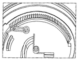
図5a〜図5cは、ねじりばね50が、カートリッジ内の協働デテント52に係合するようにしてラチェット機構を形成し、それにより、カートリッジが一連のランセット全体にわたって前進し、且つカートリッジの逆移動を防止することができるようにした逆行防止機構の別の実施形態を示す。この機構は好ましくは、一連のランセットを通る前進の割り出しも行い、それにより、ランセット間の不完全前進を防止することができる。代替的な実施形態では、カートリッジの逆移動を防止するために、摩擦クラッチ機構が設けられる。
5a-5c show that the
図6は、本発明の例示的な一実施形態によるマルチランセット穿刺装置用の回転前進機構60を示す。前進機構は、内部前進部64に連結された外部回転前進部ノブ62を有し、ユーザがノブを回転作動させるとき、内部前進部64がカートリッジに係合して、それを一連のランセット全体にわたって前進させることができる。
FIG. 6 illustrates a rotary advancement mechanism 60 for a multi-lancet lancing device according to an exemplary embodiment of the present invention. The advancement mechanism has an external
図7a及び図7bは、本発明の例示的な実施形態によるマルチランセット穿刺装置用の逆行防止機構であって、ランセットカートリッジ内の協働デテント74に係合するための歯又はフィンガ72を有する板ばね70を備え、それにより、カートリッジの一連のランセット全体にわたる割り出し及び前進を行い、且つカートリッジの逆移動を防止することができる。
7a and 7b are anti-retroversion mechanisms for a multi-lancet puncture device according to an exemplary embodiment of the present invention, with plates or
図8a及び図8bは、前進ノブ80を示し、割り出しアーム82が熱かしめ又は接着剤等によってノブの中央ハブ83に取り付けられている。アーム82は好ましくは、両端たわみ金属部材として形成されている。アームの各端部には好ましくは、ランセットカートリッジの協働機能部に係合し、それにより、カートリッジを一連のランセット全体にわたって割り出し、且つ前進させることができる第1傾斜フィンガ84と、穿刺装置ハウジング内のカム面に追従し、それにより、作動シーケンスの適当な位置でカートリッジに対して係脱するように割り出しアーム82をたわませることができる第2傾斜フィンガ86とが設けられている。この機構により、戻り行程を必要としないで、前進ノブ80を一方向に、各割り出しステップで180°ずつ回転作動させることができる。好ましくは、各端部の傾斜フィンガの近くに、対称的なガイド及び前進機構を配置する。
FIGS. 8a and 8b show the
[ランセット及びエンドキャップの保持]
本発明の穿刺装置の例示的な実施形態は好ましくは、活動ランセット位置で駆動機構に係合する位置に前進させられるまで、ランセットをマルチランセットカートリッジ内又はその上の所定位置に保持するための機能部も有する。このようにして、不注意によるランセットのカートリッジからの放出、詰まり及び/又はカートリッジ内で緩んだランセットのがたつきによる騒音が防止される。穿刺装置は好ましくは、活動ランセットから取り外された保護エンドキャップを穿刺行程に沿ったランセットの移動経路外へ退去させ、且つ取り外されたエンドキャップを保持する機能部も備える。
[Retention of lancet and end cap]
An exemplary embodiment of the lancing device of the present invention preferably has the capability to hold the lancet in place in or on the multi-lancet cartridge until it is advanced to a position that engages the drive mechanism in the active lancet position. It also has a part. In this way, inadvertent release of the lancet from the cartridge, clogging and / or noise due to loose lancet rattling within the cartridge are prevented. The puncture device preferably also includes a functional part for moving the protective end cap removed from the active lancet out of the path of movement of the lancet along the puncture stroke and holding the removed end cap.
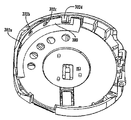
たとえば、図9は、ランセット保持リング92を有する本発明の例示的な実施形態によるマルチランセットカートリッジ90を示し、その保持リングは、リング92のスプリット又は開口部分の下方の発射位置又は「活動」位置内へ前進するまで、ランセットが半径方向に移動しないようにする。リングの協働トラック、チャネル又は縁部に係合するように、各ランセットに保持ピン又は突起94を設けることができる。任意選択であるが、リング92に制限部材96を設けて、ランセットカートリッジがランセット全体にわたって前進した後、それがさらに前進するのを防止し、それにより、ランセットの再使用を防止する。
For example, FIG. 9 shows a
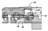
図10a及び図10bは、ランセットが活動位置内へ前進するまで、ランセットをカートリッジ内の所定位置に保持するために、カートリッジの上部カバー部分内に複数の成形カンチレバー100を形成した本発明の一実施形態を示す。各カンチレバー上のランセット保持ピン102がそれぞれのランセット104に係合し、それにより、ランセットが活動位置内へ前進し、そこでリフタ106がカンチレバー100に係合し、それをたわませて活動ランセット104から離脱させ、それによってランセットを解放して発射できるようにするまで、ランセットを所定位置に保持することができる。
FIGS. 10a and 10b illustrate one implementation of the invention in which a plurality of molded
図11a及び図11bは、複数の個別ばねループ114を取り付けた平坦なプレス加工ばねリング112を有するカートリッジカバー110を示す。ばねリング112は好ましくは、ばねリングの穴をチナーマン型ピン上に圧入することによってカバー110に取り付けられ、カバーから突出している隆起リング又はフランジ116が、組み立て中に各ばねループ114を外向きにたわませ、それにより、ループに予荷重を与えて、活動位置にあるランセットから取り外したとき、エンドキャップをランセットアレイの平面外へ付勢できるようにする。このように取り付けられた平坦なばねリングを設けることは、製造及び組み立て中の取り扱いが、事前屈曲ばね部材を形成するよりも容易且つ低コストであることがわかっている。組み立て中のさらなる利点を得るために、製造中に自動小分けが行われるように、複数のそのようなばねリングを接続ストリップ、又は積み重ねアレイにして設けてもよい。
FIGS. 11 a and 11 b show a
図12は、各ランセット126の保護キャップ124に係合して、ランセットキャップを同一平面上で側方に取り外すことができるようにする横方向付勢ばね部材122を有するカートリッジ120を示す。ばね部材122は、組み立て時に予荷重をかけられ、そのため、キャップ124をランセット126から取り外したとき、ばね部材がキャップを側方に引っ張り、活動ランセットの移動経路外へ出す。この構造は、取り外されたエンドキャップをランセットアレイと同一平面上であるが、活動ランセットの移動経路外に保管することができるようにし、それにより、必要なカートリッジ厚さが、取り外されたエンドキャップをランセットの平面の下方又は上方の窪み又はリセス内に保管するカートリッジと比べて薄くなる。
FIG. 12 shows a
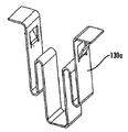
図13a〜図13cは、個別の各ランセットの保護エンドキャップに係合して後退させるための個別のばねクリップ部材を提供するマルチランセットカートリッジに使用される個別ばねクリップ130の代替的な実施形態を示す。さらなる代替的な実施形態では、2つ以上(たとえば、2、4、5又は10個)の連結ばねクリップをばねセグメント又はストリップとして形成して、1つのばねクリップが各ランセットエンドキャップに係合するようにして多数のセグメントを設置する。 FIGS. 13a-13c show an alternative embodiment of an individual spring clip 130 used in a multi-lancet cartridge that provides an individual spring clip member for engaging and retracting the protective end cap of each individual lancet. Show. In further alternative embodiments, two or more (eg, 2, 4, 5 or 10) connecting spring clips are formed as spring segments or strips, with one spring clip engaging each lancet end cap. In this way, a large number of segments are installed.
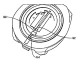
図14は、本発明の別の実施形態によるカートリッジの、組み立て及び使用中にランセットを所定位置に保持するための弾性ランセット押さえスナップ140を有する部分を示す。ランセットは、押さえスナップ間を自由に摺動することができるが、スナップはランセットがカートリッジから変位することを防止する。任意選択であるが、スナップは発射中のランセットの移動の方向ガイドとしても機能する。
FIG. 14 shows a portion of a cartridge according to another embodiment of the present invention having an elastic lancet hold-
[カートリッジの位置合わせ]
本発明の穿刺装置の例示的な実施形態は好ましくは、装置の駆動機構が給電される(すなわち、その起動配置にある)とき、カートリッジを所定位置に固定するための回転止め連動機能部も備える。このように、適当なランセット位置合わせが維持され、駆動機構内の振動及び遊びが減少する。
[Cartridge alignment]
Exemplary embodiments of the puncture device of the present invention preferably also include a rotation stop interlocking feature for securing the cartridge in place when the drive mechanism of the device is powered (ie, in its activated configuration). . In this way, proper lancet alignment is maintained and vibration and play in the drive mechanism is reduced.
たとえば、図15は、マルチランセット穿刺装置用の回転止め連動機構を示し、ランセット係合ジョー154と反対側の駆動ピストン152の遠位端から突出しているアーム150を有する。駆動機構の起動時に、アームはランセットカートリッジの協働リセス又は他の表面機能部に係合し、それにより、カートリッジの移動を防止するが、発射後のカートリッジの前進を可能にする。
For example, FIG. 15 shows an anti-rotation interlocking mechanism for a multi-lancet puncture device having an
図16a及び図16bに示されているような他の例示的な実施形態では、回転止め連動機能部は、駆動機構の起動時に駆動ピストン162と接触することによって後退し、それにより、ランセットカートリッジに係合してそれを所定位置にロックするロックボルト160を有する。ロックボルト160の下面上の突起164が、前進機構上の協働機能部とかみ合って、カートリッジのさらなる前進を阻止し、それによって二重起動及び/又は潜在的な詰まりを防止する。他の実施形態では、装置は、ランセットを所定位置に保持し、且つ装置の起動時にランセットカートリッジの回転を防止することによって二重起動及び/又は再使用を防止するラチェット式保持リングを備える。
In other exemplary embodiments, such as those shown in FIGS. 16a and 16b, the detent interlock feature is retracted by contacting the
図17は、カートリッジの一連のランセット全体にわたって前進させるときにカートリッジを割り出し、且つカートリッジの逆移動を防止するために、ランセットカートリッジ内の協働デテントに係合する傾斜肩部を有するばね式プランジャ170を有する本発明の一実施形態を示す。
FIG. 17 illustrates a spring-loaded
任意選択であるが、本発明のマルチランセットカートリッジは、汚染の可能性があるランセットを誤って再使用することを防止するために、新しいカートリッジを使用済みカートリッジから区別する剥離部分も有する。たとえば、ユーザが手動で変位させるか、ハウジング内への挿入時、又は最初の前進又は発射時にカートリッジから自動的に折り取られるか、他の方法で変位されるフラッグ又はインジケータを設けることができる。そのさまざまな実施形態では、超音波溶接、スナップ、クラッシュピン、溶剤結合、接着剤、熱溶接及び/又はレーザ溶接の1つ又は複数を含む組み立て方法を使用して、カートリッジを組み立てることができる。 Optionally, the multi-lancet cartridge of the present invention also has a peel-off portion that distinguishes the new cartridge from the used cartridge to prevent accidental reuse of a potentially contaminated lancet. For example, a flag or indicator can be provided that is manually displaced by the user, automatically folded from the cartridge upon insertion into the housing, or upon initial advance or firing, or otherwise displaced. In various embodiments thereof, the cartridge can be assembled using an assembly method that includes one or more of ultrasonic welding, snaps, crush pins, solvent bonding, adhesives, thermal welding and / or laser welding.
[駆動機構及び作動]
本発明の穿刺装置の例示的な実施形態は好ましくは、改良型駆動機構及び/又は改良型作動(すなわち、トリガ)機構も有する。たとえば、図18は、本発明の例示的な実施形態によるマルチランセット穿刺装置用の駆動機構の一部分であって、穿刺装置の二重起動を防止し、それにより、詰まる可能性を低減させるために、駆動ピストン上の協働連動フィン182に係合するようにした片持ち式たわみ連動ばねアーム180と、機構ベース内の補強リブ184とを有する部分を示す。図示の動作シーケンスにおいて、ユーザが前進機構を回転させ始めるとき、ピストン182は前方(発射)位置にある。連動アーム180がピストンを通過移動し、ピストンはその後方(充電)位置にロックされる。次に、前進機構はその戻り行程に沿って戻され、連動アーム180はピストン182の下でたわむ。次に、連動機構180が曲がって上に戻り、前進機構をロックする。ピストンが充電され、補強リブ184がピストン182の連動フィンの屈曲を防止する。
[Drive mechanism and operation]
Exemplary embodiments of the lancing device of the present invention preferably also have an improved drive mechanism and / or an improved actuation (ie, trigger) mechanism. For example, FIG. 18 is a portion of a drive mechanism for a multi-lancet lancing device according to an exemplary embodiment of the present invention to prevent double activation of the lancing device and thereby reduce the possibility of clogging. , Shows a portion having a cantilevered flexure interlocking
図19は、駆動ばね192又は戻しばね194の一方を外側に取り付けて外側肩部に当接させ、且つ駆動又は戻しばねの他方をピストンの遠位端の内孔の内側に取り付けて同軸入れ子式にした一直線配列のピストンアセンブリ190を有する駆動機構を示す。対向するばねは縦一列に並んで動作し、それにより、ピストン(及びそれに結合された活動ランセット)をその穿刺行程で前進且つ後退させる。
FIG. 19 shows a coaxial telescope with one of the
図20は、駆動ピストン202の横でカートリッジ内又はその上のランセットアレイの平面上に、側方にずらした後退ばね200を有する駆動機構の別の実施形態を示す。後退ばね200は、ピストン202の側方突出アーム204を押し付ける。駆動ばね206は、ピストン202と一直線に並び、ピストンの遠位端を押し付ける。
FIG. 20 shows another embodiment of a drive mechanism having a
図21は、本発明の例示的な一実施形態による改良型トリガ機構を示す。解放ボタン210の作動により、ボタンに連結されているフィンガ212が摺動ケージ216の傾斜面214に沿って駆動されて、ケージを横方向に移動させ、且つ逆鉤面(sear surface)217を移動させて駆動ピストン218から離脱させ、それにより、ピストンを解放して装置を発射させる。
FIG. 21 illustrates an improved trigger mechanism according to an exemplary embodiment of the present invention. Actuation of the
図22〜図26は、本発明の例示形によるシャッタトリガ機構のさまざまな代替的な実施形態を示す。一般的に、駆動ピストン222から延出しているバーブ(barb)又は拡張部分220が、シャッタ又は解放部材226内に形成された開口224に離脱可能に係合する。解放部材226を作動させ、それによってバーブ又は拡張部分220を開口224から離脱させて、穿刺装置を発射させることができる。図26の実施形態では、鍵穴形開口224が、拡大部分220を通過させることができる大径部分と、駆動ピストンの小径の一部分に係合するためのより小径の部分とを有する。好ましくは、アクチュエータボタン228又は他の部材が穿刺装置ハウジングの外部に設けられ、フィンガ又は他の突起230がハウジングを貫通して延出して解放部材と接触し、それにより、装置を作動させることができる。好ましくは、発射後にシャッタを準備状態に戻すために、1つ又は複数のばね部材232が設けられる。
22-26 illustrate various alternative embodiments of a shutter trigger mechanism according to an exemplary form of the present invention. In general, a barb or
図27a及び図27bは、駆動ピストン278の遠位端から突出したバーブ付き又は傾斜アーム276に解放可能に係合するように開口274を内部に形成した解放部材272に結合されているたわみアーム271に取り付けられたアクチュエータボタン270を有するたわみトリガボタン機構を示す。ボタン270を押すと、解放部材272がアーム276から離脱し、それにより、ピストン278を解放して装置を発射させる。図28の実施形態では、トリガ解放部材280が、駆動ピストン282と一体成形されている。
27a and 27b show a
図29a及び図29bは、支持台292の一方側に解放ボタン290を、支持台の反対側に解放又は逆鉤面294を有するヒンジ式トリガ機構を示す。ボタン290を押し下げると、逆鉤面294が上昇して、駆動ピストンから突出している協働トリガアーム296から離脱し、駆動ピストンを解放して装置を発射させる。好ましくは、戻しばね298がトリガ機構内に一体状に成形されている。
FIGS. 29a and 29b show a hinged trigger mechanism having a
他の実施形態では、装置は、ランセットカートリッジの上部カバー内に成形されたトリガを有する。たとえば、トリガボタン及び開放アームの少なくとも一部分を可撓性材料で形成する等により、トリガボタン及び解放アームを上部カバーと一体成形してもよい。さらに別の代替的な実施形態では、片持ち式トリガアームが駆動ピストンの横に並んで延在し、駆動ピストンの協働表面に離脱可能に係合した自由端を有する。トリガアームの自由端は、たわんで駆動ピストンから離脱し、それによって装置を発射させる。 In other embodiments, the device has a trigger molded in the top cover of the lancet cartridge. For example, the trigger button and release arm may be integrally formed with the top cover, such as by forming at least a portion of the trigger button and release arm from a flexible material. In yet another alternative embodiment, a cantilever trigger arm extends alongside the drive piston and has a free end releasably engaged with a cooperating surface of the drive piston. The free end of the trigger arm flexes away from the drive piston, thereby firing the device.
[深さ調節]
本発明の穿刺装置の例示的な実施形態は好ましくは、皮膚の穿刺場所へのランセット先端の貫入深さをユーザが選択的に変えることができるようするための改良型深さ制御機構も有する。たとえば、図30は、穿刺深さを調節するために複数の開口302を貫設した回転プレート300を有する、本発明の例示的な実施形態による深さ制御機構を示す。深さ調節は、たとえば異なった深さ及び/又は直径の開口をプレート30の壁に貫設すること、プレートの壁を、その長さ方向の異なった地点で異なった厚さを有するように形成すること、及び/又は壁を異なった角位置で異なった量だけ半径方向にずらして形成することによって達成されることができる。たとえば、外部アクチュエータ部材によって穿刺装置のハウジング内でプレートを回転させることにより、所望の開口をハウジングに貫設されたランセット開口と整合させる。
[Depth adjustment]
The exemplary embodiment of the puncture device of the present invention preferably also has an improved depth control mechanism to allow the user to selectively change the penetration depth of the lancet tip into the skin puncture site. For example, FIG. 30 illustrates a depth control mechanism according to an exemplary embodiment of the present invention having a
図31は、回動式行程制限深さ制御ストッパ310を示す。ランセットは、各々が異なった貫入深さを与える複数の行程制限表面312を有する段差付き表面を設けたほぼ弓形の接触面に当たる。ユーザは、深さストッパを軸314を中心にして回動させ、それにより、接触面の段差付き表面の選択部分を活動ランセットと接触するように一直線に並べて位置付け、それにより、所望の穿刺深さを選択することができる。
FIG. 31 shows a rotary stroke limit
図32は、並進方向摺動プレート部材326の協働開口内に回転式に取り付けられた偏心ハブ324を有するダイアル部材322を備えたスライドプレート深さ制御機構320を示す。ダイアル332の回転により、穿刺装置ハウジングのランセット開口を取り囲む接触面328の位置を調節し、それにより、貫入深さを変化させる。
FIG. 32 shows a slide plate
代替的な実施形態では、異なった穿刺深さを与えるために、交換式ランセットカートリッジを異なった「サイズ」で提供する。たとえば、カートリッジを「浅い」、「中間」及び「深い」サイズで販売することができ、ユーザは所望サイズを購入する。標準穿刺装置で使用されるように、カートリッジは相互交換可能であり、たとえばランセット針長さや壁厚等を変化させることにより、深さを変化させることができる。さらに別の実施形態では、穿刺装置のハウジング内でのカートリッジ及び/又は駆動機構の位置を変化させるために、ねじ駆動式ラック等の位置調節機構が設けられる。さらに他の実施形態では、深さを制御するために、ランセット駆動機構の戻しばね及び/又は駆動ばねの位置又はばね定数(剛さ)を変更することができる。 In alternative embodiments, replaceable lancet cartridges are provided in different “sizes” to provide different puncture depths. For example, cartridges can be sold in “shallow”, “medium” and “deep” sizes, and the user purchases the desired size. As used in standard lancing devices, the cartridges are interchangeable, and the depth can be varied, for example, by varying the lancet needle length, wall thickness, and the like. In yet another embodiment, a position adjustment mechanism, such as a screw driven rack, is provided to change the position of the cartridge and / or drive mechanism within the housing of the lancing device. In still other embodiments, the position or spring constant (rigidity) of the return spring and / or drive spring of the lancet drive mechanism can be changed to control the depth.
図33は、位置決めねじ332の作動を介して縦一列に並んで移動し、それにより、深さ調節を行う前後ストッパを有する可動式スロットルプレート330を組み込んだ深さ制御機構を示す。
FIG. 33 shows a depth control mechanism that incorporates a
図34の深さ制御機構は、ランセット装置ハウジング344内の協働ねじ付き開口342内に取り付けられた、中心にランセット開口を貫設した円形ねじ付きプレート340を備える。プレートを旋回させ、それにより、それをハウジングの壁に対して内外にねじって、穿刺深さを制御するために、ランセットの行程を制限するための可変内部接触面、及び/又はランセット開口を取り囲む可変深さリセスを与える。
The depth control mechanism of FIG. 34 comprises a circular threaded
図35は、ハウジング422に回転式に取り付けられて、互いに角方向にずらした異なった直径の複数のランセット開口424を有する円形深さホィール420を備える深さ制御機構を示す。ユーザは、ホィール420を回転させ、それにより、ランセット開口の選択された1つを活動ランセットの移動経路に整合させ、それにより、貫入深さを変化させる。任意選択であるが、ユーザに選択貫入深さを知らせるために、深さホィール420上に、又はそれに連結された数字又は表示426をハウジングの外から見えるように設ける。
FIG. 35 shows a depth control mechanism comprising a
図36は、ハウジングに回転式に取り付けられたテーパ厚さ形深さホィール(tapered-thickness depth wheel)360を有する深さ制御機構を示す。深さホィールは、角方向にずらした複数のランセット開口を画定し、円周に沿って変化する壁厚(すなわち、ディスクの周囲の異なった角変位で異なった厚さ)を有する。壁厚が変化することにより、ユーザは、深さホィールを回転させ、それによってランセット開口の一つの選択されたものを活動ランセットの移動経路に整合させることにより、所望の穿刺深さを選択することができる。
FIG. 36 shows a depth control mechanism having a taper-
図37の深さ制御機構は、貫入深さを変化させるために穿刺場所に押し付けられる位置調節可能な接触面372を備えるスライドプレート370を有する。プレート上のピン374が、深さ調節ホィール378の偏心弓形カムスロット376内に係合し、このホィールをユーザが回転させ、それにより、ハウジングのランセット行程制限表面に対する接触面の位置を変化させて、貫入深さを調節することができる。
The depth control mechanism of FIG. 37 has a
図38は、穿刺からの貫入深さを変化させるために穿刺場所に押し付けられる位置調節可能な接触面382を備えるスライドプレート380を有する深さ制御機構を示す。ねじ駆動機構384が、接触面の位置の調節を行う。図39は、穿刺からの貫入深さを変化させるために穿刺場所に押し付けられる位置調節可能な接触面392を備えるスライドプレート390を有する同様な深さ制御機構を示す。歯車駆動式ねじ付きロッド394が、一端部でスライドプレート390のねじ付きスリーブ部分内に係合して、接触面の位置の調節を行う。
FIG. 38 shows a depth control mechanism having a
図40は、ランセット装置のハウジングの有効壁厚を変化させ、それにより、穿刺深さを制御するための1つ又は複数のシャッタ400を有する深さ制御機構を示す。各シャッタにランセット開口を貫設されており、また各シャッタは、そのランセット開口が活動ランセットの移動経路に整合する第1位置と、活動ランセットの移動経路から離れる第2位置との間を移動することができる。連続シャッタをそれぞれの第1位置へ移動させるとき、それらの累積厚さが、ランセット本体の前面と穿刺場所との間隔を増加させ、それにより、貫入深さを減少させる。隣接したシャッタは、互いに半径方向にずれており、そのため、シャッタの1つ、2つ又はそれ以上を選択的に開閉し、それにより、穿刺深さを変化させることができる。
FIG. 40 shows a depth control mechanism having one or
深さ制御機構は、たとえば図41aに示されているように、調節部材412に固着された、又はそれと一体成形された深さ制御部材410であって、長さ方向に厚さが変化する傾斜厚さ制御部材が、調節ノブから半径方向に突出している深さ制御部材410を有することができる。代替として、深さ制御機構は、たとえば図41b〜図41fに示されているように、直接的に、又は歯車又は他のリンク手段によって間接的に連結された個別の深さ制御部材及び調節部材を有する。 The depth control mechanism is a depth control member 410 fixed to the adjustment member 412 or integrally formed with the adjustment member 412, as shown in FIG. 41a, for example. The thickness control member can have a depth control member 410 that projects radially from the adjustment knob. Alternatively, the depth control mechanism may be a separate depth control member and adjustment member connected directly or indirectly by gears or other linking means, eg, as shown in FIGS. 41b-41f. Have
図42aの回動式深さ制御部材420aの角位置を歯車駆動部422aで調節し、それにより、段差付き接触面424aの1つを選択的に位置付けて、ランセットの行程を制限することができる。図42bの回動式深さ制御部材420bの角位置は、スライドピボット継手424bを有するトグルリンク機構422bを介して調節され、それにより、段差付き接触面426bの1つを選択的に位置付けて、ランセットの行程を制限することができる。
The angular position of the pivotable depth control member 420a of FIG. 42a can be adjusted by the
図43の深さ制御機構は、調節ノブ432に取り付けられた軸方向平歯車430であって、歯付きトラック434を駆動して、深さ制御部材436の選択された接触面部分を整合させ、それにより、ランセットの行程を制限し、それによって貫入深さを制御することができる。深さ制御部材は、段差付き接触面(436)又は傾斜接触面(436’)を有することができる。任意選択であるが、デテント付きカンチレバー438を設けて、平歯車430の歯付き表面と接触させ、それにより、割り出し及びユーザへの触覚フィードバックを行うことができる。
The depth control mechanism of FIG. 43 is an
図44の深さ制御機構は、向き合った半割体440a、440bを有する幅調節可能なスライド絞りであって、半割体を互いに接離する方向に移動させて、開口寸法を減少又は増加させ、それにより、被験者の皮膚が開口内に膨出する程度を変化させて貫入深さを変化させることができる、幅調節可能なスライド絞りを有する。開口寸法が大きいほど、より深い穿刺を行うことができるように穿刺場所の皮膚をその中にさらに受け取り、また、開口寸法が小さいほど、より浅い穿刺が行われる。図45は、回動接触プレート450を有する深さ制御機構を示し、回動接触プレート450の位置は、ハウジング456へのヒンジ式接続部454によって穿刺カートリッジ452の位置に対する角度が変化可能であり、それにより、貫入深さを調節することができる。
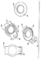
The depth control mechanism of FIG. 44 is an adjustable slide slide having opposed halves 440a, 440b that move the halves in the direction of moving away from each other to reduce or increase the opening size. , Thereby having a slide diaphragm with an adjustable width that can change the penetration depth by changing the degree to which the subject's skin bulges into the opening. The larger the opening size, the more the skin at the puncture site is received therein so that a deeper puncture can be performed, and the smaller the opening size, the shallower the puncture is performed. FIG. 45 shows a depth control mechanism having a
図46は、皮膚の穿刺場所に押し付けられる接触面460を有する深さ制御機構であって、接触面は、一端部が他端部より幅広になっているテーパスロット462を有する、深さ制御機構を示す。穿刺開口464に対するテーパスロットの位置の調節によって有効開口寸法が変化し、それにより、貫入深さが変化する。
FIG. 46 is a depth control mechanism having a
図47は、皮膚の穿刺場所に押し付けられる接触面を画定し、且つハウジングのランセット開口の前方でハウジング全体を選択的に移動可能なたわみスライドバンド470を有する深さ制御機構を示す。バンド470の厚さは、その長さ方向に変化し、且つ/又はバンドに貫設された開口(複数可)472の大きさが変化し、それによって穿刺深さが調節される。歯車付き調節ノブ474a、又はピン・デテントスライド連結部474bが、ハウジングに対するバンド470の位置調節を行う。調節ノブ474aの歯車面は、図示のようなバンドの前面又は背面上の歯付き表面で垂直方向に動作することができ、又はバンドの上縁部又は下縁部上の歯付き表面で水平方向に動作することができる。開口に隣接した窓を通して見ることができるように、深さ表示器をそれぞれ調節ノブ(476a)又はスライド連結部(476b)上又はその近くに、且つ/又はバンド(476b’)に沿って設けることができる。任意選択であるが、代替場所の穿刺用として、バンド470をハウジングに貫設されたランセット開口から完全に外れるように移動させ、それにより、最大穿刺深さを与えることができる。代替形式では、バンドは、皮膚の穿刺場所に押し付けられる接触面の背後でハウジング内を摺動し、それにより、ランセットの行程を制限し、且つ/又は開口寸法を変化させ、それによって貫入深さを制御することができる。 FIG. 47 illustrates a depth control mechanism having a flexible slide band 470 that defines a contact surface that is pressed against the skin puncture site and that is selectively movable throughout the housing in front of the housing lancet opening. The thickness of the band 470 varies along its length and / or the size of the opening (s) 472 penetrating the band changes, thereby adjusting the puncture depth. A geared adjustment knob 474a or a pin / detent slide coupling 474b adjusts the position of the band 470 relative to the housing. The gear face of the adjustment knob 474a can move vertically on the toothed surface on the front or back of the band as shown, or horizontally on the toothed surface on the upper or lower edge of the band Can work. A depth indicator is provided on or near the adjustment knob (476a) or slide connection (476b) and / or along the band (476b ′), respectively, so that it can be seen through the window adjacent to the opening. Can do. Optionally, for alternate location puncture, the band 470 can be moved completely away from the lancet opening through the housing, thereby providing maximum puncture depth. In an alternative form, the band slides in the housing behind a contact surface that is pressed against the skin puncture site, thereby limiting the travel of the lancet and / or changing the opening dimension and thereby the penetration depth. Can be controlled.
図48の深さ制御機構は、スライドプレート482の位置を(方向矢印484によって示された)第1軸に沿って前進及び後退させるためのラック・ピニオン駆動機構480を有し、スライドプレートは、穿刺深さを調節するために皮膚の穿刺場所と接触する接触面を有する。任意選択であるが、スライドプレート482は、第1軸に対して垂直方向の(方向矢印486によって示された)第2軸に沿って摺動することができ、それにより、代替場所の穿刺用として、プレートを活動ランセットの経路外へ移動させて、最大穿刺深さを与えることができる。
The depth control mechanism of FIG. 48 has a rack and
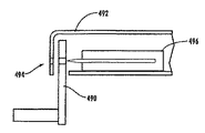
図49は、深さ調節インサート部材490であって、ランセット開口494に近接した位置で装置ハウジング492への挿入、又はそれからの後退を選択的に行うことができるフランジを有し、それにより、ランセット496の行程を制限し、それによって貫入深さを変化させる深さ調節インサート部材490を示す。
FIG. 49 shows a depth
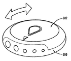
図50は、異なった寸法の開口を有する外側ハウジング500と、ハウジング内に回転可能に取り付けられて、活動ランセットに整合するように開口の1つを選択し、それによって穿刺深さを制御する内側機構502とを有する深さ制御機構を示す。図51は、変化する壁厚及び/又は開口寸法を有する外側スライドプレート510であって、ハウジングに沿って選択的に移動可能であり、それにより、開口の1つを活動ランセットに整合させ、それによって穿刺深さを変化させる外側スライドプレート510を有する深さ制御機構を示す。任意選択であるが、スライドプレート510は、上側及び下側ハウジング半割体を互いに固定するためのラッチとしても機能する。
FIG. 50 shows an
図52は、穿刺装置機構ベース522と底部ハウジング包囲体524との間に回転式に捕らえられた連続深さ調節リング520を有する深さ制御機構を示す。リング520は、穿刺深さを制御するために、異なった開口寸法及び/又は壁厚を有する。リング520の1箇所又は複数箇所に底部ハウジング包囲体524内の開口(複数可)526を通してハウジングの外部から触れることができ、それにより、ユーザがリングを回転調節することができる。
FIG. 52 shows a depth control mechanism having a continuous
図53は、ハウジングの外側に沿って移動可能に取り付けられ、且つ穿刺深さを制御するために、異なった開口寸法及び/又は壁厚を有する深さ調節バンド530を有する深さ制御機構を示す。好ましくは、深さ調節バンド530の位置付けを制御するために、スライド調節ノブ532が設けられる。
FIG. 53 shows a depth control mechanism having a
好適且つ例示的な実施形態を参照しながら本発明を説明してきたが、添付の特許請求の範囲によって定義される本発明の範囲内においてさまざまな修正、追加及び削除が行われることは、当業者には理解されるであろう。 While the invention has been described with reference to preferred and exemplary embodiments, it will be appreciated by those skilled in the art that various modifications, additions and deletions can be made within the scope of the invention as defined by the appended claims. Will be understood.
Claims (25)
A puncture device used in combination with a multi-lancet cartridge having a plurality of lancets, a housing, a drive mechanism, an advance mechanism for sequentially engaging the lancets of the multi-lancet cartridge with the drive mechanism, A puncture device comprising a depth control mechanism that adjusts a penetration depth of a lancet that is active.
Applications Claiming Priority (2)
| Application Number | Priority Date | Filing Date | Title |
|---|---|---|---|
| US51923203P | 2003-11-12 | 2003-11-12 | |
| PCT/US2004/037788 WO2005046477A2 (en) | 2003-11-12 | 2004-11-12 | Lancing device and multi-lancet cartridge |
Publications (2)
| Publication Number | Publication Date |
|---|---|
| JP2007510524A true JP2007510524A (en) | 2007-04-26 |
| JP2007510524A5 JP2007510524A5 (en) | 2008-01-10 |
Family
ID=34590378
Family Applications (1)
| Application Number | Title | Priority Date | Filing Date |
|---|---|---|---|
| JP2006539897A Pending JP2007510524A (en) | 2003-11-12 | 2004-11-12 | Puncture device and multi-lancet cartridge |
Country Status (4)
| Country | Link |
|---|---|
| US (3) | US20050154410A1 (en) |
| EP (1) | EP1684634A2 (en) |
| JP (1) | JP2007510524A (en) |
| WO (1) | WO2005046477A2 (en) |
Cited By (2)
| Publication number | Priority date | Publication date | Assignee | Title |
|---|---|---|---|---|
| JP2012518178A (en) * | 2009-02-19 | 2012-08-09 | エフ.ホフマン−ラ ロシュ アーゲー | Method for producing an analytical magazine |
| JP2017200594A (en) * | 2012-01-18 | 2017-11-09 | エフ ホフマン−ラ ロッシュ アクチェン ゲゼルシャフト | Analysis system for examining body fluid and operation method of analysis system |
Families Citing this family (140)
| Publication number | Priority date | Publication date | Assignee | Title |
|---|---|---|---|---|
| US6036924A (en) | 1997-12-04 | 2000-03-14 | Hewlett-Packard Company | Cassette of lancet cartridges for sampling blood |
| US6391005B1 (en) | 1998-03-30 | 2002-05-21 | Agilent Technologies, Inc. | Apparatus and method for penetration with shaft having a sensor for sensing penetration depth |
| US8641644B2 (en) | 2000-11-21 | 2014-02-04 | Sanofi-Aventis Deutschland Gmbh | Blood testing apparatus having a rotatable cartridge with multiple lancing elements and testing means |
| US7699791B2 (en) | 2001-06-12 | 2010-04-20 | Pelikan Technologies, Inc. | Method and apparatus for improving success rate of blood yield from a fingerstick |
| US9427532B2 (en) | 2001-06-12 | 2016-08-30 | Sanofi-Aventis Deutschland Gmbh | Tissue penetration device |
| WO2002100252A2 (en) | 2001-06-12 | 2002-12-19 | Pelikan Technologies, Inc. | Blood sampling apparatus and method |
| US9795747B2 (en) | 2010-06-02 | 2017-10-24 | Sanofi-Aventis Deutschland Gmbh | Methods and apparatus for lancet actuation |
| US9226699B2 (en) | 2002-04-19 | 2016-01-05 | Sanofi-Aventis Deutschland Gmbh | Body fluid sampling module with a continuous compression tissue interface surface |
| US7981056B2 (en) | 2002-04-19 | 2011-07-19 | Pelikan Technologies, Inc. | Methods and apparatus for lancet actuation |
| WO2002100254A2 (en) | 2001-06-12 | 2002-12-19 | Pelikan Technologies, Inc. | Method and apparatus for lancet launching device integrated onto a blood-sampling cartridge |
| WO2002100251A2 (en) | 2001-06-12 | 2002-12-19 | Pelikan Technologies, Inc. | Self optimizing lancing device with adaptation means to temporal variations in cutaneous properties |
| US8337419B2 (en) | 2002-04-19 | 2012-12-25 | Sanofi-Aventis Deutschland Gmbh | Tissue penetration device |
| US7041068B2 (en) | 2001-06-12 | 2006-05-09 | Pelikan Technologies, Inc. | Sampling module device and method |
| ATE485766T1 (en) | 2001-06-12 | 2010-11-15 | Pelikan Technologies Inc | ELECTRICAL ACTUATING ELEMENT FOR A LANCET |
| US7674232B2 (en) | 2002-04-19 | 2010-03-09 | Pelikan Technologies, Inc. | Method and apparatus for penetrating tissue |
| US7291117B2 (en) | 2002-04-19 | 2007-11-06 | Pelikan Technologies, Inc. | Method and apparatus for penetrating tissue |
| US7232451B2 (en) | 2002-04-19 | 2007-06-19 | Pelikan Technologies, Inc. | Method and apparatus for penetrating tissue |
| US7229458B2 (en) | 2002-04-19 | 2007-06-12 | Pelikan Technologies, Inc. | Method and apparatus for penetrating tissue |
| US7909778B2 (en) | 2002-04-19 | 2011-03-22 | Pelikan Technologies, Inc. | Method and apparatus for penetrating tissue |
| US7717863B2 (en) | 2002-04-19 | 2010-05-18 | Pelikan Technologies, Inc. | Method and apparatus for penetrating tissue |
| US7648468B2 (en) | 2002-04-19 | 2010-01-19 | Pelikon Technologies, Inc. | Method and apparatus for penetrating tissue |
| US8360992B2 (en) | 2002-04-19 | 2013-01-29 | Sanofi-Aventis Deutschland Gmbh | Method and apparatus for penetrating tissue |
| US7547287B2 (en) | 2002-04-19 | 2009-06-16 | Pelikan Technologies, Inc. | Method and apparatus for penetrating tissue |
| US7976476B2 (en) | 2002-04-19 | 2011-07-12 | Pelikan Technologies, Inc. | Device and method for variable speed lancet |
| US8702624B2 (en) | 2006-09-29 | 2014-04-22 | Sanofi-Aventis Deutschland Gmbh | Analyte measurement device with a single shot actuator |
| US7297122B2 (en) | 2002-04-19 | 2007-11-20 | Pelikan Technologies, Inc. | Method and apparatus for penetrating tissue |
| US9248267B2 (en) | 2002-04-19 | 2016-02-02 | Sanofi-Aventis Deustchland Gmbh | Tissue penetration device |
| US9314194B2 (en) | 2002-04-19 | 2016-04-19 | Sanofi-Aventis Deutschland Gmbh | Tissue penetration device |
| US7331931B2 (en) | 2002-04-19 | 2008-02-19 | Pelikan Technologies, Inc. | Method and apparatus for penetrating tissue |
| US7491178B2 (en) | 2002-04-19 | 2009-02-17 | Pelikan Technologies, Inc. | Method and apparatus for penetrating tissue |
| US7226461B2 (en) | 2002-04-19 | 2007-06-05 | Pelikan Technologies, Inc. | Method and apparatus for a multi-use body fluid sampling device with sterility barrier release |
| US8784335B2 (en) | 2002-04-19 | 2014-07-22 | Sanofi-Aventis Deutschland Gmbh | Body fluid sampling device with a capacitive sensor |
| US8267870B2 (en) | 2002-04-19 | 2012-09-18 | Sanofi-Aventis Deutschland Gmbh | Method and apparatus for body fluid sampling with hybrid actuation |
| US8221334B2 (en) | 2002-04-19 | 2012-07-17 | Sanofi-Aventis Deutschland Gmbh | Method and apparatus for penetrating tissue |
| US7892183B2 (en) | 2002-04-19 | 2011-02-22 | Pelikan Technologies, Inc. | Method and apparatus for body fluid sampling and analyte sensing |
| US9795334B2 (en) | 2002-04-19 | 2017-10-24 | Sanofi-Aventis Deutschland Gmbh | Method and apparatus for penetrating tissue |
| US7892185B2 (en) | 2002-04-19 | 2011-02-22 | Pelikan Technologies, Inc. | Method and apparatus for body fluid sampling and analyte sensing |
| US7371247B2 (en) | 2002-04-19 | 2008-05-13 | Pelikan Technologies, Inc | Method and apparatus for penetrating tissue |
| US8579831B2 (en) | 2002-04-19 | 2013-11-12 | Sanofi-Aventis Deutschland Gmbh | Method and apparatus for penetrating tissue |
| US7901362B2 (en) | 2002-04-19 | 2011-03-08 | Pelikan Technologies, Inc. | Method and apparatus for penetrating tissue |
| US7175642B2 (en) | 2002-04-19 | 2007-02-13 | Pelikan Technologies, Inc. | Methods and apparatus for lancet actuation |
| US7381184B2 (en) | 2002-11-05 | 2008-06-03 | Abbott Diabetes Care Inc. | Sensor inserter assembly |
| US8574895B2 (en) | 2002-12-30 | 2013-11-05 | Sanofi-Aventis Deutschland Gmbh | Method and apparatus using optical techniques to measure analyte levels |
| DE602004028463D1 (en) | 2003-05-30 | 2010-09-16 | Pelikan Technologies Inc | METHOD AND DEVICE FOR INJECTING LIQUID |
| EP1633235B1 (en) | 2003-06-06 | 2014-05-21 | Sanofi-Aventis Deutschland GmbH | Apparatus for body fluid sampling and analyte sensing |
| WO2006001797A1 (en) | 2004-06-14 | 2006-01-05 | Pelikan Technologies, Inc. | Low pain penetrating |
| EP1663001A2 (en) * | 2003-08-20 | 2006-06-07 | Facet Technologies, LLC | Multi-lancet device with sterility cap repositioning mechanism |
| WO2005033659A2 (en) | 2003-09-29 | 2005-04-14 | Pelikan Technologies, Inc. | Method and apparatus for an improved sample capture device |
| EP1680014A4 (en) | 2003-10-14 | 2009-01-21 | Pelikan Technologies Inc | Method and apparatus for a variable user interface |
| USD914881S1 (en) | 2003-11-05 | 2021-03-30 | Abbott Diabetes Care Inc. | Analyte sensor electronic mount |
| US7822454B1 (en) | 2005-01-03 | 2010-10-26 | Pelikan Technologies, Inc. | Fluid sampling device with improved analyte detecting member configuration |
| EP1706026B1 (en) | 2003-12-31 | 2017-03-01 | Sanofi-Aventis Deutschland GmbH | Method and apparatus for improving fluidic flow and sample capture |
| WO2005097237A1 (en) | 2004-03-31 | 2005-10-20 | Eli Lilly And Company | Injection apparatus having a needle cassette for delivering a pharmaceutical liquid |
| US8828203B2 (en) | 2004-05-20 | 2014-09-09 | Sanofi-Aventis Deutschland Gmbh | Printable hydrogels for biosensors |
| GB2414734B (en) * | 2004-06-01 | 2010-09-08 | Rosti As | Devices for retaining and presenting for use a plurality of components |
| US9775553B2 (en) | 2004-06-03 | 2017-10-03 | Sanofi-Aventis Deutschland Gmbh | Method and apparatus for a fluid sampling device |
| EP1765194A4 (en) | 2004-06-03 | 2010-09-29 | Pelikan Technologies Inc | Method and apparatus for a fluid sampling device |
| US7727166B2 (en) | 2004-07-26 | 2010-06-01 | Nova Biomedical Corporation | Lancet, lancet assembly and lancet-sensor combination |
| US8333714B2 (en) | 2006-09-10 | 2012-12-18 | Abbott Diabetes Care Inc. | Method and system for providing an integrated analyte sensor insertion device and data processing unit |
| US9398882B2 (en) | 2005-09-30 | 2016-07-26 | Abbott Diabetes Care Inc. | Method and apparatus for providing analyte sensor and data processing device |
| US8571624B2 (en) | 2004-12-29 | 2013-10-29 | Abbott Diabetes Care Inc. | Method and apparatus for mounting a data transmission device in a communication system |
| US10226207B2 (en) | 2004-12-29 | 2019-03-12 | Abbott Diabetes Care Inc. | Sensor inserter having introducer |
| US9788771B2 (en) * | 2006-10-23 | 2017-10-17 | Abbott Diabetes Care Inc. | Variable speed sensor insertion devices and methods of use |
| US7731657B2 (en) | 2005-08-30 | 2010-06-08 | Abbott Diabetes Care Inc. | Analyte sensor introducer and methods of use |
| US8613703B2 (en) | 2007-05-31 | 2013-12-24 | Abbott Diabetes Care Inc. | Insertion devices and methods |
| US9743862B2 (en) | 2011-03-31 | 2017-08-29 | Abbott Diabetes Care Inc. | Systems and methods for transcutaneously implanting medical devices |
| US7883464B2 (en) | 2005-09-30 | 2011-02-08 | Abbott Diabetes Care Inc. | Integrated transmitter unit and sensor introducer mechanism and methods of use |
| US9351669B2 (en) | 2009-09-30 | 2016-05-31 | Abbott Diabetes Care Inc. | Interconnect for on-body analyte monitoring device |
| US9259175B2 (en) | 2006-10-23 | 2016-02-16 | Abbott Diabetes Care, Inc. | Flexible patch for fluid delivery and monitoring body analytes |
| US8512243B2 (en) | 2005-09-30 | 2013-08-20 | Abbott Diabetes Care Inc. | Integrated introducer and transmitter assembly and methods of use |
| US8029441B2 (en) | 2006-02-28 | 2011-10-04 | Abbott Diabetes Care Inc. | Analyte sensor transmitter unit configuration for a data monitoring and management system |
| US9572534B2 (en) | 2010-06-29 | 2017-02-21 | Abbott Diabetes Care Inc. | Devices, systems and methods for on-skin or on-body mounting of medical devices |
| US8545403B2 (en) | 2005-12-28 | 2013-10-01 | Abbott Diabetes Care Inc. | Medical device insertion |
| US7697967B2 (en) | 2005-12-28 | 2010-04-13 | Abbott Diabetes Care Inc. | Method and apparatus for providing analyte sensor insertion |
| US20090105569A1 (en) | 2006-04-28 | 2009-04-23 | Abbott Diabetes Care, Inc. | Introducer Assembly and Methods of Use |
| EP1835848A4 (en) * | 2004-12-30 | 2009-07-29 | Pelikan Technologies Inc | Method and apparatus for analyte measurement test time |
| US8652831B2 (en) | 2004-12-30 | 2014-02-18 | Sanofi-Aventis Deutschland Gmbh | Method and apparatus for analyte measurement test time |
| US8784444B2 (en) | 2005-03-04 | 2014-07-22 | Bayer Healthcare Llc | Lancet release mechanism |
| TW200640419A (en) | 2005-03-04 | 2006-12-01 | Bayer Healthcare Llc | Lancet-release mechanism |
| US20060281187A1 (en) | 2005-06-13 | 2006-12-14 | Rosedale Medical, Inc. | Analyte detection devices and methods with hematocrit/volume correction and feedback control |
| US8048098B2 (en) | 2005-07-14 | 2011-11-01 | Bayer Healthcare Llc | Lancing device for one skin puncture |
| EP1912567B1 (en) | 2005-08-04 | 2012-12-26 | Bayer HealthCare, LLC | Small lancing device |
| WO2007041287A2 (en) | 2005-09-30 | 2007-04-12 | Intuity Medical, Inc. | Fully integrated wearable or handheld monitor |
| US8801631B2 (en) | 2005-09-30 | 2014-08-12 | Intuity Medical, Inc. | Devices and methods for facilitating fluid transport |
| US9521968B2 (en) | 2005-09-30 | 2016-12-20 | Abbott Diabetes Care Inc. | Analyte sensor retention mechanism and methods of use |
| US11298058B2 (en) | 2005-12-28 | 2022-04-12 | Abbott Diabetes Care Inc. | Method and apparatus for providing analyte sensor insertion |
| WO2007086843A2 (en) * | 2006-01-25 | 2007-08-02 | Nova Biomedical Corporation | Lancet sensor assembly and meter |
| US20070299458A1 (en) * | 2006-06-10 | 2007-12-27 | Epple John A | Renewable rotary skin lancet |
| US8016848B2 (en) | 2006-06-15 | 2011-09-13 | Abbott Diabetes Care Inc. | Lancets and methods of use |
| US7846110B2 (en) * | 2006-08-03 | 2010-12-07 | Advanced Medical Products Gmbh | Self-contained test unit for testing body fluids |
| US20100168616A1 (en) * | 2006-11-21 | 2010-07-01 | Stat Medical Devices, Inc. | Lancet device utilizing a revolver-type cartridge, revolver-type cartridge, and method of making and/or using the cartridge and the lancet device |
| EP2101654A4 (en) * | 2007-01-12 | 2013-03-06 | Facet Technologies Llc | Multi-lancet cartridge and lancing device |
| EP1990001A1 (en) * | 2007-05-10 | 2008-11-12 | Roche Diagnostics GmbH | Piercing system and fleam conveyor |
| US20100152660A1 (en) * | 2007-05-30 | 2010-06-17 | Eli Lilly And Company | Cartridge with multiple injection needles for a medication injection device |
| WO2009075907A2 (en) * | 2007-07-05 | 2009-06-18 | Facet Technologies, Llc | Multi-lancet cartridge and lancing device |
| US9392968B2 (en) * | 2008-01-23 | 2016-07-19 | Stat Medical Devices, Inc. | Lancet needle cartridge, cartridge lancet device, and method of using and making the same |
| US9386944B2 (en) | 2008-04-11 | 2016-07-12 | Sanofi-Aventis Deutschland Gmbh | Method and apparatus for analyte detecting device |
| US9833183B2 (en) | 2008-05-30 | 2017-12-05 | Intuity Medical, Inc. | Body fluid sampling device—sampling site interface |
| EP2299903B1 (en) | 2008-06-06 | 2021-01-27 | Intuity Medical, Inc. | Detection meter and mode of operation |
| WO2009148626A1 (en) | 2008-06-06 | 2009-12-10 | Intuity Medical, Inc. | Medical diagnostic devices and methods |
| US8092476B2 (en) | 2008-08-14 | 2012-01-10 | Abbott Diabetes Care Inc. | Adjustable cap and lancing device and method of use |
| US8123772B2 (en) | 2008-08-14 | 2012-02-28 | Abbott Diabetes Care Inc. | Cap for lancing device with adjustable mode of operation |
| US8029526B2 (en) | 2008-08-14 | 2011-10-04 | Abbott Diabetes Care Inc. | Cocking mechanism for lancing device |
| US8197503B2 (en) * | 2008-08-15 | 2012-06-12 | Abbott Diabetes Care Inc. | Side loading lancing device |
| US9375169B2 (en) | 2009-01-30 | 2016-06-28 | Sanofi-Aventis Deutschland Gmbh | Cam drive for managing disposable penetrating member actions with a single motor and motor and control system |
| US20100198034A1 (en) | 2009-02-03 | 2010-08-05 | Abbott Diabetes Care Inc. | Compact On-Body Physiological Monitoring Devices and Methods Thereof |
| EP2226007A1 (en) | 2009-02-19 | 2010-09-08 | Roche Diagnostics GmbH | Test element magazine with covered test fields |
| CN102325496B (en) * | 2009-02-19 | 2015-10-07 | 霍夫曼-拉罗奇有限公司 | The joint space-efficient analyzing aid stores |
| US8758267B2 (en) | 2009-03-17 | 2014-06-24 | Nova Biomedical Corporation | Modified lancet carrier for single-use lancet sensor assembly |
| US8613892B2 (en) | 2009-06-30 | 2013-12-24 | Abbott Diabetes Care Inc. | Analyte meter with a moveable head and methods of using the same |
| US9517027B2 (en) * | 2009-07-10 | 2016-12-13 | Facet Techonologies, Llc | Advancement mechanism for cartridge-based devices |
| CN101987220B (en) * | 2009-07-30 | 2013-11-13 | 德昌电机(深圳)有限公司 | Needle driving assembly for medical instrument |
| CN105686807B (en) | 2009-08-31 | 2019-11-15 | 雅培糖尿病护理公司 | Medical Devices |
| WO2011065981A1 (en) | 2009-11-30 | 2011-06-03 | Intuity Medical, Inc. | Calibration material delivery devices and methods |
| US8512367B2 (en) * | 2009-12-16 | 2013-08-20 | Facet Technologies, Llc | Blood sampling device with dual-link drive mechanism |
| WO2011081678A1 (en) * | 2009-12-31 | 2011-07-07 | Turner Richard W | Blood glucose measurement devices and methods of using the same |
| USD924406S1 (en) | 2010-02-01 | 2021-07-06 | Abbott Diabetes Care Inc. | Analyte sensor inserter |
| EP2552532A1 (en) | 2010-03-24 | 2013-02-06 | Abbott Diabetes Care, Inc. | Medical device inserters and processes of inserting and using medical devices |
| US8965476B2 (en) | 2010-04-16 | 2015-02-24 | Sanofi-Aventis Deutschland Gmbh | Tissue penetration device |
| US11064921B2 (en) | 2010-06-29 | 2021-07-20 | Abbott Diabetes Care Inc. | Devices, systems and methods for on-skin or on-body mounting of medical devices |
| US9167992B2 (en) * | 2010-11-03 | 2015-10-27 | Roche Diabetes Care, Inc. | Lancet drive system depth control method and test strip location methods |
| AU2011329876B2 (en) * | 2010-11-19 | 2014-09-18 | Eli Lilly And Company | Needle magazine for medication injection device |
| US9717452B2 (en) | 2010-12-30 | 2017-08-01 | Roche Diabetes Care, Inc. | Handheld medical diagnostic devices with lancing speed control |
| US8852123B2 (en) | 2010-12-30 | 2014-10-07 | Roche Diagnostics Operations, Inc. | Handheld medical diagnostic devices housing with sample transfer |
| US8158428B1 (en) | 2010-12-30 | 2012-04-17 | General Electric Company | Methods, systems and apparatus for detecting material defects in combustors of combustion turbine engines |
| EP3106870B1 (en) | 2011-08-03 | 2018-04-11 | Intuity Medical, Inc. | Body fluid sampling arrangement |
| CA3182961A1 (en) | 2011-12-11 | 2013-06-20 | Abbott Diabetes Care Inc | Analyte sensor devices, connections, and methods |
| JP6016942B2 (en) | 2011-12-20 | 2016-10-26 | アセンシア・ダイアベティス・ケア・ホールディングス・アーゲーAscensia Diabetes Care Holdings AG | Linear cartridge-based glucose measurement system |
| DK2802265T3 (en) * | 2012-01-10 | 2016-02-15 | Sanofi Aventis Deutschland | Device that includes the lancet |
| EP2856168B1 (en) | 2012-05-31 | 2018-01-10 | Ascensia Diabetes Care Holdings AG | Replaceable multistrip cartridge and biosensor meter |
| JP6148727B2 (en) | 2012-05-31 | 2017-06-14 | アセンシア・ダイアベティス・ケア・ホールディングス・アーゲーAscensia Diabetes Care Holdings AG | Multi test paper cartridge |
| WO2014164279A1 (en) | 2013-03-12 | 2014-10-09 | Bayer Healthcare Llc | Test strip meter with a mechanism for pushing the test strip against an optical reader |
| AU2016260547B2 (en) | 2015-05-14 | 2020-09-03 | Abbott Diabetes Care Inc. | Compact medical device inserters and related systems and methods |
| US10213139B2 (en) | 2015-05-14 | 2019-02-26 | Abbott Diabetes Care Inc. | Systems, devices, and methods for assembling an applicator and sensor control device |
| GB201620671D0 (en) * | 2016-12-05 | 2017-01-18 | Conceptomed As | Storage device |
| US11071478B2 (en) | 2017-01-23 | 2021-07-27 | Abbott Diabetes Care Inc. | Systems, devices and methods for analyte sensor insertion |
| CN108577805A (en) * | 2018-02-11 | 2018-09-28 | 西安交通大学医学院第附属医院 | A kind of novel diabetes peripheral neuropathy diagnosis and treatment viewer |
| USD1002852S1 (en) | 2019-06-06 | 2023-10-24 | Abbott Diabetes Care Inc. | Analyte sensor device |
| USD999913S1 (en) | 2020-12-21 | 2023-09-26 | Abbott Diabetes Care Inc | Analyte sensor inserter |
| CN117137596B (en) * | 2023-10-30 | 2024-01-12 | 湖南明舟医疗科技有限公司 | Puncture needle assembly and disposable puncture needle |
Citations (2)
| Publication number | Priority date | Publication date | Assignee | Title |
|---|---|---|---|---|
| US6228100B1 (en) * | 1999-10-25 | 2001-05-08 | Steven Schraga | Multi-use lancet device |
| WO2003070099A1 (en) * | 2002-02-21 | 2003-08-28 | Facet Technologies, Llc | Blood analyzer and pricking device for use in blood analysis |
Family Cites Families (115)
| Publication number | Priority date | Publication date | Assignee | Title |
|---|---|---|---|---|
| US376809A (en) * | 1888-01-24 | Wilhelm andersch | ||
| US3760809A (en) * | 1971-10-22 | 1973-09-25 | Damon Corp | Surgical lancet having casing |
| USD245040S (en) * | 1976-02-25 | 1977-07-12 | Ryder International Corporation | Surgical lancet |
| US4539988A (en) * | 1983-07-05 | 1985-09-10 | Packaging Corporation International | Disposable automatic lancet |
| US4643189A (en) * | 1985-02-19 | 1987-02-17 | W. T. Associates | Apparatus for implementing a standardized skin incision |
| US4787398A (en) * | 1985-04-08 | 1988-11-29 | Garid, Inc. | Glucose medical monitoring system |
| US5279294A (en) * | 1985-04-08 | 1994-01-18 | Cascade Medical, Inc. | Medical diagnostic system |
| US4627445A (en) * | 1985-04-08 | 1986-12-09 | Garid, Inc. | Glucose medical monitoring system |
| USD297978S (en) * | 1985-08-16 | 1988-10-04 | Baxter Travenol Laboratories, Inc. | Automatic retractable lancet for bleed time determination |
| IL80628A0 (en) * | 1985-11-18 | 1987-02-27 | Bajada Serge | Apparatus for testing the sensory system in humans or animals |
| US4797926A (en) * | 1986-09-11 | 1989-01-10 | American Telephone And Telegraph Company, At&T Bell Laboratories | Digital speech vocoder |
| US4794926A (en) * | 1986-11-24 | 1989-01-03 | Invictus, Inc. | Lancet cartridge |
| US4892097A (en) * | 1988-02-09 | 1990-01-09 | Ryder International Corporation | Retractable finger lancet |
| US5108889A (en) * | 1988-10-12 | 1992-04-28 | Thorne, Smith, Astill Technologies, Inc. | Assay for determining analyte using mercury release followed by detection via interaction with aluminum |
| US4983178A (en) * | 1988-11-14 | 1991-01-08 | Invictus, Inc. | Lancing device |
| US4974926A (en) * | 1989-04-06 | 1990-12-04 | At&T Bell Laboratories | Underwater optical fiber cable |
| US5196025A (en) * | 1990-05-21 | 1993-03-23 | Ryder International Corporation | Lancet actuator with retractable mechanism |
| DE4212315A1 (en) * | 1992-04-13 | 1993-10-14 | Boehringer Mannheim Gmbh | Blood lancet device for drawing blood for diagnostic purposes |
| US5477209A (en) * | 1992-05-01 | 1995-12-19 | Adonis Incorporated | Remote controlled safety light having increased noise discrimination |
| US5318583A (en) * | 1992-05-05 | 1994-06-07 | Ryder International Corporation | Lancet actuator mechanism |
| IL107396A (en) * | 1992-11-09 | 1997-02-18 | Boehringer Mannheim Gmbh | Method and apparatus for analytical determination of glucose in a biological matrix |
| DE4243142A1 (en) * | 1992-12-19 | 1994-06-23 | Boehringer Mannheim Gmbh | Device for in-vivo determination of an optical property of the aqueous humor of the eye |
| EP0644412A3 (en) * | 1993-09-17 | 1995-08-09 | Boehringer Mannheim Gmbh | Method for the analysis of fluids and suspensions having clinical relevance. |
| DE4337570A1 (en) * | 1993-11-04 | 1995-05-11 | Boehringer Mannheim Gmbh | Method for the analysis of glucose in a biological matrix |
| US5395388A (en) * | 1993-11-15 | 1995-03-07 | Schraga; Steven | Single unit lancet device |
| US5464418A (en) * | 1993-12-09 | 1995-11-07 | Schraga; Steven | Reusable lancet device |
| DE4415896A1 (en) * | 1994-05-05 | 1995-11-09 | Boehringer Mannheim Gmbh | Analysis system for monitoring the concentration of an analyte in the blood of a patient |
| TW275570B (en) * | 1994-05-05 | 1996-05-11 | Boehringer Mannheim Gmbh | |
| DE4417639A1 (en) * | 1994-05-19 | 1995-11-23 | Boehringer Mannheim Gmbh | Analysis of concns. of substances in a biological sample |
| US5527334A (en) * | 1994-05-25 | 1996-06-18 | Ryder International Corporation | Disposable, retractable lancet |
| US5476474A (en) * | 1994-07-27 | 1995-12-19 | Ryder International Corporation | Rotary lancet |
| US5514152A (en) * | 1994-08-16 | 1996-05-07 | Specialized Health Products, Inc. | Multiple segment encapsulated medical lancing device |
| USD376203S (en) * | 1994-10-31 | 1996-12-03 | Steven Schraga | Single use lancet |
| US5628765A (en) * | 1994-11-29 | 1997-05-13 | Apls Co., Ltd. | Lancet assembly |
| DE4445683A1 (en) * | 1994-12-21 | 1996-06-27 | Boehringer Mannheim Gmbh | Method for examining a scattering medium with intensity-modulated light |
| EP0722691A1 (en) * | 1994-12-24 | 1996-07-24 | Roche Diagnostics GmbH | System for determining properties of tissue |
| DE19509094A1 (en) * | 1995-03-16 | 1996-09-26 | Boehringer Mannheim Gmbh | Quantitative transmission spectroscopy using sample carriers with networks |
| US5628764A (en) * | 1995-03-21 | 1997-05-13 | Schraga; Steven | Collar lancet device |
| DE19543020A1 (en) * | 1995-11-18 | 1997-05-22 | Boehringer Mannheim Gmbh | Method and device for determining analytical data on the interior of a scattering matrix |
| ES2177961T3 (en) * | 1996-01-26 | 2002-12-16 | Roche Diagnostics Gmbh | PROCEDURE AND DEVICE FOR THE DETERMINATION OF AN ANALYTE IN A DISPERSING MATRIX. |
| DE19604156A1 (en) * | 1996-02-06 | 1997-08-07 | Boehringer Mannheim Gmbh | Skin cutting device for taking pain-free small amounts of blood |
| ES2121565B1 (en) * | 1996-05-17 | 2000-12-16 | Mercury Diagnostics Inc | DISPOSABLE ITEM FOR USE IN A BODY FLUID SAMPLING DEVICE. |
| US5951492A (en) * | 1996-05-17 | 1999-09-14 | Mercury Diagnostics, Inc. | Methods and apparatus for sampling and analyzing body fluid |
| EP0910275B1 (en) * | 1996-05-18 | 1999-12-01 | Firma Carl Freudenberg | Open-pore flexible cleaning member |
| US5741288A (en) * | 1996-06-27 | 1998-04-21 | Chemtrak, Inc. | Re-armable single-user safety finger stick device having reset for multiple use by a single patient |
| US5772677A (en) * | 1996-09-24 | 1998-06-30 | International Technidyne Corporation | Incision device capable of automatic assembly and a method of assembly |
| US5776157A (en) * | 1996-10-02 | 1998-07-07 | Specialized Health Products, Inc. | Lancet apparatus and methods |
| US6071249A (en) * | 1996-12-06 | 2000-06-06 | Abbott Laboratories | Method and apparatus for obtaining blood for diagnostic tests |
| DE19721902A1 (en) * | 1997-05-26 | 1998-12-03 | Boehringer Mannheim Gmbh | Method and device for in-vivo detection of the direction of Langer lines in the skin |
| ATE278352T1 (en) * | 1997-08-09 | 2004-10-15 | Roche Diagnostics Gmbh | ANALYZING DEVICE FOR IN-VIVO ANALYSIS IN A PATIENT'S BODY |
| US6071294A (en) * | 1997-12-04 | 2000-06-06 | Agilent Technologies, Inc. | Lancet cartridge for sampling blood |
| US5971941A (en) * | 1997-12-04 | 1999-10-26 | Hewlett-Packard Company | Integrated system and method for sampling blood and analysis |
| US5871494A (en) * | 1997-12-04 | 1999-02-16 | Hewlett-Packard Company | Reproducible lancing for sampling blood |
| US6036924A (en) * | 1997-12-04 | 2000-03-14 | Hewlett-Packard Company | Cassette of lancet cartridges for sampling blood |
| DE19840856B4 (en) * | 1998-09-07 | 2008-04-10 | Roche Diagnostics Gmbh | System for obtaining a body fluid, lancet magazine, lancet, lancet set, lancing device and method for removing a lancet from a lancet magazine and use of the system |
| JP3361470B2 (en) * | 1999-03-02 | 2003-01-07 | アプルス株式会社 | Lancet device for forming precisely controlled incidents |
| US6306152B1 (en) * | 1999-03-08 | 2001-10-23 | Agilent Technologies, Inc. | Lancet device with skin movement control and ballistic preload |
| DE19919608A1 (en) * | 1999-05-27 | 2000-11-30 | Roche Diagnostics Gmbh | Sample holder for the IR spectroscopy of sample liquids |
| SG85117A1 (en) * | 1999-06-18 | 2001-12-19 | Surgilance Pte Ltd | Lancet assembly |
| AU4659899A (en) * | 1999-06-30 | 2001-01-31 | Nederlandse Organisatie Voor Toegepast- Natuurwetenschappelijk Onderzoek Tno | Pricking device, carrier and cassette comprising a plurality of lancets |
| US6168606B1 (en) * | 1999-11-10 | 2001-01-02 | Palco Labs, Inc. | Single-use lancet device |
| USD444557S1 (en) * | 1999-10-19 | 2001-07-03 | Facet Technologies, Llc | Lancing device |
| US6322575B1 (en) * | 2000-01-05 | 2001-11-27 | Steven Schraga | Lancet depth adjustment assembly |
| DE60139988D1 (en) * | 2000-02-23 | 2009-11-05 | Arkray Inc | SENSOR CASSETTE, SENSOR-FEEDING DEVICE AND MEASURING INSTRUMENT |
| US6706159B2 (en) * | 2000-03-02 | 2004-03-16 | Diabetes Diagnostics | Combined lancet and electrochemical analyte-testing apparatus |
| DE10010694A1 (en) * | 2000-03-04 | 2001-09-06 | Roche Diagnostics Gmbh | Lancet including tipped needle with body surrounding tip |
| US6540675B2 (en) * | 2000-06-27 | 2003-04-01 | Rosedale Medical, Inc. | Analyte monitor |
| DE10047419A1 (en) * | 2000-09-26 | 2002-04-11 | Roche Diagnostics Gmbh | Lancet system |
| EP1203563A3 (en) * | 2000-10-31 | 2004-01-02 | Boehringer Mannheim Gmbh | Analyzing mean with integrated lancet |
| DE10057832C1 (en) * | 2000-11-21 | 2002-02-21 | Hartmann Paul Ag | Blood analysis device has syringe mounted in casing, annular mounting carrying needles mounted behind test strip and being swiveled so that needle can be pushed through strip and aperture in casing to take blood sample |
| EP1285629B1 (en) * | 2001-01-19 | 2013-05-22 | Panasonic Corporation | Lancet-integrated sensor and measurer for lancet-integrated sensor |
| DE60229988D1 (en) * | 2001-06-08 | 2009-01-02 | Roche Diagnostics Gmbh | Removal device for Körperflussigkeiten |
| WO2002100253A2 (en) * | 2001-06-12 | 2002-12-19 | Pelikan Technologies, Inc. | Blood sampling device with diaphragm actuated lancet |
| US7041068B2 (en) * | 2001-06-12 | 2006-05-09 | Pelikan Technologies, Inc. | Sampling module device and method |
| USD458127S1 (en) * | 2001-06-15 | 2002-06-04 | Dart Industries Inc. | Curved hinged clamshell container |
| US20030073089A1 (en) * | 2001-10-16 | 2003-04-17 | Mauze Ganapati R. | Companion cartridge for disposable diagnostic sensing platforms |
| US6966880B2 (en) * | 2001-10-16 | 2005-11-22 | Agilent Technologies, Inc. | Universal diagnostic platform |
| US7357808B2 (en) * | 2002-01-31 | 2008-04-15 | Facet Technologies, Llc | Single use device for blood microsampling |
| US7524462B2 (en) * | 2002-03-29 | 2009-04-28 | Agilent Technologies, Inc. | Capillary flow for a heterogenous assay in a micro-channel environment |
| US7485128B2 (en) * | 2002-04-19 | 2009-02-03 | Pelikan Technologies, Inc. | Method and apparatus for penetrating tissue |
| US7648468B2 (en) * | 2002-04-19 | 2010-01-19 | Pelikon Technologies, Inc. | Method and apparatus for penetrating tissue |
| US7232451B2 (en) * | 2002-04-19 | 2007-06-19 | Pelikan Technologies, Inc. | Method and apparatus for penetrating tissue |
| US7141058B2 (en) * | 2002-04-19 | 2006-11-28 | Pelikan Technologies, Inc. | Method and apparatus for a body fluid sampling device using illumination |
| US7244265B2 (en) * | 2002-04-19 | 2007-07-17 | Pelikan Technologies, Inc. | Method and apparatus for penetrating tissue |
| US7674232B2 (en) * | 2002-04-19 | 2010-03-09 | Pelikan Technologies, Inc. | Method and apparatus for penetrating tissue |
| US7524293B2 (en) * | 2002-04-19 | 2009-04-28 | Pelikan Technologies, Inc. | Method and apparatus for penetrating tissue |
| US7331931B2 (en) * | 2002-04-19 | 2008-02-19 | Pelikan Technologies, Inc. | Method and apparatus for penetrating tissue |
| US7901362B2 (en) * | 2002-04-19 | 2011-03-08 | Pelikan Technologies, Inc. | Method and apparatus for penetrating tissue |
| US7374544B2 (en) * | 2002-04-19 | 2008-05-20 | Pelikan Technologies, Inc. | Method and apparatus for penetrating tissue |
| US7547287B2 (en) * | 2002-04-19 | 2009-06-16 | Pelikan Technologies, Inc. | Method and apparatus for penetrating tissue |
| US8267870B2 (en) * | 2002-04-19 | 2012-09-18 | Sanofi-Aventis Deutschland Gmbh | Method and apparatus for body fluid sampling with hybrid actuation |
| US7291117B2 (en) * | 2002-04-19 | 2007-11-06 | Pelikan Technologies, Inc. | Method and apparatus for penetrating tissue |
| US7491178B2 (en) * | 2002-04-19 | 2009-02-17 | Pelikan Technologies, Inc. | Method and apparatus for penetrating tissue |
| US7226461B2 (en) * | 2002-04-19 | 2007-06-05 | Pelikan Technologies, Inc. | Method and apparatus for a multi-use body fluid sampling device with sterility barrier release |
| US7297122B2 (en) * | 2002-04-19 | 2007-11-20 | Pelikan Technologies, Inc. | Method and apparatus for penetrating tissue |
| US7371247B2 (en) * | 2002-04-19 | 2008-05-13 | Pelikan Technologies, Inc | Method and apparatus for penetrating tissue |
| US7582099B2 (en) * | 2002-04-19 | 2009-09-01 | Pelikan Technologies, Inc | Method and apparatus for penetrating tissue |
| US7175642B2 (en) * | 2002-04-19 | 2007-02-13 | Pelikan Technologies, Inc. | Methods and apparatus for lancet actuation |
| US7563232B2 (en) * | 2002-04-19 | 2009-07-21 | Pelikan Technologies, Inc. | Method and apparatus for penetrating tissue |
| US7892183B2 (en) * | 2002-04-19 | 2011-02-22 | Pelikan Technologies, Inc. | Method and apparatus for body fluid sampling and analyte sensing |
| US7258693B2 (en) * | 2002-04-19 | 2007-08-21 | Pelikan Technologies, Inc. | Device and method for variable speed lancet |
| US7410468B2 (en) * | 2002-04-19 | 2008-08-12 | Pelikan Technologies, Inc. | Method and apparatus for penetrating tissue |
| US7717863B2 (en) * | 2002-04-19 | 2010-05-18 | Pelikan Technologies, Inc. | Method and apparatus for penetrating tissue |
| US7229458B2 (en) * | 2002-04-19 | 2007-06-12 | Pelikan Technologies, Inc. | Method and apparatus for penetrating tissue |
| US7481776B2 (en) * | 2002-04-19 | 2009-01-27 | Pelikan Technologies, Inc. | Method and apparatus for penetrating tissue |
| US6929649B2 (en) * | 2002-04-23 | 2005-08-16 | Lifescan, Inc. | Lancing device with automatic stick and return |
| US20030143113A2 (en) * | 2002-05-09 | 2003-07-31 | Lifescan, Inc. | Physiological sample collection devices and methods of using the same |
| US20030223906A1 (en) * | 2002-06-03 | 2003-12-04 | Mcallister Devin | Test strip container system |
| US6852119B1 (en) * | 2002-09-09 | 2005-02-08 | Ramzi F. Abulhaj | Adjustable disposable lancet and method |
| US7192405B2 (en) * | 2002-09-30 | 2007-03-20 | Becton, Dickinson And Company | Integrated lancet and bodily fluid sensor |
| US8034057B2 (en) * | 2002-11-07 | 2011-10-11 | Penenberg Brad L | Apparatus for, and method of, preparing for and inserting hip joint prosthesis using computer guidance |
| US20060195128A1 (en) * | 2002-12-31 | 2006-08-31 | Don Alden | Method and apparatus for loading penetrating members |
| ECSP034481A (en) * | 2003-02-14 | 2004-09-28 | Jacome Neptali Rene Cristobal Ordonez | PRODUCTION PROCESS OF OZONE STABLE CREAM FROM INSATURED VEGETABLE OILS AND EQUIPMENT USED |
| US7494498B2 (en) * | 2003-03-24 | 2009-02-24 | Facet Technologies, Llc | Lancing device with floating lancet |
| EP1663001A2 (en) * | 2003-08-20 | 2006-06-07 | Facet Technologies, LLC | Multi-lancet device with sterility cap repositioning mechanism |
-
2004
- 2004-11-12 US US10/987,591 patent/US20050154410A1/en not_active Abandoned
- 2004-11-12 EP EP04818705A patent/EP1684634A2/en not_active Withdrawn
- 2004-11-12 WO PCT/US2004/037788 patent/WO2005046477A2/en active Application Filing
- 2004-11-12 JP JP2006539897A patent/JP2007510524A/en active Pending
-
2007
- 2007-10-23 US US11/877,202 patent/US20080039887A1/en not_active Abandoned
- 2007-10-31 US US11/930,997 patent/US20090099585A1/en not_active Abandoned
Patent Citations (2)
| Publication number | Priority date | Publication date | Assignee | Title |
|---|---|---|---|---|
| US6228100B1 (en) * | 1999-10-25 | 2001-05-08 | Steven Schraga | Multi-use lancet device |
| WO2003070099A1 (en) * | 2002-02-21 | 2003-08-28 | Facet Technologies, Llc | Blood analyzer and pricking device for use in blood analysis |
Cited By (2)
| Publication number | Priority date | Publication date | Assignee | Title |
|---|---|---|---|---|
| JP2012518178A (en) * | 2009-02-19 | 2012-08-09 | エフ.ホフマン−ラ ロシュ アーゲー | Method for producing an analytical magazine |
| JP2017200594A (en) * | 2012-01-18 | 2017-11-09 | エフ ホフマン−ラ ロッシュ アクチェン ゲゼルシャフト | Analysis system for examining body fluid and operation method of analysis system |
Also Published As
| Publication number | Publication date |
|---|---|
| US20050154410A1 (en) | 2005-07-14 |
| EP1684634A2 (en) | 2006-08-02 |
| WO2005046477A2 (en) | 2005-05-26 |
| US20090099585A1 (en) | 2009-04-16 |
| WO2005046477A3 (en) | 2005-12-01 |
| US20080039887A1 (en) | 2008-02-14 |
Similar Documents
| Publication | Publication Date | Title |
|---|---|---|
| JP2007510524A (en) | Puncture device and multi-lancet cartridge | |
| EP1031319B1 (en) | Lancing device having a releasable connector | |
| JP4772777B2 (en) | Compact multipurpose lansing device | |
| US20050234492A1 (en) | Lancet device and method of use | |
| JP4944770B2 (en) | Cap displacement mechanism for puncture device and multi-lancet cartridge | |
| US9307939B2 (en) | Lancet device with combined trigger and cocking mechanism | |
| US7837633B2 (en) | Lancing device and multi-lancet cartridge | |
| US7655019B2 (en) | Blood sampling device | |
| EP1868502B1 (en) | Narrow-profile lancing device | |
| US10182799B2 (en) | Biopsy device having a ratchet drive mechanism for driving a biopsy probe assembly | |
| CA2675275C (en) | Multi-lancet cartridge and lancing device | |
| JP2004275725A (en) | Lancing device | |
| JP2007502666A (en) | Multi-lancet device with aseptic cap repositioning mechanism | |
| US20100094326A1 (en) | Multi-lancet cartridge and lancing device | |
| EP1854409A2 (en) | Lancing device with depth-control mechanism | |
| CN116471990A (en) | Blood sampling device and method of use | |
| JP5815530B2 (en) | Cartridge type feed mechanism | |
| MXPA00001859A (en) | Lancing device having a releasable connector |
Legal Events
| Date | Code | Title | Description |
|---|---|---|---|
| A521 | Request for written amendment filed |
Free format text: JAPANESE INTERMEDIATE CODE: A523 Effective date: 20071112 |
|
| A621 | Written request for application examination |
Free format text: JAPANESE INTERMEDIATE CODE: A621 Effective date: 20071112 |
|
| A131 | Notification of reasons for refusal |
Free format text: JAPANESE INTERMEDIATE CODE: A131 Effective date: 20100720 |
|
| A521 | Request for written amendment filed |
Free format text: JAPANESE INTERMEDIATE CODE: A523 Effective date: 20101020 |
|
| A131 | Notification of reasons for refusal |
Free format text: JAPANESE INTERMEDIATE CODE: A131 Effective date: 20110420 |
|
| A02 | Decision of refusal |
Free format text: JAPANESE INTERMEDIATE CODE: A02 Effective date: 20111024 |