JP2007509726A - Injection device for injectable preparations - Google Patents
Injection device for injectable preparations Download PDFInfo
- Publication number
- JP2007509726A JP2007509726A JP2006538629A JP2006538629A JP2007509726A JP 2007509726 A JP2007509726 A JP 2007509726A JP 2006538629 A JP2006538629 A JP 2006538629A JP 2006538629 A JP2006538629 A JP 2006538629A JP 2007509726 A JP2007509726 A JP 2007509726A
- Authority
- JP
- Japan
- Prior art keywords
- plunger rod
- dosage
- plunger
- forward drive
- drive direction
- Prior art date
- Legal status (The legal status is an assumption and is not a legal conclusion. Google has not performed a legal analysis and makes no representation as to the accuracy of the status listed.)
- Pending
Links
Images


Classifications
-
- A—HUMAN NECESSITIES
- A61—MEDICAL OR VETERINARY SCIENCE; HYGIENE
- A61M—DEVICES FOR INTRODUCING MEDIA INTO, OR ONTO, THE BODY; DEVICES FOR TRANSDUCING BODY MEDIA OR FOR TAKING MEDIA FROM THE BODY; DEVICES FOR PRODUCING OR ENDING SLEEP OR STUPOR
- A61M5/00—Devices for bringing media into the body in a subcutaneous, intra-vascular or intramuscular way; Accessories therefor, e.g. filling or cleaning devices, arm-rests
- A61M5/178—Syringes
- A61M5/31—Details
- A61M5/315—Pistons; Piston-rods; Guiding, blocking or restricting the movement of the rod or piston; Appliances on the rod for facilitating dosing ; Dosing mechanisms
- A61M5/31533—Dosing mechanisms, i.e. setting a dose
- A61M5/31545—Setting modes for dosing
- A61M5/31548—Mechanically operated dose setting member
- A61M5/3155—Mechanically operated dose setting member by rotational movement of dose setting member, e.g. during setting or filling of a syringe
- A61M5/31553—Mechanically operated dose setting member by rotational movement of dose setting member, e.g. during setting or filling of a syringe without axial movement of dose setting member
-
- A—HUMAN NECESSITIES
- A61—MEDICAL OR VETERINARY SCIENCE; HYGIENE
- A61M—DEVICES FOR INTRODUCING MEDIA INTO, OR ONTO, THE BODY; DEVICES FOR TRANSDUCING BODY MEDIA OR FOR TAKING MEDIA FROM THE BODY; DEVICES FOR PRODUCING OR ENDING SLEEP OR STUPOR
- A61M5/00—Devices for bringing media into the body in a subcutaneous, intra-vascular or intramuscular way; Accessories therefor, e.g. filling or cleaning devices, arm-rests
- A61M5/178—Syringes
- A61M5/20—Automatic syringes, e.g. with automatically actuated piston rod, with automatic needle injection, filling automatically
- A61M5/2033—Spring-loaded one-shot injectors with or without automatic needle insertion
-
- A—HUMAN NECESSITIES
- A61—MEDICAL OR VETERINARY SCIENCE; HYGIENE
- A61M—DEVICES FOR INTRODUCING MEDIA INTO, OR ONTO, THE BODY; DEVICES FOR TRANSDUCING BODY MEDIA OR FOR TAKING MEDIA FROM THE BODY; DEVICES FOR PRODUCING OR ENDING SLEEP OR STUPOR
- A61M5/00—Devices for bringing media into the body in a subcutaneous, intra-vascular or intramuscular way; Accessories therefor, e.g. filling or cleaning devices, arm-rests
- A61M5/178—Syringes
- A61M5/20—Automatic syringes, e.g. with automatically actuated piston rod, with automatic needle injection, filling automatically
- A61M2005/2006—Having specific accessories
- A61M2005/2013—Having specific accessories triggering of discharging means by contact of injector with patient body
-
- A—HUMAN NECESSITIES
- A61—MEDICAL OR VETERINARY SCIENCE; HYGIENE
- A61M—DEVICES FOR INTRODUCING MEDIA INTO, OR ONTO, THE BODY; DEVICES FOR TRANSDUCING BODY MEDIA OR FOR TAKING MEDIA FROM THE BODY; DEVICES FOR PRODUCING OR ENDING SLEEP OR STUPOR
- A61M5/00—Devices for bringing media into the body in a subcutaneous, intra-vascular or intramuscular way; Accessories therefor, e.g. filling or cleaning devices, arm-rests
- A61M5/178—Syringes
- A61M5/20—Automatic syringes, e.g. with automatically actuated piston rod, with automatic needle injection, filling automatically
- A61M2005/206—With automatic needle insertion
-
- A—HUMAN NECESSITIES
- A61—MEDICAL OR VETERINARY SCIENCE; HYGIENE
- A61M—DEVICES FOR INTRODUCING MEDIA INTO, OR ONTO, THE BODY; DEVICES FOR TRANSDUCING BODY MEDIA OR FOR TAKING MEDIA FROM THE BODY; DEVICES FOR PRODUCING OR ENDING SLEEP OR STUPOR
- A61M5/00—Devices for bringing media into the body in a subcutaneous, intra-vascular or intramuscular way; Accessories therefor, e.g. filling or cleaning devices, arm-rests
- A61M5/178—Syringes
- A61M5/20—Automatic syringes, e.g. with automatically actuated piston rod, with automatic needle injection, filling automatically
- A61M2005/2073—Automatic syringes, e.g. with automatically actuated piston rod, with automatic needle injection, filling automatically preventing premature release, e.g. by making use of a safety lock
- A61M2005/208—Release is possible only when device is pushed against the skin, e.g. using a trigger which is blocked or inactive when the device is not pushed against the skin
-
- A—HUMAN NECESSITIES
- A61—MEDICAL OR VETERINARY SCIENCE; HYGIENE
- A61M—DEVICES FOR INTRODUCING MEDIA INTO, OR ONTO, THE BODY; DEVICES FOR TRANSDUCING BODY MEDIA OR FOR TAKING MEDIA FROM THE BODY; DEVICES FOR PRODUCING OR ENDING SLEEP OR STUPOR
- A61M2205/00—General characteristics of the apparatus
- A61M2205/58—Means for facilitating use, e.g. by people with impaired vision
- A61M2205/581—Means for facilitating use, e.g. by people with impaired vision by audible feedback
-
- A—HUMAN NECESSITIES
- A61—MEDICAL OR VETERINARY SCIENCE; HYGIENE
- A61M—DEVICES FOR INTRODUCING MEDIA INTO, OR ONTO, THE BODY; DEVICES FOR TRANSDUCING BODY MEDIA OR FOR TAKING MEDIA FROM THE BODY; DEVICES FOR PRODUCING OR ENDING SLEEP OR STUPOR
- A61M5/00—Devices for bringing media into the body in a subcutaneous, intra-vascular or intramuscular way; Accessories therefor, e.g. filling or cleaning devices, arm-rests
- A61M5/178—Syringes
- A61M5/31—Details
- A61M5/315—Pistons; Piston-rods; Guiding, blocking or restricting the movement of the rod or piston; Appliances on the rod for facilitating dosing ; Dosing mechanisms
- A61M5/31565—Administration mechanisms, i.e. constructional features, modes of administering a dose
- A61M5/3159—Dose expelling manners
- A61M5/31591—Single dose, i.e. individually set dose administered only once from the same medicament reservoir, e.g. including single stroke limiting means
-
- A—HUMAN NECESSITIES
- A61—MEDICAL OR VETERINARY SCIENCE; HYGIENE
- A61M—DEVICES FOR INTRODUCING MEDIA INTO, OR ONTO, THE BODY; DEVICES FOR TRANSDUCING BODY MEDIA OR FOR TAKING MEDIA FROM THE BODY; DEVICES FOR PRODUCING OR ENDING SLEEP OR STUPOR
- A61M5/00—Devices for bringing media into the body in a subcutaneous, intra-vascular or intramuscular way; Accessories therefor, e.g. filling or cleaning devices, arm-rests
- A61M5/178—Syringes
- A61M5/31—Details
- A61M5/32—Needles; Details of needles pertaining to their connection with syringe or hub; Accessories for bringing the needle into, or holding the needle on, the body; Devices for protection of needles
- A61M5/3205—Apparatus for removing or disposing of used needles or syringes, e.g. containers; Means for protection against accidental injuries from used needles
- A61M5/321—Means for protection against accidental injuries by used needles
- A61M5/3243—Means for protection against accidental injuries by used needles being axially-extensible, e.g. protective sleeves coaxially slidable on the syringe barrel
- A61M5/326—Fully automatic sleeve extension, i.e. in which triggering of the sleeve does not require a deliberate action by the user
Landscapes
- Health & Medical Sciences (AREA)
- Vascular Medicine (AREA)
- Engineering & Computer Science (AREA)
- Anesthesiology (AREA)
- Biomedical Technology (AREA)
- Heart & Thoracic Surgery (AREA)
- Hematology (AREA)
- Life Sciences & Earth Sciences (AREA)
- Animal Behavior & Ethology (AREA)
- General Health & Medical Sciences (AREA)
- Public Health (AREA)
- Veterinary Medicine (AREA)
- Infusion, Injection, And Reservoir Apparatuses (AREA)
- Acyclic And Carbocyclic Compounds In Medicinal Compositions (AREA)
- External Artificial Organs (AREA)
Abstract
Description
本発明は、注射可能な製剤を投与する投与装置に関する。特に、該装置は、注射装置とすることができ、また、自動注射器であることが好ましい。本発明は、製剤にて充填された装置のリザーバから空気を除去する、プライミングとして知られた方法に関する。 The present invention relates to an administration device for administering injectable preparations. In particular, the device can be an injection device and is preferably an automatic injector. The present invention relates to a method known as priming that removes air from a reservoir of a device filled with a formulation.
本発明は、注射可能な製剤を投与する自動注射器に更に関する。
注射分を投与するとき、注射すべき製剤と共に空気が注射されないことを保証する必要がある。このことは、特に、静脈内注射に当て嵌まる。空気が注射されるのを防止するため、リザーバ及び製剤を上流に送り出す隣接する構成要素をプライミングする。製剤がプランジャ及び該プランジャに作用するプランジャロッドにより駆動される注射装置において、プライミングは、プランジャロッド及びプランジャの短いプライミングストロークにより実行される。プランジャロッドは、プライミング機構又はプライミング機構の少なくとも出力要素を構成する。プライミングする間、多量の製剤が不必要に投与されるのを避けるため、プランジャのプライミングストロークを事前に、予め設定する。この目的に設計されたプライミング機構は、全体として複雑で且つ、繊細な設計のものである。
The invention further relates to an automatic injector for administering an injectable formulation.
When administering the injection, it is necessary to ensure that no air is injected with the formulation to be injected. This is especially true for intravenous injection. To prevent air from being injected, the reservoir and adjacent components that pump the formulation upstream are primed. In an injection device in which the formulation is driven by a plunger and a plunger rod acting on the plunger, priming is performed by a short priming stroke of the plunger rod and plunger. The plunger rod constitutes at least an output element of the priming mechanism or the priming mechanism. During the priming, the plunger priming stroke is preset in advance to avoid unnecessarily administering a large amount of formulation. The priming mechanism designed for this purpose has a complicated and delicate design as a whole.
自動注射装置をプライミングし、これによりプランジャロッドを作動させずに投与ストロークを起動させるだけで、ユーザが製剤を自分自身で投与する過程、
換言すれば、プランジャロッドを一体化した駆動機構によって動かす過程は、困難である。このことは、特に、自動注射器、すなわち製剤を投与するため所望の箇所に配置されたならば、注射器を起動させることにより、完全自動にて注射が実行される、全自動の注射装置の場合に当て嵌まる。自動注射器が注入部分として注射カニューレを有するならば、注射カニューレの注射ストロークも起動時に、自動的に起動される。
The process by which the user administers the formulation himself, simply by priming the automatic injection device, thereby activating the dosing stroke without activating the plunger rod,
In other words, the process of moving the plunger rod by the integrated drive mechanism is difficult. This is particularly the case for automatic injectors, ie fully automatic injection devices that are fully automatic by activating the syringe once it is placed at the desired location for administering the formulation. It fits. If the auto-injector has an injection cannula as an injection part, the injection stroke of the injection cannula is also automatically activated upon activation.
自動注射器は、例えば、次の文献から既知である。
米国特許明細書4,031,893号には、製剤容器を有する自動注射器が記載されており、この容器内にプランジャは受容され且つ、製剤を投与し得るよう前方の駆動方向に動かすことができる。プランジャは、プランジャロッドにより前方駆動方向に押される。プランジャロッドは、投与ばねによって加えられた力によって前方駆動方向に動き且つ、ばねの力に抗して解放可能な止め係合状態にて止め位置に係止される。止め係合状態が解放されると、プランジャロッドは、プランジャに対して押される。プランジャの静止摩擦のため、プランジャは、最初の注射相の間、製剤容器と共に、前方駆動方向に動き、これにより、注射カニューレにて組織を突き刺す結果となる。プランジャの静止摩擦に打勝ったならば、プランジャロッドは、容器が完全に空になる迄、容器内にてプランジャを前方駆動方向に押す。同一寸法の容器を使用しつつ、プランジャロッドの各ストロークにて、異なる量の製剤を投与することを可能にするため、容器の一部のみが充填されたとき、プランジャロッドをプランジャに接続するアダプタが使用される。容器が完全に充填されたならば、プランジャロッドはプランジャと直接、接続される。
Automatic syringes are known, for example, from the following document.
U.S. Pat. No. 4,031,893 describes an automatic syringe having a formulation container in which a plunger is received and can be moved in a forward drive direction to dispense the formulation. . The plunger is pushed in the forward drive direction by the plunger rod. The plunger rod is moved in the forward drive direction by the force applied by the dosing spring and is locked in the stop position in a stop engagement state releasable against the spring force. When the stop engagement is released, the plunger rod is pushed against the plunger. Due to the plunger's static friction, the plunger moves in the forward drive direction with the formulation container during the initial injection phase, which results in piercing the tissue with the injection cannula. If the plunger friction is overcome, the plunger rod pushes the plunger in the forward drive direction within the container until the container is completely empty. An adapter that connects the plunger rod to the plunger when only a portion of the container is filled to allow different doses to be dispensed with each stroke of the plunger rod while using a container of the same size Is used. Once the container is completely filled, the plunger rod is directly connected to the plunger.
ドイツ国特許明細書198 22 031 B1号には、注射カニューレの注射動作をプランジャの投与動作から分離するシーケンス制御システムを有する別の自動注射器が開示されている。他方、プランジャロッドは、前方駆動方向に動くことのできる製剤容器内に受容されたプランジャに再度、作用し、また、他方、プランジャロッドから分離した駆動本体は、容器に前方駆動方向に作用する。駆動ばねは、駆動本体に作用し、該駆動本体は、再度、止め係合状態にて止め位置に係止される。止め係合状態が解放されたならば、駆動本体は、ばねの力の下、前方駆動方向に動き、このため、注射カニューレは、取り付けられた容器を前方駆動方向に押し、このため、注射カニューレは組織を突き刺す。この注射動作は、ストッパにより制限される。ストッパが解放されたならば、駆動本体と容器との間の連結は解放され、このため、ばねは駆動本体を容器無しにて前方駆動方向に動かす。この動作過程中、ばねは、プランジャと駆動接触状態となり、プランジャロッド、従って、プランジャを前方駆動方向に押し、このため、製剤が投与される。容器は、投与ストローク毎にそれぞれ空になる。 German patent specification 198 22 031 B1 discloses another automatic injector with a sequence control system that separates the injection movement of the injection cannula from the dispensing movement of the plunger. On the other hand, the plunger rod acts again on the plunger received in the formulation container which can move in the forward drive direction, while the drive body separated from the plunger rod acts on the container in the forward drive direction. The drive spring acts on the drive body, and the drive body is again locked in the stop position in the stop engagement state. Once the stop engagement is released, the drive body moves in the forward drive direction under the force of the spring, so that the injection cannula pushes the attached container in the forward drive direction, and thus the injection cannula. Pierces the tissue. This injection operation is limited by the stopper. If the stopper is released, the connection between the drive body and the container is released, so that the spring moves the drive body in the forward drive direction without the container. During this process, the spring is in driving contact with the plunger and pushes the plunger rod and thus the plunger in the forward drive direction, so that the formulation is dispensed. Each container is emptied with each administration stroke.
本発明の1つの目的は、簡単なプライミング機構を有する注射可能な製剤を投与する装置を提案することである。特に、プライミング機構は、特に、半自動及び全自動注射装置にも適していなければならない。 One object of the present invention is to propose a device for administering an injectable formulation having a simple priming mechanism. In particular, the priming mechanism must be particularly suitable for semi-automatic and fully automatic injection devices.
本発明の別の目的は、特定の個人の必要性に容易に適応させることのできる、ある量の製剤を投与する自動注射器を提案することである。 Another object of the present invention is to propose an automatic syringe for administering a quantity of a formulation that can be easily adapted to the needs of a particular individual.
本発明が対象とする型式の注射可能な製剤を投与する投与装置は、ハウジングと、製剤のリザーバと、プランジャと、プランジャロッドと、プライミング機構とを備えている。ハウジングは、リザーバを直接、構成することができる。しかし、リザーバは、ハウジングにより受容される容器であることが好ましい。プランジャは、リザーバ内にて前方駆動方向に軸方向変位可能であるように取り付けられ、また、製剤は、前方駆動方向への動きによってリザーバから投与される。プランジャロッドは、前方駆動方向に変位して投与ストロークを実行し、これにより、前方駆動方向にプランジャに作用し且つ、プランジャを前方駆動方向に動かすよう取り付けられる。プランジャロッドは、例えば、ねじ又はバヨネット接続部又は簡単な拘束接続部によってプランジャに軸方向に固定状態に固定することができる。しかし、好ましくは、プランジャロッドは、接触圧力によってのみプランジャに作用し、投与ストロークの間に生ずる接触圧力以外、プランジャロッドとの接続部が存在しないようにする。かかる装置によって、投与ストロークの長さを変更することなく、投与ストロークによって投与すべき製剤の投薬分を設定することができる。プライミング機構を使用してリザーバ、及び上流に配備された、製剤を保持する装置の隣接する構成要素から空気を除去する。プライミング機構は、変位可能であるようにも取り付けられる。プライミング機構は、プライミングストロークを実行し、このプライミングストロークの間、プライミング機構は、前方駆動方向にプランジャに作用し、製剤を保持するシステム内に存在するであろう全ての空気を追い出す機能を果たす。 An administration device for administering an injectable formulation of the type targeted by the present invention comprises a housing, a reservoir for the formulation, a plunger, a plunger rod, and a priming mechanism. The housing can directly constitute the reservoir. However, the reservoir is preferably a container that is received by the housing. The plunger is mounted to be axially displaceable in the forward drive direction within the reservoir, and the formulation is dispensed from the reservoir by movement in the forward drive direction. The plunger rod is mounted to displace in the forward drive direction to perform the dosing stroke, thereby acting on the plunger in the forward drive direction and moving the plunger in the forward drive direction. The plunger rod can be fixed in an axially fixed state on the plunger, for example by means of screws or bayonet connections or simple constraining connections. Preferably, however, the plunger rod acts on the plunger only by contact pressure, so that there is no connection to the plunger rod other than the contact pressure that occurs during the dosing stroke. With such a device, the dosage of the preparation to be administered can be set by the administration stroke without changing the length of the administration stroke. A priming mechanism is used to remove air from the reservoir and adjacent components of the upstream device that holds the formulation. The priming mechanism is also mounted so that it can be displaced. The priming mechanism performs a priming stroke, during which the priming mechanism acts on the plunger in the forward drive direction and serves to expel any air that would be present in the system holding the formulation.
本発明により提案されるように、プライミング機構は、プランジャロッドに対して前方駆動方向に変位させることができる。プライミング機構は、プランジャロッドに対するプライミングストロークを実行する。プランジャロッドが投与ストロークのみならず、プライミングストロークも実行するプライミング機構と比較して、プライミングストロークを設定するため、機械的に複雑な設定機構は不要である。本発明により提案されるプライミング機構は、別のプランジャロッドも形成するが、該プライミング機構は、必ずしも投与ストロークを実行する必要はない。他方、投与ストロークを実行するプランジャロッドは、プライミング機能を備える必要はない、特に、投与ストロークよりも全体として著しく短いプランジャのプライミングストロークを設定する必要はない。 As proposed by the present invention, the priming mechanism can be displaced in the forward drive direction relative to the plunger rod. The priming mechanism performs a priming stroke with respect to the plunger rod. Compared with the priming mechanism in which the plunger rod executes not only the administration stroke but also the priming stroke, the priming stroke is set, so that a mechanically complicated setting mechanism is unnecessary. Although the priming mechanism proposed by the present invention also forms a separate plunger rod, the priming mechanism does not necessarily have to perform the dosing stroke. On the other hand, the plunger rod that performs the dosing stroke need not be provided with a priming function, in particular, it is not necessary to set a plunger priming stroke that is significantly shorter overall than the dosing stroke.
本発明により提案されるプライミング機構は、全自動注射装置、すなわち、自動注射器の場合、また、半自動注射装置に対し特に有益である。全自動及び半自動注射装置の場合、プランジャロッドは、投与ばね、好ましくは、機械的な投与ばねの弾性力により前方駆動方向に駆動され且つ、起動され、従って、前方駆動方向に偏倚される前に、投与ばねの力に抗して止め位置に保持される。 The priming mechanism proposed by the present invention is particularly beneficial in the case of fully automatic injection devices, ie automatic injectors, and also for semi-automatic injection devices. In the case of fully automatic and semi-automatic injection devices, the plunger rod is driven and activated in the forward drive direction by the elastic force of the dosing spring, preferably a mechanical dosing spring, and therefore before being biased in the forward drive direction. And held in the stop position against the force of the dosing spring.
全自動又は半自動注射装置は、注入部分として作用する前方駆動方向を向く注射カニューレを有することが好ましい。しかし、原理上、注射装置は、注射カニューレの無い圧力注射器としてもよい。注射カニューレを有する自動注射器の場合、注射カニューレは、前方駆動方向に変位し、注射ストロークにて突き刺し動作を実行することができる。この場合、注射カニューレは、リザーバを形成する容器に軸方向に固定されることが好ましい。このリザーバは、前方駆動方向にハウジングに対し変位可能である。突き刺し動作を実行するためには、注射ばねにより前方駆動方向に向けて駆動される駆動構造体は、それ自体の動作のため、該駆動構造体と共に、容器を前方駆動方向に駆動することができる。代替的な実施の形態において、容器の前方駆動動作、すなわち注射ストロークは、プランジャの静止摩擦を介して実行される。この目的のため、投与ばねは、同時に、注射ばねとして作用することもでき、これにより、投与ばねは、容器をプランジャの静止摩擦によってプランジャロッドの第一の段階にてプランジャを介して駆動し且つ(又は)、特定の程度、同時に容器内にてプランジャを前方駆動方向に駆動する。 The fully automatic or semi-automatic injection device preferably has an injection cannula facing in the forward drive direction that acts as an injection part. However, in principle, the injection device may be a pressure syringe without an injection cannula. In the case of an auto-injector with an injection cannula, the injection cannula can be displaced in the forward drive direction and perform a piercing operation with an injection stroke. In this case, the injection cannula is preferably fixed axially to the container forming the reservoir. This reservoir is displaceable relative to the housing in the forward drive direction. In order to perform the piercing operation, the drive structure driven in the forward drive direction by the injection spring can drive the container in the forward drive direction together with the drive structure for its own operation. . In an alternative embodiment, the forward drive action of the container, i.e. the injection stroke, is performed via the static friction of the plunger. For this purpose, the dosing spring can also act as an injection spring at the same time, whereby the dosing spring drives the container through the plunger at the first stage of the plunger rod by the plunger's static friction and (Or) Drive the plunger in the forward drive direction in the container at a specific degree simultaneously.
プランジャロッドに対する投与ストローク又は注射及び投与ストロークを実行する前、前方駆動方向に変位可能なプライミング機構は、あらゆる設計の注射装置に対し有利な効果を提供し、また、プライミングストロークをプランジャロッドと独立的に実行できるため、注射装置の型式によって要求される適応化が不要な点にて有益である。 A priming mechanism that is displaceable in the forward drive direction prior to performing the dosing stroke or injection and dosing stroke on the plunger rod provides an advantageous effect on any design of the injection device, and the priming stroke is independent of the plunger rod. This is advantageous in that it does not require the adaptation required by the type of injection device.
プライミング機構及びプランジャロッドの一方は、他方を通って前方駆動方向に伸びることが有益である。プランジャロッドはスリーブ形状をしており且つ、好ましくは、ロッド形状のプライミング機構を取り囲むことが好ましい。投与ストロークを実行し得るよう、プランジャロッドが投与ばねによって偏倚される前、投与ばねは、プライミング機構とプランジャロッドとの間の環状空隙内に、少なくともその軸方向長さの主要部分を亙って配備されることが望ましい。 Advantageously, one of the priming mechanism and the plunger rod extends in the forward drive direction through the other. The plunger rod is sleeve-shaped and preferably surrounds the rod-shaped priming mechanism. Before the plunger rod is biased by the dosing spring so that a dosing stroke can be carried out, the dosing spring is in the annular gap between the priming mechanism and the plunger rod over at least a major portion of its axial length. It is desirable to be deployed.
該装置は、投与ストロークの間、投与可能な製剤の投薬分を設定することができることが望ましく、また、この目的のため、投薬分の計量供給要素を有している。投薬分の計量供給要素は、該投薬分の計量供給係合状態により変位させ且つ、プランジャロッドと連結されるよう配備される。この連結は、投薬分の計量供給要素の投薬分の計量供給変位の結果、投与ストロークを実行する前に、プランジャからのプランジャロッドの軸方向距離が変化するようにすることが好ましい。代替的な実施の形態において、投薬分の計量供給要素の投薬分の計量供給変位の結果、投与ストロークの軸方向長さが変化する。このことは、前方駆動方向への投与ストロークを制限する投与ストッパを変位させることにより、便宜に実現される。 The device is preferably capable of setting the dosage of the administrable formulation during the dosing stroke and has a dosing metering element for this purpose. The dosage metering element is arranged to be displaced by the dosage metering engagement and to be coupled with the plunger rod. This connection is preferably such that the axial distance of the plunger rod from the plunger changes before the dosing stroke is performed as a result of the dosing dispensing displacement of the dosing dispensing element. In an alternative embodiment, the dosage metering displacement of the dosage metering element changes the axial length of the dosage stroke. This is conveniently achieved by displacing the dosing stopper that limits the dosing stroke in the forward drive direction.
投薬分の計量供給要素は、二重の機能を果たし、該要素がプライミング機構に対する作動要素を特に形成することができる。かかる好ましい実施の形態において、投薬分の計量供給要素は、前方駆動方向に変位し得るようハウジングに配備されることが望ましい。前方駆動方向に変位可能な投薬分の計量供給及び作動要素は、該作動要素が前方駆動方向に動くとき、該要素と共にプライミング機構を駆動し、好ましくは、前方駆動方向に圧力を加えるよう、特にプライミング機構と接続することができる。この場合、投薬分の計量供給及び作動要素は、プライミングストロークも実行する。 The dosage metering element serves a dual function, which can in particular form an actuating element for the priming mechanism. In such a preferred embodiment, it is desirable that the dosage metering element is arranged in the housing so that it can be displaced in the forward drive direction. A dosage metering and actuating element displaceable in the forward drive direction drives the priming mechanism with the element when the actuating element moves in the forward drive direction, preferably to apply pressure in the forward drive direction, in particular Can be connected to a priming mechanism. In this case, the dosage metering and actuating element also performs a priming stroke.
好ましい実施の形態において、プライミング機構は、投薬分の計量供給要素をプランジャロッドと連結する、すなわち、プライミング機構はプランジャロッドに対し投薬分の計量供給動作を伝達する。この目的のため、投薬分の計量供給要素が投薬分の計量供給動作の間、該要素と共に、プライミング機構を駆動するよう投薬分の計量供給要素と接続することができる、すなわち、該投薬分の計量供給要素は、投薬分の計量供給動作に対しプライミング機構と堅固に接続される。プライミング機構とプランジャロッドとの間の連結は、投薬分の計量供給動作の間にても堅固であることが望ましい。投薬分の計量供給動作に関して特に好ましくは、投薬分の計量供給要素とプライミング機構との間の連結及びプライミング機構とプランジャロッドとの間の連結の双方が堅固であるようにする。 In a preferred embodiment, the priming mechanism couples the dose dispensing element with the plunger rod, i.e. the priming mechanism transmits a dose dispensing action to the plunger rod. For this purpose, the dosage metering element can be connected with the dosage metering element to drive the priming mechanism with the element during the dosage metering operation, i.e. the dosage metering element. The metering element is firmly connected to the priming mechanism for the dosage dispensing operation. It is desirable that the connection between the priming mechanism and the plunger rod be robust even during the dose dispensing operation. Particularly preferably with regard to the dosage dispensing operation, both the connection between the dosage metering element and the priming mechanism and the coupling between the priming mechanism and the plunger rod are rigid.
装置が製剤の投薬分を設定することを可能にするならば、該装置は、投薬分ディスプレイを有することも望ましい。一方、投薬分ディスプレイは、少なくとも2つのディスプレイ要素を有し、その一方は投薬分目盛りを構成する一方、他方は投薬分ディスプレイの指針を形成し、この場合、投薬分目盛りにおけるその指針の位置が設定された製剤の投薬分を表示するものとする。ディスプレイ要素の1つは、プライミング機構と連結され、このため、プライミング機構が前方駆動方向に変位するとき、投薬分目盛りにおける指針の位置が変化するようにする。この位置の変化は、プライミングストロークが実行されたならば、一方が製剤の投薬分を設定する手段として実行される場合、依然として投与可能な投薬分及び好ましくは、次の投与ストロークにて投与可能な投薬分が表示されるようなものであることが望ましい。 It would also be desirable for the device to have a dosage display if it allows the dosage of the formulation to be set. A dosage display, on the other hand, has at least two display elements, one of which forms a dosage scale, while the other forms a dosage display pointer, where the position of the pointer on the dosage scale is The set dosage of the product shall be displayed. One of the display elements is coupled to the priming mechanism, so that the position of the pointer on the dosage scale changes when the priming mechanism is displaced in the forward drive direction. This change in position is that if a priming stroke is performed, if one is performed as a means to set the dosage of the formulation, it can still be administered and preferably administered in the next dosage stroke. Desirably, the dosage is displayed.
プライミング機構が投薬分の計量供給動作をプランジャロッドに伝達し且つ、ディスプレイ要素の1つと連結され、投薬分の計量供給要素の投薬分の計量供給動作に起因してプライミング機構が変位することによって、投薬分ディスプレイが変化するようにすることが好ましい実施の形態である。しかし、プライミング機構は、プランジャロッドの投与動作と連結されないことが好ましい。しかし、原理上、プライミング機構がプランジャロッドによる投与動作を実行するようにしてもよいが、プランジャロッドに対して変位してプライミングストロークを実行するようなプライミング機構とすることも考えられる。 A priming mechanism transmits a dose dispensing action to the plunger rod and is coupled to one of the display elements, and the priming mechanism is displaced due to the dose dispensing action of the dose dispensing element; It is a preferred embodiment to allow the dosage display to change. However, it is preferred that the priming mechanism is not coupled with the dispensing action of the plunger rod. However, in principle, the priming mechanism may execute the administration operation by the plunger rod, but it is also conceivable to adopt a priming mechanism that is displaced with respect to the plunger rod and executes the priming stroke.
本発明の別の形態により、ハウジングと、ハウジングにより受容される製剤容器と、製剤容器内に受容されて、前方駆動方向に軸方向に変位可能なプランジャと、プランジャロッドと、投与ばねとを備える自動注射器が提供される。投与ばねは、前方駆動方向に作用する力をプランジャロッドに加える。プランジャロッドは、投与ばねの力に抗して解放可能な止め係合状態にて止め位置に係止される。最終的に、ハウジングに対する係止動作が存在し、また、プランジャロッドとハウジングとの間にて直接、止め係合状態となる係止動作とすることさえも可能である。しかし、プランジャロッドは、同様に、軸方向に変位可能な構造体上に係止されることが好ましい一方、該構造体は、ハウジングと解放可能な止め係合状態にて止め位置にあるようにする。プランジャロッドの止め係合状態が解放されると、プランジャロッドは、投与ばねの力により駆動され且つ、投与ストロークを実行する。この投与スストロークにより、プランジャは容器内にて前方向に動き且つ、予め画成された製剤の投薬分を投与する。 According to another aspect of the invention, a housing, a formulation container received by the housing, a plunger received in the formulation container and axially displaceable in a forward drive direction, a plunger rod, and a dosing spring are provided. An automatic syringe is provided. The dosing spring applies a force acting on the plunger rod in the forward drive direction. The plunger rod is locked in the stop position in a stop engagement state releasable against the force of the dosing spring. Finally, there is a locking action on the housing, and it is even possible to have a locking action that is a locking engagement directly between the plunger rod and the housing. However, the plunger rod is likewise preferably locked on an axially displaceable structure, so that the structure is in a stop position in a releasable stop engagement with the housing. To do. When the stop engagement state of the plunger rod is released, the plunger rod is driven by the force of the dosing spring and performs the dosing stroke. This dosing stroke causes the plunger to move forward in the container and dispense a pre-defined dosage of the formulation.
本発明により提案されるように、自動注射器には、ハウジングと接続された投与可能な投薬分の計量供給要素が装着されている。この投薬分の計量供給要素は、プランジャロッドと連結されている。投薬分の計量供給要素を作動させ且つ、投薬分の計量供給動作を実行することができる。プランジャロッドとの連結は、次のようなものとする、すなわち、投薬分の計量供給要素の投薬分の計量供給動作によってプランジャロッドの投与ストロークにより投与可能な製剤の投薬分を設定することができるようなものとする。その結果、注射する間に投与可能である製剤の投薬分を単に製造メーカのみならず、医師、臨床的に訓練を受けたスタッフ、又は製剤の投薬分が投与される人又は製剤の投薬分を自己投与する人でさえ、製剤を個人毎に設定することを可能にする自動注射器が提供される。連結部は、確実接続に基づく計量供給係合部を備えている。この場合、投薬分の計量供給動作によって軸方向への変位が生ずる。 As proposed by the present invention, the auto-injector is equipped with a dosing dose metering element connected to the housing. This dosage metering element is connected to the plunger rod. The dosage metering element can be activated and a dosage metering operation can be performed. The connection with the plunger rod shall be as follows: the dosage of the formulation which can be dispensed by the dosage stroke of the plunger rod can be set by the dosage dispensing action of the dosage dispensing element. Suppose that As a result, the dosage of the formulation that can be administered during the injection is not limited to the manufacturer, but also the physician, clinically trained staff, or the person to whom the dosage of the formulation is administered or the dosage of the formulation. An automatic syringe is provided that allows even a self-administered person to set the formulation on an individual basis. The connecting portion includes a metering engagement portion based on a reliable connection. In this case, displacement in the axial direction occurs due to the metering operation of the dose.
プランジャロッドは、プランジャと接続されず、製剤が投与されるとき、前端によって前方駆動方向にプランジャの後面を押すことが好ましい。この好ましい実施の形態において、また、プランジャロッドがプランジャと接続される実施の形態において、前方駆動方向への投与ストロークを制限するストッパは投薬分の計量供給要素の投薬分の計量供給動作により軸方向に変位することから、製剤の投薬分を設定することができる。しかし、投与ストロークは、設定された製剤の投薬分と関係なく、常に同一の長さであることが好ましい。このことは、好ましい方策におけるように、プランジャロッドとプランジャとの間の軸方向距離が偏位することから、プランジャがプランジャロッドに対して単にルーズに押される場合に実現可能である。 The plunger rod is not connected to the plunger and preferably pushes the rear surface of the plunger in the forward drive direction by the front end when the formulation is dispensed. In this preferred embodiment, and in the embodiment in which the plunger rod is connected to the plunger, the stopper that limits the dispensing stroke in the forward drive direction is axially driven by the dosage dispensing operation of the dosage dispensing element. Therefore, the dosage of the preparation can be set. However, it is preferable that the administration stroke is always the same length regardless of the dose of the set preparation. This is feasible if the plunger is simply pushed loosely against the plunger rod because the axial distance between the plunger rod and the plunger is offset as in the preferred strategy.
かかる実施の形態において、プランジャロッドの止め位置は、例えば、軸方向に偏位させることができる。
しかし、好ましい実施の形態は、プランジャロッド自体の長さが調節可能であり、投薬分の計量供給要素の投薬分の計量供給動作が長さの調節を行うものである。その長さを調節することを可能にするため、プランジャロッドは、幾つかの部分と、幾つかのプランジャロッドの部分とを備え、その少なくとも2つは、これらが互いに軸方向に変位する相互の投薬分の計量供給係合状態にある。プランジャロッドの部分の第一のものは、プランジャと接触し、製剤を投与する。プランジャロッドの部分の別のものは、プランジャロッドを止める位置にて止め係合状態にある。プランジャロッド部分の1つは、好ましくは、前方駆動方向を向く軸線の回りにて投薬分の計量供給係合状態にて他方に対し回転することができる。このため、投薬分の計量供給係合状態は、回転動作を相対的な軸方向への動きに変換する。その簡略さのみならず、連続的な長手方向への変位を実現する可能性によっても、投薬分の計量供給係合状態のための螺着係合状態は好ましい選択肢である。
In such an embodiment, the stop position of the plunger rod can be displaced in the axial direction, for example.
However, the preferred embodiment is such that the length of the plunger rod itself is adjustable and the dosage metering action of the dosage metering element provides the length adjustment. In order to be able to adjust its length, the plunger rod comprises several parts and several plunger rod parts, at least two of which are relative to each other which are axially displaced with respect to each other. The meter is in a metering engagement state. The first part of the plunger rod contacts the plunger and dispenses the formulation. Another part of the plunger rod is in a stop engagement at a position to stop the plunger rod. One of the plunger rod portions is preferably rotatable relative to the other in a dose metering engagement around an axis that points in the forward drive direction. For this reason, the metering engagement state for the dosage converts the rotational movement into a relative axial movement. Due to its simplicity as well as the possibility of achieving continuous longitudinal displacement, the threaded engagement state for the metering engagement state of the dosage is a preferred option.
プランジャロッドの色々な部分は、互いに接続されており、このため、これらの部分は、協働して投与ストロークを実行する。特に、長さの調節に加えて、投薬分の計量供給係合状態により、投薬分の計量供給係合状態を形成するプランジャロッド部分は、投与ストロークの間、互いに沿って駆動され、このため、これらは協働して投与ストロークを実行するようにする。 The various parts of the plunger rod are connected to each other, so that these parts cooperate to perform the dosing stroke. In particular, in addition to the length adjustment, the dosage metering engagement condition causes the plunger rod portions that form the dosage metering engagement condition to be driven along each other during the dosing stroke, so These cooperate to perform the dosing stroke.
第一の実施の形態において、プランジャロッドは、互いに投薬分の計量供給係合状態にあるかかるプランジャロッド部分の2つから成っている。第二の実施の形態において、プランジャロッドは、投薬分の計量供給係合状態にある2つ以上のプランジャロッド部分を備えている。特定の状況下にて、色々なプランジャロッドの部分は、それぞれ対にて投薬分の計量供給係合状態にあることができる。3つのプランジャロッド部分を有し又は選択的に、更に多くのプランジャロッド部分を有する1つの好ましい実施の形態において、プランジャロッド部分の第一のものは、止め係合状態にて軸方向に変位可能であり、プランジャロッド部分の第二のものは止め係合状態にあり、また、第三のものは、投薬分の計量供給要素と軸方向に変位可能な第一のプランジャロッド部分との間に連結部又は連結部の一部を形成する。第三のプランジャロッド部分は、投薬分の計量供給動作により軸方向に変位されないことが好ましい。 In a first embodiment, the plunger rod consists of two such plunger rod portions that are in dosage-measuring engagement with each other. In a second embodiment, the plunger rod comprises two or more plunger rod portions in dosage dispensing engagement. Under certain circumstances, the various plunger rod portions can be in dosage-measuring engagement, each in pairs. In one preferred embodiment with three plunger rod portions or optionally with more plunger rod portions, the first of the plunger rod portions is axially displaceable in a locked engagement state. The second one of the plunger rod portions is in a locked engagement, and the third one is between a dose metering element and an axially displaceable first plunger rod portion. A connecting part or a part of the connecting part is formed. The third plunger rod part is preferably not displaced in the axial direction by the dispensing operation of the dose.
投薬分の計量供給要素による投薬分の計量供給動作は、ハウジングに対する回転動作であることが好ましい。特により好ましくは、投薬分の計量供給要素は、前方駆動方向に回転軸線の回りにて回転動作を行うようにする。プランジャロッドが長手方向に変位可能である、好ましい実施の形態において、そのプランジャロッド部分の1つは、また、別のプランジャロッド部分に対して回転動作中、変位可能であるならば、投薬分の計量供給要素及び回転変位可能なプランジャロッド部分の回転軸線は面一であることが好ましい。特に、簡単な配置において、投薬分の計量供給要素及び回転変位可能なプランジャロッド部分は、プランジャが止め位置にあるとき、同一の回転軸線上にて互いに接続することができ且つ、回転することはできない。 The dosage dispensing operation by the dosage dispensing element is preferably a rotational movement with respect to the housing. Particularly preferably, the dosage metering element is adapted to rotate around the axis of rotation in the forward drive direction. In a preferred embodiment where the plunger rod is longitudinally displaceable, one of its plunger rod portions can also be dispensed if it is displaceable during rotational movement relative to another plunger rod portion. The axis of rotation of the metering element and the pivotable plunger rod part is preferably flush. In particular, in a simple arrangement, the dosage metering element and the rotationally displaceable plunger rod part can be connected to each other on the same axis of rotation and rotate when the plunger is in the stop position. Can not.
第一のプランジャロッド部分は、その投薬分の計量供給動作のため、止め係合状態に配備された第二のプランジャロッド部分に対し変位するよう投薬分の計量供給要素と連結されることが好ましい。しかし、次善の策ではあるが、止め係合状態にて投薬分の計量供給要素と連結することにより第二のプランジャロッド部分を変位させることも可能であり、このため、投薬分の計量供給係合状態において、第二のプランジャロッド部分の軸方向位置が止め係合状態を解放せずに偏位するか又は、第一のプランジャロッド部分の軸方向位置が偏位するようにすることが好ましいであろう。 The first plunger rod portion is preferably coupled with a dose metering element for displacement relative to a second plunger rod portion deployed in a stop engagement for its dose dispensing operation. . However, as a suboptimal measure, it is also possible to displace the second plunger rod part by coupling with a dose metering element in a stopped engagement, so that a dose metering is possible. In the engaged state, the axial position of the second plunger rod part may deviate without releasing the locked engagement state, or the axial position of the first plunger rod part may be deviated. Would be preferred.
第一のプランジャロッド部分は、第二のプランジャロッド部分を貫通して伸びることが好ましい。換言すれば、第二のものは、長さの少なくとも軸方向部分を亙って第一のものを取り囲むようにすることが好ましい。投与ばねがプランジャロッド部分間に残る環状空隙内に受容されることが好ましい。投与ばねは、前方駆動方向に第二のプランジャロッド部分上に直接、支持されるか又は、上記の第三のプランジャロッド部分を第二の部分に対して押し付けるようにすることが好ましい。 The first plunger rod portion preferably extends through the second plunger rod portion. In other words, the second one preferably surrounds the first one over at least the axial portion of the length. Preferably, the dosing spring is received in an annular gap remaining between the plunger rod portions. The dosing spring is preferably supported directly on the second plunger rod part in the forward drive direction or is adapted to press the third plunger rod part against the second part.
好ましくは、投与ストロークの間、止め位置にて止め係合状態にある第二のプランジャ部分は、また、容器内に動くようにする。プランジャロッドがその最短の長さである設定位置にあるとき、プランジャロッド部分は軸方向に当接することが好ましい。 Preferably, the second plunger portion that is in the stop engagement at the stop position during the dosing stroke is also adapted to move into the container. When the plunger rod is in the set position which is its shortest length, the plunger rod portion preferably abuts in the axial direction.
好ましい実施の形態において、自動注射器には、投薬分ディスプレイが設けられる。該投薬分ディスプレイは、投薬分目盛り及び指針を形成する2つのディスプレイ要素を備えており、この指針の位置は、投薬分目盛り上に設定された製剤の投薬分を表示する。 In a preferred embodiment, the automatic injector is provided with a dosage display. The dosage display includes two display elements that form a dosage scale and a pointer, the position of which indicates the dosage of the formulation set on the dosage scale.
指針を取り囲むスリーブ本体は、投薬分目盛りを形成し且つ、少なくとも投薬分目盛りの領域内にて指針の位置を見ることができるよう透明であることが好ましい。特に、投薬分目盛りを形成するディスプレイ要素は、ハウジングの基端に配備されて、投薬分を設定する投薬分の計量供給要素を構成する投薬分の計量供給ボタンとすることができる。 The sleeve body surrounding the pointer is preferably transparent so that it forms a dosage scale and at least the location of the pointer can be seen in the area of the dosage scale. In particular, the display element forming the dosage scale can be a dosage metering button that is disposed at the proximal end of the housing and constitutes a dosage metering element that sets the dosage.
投薬分が長手方向に変位可能なプランジャロッドにより設定される状況において、投薬分ディスプレイの指針は、特に、投薬分を設定し得るよう軸方向に変位させたプランジャロッドと直接、接続することができる。関連するプランジャロッド部分との接続は、指針が関連するプランジャロッド部分と共に、投薬分設定動作も実行するようなものとする。投与ストロークの間、接続部は、自動的に解放し、また、指針は、投薬分目盛りの領域内に止まるようにしなければならない。別の特に好ましい実施の形態において、指針は、軸方向に変位可能なプランジャロッドの軸方向変位から、又は選択的に、軸方向に変位可能なプランジャロッドのストッパの軸方向変位から切り離されるが、軸方向への変位を生じさせる投薬分の計量供給動作と連結される。連結部は、好ましくは、比例的に、プランジャロッド又はプランジャロッドのストッパの軸方向の設定動作を指針の軸方向の変位に変換し又は好ましくは、減少させる、歯車機構、好ましくは、減速歯車を備えている。投薬分の計量供給係合状態が螺着係合状態であるならば、減速歯車は、特に、螺着係合状態とすることもでき、ねじは、投薬分の計量供給係合状態のねじと異なるピッチ、好ましくは小さいピッチを有する。 In situations where the dosage is set by a longitudinally displaceable plunger rod, the dosage display pointer can in particular be connected directly to an axially displaced plunger rod to set the dosage. . The connection with the associated plunger rod part is such that a dosage setting operation is also performed with the plunger rod part with which the pointer is associated. During the dosing stroke, the connection should automatically release and the pointer should remain within the area of the dosing scale. In another particularly preferred embodiment, the pointer is decoupled from the axial displacement of the axially displaceable plunger rod, or optionally from the axial displacement of the axially displaceable plunger rod stopper, It is connected with the dosage dispensing operation that causes the axial displacement. The coupling preferably translates a gear mechanism, preferably a reduction gear, which proportionally converts or preferably reduces the axial setting movement of the plunger rod or plunger rod stopper into the axial displacement of the pointer. I have. If the dosage metering engagement state is a threaded engagement state, the reduction gear may in particular be in a threaded engagement state, the screw being a dosage metering engagement state screw and It has a different pitch, preferably a small pitch.
2つのディスプレイ要素の一方は、プランジャロッドと軸方向に心合わせ状態にて配備されることが好ましく、また、上述したように、プランジャロッド上に直接、位置するようにしてもよい。好ましくは、2つのディスプレイ要素は、プランジャロッドと心合わせ状態に配備されるものとする。特に、投薬分の計量供給要素による投薬分の計量供給動作をプランジャロッドに伝達するバーは、関連するディスプレイ要素、好ましくは、指針と螺着係合状態に配備することができる。 One of the two display elements is preferably arranged in axial alignment with the plunger rod and may be located directly on the plunger rod as described above. Preferably, the two display elements are arranged in alignment with the plunger rod. In particular, the bar that transmits the dosage dispensing action by the dosage dispensing element to the plunger rod can be deployed in threaded engagement with an associated display element, preferably a pointer.
好ましい特徴及びそれらの組み合わせは、従属請求項にも記載されている。請求の範囲に開示された特徴及び上記の概説した特徴は、互いに相補的である。
本発明の実施例について、図面を参照して説明する。一例として説明した実施の形態から明らかになるであろう特徴は、個々に且つ、互いに、また、上述した実施の形態と組み合わされる請求項の主題事項を構成する。
Preferred features and combinations thereof are also described in the dependent claims. The features disclosed in the claims and the features outlined above are complementary to each other.
Embodiments of the present invention will be described with reference to the drawings. The features that will be apparent from the embodiments described by way of example constitute the subject matter of the claims individually and in combination with each other and with the embodiments described above.
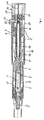
図1には、可変の投薬分を有する自動注射器、すなわち注射のため投与すべき製剤の所望の投薬分をユーザが設定することのできる自動注射器が示されている。製剤は、例えば、インシュリン、成長ホルモン又は骨粗鬆症処方剤のような液体医薬であることが好ましい。図1には、最大投薬分、すなわち、起動されたとき、投与されるであろう、注射器が投与できる最大の製剤投薬分に相応する設定状態にある注射器が示されている。 FIG. 1 shows an auto-injector with variable dosage, ie an auto-injector that allows the user to set the desired dosage of the formulation to be administered for injection. The formulation is preferably a liquid medicament such as, for example, insulin, growth hormone or osteoporosis formulation. FIG. 1 shows a syringe in a set state corresponding to the maximum dosage, ie the maximum formulation dosage the syringe can administer that will be administered when activated.
図5には、注射器の一部分が拡大縮尺にて示されており、明確さを保つため図1にて省略した、注射器の構成要素には参照番号を付してある。1つの実施の形態の第一の例を説明するため、常に、図5を参照する。 In FIG. 5, a portion of the syringe is shown on an enlarged scale, and components of the syringe that are omitted from FIG. 1 for clarity are labeled with reference numerals. Always refer to FIG. 5 to illustrate a first example of one embodiment.
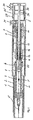
注射器は、第一のハウジングスリーブ1と、共通の中央長手方向軸線Lに沿って第一のハウジングスリーブ1に対して変位可能な第二のハウジングスリーブ2とを実質的に備えるハウジングを有している。第一のハウジングスリーブ1は、第二のハウジングスリーブ2に対する軸方向への摺動案内部を形成する。長手方向軸線Lに沿って前方駆動方向Vに変位可能である、製剤にて充填された容器3がハウジングスリーブ2内に受容されている。前方駆動方向Vを基準として、容器3の前側末端に取り付けられているのは、長手方向軸線Lに沿って前方駆動方向Vを向いた注射カニューレ5である。プランジャ4は、シールを形成する前方駆動方向を基準としてその後側基端にて容器3に隣接している。プランジャ4は、容器の出口に向けて前方駆動方向Vに変位可能であり、投与動作により製剤を容器3から突き出し且つ、その製剤を注射カニューレ5を通して投与する。容器3の変位可能な取り付けは、容器ホルダ6によって実現され、容器3がストッパに対して静止する迄、容器は、前方駆動方向Vにこの容器ホルダ6内に押される。ハウジングスリーブ2は、容器ホルダ6、従って、容器3に対する軸方向直線状案内部を形成する。ハウジングスリーブ2は、容器3を有する容器ホルダ6を取り囲むのみならず、注射カニューレもその先端まで且つ、その先端を超えて取り囲む。ハウジングスリーブ2は針防護部を形成する。
The syringe has a housing substantially comprising a
プランジャロッドよりプランジャ4は前方に駆動される。該プランジャロッドは、投薬分の計量供給係合状態にある、2つのプランジャロッド部分11、12を備えている。該係合状態にあるとき、プランジャロッド部分11は、投薬分の計量供給動作を実行する際、プランジャロッド部分12に対し軸方向に変位する。投薬分の計量供給係合状態は確実係合状態である。第一のプランジャロッド部分11はロッド形状をしており、また、ラム11aと、該ラムに隣接する、ねじ付き部分11bの形態とされた係合部分と、最後に、端部に連結部分11dを有する軸11cとを備えている。プランジャロッド部分11は、前方駆動方向Vにプランジャ4に接触圧力を加えるだけで作用する。プランジャロッド部分11とプランジャ4との間には、圧力接触以外の接続部は存在しない。
The
プランジャロッド部分11は、プランジャロッド部分12を貫通して伸びている。プランジャロッド部分12は、止めスリーブ12bと係合部分12aとにより形成される。係合部分12aは、その前端にてスリーブ12b内に押し込まれる。係合部分12aは、プランジャロッド部分11と投薬分の計量供給係合状態にあり、また、一例として示した実施の形態において、ねじ付き部分11bと螺着係合状態にある。
プランジャロッド11、12は、駆動構造体16内にて前方駆動方向Vに軸方向に変位可能であるよう取り付けられ且つ、かかる動作、すなわち投与動作中、駆動構造体16によって直線状に案内される。末端の直線状案内部は駆動構造体16内に押し込まれたスリーブによって提供される。該スリーブは、摺動動作するとき、プランジャロッド部分12を案内し且つ、ストッパ18を形成する。該ストッパ18は、前方駆動方向Vに向けたプランジャロッド11、12の投与動作を制限する。駆動構造体16とプランジャロッド部分11との間に基端側の直線状案内部が形成される。プランジャロッド部分11とプランジャロッド部分12との間の環状空隙内には投与ばね15が受容される。該投与ばねは、一例として示した実施の形態において、ヘリカルばねである。該ヘリカルばねは、前方駆動方向Vと反対方向に駆動構造体16及びプランジャロッド部分12に支持され、また、一例として示した実施の形態において、その係合部分12aにて前方駆動方向に支持されてプランジャロッド11、12をばね力によって偏倚させる。プランジャロッド11、12は、偏倚した投与ばね15の力に抗して基端側の保持位置に保持され又は妨害され、この位置にあるとき、プランジャロッド部分12は駆動構造体16と解放可能な止め係合状態にある。止め係合状態を実現するため、スリーブ12bはその基端にて外方に幅が広がり、これにより、長手方向軸線Lに対しある角度で傾斜する止め肩部13を形成する。止め肩部13は、幾つかの妨害要素14の後方に係合する。これらの妨害要素は、駆動構造体16のオリフィス内を案内される。このため、これらの妨害要素は長手方向軸線Lに対して横方向に動くことができる。妨害要素14は円筒状ピンであるが、例えば、玉軸受の形態にて提供してもよい。妨害要素14は、止め肩部13による押し付け力により半径方向外方に偏倚される。プランジャロッド11、12が止め位置にあるとき、妨害要素14は軸受ブロック7によってその撓みが阻止される。該軸受ブロックは、駆動構造体16を軸方向に変位するよう案内し、また、妨害要素14は、該軸受ブロックにて受容する軸方向部分を取り囲む。軸受ブロック7はハウジング位置と固定状態に接続される。
The
注射ばね17は、駆動構造体16を容器3に対し前方駆動方向Vに偏倚させる。駆動構造体16は、同様に解放可能である基端側の止め位置にて止め係合状態に妨害される。止め係合状態にあるとき、駆動構造体16は妨害要素20の後方に係合する。妨害要素20は、伝導片22を介してトリガー要素21を作用させることにより、駆動構造体16との止め係合状態を脱し長手方向軸線Lに対して横方向に動くことができる。トリガー要素21は、ハウジングスリーブ1から突き出し、単に起動目的のため内方に押されるトリガーノブである。
The
第二のプランジャロッド部分12は、該第二のプランジャロッド部分がハウジングスリーブ1に対して回転することができないよう駆動構造体16及び軸受ブロック7によって取り付けられる。
The second
駆動構造体16と、プランジャロッド11、12と、2つのばね15、17とを実質的に備える駆動装置は装荷状態にある。この装荷状態にあるとき、駆動構造体16は、ハウジングスリーブ1に対しその基端側の止め位置にて妨害され、また、プランジャロッド11、12は、駆動構造体16に対しその基端側止め位置にて妨害されている。この状態にあるとき、駆動装置が起動されたときに投与されるであろう製剤の投薬分を設定することができる。この製剤の投薬分を設定するためには、基端方向に固定されたプランジャロッド部分12に対するプランジャロッド部分11の軸方向位置を調節する。この調節の結果、プランジャとラム11aとの間の軸方向隙間距離は変化する。プランジャロッド11、12の投与ストロークの軸方向長さは、プランジャロッド11、12及びストッパ18の基端方向止め位置により予め決定されており、この調節による影響を受けない。その代わり、投与ストロークの範囲内にて軸方向隙間距離を調節すれば、プランジャロッド部分11がプランジャ4に押され且つ、該プランジャを前方に駆動するときの移動長さが予め決定される。
The drive device substantially comprising the
図1において、プランジャロッド部分11は、プランジャロッド部分12に対するその最末端側位置にある。この位置において、該プランジャロッド部分は、プランジャロッド11、12がプランジャ4に対する止め位置にあるとき、「零」となる最小距離を有する。この設定状態において、プランジャロッド11、12及びプランジャ4は、投与ストロークの間、最大の共通の移動長さをカバーし、設定可能な最大の製剤の投薬分、すなわち最大投薬分が投与される。
In FIG. 1, the
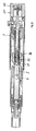
図2には、同様に装荷状態にあるが、「最小投薬分」位置にある注射器が示されている。プランジャロッド部分11は、プランジャロッド部分12に対するその最大の基端側位置にある。この基端側位置にあるとき、ラム11aはプランジャロッド部分12aの断面と当接接触している。プランジャ4とプランジャロッド11、12との間の軸方向隙間距離は、止め位置にてその最大値となり、投与ストロークの過程の間、プランジャロッド11、12がプランジャ4に対して押すときの移動長さは最小である。
FIG. 2 shows the syringe similarly loaded but in the “minimum dose” position. The
注射器は、一回限り使用の設計とされ且つ、注射後、処分される。この注射器は、容器3が最大投薬分を保持する装荷状態にて例えば、製剤を自分自身で投与する人間又は医師のようなユーザに提供される。ユーザは、プランジャロッド11、12自体の長さを設定することにより、所望の製剤投薬分、この意味にて個人的な製剤投薬分を設定する.
ハウジングスリーブ1に対する投薬分の計量供給動作を実行することのできる投薬分の計量供給要素25によって設定が行なわれる。一例として示した実施の形態において、投薬分の計量供給要素25が長手方向軸線Lの回りにて回転動作を実行することができる、すなわち、投薬分の計量供給動作は長手方向軸線Lの回りの回転動作であるように投薬分の計量供給要素はハウジングスリーブ1に固定される。回転動作を伝達するため、投薬分の計量供給要素25は連結要素27によりプランジャロッド11、12と連結され、該投薬分の計量供給要素が長手方向軸線Lの回りにて回転することはない。しかし、プランジャロッド部分11は、連結要素27に対し軸方向に動くことができる。連結要素27は、投薬分の計量供給要素25と接続され、該連結要素が回転することはない。一例として示した実施の形態において、該連結要素は、投薬分の計量供給要素25の長手方向リブの形態をした投薬分の計量供給要素25と一体である。
The syringe is designed for one-time use and is disposed of after injection. This syringe is provided, for example, to a user such as a human or a doctor who administers the formulation himself, with the
Settings are made by means of a
投薬分の計量供給要素25は、そのスリーブ部分に投薬分目盛り26が設けられており、その投薬分単位量は基端から末端まで目盛りが増大する状態に示されている。その投薬分目盛り26により、投薬分の計量供給要素25は、投薬分ディスプレイの第一のディスプレイ要素を構成する。投薬分ディスプレイの第二のディスプレイ要素30は、ばね28によりプランジャロッド部分11の基端に押し付けられ且つ、帽子形状の肩部の形態にて提供される。第二のディスプレイ要素30は、指針31を形成する。該指針の軸方向位置は投薬分目盛り26にて読み取ることができる。この目的のため、投薬分の計量供給要素25は、投薬分の計量供給要素25のスリーブ部分を通して指針31を見ることができるよう投薬分目盛り26の領域内にて透明であり又は完全に透明であることが好ましい。
The
連結要素27は、ディスプレイ要素30の長手方向溝内に係合し、その結果、長手方向軸線の回りにてディスプレイ要素25、30が回転するのは阻止されるが、互いに軸方向に変位可能であるよう接続される。ディスプレイ要素30は、該ディスプレイ要素が回転できないようプランジャロッド部分11の連結部分11d上に位置している。その結果、投薬分の計量供給要素25は、連結要素27及びディスプレイ要素30を介する連結により、剛性な回転配置状態にてプランジャロッド部分11と接続される。
The
製剤を投与するときの手順は、図1ないし図4の一連の図から理解することができる。
装荷状態にあるとき、投与すべき製剤の投薬分は、投薬分の計量供給要素25を回すことで設定される。また、原理上、図1に示した設定状態にて投与される最大投薬分と、図2に示した設定状態にて投与される最小投薬分との間で製剤の各々の投薬分を選ぶことができる。しかし、指針31が投薬分の計量供給要素25のケーシング内面に沿って摺動するとき、指針31は幾つかの別個の拘束位置に掛け止めし、ユーザは、カチッという音によりこりことが知覚可能である。別個のステップにて、この場合、選択可能な指針31の幾つかの拘束位置により製剤の投薬分が設定されることは、実際に所望の製剤の投薬分が設定されるときの確実さを向上させることになる。第二のディスプレイ要素30は、プランジャロッド部分11の軸方向への設定動作も実行するから、プランジャロッド部分11の位置は、目盛り26に直接表示される。
The procedure for administering the formulation can be understood from the series of figures in FIGS.
When in the loaded state, the dosage of the formulation to be administered is set by turning the
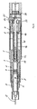
製剤の投薬分が設定され、又は事前に設定されたならば、注射カニューレ5を取り囲むカニューレのキャップを除去し且つ、ハウジングスリーブ2から引っ張り出す。このとき、注射器は注射の準備が整う。注射するためには、注射器をハウジングスリーブ1の領域にて把持し、その末端が注射箇所にある状態にて皮膚に垂直に配置する。次に、ハウジングスリーブ1を前方駆動方向に押して、その結果、ハウジングスリーブはハウジングスリーブ2に対するばね10の力に抗して前方駆動方向Vに移動する。この相対的な動作をする間、ハウジングスリーブ2が内方に動くとき、該ハウジングスリーブは、伝導片22を押して該伝動片が軸方向ストッパに達する迄、トリガー要素21と軸方向に重なり合うようにする。軸方向ストッパは、ハウジングスリーブ1、2の間の相対的な動きを制限する。このとき、注射カニューレ5は、ハウジングスリーブ2のほぼ末端まで突き出している。
Once the dosage of the formulation has been set or preset, the cap of the cannula surrounding the injection cannula 5 is removed and pulled out of the
次のステップにてトリガー要素21を押すことによって駆動装置を起動させる。トリガー要素21は、伝導要素が到達した軸方向位置にて半径方向に変位可能である伝導片22に対し半径方向に押される一方、妨害要素20に対し押される。トリガー要素21が押されるから、妨害要素20は駆動構造体16との止め係合状態から押し出される。止め係合状態が解放されると直ちに、注射ばね17は、駆動構造体16を前方駆動方向Vに駆動する。駆動構造体16は、本来的に軸方向に剛性であり、また、その内部に容器2が受容された容器ホルダ6をそれ自体の前方への動きにより前方駆動方向Vに押す。この前方駆動動作の結果として、注射カニューレ5は、皮膚内に、好ましくは皮膚を通じて突き刺し、製剤を好ましくは皮下的に投与する。
In the next step, the drive device is activated by pressing the
図3には、容器2の前方への駆動動作、従って、注射カニューレ5の注射動作が終了したが、プランジャロッド11、12の投与ストロークは未だ開始していない状態にある注射器が示されている。注射段階後であり且つ、投与段階前の状態にあるとき、その内部を妨害要素14が半径方向に案内される駆動構造体16のオリフィスは凹所8と重なり合う点に到達し、又は、駆動構造体16を取り囲む軸受妨害部7のケーシングの内面に形成された、周方向に伸びる単一の凹所8に到達している。これらは今や撓み可能であり、また、止め肩部13又は複数の止め肩部13の形状は傾斜しているため、妨害要素14は、1つ又は複数の止め肩部13に沿って外方に押され、このため、プランジャロッド部分12は妨害要素14から解放される。プランジャ部分12は、投与ばね15の力によって前方駆動方向Vに動き、また、投薬分の計量供給係合状態によってプランジャロッド部分11を共に駆動する。プランジャロッド11、12が設定された距離に相応する、プランジャ4からの移動長さをカバーし且つ、プランジャ4と圧力接触したならば、該プランジャロッドは、容器2内にてプランジャ4を前方駆動方向Vに投与ストロークの残りの経路に沿って押し、その結果、設定された製剤の投薬分が注射カニューレ5を通じて投与される。
FIG. 3 shows a syringe in which the forward drive operation of the
投与ストロークの間、第二のプランジャロッド部分12は、また、容器3内に動く。このため、その断面の外寸法は、容器3の中空の断面により制限される。このため、細長い容器の場合、金属スリーブ本体はプラスチックスリーブよりも細い肉厚にて同一又はより高強度を提供することができるから、第二のプランジャロッド部分12は、係合部分12aが挿入された金属スリーブ12bの形態にて提供されることが好ましい。
During the dosing stroke, the second
投与ストローク過程の間、ディスプレイ要素30は動いてハウジングスリーブ1の後端面と当接し、このため、プランジャロッド11、12は、ディスプレイ要素30から解放される。
During the dosing stroke process, the
図4には、設定された製剤の投薬分が投与された後で且つ、注射カニューレ5が組織から除去される前の注射器が示されている。注射器が注射箇所から引き離されたとき、ばね10は、ハウジングスリーブが挿入カニューレ5を取り囲み且つ、その先端を超えて突き出す停止位置に到達する迄、ハウジングスリーブ2をハウジングスリーブ1に対し前方駆動方向Vに押す。その最末端位置にてハウジングスリーブ2は係止されて、注射カニューレ5に起因する損傷を防止する。次に、注射器を処分し、また、例えば、製造メーカに戻す。
FIG. 4 shows the syringe after the set dosage of the formulation has been administered and before the injection cannula 5 is removed from the tissue. When the syringe is pulled away from the injection site, the
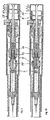
図6には、第二の実施の形態の例に基づく、可変投薬分を有する自動注射器の基端部分が示されている。注射器は、「最大投薬分」の設定状態にて示されている。第一の実施例にて示した実施の形態にて使用されるものと同一の機能を果たす構成要素は同一の参照番号で示されている。別段の説明がない限り、第一の一例としての実施の形態に関して記述した説明は、第二の実施の形態にも当て嵌まる。 FIG. 6 shows the proximal portion of an auto-injector with variable dosage according to the second embodiment example. The syringe is shown in a “maximum dose” setting. Components performing the same functions as those used in the embodiment shown in the first example are indicated by the same reference numerals. Unless stated otherwise, the description given with respect to the first exemplary embodiment also applies to the second embodiment.
一例として示した第二の実施の形態によるプランジャロッドは3つの部分に分かれており、第一のプランジャロッド部分11と、第二のプランジャロッド部分12と、第三のプランジャロッド部分19とから成っている。この場合にも、第一のプランジャロッド部分11は、ラムと、投薬分の計量供給係合状態とする係合部分とを構成する。第一のプランジャロッド部分11は、スリーブであり、そのケーシングの内面に係合部分を有しており、また、その基端におけるラムは、平坦な基部の形態にて提供される。係合部分は、この場合にも、ねじ付き部分の形態にて提供される。第二のプランジャロッド部分12は、円筒状スリーブであり、この場合にも、係合部分12aと、その基端に止め肩部13を有する止めスリーブ12bとを備えている。プランジャロッド部分12は、第一のプランジャロッド部分11を取り囲み且つ、該第一のプランジャロッド部分をその係合部分12aにより、回転させることなく軸方向に直線状に案内する。一方、プランジャロッド部分12は、駆動構造体16内に回転不能に受容される一方、該駆動構造体は、軸受ブロック7によって案内され且つ、回転が阻止される。第三のプランジャロッド部分19は、第一のプランジャロッド部分11との投薬分の計量供給係合状態を確立し、また、一例として示した実施の形態にてねじ付き部分である末端の係合部分19aと、駆動構造体16を軸方向に案内し且つ、その端部が連結部分19cの形態にて提供される基端軸19bとから成っている。第三のプランジャロッド部分19は、長手方向軸線Lの回りにて回転可能である。第三のプランジャロッド部分は、投与ばね15により前方駆動方向Vに偏倚されており、また、投与ばね15は、第三のプランジャロッド部分19の外方に突き出す肩部に支持される。肩部は、前方駆動方向に第二のプランジャロッド部分12の相補的な肩部と当接する。その結果、注射器が起動されたとき、プランジャロッド11、12、19は前方に駆動される。従って、投与ばね15は、1つの実施の形態のこの例においても同様に、最終的に第二のプランジャロッド部分12に支持される。
The plunger rod according to the second embodiment shown as an example is divided into three parts, and consists of a first
第三のプランジャロッド部分19は、ハウジングスリーブ1から後端面を超えて突き出し、また、第一の例として示した実施の形態におけると同一の要領にて、ディスプレイ要素30及び連結要素27を介して投薬分の計量供給要素25と接続される。プランジャロッド11、12、19が止め位置にあるとき、第三のプランジャロッド部分19は回転可能であるが、第三のプランジャロッド部分は、投与ばね15と第二のプランジャロッド部分12の停止肩部との間にて緊密に締め止めされる。このため、プランジャロッド11、12、19が止め位置にあるとき、該第三のプランジャロッド部分は、全ての意図及び目的のため、軸方向に固定されたものとみなすことができる。
The third
第二のディスプレイ要素30は、長手方向軸線Lの回りにてハウジングスリーブ1と螺着係合している。そのねじ付き部分を参照番号32で示し、また、ハウジングスリーブ1のねじ付き部分を参照番号1aで示してある。他方、ディスプレイ要素30は、該ディスプレイ要素は回転できず、軸方向に直線状に案内されるよう、プランジャロッド部分19と接続される。製剤の投薬分は、この場合にも、投薬分の計量供給要素25の投薬分の計量供給回転動作によって設定され且つ、その連結要素27及びディスプレイ要素30によって第三のプランジャロッド部分19に伝達される。投薬分の計量供給動作は、ねじ付き部分19aが第一のプランジャロッド部分11のねじ付き部分及びその軸方向の直線状案内部と投薬分の計量供給係合するから、第一のプランジャロッド11の軸方向への動きに変換される。ディスプレイ要素30は、同時に、ハウジングスリーブ1との螺着係合状態にて軸方向に変位する。第一のプランジャロッド部分11が螺着係合する場合よりもディスプレイ要素30が螺着係合する場合の方が小さいねじが選ばれるため、第一のプランジャロッド部分11の軸方向への変位に比例してディスプレイ要素30の軸方向への変位が減少する。一例として示した第二の実施の形態は、投薬分ディスプレイに関して、プランジャロッド11、12、19の軸方向への変位量が何らかの方法にて増加又は好ましくは減少し且つ、それがディスプレイ要素30、従って指針31の軸方向への変位に変換される様子を示す。
The
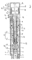
図7には、第三の実施の形態の一例に基づいて、可変投薬分を有する自動注射器の基端部分が示されている。自動注射器は、「最小投薬分」の設定状態にて示されている。
第一の例として示した実施の形態にて示したものと同一の参照番号を使用して、同一の機能を実現する構成要素を示す。その機能に関して、駆動装置は、第一の例による実施の形態に関して説明した駆動装置に相応する。特に、プランジャロッド11、12は、この場合にも、第一のプランジャロッド部分11と、第二のプランジャロッド部分12とから成る2つの部分を備えている。
FIG. 7 shows the proximal portion of an auto-injector with variable dosage according to an example of the third embodiment. The auto-injector is shown in a “minimum dose” setting.
The same reference numerals as those shown in the embodiment shown as the first example are used to indicate the components that realize the same function. In terms of its function, the drive device corresponds to the drive device described with respect to the embodiment according to the first example. In particular, the
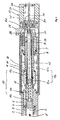
一例として説明した最初の2つの実施の形態による注射器と異なり、第三の実施の形態による一例として説明した自動注射器には、プライミング機構35が設けられている。注射前、このプライミング機構により注射カニューレ5の先端まで製剤を運ぶ構成要素から空気を除去することができるが、これらの構成要素費は図示していない。
Unlike the syringe according to the first two embodiments described as an example, the automatic injector described as an example according to the third embodiment is provided with a
プライミング機構35は、細長いロッドであり且つ、長手方向軸線L上にてプランジャロッド11、12を貫通して伸びている。プランジャロッド部分11、12の双方は、プライミング機構35を同心状に取り囲む。プランジャロッド11、12が止め位置にあるとき、プライミング機構35は、プランジャロッド11、12を貫通して、特に前方駆動方向Vに伸びており、このため、該プライミング機構は、プランジャロッド11、12の前方のその末端によりプランジャ4に作用することができる。しかし、該プライミング機構は、前方駆動方向Vと反対方向にプランジャロッド11、12を貫通して伸びて且つ、該プライミング機構は長手方向軸線Lの回りにて回転するのが阻止され、また、軸方向に動くこともできないようその基端にて投薬分の計量供給要素25と接続されている。第三の実施の形態の例における第一のプランジャロッド部分11は、プライミング機構35が該部分を貫通して伸びるのを可能にし得るようスリーブ形状である点にてのみ、第一の実施例として示した実施の形態のプランジャロッド11、12と相違する。プライミング機構35は、長手方向軸線Lの回りにて回転するのは阻止されるが、第一のプランジャロッド部分11に対し且つ、駆動装置のその他の構成機構に対し前方駆動方向Vに動くことができるように、該機構を直接取り囲む第一のプランジャロッド部分11と接続されている。これと逆に、プランジャロッド部分11は、プライミング機構35に対し軸方向に動いて製剤の投薬分を設定することができる。プライミング機構35は、プランジャロッド11、12に対し且つ、当然に、そのそれぞれの止め位置にて駆動構造体16に対するプライミングストロークを実行することができる。その間、プライミング機構は、プランジャ4に対し押されて、該プランジャを前方駆動方向Vに駆動する。製剤を保持する構成要素内に残るであろう空気を製剤によって確実に押し出すことができるが、この追い出し過程中に投与される製剤が可能な限り少ないようなプライミングストロークの長さ寸法とされている。プライミングストロークは投与ストロークよりも著しく短い。
The
投薬分の計量供給要素25は、製剤の投薬分を設定する投薬分の計量供給要素としてのみならず、プライミング機構35の作動要素としても機能する。プライミング機構35を作動させるため、投薬分の計量供給要素25は、ハウジングスリーブ1に対する投薬分の計量供給動作のみならず、プライミングストロークも実行するようハウジングスリーブ1と接続されている。ハウジングスリーブ21は、その基端にて投薬分の計量供給要素25と接続するための接続部分9を形成する。この接続部分は、投薬分の計量供給要素25を軸方向に案内し、また、該接続部分によって投薬分の計量供給要素25は、互いに離れた軸方向距離だけ隔てられた幾つかの拘束位置に掛け止めすることができる。接続部分9は、拘束凹所を有する拘束部分を形成する。投薬分の計量供給要素25は、合わさる拘束機構、すなわち、一例として示した実施の形態にて拘束耳状突起29を有している。納入された状態のとき、投薬分の計量供給要素25は、拘束位置の最基端側にて接続部分9に掛け止めされている。この拘束位置から、投薬分の計量供給要素は、選択的に、前方駆動方向Vに他の拘束位置の1つまで動くことができる。可聴のカチッという音がユーザに掛け止め動作が生じたことを示す。一例として示した実施の形態において、合計3つの拘束位置が提供される。投薬分の計量供給要素25は、拘束位置の各々からハウジングスリーブ1に対し回転させることができる。
The
投薬分ディスプレイは、プライミング機構35の軸方向位置をも考慮する、すなわち、該投薬分ディスプレイは、プライミングストロークが実行されたかどうか、また、実行されたプライミングストロークの長さも考慮する。この目的のため、投薬分目盛り26は、1回のプライミングストロークによって投与できる最大の製剤投薬分を含むよう拡大する。プライミングストロークが実行されているとき、第一の一例としての実施の形態におけるように第一のプランジャロッド部分11と接続された指針31を構成するディスプレイ要素30は、ハウジングスリーブ1に対し軸方向に静止したままである。しかし、プライミングストロークの間、投薬分目盛り26は、ハウジングスリーブ1及びディスプレイ要素30に対し前方駆動方向Vに向けて軸方向に動き、このため、これに応じて投薬分目盛り26における指針31の位置は変化する。投薬分の計量供給要素25が軸方向への圧力のため、その最基端側の拘束位置からその最末端側の拘束位置まで動いて、プライミング機構35がその可能な最大プライミングストロークを実行するとき、投薬分の計量供給要素25、従ってその投薬分目盛り26はディスプレイ要素30及びその指針31に対し前方駆動方向Vに動き、プライミングストロークが実行された後に残る残留投薬分が表示される。一例として示した実施の形態において、可能な最大のプライミングストロークを実行した後、依然として図示した「最小投薬分」の設定状態にある容器の中身の半分を注射のため投与することができる。実際の適用例において、プライミング機構35が作動された後、すなわちプライミングストロークが実行された後に、製剤は設定される。しかし、この順序は、何らの支障なく逆にすることができる。
The dosage display also considers the axial position of the
図8ないし図11には、同様にプライミング機構35が装着された、第四の実施の形態による一例に基づく、可変投薬分を有する自動注射器が示されている。第四の一例としての実施の形態は、第二の一例としての実施の形態と同一の要領にて投薬分ディスプレイが設けられるが、プライミング機構35を備えるから、プライミング機構35が存在する点にて第三の一例としての実施の形態と相違する。図8ないし図10には、プライミング機構35が異なる軸方向位置にあり、及びプランジャロッド11、12が2つの限界的な設定状態にある注射器が示されている。図11には、より大きい縮尺にて図10に示した設定状態にある注射器の基端部分が示されている。図8ないし図10を説明するとき、常に、図11を参照する。
FIGS. 8 to 11 show an auto-injector with variable dosage, based on an example according to a fourth embodiment, which is likewise fitted with a
プランジャロッド11,12は、この場合にも、2つの部分から成っており、第二のプランジャロッド部分12は、第一の及び第三の一例としての実施の形態におけるものと同一である。第一のプランジャロッド部分11は、ラム11aと、第三の一例としての実施の形態に関して説明したように形成された係合部11bとから成っている。その軸方向の長さは、止め位置にあるとき、図8に示した最小投薬分の設定状態から該プランジャロッド部分がプランジャ4と接触する、図10に示した最大投薬分の設定状態まで、その第二のプランジャロッド部分12と投薬分の計量供給係合状態にて変位するのに丁度、必要な長さである。第二のプランジャロッド部分12は、この場合にも、第一のプランジャロッド部分11が前方駆動方向Vに且つ、その反対方向に軸方向に変位するのを制限するストッパを形成する。第一のプランジャロッド部分11は、その係合部分11bにて薄いスリーブであり、また、第三の一例としての実施の形態の場合と同様に、該第一のプランジャロッド部分は回転できないが、軸方向には変位可能であるように、プライミング機構35と接続されている。一方、プライミング機構35は、該プライミング機構が回転できず、従って、この場合にも、投薬分の計量供給要素25とプランジャロッド11、12との間の連結部を形成するように投薬分の計量供給要素25と接続されている。
The
第三の一例としての実施の形態と相違して、ディスプレイ要素30は、プライミング機構35に対し軸方向に変位可能であり且つ、プライミング機構35によって軸方向に案内されるが、回転することはできない。
Unlike the third exemplary embodiment, the
プライミング機構35の案内部分は参照番号36で示され、また、ディスプレイ要素30の案内部分は参照番号33で示されている。ハウジングスリーブ1との螺着係合状態は箇所1a、32に在る。このため、第四の一例としての実施の形態による投薬分ディスプレイは、第二の一例としての実施の形態(図6)の投薬分ディスプレイと相応し、この場合、プライミング機構35は、この点に関して第二の一例としての実施の形態による第三のプランジャロッド部分19の機能を果たす。
The guiding portion of the
図8には、注射中に投与可能である最小投薬分が設定され、未だプライミングされていない状態の注射器が示されている。プライミング目的のため、ユーザは、投薬分の計量供給要素を接続部分9によって前方駆動方向Vに図示した最基端側の拘束位置から他の拘束位置の1つに押し込む。この操作の結果としてプライミング機構35は拘束位置により予め画成された移動経路だけ前方駆動方向Vに動き、また、プランジャ4を前方駆動方向Vに駆動し、このため、そのシステム内に残留する全ての空気は製剤によって押し出される。
FIG. 8 shows the syringe with the minimum dose that can be administered during injection set and not yet primed. For priming purposes, the user pushes the dosing metering element by means of the connecting
図9には、最小投薬分に設定され、可能な最大のプライミングストロークが実行された後の注射器が示されている。この状態にあるとき、投薬分ディスプレイは、注射する間、投与可能な最大製剤投薬分の半分が投与されることを表示する。 FIG. 9 shows the syringe after the minimum dose has been set and the maximum possible priming stroke has been performed. When in this state, the dosage display will indicate that half of the maximum dosage that can be administered is administered during the injection.
図10には、「最大投薬分」の設定状態にあり、また、可能な最大のプライミングストロークを実行した後の注射器が示されている。投薬分ディスプレイは、注射器がこの状態にて起動されたならば投与可能である製剤の最大投薬分が投与されることを表示する。 FIG. 10 shows the syringe in a “maximum dose” setting and after performing the maximum possible priming stroke. The dosage display indicates that the maximum dosage of the formulation that can be administered if the syringe is activated in this state is to be administered.
一例として説明した全ての実施の形態において、注射は、第一の例による実施の形態に関して説明したものと同一の要領にて行われる。 In all embodiments described as an example, the injection is performed in the same manner as described for the embodiment according to the first example.
1 ハウジングスリーブ
1a ねじ付き部分
2 ハウジングスリーブ、針防護部
3 容器
4 プランジャ
5 注射カニューレ
6 容器ホルダ
7 軸受ブロック
8 凹所
9 接続部分、拘束部分
10 ばね
11 第一のプランジャロッド部分
11a ラム
11b 係合部、ねじ付き部分
11c 軸
11d 連結部分
12 第二のプランジャロッド部分
12a 係合部、ねじ付きナット
12b 止めスリーブ
13 止め肩部
14 妨害要素、円筒状ピン
15 投与ばね
16 駆動構造体
17 注射ばね
18 投与ストッパ
19 第三のプランジャロッド部分
19a 係合部分
19b 軸
19c 連結部分
20 妨害要素
21 起動要素、ノブ
22 伝導片
25 投薬分の計量供給要素、ディスプレイ要素
26 投薬分目盛り
27 連結要素
28 ばね
29 拘束機構、拘束耳状突起
30 ディスプレイ要素
31 指針
32 係合部分、ねじ付き部分
33 案内部分
35 プライミング機構、プライミングロッド
36 案内部分
DESCRIPTION OF
Claims (49)
b)製剤のリザーバ(3)と、
c)リザーバ(3)内にて前方駆動方向(V)に軸方向に変位可能であり、また、前方駆動方向(V)に投与ストロークを実行し、製剤を投与するプランジャと、
d)前方駆動方向(V)に変位可能であり且つ、プランジャ(4)に作用して前方駆動方向(V)へのプライミングストロークを許容し、空気をリザーバ(3)から除去するプライミング機構(35)とを備える、注射可能な製剤を投与する投与装置において、
e)プライミング機構(35)は、プライミングストロークのため、プランジャロッド(11、12)に対し前方駆動方向(V)に動くことができることを特徴とする、注射可能な製剤を投与する投与装置。 a) the housing (1);
b) formulation reservoir (3);
c) a plunger that is axially displaceable in the forward drive direction (V) within the reservoir (3), and that performs a dosing stroke in the forward drive direction (V) to administer the formulation;
d) A priming mechanism (35) that is displaceable in the forward drive direction (V) and that acts on the plunger (4) to allow a priming stroke in the forward drive direction (V) and remove air from the reservoir (3). An administration device for administering an injectable formulation comprising:
e) Dosing device for administering an injectable formulation, characterized in that the priming mechanism (35) can move in the forward drive direction (V) relative to the plunger rod (11, 12) due to the priming stroke.
リザーバを取り付ける軸方向に変位可能な構造体(16)とを備え、リザーバは、前方駆動方向に動くことができ、又は解放可能な止め係合状態にて注射ばね(17)の力に抗して止め位置にて妨害されることが好ましく、また、止め係合状態が解放されたとき、リザーバ(3)及び注射カニューレ(5)は、前方駆動方向(V)に駆動するようにした、装置。 19. The device according to claim 18, wherein the injection cannula (5) faces the forward drive direction (V) connected to a reservoir (3) that is displaceable in the forward drive direction (V).
An axially displaceable structure (16) for mounting the reservoir, the reservoir being movable in the forward drive direction or resisting the force of the injection spring (17) in a releasable stop engagement. Preferably in the stop position, and when the stop engagement is released, the reservoir (3) and the injection cannula (5) are driven in the forward drive direction (V). .
b)製剤容器(3)と、
c)製剤容器(3)内にて前方駆動方向(V)に軸方向に変位可能なプランジャ(4)と、
d)製剤を投与するため前方駆動方向(V)への投与ストロークを実行するプランジャロッド(11、12;11、12、19)と、
e)前方駆動方向(V)にプランジャロッド(11、12;11、12、19)に作用する投与ばね(15)とを備え、
f)プランジャロッド(11、12;11、12、19)は、止め位置にて投与ばね(15)の力に抗して解放可能な止め係合状態に係止される、自動注射器において、
g)投薬分の計量供給要素(25)は、該要素が製剤の投薬分を設定し得るよう変位可能であるようにハウジング(1)に配備され、
h)投薬分の計量供給要素は、投薬分の計量供給係合状態によりプランジャロッド(11、12;11、12、19)と連結され、投薬分の計量供給要素(25)の投薬分の計量供給動作により、止め係合状態が優勢であるとき、プランジャロッド(11、12;11、12、19)又はプランジャロッドのストッパが軸方向に変位するようにしたことを特徴とする、自動注射器。 a) the housing (1);
b) Formulation container (3);
c) a plunger (4) that is axially displaceable in the forward drive direction (V) within the formulation container (3);
d) Plunger rods (11, 12; 11, 12, 19) that perform a dosing stroke in the forward drive direction (V) to administer the formulation;
e) a dosing spring (15) acting on the plunger rod (11, 12; 11, 12, 19) in the forward drive direction (V),
f) In an automatic syringe, the plunger rod (11, 12; 11, 12, 19) is locked in a releasable stop engagement against the force of the dosing spring (15) in the stop position,
g) the dosage metering element (25) is arranged in the housing (1) such that the element is displaceable to set the dosage of the formulation;
h) The dosage metering element is connected to the plunger rod (11, 12; 11, 12, 19) by the dosage metering engagement, and the dosage metering element (25) is metered An automatic injector characterized in that the plunger rod (11, 12; 11, 12, 19) or the stopper of the plunger rod is displaced in the axial direction when the stop engagement state is dominant by the feeding operation.
49. Automatic syringe according to claim 44, characterized in that the dosage metering element (25) constitutes one of the display elements (25, 30). .
Applications Claiming Priority (3)
| Application Number | Priority Date | Filing Date | Title |
|---|---|---|---|
| DE10351597A DE10351597A1 (en) | 2003-11-05 | 2003-11-05 | Device and autoinjector for administration of an injectable product, useful in drug administration, e.g. for intravenous injection, comprises a housing, a product reservoir, piston, priming mechanism and metering element |
| DE10351596A DE10351596B4 (en) | 2003-11-05 | 2003-11-05 | Autoinjector with variable dose |
| PCT/CH2004/000653 WO2005044346A2 (en) | 2003-11-05 | 2004-10-29 | Device for the administration of an injectable product |
Related Child Applications (1)
| Application Number | Title | Priority Date | Filing Date |
|---|---|---|---|
| JP2010001900A Division JP2010104804A (en) | 2003-11-05 | 2010-01-07 | Device for administration of injectable drug product |
Publications (1)
| Publication Number | Publication Date |
|---|---|
| JP2007509726A true JP2007509726A (en) | 2007-04-19 |
Family
ID=34575416
Family Applications (2)
| Application Number | Title | Priority Date | Filing Date |
|---|---|---|---|
| JP2006538629A Pending JP2007509726A (en) | 2003-11-05 | 2004-10-29 | Injection device for injectable preparations |
| JP2010001900A Withdrawn JP2010104804A (en) | 2003-11-05 | 2010-01-07 | Device for administration of injectable drug product |
Family Applications After (1)
| Application Number | Title | Priority Date | Filing Date |
|---|---|---|---|
| JP2010001900A Withdrawn JP2010104804A (en) | 2003-11-05 | 2010-01-07 | Device for administration of injectable drug product |
Country Status (9)
| Country | Link |
|---|---|
| US (1) | US20060270985A1 (en) |
| EP (2) | EP1684831B1 (en) |
| JP (2) | JP2007509726A (en) |
| CN (2) | CN100591375C (en) |
| AT (1) | ATE454911T1 (en) |
| AU (2) | AU2004286736B2 (en) |
| DE (3) | DE10351596B4 (en) |
| DK (1) | DK1684831T3 (en) |
| WO (1) | WO2005044346A2 (en) |
Cited By (8)
| Publication number | Priority date | Publication date | Assignee | Title |
|---|---|---|---|---|
| JP2012502766A (en) * | 2008-09-18 | 2012-02-02 | ベクトン・ディキンソン・アンド・カンパニー | Medical syringe with slidable sleeve activation |
| JP2012528620A (en) * | 2009-06-01 | 2012-11-15 | サノフィ−アベンティス・ドイチュラント・ゲゼルシャフト・ミット・ベシュレンクテル・ハフツング | Dose setting mechanism for priming drug delivery devices |
| JP2012528627A (en) * | 2009-06-01 | 2012-11-15 | サノフィ−アベンティス・ドイチュラント・ゲゼルシャフト・ミット・ベシュレンクテル・ハフツング | Dose setting mechanism for priming drug delivery devices |
| JP2014527887A (en) * | 2011-09-29 | 2014-10-23 | サノフィ−アベンティス・ドイチュラント・ゲゼルシャフト・ミット・ベシュレンクテル・ハフツング | Drug delivery device and method for drug delivery device |
| JP2016524973A (en) * | 2013-07-17 | 2016-08-22 | サノフイ | Assembly for drug delivery device and method of operation thereof |
| JP2016539741A (en) * | 2013-12-13 | 2016-12-22 | オーウェン マンフォード リミテッドOwen Mumford Limited | Dose selectable injection device |
| JP2018502653A (en) * | 2015-01-21 | 2018-02-01 | アンタレス・ファーマ・インコーポレーテッド | Infusion device with variable dosage |
| JP2021514757A (en) * | 2018-03-01 | 2021-06-17 | サノフイSanofi | Injection device with dose size adjuster |
Families Citing this family (61)
| Publication number | Priority date | Publication date | Assignee | Title |
|---|---|---|---|---|
| US9486581B2 (en) * | 2002-09-11 | 2016-11-08 | Becton, Dickinson And Company | Injector device with force lock-out and injection rate limiting mechanisms |
| DE102004004310A1 (en) * | 2004-01-28 | 2005-08-18 | Tecpharma Licensing Ag | Injection device with lockable dosing member |
| JP2007537800A (en) * | 2004-05-25 | 2007-12-27 | テクファーマ・ライセンシング・アクチェンゲゼルシャフト | Dosing device |
| DE102005018305A1 (en) * | 2004-05-25 | 2005-12-22 | Tecpharma Licensing Ag | Dosing unit comprises a dose-adjusting unit, which is rotated to adjust the dose, and a graduated scale |
| EP1909871B2 (en) | 2005-07-27 | 2014-02-26 | Novo Nordisk A/S | Syringe device with a dose limiting mechanism and an additional safety mechanism |
| ES2361563T5 (en) | 2005-07-27 | 2016-03-22 | Novo Nordisk A/S | Dosing mechanism for an injection device to limit a dose adjustment that corresponds to the amount of medication remaining |
| GB2433032A (en) | 2005-12-08 | 2007-06-13 | Owen Mumford Ltd | Syringe with dose adjustment means |
| DE102007060131A1 (en) * | 2007-12-13 | 2009-06-25 | Technische Universität Dresden | Explanted organ's vessel connection filling method for medical field, involves continuously emptying dosage device and simultaneously withdrawing hose from vessel connection as long as vessel connection is completely filled |
| US11273261B2 (en) | 2008-01-28 | 2022-03-15 | Novo Nordisk A/S | Injection device for performing medical injections |
| CA3070644C (en) | 2008-05-20 | 2022-09-13 | Avant Medical Corp. | Autoinjector system |
| US8177749B2 (en) | 2008-05-20 | 2012-05-15 | Avant Medical Corp. | Cassette for a hidden injection needle |
| US8052645B2 (en) | 2008-07-23 | 2011-11-08 | Avant Medical Corp. | System and method for an injection using a syringe needle |
| WO2009150071A1 (en) * | 2008-06-11 | 2009-12-17 | Shl Group Ab | Medicament delivery device |
| DE102008037310B4 (en) | 2008-08-11 | 2023-11-16 | Ypsomed Ag | Automatic injection device for administering a fixed dose |
| ES2625488T3 (en) * | 2008-09-18 | 2017-07-19 | Becton, Dickinson And Company | Medical injector with dose button activation for automatic reconstitution |
| EP2193817A1 (en) * | 2008-12-02 | 2010-06-09 | Sanofi-Aventis Deutschland GmbH | Drive assembly suitable for use in a medication delivery device and medication delivery device |
| GB0823693D0 (en) | 2008-12-31 | 2009-02-04 | Owen Mumford Ltd | Autoinjector |
| US9463283B2 (en) | 2009-06-01 | 2016-10-11 | Sanofi-Aventis Deutschland Gmbh | Dosing mechanism for a drug deliver device |
| US8974423B2 (en) * | 2009-06-01 | 2015-03-10 | Sanofi-Aventis Deutschland Gmbh | Resettable drug delivery device |
| US9199040B2 (en) | 2009-06-01 | 2015-12-01 | Sanofi-Aventis Deutschland Gmbh | Drug delivery device last dose lock-out mechanism |
| US9457150B2 (en) | 2009-06-01 | 2016-10-04 | Sanofi-Aventis Deutschland Gmbh | Biasing mechanism for a drug delivery device |
| US9108007B2 (en) | 2009-06-01 | 2015-08-18 | Sanofi-Aventis Deutschland Gmbh | Spindle and bearing combination and drug delivery device |
| US9950116B2 (en) | 2009-06-01 | 2018-04-24 | Sanofi-Aventis Deutschland Gmbh | Dose setting mechanism for priming a drug delivery device |
| US9125994B2 (en) | 2009-06-01 | 2015-09-08 | Sanofi—Aventis Deutschland GmbH | Drug delivery device with dose dial sleeve rotational stop |
| US8728043B2 (en) | 2009-06-01 | 2014-05-20 | Sanofi-Aventis Deutschland Gmbh | Drive mechanism for a drug delivery device |
| US8672896B2 (en) | 2009-06-01 | 2014-03-18 | Sanofi-Aventis Deutschland Gmbh | Inner housing for a drug delivery device |
| US9345840B2 (en) | 2009-06-01 | 2016-05-24 | Sanofi-Aventis Deutschland Gmbh | Drug delivery dose setting mechanism with variable maximum dose |
| US10034982B2 (en) | 2009-06-01 | 2018-07-31 | Sanofi-Aventis Deutschland Gmbh | Spindle for a drug delivery device |
| US8257319B2 (en) | 2009-06-01 | 2012-09-04 | Sanofi-Aventis Deutschland Gmbh | Drug delivery device inner housing having helical spline |
| US9623187B2 (en) | 2009-06-01 | 2017-04-18 | Sanofi-Aventis Deutschland Gmbh | Resettable drug delivery device |
| SG10201912277VA (en) | 2009-10-16 | 2020-02-27 | Janssen Biotech Inc | Palm activated drug delivery device |
| US9233213B2 (en) | 2009-10-16 | 2016-01-12 | Janssen Biotech, Inc. | Palm activated drug delivery device |
| DE102009053154A1 (en) * | 2009-11-06 | 2011-05-12 | Tecpharma Licensing Ag | Administration device e.g. autoinjector for administrating insulin, has actuating element releasing blocking element, and driven element movable around priming stroke to discharge condition by storage unit when block element is released |
| US8986259B2 (en) * | 2010-03-31 | 2015-03-24 | Sanofi-Aventis Deutschland Gmbh | Piston rod assembly for a drug delivery device |
| JP5828886B2 (en) * | 2010-04-09 | 2015-12-09 | サノフィ−アベンティス・ドイチュラント・ゲゼルシャフト・ミット・ベシュレンクテル・ハフツング | Coded cap for use with drug delivery devices |
| EP2588173B1 (en) | 2010-07-02 | 2015-10-07 | Sanofi-Aventis Deutschland GmbH | Safety device for a pre-filled syringe and injection device |
| EP2468330A1 (en) | 2010-12-21 | 2012-06-27 | Sanofi-Aventis Deutschland GmbH | Auto-injector |
| WO2012145685A1 (en) | 2011-04-20 | 2012-10-26 | Amgen Inc. | Autoinjector apparatus |
| US9033934B2 (en) * | 2011-09-27 | 2015-05-19 | Shl Group Ab | Medical delivery device with an initial locked state, intermediate priming state and a medicament delivery state |
| KR101680437B1 (en) * | 2011-10-17 | 2016-11-28 | 에스에이치엘 그룹 에이비 | Medicament delivery device |
| US9827380B2 (en) * | 2011-12-15 | 2017-11-28 | Shl Group Ab | Cap assembly |
| EP2830685B1 (en) * | 2012-03-30 | 2017-05-31 | Tecpharma Licensing AG | Injection device with a dose display element displaceable relative to a housing. |
| USD898908S1 (en) | 2012-04-20 | 2020-10-13 | Amgen Inc. | Pharmaceutical product cassette for an injection device |
| USD808010S1 (en) | 2012-04-20 | 2018-01-16 | Amgen Inc. | Injection device |
| EP2692376B1 (en) * | 2012-08-01 | 2019-04-03 | TecPharma Licensing AG | Injection device with helical or spiral dose scale |
| TWI580451B (en) | 2013-03-15 | 2017-05-01 | 安美基公司 | Cassette for an injector and method of using an autoinjector apparatus having an autoinjector and a cassette |
| TWI614041B (en) | 2013-03-15 | 2018-02-11 | 安美基公司 | Cassette for an injector |
| CA2921927A1 (en) | 2013-08-19 | 2015-02-26 | Dr. Reddy's Laboratories, Ltd. | Selectable single dose auto-injector and methods of making and using same |
| DK3125973T3 (en) * | 2014-03-31 | 2018-06-18 | Sanofi Aventis Deutschland | PEN-TYPE DEVICE FOR INJECTION OF MEDICINAL PRODUCTS WITH SPECIFIC DOSAGE SCALE AND DOSAGE DISPLAY WINDOW INCLUDING AN OPTICAL FILTER FOR MEANING VIEW OF SET DOSAGE VALUE |
| US20170143902A1 (en) * | 2014-06-27 | 2017-05-25 | Novo Nordisk A/S | Autoinjector having needle shield triggering |
| GB2532300B (en) * | 2014-09-30 | 2018-09-19 | Owen Mumford Ltd | Injection devices |
| GB2541227A (en) * | 2015-08-13 | 2017-02-15 | Owen Mumford Ltd | Injector Device |
| US11200298B2 (en) * | 2016-03-15 | 2021-12-14 | Amgen Inc. | Reducing probability of glass breakage in drug delivery devices |
| EP3576822B1 (en) | 2017-02-03 | 2021-12-08 | Norton Healthcare Limited | Assembly for a medication delivery device and medication delivery device comprising such an assembly |
| US11771836B2 (en) | 2017-02-03 | 2023-10-03 | Norton Healthcare Limited | Assembly for a medication delivery device and medication delivery device |
| US11376367B2 (en) | 2017-02-03 | 2022-07-05 | Norton Healthcare Limited | Assembly for a medication delivery device and medication delivery device |
| EP3576819B1 (en) | 2017-02-03 | 2023-08-16 | Norton Healthcare Limited | Assembly for a medication delivery device and medication delivery device |
| CN107314088B (en) * | 2017-07-11 | 2023-05-02 | 宜昌长机科技有限责任公司 | Variable-transmission-ratio backlash-free positioning rack pair device and operation method |
| CA3083999A1 (en) | 2017-12-13 | 2019-06-20 | Regeneron Pharmaceuticals, Inc. | Devices and methods for precision dose delivery |
| GB2577538B (en) * | 2018-09-28 | 2021-10-13 | Owen Mumford Ltd | Injection device fill volume management |
| JP2022535558A (en) | 2019-06-05 | 2022-08-09 | リジェネロン・ファーマシューティカルズ・インコーポレイテッド | Device for precise dose delivery |
Citations (8)
| Publication number | Priority date | Publication date | Assignee | Title |
|---|---|---|---|---|
| JPS63139563A (en) * | 1986-11-14 | 1988-06-11 | ヴィルヘルム・ハーゼルマイヤー・ゲー・エム・ベー・ハー・ウント・コンパニ | Syringe |
| JPH03503129A (en) * | 1988-02-10 | 1991-07-18 | デー・セー・ペー・アー・エフ・1988・アー/エス | Dosage meter for dispensing multiple measured quantities of liquids such as insulin preparations from cartridges |
| JPH062163B2 (en) * | 1987-05-08 | 1994-01-12 | ヴィルヘルム ハゼルマイヤー ゲー・エム・ベー・ハー+ツェー・オー | Injection device with cocking element and second setting element |
| US5320609A (en) * | 1992-12-07 | 1994-06-14 | Habley Medical Technology Corporation | Automatic pharmaceutical dispensing syringe |
| JPH11104240A (en) * | 1997-08-11 | 1999-04-20 | Becton Dickinson & Co | Medicine feeding pen |
| JPH11313888A (en) * | 1998-02-20 | 1999-11-16 | Becton Dickinson & Co | Chemical feed-out pen |
| JP2002541929A (en) * | 1999-04-16 | 2002-12-10 | ベクトン・ディキンソン・アンド・カンパニー | Pen-type syringe with automatic compounding function |
| WO2003008023A1 (en) * | 2001-07-16 | 2003-01-30 | Eli Lilly And Company | Medication dispensing apparatus configured for rotate to prime and pull/push to inject functionality |
Family Cites Families (22)
| Publication number | Priority date | Publication date | Assignee | Title |
|---|---|---|---|---|
| US4064879A (en) * | 1976-04-06 | 1977-12-27 | Metatech Corporation | Pressure-indicating syringe |
| US4031893A (en) | 1976-05-14 | 1977-06-28 | Survival Technology, Inc. | Hypodermic injection device having means for varying the medicament capacity thereof |
| DE3028432A1 (en) * | 1980-07-26 | 1982-03-04 | Günter Dr.med. 8671 Selbitz Reitz | Injection syringe - with concentric rings on holder for attachment of all sizes of syringe cylinder |
| DE3030239C2 (en) * | 1980-08-09 | 1982-09-02 | Heinrich Wilhelm 4803 Steinhagen Schramm | Injection gun |
| AU573369B2 (en) * | 1984-07-31 | 1988-06-02 | N.J. Phillips Pty. Limited | A rumen injector |
| DD253572A1 (en) * | 1986-11-13 | 1988-01-27 | Medizin Labortechnik Veb K | INJECTION DEVICE WITH MEDICATION DEPOT |
| US5226895A (en) * | 1989-06-05 | 1993-07-13 | Eli Lilly And Company | Multiple dose injection pen |
| US5147309A (en) * | 1991-10-22 | 1992-09-15 | Biosafety Systems, Inc. | Apparatus for priming a hypodermic needle with hazardous fluid |
| DE4206300A1 (en) * | 1991-11-29 | 1993-06-03 | Sergej Michailovic Masurik | INJECTION SYRINGE |
| GB9310163D0 (en) * | 1993-05-18 | 1993-06-30 | Owen Mumford Ltd | Improvements relating to injection devices |
| GB9316692D0 (en) * | 1993-08-11 | 1993-09-29 | Smithkline Beecham Plc | Novel device |
| US5514097A (en) * | 1994-02-14 | 1996-05-07 | Genentech, Inc. | Self administered injection pen apparatus and method |
| DE19822031C2 (en) * | 1998-05-15 | 2000-03-23 | Disetronic Licensing Ag | Auto injection device |
| DE19900827C1 (en) * | 1999-01-12 | 2000-08-17 | Disetronic Licensing Ag | Device for the dosed administration of an injectable product |
| JP4290366B2 (en) * | 1999-08-05 | 2009-07-01 | ベクトン・ディキンソン・アンド・カンパニー | Drug delivery pen |
| DE19945397C2 (en) * | 1999-09-22 | 2001-07-19 | Disetronic Licensing Ag | Device for the dosed administration of an injectable product |
| GB2375965B (en) * | 2000-01-28 | 2004-09-01 | Novo Nordisk As | A dose setting limiter |
| DE10047637A1 (en) * | 2000-09-26 | 2002-04-25 | Disetronic Licensing Ag | Device for administering an injectable product |
| JP4283545B2 (en) * | 2001-05-16 | 2009-06-24 | イーライ リリー アンド カンパニー | Drug injection device with simplified reset drive assembly |
| WO2003004080A1 (en) * | 2001-07-05 | 2003-01-16 | Akzo Nobel N.V. | Syringe for the injection of a medicament |
| WO2004028598A1 (en) * | 2002-09-24 | 2004-04-08 | Shl Medical Ab | Injecting device |
| US20060069355A1 (en) * | 2002-10-15 | 2006-03-30 | Jared Alden Judson And Kenneth Alan Ritsher | Medication dispensing apparatus with squeezable actuator |
-
2003
- 2003-11-05 DE DE10351596A patent/DE10351596B4/en not_active Expired - Fee Related
- 2003-11-05 DE DE10351597A patent/DE10351597A1/en not_active Withdrawn
-
2004
- 2004-10-29 DK DK04789821.8T patent/DK1684831T3/en active
- 2004-10-29 JP JP2006538629A patent/JP2007509726A/en active Pending
- 2004-10-29 CN CN200480039873A patent/CN100591375C/en not_active Expired - Fee Related
- 2004-10-29 AU AU2004286736A patent/AU2004286736B2/en not_active Ceased
- 2004-10-29 WO PCT/CH2004/000653 patent/WO2005044346A2/en active Application Filing
- 2004-10-29 CN CN201010003566A patent/CN101797410A/en active Pending
- 2004-10-29 AT AT04789821T patent/ATE454911T1/en not_active IP Right Cessation
- 2004-10-29 DE DE502004010647T patent/DE502004010647D1/en active Active
- 2004-10-29 EP EP04789821A patent/EP1684831B1/en not_active Not-in-force
- 2004-10-29 EP EP10150282A patent/EP2246083A1/en not_active Withdrawn
-
2006
- 2006-05-04 US US11/417,519 patent/US20060270985A1/en not_active Abandoned
-
2009
- 2009-01-15 AU AU2009200170A patent/AU2009200170A1/en not_active Abandoned
-
2010
- 2010-01-07 JP JP2010001900A patent/JP2010104804A/en not_active Withdrawn
Patent Citations (8)
| Publication number | Priority date | Publication date | Assignee | Title |
|---|---|---|---|---|
| JPS63139563A (en) * | 1986-11-14 | 1988-06-11 | ヴィルヘルム・ハーゼルマイヤー・ゲー・エム・ベー・ハー・ウント・コンパニ | Syringe |
| JPH062163B2 (en) * | 1987-05-08 | 1994-01-12 | ヴィルヘルム ハゼルマイヤー ゲー・エム・ベー・ハー+ツェー・オー | Injection device with cocking element and second setting element |
| JPH03503129A (en) * | 1988-02-10 | 1991-07-18 | デー・セー・ペー・アー・エフ・1988・アー/エス | Dosage meter for dispensing multiple measured quantities of liquids such as insulin preparations from cartridges |
| US5320609A (en) * | 1992-12-07 | 1994-06-14 | Habley Medical Technology Corporation | Automatic pharmaceutical dispensing syringe |
| JPH11104240A (en) * | 1997-08-11 | 1999-04-20 | Becton Dickinson & Co | Medicine feeding pen |
| JPH11313888A (en) * | 1998-02-20 | 1999-11-16 | Becton Dickinson & Co | Chemical feed-out pen |
| JP2002541929A (en) * | 1999-04-16 | 2002-12-10 | ベクトン・ディキンソン・アンド・カンパニー | Pen-type syringe with automatic compounding function |
| WO2003008023A1 (en) * | 2001-07-16 | 2003-01-30 | Eli Lilly And Company | Medication dispensing apparatus configured for rotate to prime and pull/push to inject functionality |
Cited By (10)
| Publication number | Priority date | Publication date | Assignee | Title |
|---|---|---|---|---|
| JP2012502766A (en) * | 2008-09-18 | 2012-02-02 | ベクトン・ディキンソン・アンド・カンパニー | Medical syringe with slidable sleeve activation |
| JP2012528620A (en) * | 2009-06-01 | 2012-11-15 | サノフィ−アベンティス・ドイチュラント・ゲゼルシャフト・ミット・ベシュレンクテル・ハフツング | Dose setting mechanism for priming drug delivery devices |
| JP2012528627A (en) * | 2009-06-01 | 2012-11-15 | サノフィ−アベンティス・ドイチュラント・ゲゼルシャフト・ミット・ベシュレンクテル・ハフツング | Dose setting mechanism for priming drug delivery devices |
| JP2014527887A (en) * | 2011-09-29 | 2014-10-23 | サノフィ−アベンティス・ドイチュラント・ゲゼルシャフト・ミット・ベシュレンクテル・ハフツング | Drug delivery device and method for drug delivery device |
| JP2016524973A (en) * | 2013-07-17 | 2016-08-22 | サノフイ | Assembly for drug delivery device and method of operation thereof |
| JP2016539741A (en) * | 2013-12-13 | 2016-12-22 | オーウェン マンフォード リミテッドOwen Mumford Limited | Dose selectable injection device |
| JP2018502653A (en) * | 2015-01-21 | 2018-02-01 | アンタレス・ファーマ・インコーポレーテッド | Infusion device with variable dosage |
| US10661014B2 (en) | 2015-01-21 | 2020-05-26 | Antares Pharma, Inc. | Injection device having variable dosing |
| JP2021514757A (en) * | 2018-03-01 | 2021-06-17 | サノフイSanofi | Injection device with dose size adjuster |
| US11865318B2 (en) | 2018-03-01 | 2024-01-09 | Sanofi | Injection device with dose size adjuster |
Also Published As
| Publication number | Publication date |
|---|---|
| AU2004286736B2 (en) | 2009-02-19 |
| CN101797410A (en) | 2010-08-11 |
| DK1684831T3 (en) | 2010-05-25 |
| EP2246083A1 (en) | 2010-11-03 |
| CN100591375C (en) | 2010-02-24 |
| AU2004286736A1 (en) | 2005-05-19 |
| AU2009200170A1 (en) | 2009-02-12 |
| EP1684831A2 (en) | 2006-08-02 |
| DE10351596B4 (en) | 2007-10-11 |
| DE502004010647D1 (en) | 2010-03-04 |
| DE10351597A1 (en) | 2005-06-16 |
| CN1901956A (en) | 2007-01-24 |
| EP1684831B1 (en) | 2010-01-13 |
| JP2010104804A (en) | 2010-05-13 |
| DE10351596A1 (en) | 2005-06-16 |
| ATE454911T1 (en) | 2010-01-15 |
| US20060270985A1 (en) | 2006-11-30 |
| WO2005044346A2 (en) | 2005-05-19 |
| WO2005044346A3 (en) | 2005-07-28 |
Similar Documents
| Publication | Publication Date | Title |
|---|---|---|
| JP2007509726A (en) | Injection device for injectable preparations | |
| US6899699B2 (en) | Automatic injection device with reset feature | |
| US8500701B2 (en) | Administering device comprising display drum | |
| US7771399B2 (en) | Injection device with dose metering mechanism with multiple anti-rotation locking system | |
| RU2520158C2 (en) | Liquid drug delivery device | |
| JP4263171B2 (en) | Administration device with priming function | |
| JP4302627B2 (en) | Product supply device with quick reset function of piston rod | |
| KR101680577B1 (en) | Medication delivery device and method for operating a medication delivery device | |
| JP6456928B2 (en) | Torsion spring type injection device having administration end mechanism | |
| EP3237042B1 (en) | Spring-driven drug delivery device | |
| MX2007001792A (en) | Method of assembly of drug delivery devices. | |
| EA003077B1 (en) | Injector device and method for its operation | |
| JP2008508961A (en) | Automatic syringe | |
| US7727201B2 (en) | Dosing device with priming function | |
| CN107787237B (en) | Drug delivery device | |
| CN113747932B (en) | Dosing device for an injection device |
Legal Events
| Date | Code | Title | Description |
|---|---|---|---|
| A131 | Notification of reasons for refusal |
Free format text: JAPANESE INTERMEDIATE CODE: A131 Effective date: 20090707 |
|
| A601 | Written request for extension of time |
Free format text: JAPANESE INTERMEDIATE CODE: A601 Effective date: 20091007 |
|
| A602 | Written permission of extension of time |
Free format text: JAPANESE INTERMEDIATE CODE: A602 Effective date: 20091015 |
|
| A521 | Request for written amendment filed |
Free format text: JAPANESE INTERMEDIATE CODE: A523 Effective date: 20100107 |
|
| A131 | Notification of reasons for refusal |
Free format text: JAPANESE INTERMEDIATE CODE: A131 Effective date: 20100428 |
|
| A02 | Decision of refusal |
Free format text: JAPANESE INTERMEDIATE CODE: A02 Effective date: 20101006 |