JP2007509668A - Radioactive radiation sources for ophthalmic brachytherapy - Google Patents
Radioactive radiation sources for ophthalmic brachytherapy Download PDFInfo
- Publication number
- JP2007509668A JP2007509668A JP2006537240A JP2006537240A JP2007509668A JP 2007509668 A JP2007509668 A JP 2007509668A JP 2006537240 A JP2006537240 A JP 2006537240A JP 2006537240 A JP2006537240 A JP 2006537240A JP 2007509668 A JP2007509668 A JP 2007509668A
- Authority
- JP
- Japan
- Prior art keywords
- radiation
- radiation source
- shielding
- emitting element
- cylinder
- Prior art date
- Legal status (The legal status is an assumption and is not a legal conclusion. Google has not performed a legal analysis and makes no representation as to the accuracy of the status listed.)
- Pending
Links
Images


Classifications
-
- A—HUMAN NECESSITIES
- A61—MEDICAL OR VETERINARY SCIENCE; HYGIENE
- A61N—ELECTROTHERAPY; MAGNETOTHERAPY; RADIATION THERAPY; ULTRASOUND THERAPY
- A61N5/00—Radiation therapy
- A61N5/10—X-ray therapy; Gamma-ray therapy; Particle-irradiation therapy
- A61N5/1001—X-ray therapy; Gamma-ray therapy; Particle-irradiation therapy using radiation sources introduced into or applied onto the body; brachytherapy
- A61N5/1014—Intracavitary radiation therapy
- A61N5/1017—Treatment of the eye, e.g. for "macular degeneration"
-
- A—HUMAN NECESSITIES
- A61—MEDICAL OR VETERINARY SCIENCE; HYGIENE
- A61N—ELECTROTHERAPY; MAGNETOTHERAPY; RADIATION THERAPY; ULTRASOUND THERAPY
- A61N5/00—Radiation therapy
- A61N5/10—X-ray therapy; Gamma-ray therapy; Particle-irradiation therapy
- A61N5/1001—X-ray therapy; Gamma-ray therapy; Particle-irradiation therapy using radiation sources introduced into or applied onto the body; brachytherapy
- A61N5/1002—Intraluminal radiation therapy
- A61N2005/1005—Intraluminal radiation therapy with asymmetrical radiation pattern
-
- A—HUMAN NECESSITIES
- A61—MEDICAL OR VETERINARY SCIENCE; HYGIENE
- A61N—ELECTROTHERAPY; MAGNETOTHERAPY; RADIATION THERAPY; ULTRASOUND THERAPY
- A61N5/00—Radiation therapy
- A61N5/10—X-ray therapy; Gamma-ray therapy; Particle-irradiation therapy
- A61N5/1001—X-ray therapy; Gamma-ray therapy; Particle-irradiation therapy using radiation sources introduced into or applied onto the body; brachytherapy
- A61N2005/1019—Sources therefor
-
- A—HUMAN NECESSITIES
- A61—MEDICAL OR VETERINARY SCIENCE; HYGIENE
- A61N—ELECTROTHERAPY; MAGNETOTHERAPY; RADIATION THERAPY; ULTRASOUND THERAPY
- A61N5/00—Radiation therapy
- A61N5/10—X-ray therapy; Gamma-ray therapy; Particle-irradiation therapy
- A61N2005/1092—Details
- A61N2005/1094—Shielding, protecting against radiation
Landscapes
- Health & Medical Sciences (AREA)
- Biomedical Technology (AREA)
- Engineering & Computer Science (AREA)
- Radiology & Medical Imaging (AREA)
- Pathology (AREA)
- Nuclear Medicine, Radiotherapy & Molecular Imaging (AREA)
- Ophthalmology & Optometry (AREA)
- Life Sciences & Earth Sciences (AREA)
- Animal Behavior & Ethology (AREA)
- General Health & Medical Sciences (AREA)
- Public Health (AREA)
- Veterinary Medicine (AREA)
- Radiation-Therapy Devices (AREA)
Abstract
Description
本発明は、近接照射療法のための放射性放射線源、特に外科操作、特に眼科操作において放射線の局在化デリバリーのための放射線源に関する。 The present invention relates to a radioactive radiation source for brachytherapy, in particular a radiation source for localized delivery of radiation in surgical operations, in particular ophthalmic operations.
眼病および特に黄斑変性症に対する現在の治療アプローチは、ある程度班の傷ついた部分の放射線処置を含み得る。もっと詳しくは、局在化病巣、特に腫瘍および黄班変性症の処置のための技術状態の近接照射療法は、放射性のシールされた放射線源を採用する。用語“シールされた”とは、デバイスへ組込まれたラジオアイソトープがデバイスと一体であり、そして使用環境においてデバイスのホスト材料からずれたり離れることができないことを意味する。典型的なシールされた放射線源は、ラジオアイソトープの浸出または放出を防止するように設計された、非透過性の生体適合性カプセル材料、例えばチタン内にカプセル化された放射線源を含んでいる。放射線源は、典型的には長さ約4.5mmであり、そして約0.8mmの直径を有し、中空デリバリー針を使って病巣内またはそのまわりの処置部位に個々にインプラントされる。これらの放射線源は、それらの全周にわたって均質な同軸放射性パターンを提供し、まわりの健全な組織の望ましくない照射を招来するという不利益を蒙る。 Current therapeutic approaches for eye disease and in particular macular degeneration can include radiation treatment of some damaged areas. More particularly, state of the art brachytherapy for the treatment of localized lesions, particularly tumors and macular degeneration, employs radioactive sealed radiation sources. The term “sealed” means that the radioisotope incorporated into the device is integral with the device and cannot be displaced or removed from the host material of the device in the environment of use. A typical sealed radiation source includes a radiation source encapsulated in a non-permeable biocompatible encapsulant material, such as titanium, designed to prevent leaching or release of radioisotopes. The radiation source is typically about 4.5 mm in length and has a diameter of about 0.8 mm and is individually implanted at the treatment site in or around the lesion using a hollow delivery needle. These radiation sources suffer from the disadvantage of providing a homogeneous coaxial radiation pattern over their entire circumference, resulting in undesirable irradiation of the surrounding healthy tissue.
他のアプローチにおける眼内腫瘍の処置においては、放射性材料を取入れる眼表面が放射線源として使用され、眼表面の凹面側において眼内腫瘍へ放射線量を提供するように眼球へ直接縫合される。これらの表面は典型的には2枚の銀シート内にカプセル化されたRu−106の薄いシートからなり、凸面側のシートは約0.1mmの厚みであり、凹面側のシートの厚みは約0.7mmの厚みである。従ってこれらの放射線源は健康組織の部分的遮蔽を提供する。より大きなシート厚みは追加の放射線遮蔽を提供するが、しかし表面の厚みを増し、これは患者への不快さを増大させる。 In the treatment of intraocular tumors in other approaches, the ocular surface that incorporates the radioactive material is used as a radiation source and is sutured directly to the eyeball to provide radiation dose to the intraocular tumor on the concave side of the ocular surface. These surfaces typically consist of a thin sheet of Ru-106 encapsulated in two silver sheets, with the convex side sheet having a thickness of about 0.1 mm and the concave side sheet having a thickness of about 0.1 mm. The thickness is 0.7 mm. These radiation sources thus provide partial shielding of healthy tissue. Larger sheet thickness provides additional radiation shielding, but increases the surface thickness, which increases patient discomfort.
加えて、米国特許第6030333号は、あらかじめ定めた放射線の線量をあらかじめ定めたパターンで送達するためのインプラント可能な放射線療法デバイスもしくは放射線源を開示する。このデバイスは、生体適合性鋳型と、そして好ましくはイオンインプラント法によって鋳型の少なくとも一部に直接取入れられた一以上の放射線源を含む。発射される放射線パターンおよび線量はデバイスまたは担体中への放射線発射材料のインプラントのパターンによって専ら決定される。これらのデバイスは、放射性材料がデバイス全体へ取戻し不能に結合し、そのためその最終使用後デバイス全体をデポジットする必要があるという点で不利である。 In addition, US Pat. No. 6,030,333 discloses an implantable radiation therapy device or source for delivering a predetermined dose of radiation in a predetermined pattern. The device includes a biocompatible mold and, preferably, one or more radiation sources incorporated directly into at least a portion of the mold by ion implantation. The emitted radiation pattern and dose are determined solely by the pattern of the implant of radiation emitting material in the device or carrier. These devices are disadvantageous in that the radioactive material binds irretrievably to the entire device, so that the entire device needs to be deposited after its final use.
他のアプローチが非永久処理のために使用されている。例えば米国特許第6443881号は接眼または眼科近接照射療法に使用のための方法および装置を開示する。装置はハンドルと、ハンドルへ連結されたアプリケーターを含み、そして放射線源を収容するのに適応している。典型的には凹面形状のアプリケーターは放射線遮蔽位置と、放射線が病区域へ到達するのを許容する位置との間を可動である。シールドは、処置部位近くへ挿入および配置の間放射線を遮蔽するようにアプリケーターを受入れる。処置すべき網膜以外の組織へ向う方向に放射線の発射を防止するためのある種の遮蔽をさらに備えることができる。処置位置においては、放射線は適用部位に対向する開いた区域を通って外側へ指向される。 Other approaches are used for non-permanent processing. For example, US Pat. No. 6,434,881 discloses a method and apparatus for use in ocular or ophthalmic brachytherapy. The apparatus includes a handle and an applicator coupled to the handle and is adapted to receive a radiation source. Typically, the concave applicator is movable between a radiation shielding position and a position that allows radiation to reach the diseased area. The shield receives the applicator to shield radiation during insertion and placement near the treatment site. Some kind of shielding may be further provided to prevent the emission of radiation in a direction toward tissue other than the retina to be treated. In the treatment position, the radiation is directed outward through an open area facing the application site.
匹敵するデバイスが米国特許第6285735号に開示されている。この文献は組織のあらかじめ定めた体積を処置するため身体のあらかじめ区切られた輪郭を横断してX線の線量を適用するためのアプリケーターシステムを開示する。アダプターは、隣接組織の体積があらかじめ定めた放射線量で処置されるのを許容するために組織キャビティと係合しそして所望の形状に一致させるための実質上平坦なまたは凸面の処置表面を含んでいるアプリケーターエンドキャップを含んでいる。アプリケーターは穴あき放射線ビームを形成するための実質上円錐形空胴区域を有するシャンクを含むことができる。シャンクは表面への放射線適用を容易化し、そして該表面上に均一に発射される放射線を変調するために適切な形のエンドキャップをさらに含むことができる。このエンドキャップは好ましくは生体適合性アクリル材料でつくられ、そしてエポキシ樹脂でシャンクへ固着される。このエンドキャップは処置すべき組織と直接に接触し、この文献に規定された放射線源またはプローブと接触しない。これと対照的にエンドキャップはアプリケーターデバイスの一部を形成し、放射線源自体ではない。 A comparable device is disclosed in US Pat. No. 6,285,735. This document discloses an applicator system for applying an x-ray dose across a pre-delimited contour of the body to treat a predetermined volume of tissue. The adapter includes a substantially flat or convex treatment surface to engage the tissue cavity and allow it to conform to the desired shape to allow adjacent tissue volumes to be treated with a predetermined radiation dose. Includes an applicator end cap. The applicator can include a shank having a substantially conical cavity area for forming a perforated radiation beam. The shank can further include an appropriately shaped end cap to facilitate the application of radiation to the surface and to modulate the radiation that is uniformly emitted onto the surface. The end cap is preferably made of a biocompatible acrylic material and secured to the shank with an epoxy resin. This end cap is in direct contact with the tissue to be treated and not with the radiation source or probe defined in this document. In contrast, the end cap forms part of the applicator device, not the radiation source itself.
公開された米国特許出願No.US2002/015902は外科操作、特に眼科操作においてベータ線の局在化デリバリのための外科デバイスを開示し、このデバイスは先端にベータ療法発射材料を有するカニューレを含んでいる。デバイスはカニューレの先端においてベータ線治療発射材料を遮蔽するためのシールドをさらに含むことができる。カニューレの先端のこのシールドはステンレス鋼のような金属の薄い壁か、またはポリマー、プラスチックもしくは同様な材料の薄い壁でよい。このシールドは処置のためのベータ線療法発射材料を露出するように後退自在である。当分野において相当な努力にもかかわらず、処置の所望部位をもっと小さい源で均一に照射する時にまわりの組織を効果的に遮蔽する可能性は存在しない。 Published US patent application no. US 2002/015902 discloses a surgical device for the delivery of beta rays in surgical operations, in particular ophthalmic operations, which includes a cannula having a beta therapy firing material at the tip. The device can further include a shield for shielding the beta therapy firing material at the tip of the cannula. This shield at the tip of the cannula may be a thin wall of metal, such as stainless steel, or a thin wall of polymer, plastic or similar material. This shield is retractable to expose the beta therapy firing material for treatment. Despite considerable efforts in the art, there is no possibility of effectively shielding the surrounding tissue when uniformly irradiating the desired site of treatment with a smaller source.
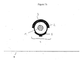
これらおよび他の目的および先行技術の欠点は、以下の近接照射療法のための放射性放射線源によって解決および克服することができる。近接照射療法のための該放射性放射線源は、細長い閉じこめ手段(2)内に細長い放射線発射エレメント(1)を有し、放射線発射エレメントの縦軸と閉じ込め手段の縦軸とは整列にあり、前記閉じ込め手段は遮蔽セクション(3)と放射線遷移セクション(4)を含み、
−前記遮蔽セクション(3)は前記遮蔽セクションの方向に発射される放射線を実質上減衰するように前記放射線発射エレメントを少なくとも部分的にカバーし、
−前記放射線遷移セクション(4)は閉じ込め手段の縦軸に実質上沿って延び、そして遮蔽材料(5)を含み、
−前記遮蔽材料(5)は前記放射線発射エレメントから発射された放射線を、放射線源からあらかじめ選定した距離にある平面において、細長い閉じ込め手段の縦軸より実質的に大きい長さと、そして好ましくは閉じ込め手段の直径より実質上大きい直径を有する標的区域(6)の上に実質上均一な放射線線量が受取られるように減衰するのに適合している。
These and other objectives and deficiencies of the prior art can be solved and overcome by the following radioactive radiation source for brachytherapy. The radioactive radiation source for brachytherapy has an elongated radiation emitting element (1) in an elongated confinement means (2), the longitudinal axis of the radiation emitting element and the longitudinal axis of the confinement means being in alignment, The containment means comprises a shielding section (3) and a radiation transition section (4);
The shielding section (3) at least partially covers the radiation emitting element so as to substantially attenuate radiation emitted in the direction of the shielding section;
The radiation transition section (4) extends substantially along the longitudinal axis of the containment means and comprises a shielding material (5);
The shielding material (5) has a length substantially greater than the longitudinal axis of the elongated confinement means in a plane at a preselected distance from the radiation source, and preferably confinement means, from the radiation emitting element; Is adapted to attenuate so that a substantially uniform radiation dose is received over a target area (6) having a diameter substantially larger than
遮蔽材料(5)はその厚み、密度および/または組成を変えることによって放射線の減衰に適合させることができる。一般に前記遮蔽材料はその遮蔽性を変えることによって適合させることができる。 The shielding material (5) can be adapted for radiation attenuation by changing its thickness, density and / or composition. In general, the shielding material can be adapted by changing its shielding properties.
他の好ましい具体例は従属請求項に記載されている。 Other preferred embodiments are described in the dependent claims.
本発明の放射性放射線源は、近接照射療法および特に黄斑変性症、好ましくは年令関連黄斑変性症(AMD)の処置のような眼近接照射療法に適している。本発明の放射性放射線源は、好ましくは放射線発射エレメントの縦軸と閉じ込め手段の縦軸とが整列にあるように、細長い閉じ込め手段(2)内の細長い放射線発射エレメント(1)を有する近接照射のための放射線源を備えている。前記閉じ込め手段は遮蔽セクション(3)と放射線遷移セクション(4)を備えている。前記遮蔽セクション(3)は、前記遮蔽セクションの方向に発射されたどのような放射線をも実質的に減衰するように前記放射線発射エレメントを少なくとも部分的にカバーしている。好ましくは遮蔽セクションは該エレメントの約30〜90%、好ましくは40〜70%、もっと好ましくは50〜60%をカバーする。 The radioactive radiation source of the present invention is suitable for brachytherapy and in particular ocular brachytherapy such as the treatment of macular degeneration, preferably age-related macular degeneration (AMD). The radioactive radiation source of the present invention preferably comprises a near-irradiation with an elongated radiation emitting element (1) in an elongated confinement means (2) such that the longitudinal axis of the radiation emitting element and the longitudinal axis of the confinement means are in alignment. A radiation source for. Said containment means comprises a shielding section (3) and a radiation transition section (4). The shielding section (3) at least partially covers the radiation emitting element so as to substantially attenuate any radiation emitted in the direction of the shielding section. Preferably the shielding section covers about 30-90% of the element, preferably 40-70%, more preferably 50-60%.
前記放射線遷移セクション(4)は、閉じ込め手段の縦軸に実質的に沿って延び、そして遮蔽材料(5)を含んでいる。該遮蔽材料(5)は、放射線源からあらかじめ選定された距離にある平面において、細長い閉じ込め手段の縦軸より実質的に大きい長さと、そして好ましくは閉じ込め手段の直径より実質的に大きい直径を有する標的区域(6)の上に、実質上均一な放射線線量(30%より少ない、好ましくは20%より少ない、もっと好ましくは10%より少ない偏差)を受けるように、前記放射線発射エレメントから発射された放射線を減衰するのに適合している。この文脈において使用される術語「実質上」とは、意図した寸法において一般に少なくとも50%の拡大、好ましくは100%ないし200%の拡大を意味する。 Said radiation transition section (4) extends substantially along the longitudinal axis of the containment means and comprises a shielding material (5). The shielding material (5) has a length substantially larger than the longitudinal axis of the elongated confinement means and preferably a diameter substantially larger than the diameter of the confinement means in a plane at a preselected distance from the radiation source. Fired from the radiation emitting element to receive a substantially uniform radiation dose (less than 30%, preferably less than 20%, more preferably less than 10% deviation) on the target area (6) Suitable for attenuating radiation. The term “substantially” as used in this context means generally at least 50% enlargement, preferably 100% to 200% enlargement in the intended dimensions.
ここで使用される術語「細長い」とは、他の二つの軸よりも実質上大きい一つの軸を有する放射線発射エレメントのどのような形状をも意味する。好ましくは細長い放射線発射エレメントのアスペクト比(直径に対する縦軸の比)は≧2:1であり、もっと好ましくは5:1ないし25:1であり、もっと好ましくは8:1ないし17:1、特に10:1である。一般に放射線発射エレメントは、その断面がカテーテルまたは他の送達デバイス内のその運動を防止しない限り、どのような断面をも持つことができる。好ましくは、断面は円形、楕円形、または多面形であり、円形断面が好ましい。非円形断面の場合、上のアスペクト比は縦軸に直角な平面において最大の直径を用いて決定される。 As used herein, the term “elongate” means any shape of a radiation emitting element having one axis that is substantially larger than the other two axes. Preferably the aspect ratio of the elongated radiation emitting element (ratio of the longitudinal axis to the diameter) is ≧ 2: 1, more preferably 5: 1 to 25: 1, more preferably 8: 1 to 17: 1, in particular 10: 1. In general, the radiation emitting element can have any cross section as long as the cross section does not prevent its movement within a catheter or other delivery device. Preferably, the cross section is circular, elliptical or polyhedral, with a circular cross section being preferred. For non-circular cross sections, the above aspect ratio is determined using the largest diameter in a plane perpendicular to the vertical axis.
放射線発射エレメントは、その形が細長でそしてその意図する目的を妨害しない限り一般にどのような適当な形をも採用し得る。典型的にはそれは単一の中実もしくは中空体であろうが、しかし該エレメントの細長い形状を形成するように閉じ込め手段内に直列に配列されたいくつかの個々のエレメントからなることができる。好ましくはこのエレメントは単一体であり、それ自体が中空もしくは中実であり得る。もっと好ましくは放射線発射エレメントは、任意にコイルもしくはチューブの形に巻かれた円筒形ワイヤである。代ってもしいくつかのエレメントから構成されるならば、それらは直列に配置された球もしくは楕円球でも良い。 The radiation emitting element may generally take any suitable shape as long as its shape is elongated and does not interfere with its intended purpose. Typically it will be a single solid or hollow body, but can consist of several individual elements arranged in series within the containment means to form an elongated shape of the element. Preferably, this element is a single body and can itself be hollow or solid. More preferably, the radiation emitting element is a cylindrical wire, optionally wound in the form of a coil or tube. Alternatively, if it is composed of several elements, they may be spheres or ellipsoids arranged in series.
細長い放射線発射エレメントは閉じ込め手段内にシール封入される。この閉じ込め手段(2)は細長い形を有し、その縦軸は典型的には放射線発射エレメントの縦軸と整列にあり、そして好ましくは平行に配置される。ここでいう「平行に配置」とは互いに向ってそれぞれの縦軸の僅かな傾き、例えば20°まで、好ましくは10°までの傾きを排除しない。これは長さが実質上同一方向である距離である。好ましくは閉じ込め手段はその寸法が放射線発射エレメントの外径寸法と一致し、そのため後者は閉じ込め手段内にぴったりフィットする。 The elongated radiation emitting element is sealed within the containment means. This containment means (2) has an elongated shape, the longitudinal axis of which is typically aligned with the longitudinal axis of the radiation emitting element and is preferably arranged parallel. Here, “arranged in parallel” does not exclude slight inclinations of the respective vertical axes toward each other, for example, up to 20 °, preferably up to 10 °. This is a distance whose length is substantially in the same direction. Preferably the confinement means has its dimensions matching the outer diameter dimension of the radiation emitting element, so that the latter fits snugly within the confinement means.
閉じ込め手段またはカバースリーブの外側寸法は、適用可能な場合、典型的には放射線発射エレメントの寸法を規定するであろう。放射線発射エレメント自体は一般に当業者が選ばれた処置部位に適していると考えるどのような長さをも持つことができる。典型的にはそれは≦1〜25mm、好ましくは1〜15mm、もっと好ましくは2〜10mm、最も好ましくは2〜5mmの長さを持つであろう。同様に、放射線源は典型的には0.1〜2.0mm、好ましくは0.6〜1.2mm、最も好ましくは0.8〜1.2mmの直径を持つであろう。 The outer dimensions of the containment means or cover sleeve will typically define the dimensions of the radiation emitting element, if applicable. The radiation emitting element itself can generally have any length that one skilled in the art deems appropriate for the selected treatment site. Typically it will have a length of ≦ 1-25 mm, preferably 1-15 mm, more preferably 2-10 mm, most preferably 2-5 mm. Similarly, the radiation source will typically have a diameter of 0.1 to 2.0 mm, preferably 0.6 to 1.2 mm, and most preferably 0.8 to 1.2 mm.
放射線発射エレメント(1)は、典型的には0.1〜1mm、好ましくは0.2〜0.8mmの範囲の適合し得る外径を持つ。もっと好ましくは、放射線発射エレメントは0.1〜0.5mm、最も好ましくは0.3〜0.4mmの範囲内の外径を有する。閉じ込め手段(2)の内径はその中にエレメント(1)を収容するように適切に選ばれる。本発明の放射線源の上で述べた寸法は典型的にはその閉じ込め手段に関する。しかしながら本発明の放射線源は放射線源を所望の処置部位へ進めるのに適切な長さを持ったカテーテルまたはアプリケーターへ取り付けてもよい。同様に、放射線源は慣用のアフターローディング技術を使用してアプリケーターまたはカテーテルを用いて所定位置に配置することができる。好ましい具体例においては、閉じ込め手段は、公開されたアメリカ特許出願No.2002/0115902に開示されているように、その先端においてカテーテル/アプリケーターの一体部分を形成し、そして放射線発射エレメントはその中に固着される。 The radiation emitting element (1) typically has a compatible outer diameter in the range of 0.1 to 1 mm, preferably 0.2 to 0.8 mm. More preferably, the radiation emitting element has an outer diameter in the range of 0.1 to 0.5 mm, most preferably 0.3 to 0.4 mm. The inner diameter of the confinement means (2) is appropriately chosen to accommodate the element (1) therein. The dimensions mentioned above for the radiation source of the invention typically relate to the containment means. However, the radiation source of the present invention may be attached to a catheter or applicator having an appropriate length to advance the radiation source to the desired treatment site. Similarly, the radiation source can be placed in place using an applicator or catheter using conventional afterloading techniques. In a preferred embodiment, the containment means is a published US patent application no. As disclosed in 2002/0115902, it forms an integral part of the catheter / applicator at its tip and the radiation emitting element is secured therein.
代替具体例においては、遮蔽セクションおよび遷移セクションは、場合によりカバースリーブと共に、アプリケーター先端へそれと一体に形成されることができる。カプセル内にシール封入された放射線発射エレメントを含んでいる慣用のシードをアプリケーターの先端へアフターローディングによってその後動かし、本発明の最終放射線源を形成しても良い。 In an alternative embodiment, the shielding and transition sections can be integrally formed with the applicator tip, optionally with a cover sleeve. A conventional seed containing a radiation emitting element sealed within a capsule may then be moved by afterloading to the tip of the applicator to form the final radiation source of the present invention.
閉じ込め手段は、細長い放射線発射エレメントに加えて、使用時放射線源の前進をモニターすることを許容する放射線不透過性マーカーを含んでいる。そのような放射線不透過性マーカーは中空コイル形または中空円筒形放射線発射エレメントの中心コア内に設けることができ、および/または放射線発射エレメントの片側もしくは両側に別体として設けるか、または例えば前記放射線発射エレメントを形成するいくつかの球の間に散圧させてもよい。放射線発射エレメントを含む閉じ込め手段内に放射線不透過性マーカーを含める他の具体例も当業者には良く知られている。これらも本発明によって包含される。 In addition to the elongated radiation emitting element, the containment means includes a radiopaque marker that permits monitoring of the advancement of the radiation source in use. Such radiopaque markers can be provided in the central core of the hollow coil or hollow cylindrical radiation emitting element and / or provided separately on one or both sides of the radiation emitting element, or for example said radiation A pressure may be applied between several spheres forming the firing element. Other embodiments of including a radiopaque marker within a containment means including a radiation emitting element are well known to those skilled in the art. These are also encompassed by the present invention.
閉じ込め手段は、遮蔽セクション(3)と、放射線遷移セクション(4)とからなる。これら二つのセクションは合体して閉じ込め手段またはそのセクションを形成することができ、あるいは第1の層またはカプセル(2a)の内側または外側に別体のセクションとして設けることができ、該層またはカプセルが閉じ込め機能を提供するように放射線発射エレメントをシールして封入する。一例として、第1のカプセル(2a)は端部プラグを有する中空円筒の形に形成することができ、該カプセルが放射線発射エレメントをシールして封入する。 The containment means consists of a shielding section (3) and a radiation transition section (4). These two sections can be combined to form a containment means or section thereof, or can be provided as a separate section inside or outside the first layer or capsule (2a), the layer or capsule being The radiation emitting element is sealed and encapsulated to provide a containment function. As an example, the first capsule (2a) can be formed in the form of a hollow cylinder with end plugs, which seal and enclose the radiation emitting element.
カプセル(2a)のまわりに、しかし好ましくはカプセル(2a)内に、遮蔽セクション(3)および放射線遷移セクションよりなるおよび/または形成する第2のシリンダーを設けることができ、放射線遷移セクションは例えば第2のシリンダーをその片側において壁厚を変えることによって提供される。第1のカプセル内にこれらのセクションを設けることは、挿入および取出しの間傷を発生し得る放射線源外側の鋭利な縁を防止できるという利益を有する。代ってカバースリーブを以下に論ずるように設けることができる。 Around the capsule (2a), but preferably in the capsule (2a), a second cylinder can be provided, consisting of and / or forming a shielding section (3) and a radiation transition section, Two cylinders are provided by varying the wall thickness on one side. Providing these sections within the first capsule has the benefit of preventing sharp edges outside the radiation source that can cause scratches during insertion and removal. Alternatively, a cover sleeve can be provided as discussed below.
他の具体例においては、遮蔽セクション(3)および放射線遷移セクション(4)は閉じ込め手段の一体部品である。再び放射線遷移セクション(4)は例えばあらかじめ決められたセクションにおいて閉じ込め手段の壁厚を変えること、特に減らすことによって設けることができる。 In other embodiments, the shielding section (3) and the radiation transition section (4) are an integral part of the containment means. Again, the radiation transition section (4) can be provided, for example, by changing the wall thickness of the confinement means, in particular in a predetermined section.
遮蔽セクション(3)は放射線発射エレメントを少なくとも部分的にカバーし、遮蔽セクションの方向に発射される放射線を実質的に減衰する。ここで使用される術語「実質的に減衰」とは、遮蔽方向への放射線を、処置すべき部位の周囲の組織の損傷を防止し、そして医療従事者の望まない曝露を防止するように望ましい低いレベルへ減衰させることを意味する。特に、減衰は好ましくは前記方向へ発射される放射線を90%以上、好ましくは99%以上、最も好ましくは100%減らすように達成される。 The shielding section (3) at least partially covers the radiation emitting element and substantially attenuates the radiation emitted in the direction of the shielding section. As used herein, the term “substantially attenuated” is desirable so that radiation in the shielding direction prevents damage to the tissue surrounding the area to be treated and prevents unwanted exposure of medical personnel. It means attenuating to a lower level. In particular, attenuation is preferably achieved to reduce radiation emitted in that direction by 90% or more, preferably 99% or more, and most preferably 100%.
放射線遷移セクション(4)は閉じ込め手段(2)の第2の部分を形成する。このセクションは閉じ込め手段との縦軸に実質的に沿って延びる。ここで使用される術語「実質的に沿って」とは、放射線遷移セクションが閉じ込め手段の縦軸の上に整列し、好ましくは閉じ込め手段の縦軸の上に中心が整列し、そしてその長さが閉じ込め手段内に含まれる放射線発射エレメントの縦軸の長さの長い部分に少なくとも相当し、そして好ましくは閉じ込め手段自体の縦軸の長さに少なくとも相当することを意味する。典型的には、放射線遷移セクションはそれ自身閉じ込め手段の縦軸の50%以上、もっと好ましくは60〜100%、最も好ましくは75〜95%の上をそれに沿って延びるであろう。 The radiation transition section (4) forms the second part of the confinement means (2). This section extends substantially along the longitudinal axis with the containment means. The term “substantially along” as used herein means that the radiation transition section is aligned on the longitudinal axis of the containment means, preferably centered on the longitudinal axis of the containment means, and its length. Means at least the long part of the length of the longitudinal axis of the radiation emitting element contained within the containment means, and preferably at least the length of the longitudinal axis of the containment means itself. Typically, the radiation transition section will itself extend along more than 50% of the longitudinal axis of the containment means, more preferably 60-100%, most preferably 75-95%.
放射線遷移セクション(4)は、照射すべき標的区域に対向したまたは対向させようとする本発明の放射線源(その閉じ込め手段)の横または面に配置される。 The radiation transition section (4) is arranged beside or on the side of the radiation source of the invention (its containment means) opposite or intended to face the target area to be irradiated.
放射線遷移セクション(4)は遮蔽材料(5)を含む。この遮蔽材料(5)は、放射線源からあらかじめ選定した距離にある平面において、閉じ込め手段の直径より実質的に大きい直径と、細長い閉じ込め手段の縦軸より実質的に大きい長さを持っている標的区域(6)の上に実質上均一な放射線線量が受けられるような態様で、放射線発射エレメントから発射された放射線を減衰するように適合している。 The radiation transition section (4) includes a shielding material (5). The shielding material (5) has a target having a diameter substantially larger than the diameter of the confinement means and a length substantially larger than the longitudinal axis of the elongated confinement means in a plane at a preselected distance from the radiation source. It is adapted to attenuate the radiation emitted from the radiation emitting element in such a way that a substantially uniform radiation dose is received on the area (6).
遮蔽材料(5)の適合化はその遮蔽性の適合化によって起こる。これはその厚み、密度および/または組成を変えることによって達成し得る。好ましい具体例においては、遮蔽材料(5)はその厚みを変えることによって適合化される。この具体例においては適合化は特に標的区域(6)へより近い区域の放射線遷移セクション(4)部分において標的区域から遠い部分よりも大きい厚みを遮蔽材料が提供することによって達成することができる。 Adaptation of the shielding material (5) occurs by adapting its shielding properties. This can be achieved by changing its thickness, density and / or composition. In a preferred embodiment, the shielding material (5) is adapted by changing its thickness. In this embodiment, adaptation can be achieved in particular by the shielding material providing a greater thickness in the radiation transition section (4) part of the area closer to the target area (6) than in the part far from the target area.
近接照射療法に適する発射された放射線は空気、体液または組織中にそのままにして置くだけで効果的に遮蔽されることを考慮すれば、(i)閉じ込め手段、(ii)流体または空気、および(iii)組織を通る放射線ビームのどんな走行距離もあらかじめ選定した標的区域において受取られる放射線線量を効果的に減らすであろう。標的区域の平面に対して直角な方向に発射される放射線(すなわち標的区域に最も近い放射線源の部分)は最短距離を走行し、それ故最小の減衰を経験するであろう。直角方向に対して傾いた方向に発射された放射線はもっと長く走行し、それ故もっと高程度の減衰を経験するであろう。減衰の程度は走行距離、従って傾き角度と、さらに放射線が通過する媒体に依存する。 Considering that the emitted radiation suitable for brachytherapy is effectively shielded by simply leaving it in air, body fluid or tissue, (i) containment means, (ii) fluid or air, and ( iii) Any mileage of the radiation beam through the tissue will effectively reduce the radiation dose received in the preselected target area. Radiation emitted in a direction perpendicular to the plane of the target area (ie, the portion of the radiation source closest to the target area) will travel the shortest distance and therefore experience minimal attenuation. Radiation emitted in a direction tilted with respect to the right angle will run longer and therefore will experience a higher degree of attenuation. The degree of attenuation depends on the distance traveled, and thus the tilt angle, and also the medium through which the radiation passes.
放射線源自体の寸法より大きい標的区域において均一な放射線線量を達成することを許容するためには、傾いた方向に発射された放射線も使用する必要がある。しかしながらこれらは標的区域においてより少ない放射線線量を送達し易い。本発明は、発射された放射および特に直角方向に発射された放射線をこの差に対抗し、最終的にあらかじめ選定された標的区域において均一な放射線線量が得られるように変調(適切な減衰によって)する遮蔽材料を提供する。これによって非常に小さい放射線源がより大きい標的区域を効果的にかつ均一に照射するために使用できる。 In order to allow a uniform radiation dose to be achieved in a target area that is larger than the size of the radiation source itself, radiation emitted in a tilted direction must also be used. However, they are more likely to deliver a lower radiation dose in the target area. The present invention counters this difference in emitted radiation and especially in orthogonal radiation, and ultimately modulates (with appropriate attenuation) to obtain a uniform radiation dose in a preselected target area. A shielding material is provided. This allows a very small radiation source to be used to effectively and uniformly illuminate a larger target area.
特に好ましい具体的においては、遮蔽セクション(3)は放射線発射エレメント(1)をその少なくとも片側においてその縦軸の全長の上をカバーすることができる。従って放射線源のこの側ヘの放射線の実質的の発射を防止することができる。その時放射線遷移セクション(4)は好ましくは遮蔽セクション(3)の反対側の放射線発射エレメントの側に配置される。 In a particularly preferred embodiment, the shielding section (3) can cover the radiation emitting element (1) on at least one side thereof over the entire length of its longitudinal axis. Thus, substantial emission of radiation to this side of the radiation source can be prevented. The radiation transition section (4) is then preferably arranged on the side of the radiation emitting element opposite the shielding section (3).
好ましい具体例においては、遮蔽材料(5)は、有利には標的区域に最も近い部分において放射線発射エレメントの縦軸の上にそれに沿ってより高い遮蔽能力(例えばより大きい厚みにおいて)を中心に提供することができる。この中心部分のほかに、より小さい遮蔽能力の(例えばより小さい厚みの)遮蔽材料が備えられる。これは中心部分の全長またはその部分長さを通じて可能である。好ましくはより小さい厚みの遮蔽材料が中心部の両側においてその全長の上に、または放射線発射エレメントの中心部分へ向ってより高い遮蔽能力(例えばより大きい厚み)の区域を残して、放射線発射エレメントの端部へ向って設けられる。 In a preferred embodiment, the shielding material (5) is advantageously provided on the longitudinal axis of the radiation emitting element along the longitudinal axis of the radiation emitting element in the part closest to the target area, centered at a higher shielding capacity (eg at a greater thickness). can do. In addition to this central portion, a shielding material with a smaller shielding capacity (eg a smaller thickness) is provided. This is possible through the entire length of the central part or its partial length. Preferably a smaller thickness of the shielding material is placed on either side of the central part over its entire length or towards the central part of the radiation emitting element, leaving an area of higher shielding capacity (eg greater thickness). It is provided toward the end.
最も好ましい具体例においては、遮蔽材料(5)は、標的区域(6)から遠い放射線遷移セクション(4)の部分においてくぼみ、特にくぼんだ窓(遮蔽材料なし)を含むことができる。この場合遮蔽材料(5)は再び放射線発射エレメントの縦軸の上にそれに沿って中心に設けられ、その片側または両側に1または2以上のくぼみが設けられる。好ましくは2以上(2〜10、好ましくは4〜8)のくぼみの配置は遮蔽材料(5)中心軸に対して対称的である。 In the most preferred embodiment, the shielding material (5) may comprise a depression, particularly a recessed window (no shielding material), in the portion of the radiation transition section (4) remote from the target area (6). In this case, the shielding material (5) is again centered on and along the longitudinal axis of the radiation emitting element, with one or more indentations on one or both sides. Preferably, the arrangement of the recesses of 2 or more (2-10, preferably 4-8) is symmetrical with respect to the central axis of the shielding material (5).
遮蔽材料(5)は、その密度および/または組成を変えることによってその遮蔽効果を変えることにより適合化させることもできる。この場合、高い遮蔽効果を有する材料を標的区域(6)に近い放射線遷移セクション(4)の部分に使用することができ、他方標的区域(6)から遠い放射線遷移セクション(4)の部分にはより低い遮蔽効果を持つ材料を使用することができる。遮蔽材料の組成は、例えば鉄ボンバードメントもしくはスパッタリング等によって遮蔽材料全体を通じて変えることができる。 The shielding material (5) can also be adapted by changing its shielding effect by changing its density and / or composition. In this case, a material with a high shielding effect can be used for the part of the radiation transition section (4) close to the target area (6), while for the part of the radiation transition section (4) far from the target area (6) Materials with a lower shielding effect can be used. The composition of the shielding material can be varied throughout the shielding material, for example by iron bombardment or sputtering.
もっと詳しくは、金属遮蔽材料の場合、その組成は、組成中の所望の変化を得るように重い金属材料での鉄ボンバードメントによって変えることができる。例えば放射線遷移セクション(4)のもっと透過性のセクションを鉄ボンバードメントの間にマスクし、そしてすべての他の部分はそれらの減衰係数を所望程度へ増加させるようにより重い材料でボンバードメントすることができる。 More particularly, in the case of metal shielding materials, the composition can be varied by iron bombardment with heavy metal materials to obtain the desired change in composition. For example, the more transmissive section of the radiation transition section (4) may be masked between iron bombardments, and all other parts may be bombarded with heavier materials to increase their attenuation coefficient to the desired degree. it can.
好ましい具体例においては、放射線遷移セクション(4)の遮蔽材料(5)は、放射線遷移セクションと(4)を通って発射される放射線が実質的に均一な放射線線量を提供するように実質上平坦な円形の標的区域に入射するように適合化されている。 In a preferred embodiment, the shielding material (5) of the radiation transition section (4) is substantially flat so that the radiation emitted through the radiation transition section and (4) provides a substantially uniform radiation dose. Adapted to be incident on a circular target area.
図1に示した具体例においては、遮蔽セクション(3)および放射線遷移セクション(4)は閉じ込め手段(2)の一体部分を形成している。 In the embodiment shown in FIG. 1, the shielding section (3) and the radiation transition section (4) form an integral part of the containment means (2).
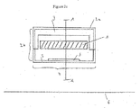
代って図2に示すように、閉じ込め手段(2)は、放射線発射エレメント(1)をシール封入する第1の層またはカプセル(2a)を含むことができ、さらに第1の層またはカプセル(2a)から別々にその外側(図示せず)または図2に示したように内側に設けられた遮蔽セクション(3)および放射線遷移セクション(4)を含んでいる。好ましくは遮蔽セクションおよび放射線遷移セクションは図2に示されているように層もしくはカプセル(2a)の内側に設けられる。この場合例えば、閉じ込め手段(2)は円筒形の第1のカプセル(2a)よりなり、このカプセルは放射線発射エレメント(1)をシール封入するためのエンドキャップを備えている。その時遮蔽セクション(3)および放射線遷移セクション(4)は第2のシリンダーの形に提供されることができる。放射線遷移セクション(4)は、第2のシリンダーの壁厚をその半円周において適切に適合化することにより、または上で記載したような適切な態様において鉄ボンバードメントによりその組成を変えることによって第2のシリンダー上に設けられる。第2のシリンダーは任意の適切な方法、例えば溶接または接着剤の使用によって第1のカプセルへ固着される。 Alternatively, as shown in FIG. 2, the containment means (2) can include a first layer or capsule (2a) that seals the radiation emitting element (1), and further includes a first layer or capsule ( 2a) includes a shielding section (3) and a radiation transition section (4) provided separately from the outside (not shown) or inside as shown in FIG. Preferably the shielding section and the radiation transition section are provided inside the layer or capsule (2a) as shown in FIG. In this case, for example, the confinement means (2) comprises a cylindrical first capsule (2a), which has an end cap for sealingly enclosing the radiation emitting element (1). The shielding section (3) and the radiation transition section (4) can then be provided in the form of a second cylinder. The radiation transition section (4) is obtained by appropriately adapting the wall thickness of the second cylinder in its semicircumference, or by changing its composition by iron bombardment in a suitable manner as described above. Provided on the second cylinder. The second cylinder is secured to the first capsule by any suitable method, such as welding or using an adhesive.
本発明の発射エレメントは医療目的に対して適していることが知られた適切な放射活性放射性発射核種を含むことができる。好ましい具体例においては、放射性発射エレメントはβ−線発射エレメントである。好ましい核種は少なくとも500keVのβ−線の最大粒子エネルギーを有し、好ましくはもし可能であればγ−線のための光子エネルギーを持たないものから選ばれる。代って20keVないし200keV、もっと好ましくは20keVないし100keVの光子エネルギーを有するX線もしくはソフトγ−線核種を使用することができる。これら放射性物質は、それらの短い減衰距離のため生物学的材料および組織に最も望ましく使用されるソフトエミッターである。これらエネルギーのβ源電子は典型的にはヒト組織中へたった1ないし10mm貫通するだけである。それらはプラスチック材料でも容易に遮蔽される。従って処理すべき部位を囲む隣接組織への損傷を最小化することができる。 The launch elements of the present invention can include any suitable radioactive radioactive launch nuclide known to be suitable for medical purposes. In a preferred embodiment, the radioactive launch element is a β-ray launch element. Preferred nuclides are selected from those having a maximum particle energy of β-rays of at least 500 keV, preferably having no photon energy for γ-rays if possible. Alternatively, X-rays or soft γ-ray nuclides having a photon energy of 20 keV to 200 keV, more preferably 20 keV to 100 keV can be used. These radioactive materials are the most desirable soft emitters used in biological materials and tissues due to their short attenuation distance. These energy β-source electrons typically only penetrate 1 to 10 mm into human tissue. They are also easily shielded with plastic materials. Thus, damage to adjacent tissue surrounding the site to be treated can be minimized.
好ましい具体例においては、放射線発射エレメントはY−90,Sr−90/Y−90,Tm−170,P−32,Cl−36,Ce−144,Pr−144,Tb−160,Ta−182,Tl−204,Sn−123,Re−188,Ir−192およびSe−75よりなる群から選ばれた核種を含む。最も好ましくは、放射線発射エレメントは核種Y−90,Tl−204,P−32またはTm−170の一つを含む。核種は非放射性支持体上に支持されることができ、または金属、プラスチックまたはセラミックマトリックスに含めることができる。これら材料の混合物も使用し得る。好ましい具体例は核種がマトリックス中に埋め込まれ、最も好ましい金属マトリックスが使用される。これらにおいて核種は元素形すなわち合金を形成するように埋め込まれるか、または酸化物、ハロゲン化物、炭化物もしくは窒化物等のような化合物の形で埋め込まれる。対応する適当な放射線発射エレメントは、例えば参照としてここに取入れるヨーロッパ特許出願EP1084733Aに開示されている。 In a preferred embodiment, the radiation emitting elements are Y-90, Sr-90 / Y-90, Tm-170, P-32, Cl-36, Ce-144, Pr-144, Tb-160, Ta-182. A nuclide selected from the group consisting of Tl-204, Sn-123, Re-188, Ir-192 and Se-75. Most preferably, the radiation emitting element comprises one of nuclides Y-90, Tl-204, P-32 or Tm-170. The nuclide can be supported on a non-radioactive support or can be included in a metal, plastic or ceramic matrix. Mixtures of these materials can also be used. In a preferred embodiment, the nuclide is embedded in the matrix and the most preferred metal matrix is used. In these, the nuclides are embedded so as to form elemental forms, ie alloys, or in the form of compounds such as oxides, halides, carbides or nitrides. A corresponding suitable radiation emitting element is disclosed, for example, in European Patent Application EP 1084733 A, which is hereby incorporated by reference.
遮蔽セクション(3)は金属、セラミックまたはプラスチック材料、好ましくは金属材料、最も好ましくは高原子番号金属から選ばれた金属材料を含み、そして好ましくはそれらからなる。好ましくはこれらの金属はPt,Pd,Au,Ag,Ir,Pb,Wおよびそれらの合金、化合物、およびそれらのコンポジットおよび混合物よりなる群から選ばれる。特にこれらの炭化物、窒化物および複合材料を使用することができる。 The shielding section (3) comprises and preferably consists of a metallic, ceramic or plastic material, preferably a metallic material, most preferably a high atomic number metal. Preferably these metals are selected from the group consisting of Pt, Pd, Au, Ag, Ir, Pb, W and their alloys, compounds, and composites and mixtures thereof. In particular, these carbides, nitrides and composite materials can be used.
閉じ込め手段(2,2a)は金属、セラミックまたはプラスチックを含み、そして好ましくはそれらからなる。金属材料の場合、これらは好ましくはAl,Ag,Au,Pb,Cd,Ce,Cr,Co,Cu,Fe(特にステンレス鋼)、Hg,Hf,Bi,In,Mg,Mn,Mo,Nb,Ni,Pd,Pt,Pr,Re,Rh,Sn,Si,Ta,Ti,Tb,Th,V,W,Y,Yb,Zn,Zrおよびそれらの合金、化合物、コンポジットおよび混合物よりなる群から選ばれる。これら材料の炭化物および窒化物を使用することができる。好ましいのはTiおよびその合金のような生体適合性材料である。遮蔽セクションが閉じ込め手段の一体部分を形成する場合、両者は好ましくは同じ材料から製作される。この場合上で挙げた高原子番号金属が典型的に使用される。 The containment means (2, 2a) comprises and preferably consists of metal, ceramic or plastic. In the case of metallic materials, these are preferably Al, Ag, Au, Pb, Cd, Ce, Cr, Co, Cu, Fe (especially stainless steel), Hg, Hf, Bi, In, Mg, Mn, Mo, Nb, Selected from the group consisting of Ni, Pd, Pt, Pr, Re, Rh, Sn, Si, Ta, Ti, Tb, Th, V, W, Y, Yb, Zn, Zr and their alloys, compounds, composites and mixtures It is. Carbides and nitrides of these materials can be used. Preference is given to biocompatible materials such as Ti and its alloys. If the shielding section forms an integral part of the containment means, both are preferably made from the same material. In this case, the high atomic number metals listed above are typically used.
閉じ込め手段は好ましくはチューブ状もしくはシリンダー形に提供される。放射線発射エレメントのシール封入のため、このチューブ状またはシリンダー状形状はその両端にエンドキャップもしくはエンドプラグを備えることができる。同様に本発明に従った放射線発射エレメント(1)は、好ましくは閉じ込め手段の内径に密にフィットするような直径を有するチューブまたはシリンダー形に提供し得る。しかしながら放射線発射エレメントは、一以上の球形エレメント(1a)からなることができ、これらは典型的には閉じ込め手段の内径にマッチする直径の球であるが、小さい球も同様に使用することができる。 The containment means is preferably provided in the form of a tube or cylinder. For sealing the radiation emitting element, this tubular or cylindrical shape can be equipped with end caps or end plugs at both ends. Similarly, the radiation emitting element (1) according to the invention can be provided in the form of a tube or cylinder, preferably having a diameter so as to closely fit the inner diameter of the containment means. However, the radiation emitting element can consist of one or more spherical elements (1a), which are typically spheres with a diameter that matches the inner diameter of the containment means, although small spheres can be used as well. .
本発明の放射線源は閉じ込め手段のまわりに設けられたカバースリーブをさらに備えることができる。該カバースリーブは必ずしも閉じ込め手段をシール封入する必要はないが、シール封入が好ましい。例として、カバースリーブは閉じ込め手段のまわりに設けられた(第3の)シリンダーの形で提供し得る。 The radiation source of the present invention may further comprise a cover sleeve provided around the containment means. The cover sleeve does not necessarily need to seal the containment means, but is preferably sealed. As an example, the cover sleeve may be provided in the form of a (third) cylinder provided around the containment means.
カバースリーブは適切な耐放射線性、非腐食性、生体適合性材料で製作される。好ましくはそれは上で挙げた閉じ込め手段のための金属材料からなり、Ti,Ni,Fe(ステンレス鋼)およびそれらの合金が特に好ましい。 The cover sleeve is made of a suitable radiation resistant, non-corrosive, biocompatible material. Preferably it consists of the metallic materials for the confinement means mentioned above, with Ti, Ni, Fe (stainless steel) and their alloys being particularly preferred.
閉じ込め手段のまわりにカバースリーブを設置することは、(1)必ずしも生体適合性でない高Z材料が体内へ浸出するのを防止することができ、(2)閉じ込め手段の縁が挿入および取出し時にまわりの組織を損傷するのを防止するようにカバーされ、そして(3)放射線源を再使用のため容易に清浄化および滅菌できるという利益を提供する。 Placing a cover sleeve around the containment means can (1) prevent high-Z material that is not necessarily biocompatible from leaching into the body, and (2) the edge of the containment means around the insertion and removal. And (3) provides the benefit that the radiation source can be easily cleaned and sterilized for reuse.
閉じ込め手段と同様に、カバースリーブもアプリケーター先端へ取付けるかまたはその一部を形成することができる。例えばその中空円筒形延長部として閉じ込め手段を収容し、エンドプラグによってその中シールされる。エンドプラグは好ましくはレーザー溶接によって取付けられる。 Similar to the containment means, the cover sleeve can be attached to or form part of the applicator tip. For example, it contains the containment means as its hollow cylindrical extension and is sealed therein by an end plug. The end plug is preferably attached by laser welding.
本発明の放射線源の閉じ込め手段に放射線遮蔽セクション(3)および放射線遷移セクション(4)を設けることにより、本発明の放射線源は、軸方向に均一な放射線パターン(すなわちその周縁のまわりの均一な放射線パターン)を示す先行技術放射線源と異なって、意図的に不均一な放射線パターンを許容する。もっと詳しくは、発射された放射線は放射線源の少なくとも一方の側において遮蔽される。従って処置すべき部位に対向しそしてそれを囲む健康な組織の不当な照射は、発射される放射線が適切に指向されるので防止することができる。このことは黄班変性症の場合の黄班の照射のような眼科応用において特に重要である。これらの場合には放射線源は黄班と網膜の間に配置することを要し、網膜の照射は高度に望ましくない。 By providing the radiation source confinement means of the present invention with a radiation shielding section (3) and a radiation transition section (4), the radiation source of the present invention has an axially uniform radiation pattern (ie, uniform around its periphery). Unlike prior art radiation sources that show radiation patterns), intentionally non-uniform radiation patterns are allowed. More particularly, the emitted radiation is shielded on at least one side of the radiation source. Thus, unjustified irradiation of healthy tissue facing and surrounding the site to be treated can be prevented because the emitted radiation is properly directed. This is particularly important in ophthalmic applications such as macular irradiation in the case of macular degeneration. In these cases, the radiation source needs to be placed between the macula and the retina, and irradiation of the retina is highly undesirable.
本発明の放射線源は、平行して網膜を照射することなく黄班の含まれるスポットの精密な照射を許容する。さらに放射線遷移セクション(4)の適切な適合化により、本発明の放射線源は処置すべき黄班部分の実質上均一な照射を許容する。加えて、この処置すべき部分は放射線源自体の直径および長さよりも実質上大きくすることができる。そのためより小さい放射線源をより大きい黄班のパッチを処置するために使用できる。これは勿論処置/手術の間に患者に発生するリスクを減らす。 The radiation source of the present invention allows precise irradiation of a spot containing macula without irradiating the retina in parallel. Furthermore, by appropriate adaptation of the radiation transition section (4), the radiation source of the present invention allows substantially uniform irradiation of the macular area to be treated. In addition, the portion to be treated can be substantially larger than the diameter and length of the radiation source itself. Therefore, a smaller radiation source can be used to treat larger macula patches. This of course reduces the risk that arises in the patient during the procedure / surgery.
本発明は限定を意図しない以下の実施例によって例証される。 The invention is illustrated by the following examples, which are not intended to be limiting.
実施例1
放射線源は、金属マトリックス、この場合はアルミニウムマトリックス中に分散されたイットリウム90の酸化物よりなるワイヤーを準備することによって製作された。ワイヤーは第1の金属シリンダーに挿入され、閉じ込め手段としてエンドプラグによってシールされた。第1の金属シリンダーはステンレス鋼製であり、エンドプラグも同じ材料製であった。シールされた第1の金属シリンダーはPt/Ir合金製の第2のシリンダーに挿入された。第2のシリンダーはシールされた第1のシリンダーをしっかり保持するための密接に一致する寸法で第1のシリンダーのまわりに設けられた。
Example 1
The radiation source was fabricated by providing a wire consisting of a metal matrix, in this case an oxide of yttrium 90 dispersed in an aluminum matrix. The wire was inserted into the first metal cylinder and sealed by an end plug as a containment means. The first metal cylinder was made of stainless steel and the end plug was made of the same material. The sealed first metal cylinder was inserted into a second cylinder made of Pt / Ir alloy. A second cylinder was provided around the first cylinder with closely matching dimensions to hold the sealed first cylinder firmly.
閉じ込め手段のまわりでそのシリンダー軸と整列した第2のシリンダーの第1の半周壁は遮蔽セクションを形成する。閉じ込め手段のまわりでそのシリンダー軸と整列した第2の半周壁は、第2のシリンダーの長さに沿ってPt/Ir合金の厚みを変えることによって放射線遷移セクションを形成する。 The first half wall of the second cylinder aligned with its cylinder axis around the confinement means forms a shielding section. The second half wall aligned with the cylinder axis around the containment means forms a radiation transition section by varying the thickness of the Pt / Ir alloy along the length of the second cylinder.
第2のシリンダーの縦軸に沿った中心クロスブリッジに沿って8個のくぼみ(7)が規則的パターンに設けられる。これらのくぼみは窓、すなわち下の第1のシリンダーへのアクセスを許容する開口を形成する。 Eight indentations (7) are provided in a regular pattern along the central cross bridge along the longitudinal axis of the second cylinder. These indentations form windows, ie openings that allow access to the first cylinder below.
この実施例の放射線源は、第2のシリンダーを収容しそれを保持するように第2のシリンダーのまわりに設けられた端部をプラグした薄壁の第3のシリンダーの形のカバースリーブをさらに含んでいる。カバースリーブはTiまたはTi合金製である。これは放射線源をシールし、そして第2のシリンダーの縁のカバーを提供する。すべてのシリンダーは互いに固着され、および/またはレーザー溶接によってシールされる。 The radiation source of this embodiment further comprises a cover sleeve in the form of a thin-walled third cylinder plugged at the end provided around the second cylinder to receive and hold the second cylinder. Contains. The cover sleeve is made of Ti or Ti alloy. This seals the radiation source and provides a cover for the edge of the second cylinder. All cylinders are secured to each other and / or sealed by laser welding.
この放射源の発射放射線フィールドが放射線源表面から約1〜2mmの距離において約4〜6mm直径の標的区域においてテストされた。フィールドは中心から外縁までの30%線量変動の限界内で均一であった。これと比較して、本発明による遷移セクションを持たない放射線源は中心から外縁まで50%より大きい偏差を示した。 The emission radiation field of this radiation source was tested in a target area of about 4-6 mm diameter at a distance of about 1-2 mm from the radiation source surface. The field was uniform within the limits of 30% dose variation from the center to the outer edge. In comparison, a radiation source without a transition section according to the invention showed a deviation of more than 50% from the center to the outer edge.
実施例2
実施例1と同様に、同じ材料から製作された閉じ込め手段および第2のシリンダー内の放射線発射エレメントが製作された。しかしながらこの場合は第2のシリンダーは図3a〜cに示した形状および構造を有していた。
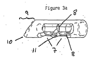
Example 2
As in Example 1, a containment means made from the same material and a radiation emitting element in the second cylinder were made. In this case, however, the second cylinder had the shape and structure shown in FIGS.
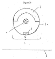
詳しくは、図3aは傾斜した先端部分(9)を有する中空円筒体の斜視図を示し、先端部分の最外縁(10)は面取りされている。4個のくぼみ(7)は拡大した断面(11)を有する中央バー(8)によって分離されている。放射線遮蔽セクション(3)は傾斜端の根本縁と整列してチューブの反対側に設けられる。放射線遷移セクション(4)は全体のチューブの傾斜端の先端/最外縁に整列してその側にある。 Specifically, FIG. 3a shows a perspective view of a hollow cylinder having an inclined tip portion (9), with the outermost edge (10) of the tip portion being chamfered. The four indentations (7) are separated by a central bar (8) having an enlarged cross section (11). A radiation shielding section (3) is provided on the opposite side of the tube in alignment with the root edge of the beveled end. The radiation transition section (4) is on that side aligned with the tip / outermost edge of the beveled end of the entire tube.
図3bは図3aの底面図である。この場合、縦方向バー(8a)はシリンダー全体の縦軸と整列し、そして面取り縁(10)の中央部分とも整列にあることが明瞭である。くぼみ(7)は第1のカプセル(2a)の円筒壁部分を切欠くことによって形成した窓として設けられ、チューブ状/シリンダー状閉じ込め手段内にシールされた放射線発射エレメントを収容すべきチューブ状内部体積へのアクセスを許容する。窓(7)は、好ましくは特にバー(8)によって囲まれそしてそれによって形成される部分において丸くされたコーナーが備えられる。 FIG. 3b is a bottom view of FIG. 3a. In this case, it is clear that the longitudinal bar (8a) is aligned with the longitudinal axis of the entire cylinder and is also aligned with the central part of the chamfered edge (10). The indentation (7) is provided as a window formed by cutting out the cylindrical wall portion of the first capsule (2a) and is a tube-like interior to receive a radiation emitting element sealed in a tube / cylindrical confinement means. Allow access to the volume. The window (7) is preferably provided with a rounded corner, particularly in the part enclosed by and formed by the bar (8).
図3cは図3bの線A−Aに沿った断面図である。図3cはシリンダー材料製の傾斜先端(9)および面取り縁(10)を示している。底側にある窓(7)はシリンダーの内側からクロスバー(8b)によって分離されていることが示されている。窓(7)は同様に丸味を帯びたコーナーを備え、そしてここではシリンダー(2a)の下側半周壁にわたって延びている。シリンダーの根本端はカテーテルへ取り付けのため開いている。端部分(12)はコンスタントな外径であるがテーパーしている。 3c is a cross-sectional view along line AA in FIG. 3b. Figure 3c shows an inclined tip (9) and chamfered edge (10) made of cylinder material. The bottom window (7) is shown separated from the inside of the cylinder by a crossbar (8b). The window (7) likewise has rounded corners and here extends over the lower half wall of the cylinder (2a). The base end of the cylinder is open for attachment to the catheter. The end portion (12) has a constant outer diameter but is tapered.
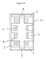
図4および5は遮蔽セクション(3)および遷移セクション(4)それぞれの上でこの放射線源で得られた線量率を示している。 4 and 5 show the dose rates obtained with this radiation source on the shielding section (3) and the transition section (4), respectively.
図4は、処置部位に相当する、放射線源の中心のまわりの約1mmのための11Gy/minの高レベル放射線プラトーを示している。図5は、放射線源の両側へ向ってもっと小さい線量(〜1.2Gy/min)の二つのピークを示し、それらは両方とも全部の遮蔽が起こる中心へ向って、そして両側へ向って急激に低下する。 FIG. 4 shows a high level radiation plateau of 11 Gy / min for about 1 mm around the center of the radiation source, corresponding to the treatment site. FIG. 5 shows two peaks of smaller doses (˜1.2 Gy / min) towards both sides of the radiation source, both of which towards the center where all shielding occurs and suddenly towards both sides. descend.
上に述べたように好ましい具体例に関して記載したが、この説明は当業者が特許請求の範囲に規定した本発明のいくつかの変形の可能性をその範囲を逸脱することなく認識するのを制限するものと考えるべきではない。 Although described with respect to the preferred embodiments as set forth above, this description limits the person skilled in the art from recognizing several variations of the invention as defined in the claims without departing from the scope thereof. Should not be considered to be.
Claims (24)
前記閉じ込め手段は遮蔽セクション(3)と放射線遷移セクション(4)とを含み;
前記遮蔽セクション(3)は前記放射線発射エレメントを前記遮蔽セクションの方向に発射された放射性を実質的に減衰するように少なくとも部分的にカバーし;
前記放射線遷移セクション(4)は前記閉じ込め手段の縦軸に実質的に沿って延び、かつ遮蔽材料(5)を含み;
前記遮蔽材料(5)は、放射線源からあらかじめ選定された距離にある平面において、細長い閉じ込め手段の縦軸より実質上大きい長さを有し、そして好ましくは該閉じ込め手段の直径より大きい直径を有する標的区域(6)の上に実質上均一な放射線線量が受取られるように、前記放射線発射エレメントから発射された放射線を減衰するように適合化されている;
ことを特徴とする放射線源。 A radioactive radiation source for brachytherapy in which an elongated radiation emitting element (1) is housed in an elongated confinement means (2) with the longitudinal axis of the elongated radiation emitting element and the longitudinal axis of the elongated confinement means aligned. There;
Said containment means comprises a shielding section (3) and a radiation transition section (4);
The shielding section (3) at least partially covers the radiation emitting element so as to substantially attenuate radiation emitted in the direction of the shielding section;
The radiation transition section (4) extends substantially along the longitudinal axis of the confinement means and includes a shielding material (5);
Said shielding material (5) has a length substantially greater than the longitudinal axis of the elongated confinement means in a plane at a preselected distance from the radiation source and preferably has a diameter larger than the diameter of said confinement means. Adapted to attenuate radiation emitted from the radiation emitting element so that a substantially uniform radiation dose is received on the target area (6);
A radiation source characterized by that.
細長い放射線発射エレメント(1)が細長い閉じ込め手段(2)内に、細長い放射線発射エレメントの縦軸と細長い閉じ込め手段の縦軸とが整列して収容されている近接照射療法のための放射性放射線源を提供するステップと、遮蔽セクション(3)および放射線遷移セクション(4)を提供するステップを含み;
前記遮蔽セクション(3)は前記放射線発射エレメントを前記遮蔽セクションの方向に発射された放射線を実質的に減衰するように少なくとも部分的にカバーし;
前記放射線遷移セクション(4)は閉じ込め手段の縦軸に実質的に沿って延び、かつ遮蔽材料(5)を含み、放射線源からあらかじめ選定した距離にある平面において、細長い閉じ込め手段の縦軸より実質上大きい長さを有し、そして好ましくは該閉じ込め手段の直径より大きい直径を有する標的区域(6)の上に実施上均一な放射線線量が受取られるように、前記放射線発射エレメントから発射された放射線を減衰するように減衰材料を適合化することによって放射線遷移セクション(4)を提供する、前記方法。 21. A method of fabricating a radiation source according to claim 1-20.
A radioactive radiation source for brachytherapy in which an elongated radiation emitting element (1) is housed in an elongated confinement means (2) with the longitudinal axis of the elongated radiation emitting element and the longitudinal axis of the elongated confinement means aligned. Providing and comprising providing a shielding section (3) and a radiation transition section (4);
The shielding section (3) at least partially covers the radiation emitting element so as to substantially attenuate radiation emitted in the direction of the shielding section;
Said radiation transition section (4) extends substantially along the longitudinal axis of the confinement means and comprises a shielding material (5), substantially in a plane at a preselected distance from the radiation source, from the longitudinal axis of the elongated confinement means. Radiation emitted from the radiation emitting element so that a substantially uniform radiation dose is received on a target area (6) having a large length above and preferably having a diameter larger than the diameter of the containment means. Providing the radiation transition section (4) by adapting the attenuating material to attenuate.
Applications Claiming Priority (2)
| Application Number | Priority Date | Filing Date | Title |
|---|---|---|---|
| EP03025416A EP1529554B1 (en) | 2003-11-05 | 2003-11-05 | Radioactive radiation source for ophthalmic brachytherapy |
| PCT/EP2004/012415 WO2005049139A1 (en) | 2003-11-05 | 2004-11-03 | Radioactive radiation source for ophthalmic brachytherapy |
Publications (1)
| Publication Number | Publication Date |
|---|---|
| JP2007509668A true JP2007509668A (en) | 2007-04-19 |
Family
ID=34429275
Family Applications (1)
| Application Number | Title | Priority Date | Filing Date |
|---|---|---|---|
| JP2006537240A Pending JP2007509668A (en) | 2003-11-05 | 2004-11-03 | Radioactive radiation sources for ophthalmic brachytherapy |
Country Status (9)
| Country | Link |
|---|---|
| EP (1) | EP1529554B1 (en) |
| JP (1) | JP2007509668A (en) |
| CN (1) | CN1878597A (en) |
| AT (1) | ATE334717T1 (en) |
| AU (1) | AU2004290507A1 (en) |
| BR (1) | BRPI0416279A (en) |
| CA (1) | CA2543544A1 (en) |
| DE (1) | DE60307288D1 (en) |
| WO (1) | WO2005049139A1 (en) |
Cited By (6)
| Publication number | Priority date | Publication date | Assignee | Title |
|---|---|---|---|---|
| JP2010506689A (en) * | 2006-10-16 | 2010-03-04 | オラヤ セラピューティクス,インコーポレーテッド | Eye radiosurgery |
| US8295437B2 (en) | 2006-12-13 | 2012-10-23 | Oraya Therapeutics, Inc. | Orthovoltage radiotherapy |
| US8363783B2 (en) | 2007-06-04 | 2013-01-29 | Oraya Therapeutics, Inc. | Method and device for ocular alignment and coupling of ocular structures |
| US8494116B2 (en) | 2007-12-23 | 2013-07-23 | Oraya Therapeutics, Inc. | Methods and devices for orthovoltage ocular radiotherapy and treatment planning |
| US8503609B2 (en) | 2007-12-23 | 2013-08-06 | Oraya Therapeutics, Inc. | Methods and devices for detecting, controlling, and predicting radiation delivery |
| US8506558B2 (en) | 2008-01-11 | 2013-08-13 | Oraya Therapeutics, Inc. | System and method for performing an ocular irradiation procedure |
Families Citing this family (14)
| Publication number | Priority date | Publication date | Assignee | Title |
|---|---|---|---|---|
| ATE488269T1 (en) | 2004-02-12 | 2010-12-15 | Neovista Inc | DEVICE FOR INTRAOCULAR BRACHYTHERAPY |
| WO2005115543A1 (en) | 2004-05-20 | 2005-12-08 | Wisconsin Alumni Research Foundation | Directionally emitting radioactive sources for brachytherapy |
| BRPI0618677A2 (en) | 2005-11-15 | 2011-09-06 | Neovista Inc | methods and apparatus for intraocular brachytherapy |
| EP2083919B1 (en) | 2006-10-02 | 2012-11-21 | Gad Shani | Thulium-based capsule and devices for use in high dose rate brachytherapy |
| DE102008030590A1 (en) | 2007-06-29 | 2009-01-08 | Carl Zeiss Surgical Gmbh | Radiotherapy device applicator for treating tumor in spinal column of patient, has base plate with base area, and guiding area connected to base plate, where diameter of guiding area is smaller or equal to diameter of base area |
| DE102009058581A1 (en) * | 2009-12-17 | 2011-06-22 | Carl Zeiss Surgical GmbH, 73447 | Applicator device for radiotherapy, fastening device and radiotherapy device |
| WO2014067546A1 (en) * | 2012-10-29 | 2014-05-08 | Technische Universität Dortmund | Device for use in episcleral plaque brachytherapy |
| EP3003482B1 (en) * | 2013-06-06 | 2020-08-05 | Universität Duisburg-Essen | Device for collimating electromagnetic radiation |
| US11318326B2 (en) | 2015-05-07 | 2022-05-03 | Qsa Global Inc. | Strontium sealed source |
| KR102541716B1 (en) | 2015-05-07 | 2023-06-08 | 일리노이즈 툴 워크스 인코포레이티드 | Strontium Sealed Source |
| WO2017205202A1 (en) * | 2016-05-24 | 2017-11-30 | Qsa Global Inc. | Low density spherical iridium source |
| CN106237547B (en) * | 2016-08-29 | 2019-03-08 | 西南医科大学附属医院 | A kind of production method of individuation short distance single tube applicating device |
| GB201714392D0 (en) | 2017-09-07 | 2017-10-25 | Marsteller Laurence | Methods and devices for treating glaucoma |
| WO2020069217A1 (en) * | 2018-09-28 | 2020-04-02 | Radiance Therapeutics, Inc. | Methods, systems, and compositions for maintaining functioning drainage blebs associated with minimally invasive micro sclerostomy |
Family Cites Families (2)
| Publication number | Priority date | Publication date | Assignee | Title |
|---|---|---|---|---|
| US6309339B1 (en) * | 1997-03-28 | 2001-10-30 | Endosonics Corporation | Intravascular radiation delivery device |
| US6482142B1 (en) * | 1997-07-24 | 2002-11-19 | Proxima Therapeutics, Inc. | Asymmetric radiation dosing apparatus and method |
-
2003
- 2003-11-05 EP EP03025416A patent/EP1529554B1/en not_active Expired - Lifetime
- 2003-11-05 DE DE60307288T patent/DE60307288D1/en not_active Expired - Lifetime
- 2003-11-05 AT AT03025416T patent/ATE334717T1/en not_active IP Right Cessation
-
2004
- 2004-11-03 AU AU2004290507A patent/AU2004290507A1/en not_active Abandoned
- 2004-11-03 CA CA002543544A patent/CA2543544A1/en not_active Abandoned
- 2004-11-03 CN CNA2004800328792A patent/CN1878597A/en active Pending
- 2004-11-03 WO PCT/EP2004/012415 patent/WO2005049139A1/en active Application Filing
- 2004-11-03 BR BRPI0416279-0A patent/BRPI0416279A/en not_active Application Discontinuation
- 2004-11-03 JP JP2006537240A patent/JP2007509668A/en active Pending
Cited By (23)
| Publication number | Priority date | Publication date | Assignee | Title |
|---|---|---|---|---|
| US8837675B2 (en) | 2006-10-16 | 2014-09-16 | Oraya Therapeutics, Inc. | Ocular radiosurgery |
| US8761336B2 (en) | 2006-10-16 | 2014-06-24 | Oraya Therapeutics, Inc. | Orthovoltage radiotherapy |
| US8611497B2 (en) | 2006-10-16 | 2013-12-17 | Oraya Therapeutics, Inc. | Portable orthovoltage radiotherapy |
| US8320524B2 (en) | 2006-10-16 | 2012-11-27 | Oraya Therapeutics, Inc. | Orthovoltage radiotherapy |
| US8995618B2 (en) | 2006-10-16 | 2015-03-31 | Oraya Therapeutics, Inc. | Portable orthovoltage radiotherapy |
| US8442185B2 (en) | 2006-10-16 | 2013-05-14 | Oraya Therapeutics, Inc. | Orthovoltage radiosurgery |
| US8855267B2 (en) | 2006-10-16 | 2014-10-07 | Oraya Therapeutics, Inc. | Orthovoltage radiosurgery |
| JP2010506689A (en) * | 2006-10-16 | 2010-03-04 | オラヤ セラピューティクス,インコーポレーテッド | Eye radiosurgery |
| US8295437B2 (en) | 2006-12-13 | 2012-10-23 | Oraya Therapeutics, Inc. | Orthovoltage radiotherapy |
| US8787524B2 (en) | 2006-12-13 | 2014-07-22 | Oraya Therapeutics, Inc. | Orthovoltage radiotherapy |
| US8306186B2 (en) | 2006-12-13 | 2012-11-06 | Oraya Therapeutics, Inc. | Orthovoltage radiotherapy |
| US9272161B2 (en) | 2006-12-13 | 2016-03-01 | Oraya Therapeutics, Inc. | Orthovoltage radiotherapy |
| US8457277B2 (en) | 2007-04-09 | 2013-06-04 | Oraya Therapeutics, Inc. | Orthovoltage radiosurgery |
| US8630388B2 (en) | 2007-06-04 | 2014-01-14 | Oraya Therapeutics, Inc. | Method and device for ocular alignment and coupling of ocular structures |
| US8923479B2 (en) | 2007-06-04 | 2014-12-30 | Oraya Therapeutics, Inc. | Method and device for ocular alignment and coupling of ocular structures |
| US8363783B2 (en) | 2007-06-04 | 2013-01-29 | Oraya Therapeutics, Inc. | Method and device for ocular alignment and coupling of ocular structures |
| US8503609B2 (en) | 2007-12-23 | 2013-08-06 | Oraya Therapeutics, Inc. | Methods and devices for detecting, controlling, and predicting radiation delivery |
| US8848869B2 (en) | 2007-12-23 | 2014-09-30 | Oraya Therapeutics, Inc. | Methods and devices for detecting, controlling, and predicting radiation delivery |
| US8494116B2 (en) | 2007-12-23 | 2013-07-23 | Oraya Therapeutics, Inc. | Methods and devices for orthovoltage ocular radiotherapy and treatment planning |
| US9025727B2 (en) | 2007-12-23 | 2015-05-05 | Oraya Therapeutics, Inc. | Methods and devices for orthovoltage ocular radiotherapy and treatment planning |
| US8506558B2 (en) | 2008-01-11 | 2013-08-13 | Oraya Therapeutics, Inc. | System and method for performing an ocular irradiation procedure |
| US8920406B2 (en) | 2008-01-11 | 2014-12-30 | Oraya Therapeutics, Inc. | Device and assembly for positioning and stabilizing an eye |
| US8512236B2 (en) | 2008-01-11 | 2013-08-20 | Oraya Therapeutics, Inc. | System and method for positioning and stabilizing an eye |
Also Published As
| Publication number | Publication date |
|---|---|
| CA2543544A1 (en) | 2005-06-02 |
| DE60307288D1 (en) | 2006-09-14 |
| WO2005049139A1 (en) | 2005-06-02 |
| ATE334717T1 (en) | 2006-08-15 |
| EP1529554A1 (en) | 2005-05-11 |
| EP1529554B1 (en) | 2006-08-02 |
| CN1878597A (en) | 2006-12-13 |
| BRPI0416279A (en) | 2007-01-23 |
| AU2004290507A1 (en) | 2005-06-02 |
Similar Documents
| Publication | Publication Date | Title |
|---|---|---|
| JP2007509668A (en) | Radioactive radiation sources for ophthalmic brachytherapy | |
| KR101634983B1 (en) | Methods and devices for minimally-invasive extraocular delivery of radiation to the posterior portion of the eye | |
| US7070554B2 (en) | Brachytherapy devices and methods of using them | |
| US6030333A (en) | Implantable radiotherapy device | |
| US6066083A (en) | Implantable brachytherapy device having at least partial deactivation capability | |
| CA2394562C (en) | Asymmetric radiation dosing apparatus and method | |
| US6796936B2 (en) | Implantable radiation therapy device having controllable radiation emission | |
| US20110207987A1 (en) | Methods And Devices For Delivering Appropriate Minimally-Invasive Extraocular Radiation | |
| JP2011139935A (en) | Brachytherapy method and applicator for treatment of metastatic lesion in load bearing region | |
| EP1997532B1 (en) | Ophthalmic applicator for treatment of pterygium or glaucoma using 32-P in combination with 103-Pd | |
| WO2000009197A1 (en) | Radioactive therapeutic seeds | |
| WO2015105539A9 (en) | Radiation system with emanating source surrounding an internal attenuation component | |
| CN113556994A (en) | Ophthalmic brachytherapy system and apparatus using beta radiation | |
| US6210316B1 (en) | Radioactive therapeutic seeds and methods of making the same | |
| Sealy et al. | Improved cosmesis in retinoblastoma patients treated with iodine-125 orbital irradiation | |
| Newell et al. | Focal ionizing radiation of the posterior ocular segment. | |
| Walker | A review of permanent interstitial implant radiotherapy using radon‐222 and iodine‐125 | |
| AU2015204094A1 (en) | Methods and devices for minimally-invasive extraocular delivery of radiation to the posterior portion of the eye | |
| BRPI0805778A2 (en) | ocular brachytherapy device and method |