JP2007505496A - Search and tracking control to lock to transmission peak for tunable lasers - Google Patents
Search and tracking control to lock to transmission peak for tunable lasers Download PDFInfo
- Publication number
- JP2007505496A JP2007505496A JP2006526192A JP2006526192A JP2007505496A JP 2007505496 A JP2007505496 A JP 2007505496A JP 2006526192 A JP2006526192 A JP 2006526192A JP 2006526192 A JP2006526192 A JP 2006526192A JP 2007505496 A JP2007505496 A JP 2007505496A
- Authority
- JP
- Japan
- Prior art keywords
- controller
- bandwidth mode
- power level
- actuator
- laser
- Prior art date
- Legal status (The legal status is an assumption and is not a legal conclusion. Google has not performed a legal analysis and makes no representation as to the accuracy of the status listed.)
- Pending
Links
Images


Classifications
-
- H—ELECTRICITY
- H04—ELECTRIC COMMUNICATION TECHNIQUE
- H04B—TRANSMISSION
- H04B10/00—Transmission systems employing electromagnetic waves other than radio-waves, e.g. infrared, visible or ultraviolet light, or employing corpuscular radiation, e.g. quantum communication
- H04B10/50—Transmitters
- H04B10/572—Wavelength control
-
- H—ELECTRICITY
- H04—ELECTRIC COMMUNICATION TECHNIQUE
- H04B—TRANSMISSION
- H04B10/00—Transmission systems employing electromagnetic waves other than radio-waves, e.g. infrared, visible or ultraviolet light, or employing corpuscular radiation, e.g. quantum communication
- H04B10/50—Transmitters
- H04B10/501—Structural aspects
- H04B10/503—Laser transmitters
- H04B10/504—Laser transmitters using direct modulation
Landscapes
- Physics & Mathematics (AREA)
- Electromagnetism (AREA)
- Engineering & Computer Science (AREA)
- Computer Networks & Wireless Communication (AREA)
- Signal Processing (AREA)
- Optics & Photonics (AREA)
- Semiconductor Lasers (AREA)
- Lasers (AREA)
Abstract
波長ロックを実行するためのサーボ又は制御技法及び装置が、位相偏移変調方式を用いて、レーザ共振器内の1つ又は複数の光学素子(F1、F2)を調整して、レーザ発振周波数を所望のチャネル周波数にロックする。コントローラ(420)が、ハイバンド幅モード及びローバンド幅モードを含む。最初に新たなチャネルにロックするとき、ハイバンド幅コントローラモードを用いて、より多くのエネルギーを供給してアクチュエータを駆動し、より高速の探索を達成することができる。誤差信号がゼロ誤差の所定の閾値内に接近するとき、コントローラはローバンド幅モードに切り替わり、アクチュエータに低い電力を供給し、ターゲット周波数に緩やかに接近し、オーバーシュートを回避することができる。ローバンド幅コントローラモードは雑音レベルを低くしておくことができ、チューナブルレーザに対して、より良好な追従安定性を与えることができる。
A servo or control technique and apparatus for performing wavelength locking adjusts one or more optical elements (F1, F2) in the laser resonator using a phase shift keying scheme to adjust the lasing frequency. Lock to the desired channel frequency. The controller (420) includes a high bandwidth mode and a low bandwidth mode. When initially locking to a new channel, the high bandwidth controller mode can be used to supply more energy to drive the actuator and achieve a faster search. When the error signal approaches within a predetermined threshold of zero error, the controller can switch to a low bandwidth mode, supplying low power to the actuator, slowly approaching the target frequency, and avoiding overshoot. The low bandwidth controller mode can keep the noise level low, and can give better tracking stability to the tunable laser.
Description
本発明の一実施形態はレーザに関し、より詳細にはチューナブルレーザに関する。 One embodiment of the invention relates to a laser, and more particularly to a tunable laser.
波長分割多重(WDM)は同じ光ファイバ上で複数のデータチャネルを同時に送信するべく用いられる技法である。送信機端では、チャネル毎に異なる波長(色)を有する光を用いて、種々のデータチャネルが変調される。このようにして、そのファイバは、複数のチャネルを同時に搬送することができる。受信端では、復調する前に、適当な波長フィルタリング技法を用いて、これらの多重化されたチャネルを容易に分離することができる。 Wavelength division multiplexing (WDM) is a technique used to transmit multiple data channels simultaneously on the same optical fiber. At the transmitter end, various data channels are modulated using light having different wavelengths (colors) for each channel. In this way, the fiber can carry multiple channels simultaneously. At the receiving end, these multiplexed channels can be easily separated using appropriate wavelength filtering techniques prior to demodulation.
1本のファイバ上でより多くのデータ量を伝送する必要があることから、いわゆる高密度波長分割多重(DWDM)が開発された。DWDMは、所与の帯域幅空間内に、さらに多くのチャネルを収容することを含む。結果として、DWDMシステムでは隣接チャネル間隔が狭くなるので、送信側のレーザダイオードからの高い波長精度が要求される。 The so-called Dense Wavelength Division Multiplexing (DWDM) has been developed due to the need to transmit more data over a single fiber. DWDM involves accommodating more channels within a given bandwidth space. As a result, since the interval between adjacent channels is narrowed in the DWDM system, high wavelength accuracy from the laser diode on the transmission side is required.
チューナブルレーザは、光ネットワーキングの応用形態において用いるためのフレキシブルで費用対効果の高いオプションを提供する。ただ1つのチューナブルレーザを、DWDMリンク内の数百個の固定波長レーザのどのレーザの代わりにも用いることができるので、コストを削減できる見込みが大きくなる。チューナブルレーザはさらに、アレイ内のレーザ間の波長分離を正確に制御できるようにする。レーザ発振周波数をチューニングする能力は製造公差も緩和し、さらに、周囲温度の変化及び経年変化の影響に起因するドリフトを補償するようにチューニングすることができる、環境の変化に強い(robust)レーザ部品を製造することにも寄与する。チューナブルレーザはさらに、柔軟にネットワークを管理できるようにするという利点及び構成を変更しやすくするという利点も提供する。これは、帯域幅を、より効率的に利用できるようにし、それにより新たな顧客へのサービスにも容易に対応できるようにする。 Tunable lasers offer a flexible and cost-effective option for use in optical networking applications. Since only one tunable laser can be used in place of any of the hundreds of fixed wavelength lasers in a DWDM link, the potential for cost savings increases. A tunable laser further allows precise control of wavelength separation between lasers in the array. The ability to tune the lasing frequency also eases manufacturing tolerances and, in addition, is a robust laser component that can be tuned to compensate for drift due to ambient temperature and aging effects. It contributes to manufacturing. Tunable lasers also provide the advantage of allowing flexible network management and the ability to easily change the configuration. This allows bandwidth to be used more efficiently and thereby easily accommodates new customer service.
試験及び測定用、光学部品の波長特性の判定、光ファイバネットワーク及び他の応用形態を目的として、チューナブルレーザの需要は増え続けている。高密度波長分割多重(DWDM)光ファイバシステムでは、複数の個別のデータストリームが一本の光ファイバ内を同時に伝搬し、各データストリームは特定のチャネル周波数又は波長のレーザの変調出力によって生成される。現時点では、約0.4ナノメートルの波長、すなわち約50GHzのチャネル分離を達成することができ、その場合に、現時点で入手することができるファイバ及びファイバ増幅器の帯域幅の範囲内で、一本のファイバによって128チャネルまでを搬送することができる。帯域幅要件が広くなる結果として、将来にはおそらく、さらにチャネル分離は小さくなるであろう。 The demand for tunable lasers continues to increase for testing and measurement purposes, determination of wavelength characteristics of optical components, optical fiber networks and other applications. In Dense Wavelength Division Multiplexing (DWDM) fiber optic systems, multiple individual data streams propagate simultaneously in a single fiber, each data stream being generated by the modulated output of a laser at a specific channel frequency or wavelength. . At present, a channel separation of about 0.4 nanometer wavelength, i.e. about 50 GHz, can be achieved, in which case, within the bandwidth of currently available fibers and fiber amplifiers, a single Up to 128 channels can be carried by a single fiber. As a result of wider bandwidth requirements, channel separation will probably be even smaller in the future.
DWDMシステムは主として、フィードバック制御ループにおいて、関連する基準エタロンとともに動作する分布帰還型(DFB)レーザに基づいており、基準エタロンは、国際電気通信連合(ITU)波長グリッドを画定する。個々のDFBレーザの製造に関連する統計的なばらつきの結果として、チャネルの中心波長が波長グリッドにわたって分布するようになり、それゆえ、個々のDFB送信機は、単一のチャネル、又は少ない数の隣接チャネルの場合にのみ使用することができる。 The DWDM system is primarily based on a distributed feedback (DFB) laser that operates with an associated reference etalon in a feedback control loop, which defines an International Telecommunication Union (ITU) wavelength grid. As a result of the statistical variability associated with the manufacture of individual DFB lasers, the center wavelength of the channel becomes distributed across the wavelength grid, and therefore an individual DFB transmitter can be a single channel or a small number of It can only be used for adjacent channels.
個々のDFBデバイスの制約を克服するべく、連続的にチューニング可能な外部共振器レーザが開発されている。透過及び反射において用いられる機械的にチューニングされる回折格子のような、外部共振器波長選択を提供するための種々のレーザチューニング機構が開発されている。外部共振器レーザは、共振器の利得帯域幅内にある外部共振器モードに関連するレーザ発振を効率的に抑圧しながら、選択可能な波長において安定した単一モード出力を与えることができるはずである。これらの目標は達成するのが難しく、したがって、選択可能な波長において安定した単一モード動作を提供する外部共振器レーザが必要とされている。 To overcome the limitations of individual DFB devices, continuously tunable external cavity lasers have been developed. Various laser tuning mechanisms have been developed to provide external cavity wavelength selection, such as mechanically tuned gratings used in transmission and reflection. An external cavity laser should be able to provide a stable single mode output at a selectable wavelength while effectively suppressing lasing associated with an external cavity mode that is within the gain bandwidth of the resonator. is there. These goals are difficult to achieve and, therefore, there is a need for an external cavity laser that provides stable single mode operation at selectable wavelengths.
本発明の上記の態様及びその結果として伴う利点の多くは、以下に記載される詳細な説明を参照することにより、添付の図面とともに解釈するとき、より容易に理解されるとともに、よりよく認識されるようになるであろう。なお、他に指示されない限り、種々の図面を通して、同様の参照番号は同様の部品を指している。 Many of the above aspects of the invention and the attendant advantages thereof will be more readily understood and better appreciated when taken in conjunction with the accompanying drawings by reference to the detailed description set forth below. Will come. Note that like reference numerals refer to like parts throughout the various figures unless otherwise indicated.
チャネル変更中に外部共振器ダイオードレーザ(ECDL)の共振器長をロックする波長ロックを実行するためのサーボ又は制御技法及び装置の実施形態が開示される。以下の説明では、本発明の実施形態を完全に理解してもらうべく、数多くの具体的な詳細が述べられる。しかしながら、その具体的な詳細のうちの1つ又は複数を用いることなく、又は他の方法、構成要素、材料等を用いて本発明を実施できることは、当業者には理解されよう。他の事例では、本発明の態様をわかりにくくするのを避けるべく、既知の構造、材料又は動作が詳細には図示又は説明されない。 Embodiments of servo or control techniques and apparatus for performing wavelength locking to lock the cavity length of an external cavity diode laser (ECDL) during channel change are disclosed. In the following description, numerous specific details are set forth in order to provide a thorough understanding of embodiments of the present invention. However, one of ordinary skill in the art appreciates that the invention can be practiced without one or more of the specific details, or with other methods, components, materials, and the like. In other instances, well-known structures, materials, or operations have not been shown or described in detail to avoid obscuring aspects of the present invention.
本明細書全体を通して、「一実施形態」又は「或る実施形態」を参照する場合、その実施形態に関連して説明される特定の特徴部、構造又は特性が本発明の少なくとも1つの実施形態に含まれることを意味する。したがって、本明細書全体にわたって、種々の場所において「一実施形態」又は「或る実施形態」という言い回しが現れても、必ずしも全て同じ実施形態を指しているとは限らない。さらに、特定の特徴部、構造又は特性は、1つ又は複数の実施形態において任意の適当な態様で組み合わせることができる。 Throughout this specification, when referring to an “one embodiment” or “an embodiment,” the particular feature, structure, or characteristic described in connection with that embodiment is at least one embodiment of the invention. It is included in. Thus, the appearances of the phrase “one embodiment” or “an embodiment” in various places throughout this specification are not necessarily all referring to the same embodiment. Furthermore, the particular features, structures, or characteristics may be combined in any suitable manner in one or more embodiments.
、以下に説明される本発明の態様を実施するべく用いることができるECDL100の汎用の一実施形態が図1に示される。ECDL100は、ダイオード利得チップ102を含む利得媒体を含む。ダイオード利得チップ102は、部分反射性の前面ファセット104と、その面における反射を最小限に抑えるべく反射防止(AR)コーティングを被着された概ね非反射性の背面ファセット106とを含むファブリペロダイオードレーザを備える。オプションでは、ダイオード利得チップ102は、非反射性の背面ファセット106を実現するべく、利得媒体上に曲がった導波管構造を含むことができる。外部共振器素子は、ダイオード共振器内コリメーティングレンズ108と、チューニングフィルタ素子110と、共振器長変調素子112と、反射素子114とを含む。一般に、反射素子114は、ミラー、回折格子、プリズム若しくは他の反射体、又は素子110の代わりにチューニングフィルタ機能も提供することができる再帰反射体を含むことができる。出力側構成要素は、ダイオード出力コリメーティングレンズ116と、光アイソレータ118と、出力光ビーム122が出力ファイバ124内に放射されるように集束するファイバ集束レンズ120とを含む。
A generic embodiment of ECDL 100 that can be used to implement aspects of the invention described below is shown in FIG. The ECDL 100 includes a gain medium that includes a
ECDL100の基本動作は以下の通りである。ダイオード利得チップ102(利得媒体)に、制御可能な電流Iが供給され、結果として、ダイオード接合部の両端に電圧差が生成され、光エネルギー(光子)の放射が生成される。放射された光子は、合わせてレーザ共振器端を画定する、部分反射性の前面ファセット104及び反射素子114との間を行き来する。光子が行き来するとき、複数の共振、すなわち「レーザ発振」モードが生成される。1つのレーザ発振モードのもとで、光エネルギー(光子)の一部が、外部レーザ共振器を一時的に占有し、それが共振器内光ビーム126によって表される。同時に、外部レーザ共振器内の光子の一部が最終的には、部分反射性の前面ファセット104を通り抜ける。
The basic operation of the ECDL 100 is as follows. A controllable current I is supplied to the diode gain chip 102 (gain medium), resulting in a voltage difference across the diode junction and the generation of light energy (photons). The emitted photons travel back and forth between the partially
部分反射性の前面ファセット104を通ってレーザ共振器を出る光子を含む光は、ダイオード出力コリメーティングレンズ116を通過し、その光はコリメートされて、出力ビーム122になる。その後、出力ビームは光アイソレータ118を通過する。光アイソレータは、後方反射された光が外部レーザ共振器の中に戻されるのを防ぐべく用いられ、それは一般的にはオプションの素子である。光ビームは、光アイソレータを通過した後に、ファイバ集束レンズ120によって、出力ファイバ124内に放射される。一般的に、出力ファイバ124は、偏光保持タイプ又はSMF28のようなシングルモードタイプを含むことができる。
Light, including photons that exit the laser cavity through the partially
入力電流を適当に変調することによって(一般的に2.5GHzまでの通信速度の場合)、又は出力ビームの光路内に配置される外部素子の変調(図示せず)によって(10GHz及び40GHz通信速度の場合)、出力ビームにおいてデータが変調され、光データ信号を生成することができる。そのような信号をファイバ内に放射し、光通信の技術分野においてよく知られている手法に従って、ファイバ系ネットワーク上で伝送することができ、それにより、非常にハイバンドの通信能力を与えることができる。 By appropriately modulating the input current (generally for communication speeds up to 2.5 GHz) or by modulation of external elements (not shown) located in the optical path of the output beam (10 GHz and 40 GHz communication speeds) In this case, data is modulated in the output beam to generate an optical data signal. Such signals can be radiated into the fiber and transmitted over a fiber-based network according to techniques well known in the field of optical communications, thereby providing very high-band communication capabilities. it can.
ECDLのレーザ発振モードは、共振器端部間の全光路長(共振器光路長)、すなわち、光が種々の光学素子の中と、それらの光学素子と、部分反射性の前面ファセット104及び反射素子114によって画定されるような共振器端との間の空間とを進む間に通る光路長の関数である。これは、ダイオード利得チップ102、ダイオード共振器内コリメーティングレンズ108、チューニングフィルタ素子110及び共振器長変調素子112と、光学素子間の光路長(すなわち、典型的には空気のような気体であるECDL共振器を占有する伝送媒体の光路長)とを含む。より正確に言うと、全光路長は、各光学素子の光路長にその素子の屈折率を掛けたものと、伝送媒体の光路長にその媒体の屈折率を掛けたものとの和である。
The laser oscillation mode of ECDL is the total optical path length between the resonator ends (resonator optical path length), that is, the light is in various optical elements, those optical elements, the partially
先に説明されたように、1つのレーザ発振モードのもとで、光子が共振器端の反射体間を共振周波数で行き来し、その周波数は共振器光路長の関数である。実際には、チューニングフィルタ素子を用いない場合、レーザは複数の周波数において共振するであろう。簡単にするべく、外部レーザをファブリペロ共振器としてモデル化する場合には、これらの周波数は、以下の式から決定することができる。
Cl=λx/2n (1)
As explained earlier, under one laser oscillation mode, photons travel between the reflectors at the resonator end at the resonance frequency, which is a function of the resonator optical path length. In practice, if no tuning filter element is used, the laser will resonate at multiple frequencies. For simplicity, when the external laser is modeled as a Fabry-Perot resonator, these frequencies can be determined from the following equations:
Cl = λx / 2n (1)
ただし、λ=波長、Cl=共振器の長さ、x=任意の整数(1,2,3,...)及びn=媒体の屈折率である。共振周波数の数は、利得スペクトルの幅から決定される。さらに、利得スペクトルは一般に、中央にピークを有する放物線として具現される。それゆえ、中心波長の両側におけるレーザ発振モード(一般的にサイドモードと呼ばれる)の強度は急激に降下する。 Where λ = wavelength, Cl = resonator length, x = any integer (1, 2, 3,...) And n = refractive index of the medium. The number of resonance frequencies is determined from the width of the gain spectrum. Furthermore, the gain spectrum is generally embodied as a parabola with a peak in the middle. Therefore, the intensity of the laser oscillation mode (generally referred to as a side mode) on both sides of the center wavelength rapidly decreases.
以下にさらに詳細に説明されるように、レーザを「チューニングして」、所望の通信チャネルに対応する周波数において光出力信号を生成するべく、種々の技法を適用することができる。たとえば、これは、チューニングフィルタ素子110のような1つ又は複数のチューニング素子を調整し、共振器光路長内に対応する変化を引き起こし、それによりレーザ発振モード周波数を変更することによって達成することができる。チューニングフィルタ素子は、出力ビームが狭い帯域幅を有する概ねコヒーレントな光を含むように、不要なレーザ発振モードを減衰させる。
As described in more detail below, various techniques can be applied to “tune” the laser to produce an optical output signal at a frequency corresponding to the desired communication channel. For example, this can be accomplished by adjusting one or more tuning elements, such as
理想的には、ECDLが設計された種々のチャネル周波数に対応する周波数範囲にわたって出力ビームの電力を最大することが望ましい。1つの明白な解決手法は、単に、より大きな駆動電流を供給することであるかもしれないが、駆動電流の変化がダイオード利得チップの光学特性(たとえば光路長)を変更するので、これだけではうまくいかない。さらに、多くのダイオード利得チップは、限られた範囲の入力電流においてのみ動作する。 Ideally, it is desirable to maximize the power of the output beam over the frequency range corresponding to the various channel frequencies for which ECDL is designed. One obvious solution might simply be to provide a larger drive current, but this alone does not work because changes in the drive current change the optical characteristics (eg, optical path length) of the diode gain chip. In addition, many diode gain chips operate only in a limited range of input current.
本発明の態様によれば、最大の電力出力を生成するための1つの技法は、位相制御変調によって、「波長ロック」を実行することである。この技法のもとで、「ディザ」又は変調信号を供給して、レーザ共振器の光路長内に対応する変調を引き起こす。これは、変調された位相シフト作用を生み出し、結果として、レーザ発振モードの小さな周波数変調が生成される。この周波数変調の結果として、出力ビームの強度(電力)の対応する変調が引き起こされ、これは振幅変調とも呼ばれる。この振幅変調は、種々の技法によって検出することができる。一実施形態では、レーザダイオードに一定の電流を供給しながら、レーザダイオード接合部電圧(レーザダイオードチップ102の両端の電圧差)がモニタされ、その電圧は出力ビームの強度に反比例し、たとえばダイオード接合部において測定された最小電圧は最大出力強度に対応する。別の実施形態では、ビームスプリッタを用いて、出力ビームの一部を分離し、分離された部分の強度をフォトダイオードのような光電子デバイスによって測定できるようにする。フォトダイオードによって測定された強度は、出力ビームの強度に比例する。その後、測定された振幅変調を用いて、復調された誤差信号を生成することができ、その信号をサーボ制御ループに戻して、最大強度を生成するようにレーザの(概ね)連続的な光路長が調整される。 According to an aspect of the invention, one technique for generating maximum power output is to perform “wavelength lock” by phase control modulation. Under this technique, a “dither” or modulation signal is provided to cause a corresponding modulation within the optical path length of the laser resonator. This creates a modulated phase shift effect, resulting in a small frequency modulation of the lasing mode. This frequency modulation results in a corresponding modulation of the intensity (power) of the output beam, also called amplitude modulation. This amplitude modulation can be detected by various techniques. In one embodiment, while supplying a constant current to the laser diode, the laser diode junction voltage (voltage difference across the laser diode chip 102) is monitored, and the voltage is inversely proportional to the intensity of the output beam, eg, the diode junction The minimum voltage measured in the section corresponds to the maximum output intensity. In another embodiment, a beam splitter is used to separate a portion of the output beam so that the intensity of the separated portion can be measured by an optoelectronic device such as a photodiode. The intensity measured by the photodiode is proportional to the intensity of the output beam. The measured amplitude modulation can then be used to generate a demodulated error signal that is returned to the servo control loop to produce the (approximately) continuous optical path length of the laser to produce maximum intensity. Is adjusted.
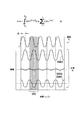
上記の方式が図2に概略的に示される。その図は、電力出力曲線(PO)を示しており、レーザ発振モードが、チャネル周波数中心線200によって指示される所望のチャネルの近くにあるときに、結果として生成される典型的な電力出力曲線を例示する。位相偏移変調方式を用いるサーボループの目的は、レーザ発振周波数が所望のチャネル周波数に向かってシフトするように、レーザ共振器内の1つ又は複数の光学素子を調整することである。これは、レーザ発振モードの周波数変調から生じる復調された誤差信号を用いることにより達成される。その技法のもとで、光路長変調素子112のような、共振器内の光学素子に変調信号が供給され、共振器の光路長が変調される。この変調は、レーザのためのチャネル間隔と比べて相対的に小さい。たとえば、一実施形態では、チャネル間隔は50GHzであるのに対して、その変調は4MHzの偏移を有することができる。
The above scheme is shown schematically in FIG. The figure shows a power output curve (PO), and a typical power output curve that results when the lasing mode is near the desired channel indicated by the
変調された信号202A、202B及び202Cはそれぞれ、(平均)レーザ周波数204A、204B及び204Cに対応する。レーザ周波数204Aは所望のチャネル周波数よりも小さく、レーザ周波数204Cは所望のチャネル周波数よりも大きく、一方、204Bは概ね所望のチャネル周波数である。変調された各信号は、出力ビームの強度内にそれぞれの変調を引き起こす。これらの強度変調はそれぞれ、変調された振幅波形206A、206B及び206Cとして示される。一般的に、強度変調は、出力ビームの強度を決定するべく先に説明されたようにして測定することができる。
図2に示されるように、波形206A、206B及び206Cの山から谷までの振幅は、変調された信号202Aのための交差点208及び210によって示されるような、対応する周波数変調された信号202A、202B及び202Cのための変調の最大偏移が電力出力曲線POと交差する点に直結する。したがって、レーザ周波数が所望のチャネル周波数に接近していくとき、出力ビームの測定された強度の山から谷までの振幅は減少する。レーザ周波数及びチャネル周波数が一致する点では、この値は最小になる。
As shown in FIG. 2, the peak-to-valley amplitudes of
さらに、図3に示されるように、共振器長誤差は以下の式から導出することができる。 Further, as shown in FIG. 3, the resonator length error can be derived from the following equation.

ただし、イタリック体でないiは虚数であり、φは励起入力(すなわち、変調された信号202A、202B及び202C)と、振幅変調された出力波形206A、206B及び206Cを含む応答出力との間の位相差を表し、ωは変調周波数である。時間サンプリング位置300によって示されるような、以下に説明されるタイプのデジタルサーボループに特有の離散時間サンプリング方式によって、積分解を正確に近似することができる。
Where i, which is not italic, is an imaginary number, and φ is the position between the excitation input (ie, modulated
誤差振幅を与えることに加えて、上記の方式は誤差方向も与える。たとえば、レーザ周波数が、所望のチャネル周波数の一方の側(図示される例では下側)にずれているとき、励起及び応答波形は概ね同相になるであろう。これは、正の総計誤差値(aggregated error value)を生成することになる。対照的に、レーザ周波数が、所望のチャネル周波数の他方の側(その例では上側)にあるとき、励起及び応答波形は大きく位相がずれるであろう。結果として、総計誤差値は負になるであろう。 In addition to providing error amplitude, the above scheme also provides error direction. For example, when the laser frequency is shifted to one side of the desired channel frequency (lower in the illustrated example), the excitation and response waveforms will be generally in phase. This will generate a positive aggregated error value. In contrast, when the laser frequency is on the other side of the desired channel frequency (the upper side in the example), the excitation and response waveforms will be greatly out of phase. As a result, the total error value will be negative.
一般的に、変調の波長ロック周波数ωは、レーザ周波数よりも数桁低くなるように選択されるべきである。たとえば、一実施形態では、185〜199THzのレーザ周波数の場合、500Hz〜100kHzの範囲内の変調周波数を用いることができる。 In general, the wavelength lock frequency ω of the modulation should be selected to be several orders of magnitude lower than the laser frequency. For example, in one embodiment, for a laser frequency of 185 to 199 THz, a modulation frequency in the range of 500 Hz to 100 kHz can be used.
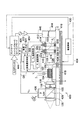
図4には、利得ダイオードチップ102、レンズ108、116及び120等の、同じ参照番号を有する、ECDL100に共通する種々の素子を含むECDL400が示される。チャネル選択サブシステムが、波長選択制御ブロック502を含むことができる。波長選択制御ブロックはコントローラ420の外部に示されるが、このブロックの制御の態様はコントローラ420だけによっても提供できることに留意されたい。波長選択制御ブロック502は、フィルタF1及びF2の温度をそれぞれ制御するための電気的出力504及び506を与える。一実施形態では、温度制御素子は、TEC508及び510によって示されるように、円形のエタロンの外周の周囲に配置される。エタロン温度を制御するべく、フィルタの内部に埋め込まれるヒータを用いることもできる。個々のRTD512及び514を用いて、波長選択制御ブロック502に温度フィードバック信号が戻される。
FIG. 4 shows an
一般的に、レーザ共振器においてエタロンを用いて、フィルタリング機能が提供される。それらのエタロンはファブリペロ共振器として機能する。エタロンの中に光ビームを通す結果として、レーザ出力内に1組の透過ピーク(通過帯域とも呼ばれる)が生成される。透過ピークの間隔(周波数間隔であり、自由スペクトル領域としても知られている)は、エタロンの2つの面間、たとえば、フィルタF1の場合の面516と518との間、及びフィルタF2の場合の面520と522との間の距離に依存する。エタロンの温度が変化すると、エタロン材料が膨張又は収縮するようになり、それゆえ、それらの面間の距離が変化する。これは、エタロンの光路長を実効的に変更し、それを用いて、透過ピークをシフトすることができる。
In general, an etalon is used in a laser resonator to provide a filtering function. These etalons function as Fabry-Perot resonators. As a result of passing the light beam through the etalon, a set of transmission peaks (also called passbands) is generated in the laser output. The transmission peak spacing (frequency spacing, also known as the free spectral region) is between the two faces of the etalon, eg between
フィルタの効果は累積的である。結果として、選択されたチャネルのレーザ発振モードを除く全てのレーザ発振モードを、各フィルタの単一の透過ピークの位置に合わせることによって大きく減衰させることができる。一実施形態では、2エタロンの構成は、エタロンの個々の自由スペクトル領域がわずかに異なるように選択される。これにより、透過ピークが、バーニア目盛によって用いられるのと同じようなバーニアチューニング技法によって位置合わせされるようになる。一実施形態では、「グリッドジェネレータ」として知られている、フィルタのうちの1つは、ITU波長グリッドのような通信チャネルグリッドに対応する自由スペクトル領域を有するように構成され、それらのピークはITUチャネル周波数に位置合わせされる。この波長グリッドは、対応するグリッドジェネレータエタロンの温度を所定の温度に保持することにより、概ね固定されたままになる。同時に、チャネルセレクタとして知られている他方のエタロンの温度は、グリッドジェネレータのピークに対して、その透過ピークをシフトするように調整される。このようにして、フィルタの透過ピークをシフトすることにより、チャネル周波数に対応する透過ピークを位置合わせすることができ、それにより、選択されたチャネル周波数に対応する共振器レーザ発振モードを生成することができる。別の実施形態では、両方のフィルタの透過ピークをシフトして、チャネルを選択することができる。 The effect of the filter is cumulative. As a result, all lasing modes except the lasing mode of the selected channel can be greatly attenuated by matching the position of the single transmission peak of each filter. In one embodiment, the two etalon configuration is selected such that the individual free spectral regions of the etalon are slightly different. This causes the transmission peaks to be aligned by vernier tuning techniques similar to those used by vernier scales. In one embodiment, one of the filters, known as a “grid generator”, is configured to have a free spectral region corresponding to a communication channel grid, such as an ITU wavelength grid, whose peaks are ITU Aligned to the channel frequency. This wavelength grid remains generally fixed by keeping the temperature of the corresponding grid generator etalon at a predetermined temperature. At the same time, the temperature of the other etalon, known as the channel selector, is adjusted to shift its transmission peak relative to the grid generator peak. In this way, by shifting the transmission peak of the filter, the transmission peak corresponding to the channel frequency can be aligned, thereby generating a resonator lasing mode corresponding to the selected channel frequency. Can do. In another embodiment, the transmission peaks of both filters can be shifted to select a channel.
一般的に、これらの方式のいずれも、参照テーブル524によって示されるような、対応するチャネルのためのエタロン温度が記憶されるチャネル−エタロンフィルタ温度参照テーブルを用いることにより実施することができる。典型的には、参照テーブル内のエタロン温度/チャネル値は、較正手順によって求めることができるか、統計データによって求めることができるか、又はチューニングデータに適合するチューニング関数に基づいて計算することができる。入力チャネル選択444に応答して、対応するエタロン温度が参照テーブル524から検索され、当該技術分野においてよく知られている適当な温度制御ループを用いるエタロンのためのターゲット温度として用いられる。
In general, any of these schemes can be implemented by using a channel-etalon filter temperature lookup table in which the etalon temperature for the corresponding channel is stored, as shown by lookup table 524. Typically, the etalon temperature / channel values in the lookup table can be determined by a calibration procedure, can be determined by statistical data, or can be calculated based on a tuning function that fits the tuning data. . In response to
ECDL400はさらに、反射性背面414を有する共振器光路長変調素子412を含むことができる。より具体的には、共振器光路長変調素子は、ニオブ酸リチウム(LiNbO3)位相変調器を含み、その変調器に背面鏡が結合される。オプションでは、反射材料を位相変調器の背面にコーティングすることができる。ニオブ酸リチウムは、電圧が印加されるときに、その屈折率(材料内の光の速さを真空中の光の速さで割った比)を変更する材料である。結果として、LiNbO3位相変調器に対して、変調された電圧信号を供給することにより、外部レーザ共振器の光路長を変調又は「ディザリング」することができ、それにより、先に説明された信号202A、202B及び202Cのような周波数変調された信号を生成することができる。
The
ECDL400の種々の光学部品は、熱制御可能な台又は「そり」416に実装又はそれ以外の方法で結合される。一実施形態では、ペルチエ素子のような、1つ又は複数の熱電冷却器(TEC)素子418が、入力電気信号を介してそりの温度を正確に制御できるように、そり416に取り付けられるか、又はそり416に組み込まれる。温度変化に応答する材料の膨張及び収縮によって、そりの長さは非常に正確に調整することができる。長さを調整する結果として、部分反射性の前面ファセット104と反射素子414との間の距離が変化するようになり、レーザ共振器の光路長の変化が生み出される。結果として、そりの温度を制御することにより、レーザ発振モードの周波数を調整することができる。一般的に、そりの温度制御は非常に細かいチューニング調整を目的として用いられ、一方、以下にさらに詳細に説明されるように、チューニングフィルタ素子110によって、それよりも粗いチューニング調整が行われるであろう。
The various optical components of
波長をロックするべく、コントローラ420が変調された、又は「ディザリングされた」波長ロック信号422を生成し、それが増幅器424によって増幅される。たとえば、一実施形態では、変調された波長ロック信号422は、周波数が約889Hzの2Vp−p信号のような、一定の周波数を有する正弦波を含むことができる。その後、増幅された変調波長ロック信号は、LiNbO3位相変調器412の表面に供給され、一方、反対の表面は接地され、それによりLiNbO3材料の両端に電圧差が与えられる。結果として、変調器の光路長、それゆえレーザ共振器全体が変調周波数(たとえば889Hz)で変調される。一実施形態では、2Vp−p電圧差の結果として、約4MHzの周波数偏位が生成される。
To lock the wavelength,
この光路長変調は、出力ビーム122の強度の変調を引き起こし、一実施形態では、その変調は光検出器426によって検出される。図4に示されるように、ビームスプリッタ428が出力ビーム122の光路内に配置され、出力ビーム光の一部が光検出器426に向かって誘導されるようにする。一実施形態では、光検出器426はフォトダイオードを含み、それは受光する光の強度(hvdet)に応答して電圧変化を生み出す。その後、対応する電圧VPDがコントローラ420にフィードバックされる。オプションの一実施形態では、VPDではなく、利得ダイオードチップにかかる接合部電圧(VJ)が強度フィードバック信号として用いられる。その後、図3を参照して先に説明されたような共振器長誤差信号が、変調された波長ロック信号422とともに、VPD又はVJの振幅変調及び位相に基づいて導出される。
This optical path length modulation causes a modulation of the intensity of the
コントローラ420は、図2及び図3を参照して先に説明された周波数変調方式に従って、そり416の温度を調整するように構成され、共振器長誤差信号が最小限に抑えられるようにするデジタルサーボループを含む。誤差信号に応答して、温度制御信号430の適当な調整値が生成される。そり温度を調整するのに応じて、共振器長全体の変化、それゆえレーザ発振周波数の変化が生じる。この結果としてさらに(理想的には)、レーザ発振周波数と所望のチャネル周波数との間の差が減少し、それにより制御ループが完成する。初期状態に達するべく、又はそり温度を制御するべく、抵抗性の熱デバイス(RTD)434、すなわちサーミスタ又は熱電対を用いて、コントローラ420に温度フィードバック信号434を与えることができる。
The
チューナブルレーザをターゲット周波数(すなわち、新たなチャネル)にチューニングするとき、その動作に対して、チューニング速度及び周波数安定性の両方が非常に重要である。本発明の実施形態は、速度及び周波数安定性の両方を改善するための解決手段を提供する。 When tuning a tunable laser to a target frequency (ie, a new channel), both tuning speed and frequency stability are very important for its operation. Embodiments of the present invention provide a solution for improving both speed and frequency stability.
ECDL400を新たな周波数(チャネル)に最初にチューニングするとき、共振器長は、図2に示されるように、丘(PO)のいずれかの側にあり、透過曲線のピークに到達するべく動かされる。一実施形態によれば、コントローラ420は、ハイバンド幅モード及びローバンド幅モードを含む。この最初の時間では、ハイバンド幅コントローラモードを用いて、そりTEC418のようなアクチュエータに、より多くのエネルギーを供給し、より速い速度の探索を達成することができる。共振器長誤差信号が所定の閾値内に接近するとき、コントローラをローバンド幅コントローラモードに切り替えて、ターゲット(透過曲線のピーク)に接近し、そのピークにおいてロックを保持することができる。この追従モードでは、ローバンド幅コントローラは、雑音レベルを低くしておくことができ、チューナブルレーザに、より良好な周波数安定性を与える。
When the
可変帯域幅コントローラを用いることによって得られる改善が、図5及び図6に示される時間応答の図を比較することにより例示される。図5は、共振器ロック過程のトレースの一例であり、単一の帯域幅コントローラが用いられる場合を例示する。図5の上側のグラフは、共振器ロック過程中の時間に対して誤差信号612をプロットする。誤差信号のゼロ点は、透過曲線のピークに対応する。図5の下側のグラフは、チューナブルレーザの共振器長を制御するTEC418の温度を示す。図に示されるように、単一の帯域幅モードコントローラを用いるときでも、最終的にはターゲットに到達して、その誤差信号が概ねゼロ付近に保持される。この例では、サーボ制御によってターゲットに達するのに約3秒かかる。
The improvement obtained by using a variable bandwidth controller is illustrated by comparing the time response diagrams shown in FIGS. FIG. 5 is an example of a trace of the resonator lock process and illustrates the case where a single bandwidth controller is used. The upper graph of FIG. 5 plots the
図6は、可変帯域幅コントローラが用いられる場合を示しており、本発明の実施形態による共振器ロック過程のトレースを示す。探索段階では、コントローラ420のハイバンド幅モードによって、そりTEC418の温度が、極めて急速に上昇できるようになる。しかしながら、一部を取り出した図80に示されるように、誤差信号がゼロに接近するとき、コントローラ420が、ローバンド幅フィルタ又はモードを用いる追従モードに切り替わり、誤差信号が緩やかにゼロに接近し、ターゲット周波数のオーバーシュートが避けられるようにする。さらに、追従モードにおいてローバンド幅コントローラを用いるとき、定常状態では、チューナブルレーザの周波数安定性が改善され、誤差信号が概ね0に保持される。この例では、コントローラ420は、誤差信号の絶対値が0.03よりも大きいときに探索モードにあり、誤差信号が±0.03の閾値範囲内にあるときに追従モードに切り替わる。当然、これは単なる一例であり、その範囲は、レーザの応用形態及び動作の許容範囲によって広くも狭くもすることができる。多モードコントローラ420は、リード/ラグコントローラ又はPID(比例積分微分)コントローラのようないくつかのコントローラ方式のうちの任意のものによって実現することができる。探索モードでは、バンバン又は類似の開ループコントローラを用いることもできる。探索モードでは、ハイバンド幅モードのコントローラ420が、より大きな電力を用いて、TEC418を駆動することができるとき、たとえば、その駆動電力は約2又は3ワットにすることができるのに対して、追従モードでは、ローバンド幅モードのコントローラが、電力を削減して、たとえば約0.1〜0.2ワットでTEC418を駆動することができる。
FIG. 6 illustrates the case where a variable bandwidth controller is used and shows a trace of the resonator lock process according to an embodiment of the present invention. In the search phase, the high bandwidth mode of the
図6に示されるように、2モードコントローラを用いるとき、図5と同じチューナブルレーザを同じ周波数にロックするのに、約1.7秒しかかからない。こうして、2モードコントローラを用いることにより、チューナブルレーザの速度と周波数安定性との間で妥協を図る必要はない。それゆえ、探索用サーボ及び追従用サーボがいずれも同時に最適化され、チューナブルレーザの性能を大幅に改善することができる。 As shown in FIG. 6, when using a two-mode controller, it takes only about 1.7 seconds to lock the same tunable laser as in FIG. 5 to the same frequency. Thus, by using a two-mode controller, there is no need to compromise between tunable laser speed and frequency stability. Therefore, both the search servo and the tracking servo are optimized at the same time, and the performance of the tunable laser can be greatly improved.
チューナブルレーザの共振器ロックサーボに関する実施形態が説明されてきたが、説明された技法は、チューナブルフィルタのエタロン(図4のF1及びF2)の温度制御においても用いることができる。チューナブルレーザ内のエタロンの温度制御を用いて、透過曲線が所望の周波数に動かされる。この技法は、異なるタイプのアクチュエータを用いて要求される周波数にチューニングする、全ての他のタイプのチューナブルレーザにも適用することができる。 Although embodiments have been described for tunable laser resonator lock servos, the described techniques can also be used in temperature control of the tunable filter etalon (F1 and F2 in FIG. 4). Using the temperature control of the etalon in the tunable laser, the transmission curve is moved to the desired frequency. This technique can also be applied to all other types of tunable lasers that are tuned to the required frequency using different types of actuators.
要約書に記載される内容を含む、本発明の例示される実施形態の上記の説明は、本発明を包括的に述べること、又は本発明を開示されるのと全く同じ形態に限定することは意図していない。本発明の具体的な実施形態、及び本発明の実施例が、本明細書において説明されてきたが、本発明の範囲内で、種々の同等の変更が可能であることは、当業者には理解されよう。 The above description of illustrated embodiments of the invention, including what is described in the abstract, does not comprehensively describe the invention or limit the invention to the exact form disclosed. Not intended. While specific embodiments of the present invention and examples of the present invention have been described herein, those skilled in the art will recognize that various equivalent modifications are possible within the scope of the present invention. It will be understood.
上記の詳細な説明を踏まえて、本発明に対して、これらの変更を行うことができる。添付の特許請求の範囲において用いられる用語は、本発明を明細書及び特許請求の範囲において開示される具体的な実施形態に限定するものと解釈されるべきではない。むしろ、本発明の範囲は、添付の特許請求の範囲によって完全に決定されるべきであり、特許請求の範囲は、既に確立されている特許請求の範囲の解釈論に基づいて解釈されるべきである。 These modifications can be made to the invention in light of the above detailed description. The terms used in the following claims should not be construed to limit the invention to the specific embodiments disclosed in the specification and the claims. Rather, the scope of the invention should be determined entirely by the appended claims, which should be construed on the basis of the established claims interpretation. is there.
Claims (23)
チューナブルレーザのチューニング素子を駆動するためのアクチュエータと、
ハイバンド幅モード及びローバンド幅モードを含む多帯域幅モードコントローラとを備え、
前記コントローラは最初に、前記ハイバンド幅モードにおいて前記アクチュエータを駆動し、ターゲット周波数に関する誤差信号が閾値範囲内に入るときに、前記ローバンド幅モードに切り替わる、チューナブルレーザ。 A tunable laser,
An actuator for driving the tuning element of the tunable laser;
A multi-bandwidth mode controller including a high bandwidth mode and a low bandwidth mode,
The controller first drives the actuator in the high bandwidth mode and switches to the low bandwidth mode when an error signal related to a target frequency falls within a threshold range.
前記レーザの共振器長をディザリングすることであって、それによってターゲット周波数を得るための透過ピーク誤差信号を生成する、ディザリングすること、
アクチュエータを第1の電力レベルにおいて駆動することであって、それによって前記誤差信号をゼロに向かって動かす、駆動すること、及び
前記誤差信号が概ねゼロの閾値範囲内に入るときに、前記アクチュエータを、前記第1の電力レベルよりも低い第2の電力レベルにおいて駆動することを含む、レーザをチューニングする方法。 A method for tuning a laser,
Dithering the cavity length of the laser, thereby generating a transmission peak error signal to obtain a target frequency;
Driving the actuator at a first power level, thereby moving the error signal toward zero, and driving the actuator when the error signal falls within a substantially zero threshold range. A method of tuning a laser comprising driving at a second power level that is lower than the first power level.
外部共振器ダイオードレーザ(ECDL)と、
前記ECDLのチューニング素子を駆動するためのアクチュエータと、
新たなターゲット周波数を探索するためのハイバンド幅モードと、該ターゲット周波数に追従するためのローバンド幅モードとを含む多帯域幅モードコントローラとを備え、
前記コントローラは最初に、前記ハイバンド幅モードにおいて前記アクチュエータを駆動し、その後、ターゲット周波数に関する誤差信号が閾値範囲内に入るときに、前記ローバンド幅モードにおいて駆動する、システム。 A system,
An external cavity diode laser (ECDL);
An actuator for driving the ECDL tuning element;
A multi-bandwidth mode controller including a high-bandwidth mode for searching for a new target frequency and a low-bandwidth mode for tracking the target frequency;
The controller first drives the actuator in the high bandwidth mode and then drives in the low bandwidth mode when an error signal related to a target frequency falls within a threshold range.
Applications Claiming Priority (2)
| Application Number | Priority Date | Filing Date | Title |
|---|---|---|---|
| US10/659,958 US20050053103A1 (en) | 2003-09-10 | 2003-09-10 | Seeking and tracking control for locking to transmision peak for a tunable laser |
| PCT/US2004/028730 WO2005027286A1 (en) | 2003-09-10 | 2004-09-03 | Seeking and tracking control for locking to transmision peak for a tunable laser |
Publications (1)
| Publication Number | Publication Date |
|---|---|
| JP2007505496A true JP2007505496A (en) | 2007-03-08 |
Family
ID=34227019
Family Applications (1)
| Application Number | Title | Priority Date | Filing Date |
|---|---|---|---|
| JP2006526192A Pending JP2007505496A (en) | 2003-09-10 | 2004-09-03 | Search and tracking control to lock to transmission peak for tunable lasers |
Country Status (6)
| Country | Link |
|---|---|
| US (1) | US20050053103A1 (en) |
| EP (1) | EP1671404A1 (en) |
| JP (1) | JP2007505496A (en) |
| CN (1) | CN1849733A (en) |
| TW (1) | TWI279951B (en) |
| WO (1) | WO2005027286A1 (en) |
Cited By (4)
| Publication number | Priority date | Publication date | Assignee | Title |
|---|---|---|---|---|
| JP2009031238A (en) * | 2007-06-29 | 2009-02-12 | Optical Comb Inc | Optical coherence tomography device |
| JP2012033895A (en) * | 2010-06-30 | 2012-02-16 | Furukawa Electric Co Ltd:The | Semiconductor laser module and control method thereof |
| JP2013179266A (en) * | 2012-01-30 | 2013-09-09 | Agilent Technologies Inc | Phase-continuous tunable laser |
| KR101382724B1 (en) | 2012-12-28 | 2014-04-08 | 한국항공우주연구원 | Apparatus and method for adaptive proportional-integral control of angular velocity |
Families Citing this family (21)
| Publication number | Priority date | Publication date | Assignee | Title |
|---|---|---|---|---|
| KR100532303B1 (en) * | 2003-11-15 | 2005-11-29 | 삼성전자주식회사 | Multi channel optical light source and multi channel optical module using the same |
| US20050123008A1 (en) * | 2003-12-08 | 2005-06-09 | Daiber Andrew J. | Multiple input/output ECDL cavity length and filter temperature control |
| US7565084B1 (en) | 2004-09-15 | 2009-07-21 | Wach Michael L | Robustly stabilizing laser systems |
| US20070002924A1 (en) * | 2005-06-30 | 2007-01-04 | Hutchinson John M | Integrated monitoring and feedback designs for external cavity tunable lasers |
| CN101350821B (en) * | 2008-09-04 | 2013-06-26 | 华为技术有限公司 | Dual mode storing method and apparatus |
| KR101087263B1 (en) * | 2009-12-24 | 2011-11-29 | 한국과학기술원 | A Device and Method for Controlling Lasing Wavelengths of Tunable Laser Source, and A Wavelength Division Multiplexed-Passive Optical Network Having the Same |
| CN102162913A (en) * | 2011-04-14 | 2011-08-24 | 福州高意通讯有限公司 | Tunable filter |
| WO2015042693A1 (en) * | 2013-09-26 | 2015-04-02 | Kumarakrishnan Anantharaman | Apparatus and methods for controlling the output frequency of a laser |
| CN104242051B (en) * | 2014-09-18 | 2017-05-10 | 武汉光迅科技股份有限公司 | External cavity tunable laser and cavity mode locking method thereof |
| CN106209196B (en) * | 2016-06-30 | 2019-11-12 | 广州海格通信集团股份有限公司 | A kind of phase compensating method and system based on more array element channel selections |
| CN106953232B (en) * | 2017-05-16 | 2023-08-29 | 深圳新飞通光电子技术有限公司 | Dual-wavelength tunable laser, dual-wavelength tunable laser system and method for realizing rapid frequency modulation |
| CN109193332B (en) * | 2018-08-24 | 2019-08-16 | 武汉光迅科技股份有限公司 | A kind of compensation method of laser output frequency and corresponding optical module |
| CN110888245B (en) | 2018-09-10 | 2023-09-22 | 苏州旭创科技有限公司 | Wavelength selection method and wavelength selection device for tunable laser |
| US11018474B2 (en) * | 2018-11-30 | 2021-05-25 | Optella Inc. | Laser temperature compensation system and driving method thereof |
| CN112397995B (en) * | 2019-08-02 | 2022-02-15 | 苏州旭创科技有限公司 | Narrow-linewidth fixed-wavelength laser and optical module |
| CN112310807A (en) * | 2019-08-02 | 2021-02-02 | 苏州旭创科技有限公司 | External cavity tunable laser and optical module |
| CN112310805A (en) * | 2019-08-02 | 2021-02-02 | 苏州旭创科技有限公司 | Narrow-linewidth external cavity laser and optical module |
| CN112397993A (en) * | 2019-08-02 | 2021-02-23 | 苏州旭创科技有限公司 | Narrow-linewidth external cavity laser and optical module |
| CN113588101B (en) * | 2020-04-30 | 2023-05-02 | 北京科益虹源光电技术有限公司 | Absolute wavelength calibration method of excimer laser |
| CN111555108A (en) * | 2020-05-14 | 2020-08-18 | 山西大学 | High-stability Fabry-Perot cavity device and laser output system applying same |
| CN113410753A (en) * | 2021-06-10 | 2021-09-17 | 深圳市大族光通科技有限公司 | Adjustable laser adjusting circuit and adjusting system |
Family Cites Families (15)
| Publication number | Priority date | Publication date | Assignee | Title |
|---|---|---|---|---|
| US6111681A (en) * | 1996-02-23 | 2000-08-29 | Ciena Corporation | WDM optical communication systems with wavelength-stabilized optical selectors |
| DE19620594A1 (en) * | 1996-05-22 | 1997-11-27 | Sel Alcatel Ag | Resonator for electromagnetic waves with a stabilizing device and method for stabilizing the resonator length |
| US6222861B1 (en) * | 1998-09-03 | 2001-04-24 | Photonic Solutions, Inc. | Method and apparatus for controlling the wavelength of a laser |
| US6516010B1 (en) * | 1999-07-13 | 2003-02-04 | Agere Systems, Inc. | Method and apparatus for active numeric temperature compensation of an etalon in a wavelength stabilized laser |
| US6853654B2 (en) * | 1999-07-27 | 2005-02-08 | Intel Corporation | Tunable external cavity laser |
| DE60034068T2 (en) * | 1999-08-13 | 2007-12-06 | California Institute Of Technology, Pasadena | Frequency locking device in a fiber |
| US6359915B1 (en) * | 1999-09-23 | 2002-03-19 | Agere Systems | Wavelength-stabilized Bragg laser |
| US6788719B2 (en) * | 2000-05-04 | 2004-09-07 | Agility Communications, Inc. | Open loop control of SGDBR lasers |
| US7120176B2 (en) * | 2000-07-27 | 2006-10-10 | Intel Corporation | Wavelength reference apparatus and method |
| AU2002239600A1 (en) * | 2000-12-14 | 2002-06-24 | Sri International | Dense wavelength division multiplexing (dwdm) fiberoptic source |
| US7054242B2 (en) * | 2001-01-25 | 2006-05-30 | Dphi Acquisitions, Inc. | System and method for controlling focus in an optical disc drive |
| US6631146B2 (en) * | 2001-07-06 | 2003-10-07 | Intel Corporation | Tunable laser control system |
| US20030033819A1 (en) * | 2001-08-10 | 2003-02-20 | Prescott Daniel C. | Current-Mode control of Thermo-Electric cooler |
| US7151789B2 (en) * | 2002-12-20 | 2006-12-19 | Spectalis Corp | External-cavity lasers |
| US6661814B1 (en) * | 2002-12-31 | 2003-12-09 | Intel Corporation | Method and apparatus for suppressing stimulated brillouin scattering in fiber links |
-
2003
- 2003-09-10 US US10/659,958 patent/US20050053103A1/en not_active Abandoned
-
2004
- 2004-09-03 EP EP04783089A patent/EP1671404A1/en not_active Ceased
- 2004-09-03 WO PCT/US2004/028730 patent/WO2005027286A1/en active Application Filing
- 2004-09-03 JP JP2006526192A patent/JP2007505496A/en active Pending
- 2004-09-03 CN CNA2004800257566A patent/CN1849733A/en active Pending
- 2004-09-09 TW TW093127275A patent/TWI279951B/en not_active IP Right Cessation
Cited By (4)
| Publication number | Priority date | Publication date | Assignee | Title |
|---|---|---|---|---|
| JP2009031238A (en) * | 2007-06-29 | 2009-02-12 | Optical Comb Inc | Optical coherence tomography device |
| JP2012033895A (en) * | 2010-06-30 | 2012-02-16 | Furukawa Electric Co Ltd:The | Semiconductor laser module and control method thereof |
| JP2013179266A (en) * | 2012-01-30 | 2013-09-09 | Agilent Technologies Inc | Phase-continuous tunable laser |
| KR101382724B1 (en) | 2012-12-28 | 2014-04-08 | 한국항공우주연구원 | Apparatus and method for adaptive proportional-integral control of angular velocity |
Also Published As
| Publication number | Publication date |
|---|---|
| WO2005027286A1 (en) | 2005-03-24 |
| CN1849733A (en) | 2006-10-18 |
| US20050053103A1 (en) | 2005-03-10 |
| EP1671404A1 (en) | 2006-06-21 |
| TW200514322A (en) | 2005-04-16 |
| TWI279951B (en) | 2007-04-21 |
Similar Documents
| Publication | Publication Date | Title |
|---|---|---|
| JP2007505496A (en) | Search and tracking control to lock to transmission peak for tunable lasers | |
| US6665321B1 (en) | Tunable laser operation with locally commensurate condition | |
| US6661815B1 (en) | Servo technique for concurrent wavelength locking and stimulated brillouin scattering suppression | |
| US7257142B2 (en) | Semi-integrated designs for external cavity tunable lasers | |
| US6661814B1 (en) | Method and apparatus for suppressing stimulated brillouin scattering in fiber links | |
| CA2720036C (en) | Method and apparatus for reducing the amplitude modulation of optical signals in external cavity lasers | |
| KR100821651B1 (en) | External cavity laser apparatus with orthogonal tuning of laser wavelength and cavity optical path length | |
| US6822979B2 (en) | External cavity laser with continuous tuning of grid generator | |
| US6289028B1 (en) | Method and apparatus for monitoring and control of laser emission wavelength | |
| US6763047B2 (en) | External cavity laser apparatus and methods | |
| US9298023B2 (en) | Optical beam steering for tunable laser applications | |
| JP4992073B2 (en) | Phase control of an external cavity tunable laser. | |
| US6667998B1 (en) | Thermoelectric cooler linearization in a tunable laser | |
| US20030016707A1 (en) | Wavelength reference apparatus and method | |
| JP4596181B2 (en) | External cavity tunable semiconductor laser | |
| US6724790B1 (en) | Laser facet phase control | |
| US6560253B1 (en) | Method and apparatus for monitoring and control of laser emission wavelength | |
| US20050123008A1 (en) | Multiple input/output ECDL cavity length and filter temperature control | |
| US6816517B2 (en) | Micro-electromechanical devices for wavelength tunable lasers | |
| US20090086774A1 (en) | Control device, laser device, wavelength converting method, and program | |
| US6687269B1 (en) | Spread spectrum dither for locking to transmission peak in tunable laser | |
| US20050111498A1 (en) | Mode behavior of single-mode semiconductor lasers | |
| JP2008241953A (en) | Wavelength selection reflective circuit and multi-wavelength light source |
Legal Events
| Date | Code | Title | Description |
|---|---|---|---|
| A131 | Notification of reasons for refusal |
Free format text: JAPANESE INTERMEDIATE CODE: A131 Effective date: 20080624 |
|
| A601 | Written request for extension of time |
Free format text: JAPANESE INTERMEDIATE CODE: A601 Effective date: 20080922 |
|
| A602 | Written permission of extension of time |
Free format text: JAPANESE INTERMEDIATE CODE: A602 Effective date: 20080930 |
|
| A601 | Written request for extension of time |
Free format text: JAPANESE INTERMEDIATE CODE: A601 Effective date: 20081023 |
|
| A602 | Written permission of extension of time |
Free format text: JAPANESE INTERMEDIATE CODE: A602 Effective date: 20081030 |
|
| A601 | Written request for extension of time |
Free format text: JAPANESE INTERMEDIATE CODE: A601 Effective date: 20081121 |
|
| A602 | Written permission of extension of time |
Free format text: JAPANESE INTERMEDIATE CODE: A602 Effective date: 20081201 |
|
| A521 | Request for written amendment filed |
Free format text: JAPANESE INTERMEDIATE CODE: A523 Effective date: 20081224 |
|
| A131 | Notification of reasons for refusal |
Free format text: JAPANESE INTERMEDIATE CODE: A131 Effective date: 20090324 |
|
| A521 | Request for written amendment filed |
Free format text: JAPANESE INTERMEDIATE CODE: A523 Effective date: 20090624 |
|
| A02 | Decision of refusal |
Free format text: JAPANESE INTERMEDIATE CODE: A02 Effective date: 20091222 |