JP2007504885A - Devices, systems and methods for suturing tissue - Google Patents
Devices, systems and methods for suturing tissue Download PDFInfo
- Publication number
- JP2007504885A JP2007504885A JP2006526055A JP2006526055A JP2007504885A JP 2007504885 A JP2007504885 A JP 2007504885A JP 2006526055 A JP2006526055 A JP 2006526055A JP 2006526055 A JP2006526055 A JP 2006526055A JP 2007504885 A JP2007504885 A JP 2007504885A
- Authority
- JP
- Japan
- Prior art keywords
- tissue
- tissue engaging
- engaging member
- suturing
- interconnecting
- Prior art date
- Legal status (The legal status is an assumption and is not a legal conclusion. Google has not performed a legal analysis and makes no representation as to the accuracy of the status listed.)
- Pending
Links
Images


Classifications
-
- A—HUMAN NECESSITIES
- A61—MEDICAL OR VETERINARY SCIENCE; HYGIENE
- A61B—DIAGNOSIS; SURGERY; IDENTIFICATION
- A61B17/00—Surgical instruments, devices or methods, e.g. tourniquets
- A61B17/0057—Implements for plugging an opening in the wall of a hollow or tubular organ, e.g. for sealing a vessel puncture or closing a cardiac septal defect
-
- A—HUMAN NECESSITIES
- A61—MEDICAL OR VETERINARY SCIENCE; HYGIENE
- A61B—DIAGNOSIS; SURGERY; IDENTIFICATION
- A61B17/00—Surgical instruments, devices or methods, e.g. tourniquets
- A61B17/04—Surgical instruments, devices or methods, e.g. tourniquets for suturing wounds; Holders or packages for needles or suture materials
- A61B17/0401—Suture anchors, buttons or pledgets, i.e. means for attaching sutures to bone, cartilage or soft tissue; Instruments for applying or removing suture anchors
-
- A—HUMAN NECESSITIES
- A61—MEDICAL OR VETERINARY SCIENCE; HYGIENE
- A61B—DIAGNOSIS; SURGERY; IDENTIFICATION
- A61B17/00—Surgical instruments, devices or methods, e.g. tourniquets
- A61B17/064—Surgical staples, i.e. penetrating the tissue
- A61B17/0644—Surgical staples, i.e. penetrating the tissue penetrating the tissue, deformable to closed position
-
- A—HUMAN NECESSITIES
- A61—MEDICAL OR VETERINARY SCIENCE; HYGIENE
- A61B—DIAGNOSIS; SURGERY; IDENTIFICATION
- A61B17/00—Surgical instruments, devices or methods, e.g. tourniquets
- A61B17/068—Surgical staplers, e.g. containing multiple staples or clamps
-
- A—HUMAN NECESSITIES
- A61—MEDICAL OR VETERINARY SCIENCE; HYGIENE
- A61B—DIAGNOSIS; SURGERY; IDENTIFICATION
- A61B17/00—Surgical instruments, devices or methods, e.g. tourniquets
- A61B17/00234—Surgical instruments, devices or methods, e.g. tourniquets for minimally invasive surgery
- A61B2017/00238—Type of minimally invasive operation
- A61B2017/00243—Type of minimally invasive operation cardiac
-
- A—HUMAN NECESSITIES
- A61—MEDICAL OR VETERINARY SCIENCE; HYGIENE
- A61B—DIAGNOSIS; SURGERY; IDENTIFICATION
- A61B17/00—Surgical instruments, devices or methods, e.g. tourniquets
- A61B17/0057—Implements for plugging an opening in the wall of a hollow or tubular organ, e.g. for sealing a vessel puncture or closing a cardiac septal defect
- A61B2017/00575—Implements for plugging an opening in the wall of a hollow or tubular organ, e.g. for sealing a vessel puncture or closing a cardiac septal defect for closure at remote site, e.g. closing atrial septum defects
- A61B2017/00579—Barbed implements
-
- A—HUMAN NECESSITIES
- A61—MEDICAL OR VETERINARY SCIENCE; HYGIENE
- A61B—DIAGNOSIS; SURGERY; IDENTIFICATION
- A61B17/00—Surgical instruments, devices or methods, e.g. tourniquets
- A61B17/0057—Implements for plugging an opening in the wall of a hollow or tubular organ, e.g. for sealing a vessel puncture or closing a cardiac septal defect
- A61B2017/00575—Implements for plugging an opening in the wall of a hollow or tubular organ, e.g. for sealing a vessel puncture or closing a cardiac septal defect for closure at remote site, e.g. closing atrial septum defects
- A61B2017/00592—Elastic or resilient implements
-
- A—HUMAN NECESSITIES
- A61—MEDICAL OR VETERINARY SCIENCE; HYGIENE
- A61B—DIAGNOSIS; SURGERY; IDENTIFICATION
- A61B17/00—Surgical instruments, devices or methods, e.g. tourniquets
- A61B17/0057—Implements for plugging an opening in the wall of a hollow or tubular organ, e.g. for sealing a vessel puncture or closing a cardiac septal defect
- A61B2017/00575—Implements for plugging an opening in the wall of a hollow or tubular organ, e.g. for sealing a vessel puncture or closing a cardiac septal defect for closure at remote site, e.g. closing atrial septum defects
- A61B2017/00606—Implements H-shaped in cross-section, i.e. with occluders on both sides of the opening
-
- A—HUMAN NECESSITIES
- A61—MEDICAL OR VETERINARY SCIENCE; HYGIENE
- A61B—DIAGNOSIS; SURGERY; IDENTIFICATION
- A61B17/00—Surgical instruments, devices or methods, e.g. tourniquets
- A61B17/0057—Implements for plugging an opening in the wall of a hollow or tubular organ, e.g. for sealing a vessel puncture or closing a cardiac septal defect
- A61B2017/00575—Implements for plugging an opening in the wall of a hollow or tubular organ, e.g. for sealing a vessel puncture or closing a cardiac septal defect for closure at remote site, e.g. closing atrial septum defects
- A61B2017/0061—Implements located only on one side of the opening
-
- A—HUMAN NECESSITIES
- A61—MEDICAL OR VETERINARY SCIENCE; HYGIENE
- A61B—DIAGNOSIS; SURGERY; IDENTIFICATION
- A61B17/00—Surgical instruments, devices or methods, e.g. tourniquets
- A61B17/04—Surgical instruments, devices or methods, e.g. tourniquets for suturing wounds; Holders or packages for needles or suture materials
- A61B17/0401—Suture anchors, buttons or pledgets, i.e. means for attaching sutures to bone, cartilage or soft tissue; Instruments for applying or removing suture anchors
- A61B2017/0409—Instruments for applying suture anchors
-
- A—HUMAN NECESSITIES
- A61—MEDICAL OR VETERINARY SCIENCE; HYGIENE
- A61B—DIAGNOSIS; SURGERY; IDENTIFICATION
- A61B17/00—Surgical instruments, devices or methods, e.g. tourniquets
- A61B17/04—Surgical instruments, devices or methods, e.g. tourniquets for suturing wounds; Holders or packages for needles or suture materials
- A61B17/0401—Suture anchors, buttons or pledgets, i.e. means for attaching sutures to bone, cartilage or soft tissue; Instruments for applying or removing suture anchors
- A61B2017/0419—H-fasteners
Landscapes
- Health & Medical Sciences (AREA)
- Life Sciences & Earth Sciences (AREA)
- Surgery (AREA)
- Molecular Biology (AREA)
- General Health & Medical Sciences (AREA)
- Biomedical Technology (AREA)
- Heart & Thoracic Surgery (AREA)
- Medical Informatics (AREA)
- Nuclear Medicine, Radiotherapy & Molecular Imaging (AREA)
- Animal Behavior & Ethology (AREA)
- Engineering & Computer Science (AREA)
- Public Health (AREA)
- Veterinary Medicine (AREA)
- Rheumatology (AREA)
- Cardiology (AREA)
- Surgical Instruments (AREA)
- Materials For Medical Uses (AREA)
Abstract
本発明は、患者の組織のような生物学的材料を経皮的に縫合するためのデバイス、システム、および方法に関する。1つの実施形態において、縫合デバイスは、第1の相互連結部材(144)により互いに連結される第1の組織係合部材(140)および第2の組織係合部材(142)を含む。別の実施形態において、組織の2つの重なる層(60、62)を通して穴を形成するためのシステムおよび方法が提供される。組織の2つの層を通して穴を形成することに引き続いて、この縫合デバイスは、重なる組織の2つの層と結合またはそれに接触するように、その穴を通して配置される。The present invention relates to devices, systems, and methods for percutaneously suturing biological material such as patient tissue. In one embodiment, the suturing device includes a first tissue engaging member (140) and a second tissue engaging member (142) that are connected to each other by a first interconnecting member (144). In another embodiment, a system and method are provided for forming a hole through two overlapping layers (60, 62) of tissue. Subsequent to forming the hole through the two layers of tissue, the suturing device is positioned through the hole to couple or contact the two layers of overlapping tissue.
Description
(関連出願の相互参照)
本出願は、米国仮出願第60/501,948号(2003年9月11日出願)を参考として援用し、そしてそれに基づく優先権およびその利益を主張する。
(Cross-reference of related applications)
This application incorporates US Provisional Application No. 60 / 501,948 (filed Sep. 11, 2003) as a reference and claims priority and benefits based thereon.
(技術分野)
本発明は、概して、経皮的に組織を縫合するためのデバイス、システムおよび方法に関する。より具体的には、本発明は、相互連結部材によって互いに連結された少なくとも2つの組織係合部材を含む縫合デバイスに関する。
(Technical field)
The present invention generally relates to devices, systems and methods for percutaneously suturing tissue. More specifically, the present invention relates to a suturing device that includes at least two tissue engaging members coupled together by an interconnecting member.
(背景)
中隔は、一般に、2つ以上の身体上の空間の間の分ける筋肉壁、膜、または組織として定義される。例えば、ヒトの心臓は、4つの区画または室に分けられている。左心房および右心房は、心臓の上方部分に位置し、左心室および右心室は心臓の下方部分に位置している。左心房および右心房は、心房間中隔により互いから隔てられており、他方、心室は、心室内中隔により隔てられている。
(background)
The septum is generally defined as the muscle wall, membrane, or tissue that divides between two or more body spaces. For example, the human heart is divided into four compartments or chambers. The left and right atria are located in the upper part of the heart, and the left and right ventricles are located in the lower part of the heart. The left and right atria are separated from each other by an interatrial septum, while the ventricles are separated by an intraventricular septum.
中隔の欠陥は、種々の形態を採り得る。例示的な中隔の欠陥は、開存卵円孔である。開存卵円孔は、持続性があり、一方通行であり、通常は、心臓の右心房と左心房との間の壁中のフラップ様の開口部またはトンネルである。より具体的には、開存卵円孔は、部分的に重なっているが、融合していない心臓組織の2つの層(すなわち、一次中隔および二次中隔)により形成される。 Septal defects can take a variety of forms. An exemplary septal defect is a patent foramen ovale. The patent foramen ovale is persistent and one-way, usually a flap-like opening or tunnel in the wall between the right and left atria of the heart. More specifically, the patent foramen ovale is formed by two layers of heart tissue that are partially overlapping but not fused (ie, the primary septum and the secondary septum).
特定の条件下で、右心房の圧力が、左心房の圧力を超え、開存卵円孔を通る血液の右から左への短絡の可能性を作り出す。それによって、血塊が、全身の循環に入り得る。これは、深部静脈血栓または血塊の異常を有する患者のような静脈の血栓を形成しがちな患者に対しては、特に問題である。 Under certain conditions, the right atrial pressure exceeds the left atrial pressure, creating the possibility of a right to left short circuit of blood through the patent foramen ovale. Thereby, blood clots can enter the systemic circulation. This is particularly problematic for patients who are prone to venous thrombus formation, such as patients with deep vein thrombosis or clot abnormalities.
例えば、開存卵円孔のような中隔の欠陥を縫合するための改良されたデバイス、システム、および方法が必要とされる。 For example, improved devices, systems, and methods for suturing septal defects such as patent foramen ovale are needed.
(発明の要旨)
本発明は、組織の層のような生物学的材料を一緒に縫合するためのデバイス、システムおよび方法に関する。特に、1つの実施形態において、本発明は、開存卵円孔の経皮的閉鎖を容易にする。本発明の1つの実施形態によれば、医師は、例えば、中隔が重なる領域において、二次中隔および一次中隔を通して穴を形成する。穴を形成することに引き続いて、医師は、組織の2つの重なる層に接触させるように、その穴を通して本発明の縫合デバイスを配置する。必要に応じて、医師はまた、組織安定化デバイスを使用して、開存卵円孔を閉鎖する手順を容易にする。
(Summary of the Invention)
The present invention relates to devices, systems and methods for suturing together biological materials such as layers of tissue. In particular, in one embodiment, the present invention facilitates percutaneous closure of the patent foramen ovale. According to one embodiment of the invention, the physician forms a hole through the secondary septum and primary septum, for example, in the region where the septum overlaps. Following the formation of the hole, the physician places the suturing device of the present invention through the hole so as to contact the two overlapping layers of tissue. If necessary, the physician also uses a tissue stabilization device to facilitate the procedure of closing the patent foramen ovale.
一般に、1つの局面において、本発明は、縫合システムに関する。この縫合システムは、縫合デバイスを含み、この縫合デバイスは、それ自身が、第1の組織係合部材および第2の組織係合部材ならびに第1の相互連結部材を含む。この第1の組織係合部材は、第1の端部、第2の端部およびこの第1の端部とこの第2端部との間に配置される第1の中間部分を備え、他方、第2の組織係合部材は、第3の端部、第4の端部およびこの第3の端部とこの第4端部との間に配置される第2の中間部分を備える。この第1の相互連結部材は、この第1の組織係合部材の第1の中間部分に連結される第1の固定端およびこの第2の組織係合部材に連結される第2の固定端を備える。この縫合デバイスは、この連結された配置で患者の中に挿入可能である。 In general, in one aspect, the invention relates to a suturing system. The suturing system includes a suturing device, which itself includes a first tissue engaging member and a second tissue engaging member and a first interconnecting member. The first tissue engaging member includes a first end, a second end, and a first intermediate portion disposed between the first end and the second end, the other The second tissue engaging member includes a third end, a fourth end, and a second intermediate portion disposed between the third end and the fourth end. The first interconnecting member includes a first fixed end connected to the first intermediate portion of the first tissue engaging member and a second fixed end connected to the second tissue engaging member. Is provided. The suturing device can be inserted into the patient in this coupled arrangement.
本発明のこの局面の種々の実施形態は、以下の特徴を含む。上記第1の組織係合部材の第2の固定端は、上記第2の組織係合部材の第2の中間部分に連結され得る。上記第1および/または第2の組織係合部材は、実質的に円筒状であり得、そしてそれらは非外傷性構造を有し得る。例えば、上記第1および/または第2の組織係合部材の1つ以上の端部は、丸められ得る。別の実施形態において、第1の相互連結部材は、その全体か、または一部かのいずれかが、弾性材料から作製される。1つのこのような実施形態において、上記第1の相互連結部材は、応力を受けていない位置と変形位置との間で往復運動可能である。さらに別の実施形態において、上記第1の相互連結部材は、伸張可能な材料を含む。 Various embodiments of this aspect of the invention include the following features. A second fixed end of the first tissue engaging member may be coupled to a second intermediate portion of the second tissue engaging member. The first and / or second tissue engaging members can be substantially cylindrical and they can have an atraumatic structure. For example, one or more ends of the first and / or second tissue engaging members can be rounded. In another embodiment, the first interconnecting member is made from an elastic material, either in whole or in part. In one such embodiment, the first interconnecting member is reciprocable between an unstressed position and a deformed position. In yet another embodiment, the first interconnect member comprises an extensible material.
さらに別の実施形態において、上記相互連結部材および/または第1の相互連結部材は、例えばコラーゲンのような組織増殖を刺激するための材料を含む。あるいは、上記組織係合部材および/または第1の相互連結部材は、例えばポリ乳酸のような生物吸収可能な材料を含む。 In yet another embodiment, the interconnect member and / or the first interconnect member includes a material for stimulating tissue growth, such as collagen. Alternatively, the tissue engaging member and / or the first interconnecting member comprises a bioabsorbable material such as, for example, polylactic acid.
1つの実施形態において、上記縫合デバイスは、上記第1の組織係合部材および/または第2の組織係合部材に連結される第2の相互連結部材をさらに含む。さらに、上記縫合デバイスは、上記第2の相互連結部材、またはあるいは上記第1の相互連結部材の第1の固定端または第2の固定端に連結される第3の組織係合部材をさらに含み得る。 In one embodiment, the suturing device further includes a second interconnecting member coupled to the first tissue engaging member and / or the second tissue engaging member. Furthermore, the suturing device further includes a third tissue engaging member coupled to the second interconnecting member, or alternatively to the first fixed end or the second fixed end of the first interconnecting member. obtain.
さらなる実施形態において、上記縫合システムは、細長部材を含む。この細長部材は、近位端、遠位端、この近位端からこの遠位端へ延びる壁、およびこの遠位端に配置される切断部材を備える。1つのこのような実施形態において、この細長部材の壁は、この細長部材の近位端から遠位端へ延びるルーメンを規定し、そしてこの壁は、この細長部材の遠位端で開口部を規定する。さらに、この縫合デバイスおよび上記縫合デバイスに脱着可能に連結され得る送達部材は、この細長部材のこのルーメン内に配置され得る。また、上記細長部材は、この細長部材の遠位端に配置される退却可能なゲート部材をさらに備え得る。あるいは、別のこのような実施形態において、上記第1の組織係合部材は、この第1の組織係合部材の第1の端部から第2の端部へ延びる第1のルーメンをさらに備え、そして上記第2の組織係合部材は、この第2の組織係合部材の上記第3の端部から上記第4の端部へ延びる第2のルーメンをさらに備え、そしてこの細長部材は、上記第1の組織係合部材の第1のルーメン内でかつ上記第2の組織係合部材の第2のルーメン内にも配置される。 In a further embodiment, the suturing system includes an elongate member. The elongate member includes a proximal end, a distal end, a wall extending from the proximal end to the distal end, and a cutting member disposed at the distal end. In one such embodiment, the wall of the elongate member defines a lumen that extends from the proximal end to the distal end of the elongate member, and the wall defines an opening at the distal end of the elongate member. Stipulate. Further, the suturing device and a delivery member that can be removably coupled to the suturing device can be disposed within the lumen of the elongate member. The elongate member may further comprise a retractable gate member disposed at the distal end of the elongate member. Alternatively, in another such embodiment, the first tissue engaging member further comprises a first lumen extending from a first end of the first tissue engaging member to a second end. And the second tissue engaging member further comprises a second lumen extending from the third end of the second tissue engaging member to the fourth end, and the elongated member comprises: It is disposed within the first lumen of the first tissue engaging member and also within the second lumen of the second tissue engaging member.
別の局面において、本発明は、別の縫合デバイスを提供する。この縫合デバイスは、第1の組織係合部材、第2の組織係合部材、この第1の組織係合部材をこの第2の組織係合部材に連結する第1の相互連結部材、およびこの第1の組織係合部材に連結される第1のアンカーを備える。 In another aspect, the present invention provides another suturing device. The suturing device includes a first tissue engaging member, a second tissue engaging member, a first interconnecting member connecting the first tissue engaging member to the second tissue engaging member, and the A first anchor coupled to the first tissue engaging member is provided.
本発明のこの局面の1つの実施形態において、この縫合デバイスは、さらに、上記第2の組織係合部材に連結される第2のアンカーを備える。上記第1のアンカーおよび上記第2のアンカーのうちの1つまたは両方は、螺旋状組織アンカーまたはかかりのある組織アンカーである。 In one embodiment of this aspect of the invention, the suturing device further comprises a second anchor coupled to the second tissue engaging member. One or both of the first anchor and the second anchor is a helical tissue anchor or barbed tissue anchor.
さらに別の局面において、本発明は、組織を縫合するための方法を提供する。この方法は、上に記載された縫合デバイスのうちの1つを患者の心臓の中へ挿入する工程およびこの縫合デバイスをこの患者の心臓中の1つ以上の組織表面に取付ける工程を包含する。 In yet another aspect, the present invention provides a method for suturing tissue. The method includes inserting one of the suturing devices described above into a patient's heart and attaching the suturing device to one or more tissue surfaces in the patient's heart.
本発明のこの局面の1つの実施形態において、一次中隔および二次中隔は、上記縫合デバイスが取付けられる、上記患者の心臓中の組織表面である。1つのこのような実施形態において、組織を縫合するための方法は、組織安定化デバイスを、開存卵円孔に配置する工程をさらに包含する。 In one embodiment of this aspect of the invention, the primary septum and the secondary septum are the tissue surfaces in the patient's heart to which the suturing device is attached. In one such embodiment, the method for suturing tissue further comprises placing a tissue stabilization device in the patent foramen ovale.
別の実施形態において、上記縫合デバイスを上記患者の心臓中の組織表面に取付ける工程は、上記第1の組織係合部材を、第1の組織層中の第1の穴および第2の組織層中の第2の穴を通って拡張する工程;この第1の組織係合部材をこの第2の組織層の組織表面に配置する工程;ならびにこの第2の組織係合部材をこの第1の組織層の組織表面に配置する工程を包含する。あるいは、さらに別の実施形態において、上記縫合デバイスを上記患者の心臓中の組織表面に取付ける工程が、上記第1の組織係合部材を、第1の組織層中の第1の穴を通って拡張する工程;この第1の組織係合部材をこの第1の組織層の組織表面に配置する工程;上記第2の組織係合部材を、第2の組織層中の第2の穴を通って拡張する工程;ならびにこの第2の組織係合部材をこの第2の組織層の組織表面に配置する工程を包含する。 In another embodiment, attaching the suturing device to a tissue surface in the patient's heart comprises attaching the first tissue engaging member to a first hole and a second tissue layer in the first tissue layer. Expanding through a second hole therein; placing the first tissue engaging member on a tissue surface of the second tissue layer; and assembling the second tissue engaging member to the first Placing on the tissue surface of the tissue layer. Alternatively, in yet another embodiment, attaching the suturing device to a tissue surface in the patient's heart passes the first tissue engaging member through a first hole in the first tissue layer. Expanding; placing the first tissue engaging member on the tissue surface of the first tissue layer; passing the second tissue engaging member through a second hole in the second tissue layer. Expanding, and disposing the second tissue engaging member on the tissue surface of the second tissue layer.
本発明の上記の目的および他の目的、局面、特徴ならびに利点は、以下の記載および特許請求の範囲からより明らかとなる。 The above objects and other objects, aspects, features and advantages of the present invention will become more apparent from the following description and appended claims.
図面において、同様の参照文字は、異なる図面全体を通して一般に同じ部品に言及する。また、図面は、必ずしも一定の比率で描かれておらす、それよりも、全体として、本発明の原理および構想を例示することが強調されている。 In the drawings, like reference characters generally refer to the same parts throughout the different views. It is also emphasized that the drawings are not necessarily drawn to scale, but rather illustrate the principles and concepts of the present invention as a whole.
(説明)
本発明は、組織の層のような生物学的材料を一緒に経皮的に縫合するためのデバイス、システムおよび方法に関する。例えば、本発明に従って、開存卵円孔の一次中隔および二次中隔が一緒に縫合される。
(Explanation)
The present invention relates to devices, systems and methods for percutaneously suturing together biological materials such as layers of tissue. For example, according to the present invention, the primary septum and secondary septum of the patent foramen ovale are sutured together.
デバイスが特定の構成要素を有するか、含むか、または備えるとして記載されるか、または方法が特定の特定の方法工程を有するか、含むか、または備えるとして記載されるこの説明全体を通して、本発明のデバイスもまた、引用された構成要素から本質的になるか、またはその構成要素からなること、および本発明の方法もまた、引用された方法工程から本質的になるか、またはその方法工程からなることが企図される。 Throughout this description, the device is described as having, including, or comprising specific components, or the method is described as having, including, or comprising certain specific method steps, the present invention. The device of the invention also consists essentially of, or consists of, the cited components, and the method of the invention also consists essentially of, or consists of, the cited method steps. It is intended to be.
広範な概観において、本発明の縫合デバイスは、1つの実施形態において、相互連結部材により相互連結された2つの組織係合部材を含む。2つの組織の層を一緒に縫合するために、本発明の縫合デバイスは、1つの実施形態において、その2つの組織中に形成される穴を通して配置される。これらの2つの組織係合部材の各々は、次いで2つの組織の層のうちの1つを係合する。必要に応じて、本発明の縫合システムは、その組織の層の中の穴を形成するための切断部材を含む。 In a broad overview, the suturing device of the present invention, in one embodiment, includes two tissue engaging members interconnected by an interconnecting member. To suture two tissue layers together, the suturing device of the present invention is, in one embodiment, placed through a hole formed in the two tissues. Each of these two tissue engaging members then engages one of the two tissue layers. Optionally, the suturing system of the present invention includes a cutting member for forming a hole in the tissue layer.
図1は、本発明のデバイス、システムおよび方法により修正され得る、例示的な異常な開口部、開存卵円孔52を含む心臓50の破断図を描写する。図1に描写される心臓50の図は、左心房58から右心房56を分ける中隔54を含む。中隔54は、一次中隔60および二次中隔62を含む。開存卵円孔52が、一次中隔60と二次中隔62との間に位置している。開存卵円孔52は、右心房56と左心房58との間の所望でない流体連絡を提供し、そして特定の条件下で、右心房56から左心房58への血液の短絡を可能にする。開存卵円孔52が、何らかの様式で閉じられていないかまたは閉塞されていない場合、患者は、塞栓性発作の高い危険性に置かれる。
FIG. 1 depicts a cutaway view of a
図2は、本発明の例示的実施形態に従う組織縫合システム100を描写する。1つの実施形態において、組織縫合システム100は、シース102、細長部材104、送達部材106、縫合デバイス108、インターフェース110、第1のコントローラ112、および第2のコントローラ114を含む。
FIG. 2 depicts a
1つの実施形態において、シース102は、近位端116(すなわち、医師が組織縫合システム100を操作しているとき、その医師に最も近い端部)および反対の遠位端118を含む。1つの実施形態において、シース102の近位端116は、インターフェース110に連結されている。別の実施形態において、シース102は、シース102の近位端116から遠位端118に延びるルーメン120、およびシース102の遠位端118に位置する開口部122を規定する。開口部122は、シース102のルーメン120と流体連絡している。1つの実施形態において、シース102は、例えば、Bloomington、IndianaのCook Incorporatedにより製造されている、品目番号RCF−10.0−38−80−J−RB Large Check−Flo(登録商標) Blue Introducer Setのような中隔横断シースである。
In one embodiment, the
図2を継続して参照して、シース102のルーメン120内に少なくとも部分的に配置されるのは、細長部材104である。細長部材104は、近位端124および反対の遠位端126、および近位端124から遠位端126へ延びる壁128を含む。1つの実施形態において、細長部材104の壁128は、細長部材104の近位端124から遠位端126に延びるルーメン130、および細長部材104の遠位端126での開口部132を規定する。別の実施形態において、細長部材104は、その遠位端126に、例えば患者の組織を貫く1つ以上の穴を作成するために使用される切断部材134を含む。切断部材134は、例えば、例えば細長部材104の遠位端126を、細長部材104の長軸に直交して引かれる線133からある角度で切り取ることにより細長部材104の遠位端126に形成される鋭い先端または突出部であり得る。
With continued reference to FIG. 2, it is the
本発明に従う細長部材104は、拡張位置および退却位置を獲得し得る。図2を参照して、細長部材104の拡張位置において、細長部材104の遠位部分135は、シース102の遠位端118の遠位方向に配置される。細長部材104の退却位置において、細長部材104の全体が、シース102の遠位端118の近位、すなわちシース102のルーメン120内に配置される(示さず)。シース102は、従って、医師が、患者の心臓へ組織縫合システム100を挿入する間、細長部材104の切断部材134を閉じ込め得る。
The
1つの実施形態において、細長部材104は、シース102の長手方向軸に沿って、シース102のルーメン120内で、細長部材104の滑動可能な運動により上記拡張位置と上記退却位置との間を往復運動で動かされる。あるいは、細長部材104は、固定型であり得、そして細長部材104を拡張するためにシース102を細長部材104を越えて近位方向に引き込めることにより、そして細長部材104を退却するためにシース102を細長部材104を越えて遠位方向に進めることにより、上記伸長位置と上記退却位置との間を交替され得る。
In one embodiment, the
まだ図2を参照して、1つの実施形態において、送達部材106および縫合デバイス108は、最初は、細長部材104のルーメン130内に配置される。例示的な送達部材106は、近位端136および反対の遠位端138を含む。送達部材106の遠位端138は、縫合デバイス108と係合可能に接触するように縫合デバイス108に隣接して配置され得る。1つの実施形態において、送達部材106の遠位端138は、縫合デバイス108に取り外し可能に連結される。例えば、送達部材106の遠位端138は、縫合デバイス108を掴みそして開放するための機械的つめ(示さず)を含み得る。あるいは、別の実施形態において、縫合デバイス108は、アイレット(示さず)を含む。1つのこのような実施形態において、糸(示さず)が、送達部材106に連結され、そして送達部材106を縫合デバイス108に連結するために縫合デバイス108のアイレットを通される。糸を切断することにより、縫合デバイス108を送達部材106から開放する。種々の他の手段が使用されて、送達部材106の遠位端138を縫合デバイス108に取り外し可能に連結され得る。
Still referring to FIG. 2, in one embodiment,
送達部材106は、細長部材104のルーメン130内を滑動可能に移動する。従って、送達部材106は、縫合デバイス108に隣接し、そして/またはそれに係合可能に接触するように配置されるので、細長部材104の長手方向軸に沿った送達部材106の滑動可能な動きは、細長部材104の長手方向軸に沿った縫合デバイス108の対応する動きをもたらし得る。1つの実施形態において、送達部材106を細長部材104の遠位端126に向かって拡張すると、縫合デバイス108は、細長部材104の遠位端126に向かってかつ細長部材104の遠位端126に位置する開口部132の遠位方向に拡張される。
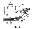
図3および4は、本発明の例示的な実施形態に従う、細長部材104の遠位端126の概略断面図を描写する。必要に応じて、図3および4に図示されるように、細長部材104は、ゲート部材137を含み得る。1つの実施形態において、ゲート部材137は、図3および4に図示されるように、細長部材104の遠位端126に配置される。あるいは、ゲート部材137は、細長部材104の長軸に沿ったいずれかの位置に配置され得る。
3 and 4 depict schematic cross-sectional views of the
1つの実施形態において、ゲート部材137は、拡張位置(図3に図示される)と退却位置(図4に図示される)との間を移動可能である。この拡張位置に配置される場合、ゲート部材137は、細長部材104の壁128の内側表面139から、細長部材104のルーメン130の中へ突出し、それによって縫合デバイス108が細長部材104の遠位端126に位置する開口部132の遠位方向に拡張されることを防ぐ。
In one embodiment, the
1つの実施形態において、細長部材104の遠位端126は、医師が、例えば、ゲート部材137に力を付与することによるか、またはゲート部材137を作動させることにより、ゲート部材137を上記拡張位置から動かすように行動しないかぎり、ゲート部材137は拡張位置を獲得するような設計である。例えば、細長部材104の遠位端126は、ゲート部材137上のあらゆる力の非存在またはゲート部材137の作動の非存在でその拡張位置にゲート部材137を配置するように設計された形状記憶材料から作製され得る。1つのこのような実施形態において、1本以上の作動弦127が、細長部材104の長さに沿って細長部材104の近位端124から細長部材104の遠位端126に向かって延びる。図3および4に図示されるように、1本以上の作動弦127が、細長部材104の壁128内に封入され、作動弦(単数または複数)127の各1本が、作動弦(単数または複数)127の遠位端129で、ゲート部材137の端部131に連結し得る。従って、ゲート部材137が拡張位置にある場合(図3)、ゲート部材137を退却位置(図4)に配置するために、医師は、作動弦127(単数または複数)を矢印141の方向に引いて、細長部材104のルーメン130から離れる方向にゲート部材137を回転させる。医師が作動弦(単数または複数)127を開放すると、細長部材104の遠位端126の形状記憶材料は、ゲート部材137を拡張位置に戻す。
In one embodiment, the
あるいは、別の実施形態において、ゲート部材137は、その拡張位置に配置されるための作動を必要とする。1つのこのような実施形態において、医師は、例えば、細長部材104の遠位端126で、壁128の全体または壁128の1つ以上の部分を細長部材104のルーメン130に向かって回転することにより、ゲート部材137を拡張位置に配置する。例えば、医師は、以下に示されるようなコントローラを採用して、拡張位置と退却位置との間でゲート部材137を回転させる。
Alternatively, in another embodiment, the
1つの実施形態において、図3に図示されるように、ゲート部材137は、拡張位置に配置されている場合、細長部材104の内側表面139の全周からかつその周囲に連続的に延びる。あるいは、ゲート部材137は、内側表面139の全周の単一の部分から延びるか、またはゲート部材137は、細長部材104の内側表面139の全周の異なる部分から間欠的に延び得る。
In one embodiment, as illustrated in FIG. 3, the
図4を参照して、ゲート部材137が退却位置に退却される場合、ゲート部材137は、もはや細長部材104のルーメン130の中に突出しない。従って、ゲート部材137が退却位置に配置されていると、縫合デバイス108は、細長部材104の遠位端126に位置している開口部132の遠位方向に拡張され得る。
With reference to FIG. 4, when the
1つの実施形態において、細長部材104および送達部材106は、例えば、ポリエチレン、ポリエーテルブロックアミドコポリマー(例えば、Philadelphia,PennsylvaniaのAtofina Chemicalsにより製造されるPEBAX(登録商標))、ポリウレタン、またはフッ素化ポリエチレンプロピレンのような生体適合性材料から製作される可撓性管である。別の実施形態において、細長部材104および/または送達部材106は、全体が金属(例えば、ステンレス鋼、Freemont,CaliforniaのNitinol Devices and Componentsにより製造されるニッケル−チタン合金であるNitinol)から作製される。さらに別の実施形態において、細長部材104および/または送達部材106は、金属製の先端を備えるポリマーシャフトを有する。
In one embodiment,
再び図2を参照して、いくつかの実施形態において第1のコントローラ112および第2のコントローラ114が、それぞれ細長部材104および送達部材106と通信することを可能にする例示的なインターフェース110が図示される。このような通信を可能とするために、細長部材104の近位端124および送達部材106の近位端136が、各々、インターフェース110に連結する。例示的な第1のコントローラ112および例示的な第2のコントローラ114は、例えば、それぞれ、細長部材104(細長部材104のゲート部材137を含む)および送達部材106を拡張し、退却し、またはそうでなければ操作し得る。
Referring again to FIG. 2, an
あるいは、単一のコントローラが、組織縫合システム100およびその中に配置される器具のすべての機能および操作を制御し得る。あるいは、複数のコントローラ(例えば、器具の遠位端を拡張し退却するための遠位端コントローラ、器具の一部分の角度をなす配向を変化させるための先端曲げコントローラ、および器具の構成要素を拡張しそして退却するための拡張コントローラ)が提供され得、当業者に公知のように、各1つが、組織縫合システム100の異なる構成要素または機能を制御し得る。例えば、別々のゲート部材コントローラが、細長部材104のゲート部材137を拡張し、退却し、またはそうでなければ操作するために提供され得る。さらに別の実施形態において、医師は、細長部材104、細長部材104のゲート部材137、および送達デバイス106を手動で、コントローラを何一つ使用することなく、拡張し、退却し、またはそうでなければ操作することにより、組織縫合システム100を操作する。
Alternatively, a single controller may control all functions and operations of the
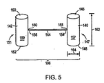
図5は、本発明の例示的な実施形態に従う連結された配置にある縫合デバイス108を描写する。図2および5を参照して、例示的な縫合デバイス108は、第一の組織係合部材140、第2の組織係合部材142、および第1の相互連結部材144を含む。1つの実施形態において、第1の組織係合部材140は、第1の端部146、反対の第2の端部148、およびこの第1の端部146と第2の端部148との間に配置される中間部分147を含む。同様に、第2の組織係合部材142は、第1の端部150、第1の端部150に対向する第2の端部152、および第1の端部150と第2の端部152との間に配置される中間部分151を含む。その一部分に対して、第1の相互連結部材144は、第1の組織係合部材140に連結される第1の固定端154および第2の組織係合部材142に連結される反対の、第2の固定端156を含む。
FIG. 5 depicts the
図6は、本発明の別の例示的な実施形態に従う組織縫合システム100を描写する。ここで、図5および6を参照して、1つの実施形態において、第1の組織係合部材140は、第1の組織係合部材140の第1の端部146から第2の端部148へ延びるルーメン157を含み、そして第2の組織係合部材142は、第2の組織係合部材142の第1の端部150から第2の端部152へ延びるルーメン159を含む。従って、1つの実施形態において、図6に描写されるように、細長部材104は、最初は、第2の組織係合部材142のルーメン159内にかつそれを貫いて、そして第1の組織係合部材140のルーメン157内にかつそれを貫いて配置され得る。
FIG. 6 depicts a
図6を参照して、1つの実施形態において、送達部材106は、送達部材106の近位端136から遠位端138へ延びるルーメン161を含む。従って、細長部材104はまた、最初は、送達部材106のルーメン161内にかつそれを貫いて配置され得る。別の実施形態において、送達部材106、第1の組織係合部材140、および第2の組織係合部材142は、細長部材104の壁128の外側表面163にわたって滑動可能に移動される。送達部材106を細長部材104の遠位端126に向かって拡張すると、縫合デバイス108は、細長部材104の遠位端126に向かって、細長部材104の遠位端126の遠位方向に拡張される。さらに、別の実施形態では、第1の組織係合部材140の1つまたは両方の端部146、148、ならびに/または第2の組織係合部材142の1つまたは両方の端部150、152は、丸められているか、テーパー状であるか、または面取りされてあり、患者の組織を通る第1の組織係合部材140および/または第2の組織係合部材142の通過を容易にする。
With reference to FIG. 6, in one embodiment,
再び、図5を参照して、1つの実施形態において、示されるように、第1の相互連結部材144の第1の固定端154は、第1の組織係合部材140の対向する端部146、148のうちの1つにおいてよりはむしろ、第1の組織係合部材140の第1の端部146と第2の端部148との間に位置するある点で第1の組織係合部材140に連結される。従って、このような実施形態において、第1の相互連結部材144の第1の固定端154は、第1の組織係合部材140の中間部分147に連結され、そして第1の組織係合部材140の対向する端部146、148は、両方とも自由端である。あるいは、別の実施形態において、第1の相互連結部材144の第1の固定端154は、第1の組織係合部材140に、第1の組織係合部材140の第1の端部146または第2の端部148のいずれかで連結される。従って、このような実施形態において、第1の組織係合部材140の第1の端部146および第2の端部148のうちの1つは、固定端である。類似の様式で、第1の相互連結部材144の第2の固定端156は、第2の組織係合部材142に、第2の組織係合部材142の第1の端部150と第2の端部152との間に位置するある点で第2の組織係合部材142に連結され得る(すなわち、第1の相互連結部材144は、第2の組織係合部材142の中間部分151に連結され得る)か、あるいは、第2の組織係合部材142の対向する端部150、152のうちの1つにおいて第2の組織係合部材142に連結され得る。
Referring again to FIG. 5, in one embodiment, as shown, the first
1つの実施形態において、第1の相互連結部材144は、その第1の固定端154で第1の組織係合部材140に、そしてその第2の固定端156で第2の組織係合部材142に、例えば、接着剤(例えば、膠)により連結される。あるいは、第1の相互連結部材144は、その第1の固定端154に第1のヒンジ158を、その第2の固定端156に第2のヒンジ160を含む。1つのこのような実施形態において、第1のヒンジ158は、第1の相互連結部材144を第1の組織係合部材140に連結し、そして第2のヒンジは、第1の相互連結部材144を第2の組織係合部材142に連結する。1つの実施形態において、第1のヒンジ158および第2のヒンジ160は、それぞれ第1の組織係合部材140および第2の組織係合部材142の、互いに対する、および第1の相互連結部材144に対する回転運動を可能にする。
In one embodiment, the first interconnecting
1つの実施形態において、縫合デバイス108は、予め組立られており(例えば、製造されており)、その結果、第1の相互連結部材144は、第1の組織係合部材140を第2の組織係合部材142に連続的に連結する。換言すれば、医師は、その医師の縫合システム100の使用の間のどの地点においても、第1の相互連結部材144の一部を第1の相互連結部材144の別の部分に連結する必要も、または2つの組織係合部材140、142のうちのいずれか1つを第1の相互連結部材144に連結する必要もない。むしろ、縫合デバイス108は、例えば、図5に示され、そして例えば図5を参照して記載されるように、その連結した配置で患者の中に挿入可能である。
In one embodiment, the
1つの実施形態において、第1の相互連結部材144は、可撓性であるが弾性のある材料から作製され、第1の相互連結部材144が、図2および6に図示されるような変形位置(例えば、曲げ位置)と応力を受けていない位置(例えば、図5に示される真直ぐな配置)との間で交替することを可能にする。1つの実施形態において、第1の相互連結部材144は、上記変形位置と応力を受けていない位置との間で、それぞれ、力の付与および除去を通して、交替する。図5を参照して、第1の相互連結部材144の応力を受けていない位置において、第1の組織係合部材140の長手方向軸および第2の組織係合部材142の長手方向軸は、1つの実施形態においては、各々、実質的に第1の相互連結部材144の長手方向軸に直交している。図2および6を参照して、第1の相互連結部材144の変形位置において、第1の組織係合部材140の長手方向軸および第2の組織係合部材142の長手方向軸は、1つの実施形態においては、各々、実質的に第1の相互連結部材144の長手方向軸と平行である。
In one embodiment, the first interconnecting
図2を参照して、操作において、1つの実施形態においては、縫合デバイス108は、最初は、その第1の相互連結部材144を変形位置にして、細長部材104のルーメン130内に配置される。さらに、1つの実施形態において、細長部材104の壁128は、縫合デバイス108が、細長部材104のルーメン130内に位置される間、縫合デバイスの第1の相互連結部材144を変形位置に拘束する。一旦、縫合デバイス108が、遠位方向に進められ、細長部材104の遠位端126にある開口部132を通って出ると、第1の相互連結部材144の弾性によって、1つの実施形態においては、縫合デバイス108の第1の相互連結部材144が、図5に図示される、その応力を受けていない位置を回復する。
With reference to FIG. 2, in operation, in one embodiment, the
第1の相互連結部材144がそれから製造され得る例示的な弾性材料としては、排他的にではなく、ポリ乳酸(PLA)、ポリエチレングリコール(PEG)、ポリカプロラクトン(PCL)、ポリグリコール酸(PGA)、もしくはマグネシウムのような生物吸収可能な材料、非再吸収性の材料(例えば、排他的にではなく、金属(例えば、ニチノール)もしくはポリマー(例えば、ウレタン))および/またはゴムが挙げられる。
Exemplary elastic materials from which the first interconnecting
本発明のいくつかの実施形態において、縫合デバイス108の第1の相互連結部材144は、弾性的な特性を有する。例えば、1つの実施形態において、第1の相互連結部材144は、伸張され得、そしてその後、伸張力が取り除かれると、元の状態に戻され得る。より具体的には、1つの実施形態において、第1の相互連結部材144が伸張され、第1の組織係合部材140を第2の組織係合部材142から離して動かすとき、回復力が、第1の相互連結部材144において生成される。この回復力は、伸張力が取り除かれたとき、第1の組織係合部材140を第2の組織係合部材142に向かって引き戻すように作用する。第1の相互連結部材144がそれから製造され得る例示的な弾性材料としては、排他的にではなく、ポリ乳酸(PLA)、ポリエチレングリコール(PEG)、ポリカプロラクトン(PCL)、もしくはポリグリコール酸(PGA)のような生物吸収可能な材料、非再吸収性の材料(例えば、排他的にではなく、ポリマーもしくはポリマーブレンド(例えば、ウレタン))および/またはゴムが挙げられる。
In some embodiments of the invention, the first interconnecting
ここで図5を参照して、1つの実施形態において、第1の組織係合部材140および/または第2の組織係合部材142は、実質的に円筒状である。あるいは、第1の組織係合部材140および第2の組織係合部材142は、他の形状(例えば、直角プリズム)を有し得る。別の実施形態において、第1の組織係合部材140および第2の組織係合部材142のうちの一方または両方は、非外傷性構造を有する、すなわち患者の組織に対して損傷または外傷をもたらし得る外側方向の突起または突出物がまったくない。それ故に、患者の組織を第1の組織係合部材140および第2の組織係合部材142に直接かつ密接に接触させることに対する障害はない。例えば、組織係合部材140,142が非外傷性である1つの実施形態において、第1の組織係合部材140の対向する端部146、148のうちの一方または両方ならびに/あるいは第2の組織係合部材142の対向する端部150、152のうちの一方または両方は、丸められている。
Referring now to FIG. 5, in one embodiment, the first
1つの実施形態において、第1の相互連結部材144は、約1.0mmと約20.0mmとの間の長さおよび約0.01mmと約2.0mmとの間の断面直径を有する。別の実施形態において、組織係合部材、例えば、第1の組織係合部材140は、約1.0mm〜約20.0mmの間の長さ162および約0.05mm〜約5.0mmの断面直径164を有する。
In one embodiment, the first interconnecting
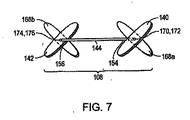
図7は、本発明の別の例示的な実施形態に従う縫合デバイス108を描写する。この例示的な実施形態によれば、縫合デバイス108はまた、1つ以上の第3の組織係合部材168を含む。例えば、縫合デバイス108は、2つの第3の組織係合部材168a、168bを備え、それらのうちの1つが第1の相互連結部材144の第1の固定端154に連結され、それらのうちの別の1つが第1の相互連結部材144の第2の固定端156に連結される。1つの実施形態において、第1の組織係合部材140の長手方向軸に沿った中間点170が、第3の組織係合部材168aの長手方向軸に沿った中間点172に連結される。1つの実施形態において、第1の組織係合部材140およびその第3の組織係合部材168aは、細長部材104のルーメン130を通して、同軸で送達される。細長部材104の遠位端126で開口部132を出る際に、第1の組織係合部材140およびその第3の組織係合部材168aは、例えば、互いに対して回転し、その結果、1つの実施形態において、第1の組織係合部材140の長手方向軸が、その第3の組織係合部材168aの長手方向軸に実質的に直交して配向され、それにより十字またはX形状を形成する。同様に、第2の組織係合部材142の長手方向軸に沿った中間点174は、別の第3の組織係合部材168bの長手方向軸に沿った中間点176に連結され得る。1つの実施形態において、第2の組織係合部材142およびその第3の組織係合部材168bは、細長部材104のルーメン130を通して、同軸で送達される。細長部材104の遠位端126で開口部132を出る際に、第2の組織係合部材142およびその第3の組織係合部材168bは、例えば、互いに対して回転し、その結果、1つの実施形態において、第2の組織係合部材142の長手方向軸が、その第3の組織係合部材168bの長手方向軸に実質的に直交して配向され、それにより十字またはX形状を形成する。あるいは、他の実施形態において、縫合デバイス108が、細長部材104の遠位端126で開口部132を出るとき、第1の組織係合部材140の長手方向軸および第2の組織係合部材142の長手方向軸は、それらのそれぞれの第3の組織係合部材168a、168bの長手方向軸に対して、0°と180°との間の角度で、各々、配向される。
FIG. 7 depicts a
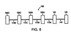
図8は、本発明のさらに別の実施形態に従う縫合デバイス108を描写する。この例示的な実施形態によれば、縫合デバイス108は、1つ以上の第2の相互連結部材178をさらに含む。例えば、1つの実施形態において、縫合デバイス108は、第2の相互連結部材178の鎖を含む。1つのこのような実施形態において、第2の相互連結部材178の少なくとも1つが、第1の組織係合部材140または第2の組織係合部材142のいずれかに連結される。例えば、図8に図示されるように、第2の相互連結部材178Aは、第2の組織係合部材142に連結される。さらに、その鎖の中の第2の相互連結部材178の各1つは、隣接する第2の相互連結部材178から、第3の組織係合部材168により分離され得る。例えば、図8に図示されるように、第2の相互連結部材178Aは、隣接する第2の相互連結部材178Bから、第3の組織係合部材168Aにより分離される。従って、本発明の縫合デバイス108は、一連の交互する組織係合部材と相互連結部材とからなり得る。任意の数の交互する組織係合部材および相互連結部材が、直列に連結され、鎖を形成し得る。さらに、一般に、第2の相互連結部材178は、上に記載された第1の相互連結部材144の特性(例えば、第1の相互連結部材144の弾性を含む)のいくらかまたはすべてを含み得る。従って、第2の相互連結部材178はまた、変形位置と応力を受けていない位置との間を交替し得る。
FIG. 8 depicts a
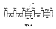
図9は、本発明のさらに別の例示的な実施形態に従う縫合デバイス108を描写する。この例示的な実施形態によれば、2つ以上の相互連結部材が隣接する組織係合部材を連結し得る。例えば、第1の相互連結部材144および第2の相互連結部材178Eの両方が、第1の組織係合部材140を第2の組織係合部材142に連結し得る。同様に、別の例として、3つの第2の相互連結部材178B、178F、178Gが、2つの隣接する第3の組織係合部材168A、168Bを連結し得る。
FIG. 9 depicts a
図10は、本発明の別の例示的な実施形態に従う縫合デバイス108’を描写する。この例示的な縫合デバイス108’は、上に記載されたのと同様に、第1の相互連結部材144’、第1の組織係合部材140’、および第2の組織係合部材142’を含む。1つの実施形態において、縫合デバイス108’は、第1の相互連結部材144’に連結される締付け機構180をさらに含む。第1の相互連結部材144’は、例えば、糸であり得る。患者の組織中での縫合デバイス108’の移植の後に、締付け機構180は、第1の組織係合部材140’と第2の組織係合部材142’との間の第1の相互連結部材中のあそびを取り除くために使用され得る。1つの実施形態において、例えば、締付け機構180は、ラチェットであり得る。あるいは、他の実施形態において、締付け機構180は、ワイヤー連結、引き結び、ねじ機構である。
FIG. 10 depicts a suturing device 108 'according to another exemplary embodiment of the present invention. This exemplary suturing device 108 'includes a first interconnecting
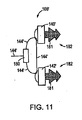
1つの実施形態において、依然として図10を参照して、第1の組織係合部材140’および/または第2の組織係合部材142’は、例えば螺旋状組織アンカー179のようなアンカー182を含む。従って、第1の組織係合部材140’および/または第2の組織係合部材142’は、患者の組織中にねじ込まれ得る。あるいは、別の実施形態において、第1の組織係合部材140’および/または第2の組織係合部材142’は、組織係合部材140’、142’を患者の組織中に移植するための異なる形状のアンカー182を含む。例えば、第1の組織係合部材140’および/または第2の組織係合部材142’は、図11に示されるような、かかりのある組織アンカー181を含み得る。従って、第1の組織係合部材140’および/または第2の組織係合部材142’のかかりのある組織アンカー181は、患者の組織の中へ押され、係合部材140’、142’を患者の組織中に固定し得る。
In one embodiment, still referring to FIG. 10, the first
組織係合部材140、140’、142、142’、168、相互連結部材144、144’、178、および締付け機構180のうちのいくつかまたはそれらのすべては、例えば、ポリ乳酸(PLA)、ポリエチレングリコール(PEG)、ポリカプロラクトン(PCL)、ポリグリコール酸(PGA)、またはマグネシウムのような、患者の体への配置の後に、経時的に生物分解し、患者の体の中に吸収される生物吸収可能な材料から製造され得る。他の実施形態において、組織係合部材140、140’、142、142’、168、相互連結部材144、144’、178、および締付け機構180のうちのいくつかまたはそれらのすべては、縫合デバイス108、108’が患者の組織内に移植される場合に、組織の内殖を可能にする生物学的材料(例えば、細胞外マトリクス材料)から製造され得る。さらに別の実施形態において、組織係合部材140、140’、142、142’、168、相互連結部材144、144’、178、および締付け機構180のうちのいくつかまたはそれらのすべては、組織増殖を刺激するための材料(例えば、反応性材料)でコーティングされ、そして/または含浸される。1つの実施形態において、その増殖刺激材料は、コラーゲンである。別の実施形態において、その増殖刺激材料は、血管内皮増殖因子、塩基性線維芽細胞増殖因子、または血管新生増殖因子のような増殖因子である。さらに別の実施形態において、この増殖刺激材料は、例えば、細胞または遺伝子のような、組織増殖を刺激するための薬理学的因子である。あるいは、さらに別の実施形態において、この増殖刺激材料は、例えば、綿実油またはアルコールのような、炎症性応答を助長するための刺激原である。
Some or all of the
あるいは、生物吸収可能でない材料は、縫合デバイス108、108’の異なる部分を製造するために使用され得る。組織係合部材140、140’、142、142’、168および/または締付け機構180は、例えば、ポリマー材料(例えば、ポリエチレン、ナイロン、ポリプロピレン、ポリエステル、またはポリウレタン)、形状記憶材料、または金属を使用して製造され得る。それらの部分に対して、相互連結部材144、144’、178は、例えば、ポリマー材料(例えば、ポリエチレンまたはポリウレタン)、形状記憶材料、金属、糸、ばね、または他のエラストマーを使用して製造され得る。例えば、組織係合部材140、140’、142、142’、168、および相互連結部材144、144’、178は、Nitinolのようなニッケル−チタン合金を使用して製造され得る。別の例として、組織係合部材140、140’、142、142’、168、および相互連結部材144、144’、178は、例えば、ポリマーのような単一片の材料からそれらを成形またはスタンピングすることにより、一体型ユニットとして製造され得る。
Alternatively, materials that are not bioabsorbable can be used to manufacture different portions of the
さらに別の実施形態において、組織係合部材140、140’、142、142’、168、相互連結部材144、144’、178、および締付け機構180のうちのいくつかまたはそれらのすべては、例えば、ヘパリンのような、血栓症を低減する材料でコーティングされる。さらに別の実施形態において、組織係合部材140、140’、142、142’、168、相互連結部材144、144’、178、および締付け機構180のうちのいくつかまたはそれらのすべては、放射線不透過性材料を含む。
In yet another embodiment, some or all of
別の局面において、本発明は、組織を縫合する方法を提供する。図12A〜12Dは、本発明に従う、患者の心臓における心房内中隔中の開存卵円孔52を経皮的に縫合して閉じるための方法の1つの実施形態を図示する。最初に図12Aを参照して、医師は、組織縫合システムの遠位端183(例えば、図2の組織縫合システム100)を二次中隔62の近接して、患者の右心房56内に配置する。
In another aspect, the present invention provides a method for suturing tissue. 12A-12D illustrate one embodiment of a method for percutaneously suturing and closing the
必要に応じて、図12Aに示されるように、医師はまた、組織安定化デバイス184を組織縫合システム100とともに採用する。1つのこのような実施形態において、組織安定化デバイス184は、カテーテル185に連結される。カテーテル185は、近位端(示さず)、遠位端187、この近位端からこの遠位端187に延びるルーメン189、およびカテーテル185の遠位端187に配置され、かつカテーテル185のルーメン189と流体連絡している開口部191を含む。1つの実施形態において、図示されるように、カテーテル185は、シース102のルーメン120内に配置される。細長部材104、送達部材106、および縫合デバイス108は、カテーテル185のルーメン189内に配置される。
If desired, the physician also employs a
1つの実施形態において、医師は、組織安定化デバイス184を患者の心臓の二次中隔62と一次中隔60との間で開存卵円孔52内にかつそれを通して配置する。この組織安定化デバイス184は、医師により、例えば、以下に説明されるように、細長部材104の切断部材134を用いて、二次中隔62および一次中隔60を貫通して穴を形成する前に、二次中隔62および一次中隔60の動きを制限するために使用される。組織安定化デバイス184はまた、カテーテル185の遠位端187を二次中隔62および一次中隔60が重なる領域に配置するのに供される。従って、細長部材104が、拡張されてカテーテル185の遠位端187で開口部191を通って出るとき、細長部材104の切断部材134は、二次中隔62および一次中隔60が重なる領域においてそれらを貫通して穴を穿孔する。以下にさらに説明される方法に従って、縫合デバイス108は、それによって中隔60、62を通って、それらが重なる領域に配置される。
In one embodiment, the physician places a
患者における心臓組織を安定化するために、および二次中隔62および一次中隔60が重なる領域において上に記載された要素を配置するために適した例示的な組織安定化デバイスおよび可撓性部材としては、米国特許出願第10/660,444号に記載されるものが挙げられ、その開示は、これによりその全体が本明細書中に参考として援用される。例えば、組織安定化デバイス184は、i)図12Aに図示される、螺旋形状を有する可撓性コイルであり得るか;ii)一般に、平面状アレイを形成する3つの可撓性六角形部材を含み得るか;iii)2つの可撓性部材を含み得、それらの各1つが、ルーメンから出る際に1回以上関節運動するように予め形作られた脚(例えば、ワイヤ)を含むか;iv)2つの可撓性部材を含み、それらの各1つがループ部分を含むか;またはv)閉鎖ループを形成する単独の可撓性部材であり得る。
Exemplary tissue stabilization device and flexibility suitable for stabilizing cardiac tissue in a patient and for placing the elements described above in the region where the
あるいは、別の実施形態において、医師は、開存卵円孔52を縫合することにおいて、組織安定化デバイス184を採用しない。従って、図12B〜12Dは、図面を単純化および明瞭化するために組織安定化デバイス184を図示していないが、組織安定化デバイスが、実際は、存在してもしなくてもよいことが理解される。
Alternatively, in another embodiment, the physician does not employ the
ここで図12Bを参照して、医師は、1つの実施形態において、細長部材104を遠位方向に拡張し、その結果、細長部材104の切断部材134が、二次中隔62の組織表面186に、二次中隔62が一次中隔60に重なるある地点で接触する。細長部材104を進め続けることにより、医師は、第1の穴188を二次中隔62に形成し、そして引き続いて第2の穴190を重なる一次中隔60に形成する。
Referring now to FIG. 12B, in one embodiment, the physician expands the
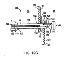
ここで、細長部材104の遠位端126が左心房58中にある、図12Cを参照して、送達部材106は、細長部材104の遠位端126に向かって、第1の組織係合部材140が細長部材104の遠位端126で開口部132を出るまで、進められる。ひとたび第1の組織係合部材140が開口部132を出ると、第1の相互連結部材144の弾性が、第1の相互連結部材144の第1の固定端154を、応力を受けていない(例えば、真直ぐな)位置に戻らせ、その結果、第1の組織係合部材140の長手方向軸は、第1の相互連結部材144の長手方向軸と実質的に直交する。
Referring now to FIG. 12C, where the
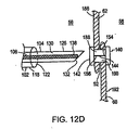
図12Dを参照して、医師は、次いで、第2の穴190および第1の穴188を通して、細長部材104を近位方向に退却させて戻し、その結果、第1の組織係合部材140は、一次中隔60の表面192に隣接して位置される。医師は、細長部材104の遠位端126が、右心房56の中に配置されるまで、細長部材104を退却し続ける。送達部材106は、第2の組織係合部材142が、細長部材104の遠位端126の開口部132を出るまで、その後さらに遠位方向に進められる。ひとたび、第2の組織係合部材142が開口部132を出ると、第1の相互連結部材144の弾性は、第1の相互連結部材144の第2の固定端156を応力を受けていない(例えば、真直ぐな)位置に戻させ、その結果、第2の組織係合部材142の長手方向軸は、第1の相互連結部材144の長手方向軸と実質的に直交する。第2の組織係合部材142は、それにより二次中隔62の組織表面186に隣接して配置される。そのように配置されると、縫合デバイス108は、一次中隔60および二次中隔62を、第1の組織係合部材140と第2の組織係合部材142との間に保持する。
Referring to FIG. 12D, the physician then retracts the
図13は、本発明の別の実施形態に従って、患者の心臓中の心房内中隔に移植された縫合デバイス108を描写する。この例示的な実施形態によれば、上に記載されたように、二次中隔62および一次中隔60が重なる地点で第1の穴188を二次中隔62を通して、第2の穴190を一次中隔60を通して作成するよりはむしろ、医師は、穴188、190を二次中隔62および一次中隔60が重ならない地点に作成する。例えば、医師は、切断部材134を使用して、第1の穴188を二次中隔62を通して作成し、第1の組織係合部材140を、二次中隔62の組織表面に隣接して左心房58中に配置し、細長部材104を右心房56中へ近位方向に引き込み戻し、切断部材134を使用して一次中隔60を通して穴190を作成し、第2の組織係合部材142を一次中隔60の組織表面に隣接して左心房58中に配置し、そして最後に患者の体から取り除くために細長部材104を右心房56中へ近位方向に引き込み戻す。縫合デバイス108は、従って、一次中隔60および二次中隔62を、図13に図示されるように、開存卵円孔52のトンネルの中の位置を占めることなく捕まえる。あるいは、別の実施形態において、医師は、反対の順序で、穴188、190を二次中隔62および一次中隔60中に作成する。
FIG. 13 depicts a
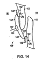
図14は、本発明の別の実施形態に従って、患者の心臓中の心房内中隔に移植された縫合デバイス108’を描写する。この例示的な実施形態によれば、左心房58に接近するために穴188、190を二次中隔62および一次中隔60を通して形成するよりはむしろ、医師は、組織係合部材140’、142’の螺旋状組織アンカー179(またはかかりのある組織アンカー181)を一次中隔60および二次中隔62の右心房壁の中へ進める。1つのこのような実施形態において、細長部材104の遠位端126は、それらが送達部材106により細長部材104の遠位端126へ進められるにつれて、組織係合部材140’、142’に係合するように適合される。ひとたび組織係合部材140’、142’が細長部材104の遠位端126に係合されると、医師は、次いで、細長部材104を回転し、組織係合部材140’、142’の螺旋状組織アンカー179を患者の組織にねじ込むか、または、あるいは医師は、細長部材104を進めて組織係合部材140’、142’のかかりのある組織アンカー181を患者の組織中に押す。従って、縫合デバイス108’は、図14に図示されるように、一次中隔60および二次中隔62を捕まえる。必要に応じて、医師は、次いで締付け機構180を使用して、第1の相互連結部材144’中の第1の組織係合部材140’と第2の組織係合部材142’との間の任意のあそびを取り除き得る。
FIG. 14 depicts a suturing device 108 'implanted in an intra-atrial septum in a patient's heart according to another embodiment of the present invention. According to this exemplary embodiment, rather than forming
他の実施形態において、一連の交互する組織係合部材と相互連結部材とを含む縫合デバイス108、108’を送達するために、図8および9に図示されるように、医師は、図12A〜12D、図13、または図14のいずれかを参照して上に記載された工程を繰り返す。いくつかのこのような実施形態において、縫合デバイス108、108’を、細長部材104のルーメン130を通して遠位方向に進めるために、送達部材106は、この一連の交互する組織係合部材および相互連結部材における最も遠位の組織係合部材(例えば、図8および9における第3の組織係合部材168D)に隣接する。
In other embodiments, to deliver a
上に記載された方法における工程の順序および/または特定の行動を実行するための順序は、本発明が作動可能である限り、重要でないことが理解されるべきである。さらに、2つ以上の工程または行動が同時に行われ得る。 It should be understood that the order of steps and / or order for performing certain actions in the methods described above is not critical as long as the invention is operable. In addition, two or more steps or actions can be performed simultaneously.
本発明の特定の実施形態が上に記載された。しかし、本発明はこれらの実施形態に限定されず、むしろ意図は、本明細書中に明示的に記載されたものに対する付加物および改変はまた、本発明の範囲内に含まれることであることが明示的に注記される。さらに、本明細書中に記載された種々の実施形態の特徴は相互に排他的ではなく、たとえ種々の組合せおよび並べ替えが、本明細書中に明示的になされていなくとも、本発明の趣旨および範囲を逸脱することなく、このような組合せおよび並べ替えにおいて存在し得ることが理解されるべきである。実際、本明細書中に記載されたもののバリエーション、改変、および他の実施は、本発明の趣旨および範囲を逸脱することなく、当業者に思い浮かぶ。従って、本発明は、前出の例示的な記載によってのみ規定されるべきではない。 Specific embodiments of the invention have been described above. However, the invention is not limited to these embodiments, but rather the intent is that additions and modifications to those explicitly described herein are also included within the scope of the invention. Are explicitly noted. Further, the features of the various embodiments described herein are not mutually exclusive, and the spirit of the present invention is intended even if various combinations and permutations are not explicitly made in the specification. It should be understood that such combinations and permutations may exist without departing from the scope and scope. Indeed, variations, modifications and other implementations of what is described herein will occur to those skilled in the art without departing from the spirit and scope of the invention. Accordingly, the present invention should not be defined only by the preceding illustrative description.
Claims (28)
縫合デバイスであって、以下:
第1の組織係合部材であって、第1の端部、第2の端部および該第1の端部と該第2端部との間に配置される第1の中間部分を備える、第1の組織係合部材;
第2の組織係合部材であって、第3の端部、第4の端部および該第3の端部と該第4端部との間に配置される第2の中間部分を備える、第2の組織係合部材;ならびに
第1の相互連結部材であって、該第1の組織係合部材の第1の中間部分に連結される第1の固定端および該第2の組織係合部材に連結される第2の固定端を備える、第1の相互連結部材、
を備え、ここで該縫合デバイスが、連結された配置で患者に挿入可能である、縫合デバイス、
を含む、縫合システム。 A suturing system comprising:
A suturing device comprising:
A first tissue engaging member comprising a first end, a second end, and a first intermediate portion disposed between the first end and the second end; A first tissue engaging member;
A second tissue engaging member comprising a third end, a fourth end and a second intermediate portion disposed between the third end and the fourth end. A second tissue engaging member; and a first interconnecting member, the first fixed end coupled to the first intermediate portion of the first tissue engaging member and the second tissue engaging A first interconnecting member comprising a second fixed end coupled to the member;
A suturing device, wherein the suturing device is insertable into a patient in a coupled arrangement,
A suturing system.
細長部材であって、該細長部材は、近位端、遠位端、該近位端から該遠位端へ延びる壁、および該遠位端に配置される切断部材を備え、該壁は、該細長部材の近位端から該細長部材の遠位端へ延びるルーメンを規定し、そして該壁は、該細長部材の遠位端で開口部を規定する、細長部材、
を備え、ここで前記縫合デバイスが、該細長部材の該ルーメン内に配置される、請求項1に記載の縫合システム。 further,
An elongate member comprising a proximal end, a distal end, a wall extending from the proximal end to the distal end, and a cutting member disposed at the distal end, the wall comprising: An elongate member defining a lumen extending from a proximal end of the elongate member to a distal end of the elongate member, and the wall defining an opening at the distal end of the elongate member;
The suturing system of claim 1, wherein the suturing device is disposed within the lumen of the elongate member.
細長部材であって、該細長部材は、近位端、遠位端、該近位端から該遠位端へ延びる壁、および該遠位端に配置される切断部材を備える、細長部材、
を備え、ここで該細長部材は、前記第1の組織係合部材の第1のルーメン内でかつ前記第2の組織係合部材の第2のルーメン内に配置される、請求項10に記載の縫合システム。 further,
An elongate member, the elongate member comprising a proximal end, a distal end, a wall extending from the proximal end to the distal end, and a cutting member disposed at the distal end;
11. The elongate member, wherein the elongate member is disposed within a first lumen of the first tissue engaging member and within a second lumen of the second tissue engaging member. Suture system.
第1の組織係合部材;
第2の組織係合部材;
第1の相互連結部材であって、該第1の組織係合部材を該第2の組織係合部材に連結する、第1の相互連結部材;および
該第1の組織係合部材に連結される第1のアンカー、
を備える、縫合デバイス。 A suturing device comprising:
A first tissue engaging member;
A second tissue engaging member;
A first interconnecting member, the first interconnecting member connecting the first tissue engaging member to the second tissue engaging member; and coupled to the first tissue engaging member A first anchor,
A suturing device comprising:
縫合デバイスを患者の心臓の中へ挿入する工程であって、該縫合デバイスは、以下:
第1の組織係合部材であって、第1の端部、第2の端部および該第1の端部と該第2端部との間に配置される第1の中間部分を備える、第1の組織係合部材;
第2の組織係合部材であって、第3の端部、第4の端部および該第3の端部と該第4端部との間に配置される第2の中間部分を備える、第2の組織係合部材;ならびに
第1の相互連結部材であって、該第1の組織係合部材の第1の中間部分に連結される第1の固定端および該第2の組織係合部材に連結される第2の固定端を備える、第1の相互連結部材、
を備え、ここで該縫合デバイスが、連結された配置で患者に挿入可能である、工程;ならびに
該縫合デバイスを該患者の心臓中の少なくとも1つの組織表面に取付ける工程、
を包含する、方法。 A method for suturing tissue, comprising:
Inserting a suturing device into a patient's heart, the suturing device comprising:
A first tissue engaging member comprising a first end, a second end, and a first intermediate portion disposed between the first end and the second end; A first tissue engaging member;
A second tissue engaging member comprising a third end, a fourth end and a second intermediate portion disposed between the third end and the fourth end. A second tissue engaging member; and a first interconnecting member, the first fixed end coupled to the first intermediate portion of the first tissue engaging member and the second tissue engaging A first interconnecting member comprising a second fixed end coupled to the member;
And wherein the suturing device is insertable into a patient in a coupled arrangement; and attaching the suturing device to at least one tissue surface in the patient's heart;
Including the method.
前記第1の組織係合部材を、第1の組織層中の第1の穴および第2の組織層中の第2の穴を通って拡張する工程;
該第1の組織係合部材を該第2の組織層の組織表面に配置する工程;および
該第2の組織係合部材を該第1の組織層の組織表面に配置する工程、
を包含する、請求項24に記載の組織を縫合するための方法。 Attaching the suturing device comprises:
Expanding the first tissue engaging member through a first hole in a first tissue layer and a second hole in a second tissue layer;
Disposing the first tissue engaging member on the tissue surface of the second tissue layer; and disposing the second tissue engaging member on the tissue surface of the first tissue layer;
25. A method for suturing tissue according to claim 24, comprising:
前記第1の組織係合部材を、第1の組織層中の第1の穴を通って拡張する工程;
該第1の組織係合部材を該第1の組織層の組織表面に配置する工程;
前記第2の組織係合部材を、第2の組織層中の第2の穴を通って拡張する工程;および
該第2の組織係合部材を該第2の組織層の組織表面に配置する工程、
を包含する、請求項24に記載の組織を縫合するための方法。 Attaching the suturing device comprises:
Expanding the first tissue engaging member through a first hole in a first tissue layer;
Disposing the first tissue engaging member on a tissue surface of the first tissue layer;
Expanding the second tissue engaging member through a second hole in the second tissue layer; and disposing the second tissue engaging member on a tissue surface of the second tissue layer. Process,
25. A method for suturing tissue according to claim 24, comprising:
Applications Claiming Priority (2)
| Application Number | Priority Date | Filing Date | Title |
|---|---|---|---|
| US50194803P | 2003-09-11 | 2003-09-11 | |
| PCT/US2004/012913 WO2005034763A1 (en) | 2003-09-11 | 2004-04-27 | Devices, systems, and methods for suturing tissue |
Publications (2)
| Publication Number | Publication Date |
|---|---|
| JP2007504885A true JP2007504885A (en) | 2007-03-08 |
| JP2007504885A5 JP2007504885A5 (en) | 2007-05-31 |
Family
ID=34434834
Family Applications (1)
| Application Number | Title | Priority Date | Filing Date |
|---|---|---|---|
| JP2006526055A Pending JP2007504885A (en) | 2003-09-11 | 2004-04-27 | Devices, systems and methods for suturing tissue |
Country Status (5)
| Country | Link |
|---|---|
| US (1) | US7691112B2 (en) |
| EP (1) | EP1663011A1 (en) |
| JP (1) | JP2007504885A (en) |
| CA (1) | CA2538476A1 (en) |
| WO (1) | WO2005034763A1 (en) |
Cited By (1)
| Publication number | Priority date | Publication date | Assignee | Title |
|---|---|---|---|---|
| JP2008541952A (en) * | 2005-06-02 | 2008-11-27 | コーディス・コーポレイション | Device for closing the patent foramen ovale |
Families Citing this family (154)
| Publication number | Priority date | Publication date | Assignee | Title |
|---|---|---|---|---|
| US8795332B2 (en) | 2002-09-30 | 2014-08-05 | Ethicon, Inc. | Barbed sutures |
| US6241747B1 (en) | 1993-05-03 | 2001-06-05 | Quill Medical, Inc. | Barbed Bodily tissue connector |
| US5931855A (en) | 1997-05-21 | 1999-08-03 | Frank Hoffman | Surgical methods using one-way suture |
| US7662161B2 (en) | 1999-09-13 | 2010-02-16 | Rex Medical, L.P | Vascular hole closure device |
| US6440152B1 (en) * | 2000-07-28 | 2002-08-27 | Microvena Corporation | Defect occluder release assembly and method |
| US7056331B2 (en) | 2001-06-29 | 2006-06-06 | Quill Medical, Inc. | Suture method |
| US7288105B2 (en) * | 2001-08-01 | 2007-10-30 | Ev3 Endovascular, Inc. | Tissue opening occluder |
| US6848152B2 (en) | 2001-08-31 | 2005-02-01 | Quill Medical, Inc. | Method of forming barbs on a suture and apparatus for performing same |
| US20060052821A1 (en) * | 2001-09-06 | 2006-03-09 | Ovalis, Inc. | Systems and methods for treating septal defects |
| US20050267495A1 (en) * | 2004-05-17 | 2005-12-01 | Gateway Medical, Inc. | Systems and methods for closing internal tissue defects |
| US6776784B2 (en) * | 2001-09-06 | 2004-08-17 | Core Medical, Inc. | Clip apparatus for closing septal defects and methods of use |
| US6702835B2 (en) | 2001-09-07 | 2004-03-09 | Core Medical, Inc. | Needle apparatus for closing septal defects and methods for using such apparatus |
| US20090054912A1 (en) * | 2001-09-06 | 2009-02-26 | Heanue Taylor A | Systems and Methods for Treating Septal Defects |
| US20080015633A1 (en) * | 2001-09-06 | 2008-01-17 | Ryan Abbott | Systems and Methods for Treating Septal Defects |
| US6773450B2 (en) | 2002-08-09 | 2004-08-10 | Quill Medical, Inc. | Suture anchor and method |
| WO2004026147A2 (en) * | 2002-09-23 | 2004-04-01 | Nmt Medical, Inc. | Septal puncture device |
| US8100940B2 (en) | 2002-09-30 | 2012-01-24 | Quill Medical, Inc. | Barb configurations for barbed sutures |
| US20040088003A1 (en) * | 2002-09-30 | 2004-05-06 | Leung Jeffrey C. | Barbed suture in combination with surgical needle |
| US7780700B2 (en) * | 2003-02-04 | 2010-08-24 | ev3 Endovascular, Inc | Patent foramen ovale closure system |
| US7624487B2 (en) | 2003-05-13 | 2009-12-01 | Quill Medical, Inc. | Apparatus and method for forming barbs on a suture |
| US20050119675A1 (en) * | 2003-10-24 | 2005-06-02 | Adams Daniel O. | Patent foramen ovale closure system |
| US7666203B2 (en) * | 2003-11-06 | 2010-02-23 | Nmt Medical, Inc. | Transseptal puncture apparatus |
| US8292910B2 (en) | 2003-11-06 | 2012-10-23 | Pressure Products Medical Supplies, Inc. | Transseptal puncture apparatus |
| US20050187568A1 (en) * | 2004-02-20 | 2005-08-25 | Klenk Alan R. | Devices and methods for closing a patent foramen ovale with a coil-shaped closure device |
| ES2638301T3 (en) | 2004-05-14 | 2017-10-19 | Ethicon Llc | Suture devices |
| US8298262B2 (en) | 2006-02-03 | 2012-10-30 | Biomet Sports Medicine, Llc | Method for tissue fixation |
| US9801708B2 (en) | 2004-11-05 | 2017-10-31 | Biomet Sports Medicine, Llc | Method and apparatus for coupling soft tissue to a bone |
| US9017381B2 (en) | 2007-04-10 | 2015-04-28 | Biomet Sports Medicine, Llc | Adjustable knotless loops |
| US8303604B2 (en) | 2004-11-05 | 2012-11-06 | Biomet Sports Medicine, Llc | Soft tissue repair device and method |
| US8361113B2 (en) | 2006-02-03 | 2013-01-29 | Biomet Sports Medicine, Llc | Method and apparatus for coupling soft tissue to a bone |
| US8128658B2 (en) | 2004-11-05 | 2012-03-06 | Biomet Sports Medicine, Llc | Method and apparatus for coupling soft tissue to bone |
| US7905904B2 (en) | 2006-02-03 | 2011-03-15 | Biomet Sports Medicine, Llc | Soft tissue repair device and associated methods |
| US7749250B2 (en) | 2006-02-03 | 2010-07-06 | Biomet Sports Medicine, Llc | Soft tissue repair assembly and associated method |
| US8137382B2 (en) | 2004-11-05 | 2012-03-20 | Biomet Sports Medicine, Llc | Method and apparatus for coupling anatomical features |
| US8088130B2 (en) | 2006-02-03 | 2012-01-03 | Biomet Sports Medicine, Llc | Method and apparatus for coupling soft tissue to a bone |
| US8118836B2 (en) | 2004-11-05 | 2012-02-21 | Biomet Sports Medicine, Llc | Method and apparatus for coupling soft tissue to a bone |
| US7909851B2 (en) | 2006-02-03 | 2011-03-22 | Biomet Sports Medicine, Llc | Soft tissue repair device and associated methods |
| US7658751B2 (en) | 2006-09-29 | 2010-02-09 | Biomet Sports Medicine, Llc | Method for implanting soft tissue |
| US8934962B2 (en) | 2005-02-02 | 2015-01-13 | Intuitive Surgical Operations, Inc. | Electrophysiology mapping and visualization system |
| US9510732B2 (en) | 2005-10-25 | 2016-12-06 | Intuitive Surgical Operations, Inc. | Methods and apparatus for efficient purging |
| US8078266B2 (en) | 2005-10-25 | 2011-12-13 | Voyage Medical, Inc. | Flow reduction hood systems |
| US7930016B1 (en) | 2005-02-02 | 2011-04-19 | Voyage Medical, Inc. | Tissue closure system |
| US10064540B2 (en) | 2005-02-02 | 2018-09-04 | Intuitive Surgical Operations, Inc. | Visualization apparatus for transseptal access |
| US11478152B2 (en) | 2005-02-02 | 2022-10-25 | Intuitive Surgical Operations, Inc. | Electrophysiology mapping and visualization system |
| US8137333B2 (en) | 2005-10-25 | 2012-03-20 | Voyage Medical, Inc. | Delivery of biological compounds to ischemic and/or infarcted tissue |
| US20080015569A1 (en) | 2005-02-02 | 2008-01-17 | Voyage Medical, Inc. | Methods and apparatus for treatment of atrial fibrillation |
| WO2007001936A2 (en) | 2005-06-20 | 2007-01-04 | Sutura, Inc. | Method and apparatus for applying a knot to a suture |
| US8579936B2 (en) | 2005-07-05 | 2013-11-12 | ProMed, Inc. | Centering of delivery devices with respect to a septal defect |
| ES2375738T3 (en) * | 2005-07-07 | 2012-03-05 | Cordis Corporation | CLOSURE DEVICE OF AN OVAL HOLE PERSISTENCE WITH AN ORIENTABLE ADMINISTRATION SYSTEM. |
| US8062309B2 (en) * | 2005-08-19 | 2011-11-22 | Boston Scientific Scimed, Inc. | Defect occlusion apparatus, system, and method |
| US7837619B2 (en) * | 2005-08-19 | 2010-11-23 | Boston Scientific Scimed, Inc. | Transeptal apparatus, system, and method |
| US7998095B2 (en) * | 2005-08-19 | 2011-08-16 | Boston Scientific Scimed, Inc. | Occlusion device |
| AU2006287211B2 (en) * | 2005-09-01 | 2012-09-27 | Cardinal Health 529, Llc | Patent foramen ovale closure method |
| US7846179B2 (en) | 2005-09-01 | 2010-12-07 | Ovalis, Inc. | Suture-based systems and methods for treating septal defects |
| US7722631B2 (en) * | 2005-09-28 | 2010-05-25 | Olympus Medical Systems Corporation | Method for suturing perforation |
| US8221310B2 (en) | 2005-10-25 | 2012-07-17 | Voyage Medical, Inc. | Tissue visualization device and method variations |
| EP1971273B1 (en) * | 2006-01-09 | 2010-12-01 | Cook Incorporated | Patent foramen ovale closure device |
| US8597327B2 (en) | 2006-02-03 | 2013-12-03 | Biomet Manufacturing, Llc | Method and apparatus for sternal closure |
| US8652172B2 (en) | 2006-02-03 | 2014-02-18 | Biomet Sports Medicine, Llc | Flexible anchors for tissue fixation |
| US9078644B2 (en) | 2006-09-29 | 2015-07-14 | Biomet Sports Medicine, Llc | Fracture fixation device |
| US8562645B2 (en) | 2006-09-29 | 2013-10-22 | Biomet Sports Medicine, Llc | Method and apparatus for forming a self-locking adjustable loop |
| US8801783B2 (en) | 2006-09-29 | 2014-08-12 | Biomet Sports Medicine, Llc | Prosthetic ligament system for knee joint |
| US9149267B2 (en) | 2006-02-03 | 2015-10-06 | Biomet Sports Medicine, Llc | Method and apparatus for coupling soft tissue to a bone |
| US10517587B2 (en) | 2006-02-03 | 2019-12-31 | Biomet Sports Medicine, Llc | Method and apparatus for forming a self-locking adjustable loop |
| US8562647B2 (en) | 2006-09-29 | 2013-10-22 | Biomet Sports Medicine, Llc | Method and apparatus for securing soft tissue to bone |
| US11259792B2 (en) | 2006-02-03 | 2022-03-01 | Biomet Sports Medicine, Llc | Method and apparatus for coupling anatomical features |
| US9538998B2 (en) | 2006-02-03 | 2017-01-10 | Biomet Sports Medicine, Llc | Method and apparatus for fracture fixation |
| US8968364B2 (en) | 2006-02-03 | 2015-03-03 | Biomet Sports Medicine, Llc | Method and apparatus for fixation of an ACL graft |
| US8652171B2 (en) | 2006-02-03 | 2014-02-18 | Biomet Sports Medicine, Llc | Method and apparatus for soft tissue fixation |
| US11311287B2 (en) | 2006-02-03 | 2022-04-26 | Biomet Sports Medicine, Llc | Method for tissue fixation |
| US8936621B2 (en) | 2006-02-03 | 2015-01-20 | Biomet Sports Medicine, Llc | Method and apparatus for forming a self-locking adjustable loop |
| WO2007146873A1 (en) * | 2006-06-09 | 2007-12-21 | Cordis Corporation | Single disc occlusionary patent foramen ovale closure device |
| US9055906B2 (en) | 2006-06-14 | 2015-06-16 | Intuitive Surgical Operations, Inc. | In-vivo visualization systems |
| US10004388B2 (en) | 2006-09-01 | 2018-06-26 | Intuitive Surgical Operations, Inc. | Coronary sinus cannulation |
| US20080097476A1 (en) | 2006-09-01 | 2008-04-24 | Voyage Medical, Inc. | Precision control systems for tissue visualization and manipulation assemblies |
| US8894682B2 (en) * | 2006-09-11 | 2014-11-25 | Boston Scientific Scimed, Inc. | PFO clip |
| US7875053B2 (en) | 2006-09-15 | 2011-01-25 | Cardica, Inc. | Apparatus and method for closure of patent foramen ovale |
| WO2008042868A1 (en) * | 2006-09-29 | 2008-04-10 | Cordis Corporation | Single disc intraluminal fixation patent foramen ovale closure device |
| US9918826B2 (en) | 2006-09-29 | 2018-03-20 | Biomet Sports Medicine, Llc | Scaffold for spring ligament repair |
| US11259794B2 (en) | 2006-09-29 | 2022-03-01 | Biomet Sports Medicine, Llc | Method for implanting soft tissue |
| US8672969B2 (en) | 2006-09-29 | 2014-03-18 | Biomet Sports Medicine, Llc | Fracture fixation device |
| US8469976B2 (en) * | 2006-10-04 | 2013-06-25 | Ethicon Endo-Surgery, Inc. | Methods of organ reconfiguration |
| WO2008045376A2 (en) | 2006-10-05 | 2008-04-17 | Tyco Healthcare Group Lp | Axial stitching device |
| CA2664415C (en) | 2006-10-05 | 2014-12-16 | Tyco Healthcare Group Lp | Flexible endoscopic stitching devices |
| AU2007325204B2 (en) * | 2006-11-30 | 2013-06-06 | Baystate Health, Inc. | Visceral anchors for purse-string closure of perforations |
| US8758229B2 (en) | 2006-12-21 | 2014-06-24 | Intuitive Surgical Operations, Inc. | Axial visualization systems |
| US8915943B2 (en) | 2007-04-13 | 2014-12-23 | Ethicon, Inc. | Self-retaining systems for surgical procedures |
| US8657805B2 (en) | 2007-05-08 | 2014-02-25 | Intuitive Surgical Operations, Inc. | Complex shape steerable tissue visualization and manipulation catheter |
| US9056155B1 (en) * | 2007-05-29 | 2015-06-16 | Abbott Cardiovascular Systems Inc. | Coatings having an elastic primer layer |
| US9101357B2 (en) * | 2007-06-08 | 2015-08-11 | Board Of Trustees Of The University Of Arkansas | Physiologic abdominal closure |
| ES2488406T3 (en) | 2007-09-27 | 2014-08-27 | Ethicon Llc | Self-retaining sutures that include tissue retention elements with enhanced strength |
| US8771314B2 (en) * | 2007-09-28 | 2014-07-08 | Ethicon, Inc. | Surgical anchor device |
| US8496684B2 (en) * | 2007-10-31 | 2013-07-30 | Ethicon Endo-Surgery, Inc. | Method for deploying a device for gastric volume reduction |
| US20090118762A1 (en) * | 2007-10-31 | 2009-05-07 | Lawrence Crainch | Disposable cartridge for use in a gastric volume reduction procedure |
| CA2709328C (en) | 2007-12-19 | 2017-01-03 | Angiotech Pharmaceuticals, Inc. | Self-retaining sutures with heat-contact mediated retainers |
| US8916077B1 (en) | 2007-12-19 | 2014-12-23 | Ethicon, Inc. | Self-retaining sutures with retainers formed from molten material |
| US8118834B1 (en) | 2007-12-20 | 2012-02-21 | Angiotech Pharmaceuticals, Inc. | Composite self-retaining sutures and method |
| WO2009097556A2 (en) | 2008-01-30 | 2009-08-06 | Angiotech Pharmaceuticals, Inc. | Appartaus and method for forming self-retaining sutures |
| US8615856B1 (en) | 2008-01-30 | 2013-12-31 | Ethicon, Inc. | Apparatus and method for forming self-retaining sutures |
| US20110029013A1 (en) | 2008-02-15 | 2011-02-03 | Mcguckin James F | Vascular Hole Closure Device |
| US8070772B2 (en) | 2008-02-15 | 2011-12-06 | Rex Medical, L.P. | Vascular hole closure device |
| US9226738B2 (en) * | 2008-02-15 | 2016-01-05 | Rex Medical, L.P. | Vascular hole closure delivery device |
| US8491629B2 (en) | 2008-02-15 | 2013-07-23 | Rex Medical | Vascular hole closure delivery device |
| EP3533399A3 (en) | 2008-02-21 | 2019-10-23 | Ethicon LLC | Method for elevating retainers on self-retaining sutures |
| US8216273B1 (en) | 2008-02-25 | 2012-07-10 | Ethicon, Inc. | Self-retainers with supporting structures on a suture |
| US8641732B1 (en) | 2008-02-26 | 2014-02-04 | Ethicon, Inc. | Self-retaining suture with variable dimension filament and method |
| US8864776B2 (en) * | 2008-04-11 | 2014-10-21 | Covidien Lp | Deployment system for surgical suture |
| MX2010011160A (en) | 2008-04-15 | 2011-02-22 | Angiotech Pharm Inc | Self-retaining sutures with bi-directional retainers or uni-directional retainers. |
| US8961560B2 (en) | 2008-05-16 | 2015-02-24 | Ethicon, Inc. | Bidirectional self-retaining sutures with laser-marked and/or non-laser marked indicia and methods |
| US8628545B2 (en) * | 2008-06-13 | 2014-01-14 | Covidien Lp | Endoscopic stitching devices |
| US20110040308A1 (en) | 2008-06-13 | 2011-02-17 | Ramiro Cabrera | Endoscopic Stitching Devices |
| EP3420923A1 (en) | 2008-11-03 | 2019-01-02 | Ethicon, LLC | Length of self-retaining suture and device for using the same |
| AU2009322353B2 (en) * | 2008-12-05 | 2013-04-18 | Cook Medical Technologies Llc | Tissue anchors for purse-string closure of perforations |
| EP2384150A1 (en) * | 2008-12-05 | 2011-11-09 | Wilson-Cook Medical Inc. | Hood method and device for material dissection |
| US8894669B2 (en) | 2009-05-12 | 2014-11-25 | Ethicon, Inc. | Surgical fasteners, applicator instruments, and methods for deploying surgical fasteners |
| USD698021S1 (en) | 2009-05-12 | 2014-01-21 | Ethicon, Inc. | Surgical fastener |
| US9055945B2 (en) | 2009-05-12 | 2015-06-16 | Ethicon, Inc. | Surgical fasteners having articulating joints and deflectable tips |
| USD744646S1 (en) | 2009-05-12 | 2015-12-01 | Ethicon, Inc. | Surgical fastener |
| US8579920B2 (en) | 2009-05-12 | 2013-11-12 | Ethicon, Inc. | Surgical fasteners, applicator instruments, and methods for deploying surgical fasteners |
| US8920439B2 (en) | 2009-05-12 | 2014-12-30 | Ethicon, Inc. | Applicator instruments having curved and articulating shafts for deploying surgical fasteners and methods therefor |
| US8728099B2 (en) * | 2009-05-12 | 2014-05-20 | Ethicon, Inc. | Surgical fasteners, applicator instruments, and methods for deploying surgical fasteners |
| US8728098B2 (en) * | 2009-05-12 | 2014-05-20 | Ethicon, Inc. | Surgical fasteners, applicator instruments, and methods for deploying surgical fasteners |
| USD708746S1 (en) | 2009-06-10 | 2014-07-08 | Covidien Lp | Handle for surgical device |
| EP2292147B1 (en) | 2009-09-07 | 2012-11-07 | Aeeg Ab | Device and kit for closure of a body lumen puncture |
| US8490713B2 (en) * | 2009-10-06 | 2013-07-23 | Covidien Lp | Handle assembly for endoscopic suturing device |
| US9307980B2 (en) | 2010-01-22 | 2016-04-12 | 4Tech Inc. | Tricuspid valve repair using tension |
| US10058323B2 (en) | 2010-01-22 | 2018-08-28 | 4 Tech Inc. | Tricuspid valve repair using tension |
| NZ603879A (en) | 2010-05-04 | 2014-06-27 | Ethicon Llc | Laser cutting system and methods for creating self-retaining sutures |
| CN104873237B (en) | 2010-06-11 | 2017-08-08 | 伊西康有限责任公司 | For endoscope type and the suture means of delivery of robot assisted formula surgical operation |
| BR112013011090B1 (en) | 2010-11-03 | 2020-11-24 | Ethicon Llc | PHARMACO ELUTION SELF-RETENTION SUTURES |
| NZ704802A (en) | 2010-11-09 | 2015-12-24 | Ethicon Llc | Emergency self-retaining sutures and packaging |
| US8968340B2 (en) | 2011-02-23 | 2015-03-03 | Covidien Lp | Single actuating jaw flexible endolumenal stitching device |
| RU2659454C2 (en) | 2011-03-23 | 2018-07-02 | ЭТИКОН ЭлЭлСи | Self-retaining variable loop sutures |
| US20130172931A1 (en) | 2011-06-06 | 2013-07-04 | Jeffrey M. Gross | Methods and devices for soft palate tissue elevation procedures |
| AU2012315667B2 (en) * | 2011-09-30 | 2016-11-03 | Bioventrix, Inc. | Remote pericardial hemostasis for ventricular access and reconstruction or other organ therapies |
| US9357991B2 (en) | 2011-11-03 | 2016-06-07 | Biomet Sports Medicine, Llc | Method and apparatus for stitching tendons |
| US9357992B2 (en) | 2011-11-10 | 2016-06-07 | Biomet Sports Medicine, Llc | Method for coupling soft tissue to a bone |
| US9381013B2 (en) | 2011-11-10 | 2016-07-05 | Biomet Sports Medicine, Llc | Method for coupling soft tissue to a bone |
| US9821145B2 (en) | 2012-03-23 | 2017-11-21 | Pressure Products Medical Supplies Inc. | Transseptal puncture apparatus and method for using the same |
| CN105007832B (en) | 2013-01-09 | 2018-01-23 | 4科技有限公司 | Organize ancora equipment |
| US9918827B2 (en) | 2013-03-14 | 2018-03-20 | Biomet Sports Medicine, Llc | Scaffold for spring ligament repair |
| JP6469109B2 (en) | 2013-12-06 | 2019-02-13 | メッド − ベンチャー インベストメンツ、エルエルシー | Suture method and apparatus |
| US9468434B2 (en) | 2014-06-03 | 2016-10-18 | Covidien Lp | Stitching end effector |
| EP3157607B1 (en) * | 2014-06-19 | 2019-08-07 | 4Tech Inc. | Cardiac tissue cinching |
| US10092286B2 (en) | 2015-05-27 | 2018-10-09 | Covidien Lp | Suturing loading unit |
| ITUB20151949A1 (en) * | 2015-07-03 | 2017-01-03 | Paolis Paolo De | Tissue suture device for open or laparoscopic surgical use. |
| US10542970B2 (en) | 2016-05-31 | 2020-01-28 | Covidien Lp | Endoscopic stitching device |
| WO2018236766A1 (en) | 2017-06-19 | 2018-12-27 | Heartstitch, Inc. | Suturing systems and methods for suturing body tissue |
| US11591554B2 (en) | 2017-09-11 | 2023-02-28 | Heartstitch, Inc. | Methods and devices for papillary suturing |
| US10993807B2 (en) | 2017-11-16 | 2021-05-04 | Medtronic Vascular, Inc. | Systems and methods for percutaneously supporting and manipulating a septal wall |
| US11197665B2 (en) | 2018-08-06 | 2021-12-14 | Covidien Lp | Needle reload device for use with endostitch device |
| US11504105B2 (en) | 2019-01-25 | 2022-11-22 | Rex Medical L.P. | Vascular hole closure device |
| US11766556B2 (en) * | 2019-04-04 | 2023-09-26 | Medtronic, Inc. | Cannula fixation device |
| CN113827284B (en) * | 2021-09-15 | 2023-04-14 | 宁波迪创医疗科技有限公司 | Tissue defect's closure apparatus |
Citations (1)
| Publication number | Priority date | Publication date | Assignee | Title |
|---|---|---|---|---|
| JPS51130091A (en) * | 1975-04-23 | 1976-11-12 | Ethicon Inc | Surgical method |
Family Cites Families (231)
| Publication number | Priority date | Publication date | Assignee | Title |
|---|---|---|---|---|
| US3077733A (en) | 1959-08-17 | 1963-02-19 | Phillips Petroleum Co | Method of making jet fuel and use thereof |
| US3103666A (en) | 1961-12-28 | 1963-09-17 | Dennison Mfg Co | Tag attaching apparatus |
| US3470834A (en) | 1968-03-08 | 1969-10-07 | Dennison Mfg Co | Fastener attaching device |
| US3716058A (en) | 1970-07-17 | 1973-02-13 | Atlanta Res Inst | Barbed suture |
| US3874388A (en) | 1973-02-12 | 1975-04-01 | Ochsner Med Found Alton | Shunt defect closure system |
| US3875648A (en) | 1973-04-04 | 1975-04-08 | Dennison Mfg Co | Fastener attachment apparatus and method |
| US4039078A (en) | 1973-04-04 | 1977-08-02 | Dennison Manufacturing Company | Fastener attachment stock |
| US4007743A (en) | 1975-10-20 | 1977-02-15 | American Hospital Supply Corporation | Opening mechanism for umbrella-like intravascular shunt defect closure device |
| US3990619A (en) | 1975-11-12 | 1976-11-09 | Dennison Manufacturing Company | Fastener attachment needle |
| US4235238A (en) | 1978-05-11 | 1980-11-25 | Olympus Optical Co., Ltd. | Apparatus for suturing coeliac tissues |
| US4394864A (en) | 1981-04-15 | 1983-07-26 | Jeffrey Sandhaus | Apparatus and method for effecting occlusion of the vas deferens |
| US4485816A (en) | 1981-06-25 | 1984-12-04 | Alchemia | Shape-memory surgical staple apparatus and method for use in surgical suturing |
| US4425908A (en) | 1981-10-22 | 1984-01-17 | Beth Israel Hospital | Blood clot filter |
| US4586502A (en) * | 1982-02-03 | 1986-05-06 | Ethicon, Inc. | Surgical instrument actuator with non-collinear hydraulic pistons |
| US5190546A (en) | 1983-10-14 | 1993-03-02 | Raychem Corporation | Medical devices incorporating SIM alloy elements |
| US4515583A (en) | 1983-10-17 | 1985-05-07 | Coopervision, Inc. | Operative elliptical probe for ultrasonic surgical instrument and method of its use |
| US4556050A (en) | 1984-05-02 | 1985-12-03 | Hodgson Darel E | Artificial sphincter including a shape memory member |
| DE3447642C1 (en) | 1984-12-28 | 1986-09-18 | Bernhard M. Dr. 5600 Wuppertal Cramer | Steerable guidewire for catheters |
| US4696300A (en) * | 1985-04-11 | 1987-09-29 | Dennison Manufacturing Company | Fastener for joining materials |
| US4669473A (en) | 1985-09-06 | 1987-06-02 | Acufex Microsurgical, Inc. | Surgical fastener |
| US4705040A (en) * | 1985-11-18 | 1987-11-10 | Medi-Tech, Incorporated | Percutaneous fixation of hollow organs |
| EP0347458B1 (en) | 1987-01-13 | 1994-03-30 | Terumo Kabushiki Kaisha | Balloon catheter and production thereof |
| US4844066A (en) | 1987-04-06 | 1989-07-04 | Richard-Allan Medical Industries, Inc. | Surgical clip |
| US5478353A (en) | 1987-05-14 | 1995-12-26 | Yoon; Inbae | Suture tie device system and method for suturing anatomical tissue proximate an opening |
| US4836204A (en) | 1987-07-06 | 1989-06-06 | Landymore Roderick W | Method for effecting closure of a perforation in the septum of the heart |
| US4834096A (en) | 1987-10-26 | 1989-05-30 | Edward Weck Incorporated | Plastic ligating clips |
| US4799483A (en) | 1988-02-11 | 1989-01-24 | Kraff Manus C | Suturing needle with tail mounted cutting blade and method for using same |
| IT1216042B (en) | 1988-03-09 | 1990-02-22 | Carlo Rebuffat | AUTOMATIC TOOL FOR TOBACCO BAG SUTURES FOR SURGICAL USE. |
| FR2641692A1 (en) | 1989-01-17 | 1990-07-20 | Nippon Zeon Co | Plug for closing an opening for a medical application, and device for the closure plug making use thereof |
| US5486185A (en) | 1989-01-30 | 1996-01-23 | Dexide, Inc. | Surgical apparatus |
| US5073166A (en) | 1989-02-15 | 1991-12-17 | Medical Innovations Corporation | Method and apparatus for emplacement of a gastrostomy catheter |
| US5620461A (en) | 1989-05-29 | 1997-04-15 | Muijs Van De Moer; Wouter M. | Sealing device |
| US4985014A (en) | 1989-07-11 | 1991-01-15 | Orejola Wilmo C | Ventricular venting loop |
| US5030199A (en) | 1989-12-11 | 1991-07-09 | Medical Engineering Corporation | Female incontinence control device with magnetically operable valve and method |
| US5049153A (en) | 1989-12-26 | 1991-09-17 | Nakao Naomi L | Endoscopic stapling device and method |
| DE69102515T2 (en) | 1990-04-02 | 1994-10-20 | Kanji Inoue | DEVICE FOR CLOSING A SHUTTER OPENING BY MEANS OF A NON-OPERATIONAL METHOD. |
| US5021059A (en) * | 1990-05-07 | 1991-06-04 | Kensey Nash Corporation | Plug device with pulley for sealing punctures in tissue and methods of use |
| US5037433A (en) | 1990-05-17 | 1991-08-06 | Wilk Peter J | Endoscopic suturing device and related method and suture |
| US5041129A (en) | 1990-07-02 | 1991-08-20 | Acufex Microsurgical, Inc. | Slotted suture anchor and method of anchoring a suture |
| US5057114A (en) | 1990-09-18 | 1991-10-15 | Cook Incorporated | Medical retrieval basket |
| EP0554361B1 (en) | 1990-10-09 | 2000-12-06 | Medtronic, Inc. | Device for manipulating matter |
| US5190528A (en) | 1990-10-19 | 1993-03-02 | Boston University | Percutaneous transseptal left atrial cannulation system |
| US5372146A (en) | 1990-11-06 | 1994-12-13 | Branch; Thomas P. | Method and apparatus for re-approximating tissue |
| US5108420A (en) | 1991-02-01 | 1992-04-28 | Temple University | Aperture occlusion device |
| US5112310A (en) | 1991-02-06 | 1992-05-12 | Grobe James L | Apparatus and methods for percutaneous endoscopic gastrostomy |
| US5749895A (en) | 1991-02-13 | 1998-05-12 | Fusion Medical Technologies, Inc. | Method for bonding or fusion of biological tissue and material |
| US5257637A (en) | 1991-03-22 | 1993-11-02 | El Gazayerli Mohamed M | Method for suture knot placement and tying |
| US5584803A (en) | 1991-07-16 | 1996-12-17 | Heartport, Inc. | System for cardiac procedures |
| US6730081B1 (en) | 1991-10-18 | 2004-05-04 | Ashvin H. Desai | Endoscopic surgical instrument |
| DE69229539T2 (en) | 1991-11-05 | 2000-02-17 | Childrens Medical Center | Occlusion device for repairing heart and vascular defects |
| CA2082090C (en) | 1991-11-05 | 2004-04-27 | Jack Fagan | Improved occluder for repair of cardiac and vascular defects |
| US5282827A (en) | 1991-11-08 | 1994-02-01 | Kensey Nash Corporation | Hemostatic puncture closure system and method of use |
| US5222974A (en) | 1991-11-08 | 1993-06-29 | Kensey Nash Corporation | Hemostatic puncture closure system and method of use |
| IL100721A (en) | 1992-01-21 | 1996-12-05 | Milo Simcha | Punch for opening passages between two compartments |
| EP0876793B1 (en) | 1992-01-21 | 2007-12-26 | Regents Of The University Of Minnesota | Septal Defect Closure Device |
| US5486193A (en) | 1992-01-22 | 1996-01-23 | C. R. Bard, Inc. | System for the percutaneous transluminal front-end loading delivery of a prosthetic occluder |
| US5417700A (en) | 1992-03-30 | 1995-05-23 | Thomas D. Egan | Automatic suturing and ligating device |
| US5411481A (en) | 1992-04-08 | 1995-05-02 | American Cyanamid Co. | Surgical purse string suturing instrument and method |
| US5236440A (en) | 1992-04-14 | 1993-08-17 | American Cyanamid Company | Surgical fastener |
| US5540712A (en) | 1992-05-01 | 1996-07-30 | Nitinol Medical Technologies, Inc. | Stent and method and apparatus for forming and delivering the same |
| US5354308A (en) | 1992-05-01 | 1994-10-11 | Beth Israel Hospital Association | Metal wire stent |
| DE4215449C1 (en) | 1992-05-11 | 1993-09-02 | Ethicon Gmbh & Co Kg, 2000 Norderstedt, De | |
| US5336252A (en) | 1992-06-22 | 1994-08-09 | Cohen Donald M | System and method for implanting cardiac electrical leads |
| US5312341A (en) | 1992-08-14 | 1994-05-17 | Wayne State University | Retaining apparatus and procedure for transseptal catheterization |
| US5304184A (en) | 1992-10-19 | 1994-04-19 | Indiana University Foundation | Apparatus and method for positive closure of an internal tissue membrane opening |
| US5304185A (en) | 1992-11-04 | 1994-04-19 | Unisurge, Inc. | Needle holder |
| US5357979A (en) | 1992-12-01 | 1994-10-25 | Intelliwire, Inc. | Flexible elongate device having a distal extremity with current controlled adjustable stiffness and adjustable bend location and method |
| US5417699A (en) | 1992-12-10 | 1995-05-23 | Perclose Incorporated | Device and method for the percutaneous suturing of a vascular puncture site |
| US5320633A (en) * | 1992-12-10 | 1994-06-14 | William C. Allen | Method and system for repairing a tear in the meniscus |
| US5284488A (en) | 1992-12-23 | 1994-02-08 | Sideris Eleftherios B | Adjustable devices for the occlusion of cardiac defects |
| US5797960A (en) | 1993-02-22 | 1998-08-25 | Stevens; John H. | Method and apparatus for thoracoscopic intracardiac procedures |
| US6346074B1 (en) | 1993-02-22 | 2002-02-12 | Heartport, Inc. | Devices for less invasive intracardiac interventions |
| US5312435A (en) | 1993-05-17 | 1994-05-17 | Kensey Nash Corporation | Fail predictable, reinforced anchor for hemostatic puncture closure |
| US6001085A (en) | 1993-08-13 | 1999-12-14 | Daig Corporation | Coronary sinus catheter |
| JP3185906B2 (en) | 1993-11-26 | 2001-07-11 | ニプロ株式会社 | Prosthesis for atrial septal defect |
| US5545138A (en) | 1994-02-28 | 1996-08-13 | Medtronic, Inc. | Adjustable stiffness dilatation catheter |
| JPH07265329A (en) | 1994-03-31 | 1995-10-17 | Fuji Photo Optical Co Ltd | Puncture high frequency treatment device |
| US5683411A (en) | 1994-04-06 | 1997-11-04 | William Cook Europe A/S | Medical article for implantation into the vascular system of a patient |
| US5601571A (en) | 1994-05-17 | 1997-02-11 | Moss; Gerald | Surgical fastener implantation device |
| US5470337A (en) * | 1994-05-17 | 1995-11-28 | Moss; Gerald | Surgical fastener |
| USRE38335E1 (en) | 1994-05-24 | 2003-11-25 | Endius Incorporated | Surgical instrument |
| US5725552A (en) | 1994-07-08 | 1998-03-10 | Aga Medical Corporation | Percutaneous catheter directed intravascular occlusion devices |
| US5433727A (en) | 1994-08-16 | 1995-07-18 | Sideris; Eleftherios B. | Centering buttoned device for the occlusion of large defects for occluding |
| US5573542A (en) | 1994-08-17 | 1996-11-12 | Tahoe Surgical Instruments-Puerto Rico | Endoscopic suture placement tool |
| US5577299A (en) | 1994-08-26 | 1996-11-26 | Thompson; Carl W. | Quick-release mechanical knot apparatus |
| US5601575A (en) | 1994-09-02 | 1997-02-11 | Ethicon Endo-Surgery, Inc. | Needle driving device |
| US5618311A (en) | 1994-09-28 | 1997-04-08 | Gryskiewicz; Joseph M. | Surgical subcuticular fastener system |
| DE4440346A1 (en) | 1994-11-13 | 1996-05-15 | Daum Gmbh | Puncture instrument |
| US6171329B1 (en) | 1994-12-19 | 2001-01-09 | Gore Enterprise Holdings, Inc. | Self-expanding defect closure device and method of making and using |
| US5879366A (en) | 1996-12-20 | 1999-03-09 | W.L. Gore & Associates, Inc. | Self-expanding defect closure device and method of making and using |
| US5713908A (en) | 1995-01-09 | 1998-02-03 | Jameel; Irfan Mufty | Laparascopic suturing instrument |
| US5702421A (en) | 1995-01-11 | 1997-12-30 | Schneidt; Bernhard | Closure device for closing a vascular opening, such as patent ductus arteriosus |
| US5634936A (en) | 1995-02-06 | 1997-06-03 | Scimed Life Systems, Inc. | Device for closing a septal defect |
| US5649959A (en) | 1995-02-10 | 1997-07-22 | Sherwood Medical Company | Assembly for sealing a puncture in a vessel |
| US5733337A (en) | 1995-04-07 | 1998-03-31 | Organogenesis, Inc. | Tissue repair fabric |
| US6322548B1 (en) | 1995-05-10 | 2001-11-27 | Eclipse Surgical Technologies | Delivery catheter system for heart chamber |
| US6132438A (en) | 1995-06-07 | 2000-10-17 | Ep Technologies, Inc. | Devices for installing stasis reducing means in body tissue |
| US5827216A (en) | 1995-06-07 | 1998-10-27 | Cormedics Corp. | Method and apparatus for accessing the pericardial space |
| US6562052B2 (en) | 1995-08-24 | 2003-05-13 | Sutura, Inc. | Suturing device and method |
| US5836311A (en) | 1995-09-20 | 1998-11-17 | Medtronic, Inc. | Method and apparatus for temporarily immobilizing a local area of tissue |
| WO1997016119A1 (en) | 1995-10-30 | 1997-05-09 | Children's Medical Center Corporation | Self-centering umbrella-type septal closure device |
| US5868753A (en) | 1995-11-13 | 1999-02-09 | Schatz; Richard A. | Stent retrieval catheter |
| US5618331A (en) * | 1995-12-04 | 1997-04-08 | Kemicraft Overseas Limited | Vapor phase fluidized bed sulfation of titaniferous materials |
| DE19604817C2 (en) | 1996-02-09 | 2003-06-12 | Pfm Prod Fuer Die Med Ag | Device for closing defect openings in the human or animal body |
| US5733294A (en) | 1996-02-28 | 1998-03-31 | B. Braun Medical, Inc. | Self expanding cardiovascular occlusion device, method of using and method of making the same |
| US5853422A (en) | 1996-03-22 | 1998-12-29 | Scimed Life Systems, Inc. | Apparatus and method for closing a septal defect |
| US6152918A (en) | 1996-04-05 | 2000-11-28 | Eclipse Surgical Technologies, Inc. | Laser device with auto-piercing tip for myocardial revascularization procedures |
| AR001590A1 (en) | 1996-04-10 | 1997-11-26 | Jorge Alberto Baccaro | Abnormal vascular communications occluder device and applicator cartridge of said device |
| US6488706B1 (en) | 1996-05-08 | 2002-12-03 | Carag Ag | Device for plugging an opening such as in a wall of a hollow or tubular organ |
| AU3186897A (en) | 1996-05-08 | 1997-11-26 | Salviac Limited | An occluder device |
| US5893856A (en) | 1996-06-12 | 1999-04-13 | Mitek Surgical Products, Inc. | Apparatus and method for binding a first layer of material to a second layer of material |
| US5800516A (en) | 1996-08-08 | 1998-09-01 | Cordis Corporation | Deployable and retrievable shape memory stent/tube and method |
| US5810848A (en) | 1996-08-21 | 1998-09-22 | Hayhurst; John O. | Suturing system |
| WO1998007375A1 (en) | 1996-08-22 | 1998-02-26 | The Trustees Of Columbia University | Endovascular flexible stapling device |
| US5741297A (en) | 1996-08-28 | 1998-04-21 | Simon; Morris | Daisy occluder and method for septal defect repair |
| US5810884A (en) | 1996-09-09 | 1998-09-22 | Beth Israel Deaconess Medical Center | Apparatus and method for closing a vascular perforation after percutaneous puncture of a blood vessel in a living subject |
| US6086610A (en) | 1996-10-22 | 2000-07-11 | Nitinol Devices & Components | Composite self expanding stent device having a restraining element |
| US5861003A (en) | 1996-10-23 | 1999-01-19 | The Cleveland Clinic Foundation | Apparatus and method for occluding a defect or aperture within body surface |
| US5976178A (en) * | 1996-11-07 | 1999-11-02 | Vascular Science Inc. | Medical grafting methods |
| US5776162A (en) | 1997-01-03 | 1998-07-07 | Nitinol Medical Technologies, Inc. | Vessel implantable shape memory appliance with superelastic hinged joint |
| JP3134287B2 (en) | 1997-01-30 | 2001-02-13 | 株式会社ニッショー | Catheter assembly for endocardial suture surgery |
| JP3134288B2 (en) | 1997-01-30 | 2001-02-13 | 株式会社ニッショー | Endocardial suture surgery tool |
| US5810867A (en) | 1997-04-28 | 1998-09-22 | Medtronic, Inc. | Dilatation catheter with varied stiffness |
| US5997562A (en) | 1997-06-13 | 1999-12-07 | Percusurge, Inc. | Medical wire introducer and balloon protective sheath |
| US5997556A (en) | 1997-06-30 | 1999-12-07 | Eva Corporation | Surgical fastener |
| US6030007A (en) | 1997-07-07 | 2000-02-29 | Hughes Electronics Corporation | Continually adjustable nonreturn knot |
| JPH11104071A (en) | 1997-08-05 | 1999-04-20 | Olympus Optical Co Ltd | Treating instrument for endoscope |
| US6174322B1 (en) | 1997-08-08 | 2001-01-16 | Cardia, Inc. | Occlusion device for the closure of a physical anomaly such as a vascular aperture or an aperture in a septum |
| US5964782A (en) | 1997-09-18 | 1999-10-12 | Scimed Life Systems, Inc. | Closure device and method |
| US5902319A (en) | 1997-09-25 | 1999-05-11 | Daley; Robert J. | Bioabsorbable staples |
| US6139563A (en) | 1997-09-25 | 2000-10-31 | Allegiance Corporation | Surgical device with malleable shaft |
| US5895404A (en) | 1997-09-29 | 1999-04-20 | Ruiz; Carlos E. | Apparatus and methods for percutaneously forming a passageway between adjacent vessels or portions of a vessel |
| US5989268A (en) | 1997-10-28 | 1999-11-23 | Boston Scientific Corporation | Endoscopic hemostatic clipping device |
| US5976174A (en) | 1997-12-15 | 1999-11-02 | Ruiz; Carlos E. | Medical hole closure device and methods of use |
| US6129755A (en) | 1998-01-09 | 2000-10-10 | Nitinol Development Corporation | Intravascular stent having an improved strut configuration |
| US5944738A (en) | 1998-02-06 | 1999-08-31 | Aga Medical Corporation | Percutaneous catheter directed constricting occlusion device |
| JP3799810B2 (en) | 1998-03-30 | 2006-07-19 | ニプロ株式会社 | Transcatheter surgery closure plug and catheter assembly |
| US6241740B1 (en) | 1998-04-09 | 2001-06-05 | Origin Medsystems, Inc. | System and method of use for ligating and cutting tissue |
| US5993475A (en) | 1998-04-22 | 1999-11-30 | Bristol-Myers Squibb Co. | Tissue repair device |
| US6332877B1 (en) | 1998-05-12 | 2001-12-25 | Novartis Ag | Ostomy tube placement tip |
| US6113609A (en) | 1998-05-26 | 2000-09-05 | Scimed Life Systems, Inc. | Implantable tissue fastener and system for treating gastroesophageal reflux disease |
| US6607541B1 (en) | 1998-06-03 | 2003-08-19 | Coalescent Surgical, Inc. | Tissue connector apparatus and methods |
| AU4679499A (en) | 1998-06-10 | 1999-12-30 | Advanced Bypass Technologies, Inc. | Thermal securing anastomosis systems |
| US6328822B1 (en) | 1998-06-26 | 2001-12-11 | Kiyohito Ishida | Functionally graded alloy, use thereof and method for producing same |
| US6302903B1 (en) | 1998-07-07 | 2001-10-16 | Medtronic, Inc. | Straight needle apparatus for creating a virtual electrode used for the ablation of tissue |
| US6165183A (en) | 1998-07-15 | 2000-12-26 | St. Jude Medical, Inc. | Mitral and tricuspid valve repair |
| US6254550B1 (en) | 1998-08-19 | 2001-07-03 | Cook Incorporated | Preformed wire guide |
| US6149664A (en) | 1998-08-27 | 2000-11-21 | Micrus Corporation | Shape memory pusher introducer for vasoocclusive devices |
| AU758587B2 (en) | 1998-09-15 | 2003-03-27 | Medtronic, Inc. | Method and apparatus for temporarily immobilizing a local area of tissue |
| US6007558A (en) | 1998-09-25 | 1999-12-28 | Nitinol Medical Technologies, Inc. | Removable embolus blood clot filter |
| US5919200A (en) | 1998-10-09 | 1999-07-06 | Hearten Medical, Inc. | Balloon catheter for abrading a patent foramen ovale and method of using the balloon catheter |
| US6245062B1 (en) | 1998-10-23 | 2001-06-12 | Afx, Inc. | Directional reflector shield assembly for a microwave ablation instrument |
| US6162202A (en) | 1998-10-26 | 2000-12-19 | Sicurelli; Robert | Flexible syringe needle |
| US6482210B1 (en) | 1998-11-12 | 2002-11-19 | Orthopaedic Biosystems, Ltd., Inc. | Soft tissue/ligament to bone fixation device with inserter |
| JP3906475B2 (en) | 1998-12-22 | 2007-04-18 | ニプロ株式会社 | Transcatheter surgery closure plug and catheter assembly |
| US6142975A (en) | 1998-12-31 | 2000-11-07 | Advanced Cardiovascular Systems, Inc. | Guidewire having braided wire over drawn tube construction |
| US6228097B1 (en) | 1999-01-22 | 2001-05-08 | Scion International, Inc. | Surgical instrument for clipping and cutting blood vessels and organic structures |
| US6217590B1 (en) | 1999-01-22 | 2001-04-17 | Scion International, Inc. | Surgical instrument for applying multiple staples and cutting blood vessels and organic structures and method therefor |
| US6206921B1 (en) | 1999-02-22 | 2001-03-27 | Peter A. Guagliano | Method of replacing nucleus pulposus and repairing the intervertebral disk |
| US6352531B1 (en) | 1999-03-24 | 2002-03-05 | Micrus Corporation | Variable stiffness optical fiber shaft |
| DK1040843T3 (en) | 1999-03-29 | 2006-01-30 | William Cook Europe As | A guidewire |
| US6277139B1 (en) | 1999-04-01 | 2001-08-21 | Scion Cardio-Vascular, Inc. | Vascular protection and embolic material retriever |
| US6277138B1 (en) | 1999-08-17 | 2001-08-21 | Scion Cardio-Vascular, Inc. | Filter for embolic material mounted on expandable frame |
| US6379342B1 (en) | 1999-04-02 | 2002-04-30 | Scion International, Inc. | Ampoule for dispensing medication and method of use |
| JP2000300571A (en) | 1999-04-19 | 2000-10-31 | Nissho Corp | Closure plug for transcatheter operation |
| US6278371B1 (en) | 1999-04-30 | 2001-08-21 | Paper-Pak Products, Inc. | Absorbent pads having theft alarm activators therein |
| US6206907B1 (en) | 1999-05-07 | 2001-03-27 | Cardia, Inc. | Occlusion device with stranded wire support arms |
| US6379368B1 (en) | 1999-05-13 | 2002-04-30 | Cardia, Inc. | Occlusion device with non-thrombogenic properties |
| US6712836B1 (en) | 1999-05-13 | 2004-03-30 | St. Jude Medical Atg, Inc. | Apparatus and methods for closing septal defects and occluding blood flow |
| US6375635B1 (en) | 1999-05-18 | 2002-04-23 | Hydrocision, Inc. | Fluid jet surgical instruments |
| US6325807B1 (en) | 1999-06-11 | 2001-12-04 | Scimed Life Systems, Inc. | Variable strength sheath |
| US6165204A (en) | 1999-06-11 | 2000-12-26 | Scion International, Inc. | Shaped suture clip, appliance and method therefor |
| US6494888B1 (en) | 1999-06-22 | 2002-12-17 | Ndo Surgical, Inc. | Tissue reconfiguration |
| US6398796B2 (en) | 1999-07-13 | 2002-06-04 | Scion Cardio-Vascular, Inc. | Suture with toggle and delivery system |
| US6245080B1 (en) | 1999-07-13 | 2001-06-12 | Scion Cardio-Vascular, Inc. | Suture with toggle and delivery system |
| US6206895B1 (en) | 1999-07-13 | 2001-03-27 | Scion Cardio-Vascular, Inc. | Suture with toggle and delivery system |
| US7892246B2 (en) | 1999-07-28 | 2011-02-22 | Bioconnect Systems, Inc. | Devices and methods for interconnecting conduits and closing openings in tissue |
| US6685724B1 (en) | 1999-08-24 | 2004-02-03 | The Penn State Research Foundation | Laparoscopic surgical instrument and method |
| DE20101699U1 (en) | 2001-01-31 | 2001-05-03 | Gip Medizintechnik Gmbh | Device for eliminating or at least reducing gaps between three elements arranged one behind the other in the longitudinal direction |
| US6231561B1 (en) | 1999-09-20 | 2001-05-15 | Appriva Medical, Inc. | Method and apparatus for closing a body lumen |
| US6387104B1 (en) | 1999-11-12 | 2002-05-14 | Scimed Life Systems, Inc. | Method and apparatus for endoscopic repair of the lower esophageal sphincter |
| US6371971B1 (en) | 1999-11-15 | 2002-04-16 | Scimed Life Systems, Inc. | Guidewire filter and methods of use |
| US7335426B2 (en) | 1999-11-19 | 2008-02-26 | Advanced Bio Prosthetic Surfaces, Ltd. | High strength vacuum deposited nitinol alloy films and method of making same |
| US6790218B2 (en) | 1999-12-23 | 2004-09-14 | Swaminathan Jayaraman | Occlusive coil manufacture and delivery |
| US6780197B2 (en) | 2000-01-05 | 2004-08-24 | Integrated Vascular Systems, Inc. | Apparatus and methods for delivering a vascular closure device to a body lumen |
| EP1267713B1 (en) | 2000-02-01 | 2010-10-13 | SurgiVision, Inc. | Magnetic resonance imaging transseptal needle antenna |
| US6537198B1 (en) | 2000-03-21 | 2003-03-25 | Myocor, Inc. | Splint assembly for improving cardiac function in hearts, and method for implanting the splint assembly |
| US7056294B2 (en) | 2000-04-13 | 2006-06-06 | Ev3 Sunnyvale, Inc | Method and apparatus for accessing the left atrial appendage |
| US6650923B1 (en) | 2000-04-13 | 2003-11-18 | Ev3 Sunnyvale, Inc. | Method for accessing the left atrium of the heart by locating the fossa ovalis |
| JP3844661B2 (en) | 2000-04-19 | 2006-11-15 | ラディ・メディカル・システムズ・アクチェボラーグ | Intra-arterial embolus |
| US6214029B1 (en) | 2000-04-26 | 2001-04-10 | Microvena Corporation | Septal defect occluder |
| US6551344B2 (en) | 2000-04-26 | 2003-04-22 | Ev3 Inc. | Septal defect occluder |
| US6352552B1 (en) | 2000-05-02 | 2002-03-05 | Scion Cardio-Vascular, Inc. | Stent |
| US6334864B1 (en) | 2000-05-17 | 2002-01-01 | Aga Medical Corp. | Alignment member for delivering a non-symmetric device with a predefined orientation |
| US6440152B1 (en) | 2000-07-28 | 2002-08-27 | Microvena Corporation | Defect occluder release assembly and method |
| WO2002017797A1 (en) | 2000-09-01 | 2002-03-07 | Advanced Vascular Technologies, Llc | Endovascular fastener and grafting apparatus and method |
| US6364853B1 (en) | 2000-09-11 | 2002-04-02 | Scion International, Inc. | Irrigation and suction valve and method therefor |
| AU2001293109A1 (en) | 2000-09-25 | 2002-04-02 | Angiotech Pharmaceuticals (Us), Inc. | Resorbable anastomosis stents and plugs |
| US6375625B1 (en) | 2000-10-18 | 2002-04-23 | Scion Valley, Inc. | In-line specimen trap and method therefor |
| FR2817142B1 (en) * | 2000-11-24 | 2003-05-16 | Sofradim Production | PROSTHETIC FASTENER AND TRANSCUTANEOUS INSERTION DEVICE |
| US6746404B2 (en) | 2000-12-18 | 2004-06-08 | Biosense, Inc. | Method for anchoring a medical device between tissue |
| US20020128680A1 (en) | 2001-01-25 | 2002-09-12 | Pavlovic Jennifer L. | Distal protection device with electrospun polymer fiber matrix |
| US6550480B2 (en) | 2001-01-31 | 2003-04-22 | Numed/Tech Llc | Lumen occluders made from thermodynamic materials |
| US20020107531A1 (en) | 2001-02-06 | 2002-08-08 | Schreck Stefan G. | Method and system for tissue repair using dual catheters |
| US6692471B2 (en) | 2001-02-16 | 2004-02-17 | Medex, Inc. | Method and apparatus for safety catheter insertion device |
| US6623518B2 (en) | 2001-02-26 | 2003-09-23 | Ev3 Peripheral, Inc. | Implant delivery system with interlock |
| US7037305B2 (en) | 2001-04-30 | 2006-05-02 | Ethicon, Inc. | Heart presentation device and method |
| US6544274B2 (en) | 2001-05-02 | 2003-04-08 | Novare Surgical Systems, Inc. | Clamp having bendable shaft |
| US6537300B2 (en) | 2001-05-30 | 2003-03-25 | Scimed Life Systems, Inc. | Implantable obstruction device for septal defects |
| US7338514B2 (en) | 2001-06-01 | 2008-03-04 | St. Jude Medical, Cardiology Division, Inc. | Closure devices, related delivery methods and tools, and related methods of use |
| US7288105B2 (en) | 2001-08-01 | 2007-10-30 | Ev3 Endovascular, Inc. | Tissue opening occluder |
| US6663592B2 (en) | 2001-09-06 | 2003-12-16 | Medex, Inc. | Catheter introducer assembly having safety shielded needle |
| US6702835B2 (en) | 2001-09-07 | 2004-03-09 | Core Medical, Inc. | Needle apparatus for closing septal defects and methods for using such apparatus |
| US6776784B2 (en) | 2001-09-06 | 2004-08-17 | Core Medical, Inc. | Clip apparatus for closing septal defects and methods of use |
| US6596013B2 (en) | 2001-09-20 | 2003-07-22 | Scimed Life Systems, Inc. | Method and apparatus for treating septal defects |
| US6652486B2 (en) | 2001-09-27 | 2003-11-25 | Medex, Inc. | Safety catheter |
| US6730062B2 (en) | 2001-10-11 | 2004-05-04 | Medex, Inc. | Safety catheter with non-removable retractable needle |
| EP1471835A4 (en) | 2002-01-14 | 2008-03-19 | Nmt Medical Inc | Patent foramen ovale (pfo) closure method and device |
| US20030139819A1 (en) | 2002-01-18 | 2003-07-24 | Beer Nicholas De | Method and apparatus for closing septal defects |
| SE0200193L (en) | 2002-01-22 | 2003-09-17 | Jomed Nv | An endoscopic kit |
| US7588585B2 (en) | 2002-03-26 | 2009-09-15 | Novare Surgical Systems, Inc. | Handleless clamping device |
| US7976564B2 (en) | 2002-05-06 | 2011-07-12 | St. Jude Medical, Cardiology Division, Inc. | PFO closure devices and related methods of use |
| US6855124B1 (en) | 2002-10-02 | 2005-02-15 | Advanced Cardiovascular Systems, Inc. | Flexible polymer needle catheter |
| US8021359B2 (en) | 2003-02-13 | 2011-09-20 | Coaptus Medical Corporation | Transseptal closure of a patent foramen ovale and other cardiac defects |
| US7186251B2 (en) | 2003-03-27 | 2007-03-06 | Cierra, Inc. | Energy based devices and methods for treatment of patent foramen ovale |
| EP2455037A1 (en) | 2003-03-27 | 2012-05-23 | Terumo Kabushiki Kaisha | Methods and apparatus for treatment of patent foramen ovale |
| US6939348B2 (en) | 2003-03-27 | 2005-09-06 | Cierra, Inc. | Energy based devices and methods for treatment of patent foramen ovale |
| US7293562B2 (en) | 2003-03-27 | 2007-11-13 | Cierra, Inc. | Energy based devices and methods for treatment of anatomic tissue defects |
| US7165552B2 (en) | 2003-03-27 | 2007-01-23 | Cierra, Inc. | Methods and apparatus for treatment of patent foramen ovale |
| US7666203B2 (en) | 2003-11-06 | 2010-02-23 | Nmt Medical, Inc. | Transseptal puncture apparatus |
| US7367975B2 (en) | 2004-06-21 | 2008-05-06 | Cierra, Inc. | Energy based devices and methods for treatment of anatomic tissue defects |
-
2004
- 2004-04-27 EP EP04750710A patent/EP1663011A1/en not_active Withdrawn
- 2004-04-27 US US10/833,725 patent/US7691112B2/en active Active
- 2004-04-27 WO PCT/US2004/012913 patent/WO2005034763A1/en active Application Filing
- 2004-04-27 CA CA002538476A patent/CA2538476A1/en not_active Abandoned
- 2004-04-27 JP JP2006526055A patent/JP2007504885A/en active Pending
Patent Citations (1)
| Publication number | Priority date | Publication date | Assignee | Title |
|---|---|---|---|---|
| JPS51130091A (en) * | 1975-04-23 | 1976-11-12 | Ethicon Inc | Surgical method |
Cited By (1)
| Publication number | Priority date | Publication date | Assignee | Title |
|---|---|---|---|---|
| JP2008541952A (en) * | 2005-06-02 | 2008-11-27 | コーディス・コーポレイション | Device for closing the patent foramen ovale |
Also Published As
| Publication number | Publication date |
|---|---|
| US20050059984A1 (en) | 2005-03-17 |
| EP1663011A1 (en) | 2006-06-07 |
| WO2005034763A1 (en) | 2005-04-21 |
| CA2538476A1 (en) | 2005-04-21 |
| US7691112B2 (en) | 2010-04-06 |
| WO2005034763A8 (en) | 2008-05-08 |
Similar Documents
| Publication | Publication Date | Title |
|---|---|---|
| JP2007504885A (en) | Devices, systems and methods for suturing tissue | |
| US9421004B2 (en) | Method of closing an opening in a wall of the heart | |
| KR101034170B1 (en) | Percutaneous catheter directed intravascular occlusion devices | |
| EP1682007B1 (en) | Patent foramen ovale closure system | |
| US7066944B2 (en) | Surgical fastening system | |
| US20010041914A1 (en) | Tissue patch deployment catheter | |
| US20050113811A1 (en) | Method and devices for treating ischemic congestive heart failure | |
| US20070083232A1 (en) | Vascular closure device | |
| US20050113810A1 (en) | Shaping suture for treating congestive heart failure | |
| US20050096498A1 (en) | Sizing and shaping device for treating congestive heart failure | |
| JP2009518149A (en) | Clip-based system and method for treating septal defects | |
| WO2001021247A1 (en) | Method and apparatus for closing a body lumen | |
| JP2021010618A (en) | Medical material | |
| CA2605538A1 (en) | System and method for bonding closure of an intra-cardiac opening using energy |
Legal Events
| Date | Code | Title | Description |
|---|---|---|---|
| A521 | Written amendment |
Free format text: JAPANESE INTERMEDIATE CODE: A523 Effective date: 20070409 |
|
| A621 | Written request for application examination |
Free format text: JAPANESE INTERMEDIATE CODE: A621 Effective date: 20070409 |
|
| A131 | Notification of reasons for refusal |
Free format text: JAPANESE INTERMEDIATE CODE: A131 Effective date: 20091217 |
|
| A601 | Written request for extension of time |
Free format text: JAPANESE INTERMEDIATE CODE: A601 Effective date: 20100316 |
|
| A602 | Written permission of extension of time |
Free format text: JAPANESE INTERMEDIATE CODE: A602 Effective date: 20100324 |
|
| A02 | Decision of refusal |
Free format text: JAPANESE INTERMEDIATE CODE: A02 Effective date: 20100622 |