JP2007503629A - Neural network for processing a data array having existing phase information such as an image and method of using the network - Google Patents
Neural network for processing a data array having existing phase information such as an image and method of using the network Download PDFInfo
- Publication number
- JP2007503629A JP2007503629A JP2006523636A JP2006523636A JP2007503629A JP 2007503629 A JP2007503629 A JP 2007503629A JP 2006523636 A JP2006523636 A JP 2006523636A JP 2006523636 A JP2006523636 A JP 2006523636A JP 2007503629 A JP2007503629 A JP 2007503629A
- Authority
- JP
- Japan
- Prior art keywords
- knot
- output
- value
- function
- cell
- Prior art date
- Legal status (The legal status is an assumption and is not a legal conclusion. Google has not performed a legal analysis and makes no representation as to the accuracy of the status listed.)
- Pending
Links
- 238000013528 artificial neural network Methods 0.000 title claims abstract description 155
- 238000012545 processing Methods 0.000 title claims abstract description 127
- 238000000034 method Methods 0.000 title claims description 94
- 230000004913 activation Effects 0.000 claims abstract description 118
- 230000008878 coupling Effects 0.000 claims abstract description 41
- 238000010168 coupling process Methods 0.000 claims abstract description 41
- 238000005859 coupling reaction Methods 0.000 claims abstract description 41
- 230000002452 interceptive effect Effects 0.000 claims abstract description 8
- 230000006870 function Effects 0.000 claims description 276
- 238000004422 calculation algorithm Methods 0.000 claims description 129
- 230000000694 effects Effects 0.000 claims description 44
- 238000004364 calculation method Methods 0.000 claims description 35
- 239000002872 contrast media Substances 0.000 claims description 27
- 238000003384 imaging method Methods 0.000 claims description 19
- 238000006243 chemical reaction Methods 0.000 claims description 8
- 238000005457 optimization Methods 0.000 claims description 8
- 238000012567 pattern recognition method Methods 0.000 claims description 7
- 208000031481 Pathologic Constriction Diseases 0.000 claims description 5
- 238000003754 machining Methods 0.000 claims description 5
- 230000036262 stenosis Effects 0.000 claims description 5
- 208000037804 stenosis Diseases 0.000 claims description 5
- 230000000007 visual effect Effects 0.000 claims description 5
- 210000003484 anatomy Anatomy 0.000 claims description 4
- 238000009826 distribution Methods 0.000 claims description 4
- 238000012549 training Methods 0.000 claims description 4
- 230000001537 neural effect Effects 0.000 claims description 3
- 238000003909 pattern recognition Methods 0.000 claims description 3
- 230000035945 sensitivity Effects 0.000 claims description 3
- 238000012360 testing method Methods 0.000 claims description 3
- 230000009466 transformation Effects 0.000 claims description 3
- 238000002604 ultrasonography Methods 0.000 claims description 3
- 230000003247 decreasing effect Effects 0.000 claims description 2
- 230000001613 neoplastic effect Effects 0.000 claims 3
- 238000003672 processing method Methods 0.000 claims 1
- 210000004027 cell Anatomy 0.000 description 254
- 230000008569 process Effects 0.000 description 25
- 239000011159 matrix material Substances 0.000 description 18
- 238000009607 mammography Methods 0.000 description 16
- 230000001413 cellular effect Effects 0.000 description 12
- 238000010586 diagram Methods 0.000 description 11
- 210000002569 neuron Anatomy 0.000 description 10
- 230000014509 gene expression Effects 0.000 description 9
- 230000003993 interaction Effects 0.000 description 9
- 230000008901 benefit Effects 0.000 description 5
- 230000002093 peripheral effect Effects 0.000 description 5
- 108090000623 proteins and genes Proteins 0.000 description 5
- 230000001629 suppression Effects 0.000 description 5
- 206010057469 Vascular stenosis Diseases 0.000 description 4
- 230000008859 change Effects 0.000 description 4
- 230000002708 enhancing effect Effects 0.000 description 4
- 210000004072 lung Anatomy 0.000 description 4
- 230000004048 modification Effects 0.000 description 4
- 238000012986 modification Methods 0.000 description 4
- 230000005855 radiation Effects 0.000 description 4
- 230000002829 reductive effect Effects 0.000 description 4
- 239000000243 solution Substances 0.000 description 4
- 230000007704 transition Effects 0.000 description 4
- 210000004204 blood vessel Anatomy 0.000 description 3
- 239000003795 chemical substances by application Substances 0.000 description 3
- 238000004891 communication Methods 0.000 description 3
- 239000000463 material Substances 0.000 description 3
- 241000894006 Bacteria Species 0.000 description 2
- XQFRJNBWHJMXHO-RRKCRQDMSA-N IDUR Chemical compound C1[C@H](O)[C@@H](CO)O[C@H]1N1C(=O)NC(=O)C(I)=C1 XQFRJNBWHJMXHO-RRKCRQDMSA-N 0.000 description 2
- 206010047571 Visual impairment Diseases 0.000 description 2
- 230000003044 adaptive effect Effects 0.000 description 2
- 210000001367 artery Anatomy 0.000 description 2
- 210000003050 axon Anatomy 0.000 description 2
- 238000010367 cloning Methods 0.000 description 2
- 239000003086 colorant Substances 0.000 description 2
- 238000005516 engineering process Methods 0.000 description 2
- 230000010429 evolutionary process Effects 0.000 description 2
- 230000002964 excitative effect Effects 0.000 description 2
- 210000001105 femoral artery Anatomy 0.000 description 2
- 238000002347 injection Methods 0.000 description 2
- 239000007924 injection Substances 0.000 description 2
- 238000007620 mathematical function Methods 0.000 description 2
- 230000007246 mechanism Effects 0.000 description 2
- 239000000126 substance Substances 0.000 description 2
- 210000000225 synapse Anatomy 0.000 description 2
- 206010027476 Metastases Diseases 0.000 description 1
- 238000005481 NMR spectroscopy Methods 0.000 description 1
- 235000009413 Ratibida columnifera Nutrition 0.000 description 1
- 241000510442 Ratibida peduncularis Species 0.000 description 1
- 241000270295 Serpentes Species 0.000 description 1
- 230000009471 action Effects 0.000 description 1
- 230000036982 action potential Effects 0.000 description 1
- 238000004458 analytical method Methods 0.000 description 1
- 230000033115 angiogenesis Effects 0.000 description 1
- 238000013473 artificial intelligence Methods 0.000 description 1
- 230000006399 behavior Effects 0.000 description 1
- 230000002457 bidirectional effect Effects 0.000 description 1
- 230000008275 binding mechanism Effects 0.000 description 1
- 230000005540 biological transmission Effects 0.000 description 1
- 210000004556 brain Anatomy 0.000 description 1
- 210000005056 cell body Anatomy 0.000 description 1
- 230000019771 cognition Effects 0.000 description 1
- 238000003745 diagnosis Methods 0.000 description 1
- 238000002059 diagnostic imaging Methods 0.000 description 1
- 238000003708 edge detection Methods 0.000 description 1
- 238000011156 evaluation Methods 0.000 description 1
- 230000005284 excitation Effects 0.000 description 1
- 238000001914 filtration Methods 0.000 description 1
- 230000006872 improvement Effects 0.000 description 1
- 230000010365 information processing Effects 0.000 description 1
- 230000002401 inhibitory effect Effects 0.000 description 1
- 230000000670 limiting effect Effects 0.000 description 1
- 238000013507 mapping Methods 0.000 description 1
- 230000009401 metastasis Effects 0.000 description 1
- 238000002406 microsurgery Methods 0.000 description 1
- 239000000203 mixture Substances 0.000 description 1
- 230000000877 morphologic effect Effects 0.000 description 1
- 238000005312 nonlinear dynamic Methods 0.000 description 1
- 238000013421 nuclear magnetic resonance imaging Methods 0.000 description 1
- 230000036961 partial effect Effects 0.000 description 1
- 238000002360 preparation method Methods 0.000 description 1
- 230000004044 response Effects 0.000 description 1
- 238000005728 strengthening Methods 0.000 description 1
- 238000012795 verification Methods 0.000 description 1
Images


Classifications
-
- G—PHYSICS
- G06—COMPUTING; CALCULATING OR COUNTING
- G06N—COMPUTING ARRANGEMENTS BASED ON SPECIFIC COMPUTATIONAL MODELS
- G06N3/00—Computing arrangements based on biological models
- G06N3/02—Neural networks
-
- G—PHYSICS
- G06—COMPUTING; CALCULATING OR COUNTING
- G06T—IMAGE DATA PROCESSING OR GENERATION, IN GENERAL
- G06T5/00—Image enhancement or restoration
- G06T5/20—Image enhancement or restoration by the use of local operators
-
- G06T5/60—
-
- G—PHYSICS
- G06—COMPUTING; CALCULATING OR COUNTING
- G06V—IMAGE OR VIDEO RECOGNITION OR UNDERSTANDING
- G06V10/00—Arrangements for image or video recognition or understanding
- G06V10/40—Extraction of image or video features
- G06V10/44—Local feature extraction by analysis of parts of the pattern, e.g. by detecting edges, contours, loops, corners, strokes or intersections; Connectivity analysis, e.g. of connected components
- G06V10/443—Local feature extraction by analysis of parts of the pattern, e.g. by detecting edges, contours, loops, corners, strokes or intersections; Connectivity analysis, e.g. of connected components by matching or filtering
-
- G—PHYSICS
- G06—COMPUTING; CALCULATING OR COUNTING
- G06T—IMAGE DATA PROCESSING OR GENERATION, IN GENERAL
- G06T2207/00—Indexing scheme for image analysis or image enhancement
- G06T2207/20—Special algorithmic details
- G06T2207/20084—Artificial neural networks [ANN]
-
- Y—GENERAL TAGGING OF NEW TECHNOLOGICAL DEVELOPMENTS; GENERAL TAGGING OF CROSS-SECTIONAL TECHNOLOGIES SPANNING OVER SEVERAL SECTIONS OF THE IPC; TECHNICAL SUBJECTS COVERED BY FORMER USPC CROSS-REFERENCE ART COLLECTIONS [XRACs] AND DIGESTS
- Y10—TECHNICAL SUBJECTS COVERED BY FORMER USPC
- Y10S—TECHNICAL SUBJECTS COVERED BY FORMER USPC CROSS-REFERENCE ART COLLECTIONS [XRACs] AND DIGESTS
- Y10S706/00—Data processing: artificial intelligence
- Y10S706/902—Application using ai with detail of the ai system
- Y10S706/924—Medical
Abstract
相対的な位相情報を有するデータ配列を処理するためのニューラルネットワークであって、人工ニューラルネットワークのノットに対応するセル(Ki)のn次元配列を備え、前記セルのそれぞれが、前記セル(Ki)に直接隣接するとともに該セル(Ki)の近傍を形成する周囲のセル(Kj)に対する結合を備え、前記セル(Ki)のそれぞれが、前記周囲のセルに直接隣接する1つのセルへの各結合のためのインプットを備えるとともに、1つ若しくはそれ以上の前記直接隣接するセル(Kj)への結合のためのアウトプットを備え、前記セル(Ki)と前記直接隣接するセルの間の前記結合が重み(wij)により決定され、前記セルのそれぞれが、前記セル(Ki)の活性値或いは活性化関数(Ai)として定義される内部値により特徴付けられ、前記セル(Ki)のそれぞれが、信号処理を実行することによりセルのアウトプット信号(ui)を作り出し、セル(Ki)の前記出力信号(ui)が前記直接隣接するセルの入力値の関数であり、セルのそれぞれが、対応するセルの開始値であり、前記ニューラルネットワークの特定数の相互作用的処理段階の後に、セル(Ki)の内部値或いは出力値(ui)を、一意的に関連付けられたデータ・レコード(Pi)のための新たに得られた値(Ui)としてみなすことにより、処理が行われることを特徴とするニューラルネットワークである。A neural network for processing a data array having relative phase information, comprising an n-dimensional array of cells (K i ) corresponding to the knots of the artificial neural network, each of the cells (K It includes binding to surrounding cells that form in the vicinity of the cell (K i) with directly adjacent to i) (K j), each of said cells (K i) is, one directly adjacent to the periphery of the cell An input for each connection to a cell and an output for connection to one or more of the directly adjacent cells (K j ), which are directly adjacent to the cell (K i ) It is determined by the coupling weight between the cell (w ij), defined of each of the cells, as active value or activation function of the cell (K i) (a i) That is characterized by an internal value, each of the cells (K i) is, produce an output signal of the cell (u i) by executing the signal processing, the cell the output signal of the (K i) (u i) internal There is a function of the input values of the immediately adjacent cells, each cell is the starting value of the corresponding cell, after a certain number of interactive processing steps of the neural network, cells (K i) The processing is performed by regarding the value or output value (u i ) as a newly obtained value (U i ) for the uniquely associated data record (P i ). It is a neural network.
Description
本発明は、相対的な位相情報(pertinent topology)を有するデータの配列を処理するためのニューラルネットワーク、データベースのデータ間の関係を認識するためのアルゴリズム、及び該ニューラルネットワーク及び該アルゴリズムに基づく画像パタン認識のための方法に関する。
本発明は、相対的位相情報を有するデータの配列を処理するためのニューラルネットワークに関する。このニューラルネットワークは、該ニューラルネットワークのノットに対応するセル(Ki)のn次元配列を備え、前記セルのそれぞれが、前記セル(Ki)に直接隣接するとともに該セル(Ki)の近傍を形成する周囲のセル(Kj)に対する結合を備え、(a)前記セル(Ki)のそれぞれが、前記周囲のセル(Kj)に直接隣接する1つのセルへの各結合のためのインプットを備え、(b)前記セル(Ki)のそれぞれが、1つ若しくはそれ以上の前記直接隣接するセル(Kj)への結合のためのアウトプットを備え、(c)前記セル(Ki)と前記直接隣接するセルの間の前記結合が重み(wij)により決定され、(d)前記セルのそれぞれが、前記セル(Ki)の活性値或いは活性化関数(Ai)として定義される内部値により特徴付けられ、(e)前記セル(Ki)のそれぞれが、セルのアウトプット信号(ui)を作り出すとともに変換関数と称される信号処理関数にしたがって信号処理を実行可能であり、(f)前記変換関数がセル(Ki)の前記出力信号(ui)を前記セル(Ki)の活性値或いは活性化関数(Ai)の関数として定義し、
該変換関数がセル(Ki)の前記活性値或いは活性化関数(Ai)を前記セル(Ki)の前記出力信号(ui)と等しくする恒等関数を更に備え、(g)入力データ・レコード(Pi)のn次元データベースが前記ニューラルネットワークにより計算され、該n次元データベースにおいて、前記データ・レコード(Pi)が対応するn次元空間に投影されたときの該データ・レコードの相対位置がデータ・レコード(Pi)の関連特性であり、前記データベースの前記データ・レコード(Pi)が前記n次元空間の点の配列により表現可能であり、該点のそれぞれが前記点の列において、前記データベースの前記データ・レコード(Pi)に対して一意的に定義された位置を有し、前記データベースの前記データ・レコード(Pi)のそれぞれが更に少なくとも1つ或いは1若しくはそれ以上の変数を備え、該変数が1つの特定の値(Ui)を備え、(h)前記データ・レコード(Pi)のそれぞれが、前記ニューラルネットワークを形成するセルの前記n次元配列のセル(Ki)に対して一意的に関連付けられ、該セル(Ki)が、セル(Ki)のn次元配列において、点の前記n次元配列における点により表される対応するデータ・レコード(Pi)と同じ位置を有し、(i)前記データ・レコード(Pi)それぞれの前記変数の前記値(Ui)が、前記ニューラルネットワークの開始値とみなされ、前記一意的に関連付けられたセル(Ki)の前記開始活性値(Ai)或いは前記開始出力値(ui)とされ、(j)前記ニューラルネットワークの特定数の相互作用的処理段階の後の前記セル(Ki)の前記活性値(Ai)或いは前記出力値(ui)が、前記一意的に関連付けられたデータ・レコード(Pi)のための前記新たな値(Ui)としてみなされることを特徴とする。
The present invention relates to a neural network for processing an array of data having relative topology information, an algorithm for recognizing relationships between data in a database, and an image pattern based on the neural network and the algorithm. It relates to a method for recognition.
The present invention relates to a neural network for processing an array of data having relative phase information. The neural network is near comprise a n-dimensional array of cells (K i) corresponding to the knots of the neural network, each of said cells, the cell with directly adjacent to the cell (K i) (K i) includes binding to surrounding cells (K j) to form a, (a) each of said cells (K i) is, for each coupling to one cell immediately adjacent to the periphery of the cell (K j) (B) each of the cells (K i ) has an output for coupling to one or more of the directly adjacent cells (K j ), and (c) the cell (K i ) and the combination between the directly adjacent cells is determined by weights (w ij ), and (d) each of the cells as an activation value or activation function (A i ) of the cell (K i ) Defined That is characterized by an internal value, (e) each of said cells (K i) is, the signal processing can run in accordance referred signal processing functions and conversion functions with producing an output signal of the cell (u i) There was defined as a function of (f) the activity value or the activation function of the output signal (u i) of the cell of the transformation function cells (K i) (K i) (a i),
Further comprising an identity function the conversion function is made equal to the cell the output signal of the (K i) the activity value or the activation function (A i) said cells (K i) (u i) , (g) Input An n-dimensional database of data records (P i ) is calculated by the neural network, and when the data records (P i ) are projected onto the corresponding n-dimensional space in the n-dimensional database, a related properties of relative position data records (P i), the data record of the database (P i) are possible expressed by sequence of points of the n-dimensional space, each of the point is the point A column having a uniquely defined position relative to the data record (P i ) of the database, and the data record (P each i ) further comprises at least one or one or more variables, said variables comprising one specific value (U i ), and (h) each of said data records (P i ) uniquely associated to the n-dimensional array of cells of cells forming the neural network (K i), the cell (K i) is, in the n-dimensional array of cells (K i), the n-dimensional points has the same position as the corresponding data record (P i) is represented by a point in the sequence, (i) the data record (P i) the value of each of the variable (U i) is, the neural network regarded as the start value, the set to the starting activity value of the uniquely associated cell (K i) (a i), or the starting output value (u i), (j) said neural network The activity of the cell after the interactive process steps of a specific number (K i) (A i) or the output value (u i) is the uniquely associated data records (P i) For the new value (U i ).
本発明は人工知能並びに計算ユニットを備えるとともに単純なプロセスを実行可能な装置の分野に適用できる。このようなプロセスとして、学習プロセス、演繹プロセス、収集或いは入力されたデータを分析することにより、最初は一見して明らかでなかったデータ・レコード間の特定の関係を、発見又は調査する認知プロセス、或いは音声、パタン、図、文字、又はこれに類するものが、更に処理されるために認識される認識プロセスが挙げられる。 The present invention can be applied to the field of an apparatus having an artificial intelligence and a calculation unit and capable of executing a simple process. Such processes include learning processes, deductive processes, cognitive processes that discover or investigate specific relationships between data records that were not initially apparent by analyzing collected or entered data, Or a recognition process in which speech, patterns, figures, characters, or the like are recognized for further processing.
上記のプロセスは、装置を収集又は入力されたデータに対する特定の反応、或いは単なる分類についての決定を行うことが可能な状態にする上で有用である。このデータは例えば、更に利用されるために収集或いは入力される。 The above process is useful to make the device ready to make decisions about specific responses to collected or entered data, or just classification. This data is collected or entered, for example, for further use.
実際、データがレコードの形式をとり、該レコードが、特定数の変数の関連する値により特定されるようなデータベースにおいて、データ・レコード間の関係はいわゆる「教師なしアルゴリズム(non-supervised algorithms)」を用いて調査可能である。 In fact, in a database where the data is in the form of records and the records are specified by associated values of a certain number of variables, the relationship between the data records is the so-called “non-supervised algorithms”. Can be investigated using.
既知の教師なしアルゴリズムとしては例えば、いわゆる自己組織化マップ(SOM、Self Organising Map)が挙げられる。自己組織化マップは、アウトプットとして、特定数のユニットを備えるグリッドを提供する。各ユニットはセルにより個別化され、各グリッドに、特定数のデータ・レコードが収集される。データ・レコードは、データ・レコードの特定のプロトタイプに属する。SOMは既知のアルゴリズムであり、「Self Organising Maps」(T. Kohonen著、Springe Verlag、ベルリン、ハイデルベルグ、1995年)、或いは「Reti neurali artificiali e sistemi sociali complessi」(Massimo Buscema、Semeion Group著、1999年、Edizioni Franco Angeli s.r.l.、ミラノ、イタリア、チャプター12)に詳しく説明されている。 An example of a known unsupervised algorithm is a so-called self organizing map (SOM). Self-organizing maps provide a grid with a specific number of units as output. Each unit is individualized by a cell and a specific number of data records are collected in each grid. A data record belongs to a specific prototype of the data record. SOM is a known algorithm, “Self Organizing Maps” (T. Kohonen, Springe Verlag, Berlin, Heidelberg, 1995) or “Reti neurali artificiali e sistemi sociali complessi” (Massimo Buscema, Semeion Group, 1999). Edizioni Franco Angeli srl, Milan, Italy, chapter 12).
このクラスタリングは、レコード間の類似性に関する情報を提供し、データの分類を行ったり、或いは関係を認識したりすることを可能にする。認識された関係は、マシンにより使用され、マシンは、どのようにタスクを実行するか、或いはタスクが実行される必要がある場合には、どのような種類のタスクが実行されなければならないかを決定する。 This clustering provides information about the similarity between records and allows data to be classified or relationships recognized. The recognized relationship is used by the machine and how the machine performs the task or what type of task must be performed if the task needs to be performed. decide.
しかしながらこのアルゴリズムは、データ・レコード間の特定の種類の関係を認識するためにはあまり適さない。特に、データ・レコードの配列におけるデータ・レコード間の相対的位置、或いはn次元空間、特に2次元或いは3次元空間におけるデータ・レコードの分布がデータ・レコードの関連特性であるときには、このアルゴリズムは有用ではない。更に、データ・レコードはプロセスの受動的要素である。 However, this algorithm is not well suited for recognizing certain types of relationships between data records. This algorithm is particularly useful when the relative position between data records in an array of data records, or the distribution of data records in n-dimensional space, especially in two-dimensional or three-dimensional space, is a relevant property of the data record. is not. In addition, data records are a passive element of the process.
様々な種類の従来の人工ニューラルネットワークが使用可能である。この人工ニューラルネットワークは、ノットにより特徴付けられる。ノットはプロセシング・セルであり、ネットワークを形成するように相互に結合される。人工ニューラルネットワークは脳の神経回路の構造を模擬している。ニューラルネットワークの各ノットは、人工のニューロンである。ノットは複数の層に配される。最も単純な形態においては、ノットからなる入力層は、ノットからなる出力層と結合される。ノットの数は、データ・レコード或いはデータベースの変数の数に通常対応している。生体組織においては、ニューロンは3つの主要な部分からなる。すなわち、ニューロン細胞体、インプットを受信するためのデンドライドと呼ばれる枝分かれ部分、及びニューロンのアウトプットを他のニューロンのデンドライドに伝達するアクソンである。アクソンは、一連の活動電位、或いはニューロンの電位に基づく電流の波により情報を伝達する。このプロセスはネット値により表される伝播法則としてモデル化される。ニューロンは、そのシナプスにおいて、該ニューロンに作用する全ての興奮性及び抑制性効果の和を求めることにより信号を収集する。興奮性効果が支配的である場合には、ニューロンが発火し、情報を発信するシナプスを介してその他のニューロンへこのメッセージを送る。この意味において、ニューロンの関数は単純な閾値関数としてモデル化できる。人工ニューラルネットワークにおいては、同様のモデルが用いられ、各ノットは、以前のノットの層に属する一部或いは全てのノットのアウトプットと接続されたインプットと、以後のノットの層に属する一部或いは全てのノットと接続されたアウトプットを備える。或るノットのインプットに接続されたその他のノットのアウトプットにより励起される興奮或いは抑制レベルは、重みにより定義される結合強度により決定される。或るノットに入力された信号の和が特定の閾値を超えると、このノットは発火し、このノットのアウトプットは信号を送信する。ノットの内部状態或いは値は、活性化関数として定義される。 Various types of conventional artificial neural networks can be used. This artificial neural network is characterized by knots. Knots are processing cells that are coupled together to form a network. Artificial neural networks simulate the structure of the brain's neural circuit. Each knot in the neural network is an artificial neuron. The knots are arranged in multiple layers. In its simplest form, an input layer consisting of knots is combined with an output layer consisting of knots. The number of knots usually corresponds to the number of data records or database variables. In living tissue, a neuron consists of three main parts. That is, a neuron cell body, a branching part called a dendrid for receiving input, and an axon that transmits the output of the neuron to the dendrid of another neuron. Axons convey information by a series of action potentials or a wave of current based on the potential of neurons. This process is modeled as a propagation law represented by net values. A neuron collects signals at its synapse by determining the sum of all excitatory and inhibitory effects acting on the neuron. If the excitatory effect is dominant, the neuron fires and sends this message to other neurons via synapses that transmit information. In this sense, the neuron function can be modeled as a simple threshold function. In an artificial neural network, a similar model is used, where each knot is a part of the previous knot layer or an input connected to the output of all knots and a part of the subsequent knot layer or It has an output connected to all knots. The level of excitement or suppression excited by the output of other knots connected to the input of one knot is determined by the bond strength defined by the weight. When the sum of the signals input to a knot exceeds a certain threshold, the knot fires and the output of this knot transmits a signal. The internal state or value of the knot is defined as an activation function.
このような従来の種類の人工ニューラルネットワークを用いてデータを処理する場合、データは入力層のノットに提供され、処理結果は、出力層のノットのアウトプットに提供される。人工ニューラルネットワークの構造をより詳しく理解するためには、「Reti neurali artificiali e sistemi sociali complessi」(Massimo Buscema、Semeion Group著、Semeion Centro ricerche、Franco Angeli Milano、1999年、第1巻、ISBN 88−464−1682−1)を参照されたい。結合強度を定義する重みを決定するために、人工ニューラルネットワークはトレーニング・プロセスを受ける。トレーニング・プロセスにおいては、データベースのデータが入力される。このデータは、処理後のアウトプット・データが既知である。ネットワークは、インプット・データを既知のアウトプット・データと併せて提供され、与えられたインプット及びアウトプット・データが重みにより適合されるように、結合の重みが計算される。 When processing data using such conventional types of artificial neural networks, the data is provided to the input layer knots and the processing results are provided to the output layer knot outputs. In order to understand the structure of the artificial neural network in more detail, “Reti neurali artificial esistemi sociali complessi” (Massimo Buscema, by Semeion Group, Semeion Centro ricerche, Franco Angeli Milano, 1999, Vol. 1, ISBN 88-464) -1682-1). In order to determine the weights that define the bond strength, the artificial neural network undergoes a training process. In the training process, database data is entered. This data is known as output data after processing. The network is provided with input data combined with known output data, and the weight of the combination is calculated so that the given input and output data are fit by weight.
相対的位相情報を有するデータベースの処理においては、データはn次元空間における点として射影できる。n次元空間においては、データを表す点の相対的位置は、データ自体の関連特性である。例えば、画像を構成するピクセルの2次元配列について、上記の従来のアルゴリズムは位相的特性を考慮しない。この場合の位相的特性としては、例えば、画像内のピクセルのその他のピクセルに対する位置が挙げられる。また、従来のアルゴリズムにおいては、各ピクセルに対する処理が並行して行われることはない。 In processing a database with relative phase information, data can be projected as points in n-dimensional space. In an n-dimensional space, the relative position of points representing data is a relevant characteristic of the data itself. For example, for a two-dimensional array of pixels that make up an image, the above conventional algorithm does not consider topological characteristics. As the phase characteristic in this case, for example, the position of a pixel in an image with respect to other pixels can be cited. In the conventional algorithm, the processing for each pixel is not performed in parallel.
いわゆるセル・オートマータ(cellular automata)或いはこれを改良したセルラ・ニューラルネットワーク(cellular neural network)を用いてこのような問題を解決する試みがなされてきた。米国特許第5,140,670号及び「Cellular Neural Networks:Application」(Leon O. Chua、Ling Yang著、I.E.E.E.Trans.On Circuit & Systema、第35巻、1988年10月、No.10、米国ニューヨーク州ニューヨーク)は、いわゆるセル・オートマータ及びニューラルネットワークを組み合わせたものを開示している。セル・オートマータ及びニューラルネットワークを組み合わせたものは、上記の特徴を備える。この新たな種類の情報処理システムは、ニューラルネットワークと同様に、大規模な非線形アナログ回路であり、その回路はリアルタイムに信号を処理する。セル・オートマータと同様にこのシステムは、一定間隔で配されたサーキット・クローンの集合、すなわちセルを備える。セルは、直接には最も近接するセルを介してのみ互いに通信する。セル同士は、セルラ・ニューラルネットワークの連続時間ダイナミクスの伝播効果により、直接は接続されず、互いに間接的に影響を及ぼし合う。セルラ・ニューラルネットワークはフィードバック及びフィードフォワード操作を実行できる。これらオペレータはセルラ・ニューラルネットワークの動的動作を定義する。セル間の結合は均一且つ局所的である。これは、セルラ・ニューラルネットワークが、そのフィードバック及びフィードフォワード・オペレータのテンプレートにより特徴付け可能であることを意味する。これらのオペレータは、クローニング・テンプレート(cloning template)と呼ばれる定数或いは係数の正方行列である。クローニング・テンプレートはセルラ・ニューラルネットワークの動的法則を定義する。よって、セルラ・ニューラルネットワークにおいては、異なる種類のオペレータが使用可能であり、これらオペレータは、予め定められるとともに処理されるべきデータ配列のデータの特定の値に対して独立している。各オペレータが具体的に定義されることにより、データの特定のオペレーションが実行される。このようなオペレーションは、データ或いはデータ間の関係の特徴を抽出或いは明瞭化するために実行される。通常、遺伝子と呼ばれるこれらオペレータ・テンプレートのライブラリが用意され、ここから1若しくはそれ以上のテンプレートを選択して使用することにより、所望のデータ処理が実行される。つまり、例えば2次元画像の場合、エッジを検出及び明瞭化するために1つのオペレータ或いは遺伝子が用意され、鮮明化等のために別のオペレータ或いは遺伝子が用意されてもよい。これらオペレータはその後、データを処理するために用いられ、アウトプット画像にこれらオペレータの効果を組み合わせた効果がもたらされる。 Attempts have been made to solve such problems by using so-called cellular automata or a cellular neural network improved therefrom. US Pat. No. 5,140,670 and “Cellular Neural Networks: Application” (Leon O. Chua, Ling Yang, IEEE Trans. On Circuit & Systema, Volume 35, October 1988) No. 10, New York, New York) discloses a combination of so-called cell automata and neural networks. A combination of a cell automata and a neural network has the above characteristics. This new type of information processing system is a large-scale nonlinear analog circuit similar to a neural network, and the circuit processes a signal in real time. Like the cell automata, this system comprises a set of circuit clones, or cells, arranged at regular intervals. The cells communicate with each other only directly through the closest cells. Cells are not directly connected but indirectly affect each other due to the propagation effect of the continuous time dynamics of the cellular neural network. A cellular neural network can perform feedback and feedforward operations. These operators define the dynamic behavior of the cellular neural network. The coupling between cells is uniform and local. This means that a cellular neural network can be characterized by its feedback and feedforward operator templates. These operators are a square matrix of constants or coefficients called a cloning template. Cloning templates define the dynamic laws of cellular neural networks. Thus, different types of operators can be used in a cellular neural network, and these operators are independent of specific values of data in a data array that is predetermined and to be processed. Each operator is specifically defined to perform a specific operation on the data. Such operations are performed to extract or clarify the characteristics of the data or the relationship between the data. Usually, a library of these operator templates called genes is prepared, and desired data processing is executed by selecting and using one or more templates. That is, for example, in the case of a two-dimensional image, one operator or gene may be prepared for detecting and clarifying an edge, and another operator or gene may be prepared for sharpening. These operators are then used to process the data, resulting in an output image that combines the effects of these operators.
上述のように、既知のセル・オートマータは、データが位相的関係を有することを考慮するが、オペレータは定数により形成され、処理されるデータの値から完全に独立している。セル・オートマータのこの効果をニューラルネットワークと比較すると、ノットの層を直接取囲むノットのアウトプットからノットのインプットへの信号伝播を定義する重みは予め定められているとともに、ニューラルネットワークを構成するノットの活性値或いはアウトプット値に対応するノットの内部値に対して独立していることがわかる。その位相的関係及びその値によって定まるデータ配列に含まれる本質的の情報は、失われるか或いは全く考慮されない。 As described above, known cell automata considers that the data has a topological relationship, but the operator is formed by constants and is completely independent of the value of the data being processed. Comparing this effect of the cell automata with a neural network, the weights that define the signal propagation from the knot output directly surrounding the knot layer to the knot input are predetermined and the knots that make up the neural network It can be seen that it is independent of the internal value of the knot corresponding to the activity value or the output value of. The essential information contained in the data array determined by the topological relationship and its value is lost or not considered at all.
本発明は、セルラ・ニューラルネットワーク或いはセル・オートマータの構造上の利点と、オペレータを動的に定義する利点を併せ持つとともに、データ配列を構成するデータの値の間の関係に本質的に含まれる情報を考慮する改良された人工ニューラルネットワークを提供する。 The present invention combines the structural advantages of a cellular neural network or cell automata with the advantages of dynamically defining an operator, and is essentially included in the relationship between the values of the data that make up the data array. An improved artificial neural network that takes into account is provided.
本発明は特に、セルラ・ニューラルネットワークの構造を有するとともに、画像を構成するピクセルの値の間の関係に関する情報を失うことなく、画像データの並行処理を可能にする新たな人工ニューラルネットワークを提供する。 In particular, the present invention provides a new artificial neural network that has the structure of a cellular neural network and allows parallel processing of image data without losing information about the relationship between the values of the pixels that make up the image. .
本発明は上記の課題を、以下のようなニューラルネットワークを用いて解決する。すなわち、人工ニューラルネットワークのノットに対応するセル(Ki)のn次元配列を備え、前記セルのそれぞれが、前記セル(Ki)に直接隣接するとともに該セル(Ki)の近傍を形成する周囲のセル(Kj)に対する結合を備え、(a)前記セル(Ki)のそれぞれが、前記周囲のセル(Kj)に直接隣接する1つのセルへの各結合のためのインプットを備え、(b)前記セル(Ki)のそれぞれが、1つ若しくはそれ以上の前記直接隣接するセル(Kj)への結合のためのアウトプットを備え、(c)前記セル(Ki)と前記直接隣接するセルの間の前記結合が重み(wij)により決定され、(d)前記セルのそれぞれが、前記セル(Ki)の活性値或いは活性化関数(Ai)として定義される内部値により特徴付けられ、(e)前記セル(Ki)のそれぞれが、セルのアウトプット信号(ui)を作り出すとともに変換関数と称される信号処理関数にしたがって信号処理を実行可能であり、(f)前記変換関数がセル(Ki)の前記出力信号(ui)を前記セル(Ki)の活性値或いは活性化関数(Ai)の関数として定義し、該変換関数がセル(Ki)の前記活性値或いは活性化関数(Ai)を前記セル(Ki)の前記出力信号(ui)と等しくする恒等関数を更に備え、(g)入力データ・レコード(Pi)のn次元データベースが前記ニューラルネットワークにより計算され、該n次元データベースにおいて、前記データ・レコード(Pi)が対応するn次元空間に投影されたときの該データ・レコードの相対位置がデータ・レコード(Pi)の関連特性であり、前記データベースの前記データ・レコード(Pi)が前記n次元空間の点の配列により表現可能であり、該点のそれぞれが前記点の列において、前記データベースの前記データ・レコード(Pi)に対して一意的に定義された位置を有し、前記データベースの前記データ・レコード(Pi)のそれぞれが更に少なくとも1つ或いは1若しくはそれ以上の変数を備え、該変数が1つの特定の値(Ui)を備え、(h)前記データ・レコード(Pi)のそれぞれが、前記ニューラルネットワークを形成するセルの前記n次元配列のセル(Ki)に対して一意的に関連付けられ、該セル(Ki)が、セル(Ki)のn次元配列において、点の前記n次元配列における点により表される対応するデータ・レコード(Pi)と同じ位置を有し、(i)前記データ・レコード(Pi)それぞれの前記変数の前記値(Ui)が、前記ニューラルネットワークの開始値とみなされ、前記一意的に関連付けられたセル(Ki)の前記開始活性値(Ai)或いは前記開始出力値(ui)とされ、(j)前記ニューラルネットワークの特定数の相互作用的処理段階の後の前記セル(Ki)の前記活性値(Ai)或いは前記出力値(ui)が、前記一意的に関連付けられたデータ・レコード(Pi)のための前記新たな値(Ui)としてみなされ、(k)前記特定数の相互作用的処理段階のそれぞれの段階に対して、前記セル(Ki)のそれぞれ及び直接隣接するセル(Kj)の間の結合を定義する重み(wij)が、前記セル(Ki)に直接隣接する前記セル(Kj)に一意的に関連付けられたデータ・レコード(Pj)それぞれの変数の現在値(Uj)の関数として決定され、前記関数が学習関数或いは法則と称され、(l)現在の活性値(Ai)、或いは前記一意的に関連付けられたデータ・レコード(Pi)のための前記現在の新たな値(Ui)とみなされる前記ニューラルネットワークの処理段階の後の前記セル(Kj)それぞれの出力値(Ui)が、前記対応する重み(wij)により重みを付加される前記直接隣接するセル(Kj)の前記現在の出力値(Uj)の関数として決定され、該関数が前記直接隣接するセル(Kj)と前記セル(Ki)の結合を定義することを特徴とする人工ニューラルネットワークである。 The present invention solves the above problems using a neural network as follows. That is, with the n-dimensional array of cells corresponding to the knots of the artificial neural network (K i), each of said cells, to form in the vicinity of the cell (K i) with directly adjacent to the cell (K i) It includes binding to surrounding cells (K j), comprising: (a) each of said cells (K i) is input for each binding to one cell immediately adjacent to the periphery of the cell (K j) (B) each of the cells (K i ) comprises an output for coupling to one or more of the directly adjacent cells (K j ), and (c) the cell (K i ) and The coupling between the directly adjacent cells is determined by weight (w ij ), and (d) each of the cells is defined as an activation value or activation function (A i ) of the cell (K i ). Special depending on internal values Attached, respectively (e) the cell (K i) is, being capable of performing signal processing in accordance with referred signal processing functions and conversion functions with producing an output signal of the cell (u i), (f) wherein the conversion function is defined as a function of cell activity value or activation function (K i) the output signal (u i) the cells (K i) (a i) , the conversion function is a cell (K i) Further comprising: an identity function that makes the activation value or activation function (A i ) of the cell equal to the output signal (u i ) of the cell (K i ), and (g) n of the input data record (P i ) is calculated dimension database by the neural network, in the n-dimensional database the relative position of the data record when said data records (P i) is projected to the corresponding n-dimensional space data A related properties of a record (P i), the data record of the database (P i) are possible expressed by sequence of points of the n-dimensional space, each of the point is in the column of the point, the database the has a uniquely defined position relative to the data record (P i), each comprise a further at least one or one or more variables of the data record of the database (P i) of The variable comprises one specific value (U i ), and (h) each of the data records (P i ) is assigned to a cell (K i ) of the n-dimensional array of cells forming the neural network. Day uniquely associated for, the cell (K i) is, in the n-dimensional array of cells (K i), the corresponding represented by a point in the n-dimensional array of points Has the same position as the data record (P i), (i) the data record (P i) the value of each of the variable (U i) is, regarded as the start value of the neural network, the unique The starting active value (A i ) or the starting output value (u i ) of the associated cell (K i ), and (j) after a certain number of interactive processing steps of the neural network The activation value (A i ) or the output value (u i ) of the cell (K i ) is regarded as the new value (U i ) for the uniquely associated data record (P i ). (K) for each stage of the specified number of interactive processing stages, weights (w ij ) defining a connection between each of the cells (K i ) and directly adjacent cells (K j ) ) is, the cell (K i It is determined as a function of immediately adjacent said cell current values uniquely data records associated (P j) each variable in (K j) (U j), the said function is referred to as learning function or rule , (L) the processing stage of the neural network considered as the current activity value (A i ) or the current new value (U i ) for the uniquely associated data record (P i ) The output value (U i ) of each of the subsequent cells (K j ) is weighted by the corresponding weight (w ij ) to which the current output value (U j ) of the directly adjacent cell (K j ) is added. j )), which is defined as a function of the artificial neural network, characterized in that the function defines a connection between the directly adjacent cell (K j ) and the cell (K i ).
本発明は更に、上記の人工ニューラルネットワークの変更形態として、前記現在の活性値(Ai)、或いは前記一意的に関連付けられたデータ・レコード(Pi)のための現在の新たな値(Ui)としてみなされる前記ニューラルネットワークの処理段階の後の前記セル(Ki)の出力値(ui)を、前記直接隣接するセル(Kj)と前記セル(Ki)の結合を定義する前記重み(wij)の関数として決定することにより前記ニューラルネットワークが変更され、該関数(wij)がいわゆる活性化関数或いは法則であることを特徴とする。
本発明は更に、前記現在の活性値(Ai)、或いは前記一意的に関連付けられたデータ・レコード(Pi)のための前記現在の新たな値(Ui)としてみなされる前記ニューラルネットワークの処理段階の後の前記セル(Ki)それぞれの前記出力値(ui)が、前記直接隣接するセル(Kj)の前記現在の出力値(uj)と前記直接隣接するセル(Kj)と前記セル(Ki)の結合を定義する対応する重み(wij)の関数として決定され、該関数がいわゆる活性化関数或いは法則であることを特徴とする。
本発明は更に、前記特定数の相互作用的処理段階の各処理段階において、前記セル(Ki)のそれぞれと前記直接隣接するセル(Kj)の間の結合を定義する前記重み(wij)が、前記セル(Ki)に直接隣接するセル(Kj)に一意的に関連付けられたデータ・レコード(Pj)の変数の前記現在の値(Uj)及び前記セル(Ki)に一意的に関連付けられたデータ・レコード(Pi)の変数の現在の値(Ui)の関数として決定されることを特徴とする。
The present invention further provides, as a modification of the artificial neural network, the current activity value (A i ) or the current new value (U) for the uniquely associated data record (P i ). the output value of i) as the cell after the processing stage of the neural network that are considered (K i) the (u i), to define the binding of the directly adjacent cells (K j) and the cell (K i) The neural network is changed by determining as a function of the weight (w ij ), and the function (w ij ) is a so-called activation function or law.
The present invention further provides for the neural network to be considered as the current activity value (A i ) or the current new value (U i ) for the uniquely associated data record (P i ). the cell (K i) each of the output values after the treatment step (u i) is the direct the current output value of the adjacent cell (K j) (u j) and the immediately adjacent cell (K j ) And the corresponding weight (w ij ) that defines the combination of the cell (K i ), which is a so-called activation function or law.
The present invention further includes, in each processing step of the specific number of interactive processing steps, the weight (w ij ) defining a connection between each of the cells (K i ) and the directly adjacent cell (K j ). ) is the cell (K i) to the current value of the variable of the uniquely associated data records directly adjacent cells (K j) (P j) (U j) and the cell (K i) Is determined as a function of the current value (U i ) of the variable of the data record (P i ) uniquely associated with.
データベースが2次元画像のピクセルにより形成されている場合、上記のニューラルネットワークは、本発明にしたがって画像処理を行うためのマシンとして実施される。
更なる改良点は以下の詳細な説明において説明されるとともに、以下の請求の範囲に示される。
本発明の人工ニューラルネットワークは以下の理論的基礎に基づく。
When the database is formed by pixels of a two-dimensional image, the above neural network is implemented as a machine for performing image processing according to the present invention.
Further refinements are described in the following detailed description and are set forth in the following claims.
The artificial neural network of the present invention is based on the following theoretical basis.
現象は例えば、吸収或いは放射される電磁的周波数により計測可能な空間―時間の組のそれぞれとして定義される。したがって、視覚的現象はこのような現象全体の1つのサブセットである。サブセットは、観察したい周波数に基づいて選択される。視覚的現象は、相対的位相情報を有する現象である。いかなる現象も、モデルにより先験的に決定される要素を用いて分析可能である。或いは、現象は最小要素間に存在する関係を示す。現象の要素はいずれも、最小要素の明示的或いは暗示的合成である。よってモデルの要素を、最小要素内に存在する情報を減少させるインデックスとみなすことができる。モデルの要素が、最小要素及び最小要素の局所的な相互作用に存在する特性の一部を無視することが可能となるから、このように情報を減少させることは重要である。視覚的現象或いは相対的位相情報を有するその他の現象を分析する上で、モデルの要素により情報が減らされることは重要である。平均値のようなインデックス、及び平均値に基づくその他の任意のインデックス或いは変数は、合成される最小単位の位相的特性を維持しない。例えば、非常に稀な場合を除いては、2つの直角三角形の平均値は、直角三角形を生成しない。 A phenomenon is defined, for example, as each of the space-time pairs that can be measured by the absorbed or radiated electromagnetic frequency. Thus, visual phenomena are a subset of all such phenomena. The subset is selected based on the frequency that you want to observe. A visual phenomenon is a phenomenon having relative phase information. Any phenomenon can be analyzed using factors determined a priori by the model. Alternatively, the phenomenon indicates a relationship that exists between the minimum elements. Every element of the phenomenon is an explicit or implicit composition of the smallest elements. Therefore, the model element can be regarded as an index for reducing information existing in the minimum element. It is important to reduce the information in this way because the model elements can ignore some of the properties present in the minimum element and the local interaction of the minimum element. In analyzing visual phenomena or other phenomena with relative phase information, it is important that the information is reduced by the elements of the model. An index, such as an average value, and any other index or variable based on the average value does not maintain the topological characteristics of the smallest unit synthesized. For example, except in very rare cases, the average of two right triangles will not generate a right triangle.
更に、科学的知識の対象として観察可能な現象は全て、相対的位相情報を有する。形状は理論上等方性の空間に存在するという事実により、全ての形状はその位相情報とともに、その形状の具体的な関連性を示す。いかなる種類の科学的モデルも、全ての現象に対して、現象の最小要素の相互作用を用いてその現象の内在的なモデルを現れさせることを目的としている。ある現象の最小要素を発見すると、科学的モデルは、この要素に数式を提供する。この式を用いて、最小要素は相互作用する。この式により、現象の最小要素が、現象自体をその形態的或いは動的複雑性を維持しながら再構築可能であるならば、この式は最小要素が作り出したモデルの適切なメタ・モデル(変化後のモデル)であるといえる。再構築による検証のほかには、科学的作用を検証する手段はない。 Furthermore, all phenomena that can be observed as objects of scientific knowledge have relative phase information. Due to the fact that shapes exist theoretically in isotropic spaces, all shapes, along with their topological information, show specific relevance of that shape. The scientific model of any kind is intended to show an intrinsic model of the phenomenon for all phenomena using the interaction of the smallest elements of the phenomenon. When the minimum element of a phenomenon is found, the scientific model provides a mathematical formula for this element. Using this equation, the smallest elements interact. If this formula allows the minimum element of a phenomenon to be reconstructed while maintaining the morphological or dynamic complexity of the phenomenon itself, this formula can be used to determine the appropriate meta model (change of the model created by the minimum element). It can be said that this is a later model. There is no way to verify scientific effects other than verification by reconstruction.
科学的知識の対象となるためには、全ての現象は数量的に特徴付け可能でなければならない。すなわち、現象の最小要素及びこれら要素の関係が数値により表現可能でなければならないということである。物理学的視点から、この数値は「力(forces)」及び/又は加えられた力の「結果(results)」を表す。特定の数式内でのこれら数値間の相互作用により、メタ・モデル(すなわち数式)が、解明すべき現象と類似のモデルを作り出すために用いる手段を、再構築により検証することが可能にする。よって、科学的知識の目的は、現象に暗示的に存在する数学的関数を特定することである。この数学的関数が比較的複雑である場合、すなわち高度に非線形である場合、知覚した現象を、質的特徴を備えた現象としてみなさなければならない。質的特徴とは、単に量的効果のみに簡略化できない特徴である。質的特徴を備えた現象に内在する関数は複雑であるが、質的特徴も知覚的な効果であることに変わりはない。よって、全ての現象の量的要素はその現象の高度に量的な非線形性の知覚的効果であるといえる。自然界に存在する全ての現象が高度に非線形な動力学にしたがって展開することを考慮すると、質的効果が非常に一般的に知覚されるから、現象の質は現象自体に内在すると考えがちである。しかし、実際には量と質の間に差異は存在しない。質とは、量がその性能を表現する方法であるといえる。 In order to be the subject of scientific knowledge, all phenomena must be quantitatively characterizable. That is, the minimum element of the phenomenon and the relationship between these elements must be expressible by numerical values. From a physical point of view, this number represents “forces” and / or “results” of the applied force. The interaction between these numbers within a particular mathematical formula allows the meta model (ie, the mathematical formula) to verify by means of reconstruction the means used to create a model similar to the phenomenon to be solved. Thus, the purpose of scientific knowledge is to identify mathematical functions that implicitly exist in a phenomenon. If this mathematical function is relatively complex, ie highly nonlinear, the perceived phenomenon must be regarded as a phenomenon with qualitative characteristics. A qualitative feature is a feature that cannot be simplified simply by quantitative effects. The functions inherent in phenomena with qualitative features are complex, but qualitative features are still perceptual effects. Thus, it can be said that the quantitative element of all phenomena is the perceptual effect of the highly quantitative nonlinearity of the phenomenon. Considering that all phenomena present in nature evolve according to highly nonlinear dynamics, it is easy to think that the quality of a phenomenon is inherent in the phenomenon itself, since qualitative effects are perceived very commonly . In practice, however, there is no difference between quantity and quality. Quality is the way quantity expresses its performance.
相対的位相情報を有する全ての現象において、その現象の独自性及び一体性は、該現象の空間―時間結合によりもたらされる。これはすなわち、現象の全ての最小要素が、他の最小要素と連続しているとともに、特定の力により直接或いは間接的に結合されているということである。分析対象である現象の最小要素それぞれの量的値は、この力の作用の結果である。したがって、相対的位相情報を有する現象においては、最小要素と局所的な近傍のその他の最小要素を接続する力は、現象全体の空間―時間結合を説明するのに十分なものである。 In all phenomena with relative phase information, the uniqueness and integrity of the phenomenon is brought about by the spatio-temporal coupling of the phenomenon. This means that all the minimum elements of the phenomenon are continuous with other minimum elements and are coupled directly or indirectly by a specific force. The quantitative value of each minimum element of the phenomenon being analyzed is the result of this force action. Thus, in a phenomenon with relative phase information, the force connecting the minimum element with other local minimum local elements is sufficient to explain the spatio-temporal coupling of the entire phenomenon.
次元Dの空間において最小要素p1、p2、・・・pMを備える現象Pについて、D=2の場合を例に考える。最小要素それぞれの局所的近傍Nが、直接取囲む最小要素の第1層から形成されると仮定する。この直接取囲む最小要素を、グラディエント1と称する。尚数字「1」はステップを示している。2次元空間において、局所的近傍はその後、N=8の最小要素により形成される。これにより現象Pは、M個の要素を備えるマトリックスにより表現可能となる。
Consider the case of D = 2 as an example for a phenomenon P having minimum elements p 1 , p 2 ,... P M in a space of dimension D. Assume that the local neighborhood N of each of the smallest elements is formed from the first layer of the smallest elements that directly surround it. This minimum element that directly surrounds is called a

このマトリックスにおいて、最小要素px,yのそれぞれは量的値を備える。量的値としては例えば、反射体が反射可能な光量が挙げられる。この値を以下のように表す。 In this matrix, the smallest element p x, each y is provided with a quantitative value. Examples of the quantitative value include the amount of light that can be reflected by the reflector. This value is expressed as follows.
要素px,yはその局所的近傍Nとの結合も有する。最小要素と局所的近傍Nの最小要素との結合の力を、以下のように表す。 The element px , y also has a connection with its local neighborhood N. The coupling force between the minimum element and the minimum element of the local neighborhood N is expressed as follows.
よって、以下の式が得られる。 Therefore, the following formula is obtained.
この式から以下の式が導かれる。 From this formula, the following formula is derived.
![]()
![]()
つまり、最小要素px,yそれぞれの量的値は、該最小要素を取囲む8つの最小要素の量的値と、該最小要素と該最小要素を取囲む要素を結合する力の関数である。これを、より分析的に表すと以下のようになる。 That is, the quantitative value of each of the minimum elements p x and y is a function of the quantitative value of the eight minimum elements surrounding the minimum element and the force connecting the minimum element and the element surrounding the minimum element. . This can be expressed more analytically as follows.
x=1、y=1から開始して、n番目の段階それぞれのu[n] x+k,y+zについて、上記でuxyについて計算したのと同じ関数f(・)を再帰的に置き換えていくと、インデックスxC及びyRに容易に到達できる。これは、各要素px,yの量的値がその他全ての要素から導かれることを示している。 Starting from x = 1 and y = 1, recursively replacing the same function f (•) calculated for u xy above for u [n] x + k, y + z at each of the n th stages , Indices x C and y R can be easily reached. This indicates that the quantitative value of each element px , y is derived from all other elements.
以上からからわかるように、現象Pの最小要素と、その局所的近傍の最小要素の間の結合強度を定義することにより、現象P全体の全体的な結合強度も定義できる。 As can be seen from the above, by defining the bond strength between the minimum element of the phenomenon P and the minimum element in its local vicinity, the overall bond strength of the entire phenomenon P can also be defined.
現象Pが動的な動作をする場合にのみこの状態が得られることが明らかである。よって、相対的位相情報を有する現象は常に一時的なプロセス或いは一時的なプロセスの部分的な結果であるといえる。 It is clear that this state can only be obtained when the phenomenon P is dynamic. Thus, a phenomenon having relative phase information is always a temporary process or a partial result of a temporary process.
相対的位相情報を有する現象を特徴付ける局所的結合と時間ダイナミクスの概念を組み合わせることにより、これら現象が同時に並行且つ順次的な動作をするといえる。この種の非同期的並行処理は形式化可能である。 By combining the concept of local dynamics and time dynamics that characterize phenomena having relative phase information, it can be said that these phenomena simultaneously operate in parallel and sequentially. This type of asynchronous parallel processing can be formalized.
2次元(D=2)平面において相対的位相情報を備え、その要素が一辺の最小辺長がLである矩形の要素により、この2次元平面を一種類のタイル状に分割するような現象Pについて考える。この状態において、互いから距離が離れた現象Pの2つの最小要素により、互いにリプリコルな影響を及ぼすために用いられる関数を評価可能である。現象Pの最小要素のそれぞれが、そのグラディエント1(g=1)の局所的近傍に直接結合されていると仮定すると、以下の式にしたがって、各最小要素の時刻tそれぞれにおいて信号伝播が起こる。 A phenomenon P in which a two-dimensional (D = 2) plane is provided with relative phase information, and the element is a rectangular element whose minimum side length is L, and the two-dimensional plane is divided into one type of tile. think about. In this state, the two minimum elements of the phenomenon P that are far from each other can be used to evaluate the functions that are used to influence each other in a replicated manner. Assuming that each of the minimum elements of phenomenon P is directly coupled to the local neighborhood of its gradient 1 (g = 1), signal propagation occurs at each time t of each minimum element according to the following equation:
ただし式7において、I(t)は最小要素pf Pの数を示す。I(t)はT番目の一時的サイクルにおいてリファレンス最小要素の信号から影響を受ける。これらの式は、任意の次元Dの現象Pの最小要素の信号の伝播関数を表す。
However, in
更に、時間遅延Δtを定義することも可能である。時間遅延Δtを用いて、最も離れた最小要素は互いに影響を与える。 Furthermore, it is possible to define a time delay Δt. Using the time delay Δt, the most distant minimum elements influence each other.
D=2により表される2次元平面において、上記の2つの最小要素Px1,y1及びPx2,y2が既知であるとき、時間遅延は以下の式により表される。 In the two-dimensional plane represented by D = 2, when the two minimum elements P x1, y1 and P x2, y2 are known, the time delay is represented by the following equation.
![]()
![]()
更に、相対的位相情報を有する現象は最小要素及びこれら最小要素間の局所的結合により形成される。最小要素のそれぞれは、その現象内で占める位置及び各瞬間において例えばその現象の特徴的効果(例えば、反射体から反射或いは放射される光の量)を示す量的値により定義される。このことは以下の式により表される。 Furthermore, the phenomenon with relative phase information is formed by the minimum elements and the local coupling between these minimum elements. Each of the minimum elements is defined by a position that occupies the phenomenon and a quantitative value that indicates, for example, the characteristic effect of the phenomenon (eg, the amount of light reflected or emitted from the reflector) at each instant. This is expressed by the following equation.
![]()
![]()
ただし式9において、uは量的値、x,y,z,...Dは位置を、tは時刻を示す。 In Equation 9, u is a quantitative value, x, y, z,. . . D indicates the position and t indicates the time.
局所的結合のそれぞれは、最小要素がそれぞれの時刻において直接隣接する他の最小要素と互いに及ぼす影響の強さを示す。したがって、それぞれの局所的結合は、該局所的結合により結合される最小要素の位置、及び各時刻における量的値により定義される。このことは以下の式により表される。 Each of the local couplings indicates the strength of the influence of the minimum element on each other with other minimum elements directly adjacent at each time. Therefore, each local combination is defined by the position of the smallest element combined by the local combination and the quantitative value at each time. This is expressed by the following equation.
![]()
![]()
ただし式10において、wは量的値、x,y,Dsはソース最小要素の位置、Tは時刻、k,z,...Ddはターゲット最小要素を示す。 In Equation 10, w is a quantitative value, x, y, D s is the position of the source minimum element, T is the time, k, z,. . . D d indicates a target minimum element.
以上を考慮すると、結合のアクティブ・マトリックス(active matrix)は、以下の式のシステムにより定義可能である。 In view of the above, the active matrix of the join can be defined by the following system of equations:
式(4a)及び式(4b)は、最小要素と現象を構成する結合の、誘引要素への進化を表す。誘引要素は解の群である。いずれの式も2つの退化型の(degenerated)方法において使用可能である。第1の方法は以下の式により表される。 Equations (4a) and (4b) represent the evolution of the bonds that make up the phenomenon with the minimum element to the attraction element. The attraction element is a group of solutions. Either formula can be used in two degenerated methods. The first method is represented by the following equation.
![]()
![]()
この場合現象の最小要素は、結合の関数としてのみ進化する。この進化は、この最小要素の最初の或いは開始時の量的値から開始することにより行われる。このような値は、プロセスのインパルスの唯一の効果を有する。この進化の1つの特徴は、結合の進化を制御するプロセスが、結合空間内で起こることである(式(4b)参照、この空間において最小要素の進化のためのソルーションが見出される。) In this case, the minimum element of the phenomenon evolves only as a function of coupling. This evolution is done by starting with the initial or starting quantitative value of this minimum element. Such values have the sole effect of process impulses. One feature of this evolution is that the process that controls the evolution of binding occurs in the coupling space (see equation (4b), where solutions for the evolution of minimal elements are found).
よって、この場合、最小要素の開始値は、結合の進化に対する単純な制約として機能する。この結合は各要素に動的に値を提供するから、このようなプロセスの誘引要素を動作させることにより、最小要素が、排他的関連性を有する要素として新たに定義される。このような排他的関連性を有する要素は、この最小要素の開始値と、隣接する最小要素の開始値の間の動的交渉により生み出される。 Thus, in this case, the starting value of the minimum element serves as a simple constraint on the evolution of the connection. Since this combination dynamically provides a value for each element, by operating the attraction element of such a process, the smallest element is newly defined as an element with exclusive relevance. An element having such an exclusive relationship is created by dynamic negotiation between the start value of this minimum element and the start value of the adjacent minimum element.
第2の退化型の方法は次の式により表される。 The second degenerate method is represented by the following equation.
![]()
![]()
この場合最小要素の値のみが進化して、最小要素の結合は変更されない。この結合は、進化的プロセスの制限として機能する。 In this case, only the value of the minimum element evolves, and the combination of the minimum elements is not changed. This binding serves as a limitation of the evolutionary process.
電磁気的或いは視覚的現象を例とした相対的位相情報を有する現象の上記のような分析もまた明らかに、既知のニューラルネットワーク、特にセルラ・ニューラルネットワークと同じ制限を受ける。従来のネットワークは、相対的位相情報を有する現象の構造には完全には適合するものではなかった。これは、最小要素の相互作用及び量的値の間の関係が考慮されず、相互作用が所定のモデル(すなわちオペレータ・テンプレート)により記述されるだけであるからである。一方で、本発明の人工ニューラルネットワークは、データベースのデ−タ・レコードにより形成される最小要素の量的値の相互関係、及び最小要素間の相互作用を考慮することにより現象の構造をより忠実に再現する。 The above analysis of a phenomenon having relative phase information as an example of an electromagnetic or visual phenomenon is also obviously subject to the same limitations as known neural networks, in particular cellular neural networks. Conventional networks have not been fully adapted to the structure of phenomena with relative phase information. This is because the relationship between minimum element interactions and quantitative values is not considered, and the interactions are only described by a given model (ie, operator template). On the other hand, the artificial neural network of the present invention is more faithful to the structure of the phenomenon by taking into account the mutual relationship between the quantitative values of the minimum elements formed by the data records of the database and the interaction between the minimum elements. To reproduce.
以下では、本発明のニューラルネットワークのセル或いはノットの間の相互作用と個々のセルあるいはノットの量的値が関連付けられる方法を記述するための法則の異なる群を詳しく説明する。個々のセル或いはノットの量的値とはすなわち、内部値、活性値、或いは出力値である。 In the following, the different groups of rules for describing how the interaction between cells or knots of the neural network of the present invention and the quantitative values of individual cells or knots are related will be described in detail. The quantitative value of an individual cell or knot is an internal value, an activation value, or an output value.
本発明はデータベースのデータ間の関係を認識するためのアルゴリズムに関する。このアルゴリズムは、より効率的且つ迅速、正確に、データベースのデータ間の関係を明瞭化する。 The present invention relates to an algorithm for recognizing relationships between data in a database. This algorithm clarifies relationships between database data more efficiently, quickly and accurately.
本発明のアルゴリズムは、相対的位相情報を有するデータベースのデータ間の関係を認識するためのアルゴリズムに関する。このデータは、次のような種類のデータである。すなわち、データ・レコードの配列におけるデータ・レコードの相対的位置或いはN次元空間(特に2次元或いは3次元空間)におけるデータ・レコードの分布が、データ・レコードの関連特性であり、データ・レコードがセル或いは点の配列として表現可能であり、各点がデータベースのデータ・レコードに一意的に関連付けられるとともに該配列内に他のデータ・レコードのセル或いは点に対して一意的に定義された位置を有し、各データ・レコードに対して少なくとも1つの或いはそれ以上の変数が更に関連付けられ、該変数のそれぞれが特定の値を備えるような種類のデータである。本発明のアルゴリズムは、データベースのデータ・レコードを表すセル或いは点の配列内のセル或いは点のそれぞれが、人工ニューラルネットワークのユニット或いはノットとみなされ、(a)前記データベースのセル或いは点により形成されるユニット或いはノットのそれぞれが、連続的にターゲット・ユニット或いはノットとして定義され、ターゲット・ユニット或いはノットのそれぞれと、少なくともその他のユニット或いはノットのそれぞれとの間の結合が定義され、該その他のユニット或いはノットが、データベースのその他のセル或いは点により形成されるとともに、対応するターゲット・ユニット或いはノットに対して少なくともグラディエント1であり、(b)データベースのユニット或いはノットのそれぞれの新たな出力値が、連続的にターゲット・ユニット或いはノットとして定義され、該ターゲット・ユニット或いはノットが、前記人工ニューラルネットワークの前記学習法則或いは関数の群、前記活性化法則或いは関数の群、或いは前記学習法則或いは関数の群と前記活性化法則或いは関数の群の両方を用いて、前記ターゲット・ユニット或いはノットに結合されたユニット或いはノットの実際のアウトプット及び前記ターゲット・ユニット或いはノットの実際のアウトプットの関数として計算され、(c)前記ユニット或いはノットそれぞれの前記実際のアウトプットが、前記人工ニューラルネットワークのユニット或いはノットとみなされるセル或いは点により表されるデータ・レコードのそれぞれと関連付けられる変数の値或いは複数の変数の値として定義され、(d)前記ターゲット・ユニット或いはノットの前記新たなアウトプットが、前記ターゲット・ユニット或いはノットに対応するデータ・レコードの配列を構成するセル或いは点に関連付けられた前記データ・レコードの前記変数或いは複数の変数の新たな値としてみなされ、(e)データ・レコードの前記配列のセル或いは点の少なくとも一部或いは全てに対して、ターゲット・ユニット或いはノットの新たなアウトプットを計算する前記段階を実行することにより、データ・レコードの新たな配列が計算され、セル或いは点のそれぞれのデータ・レコードが、前記少なくとも1つの変数の新たな値、或いは前記複数の変数の新たな値を備え、前記新たな値が、前記段階にしたがった人工ニューラルネットワークの第1計算サイクルの結果であり、前記計算サイクルが予め定められた特定回数実行されるまで、及び/又は前記変数の最初の値若しくはデータ・レコードの前記最初の配列の前記変数と、データ・レコードの前記配列の1若しくは複数の変数の値の間の誤差或いは不一致が、直前のサイクルにおいて計算された誤差或いは不一致にしたがって最大許容可能な程度に達せられない限り、及び/又は連続するサイクルにおいて計算された連続するデータ・レコードの配列内のデータ・レコードの変数の値或いは複数の変数の値の差が、所定の最大率を下回らない限り、データ・レコードの連続する新たな配列のそれぞれに対して、前記計算サイクルが予め定められた特定回数反復されることを特徴とする。
The algorithm of the present invention relates to an algorithm for recognizing the relationship between data in a database having relative phase information. This data is the following types of data. That is, the relative position of the data record in the array of data records or the distribution of the data record in N-dimensional space (especially two-dimensional or three-dimensional space) is the relevant characteristic of the data record, and the data record is a cell Alternatively, it can be represented as an array of points, where each point is uniquely associated with a data record in the database and has a uniquely defined position within the array relative to a cell or point in another data record. However, at least one or more variables are further associated with each data record, and each type of data has a specific value. In the algorithm of the present invention, each cell or point in an array of cells or points representing a data record in a database is considered a unit or knot of an artificial neural network, and (a) is formed by the cells or points in the database. Each unit or knot is continuously defined as a target unit or knot, and a coupling between each target unit or knot and at least each other unit or knot is defined, and the other unit Alternatively, a knot is formed by other cells or points in the database and is at least a
既知の学習関数或いは法則からなる群の異なる多数の群、既知の活性化関数或いは法則からなる群の異なる多数の群、或いはこれらを組み合わせたものを用いると、データ・レコード間の特定の種類の関係を強化或いは明瞭化できる。 Using a large number of different groups of known learning functions or laws, a large number of different groups of known activation functions or laws, or a combination of these, certain types of data records Relationships can be strengthened or clarified.
本発明は更に、学習関数或いは法則の第1群、活性化関数或いは法則の第1群、若しくはこれらを組み合わせたものが提供される該第1加工段階、学習関数或いは法則の第2群、活性化関数或いは法則の第2群、若しくはこれらを組み合わせたものが提供される第2加工段階、及び、2つ以上の加工段階が行われる場合には、学習関数或いは法則の更に別の群、活性化関数或いは法則の更に別の群、若しくはこれらを組み合わせたものが提供される更に別の加工段階において、データ・レコードの配列が、前記アルゴリズムを用いて、少なくとも2回或いはそれ以上の加工を受け、前記第2若しくはそれ以上の加工段階において、第2若しくはそれ以上の異なる群を用いるデータ・レコードの配列が用いられ、学習或いは活性化法則又は関数、若しくはこれらを組み合わせたものの第2或いはそれ以上の異なる群を備えるアルゴリズムが用いられる前記第2若しくはそれ以上の段階において用いられるデータ・レコードの配列が、データ・レコードの配列の前記第1加工段階、或いは、前記第2若しくはそれ以上の段階以前の加工段階から個別にもたらされたデータ・レコードの配列であることを特徴とするアルゴリズムを提供する。 The present invention further provides a first group of learning functions or laws, a first group of activation functions or rules, or a combination of these, a second group of learning functions or rules, an activity A second group of processing functions or laws, or a combination of these, a second processing stage, and if more than one processing stage is performed, yet another group of learning functions or laws, activity In yet another processing stage in which further groups of optimization functions or rules, or combinations thereof, are provided, the array of data records is subjected to at least two or more processing using the algorithm. In the second or more processing steps, an array of data records using a second or more different groups is used to learn or activate a law or function Or an array of data records used in the second or more stages in which an algorithm comprising a second or more different group of combinations thereof is used, wherein the first processing stage of the array of data records, Alternatively, an algorithm is provided that is an array of data records that are individually derived from processing steps prior to the second or more steps.
しかしながら、次のような特殊な場合には、ターゲット・データ・レコードに関連するセル或いは点により実際に形成されるユニット或いはノットに対して、少なくともグラディエント1であるデータ・レコードに関連するセル或いは点に対応するユニット或いはノットが、上記実際のターゲット・データ・レコードに関連するセル或いは点を空間的に直接取囲むユニット或いはノットである必要はない。つまり、データ・レコードの2次元或いは3次元配列において、前記ターゲット・データ・レコードのセル或いは点に対してグラディエント1であるデータ・レコードに関するセル或いは点が、前記ターゲット・データ・レコードに関連するデータ・レコード配列内のセル或いは点を直接取り囲むデータ・レコード配列のセル或いは点に関連するデータ・レコードにより形成される場合である。
本発明は更に、前記アルゴリズムにより計算されたデータ・レコードの新たな配列が、学習関数或いは法則の1つの群のみに基づく場合、前記ターゲット・データ・レコードそれぞれの前記新たなアウトプットが、前記ターゲット・データ・レコードに関連するターゲット・ユニット或いはノットそれぞれと、前記ターゲット・データ・レコードのセル或いは点に対してグラディエント1であるデータ・レコードのセル或いは点により表されるユニット或いはノットとの結合を特徴付ける新たな重みの関数として定義され、前記学習法則或いは関数の群が、前記結合の前記新たな重みを、以前の計算サイクルにおいて計算或いは定義された以前の重みの関数として、並びに前記ターゲット・データ・レコードのセル或いは点に関連するユニット或いはノットの実際のアウトプット、及び少なくともグラディエント1のデータ・レコード、若しくは前記実際のターゲット・データ・レコードのセル或いは点を直接取り囲むセル或いは点のデータ・レコードのセル或いは点に関連するユニット或いはノットの実際のアウトプットの関数として定義することを特徴とする。
However, in the following special cases, the cell or point associated with the data record that is at
The invention further provides that if the new array of data records calculated by the algorithm is based on only one group of learning functions or laws, the new output of each of the target data records is the target The combination of each target unit or knot associated with a data record with the unit or knot represented by the cell or point of the data record that is
活性化関数の群を用いても同様の結果が得られる。活性化関数は、前記ターゲット・データ・レコードに関連するセル或いは点に対応するターゲット・ユニット或いはノットの新たなアウトプットを定義し、該定義が、前記ターゲット・ユニット或いはノットへのネット・インプットに基づいて行われ、該ネット・インプットが前記データ・レコードに対して少なくともグラディエント1であるデータ・レコードに関連するセル或いは点に対応するユニット或いはノットのアウトプット、特に前記ターゲット・データ・レコードのセル或いは点を直接取囲むデータ・レコード配列のセル或いは点に対応するユニット或いはノットのアウトプットの関数である。
Similar results are obtained using groups of activation functions. The activation function defines a new output of the target unit or knot corresponding to the cell or point associated with the target data record, and the definition is used as a net input to the target unit or knot. Output of a unit or knot corresponding to a cell or point associated with a data record, in particular the cell of the target data record, wherein the net input is at
学習フェーズは、各結合の重みに対して固定された所定の値から開始し、一方で前記ユニット或いはノットの開始値が前記重みと、前記周囲のノット或いはユニットの値の関数である所定の関数にしたがって、すなわち前記人工ニューラルネットワークの特定のユニット或いはノットを表すセル或いは点を直接取囲む配列内のセル或いは点に対応するデータ・レコードにしたがって変更される。 The learning phase starts with a predetermined value fixed for the weight of each connection, while the starting value of the unit or knot is a predetermined function that is a function of the weight and the value of the surrounding knot or unit According to the data record corresponding to the cell or point in the array directly surrounding the cell or point representing a particular unit or knot of the artificial neural network.
新たなデータ配列は次のように構築される。セル或いは点の配列としてデータ・レコードが表現されるとき、データ・レコードのそれぞれが、その他のデータ・レコードに対して一定位置を有する。一方で、その最初の値と、配列内の周囲のセルに関連するデータ・レコードの最初の値の関数として、各データ・レコードの値は変更される。 A new data array is constructed as follows. When data records are represented as an array of cells or points, each data record has a fixed position relative to the other data records. On the other hand, the value of each data record is changed as a function of its first value and the first value of the data record associated with the surrounding cells in the array.
新たなサイクルは、以下のように実行される。データ・レコードを表す点のそれぞれが、人工ニューラルネットワークのユニット或いはノットとして設定され、ユニット間の結合それぞれに対して重みが定義され、特定の関数にしたがって各ユニット或いはノットのアウトプットとしての新たな値が計算される。 The new cycle is executed as follows. Each point representing a data record is set as a unit or knot of an artificial neural network, a weight is defined for each connection between units, and a new output as the output of each unit or knot according to a specific function. The value is calculated.
多数の異なる種類或いは構造の既知の人工ニューラルネットワークが使用可能である。この人口ニューラルネットワークは、重みを定義するための既知の及び/又は新たな学習関数、及び各ユニット或いはノットに関連するデータ・レコードの新たな値を計算するための複数の関数を用いる。 Many different types or structures of known artificial neural networks can be used. This artificial neural network uses known and / or new learning functions for defining weights and a plurality of functions for calculating new values of data records associated with each unit or knot.
人工ニューラルネットワークのノット間の結合の重みが、少なくとも各サイクルにおいて一定しており、よって各結合について一定であるから、本発明のアルゴリズムには、内部のノイズが事実上存在しない。データベースのデータのノイズによってのみ、ノイズが発生する。 Since the weight of the connection between the knots of the artificial neural network is constant at least in each cycle and is therefore constant for each connection, there is virtually no internal noise in the algorithm of the present invention. Noise is generated only by database data noise.
学習法則或いは関数の群の複数の例、既知の活性化法則或いは関数の群、及びこれらを組み合わせたものを、いくつかの例を挙げて以下で詳しく説明する。 Several examples of learning laws or groups of functions, known activation laws or groups of functions, and combinations thereof are described in detail below with some examples.
以下の詳しい例において、人工ニューラルネットワークの結合の重みを決定する複数の学習法則、或いは人工ニューラルネットワークを構成するユニット或いはノットのアウトプット(データ・レコードの新たな値に対応する)を計算するための複数の関数が、データ・レコードの特定の種類の特徴を強化するために有用であることを説明する。 In the following detailed example, to calculate multiple learning laws that determine the weights of connections in an artificial neural network, or the outputs of units or knots (corresponding to new values in a data record) that make up an artificial neural network Are useful for enhancing certain types of features of data records.
本発明のアルゴリズムを用いると、簡単且つ効率的に、デジタル或いはデジタル化された画像を評価して、この画像の特定の特徴を認識或いは明瞭化することができる。このような評価としては、組織の区別、画像パタン識別、及びコントラストの改良を例示できる。 Using the algorithm of the present invention, a digital or digitized image can be evaluated easily and efficiently to recognize or clarify certain features of the image. Examples of such evaluation include tissue discrimination, image pattern identification, and contrast improvement.
本発明のアルゴリズムは特に、画像パタン認識、具体的には、異なる種類の構造を有する材料からなる組織、特に生体を構成する組織を認識するために使用可能である。このとき同時に、放射線画像、超音波画像或いは磁気共鳴画像の撮像又はこれに類するものが行われる。 The algorithm of the present invention can be used in particular for image pattern recognition, in particular for recognizing tissues made of materials having different types of structures, in particular tissues constituting a living body. At the same time, radiographic images, ultrasonic images, magnetic resonance images, or the like are taken.
以下の詳細な説明に示すように、本発明のアルゴリズムを用いると、組織の種類を明らかにすること及び/又は画像診断において造影剤の替わりとすることが可能である。 As shown in the detailed description below, the algorithm of the present invention can be used to clarify the type of tissue and / or replace a contrast agent in diagnostic imaging.
特に、明らかにされる或いは強化される情報の種類は、最初の画像のピクセル配列が形成するニューラルネットワーク構造に適用される学習及び/又は活性化法則の群の種類により決定される。基本的に、これら法則の群により得られる効果は、超音波撮像、放射線撮像、核磁気共鳴撮像におけるコントラストを増強する物質(例えば造影剤)を用いて得られる効果と同様である。 In particular, the type of information that is revealed or enhanced is determined by the type of learning and / or activation law group applied to the neural network structure formed by the pixel array of the initial image. Basically, the effects obtained by these groups of laws are the same as those obtained by using a substance (for example, a contrast agent) that enhances contrast in ultrasonic imaging, radiation imaging, and nuclear magnetic resonance imaging.
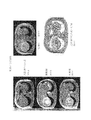
学習及び/又は活性化法則の群の選択によっても、明らかにされる情報の種類を変更することが可能である。一般的にこれら法則を2つの系統に分けることができる。この2つの系統を図3の系統図に示す。以下の詳細な説明において示すように、これら2つの系統にはそれぞれ名前がつけられている。 It is also possible to change the type of information revealed by selecting a group of learning and / or activation rules. In general, these laws can be divided into two systems. These two systems are shown in the system diagram of FIG. As shown in the detailed description below, each of these two systems is given a name.
法則の第1の系統は、重み進化及びユニット活性化を行い、デジタル或いはデジタル化されたソース画像から特徴を抽出する。これら特徴とは例えば、生体画像内の組織の種類、或いは組織などの物体の構造である。これにより、血管造影画像における血管狭窄部の有無を認識することが可能になる。 The first family of laws performs weight evolution and unit activation to extract features from a digital or digitized source image. These features are, for example, the type of tissue in the biological image or the structure of an object such as a tissue. This makes it possible to recognize the presence or absence of a vascular stenosis in an angiographic image.
第2の系統には基本的に、重み最適化を実行する法則が属する。重み最適化の後、更にユニット活性化が行われる。この種の法則は、画像の異なる領域の間にエッジを見出して、境界を認識するのに適する。このような境界としては例えば、生体組織の画像内の異なる種類の組織の間の境界が挙げられる。 The second system basically includes a law for performing weight optimization. After the weight optimization, further unit activation is performed. This kind of law is suitable for finding edges between different regions of the image and recognizing the boundaries. Examples of such a boundary include a boundary between different types of tissues in a biological tissue image.
本発明のアルゴリズムを適用できる分野は上記の例のほかにも存在する。別の例として、遺伝子間の関係或いは依存性を、その遺伝子の一般的な作用に関して評価することができる。 There are other fields to which the algorithm of the present invention can be applied in addition to the above examples. As another example, the relationship or dependence between genes can be assessed with respect to the general effects of that gene.
本発明はまた、デジタル或いはデジタル化画像の画像パタンを認識する方法に関する。 The invention also relates to a method for recognizing an image pattern of a digital or digitized image.
特に、本発明は、生体組織のデジタル或いはデジタル化画像内の異なる組織を認識及び区別する方法に関する。このような画像として、例えば、デジタル化された放射線或いは超音波画像、又は磁気共鳴画像などの診断画像が挙げられる。 In particular, the present invention relates to a method for recognizing and distinguishing different tissues in a digital or digitized image of biological tissue. Examples of such an image include a diagnostic image such as a digitized radiation or ultrasonic image, or a magnetic resonance image.
ここで説明する例は、特にデータ・レコードの2次元配列に関して説明されるが、本発明のアルゴリズム及び方法は、2次元空間に限らず、データ・レコードの3次元或いはN次元配列にも適用可能である。 The example described here will be described with particular reference to a two-dimensional array of data records, but the algorithm and method of the present invention is not limited to a two-dimensional space, but can be applied to a three-dimensional or N-dimensional array of data records. It is.
以下の詳細な説明において、図面を参照しつつ本発明のいくつかの実施例にしたがって本発明のアルゴリズム及び該アルゴリズムの使用方法を説明する。 In the following detailed description, the algorithm of the present invention and the method of using the algorithm will be described according to some embodiments of the present invention with reference to the drawings.
図1に示すごとく、データ・レコードの2次元配列は、矩形セルの配列として図式化される。各セルは、Piとして示される(iは自然数)。中央部の9つの矩形セルP7、P8、P9、P12、P13、P14及びP17、P18、P19は実線で描かれている。一方で、その他の周囲のセルは、破線で描かれている。これは、この配列が図示されている配列から拡大可能であることを示す。 As shown in FIG. 1, the two-dimensional array of data records is schematized as an array of rectangular cells. Each cell is shown as P i (i is a natural number). The nine rectangular cells P 7 , P 8 , P 9 , P 12 , P 13 , P 14 and P 17 , P 18 , P 19 in the center are drawn with solid lines. On the other hand, other surrounding cells are drawn with broken lines. This indicates that this arrangement can be expanded from the arrangement shown.
配列を構成するセルのそれぞれは、データ・レコードを表すセルである。データ・レコードは、配列内に該データ・レコードと一意的に関連付けられたセルを有することにより、配列内に一意的に関連付けられた位置を有する。データ・レコードのセルそれぞれのデータ・レコードのその他のセルに対する相対的位置は、対応するデータ・レコードの関連特性である。各セルのデータ・レコードのそれぞれは、値Uiを備える。尚、iは自然数であり、値Uiは、データ・レコードの1つの変数のみのパラメータ値であっても、或いはデータ・レコードを備えるベクトル、若しくは異なる変数の群のパラメータ値であってもよい。上記のような構造を、相対的位相情報を有するデータベースという。このようなデータベースにおいては、データ・レコードの値がデータ・レコードの関連特性であるだけでなく、データ・レコードの値がデータベースのデータ・レコードのn次元空間における射影に占める相対的位置、或いはデータベースのデータ・レコードのn次元マトリックスにおける配置の関連特性でもある。データ・レコードのn次元マトリックスは、このような射影を単に異なる形式で示したものにすぎない。 Each of the cells that make up the array is a cell that represents a data record. A data record has a position uniquely associated in the array by having a cell uniquely associated with the data record in the array. The relative position of each cell of the data record relative to the other cells of the data record is an associated characteristic of the corresponding data record. Each of the data records in each cell has a value U i . Note that i is a natural number, and the value U i may be a parameter value of only one variable of the data record, a vector having a data record, or a parameter value of a group of different variables. . Such a structure is referred to as a database having relative phase information. In such a database, not only is the value of the data record a relevant property of the data record, but also the relative position of the data record value in the projection of the data record of the database in the n-dimensional space, or the database It is also a related characteristic of the arrangement of the data records in the n-dimensional matrix. An n-dimensional matrix of data records is merely a representation of such projections in different forms.
例えば、デジタル或いはデジタル化された画像は、ピクセルの2次元配列である。各ピクセルはデータ・レコードの配列内の1つのデータ・レコードを表す。ピクセルの相対位置は、画像データの関連情報に属する各ピクセルの関連特性である。ピクセルの値は、グレースケール画像においては、単に明度を表す値であり、一方でカラー画像においては、少なくとも2つのパラメータ(具体的には色彩と明度)を備えるベクトルである。カラー画像を作成するために実際に使用されている技術においては、このベクトルは少なくとも3つのパラメータ或いは変数を備える。このような技術として、いわゆるHVS或いはRGBなどのカラー画像の符号化法が例示できる。 For example, a digital or digitized image is a two-dimensional array of pixels. Each pixel represents one data record in the array of data records. The relative position of the pixel is a related characteristic of each pixel belonging to the related information of the image data. The pixel value is simply a value representing brightness in a grayscale image, whereas in a color image it is a vector with at least two parameters (specifically color and brightness). In the technique that is actually used to create a color image, this vector comprises at least three parameters or variables. An example of such a technique is a so-called HVS or RGB color image encoding method.
図2は、本発明のアルゴリズムにしたがった、セルの2次元配列を人工ニューラルネットワークのセル或いはノットの配列に変換することにより、2次元配列のデータ・レコードを処理するための段階を示す。図中の矩形は図1の最初のセルPiとの関連を示し、矩形内部の円Kiは各セルPiから人工ニューラルネットワークのセル或いはノットの配列のユニット或いはノットKiへの変換或いは関連付けを示す。 FIG. 2 shows the steps for processing a two-dimensional array of data records by converting the two-dimensional array of cells into an array of artificial neural network cells or knots according to the algorithm of the present invention. The rectangle in the figure shows the relationship with the first cell P i in FIG. 1, and the circle K i inside the rectangle is a conversion from each cell P i to a unit of an array of cells or knots in an artificial neural network or knot K i . Indicates association.
結合の矢印wijはニューラルネットワークのユニット或いはノットKi及びKjの間の結合を表す。図2は図1の中央の9つのセルのみを示す。実際のターゲット・データ・レコードに対応するセルである中央のセルP13に向かう矢印は実線で示されている。一方で、周辺のセルへの結合を示す矢印は破線で示されている。本発明のアルゴリズムにより明らかに使用されるこれら周辺のセルへの結合のメカニズムは、中央の単一のセルP13について述べたように、本発明のアルゴリズムが動作する方法の記述から、個別にもたらされる。結合の両側に矢印が描かれているのは、周辺のセルに対して単一の中央のセルP13が動作する方法を記述することにより、この実際の中央のセルP13が、別のセルに対しては周辺のセルとなり、この別のセルが中央のセルとなることを表している。 The connection arrow w ij represents a connection between units of the neural network or knots K i and K j . FIG. 2 shows only the nine cells in the center of FIG. Actual target data record in towards the center of the cell P 13 is the corresponding cell arrows shown in solid lines. On the other hand, the arrow indicating the connection to surrounding cells is indicated by a broken line. Binding mechanism to the algorithm obviously used to be these peripheral cells of the present invention, as described for the center of a single cell P 13, the description of how the algorithm of the present invention operates, provided separately It is. Is the arrow is drawn on both sides of the binding, by describing how the single central cell P 13 against the periphery of the cell operates, cell P 13 of the actual center, another cell Indicates that this is a peripheral cell, and that this other cell is the center cell.
本発明のアルゴリズムをセルの配列に適用することにより、このアルゴリズムはセルの配列を構成するセルを1つずつ処理する。或るセルをその時点の中央のセルとして特定するとともに、それに対応する周辺のセル及びこの中央のセルと周辺のセルの間の関連する結合を特定する度に、このような処理が行われる。その時点で中央のセルとして特定されたセルについてこのような計算が終了すると、隣接するセルが新たな中央のセルとして定義されるとともに、この新たな中央のセルの周辺のセルが、対応する結合とともに周辺のセルとして新たに特定される。その後、この新たな中央のセルと、対応する結合を備える新たな周辺のセルに対して計算が行われる。このメカニズムは反復され、この配列の全てのセルについてアルゴリズムによる計算が行われると反復が終了する。そして人工ニューラルネットワークの第1計算サイクルが完了する。以降のサイクルは基本的に第1サイクルと同様であるが、以降のサイクルは、それ以前のサイクルにおいてアルゴリズムにより処理されたセルの配列に対して適用されるという点で相違している。 By applying the algorithm of the present invention to an array of cells, the algorithm processes the cells that make up the array of cells one by one. Such processing is performed each time a cell is identified as the current center cell and the corresponding surrounding cell and the associated connection between the center cell and the surrounding cell. When such a calculation is completed for the cell identified as the central cell at that time, the neighboring cell is defined as the new central cell, and the cells around this new central cell At the same time, it is newly specified as a peripheral cell. A calculation is then performed on this new central cell and a new peripheral cell with the corresponding combination. This mechanism is repeated, and the iteration ends when the algorithmic calculations are performed for all cells of this array. This completes the first calculation cycle of the artificial neural network. The subsequent cycles are basically the same as the first cycle, with the difference that the subsequent cycles apply to the array of cells processed by the algorithm in the previous cycle.
図13は本発明の人工ニューラルネットワークのセル或いはノットを示す概略図である。各ノット或いはセルKiはインプットを備え、このインプットにおいて、ノット或いはセルKiは他のノットKjからの出力信号ujを受信する。更に、各ノット或いはセルKiはアウトプットuiを備える。アウトプットuiは、1若しくはそれ以上のその他のノット或いはセルKjのインプットと結合される。各セル或いはノットのアウトプットuiは内部値Ai或いはノットKiの状態すなわち活性値の関数である。活性値の関数は、恒等関数であってもよい。すなわち、Ai=uiであってもよい。 FIG. 13 is a schematic diagram showing a cell or knot of the artificial neural network of the present invention. Each knot or cell K i has an input at which the knot or cell K i receives an output signal u j from another knot K j . Furthermore, each knot or cell K i has an output u i . The output u i is combined with the input of one or more other knots or cell K j . The output u i of each cell or knot is a function of the state of the internal value A i or knot K i , ie the activation value. The function of the activity value may be an identity function. That is, A i = u i may be used.
本発明の人工ニューラルネットワークにおいて、各ノット或いはセルKiはそのノット或いはセルの初期化値或いは活性値、若しくは初期化出力値uiを備えてもよい。この場合、図1、図2、及び図13の例に示すごとく、ノットKiの内部値或いは活性値Ai若しくはノットKiの最初の出力値uiのための初期化値は、データ・レコードPiの値uiと等しい値として設定される。上述のごとく、データ・レコードPiは、ノットKiと一意的に関連付けられている。ノット或いはセルKiのそれぞれは、更に、算出値Ui nのためのアウトプットを備える。値Ui nは、一連の特定の数mの処理サイクルのうちn番目の処理サイクルが終了後のデータ・レコードPiのための値である。計算された新たな値Ui nは、n番目のサイクルが実行された後のノット或いはセルKiの内部値或いは活性値Ai n、若しくはn番目のサイクルが実行された後のノット或いはセルKiの出力値Ui nと対応する。 In the artificial neural network of the present invention, each knot or cell K i may include an initialization value or activation value of the knot or cell, or an initialization output value u i . In this case, FIG. 1, as shown in the example of FIG. 2, and FIG. 13, the initialization value for the first output value u i of the internal value or activity value A i or knot K i of the knot K i is data It is set as a value equal to the value u i of the records P i. As described above, the data record P i is uniquely associated with the knot K i . Each knot or cell K i further comprises an output for the calculated value U i n . The value U i n is, n-th processing cycle of the series of processing cycles of a particular number m is a value for the data record P i after completion. The calculated new value U i n is the knot after the nth cycle is executed or the internal value or activation value A i n of the cell K i , or the knot or cell after the nth cycle is executed. Corresponds to the output value U i n of K i .
図2に示すごとく、本発明の人工ニューラルネットワークは、ノット或いはセルKiとノット或いはセルKiに直接隣接するノット或いはセルKjの間にのみ直接的な結合を備える。ノット或いはセルKjの群は、ノット或いはセルKiの局所的近傍(local neighbourhood)、すなわちグラディエント1(gradient 1)のノット或いはセルとして定義される。グラディエント1とは、基準となるノット或いはセルKiの位置と、ノット或いはセルKiの局所的近傍を形成するノット或いはセルKjの群の位置の間の段階的な差を表す。この定義は直感的に理解可能な定義として広く用いられている定義である。配列を構成する要素に対して、離散的な位置のみが与えられているような離散化された配列においては、基準となる要素を定義すると、基準となる要素の位置から、任意の方向にステップ1異なる位置を有する要素の群により、グラディエント1の近傍が形成される。以上は最も単純な例である。グラディエント1との語は、より一般的な意味においては、空間的座標だけではなく、n次元データベースが射影される任意の種類の空間についても言及できる。
As shown in FIG. 2, the artificial neural network of the present invention includes only a direct coupling between the knots or cell K i and knot or cell K directly adjacent to i knot or cell K j. A group of knots or cells K j is defined as a knot or cell of the local neighborhood of knots or cell K i , ie,
ノットKiと局所的近傍のノットKjの間の結合は、これら結合の強度により定義される。結合の強度は、これら局所的近傍のノットの信号がこれらノットに結合される基準となるノットKiに送られるとき、重みwji或いはwijにより量的に与えられる。重みwji或いはwijは、ノットKiの局所的近傍であるノット或いはセルKjのアウトプットを乗ぜられる。上で述べたように、基準ノットKiへ入力される重みを付加されたこれらの信号は、内部状態Aiに影響を与えて、出力信号uiを送信する或いは送信を禁止するか、若しくは出力信号uiの値を変更する。 The bond between knots K i and locally neighboring knots K j is defined by the strength of these bonds. The strength of the coupling is given quantitatively by the weights w ji or w ij when the signals of these locally neighboring knots are sent to the reference knot K i to be coupled to these knots. The weight w ji or w ij is multiplied by the output of a knot or cell K j that is a local neighborhood of the knot K i . As noted above, if these signals are added the weight to be input to the reference knot K i may influence the internal state A i, prohibits the transmission to or transmitting an output signal u i, or The value of the output signal u i is changed.
上で述べたように、このようなニューラルネットワークは処理の基礎として、ノット或いはセルの値だけではなく、これらをノット或いはセルの間の関係、及びこれらノット或いはセルの値とこれらの関係の間の相互作用も考慮する。 As mentioned above, such neural networks are based not only on knots or cell values, but also on the relationship between knots or cells, and between these knots or cell values and their relationship. Consider the interaction.
上記で1つの極端な例を一般的に論じたが、このうちの1つの例においては、ノット或いはセルKiの内部値Ai或いは出力値uiの最初の又は開始時の量的値Uiから開始して、ノット或いはセルKiの内部値Ai或いは出力値uiの進化が、結合wjiのみの関数として考慮される。量的値Uiは対応するノットKiに一意的に関連付けられたデータ・レコードPiの値である。この初期の又は開始時の値Uiはプロセスのインパルスの唯一の効果を有する。この進化の特徴の1つは、結合wjiの進化を制御する段階が結合の空間において起こることである(式4b)。この空間において、ノット或いはセルの進化に対して解が求められる。ノット或いはセルKiの開始値は、結合wijの進化に対する単純な制約として機能する。これら結合はノット或いはセルの値を動的に提供する。よって、このようなプロセスの誘引要素(actracting element)は、任意のノット或いはセルKiを限定的な関係を有する要素として新たに定義することである。この限定的な関係を有する要素は、ノット或いはセルKiの開始値Ui或いは局所的近傍を形成する隣接するノット或いはセルKjの開始値Ujの間の動的交渉により作り出される。 One extreme example was generally discussed above, but in one of these examples, the initial or starting quantitative value U of the internal value A i or the output value u i of the knot or cell K i. starting from i, the evolution of internal values a i or the output value u i of the knot or cell K i is considered as a function of only the bonds w ji. The quantitative value U i is the value of the data record P i uniquely associated with the corresponding knot K i . This initial or starting value U i has the sole effect of the impulse of the process. One of the characteristics of this evolution is that the step controlling the evolution of the binding w ji occurs in the space of the binding (Equation 4b). In this space, a solution is required for the evolution of knots or cells. The starting value of the knot or cell K i serves as a simple constraint on the evolution of the joint w ij . These combinations dynamically provide knot or cell values. Therefore, the attracting element of such a process is to newly define an arbitrary knot or cell K i as an element having a limited relationship. The element having a limiting relationship is created by the dynamic negotiation between the start values U j adjacent knots or cell K j to form a start value U i or local neighborhood of knots or cell K i.
結合を量的に定義する重みwjiは、局所的近傍Kj及び/又は基準ノットKiの内部値の関数である。 The weight w ji that quantitatively defines the coupling is a function of the local neighborhood K j and / or the internal value of the reference knot K i .
上記で一般的に論じた第2の極端な例においては、活性値Ai及びAj、或いは出力値ui及びujとしてのノット或いはセルの値のみが進化する。一方で、重みwjiにより表されるノット或いはセルの結合は一定に保たれる。この結合は進化プロセスの制約として機能する。 In the second extreme example, discussed generally above, only the values of knots or cells as active values A i and A j or output values u i and u j evolve. On the other hand, the knot or cell combination represented by the weight w ji is kept constant. This combination serves as a constraint on the evolutionary process.
ノットの重みwji及び値uiを決定する方法は、式の群により与えられる。この式は、法則とも呼ばれる。 The method of determining the knot weight w ji and the value u i is given by the group of equations. This formula is also called a law.
一般的に、重みの量的値を定義する式は、学習法則と呼ばれ、一方でノットの内部状態、活性値、或いは出力値を、基準ノット及びその局所的近傍を形成する隣接するノットの出力値の関数として変更する式は、活性化法則と呼ばれる。 In general, the expression that defines the quantitative value of the weight is called the learning law, while the knot's internal state, activity value, or output value is taken as the reference knot and the adjacent knots that form its local neighborhood. The formula that changes as a function of the output value is called the activation law.
上記で説明したように、学習法則或いは関数の群のみを考慮して計算が実行されてもよい。学習法則或いは関数は、結合の新たな重みwijを中央のセル及び周囲のセルのアウトプットの関数として定義することにより、実際の中央のセルPiの新たなアウトプットを計算する。中央のセル及び周囲のセルのアウトプットとは、これらセルに対応するデータ・レコードの1つの変数或いは複数の変数の値である。中央のセルの新たなアウトプットはその後、中央のセルの1若しくは複数の変数の1若しくは複数の新たな値として設定される。中央のセルのこの新たなアウトプットは、周囲のセルのアウトプットの関数である。周囲のセルのアウトプットとは、これら周囲のセルに対応するデータ・レコードの1若しくは複数の変数の値或いは、本発明のアルゴリズムにより計算された新たな重みの値である。 As explained above, the calculation may be performed considering only the learning law or the group of functions. The learning law or function calculates the new output of the actual center cell P i by defining the new weight w ij of the join as a function of the output of the center cell and surrounding cells. The outputs of the center cell and the surrounding cells are the values of one variable or a plurality of variables of the data record corresponding to these cells. The new output of the central cell is then set as one or more new values of one or more variables of the central cell. This new output of the center cell is a function of the output of the surrounding cells. The output of surrounding cells is the value of one or more variables in the data record corresponding to these surrounding cells, or the value of a new weight calculated by the algorithm of the present invention.
第1サイクルの計算の間、人工ニューラルネットワークのノットKi及びKjとして使用されるセルPiとPjの間の結合の重みwijは全て、特定の1つの値に等しい値に設定される。この値は例えば、1或いは0.0001などの任意の値として定められる。 During the calculation of the first cycle, the connection weights w ij between the cells P i and P j used as the knots K i and K j of the artificial neural network are all set to a value equal to one particular value. The This value is determined as an arbitrary value such as 1 or 0.0001.
この重みにしたがって、実際の中央のセルPi(図2のセルP13)の値は、周囲のセルPjの値及び結合wijの重みの関数として変更される。セルP13は人工ニューラルネットワークのユニット或いはノットK13として機能する。セルPjもまた、人工ニューラルネットワークのノットKjとして設定される。図2においてノットKjは、セル及びノットP7、P8、P9、P12、P14並びにP17、P18、P19、及びK7、K8、K9、K12、K14並びにK17、K18、K19である。 According to this weight, the value of the actual central cell P i (cell P 13 in FIG. 2) is changed as a function of the value of the surrounding cell P j and the weight of the combined w ij . Cell P 13 functions as a unit or knot K 13 ANN. Cell P j is also set as knot K j of the artificial neural network. Knot K j is the cell and knots P 7, P 8, P 9 , P 12, P 14 and P 17, P 18, P 19 , and K 7, K 8, K 9 in FIG. 2, K 12, K 14 And K 17 , K 18 , and K 19 .
ユニット或いはノットKiの新たなアウトプットを計算する別の方法として、活性化関数或いは法則の群を用いる方法がある。活性化関数或いは法則は、中央のノットK13のアウトプットをセルPj(図2におけるP7、P8、P9、P12、P14、及びP17、P18、P19)のデータ・レコードの値Uj(図2におけるU7、U8、U9、U12、U14、及びU17、U18、U19)の関数として定義する。セルPjは中央のセルPiを取囲むセルであり、中央のセルPiはユニット或いはノットKiに対応するとともに、重みwijの関数として活性化される。この場合新たな重みwijは計算されない。 Another way to calculate the new output of a unit or knot K i is to use an activation function or a group of laws. Activation function or law, data output cells P j of the central knot K 13 (P 7, P 8 in FIG. 2, P 9, P 12, P 14, and P 17, P 18, P 19 ) Define as a function of the record value U j (U 7 , U 8 , U 9 , U 12 , U 14 and U 17 , U 18 , U 19 in FIG. 2). The cell P j is a cell surrounding the central cell P i , and the central cell P i corresponds to a unit or knot K i and is activated as a function of the weight w ij . In this case, a new weight w ij is not calculated.
結合に対する新たな重みwijを計算する学習法則の特定の群と、各サイクルにおける新たな出力値を計算する活性化法則の特定の群を用いて、複合的な計算を行ってもよい。 A complex calculation may be performed using a specific group of learning rules for calculating a new weight w ij for the combination and a specific group of activation rules for calculating a new output value in each cycle.
したがって、1つのサイクルが完了するまでに、新たなアウトプット、すなわちデータ・レコードの配列内の各データ・レコードのための変数の新たな値及び結合のための新たな重みが計算されている。これらのデータ・レコードの1若しくは複数の変数の新たな値及び結合の重みの新たな値はいずれも、続く計算サイクルにおいて用いられる。 Thus, by the end of one cycle, a new output has been calculated, a new value for the variable for each data record in the array of data records and a new weight for the combination. Both the new value of one or more variables of these data records and the new value of the coupling weight are used in the subsequent calculation cycle.
図2の例に示すごとく、関数により周囲のノットK7、K8、K9、K12、K14及びK17、K18、K19のアウトプットU7、U8、U9、U12、U14及びU17、U18、U19を用いて、ノットK13のネット・インプットが定義される。アウトプットU7、U8、U9、U12、U14及びU17、U18、U19は中央のセルP13を取囲む関連するセルP7、P8、P9、P12、P14、及びP17、P18、P19及び関連するノットK13の値に対応する。アウトプットの以前の値と本発明のアルゴリズムにより計算された新たな値の差異に基づく更に別の関数が提供される。この関数は、中央のノットKi(図2におけるK13)と周囲のノットKj(図2におけるK7、K8、K9、K12、K14、及びK17、K18、K19)の間の結合のための新たな重みwijを定義する。 As shown in the example of FIG. 2, the outputs U 7 , U 8 , U 9 , U 12 of the surrounding knots K 7 , K 8 , K 9 , K 12 , K 14 and K 17 , K 18 , K 19 are represented by functions. , U 14 and U 17 , U 18 , U 19 are used to define the net input of knot K 13 . Outputs U 7 , U 8 , U 9 , U 12 , U 14 and U 17 , U 18 , U 19 are associated cells P 7 , P 8 , P 9 , P 12 , P surrounding the central cell P 13. 14 and P 17 , P 18 , P 19 and the associated knot K 13 values. Yet another function is provided based on the difference between the previous value of the output and the new value calculated by the algorithm of the present invention. This function consists of a central knot K i (K 13 in FIG. 2) and a surrounding knot K j (K 7 , K 8 , K 9 , K 12 , K 14 , and K 17 , K 18 , K 19 in FIG. 2). ) To define a new weight w ij for the connection between.
第1サイクルの最後、つまり全てのセルが上記の手順に従って処理された後には、セルの新たな配列が構築されている。この新たな配列においては、データ・レコードはそのセルを維持しているとともに、各データ・レコードは、1若しくは複数の変数のための上記のごとく第1サイクルにおいて計算された新たな値を備える。またこのとき、結合のための新たな重みも既に計算されている。 At the end of the first cycle, ie after all cells have been processed according to the above procedure, a new array of cells has been constructed. In this new array, the data record maintains its cell and each data record comprises the new value calculated in the first cycle as described above for one or more variables. At this time, a new weight for combination has already been calculated.
第2サイクルは、データ・レコードのこの新たな配列を用いて実行される。第2サイクルにおいては、第1サイクル或いは以前のサイクルにおいて、セルに対応する人工ニューラルネットワークのノットのアウトプットとして計算されたデータ・レコードの値、及び上記のように第1或いは以前のサイクルにおいて計算されているセルに対応するノット間の結合のための新たな重みが用いられる。第2或いはそれ以降のサイクルにおいては、ノットの新たなアウトプット及びデータ・レコードの新たな値が計算され、これによりデータ・レコードの新たな配列が形成される。この新たな配列においては、データ・レコードは、更新された値を備える。同様に、ノット間の結合のための対応する新たな値が計算され、アルゴリズムの以降のサイクルが提供されるか、或いは必要である場合には、これらサイクルにおいて用いられる。 The second cycle is performed using this new array of data records. In the second cycle, the value of the data record calculated as the knot output of the artificial neural network corresponding to the cell in the first or previous cycle, and calculated in the first or previous cycle as described above. New weights are used for combining between knots corresponding to the cell being processed. In the second or subsequent cycle, the new output of the knots and the new value of the data record are calculated, thereby forming a new array of data records. In this new array, the data record comprises the updated value. Similarly, corresponding new values for the knot-to-knot coupling are calculated and subsequent cycles of the algorithm are provided or used in these cycles if necessary.
以降のサイクルの数(n)は、固定されたパラメータとして決定されてもよい。若しくは、反復回数は、データ・レコードの新たな配列の値と最初の値についての誤差或いは逸脱(deviance)の計算により決定されてもよい。この計算においては、最大誤差或いは逸脱が設定される。この計算は、人工ニューラルネットワークの分野における通常の誤差或いは逸脱の計算を用いて行われてもよい。 The number of subsequent cycles (n) may be determined as a fixed parameter. Alternatively, the number of iterations may be determined by calculating the error or deviance for the new array value and the initial value of the data record. In this calculation, the maximum error or deviation is set. This calculation may be performed using normal error or deviation calculations in the field of artificial neural networks.
別の重要な点として、データ・レコードの変数のための一連の新たな値の差がモニタされ、一連のサイクルにおけるこの新たな値の差が、有意な差ではなくなったときに、アルゴリズムの反復が停止される。値の差が有意ではないとはすなわち、この差が所定の値より小さいことをいう。値の差が有意ではないとはまた、新たな値と以前の値にほとんど差がないことをいう。ほとんど差がないか否かは、データ・レコードの変数の値及びデータ・レコードの種類にしたがって判断される。データ・レコードの種類を考慮するのは、極小さな差が、ある場合においてはデータ・レコードの情報に対して大きな影響を及ぼすこともある一方で、その他の場合においてはそれほど大きな影響を及ぼさないこともあるからである。 Another important point is that the series of new value differences for the variables in the data record are monitored and the algorithm iterations when this new value difference in the series of cycles is no longer significant. Is stopped. That the difference in values is not significant means that this difference is smaller than a predetermined value. A difference in value is not significant also means that there is little difference between the new value and the previous value. Whether there is almost no difference is determined according to the value of the variable in the data record and the type of the data record. Considering the type of data record is that a very small difference can have a large impact on the information in the data record in some cases, but not so much in other cases. Because there is also.
以下では、人工ニューラルネットワークのノットのアウトプット、すなわち対応するデータ・レコードの値を更新するとともに、結合の重みを更新するための法則の例を示す。この法則或いは関数に名前を付して、特定の法則の説明において法則を識別しやすくする。 In the following, an example of a rule for updating the knot output of the artificial neural network, that is, the value of the corresponding data record and updating the weight of the connection is shown. Name this law or function to help identify the law in the description of a particular law.
明らかにされる或いは強化される情報の種類は、元の画像のピクセル配列により形成されるニューラルネットワーク構造に適用される学習及び/又は活性化法則の群の種類により決定される。基本的に、得られる効果は、超音波、放射線、核磁気共鳴、或いはこれに類する撮像方法における造影剤のようなコントラストを増強する材料を用いて得られる効果と同様である。 The type of information that is revealed or enhanced is determined by the type of learning and / or activation laws applied to the neural network structure formed by the pixel array of the original image. Basically, the obtained effect is the same as the effect obtained by using a material that enhances contrast, such as a contrast agent in ultrasound, radiation, nuclear magnetic resonance, or the like.
学習及び/又は活性化法則の特定の群を選択することにより、強化される情報の種類は更に変更可能である。一般的にこれら法則の群を2つの系統に分けられる。2つの系統は図3の系統図に示されている。この系統図において、法則の異なる群は、以下で説明する名前により識別されている。 By selecting specific groups of learning and / or activation laws, the type of information that is enhanced can be further changed. Generally, these groups of laws can be divided into two systems. The two systems are shown in the system diagram of FIG. In this system diagram, different groups of laws are identified by the names described below.
第1の系統には、基本的に重み最適化を行う法則が分類される。重み最適化は、更に、ユニット活性化と組み合わされてもよい。この種の法則は、画像の異なる領域間のエッジを見出し、境界を特定するのに役立つ。境界とは例えば、生体画像における異なる種類の組織の間の境界である。 In the first system, a rule for performing weight optimization is basically classified. Weight optimization may be further combined with unit activation. This type of law helps find edges between different regions of the image and identify boundaries. The boundary is, for example, a boundary between different types of tissues in the biological image.
一般的な種類の群の法則は、オートマータ法則(Automata Rule、A或いはAR)と呼ばれる。これら法則は、最適化された重みを決定するための関数、すなわち学習法則を備える。以下の2つの群の法則を用いることができる。 A general type of group law is called Automata Rule (A or AR). These laws comprise a function for determining optimized weights, ie a learning law. The following two groups of rules can be used.
ただし式14において、σ:アルゴリズムの画像の差異に対する感度を向上或いは低下させるための使用者により自由に定義可能なパラメータ、Rij:i番目のユニットからj番目のユニットまでの距離、Ui:人工ニューラルのノットKiに変換された単一のセルPiの値、添え字i:中央のセル或いはノット、添え字j:前記中央のセル或いはノットを直接取囲むセル或いはノットとする。 However, in Expression 14, σ: a parameter that can be freely defined by the user for improving or decreasing the sensitivity to the image difference of the algorithm, R ij : distance from the i-th unit to the j-th unit, U i : The value of a single cell P i converted to an artificial neural knot K i , subscript i: a center cell or knot, subscript j: a cell or knot directly surrounding the center cell or knot.
図3に示すごとく、この一般的な法則を特殊化或いは強化して、異なる法則の群を得ることも可能である。 As shown in FIG. 3, it is also possible to specialize or strengthen this general law to obtain different groups of laws.
上記のオートマータ法則は、各ターゲットすなわちノット又はセルKiと、局所的近傍のノット又はセルKjのそれぞれの間の結合強度を、これらノット又はセルの異なる値uiとujの差の非線形射影として定義する。よって基準ノット又はセルKiのそれぞれは、8つの対称な重みwjiにより、グラディエント1の局所的近傍であるノット又はセルKjと結合される。全ての2次元データベース(例えば2次元画像)はマトリックスにより形成される。このマトリックスにおいて、マトリックスを構成する要素のそれぞれは、自立的ユニットとして、その局所的近傍と結合される。局所的近傍とは、マトリックスの基準要素に直接隣接する要素である。データの2次元マトリックス配列(例えば画像)は、マトリックスの各要素と局所的近傍の要素の間の特定数の対称な結合により更に結合される。
The automata law described above determines the coupling strength between each target, i.e., knot or cell K i, and each of the locally neighboring knots or cell K j , the nonlinearity of the difference between the different values u i and u j of these knots or cells. Define as a projection. Thus, each reference knot or cell K i is combined with a knot or cell K j that is a local neighborhood of
上記の式により定義される結合wjiの量的強度値は、制約を形成する。これにより、結合強度のアクティブ・マトリクスからなる形態のデータ配列(例えば画像)は各セル又はノットの初期化値に進化を引き起こす。この進化は、所定のn番目の処理サイクルが終了するまで、ナチュラル・アクトラクタ(natural actractor)に向かって継続される。 The quantitative strength value of the bond w ji defined by the above equation forms a constraint. Thus, a data array (eg, image) in the form of an active matrix of bond strengths causes evolution to the initialization value for each cell or knot. This evolution continues towards the natural actractor until the predetermined nth processing cycle is completed.
第II群の法則は、一般的に制約充足(CS、Constraint Satisfaction)と呼ばれる。CSは以下のような様々な変更例に展開できる。 The group II law is generally called Constraint Satisfaction (CS). CS can be expanded into various modifications as follows.
(II.1.)いわゆるCS XORは次の式により表される。 (II.1.) So-called CS XOR is represented by the following equation.
ただし式15において、Ui:中央のノットKiのアウトプットとする。Uiはまた、i番目のノット或いはセルのインプットと初期化段階とを組み合わせたものとしても定義される。この定義は、ニューラルネットワークを実行する第1段階において、i番目のユニットが出力値として、デジタル化されたソース画像の対応するピクセルの値を備えることを強調する傾向にある。明らかに、ニューラルネットワークの開始段階において、この出力値はi番目のノット或いはセルに起因しなければならず、またこの出力値はインプットとしてみなされる。以降の計算サイクルにおいて、各ノット或いはセルの値は本発明のアルゴリズムにより変更され、特定回数の反復が完了したときには、i番目のノット或いはセルの値は入力画像のi番目のピクセルの値に対応しているか或いは関連付けられている。更に、式15において、Uj:周囲のノットKjのアウトプット、Neti:中央のノットKiのネット・インプット(周囲のノットKjのアウトプットUjと周囲のノットKjと中央のノットKiの結合の重みwijの関数として計算される)、n:サイクルの数、αi:中央のノットKiのアウトプットUiの更新値であり、次のサイクルのための新たなアウトプット値を、ネット・インプットNetiと中央のノットKiの実際のアウトプットUiの関数として計算するための値、α:定数とする。 However, in the formula 15, U i: the output of the central knot K i. U i is also defined as the combination of the input of the i-th knot or cell and the initialization phase. This definition tends to emphasize that in the first stage of executing the neural network, the i-th unit comprises the value of the corresponding pixel of the digitized source image as the output value. Obviously, at the start of the neural network, this output value must be attributed to the i-th knot or cell, and this output value is taken as input. In subsequent calculation cycles, the value of each knot or cell is changed by the algorithm of the present invention, and when a specific number of iterations is completed, the value of the i-th knot or cell corresponds to the value of the i-th pixel of the input image. Or are associated. Further, in the equation 15, U j: surrounding knots K j of the output, Net i: the central knot K i net input (around the knot K j output U j and the surrounding knots K j and central Calculated as a function of the connection weight w ij of knot K i ), n: number of cycles, α i : updated value of output U i of central knot K i , and the new value for the next cycle Let the output value be a value for calculating as a function of the net input Net i and the actual output U i of the central knot K i , α: constant.
(II.2)いわゆるCS ANDは次の式により表される。 (II.2) So-called CS AND is expressed by the following equation.
式16における文字の定義は、式15と同様である。この活性化関数と、式15の関数の相違点は、αiを計算するための関数が、α2として定義される項を備えることである。この項は式16において、活性化されたノットKiを除く全てのノットのアウトプットの平均の関数として定義される。
The definition of the character in
(II.3)いわゆるCS CONTESTは次の式により表される。 (II.3) The so-called CS CONTEST is expressed by the following equation.
式17における文字の定義は、式15及び16の活性化関数(1)及び(2)の例と同様である。
上記の例との相違点は、Neti<0である場合に、項αiが異なる方法で計算されることである。
The definition of the character in Expression 17 is the same as the activation functions (1) and (2) in
The difference from the above example is that the term α i is calculated differently when Net i <0.
(II.4)いわゆるHIGH CS XORは次の式により表される。 (II.4) The so-called HIGH CS XOR is expressed by the following equation.
式18における文字の定義は、式15及び16の活性化関数(1)及び(2)の例と同様である。ノットKiのネット・インプットNetiを計算するための関数が、上記の例と異なる。上記の式より明らかなように、この場合、結合の重みwijに関数α2が適用される。
中央のノットKiのアウトプットUiの更新値αiを計算するための関数は、活性化関数の第1の例と同一である。
The definition of characters in Equation 18 is the same as the examples of activation functions (1) and (2) in
Function for calculating the updated value alpha i of the output U i of the central knot K i is the same as the first example of the activation function.
(II.5)いわゆるHIGH CS ANDは次の式により表される。 (II.5) The so-called HIGH CS AND is expressed by the following equation.
式19の一連の式と、High CS XORと呼ばれる活性化関数(4)及びCS ANDと呼ばれる活性化関数(2)を比較すると明らかなように、式19の関数は、High CS XOR とCS ANDを組み合わせたものである。 As is clear from the comparison of the series of equations 19 with the activation function (4) called High CS XOR and the activation function (2) called CS AND, the function of equation 19 is expressed as follows: High CS XOR and CS AND Is a combination.
(II.6)いわゆるHIGH CS CONTESTは次の式により表される。 (II.6) The so-called HIGH CS CONTEST is expressed by the following equation.
この場合の関数も、上記の活性化関数、すなわちCS CONTESTと呼ばれる活性化関数(3)とHigh CS XORと呼ばれる活性化関数(4)を組み合わせた関数である。 The function in this case is also a function combining the above activation function, that is, the activation function (3) called CS CONTEST and the activation function (4) called High CS XOR.
上述の異なる法則の群は、1つの共通した一般的概念にしたがっている。2次元画像の例を用いて説明したように、基本的概念は、マトリックスの各ピクセルを、各ピクセルの明度により真或いは偽となる仮説とみなすことである。また、このシステムは、各ピクセルとその局所的近傍の間の局所的結合を継承している。この結合の強度は、重みを用いて表現され、この重みは、上記のオートマータ法則を用いて計算される。結合のアクティブ・マトリックスの進化の間、この結合は制約として機能する。上記の式によるシステムのコストの関数は、マトリックスの各仮説を真とすることを試みることにより、各ピクセルの明度を最大とすることである。このプロセスの間、それ以前に既に計算されている結合を定義する重みは、制約として機能する。
上記したことの例として、特定の境界線内のピクセルの動作を以下に示す。
The group of different laws mentioned above follows one common general concept. As explained with the example of a two-dimensional image, the basic concept is to regard each pixel of the matrix as a hypothesis that is true or false depending on the brightness of each pixel. The system also inherits a local connection between each pixel and its local neighborhood. The strength of this connection is expressed using a weight, which is calculated using the automata law described above. This bond serves as a constraint during the evolution of the active matrix of the bond. The system cost function according to the above equation is to maximize the brightness of each pixel by trying to make each hypothesis of the matrix true. During this process, the weights defining the bonds that have already been calculated before serve as constraints.
As an example of the above, the operation of a pixel within a specific boundary is shown below.
CSと呼ばれる法則の群とも異なる更に別の特殊な法則の群は、IAC(Interaction and Activation Competition)と呼ばれる第IIIの法則の群である。 Another group of special rules different from the group of rules called CS is a group of the third rule called IAC (Interaction and Activation Competition).
中央のノットKiのネット・インプットNetiは結合の重みwijが正か負かに基づいてネット・インプットを計算する2つの異なる関数の合計として定義される。具体的には、関数ecci及びiniiは同一であり、重みが正或いは負の結合に関連付けられるインプットが異なるのみである。この相違が、2つの関数ecci及びiniiにより表現されている。Netiのこれら2つの要素について、要素ecciは興奮或いは強化に関連付けられ、iniiは抑制に関連付けられる。ネット・インプットNetiはecci及びiniiを組み合わせたものであり、Netiにおいて、ecci及びiniiはそれぞれ、パラメータα及びパラメータβにより乗ぜられる。これら2つのパラメータは、重みが正の結合と、重みが負の結合のネット・インプットNetiへの影響を決定する。 Net Input Net i of the central knot K i is defined as a sum of two different functions weights w ij for coupling to compute the net inputs based on whether positive or negative. Specifically, the functions ecc i and ini i are the same, only the inputs associated with a combination of positive or negative weights. This difference is expressed by two functions ecc i and ini i. These two elements net Non i, element ecc i is associated with excitement or strengthening, ini i is associated with a suppression. Net Input Net i is a combination of ecc i and ini i, in Net i, ecc i and ini i, respectively, are multiplied by the parameter α and the parameter beta. These two parameters determine the effect on the net input Net i of the positive weight combination and the negative weight combination.
更に、活性化パラメータActiがノットKiへのネット・インプットNetiの関数として提供される。
このパラメータを用いて、ノットKiのアウトプットUiの更新値αiを計算する2つの異なる関数のうち1つが選択される。この選択は、Actiが正であるか負であるかに基づいて行われる。強化と抑制はαiを計算するための2つの関数に明らかに起因する。これは、これら関数にパラメータとしてActiが存在するからである。
これら関数には以下の表現が用いられる。
Max及びMinは、活性化法則の上限及び下限として定義される。
Decayは、各ユニットの時間にしたがった通常のディケイ値として定義される関数である。
Restは、各ユニットに対するデフォルト値として定義される。
ノットKiの新たな出力値は、特定の指数関数により定義される。この指数関数は、この例の活性化関数の興奮及び抑制メカニズムを増強する。
Furthermore, an activation parameter Act i is provided as a function of the net input Net i to knot K i .
Using this parameter, one of two different functions for calculating the updated value α i of the output U i of the knot K i is selected. This selection is made based on whether Act i is positive or negative. The enhancement and suppression are apparently due to two functions for calculating α i . This is because Act i exists as a parameter in these functions.
The following expressions are used for these functions.
Max and Min are defined as the upper and lower limits of the activation law.
Decay is a function defined as a normal decay value according to the time of each unit.
Rest is defined as a default value for each unit.
The new output value of knot K i is defined by a specific exponential function. This exponential function enhances the excitation and suppression mechanism of the activation function in this example.
一般的にピクセルの配列により形成される画像が、処理されるデータベースである場合、上記の式は、結合のアクティブ・マトリックスを定義する。このマトリックスにおいては、各ピクセルは、他のピクセルから、興奮及び抑制のインパルスを動的に受信するとともにこれに対応してその内部状態を変更するエージェントである。上記の式によるシステムは、エージェント・ピクセル間の集合的自動調整システムとして定義される。高い明度を有するピクセルが自らを支持する傾向にある一方で、その他のピクセルの明度がより低い値まで低下される。各エージェント・ピクセルとその局所的近傍の間の結合の一定した重みは、各ピクセル間の通信を調節する制約として機能する。この通信は、メッセージを励起及び抑制することにより形成される。進化は、個々のステップにより、元の画像の変換を引き起こす。元の画像においては、急激に明度が変化しているピクセルは、孤立状態とされ、その明度が低い値まで低下される。よって、システム全体は、画像内に存在するエッジを強調するというタスクのための特別な関数を用いることなく、このタスクを実行できる。ピクセルが互いに競合している場所においては、ある種の壁が視覚化される。この壁は、異なる図形間の壁として通常認識される。上記の法則からなるシステムの利点は、局所的自動調整(local auto-coordination)に起因したエッジ検出効果を有することである。更に、適応閾値フィルタとしての機能が現れる。各エッジについて、1つの直線が提供される。この直線の太さは、画像がそれぞれの領域において示す局所的明度の差に対応する。 In general, if the image formed by the array of pixels is the database being processed, the above equation defines an active matrix of joins. In this matrix, each pixel is an agent that dynamically receives excitement and suppression impulses from other pixels and correspondingly changes its internal state. The system according to the above equation is defined as a collective automatic adjustment system between agent pixels. While pixels with high brightness tend to support themselves, the brightness of other pixels is reduced to lower values. The constant weight of the bond between each agent pixel and its local neighborhood serves as a constraint that regulates the communication between each pixel. This communication is formed by exciting and suppressing messages. Evolution causes transformation of the original image by individual steps. In the original image, pixels whose brightness has been changed abruptly are in an isolated state and their brightness is reduced to a low value. Thus, the entire system can perform this task without using a special function for the task of enhancing edges present in the image. In places where pixels are competing with each other, certain walls are visualized. This wall is usually recognized as a wall between different figures. The advantage of the system consisting of the above laws is that it has an edge detection effect due to local auto-coordination. Furthermore, a function as an adaptive threshold filter appears. One straight line is provided for each edge. The thickness of this straight line corresponds to the difference in local brightness that the image shows in each region.
上記の法則の群とは異なるPixel Mexican Hat PmHと呼ばれる群(第IV群である)は以下の式により表される。 A group called “Pixel Mexican Hat PmH” (which is a group IV), which is different from the above group of laws, is represented by the following formula.
式22における文字の定義は、上記のIACと呼ばれる第III群における定義と同様である。
比較的特殊化された群II.1乃至II.6、III、及びIVと、ARと呼ばれる一般的な法則の群の相違点は、重み最適化だけでなく、ユニット活性化も実行されることである。
The definition of characters in Formula 22 is the same as the definition in Group III called IAC above.
A relatively specialized group II. 1 to II. The difference between 6, III, and IV and the general rule group called AR is that not only weight optimization but also unit activation is performed.
この法則の群は、局所的閾値及び適応閾値を有する拡大レンズとして機能する。画像にもたらされる効果として、全てのピクセル間の明度に関する対立が最小限であると同時に、各ピクセルが一定且つ均一な明度を有しながら、これら全てのピクセルが強調される。これにより、通常目視できないエッジを照らし出すという視覚的効果が得られる。 This group of laws functions as a magnifying lens with local and adaptive thresholds. The effect on the image is that all of these pixels are enhanced while each pixel has a constant and uniform lightness while at the same time there is minimal conflict between all pixels. This provides the visual effect of illuminating edges that are normally not visible.
法則の第2の系統は、重み進化及びユニット活性化を行い、デジタル或いはデジタル化されたソース画像から特徴を抽出する。これら特徴とは例えば、生体画像内の組織の種類、或いは組織などの物体の構造である。これにより、血管造影画像における血管狭窄部の有無を認識することが可能になる。 The second family of laws performs weight evolution and unit activation to extract features from a digital or digitized source image. These features are, for example, the type of tissue in the biological image or the structure of an object such as a tissue. This makes it possible to recognize the presence or absence of a vascular stenosis in an angiographic image.
学習及び活性化法則の群の2つの下位集団が提供される。 Two subgroups of groups of learning and activation laws are provided.
第1に、第V群として示されるいわゆるCM(Contractive map)は、学習フェーズ及び再生フェーズを備える再循環ニューラルネットワーク(recirculation neural network)として定義可能である。(詳しくは、「Reti neurali artificiali e sistemi sociali complessi」(Massimo Buscema、Semeion Group著、Semeion Centro ricerche、Franco Angeli Milano、第1巻、Edizione Franco Angeli Milano、1999年を参照。)
First, a so-called CM (Contractive map) shown as the V-th group can be defined as a recirculation neural network having a learning phase and a reproduction phase. (For details, see “Reti neurali artificial esistemi sociali complessi” (see Massimo Buscema, Semeion Group, Semeion Centro ricerche, Franco Angeli Milano,
CMと呼ばれる法則の第V群は、以下の関数を備える。 The V group of the law called CM comprises the following functions.
グレースケール画像のみについていうと、各ピクセルの値、すなわち対応するユニットそれぞれのアウトプットは、グレースケール・レベルの数で除算される。 For grayscale images only, the value of each pixel, ie the output of each corresponding unit, is divided by the number of grayscale levels.
256のグレースケール・レベルが存在する場合には、各ピクセルの値はこの数により除算される。この除算の解の整数部分のみを考慮すると、この除算により、ピクセルすなわちユニットが属する分類の数を表す数が減少されるとともに余りがもたらされる。この余りは変数remにより示される。 If there are 256 grayscale levels, the value of each pixel is divided by this number. Considering only the integer part of this division solution, this division reduces the number representing the number of classifications to which the pixel or unit belongs and provides a remainder. This remainder is indicated by the variable rem.
この種の操作により、ユニットすなわちピクセルが属する分類の数を減少させることができる。よって、これら分類に均一な色彩或いはグレー・レベルを付与することにより、各分類を、出力画像として視覚化することが可能である。余りすなわちremの値を更に用いて、色彩或いはグレー・レベルの強度が変更される。例えば、ピクセル或いはユニットの4つの分類を考えると、各分類は例えば、赤、緑、青、黄の色彩、或いは4つのグレー・レベルを付与される。各ピクセルの余りを用いると、各色彩を、例えば暗い赤から、明るい又は薄い赤までなどのように変化させることができる。これにより、同じ分類の出力画像のピクセルを更に変化させることが可能になる。 This type of operation can reduce the number of classifications to which a unit or pixel belongs. Therefore, by assigning a uniform color or gray level to these classifications, each classification can be visualized as an output image. The remainder or rem value is further used to change the intensity of the color or gray level. For example, considering four classifications of pixels or units, each classification is given, for example, red, green, blue, yellow colors, or four gray levels. With the remainder of each pixel, each color can be changed, for example, from dark red to bright or light red. This makes it possible to further change the pixels of the output image of the same classification.
rem関数は、ユニットのアウトプット及び出力画像のピクセルに与えられる値を、特定の値の範囲内で調節する関数であるといえる。この範囲は、quot関数により定義される各分類を特徴付ける。 The rem function can be said to be a function that adjusts the values given to the output of the unit and the pixels of the output image within a range of specific values. This range characterizes each classification defined by the quot function.
quot及びrem関数は、カラー・ピクセルに対応するピクセル値にも適用できる。この場合、ピクセル値は通常、3つのパラメータを有するベクトルである。これらパラメータとしては例えば、カラー・ピクセルの値のRGB定義、或いはHSV、若しくはこれに類するものが挙げられる。 The quot and rem functions can also be applied to pixel values corresponding to color pixels. In this case, the pixel value is usually a vector with three parameters. Examples of these parameters include RGB definition of color pixel values, HSV, or the like.
上記の式から明らかなように、ピクセル値及び対応するニューラルネットワークに変換されたユニットの出力値は初めに正規化される。これにより、出力値を0以上1以下の範囲に維持することが可能になる。 As is apparent from the above equation, the pixel values and the output values of the units converted to the corresponding neural network are first normalized. As a result, the output value can be maintained in the range of 0 to 1.
quot関数及び対応するrem関数により分類の定義が行われる間、出力値は再び非正規化される。すなわち、0以上1以下の範囲から、元の範囲に再スケール設定される。 While the classification is defined by the quot function and the corresponding rem function, the output value is denormalized again. That is, the rescale is set from the range of 0 to 1 to the original range.
quot関数による関数の分類及びrem関数による調節を用たり、或いはニューラルネットワークのユニットの出力値を非正規化することなく、且つニューラルネットワークのユニットの値或いは出力画像の上記したピクセル値と相関したグレースケール或いは色彩スケールを定義することにより、「CM true color」と定義される変更された法則を得ることが可能である。これに対して、その他の法則は、quot関数による分類のみが適用される場合には「CM quot」、rem関数がquot関数と併せて適用される場合には「CM quot+rem」と定義される。 Gray that correlates with the value of the unit of the neural network or the above-mentioned pixel value of the output image without using the classification of the function by the quot function and the adjustment by the rem function or denormalizing the output value of the unit of the neural network. By defining a scale or color scale, it is possible to obtain a modified law defined as “CM true color”. On the other hand, the other laws are defined as “CM quot” when only the classification by the quot function is applied, and “CM quot + rem” when the rem function is applied together with the quot function.
ピクセルの配列からなる画像の例についていうと、上記の法則の群の基本的な概念は、処理が各ピクセルの初期化値から開始され、この値がサイクルを通して不変の値であることである。進化は、結合を定義する重みに対して起こり、各処理サイクルにおいて、各ピクセルが、この重みの関数として明度の新たな値をとる。この重みは、現在の瞬間におけるピクセルを特徴付ける。基準ピクセルとその局所的近傍のピクセルの間の結合は、双方向性の結合である。各ピクセルは、別のピクセルと通信するための第1の結合、及びこの別のピクセルからの通信を受信するための第2の結合を備える。 For the example of an image consisting of an array of pixels, the basic concept of the above set of rules is that the process starts with an initialization value for each pixel, and this value is a constant value throughout the cycle. Evolution occurs for the weights that define the join, and in each processing cycle, each pixel takes a new value of brightness as a function of this weight. This weight characterizes the pixel at the current moment. The coupling between the reference pixel and its locally neighboring pixels is a bidirectional coupling. Each pixel comprises a first combination for communicating with another pixel and a second combination for receiving communication from this other pixel.
結合を定義する重みの進化法則は、この決定性の法則の群に属し、重みはほぼゼロに等しい値により初期化される。 The weight evolution law defining the bond belongs to this group of deterministic laws, and the weight is initialized with a value approximately equal to zero.
各処理サイクルの各ピクセルの明度の新たな値は、重みの空間内において定義される。よって各ピクセルの値のそれぞれは、そのピクセルとそのピクセルの局所的近傍の結合を定義する重みにより定義される。 A new value for the lightness of each pixel in each processing cycle is defined in the weight space. Thus, each pixel value is defined by a weight that defines the combination of that pixel and its local neighborhood.
更に別の法則の群、すなわち第VI群は、Local Sine LSとして定義される。この群も、法則の群の上記の第2の系統に属する。 Yet another group of laws, namely Group VI, is defined as Local Sine LS. This group also belongs to the above-mentioned second family of law groups.
Local sineと呼ばれる群には、2つの異なる群が存在する。これらはそれぞれ、Local Sine 1 LS1及びLocal Sine 2 LS2と呼ばれる。これら2つの群は1つの式についてのみ異なり、これらの群は以下の式により表される。
There are two different groups in the group called Local sine. These are called
式24における文字の定義は、第I乃至第Vの法則の群における定義と同様である。ただし、Dijはi番目のユニットとj番目のユニットの間の或る種の距離、αは標準偏差を表す。 The definition of the character in Expression 24 is the same as the definition in the group of the first to Vth laws. Where D ij represents a certain distance between the i-th unit and the j-th unit, and α represents a standard deviation.
上述のごとく、学習法則或いは活性化法則のただ1つの群、或いは学習法則及び活性化法則の群の両方を用いて、データ・レコード配列に本発明のアルゴリズムを適用してもよい。 As described above, the algorithm of the present invention may be applied to a data record array using only one group of learning rules or activation rules, or both groups of learning rules and activation rules.
図にも示される以下に示す例から明らかなように、異なる種類の学習法則、活性化法則、或いはこれらを組み合わせたものの群はそれぞれ異なるアウトプットをもたらす。これらアウトプットは、配列内のデータ・レコード間の特定の関係を、他の関係よりも強化する。 As is clear from the example shown below, which is also shown in the figure, different types of learning laws, activation laws, or a combination of these provide different outputs. These outputs reinforce certain relationships between data records in the array over other relationships.
本発明のアルゴリズムは、教師なしアルゴリズムの一種であるが、データ・レコードの配列を、アクティブ人工ニューラルネットワークに変換する。このニューラルネットワークは、学習或いは活性化法則又は関数にしたがって、教師あり或いは教師なしのいずれかの方法で動作する。いずれの場合も、教師なしマッピング・アルゴリズムには通常起こらない学習フェーズが存在する。 The algorithm of the present invention is a kind of unsupervised algorithm, which converts an array of data records into an active artificial neural network. This neural network operates in either a supervised or unsupervised manner according to learning or activation rules or functions. In either case, there is a learning phase that does not normally occur in unsupervised mapping algorithms.
任意の種類の既知の或いは新規な人工ニューラルネットワークを用いて、本発明のアルゴリズムの原理を動作させることが可能である。この原理は、この人工ニューラルネットワークの構造から独立している。 Any kind of known or novel artificial neural network can be used to operate the principles of the algorithm of the present invention. This principle is independent of the structure of this artificial neural network.
更に、データ・レコードの配列に対して、特定の既知の学習法則の群にしたがって第1学習フェーズを用いた後に、第1回目に活性化関数の第1の群を用いることも可能である。
このようにして得られる結果であるデータ・レコードの配列に対して、再度本発明のアルゴリズムを用いた計算を行うことが可能である。ここでは、第1回目と同じ或いは異なる学習法則、及び異なる群の活性化法則を選択する。このようにして、本発明に係る2つアルゴリズムを連続して用いることにより、データ・レコードの元の配列を加工することができる。これら2つのアルゴリズムは、学習法則及び/又は活性化法則の群に関連する異なるアルゴリズムである。
It is also possible to use the first group of activation functions for the first time after using the first learning phase according to a specific group of known learning rules for the array of data records.
The calculation using the algorithm of the present invention can be performed again on the data record array which is the result obtained in this way. Here, the same or different learning law as in the first time and a different group of activation law are selected. In this way, the original array of data records can be processed by successively using the two algorithms according to the present invention. These two algorithms are different algorithms associated with a group of learning laws and / or activation laws.
第1計算サイクル及び第2計算サイクルにおいて用いられる法則の異なる群は、必ずしも法則のただ1つの系統に属さなくてもよい。一方で、両方の系統の学習及び活性化法則の群を組み合わせて、2、3、或いはそれ以上のステージを有するデジタル或いはデジタル化された画像を加工するためのアルゴリズムとしてもよい。 Different groups of laws used in the first calculation cycle and the second calculation cycle do not necessarily belong to only one family of laws. On the other hand, an algorithm for processing a digital or digitized image having two, three, or more stages may be obtained by combining a group of learning and activation rules of both systems.
本発明のアルゴリズムの有効性を、いくつかの実際の例を用いて示す。この例において、データ・レコードの配列は、デジタル画像或いはデジタル化された画像の画像データにより形成される。図1及び図2に示す概略的な例の各セル或いは点Piは、強度パラメータにより形成される。強度パラメータとはすなわち、ピクセルのグレー・レベルに影響を与えるパラメータである。 The effectiveness of the algorithm of the present invention is illustrated using some practical examples. In this example, the array of data records is formed by image data of a digital image or a digitized image. Each cell or point P i of the schematic example shown in FIGS. 1 and 2, is formed by the intensity parameter. An intensity parameter is a parameter that affects the gray level of a pixel.
これらの例は、カラー画像に対しても実施可能である。この場合、各ピクセルの値は、ベクトルの形態をとったパラメータの群により定義される。これらのパラメータは、強度と色彩を定義する。 These examples can also be implemented for color images. In this case, the value of each pixel is defined by a group of parameters in the form of a vector. These parameters define intensity and color.
図4Aは従来の技術により撮像されたマンモグラフィを示す。図4Bは図4Aの拡大図である。従来のアナログ・タイプの画像を、スキャナを用いてデジタル化するとともに本発明のアルゴリズムを用いて処理した。 FIG. 4A shows a mammography imaged by the prior art. FIG. 4B is an enlarged view of FIG. 4A. Conventional analog type images were digitized using a scanner and processed using the algorithm of the present invention.
図4Cは図4Bのマンモグラフィを上記のように処理した画像である。この画像においては、本発明のアルゴリズムは、上述のCMと呼ばれる学習法則及び活性化法則のみを用いて適用された。図4Cより明らかなように、法則CMはコントラストを増強し、明確な境界線を定義することにより、均一な強度或いはグレースケール・レベルを有する画像領域を明らかに示す効果を有する。均一な強度或いはグレースケール・レベルは、強度或いはグレースケール・レベルの特定の範囲内で強度或いはグレー・レベルの離散的スケールとして定義される。 FIG. 4C is an image obtained by processing the mammography of FIG. 4B as described above. In this image, the algorithm of the present invention was applied using only the above-mentioned learning law and activation law called CM. As is apparent from FIG. 4C, the law CM has the effect of clearly showing image areas with uniform intensity or grayscale levels by enhancing contrast and defining clear boundaries. A uniform intensity or gray scale level is defined as a discrete scale of intensity or gray level within a specific range of intensity or gray scale levels.
図4B及び図4Cを比較すると明らかなように、図4Bにおける小節或いは血管新生が多く起こっている領域が、本発明のアルゴリズムを用いた処理により強調されることにより、図4Cにおいてはこの領域の境界線が鮮明に描かれている。図5A乃至図5Cは、この小節の位置する領域の拡大図であり、本発明のアルゴリズムを用いて従来のマンモグラフィを処理することにより提供される画像領域の境界線が明瞭に示されている。本発明のアルゴリズムを用いた処理により得られる画像は、アナログのマンモグラフィから得られるよりも多くの情報を抽出することができる。実際、アナログ画像においては、胸部の周縁部が画像の背景と明確に区別できないが、図4Cから明らかなように、本発明のアルゴリズムは、背景と胸部の画像をより明瞭に区別する境界線を設定可能である。これは、特に顕微鏡手術による低侵襲性の介入などの介入が行われなければならない場合に、小節の位置を測定する上で重要である。 As is clear from comparison between FIGS. 4B and 4C, the region where many nodules or angiogenesis occurs in FIG. 4B is emphasized by the processing using the algorithm of the present invention. The border is clearly drawn. 5A to 5C are enlarged views of the area where the bar is located, and clearly show the boundaries of the image area provided by processing the conventional mammography using the algorithm of the present invention. An image obtained by processing using the algorithm of the present invention can extract more information than that obtained from analog mammography. In fact, in an analog image, the peripheral edge of the chest cannot be clearly distinguished from the background of the image, but as is apparent from FIG. It can be set. This is important in measuring the position of the bar, especially when interventions such as minimally invasive interventions with microsurgery must be performed.
上記のCMと呼ばれる関数の群のみを用いて本発明のアルゴリズムをアナログ画像に適用すると、特定領域の画像の白黒が反転する。また、この関数の群は、コントラストを増強するための群であるから、異なる画像領域が明瞭に識別された非常に離散化された画像を作り出す。 When the algorithm of the present invention is applied to an analog image using only a group of functions called CM, the black and white of the image in the specific area is inverted. Also, since this group of functions is a group for enhancing contrast, it produces a very discretized image in which different image regions are clearly identified.
図4D及びこれに対応する拡大図である図5Dは、図4C及び図5Cのアナログ画像を本発明のアルゴリズムを用いて2重に処理することにより得られる画像を示す。 FIG. 4D and a corresponding enlarged view, FIG. 5D, show images obtained by processing the analog images of FIG. 4C and FIG. 5C in duplicate using the algorithm of the present invention.
この場合、第1処理は、上記のCMと呼ばれる関数の群のみを用いるアルゴリズムのみを使用して行われる。画像データ、すなわちこの処理により得られる画像データの配列は、更に、学習及び活性化関数を組み合わせたものを用いた本発明のアルゴリズムを使用して処理される。学習及び活性化関数とは、具体的には、上記のオートマータ法則AR及び上記のIACと呼ばれる関数の群である。 In this case, the first process is performed using only an algorithm using only a group of functions called CM. The image data, i.e. the array of image data obtained by this process, is further processed using the algorithm of the present invention using a combination of learning and activation functions. Specifically, the learning and activation function is a group of functions called the automata law AR and the IAC.
最初に、図4C及び図5Cに示す画像と、図4B及び図5Bに示す画像の一部について、白黒反転していることがわかる。特に、背景が黒から白に変わっている。更に、元のアナログのマンモグラフィ画像(図4B及び図5B)においては、小節が白く表されている。画像のより縮小された状態での離散化も可能である。また、小節の内部構造が区別化を受けて、その重要な構造がより強調される。一方で、図4C及び図5Cにおいては、白黒反転していることを除いては元のマンモグラフィにおけるこの構造の外観は区別化されなかった。 First, it can be seen that the images shown in FIGS. 4C and 5C and part of the images shown in FIGS. 4B and 5B are reversed in black and white. In particular, the background has changed from black to white. Further, in the original analog mammography image (FIGS. 4B and 5B), the bars are shown in white. Discretization in a more reduced state of the image is also possible. Also, the internal structure of the bar is differentiated and its important structure is emphasized more. On the other hand, in FIGS. 4C and 5C, the appearance of this structure in the original mammography was not differentiated except that it was black and white inverted.
図6Aはバクテリアのアナログ画像である。この画像は電子顕微鏡を用いて撮影された。図6B乃至図6Fは、図6Aの画像を、様々な既知の画像パタン認識アルゴリズムを用いて処理することにより得られる画像を示す。図6Gは、図6Aの画像を本発明のアルゴリズムを用いて処理することにより得られる画像を示す。ここで、本発明のアルゴリズムには、上記のARと呼ばれる法則の群及びIACと呼ばれる進化法則の群のみが用いられている。 FIG. 6A is an analog image of a bacterium. This image was taken using an electron microscope. FIGS. 6B-6F show images obtained by processing the image of FIG. 6A using various known image pattern recognition algorithms. FIG. 6G shows an image obtained by processing the image of FIG. 6A using the algorithm of the present invention. Here, in the algorithm of the present invention, only the group of rules called AR and the group of evolution rules called IAC are used.
本発明のアルゴリズムにより得られる画像の独自性及び利点は、図6Gの画像と図6B乃至図6Fの画像を比較すると明らかである。特定の群の学習法則が、どのようにコントラストを増強し、異なる画像領域に対して明瞭な境界を設定するのかに注目することが重要である。 The uniqueness and advantages of the image obtained by the algorithm of the present invention are apparent when comparing the image of FIG. 6G with the images of FIGS. 6B to 6F. It is important to note how a particular group of learning laws enhances contrast and sets clear boundaries for different image regions.
図7A乃至図7Cについても、同様の効果が観察できる。図7Aは心室のデジタル画像を示す。図7BはSnakeと呼ばれる既知の画像認識アルゴリズムにより処理された画像を示す。図7Cは、上記のCMと呼ばれる法則の群のみを用いる本発明のアルゴリズムを使用して図7Aの画像を処理することにより得られる画像を示す。画像領域の境界は明瞭且つ明確であり、これら領域が画像内で十分に区別されている。 Similar effects can be observed for FIGS. 7A to 7C. FIG. 7A shows a digital image of the ventricle. FIG. 7B shows an image processed by a known image recognition algorithm called Snake. FIG. 7C shows an image obtained by processing the image of FIG. 7A using the algorithm of the present invention using only the group of laws called CM described above. The boundaries of the image areas are clear and clear, and these areas are well distinguished in the image.
コントラストを明瞭化するとともに異なる画像領域に対して明確な境界線を設定し、画像領域を区別化する本発明のアルゴリズムの機能は、優れた効果を有する。図8A乃至図8Eの画像を比較するとこの効果が理解できる。 The function of the algorithm of the present invention for clarifying contrast and setting clear boundary lines for different image areas to differentiate the image areas has an excellent effect. This effect can be understood by comparing the images of FIGS. 8A to 8E.
図8A乃至図8Dは、転移部分の超音波画像を示す。これら画像はいわゆる造影剤を注入した瞬間から異なる期間をおいた瞬間に撮像された画像である。造影剤とはすなわち、血管の動作をより明瞭にすることが可能な物質である。造影剤のこのような機能は、造影剤が、超音波ビームを非線形に反射することにより得られる。すなわち、衝突ビームの基本周波数と異なる周波数にこの超音波ビームが反射される。このときの周波数は通常衝突ビームの基本周波数の第2高調波である。 8A to 8D show ultrasonic images of the transition portion. These images are images taken at the moment when a different period is set from the moment when the so-called contrast medium is injected. That is, the contrast agent is a substance that can clarify the movement of blood vessels. Such a function of the contrast agent is obtained by the non-linear reflection of the ultrasonic beam by the contrast agent. That is, the ultrasonic beam is reflected at a frequency different from the fundamental frequency of the collision beam. The frequency at this time is usually the second harmonic of the fundamental frequency of the collision beam.
図8Aは造影剤が撮像領域内に注入される前の瞬間に撮像された画像である。
図8Bは造影剤が撮像領域に既に達している動脈相において撮像された画像である。
図8Cは図8A及び図8Bと同一の領域の画像であり、動脈及び静脈相が均衡状態である瞬間に撮像された画像である。
図8Dは造影剤の注入の後遅い時期における瞬間に撮像された画像である。
図8Dにおいて、白色の円は、周囲の画像と比して暗いスポットとして現れた転移を示す。
図8Eは、図8Aの画像を処理して得られる画像であり、撮像領域に造影剤を注入する前に、上記のCMと呼ばれる関数の群を用いる本発明のアルゴリズムにより処理された画像である。
FIG. 8A is an image captured at the moment before the contrast agent is injected into the imaging region.
FIG. 8B is an image captured in the arterial phase where the contrast agent has already reached the imaging region.
FIG. 8C is an image of the same region as in FIGS. 8A and 8B, and is an image captured at the moment when the arterial and venous phases are in an equilibrium state.
FIG. 8D is an image captured at an instant at a later time after the injection of the contrast agent.
In FIG. 8D, the white circle indicates a transition that appeared as a dark spot compared to the surrounding image.
FIG. 8E is an image obtained by processing the image of FIG. 8A, and is an image processed by the algorithm of the present invention using a group of functions called CM described above before injecting a contrast medium into the imaging region. .
転移がどのように強調されるかを、特に図8Dの白色の円により囲まれた転移について説明する。又、白色の円内の大きなスポットの上に位置する小さな点及び大きなスポットの右側に位置する小さなスポットが、明確に強調される。図8B乃至図8Dのそれぞれの画像において、異なる白色の円により囲まれる領域内に、これらスポットは、異なる現われ方をしている。図8Aのもとの画像においては、大きなスポットとドットはいずれも見づらく、事実上小さなドットは組織変化として非常に識別しにくい。 How the transition is highlighted will be described in particular for the transition surrounded by the white circle in FIG. 8D. Also, the small spot located above the large spot in the white circle and the small spot located to the right of the large spot are clearly highlighted. In each of the images of FIGS. 8B to 8D, these spots appear differently in regions surrounded by different white circles. In the original image of FIG. 8A, it is difficult to see both large spots and dots, and in fact small dots are very difficult to identify as tissue changes.
したがって、本発明に係るアルゴリズムを用いたデジタル或いはデジタル化された画像の処理は、信頼性及び正確性の高い造影剤を用いた撮像を代替できる。つまり撮像中に侵襲性の介入を回避できるから、このことは非常に重要な利点である。更に、撮像中に造影剤を使用する場合、造影剤を患者の体内に注入する特殊な医療助手の存在が欠かせない。造影剤による撮像(超音波撮像の分野においては、ハーモニック撮像とも呼ばれる)は比較的時間の掛かる撮像方法である。これは、造影剤の注入後一定時間を置かなければ造影剤が撮像する組織に到達しないからである。更に、造影剤が撮像する組織にいつ到達するかを予測することは困難であり、撮像する組織内に造影剤が存在する正しい瞬間に画像を全く撮れないこともある。本発明のアルゴリズムによると、造影剤を用いた撮像に関する困難な点や欠点を全て克服できる。上記で示した最も重要なものの他にも、このような困難な点や欠点は多く存在する。このことは、造影剤を用いて撮像(特にリアルタイム画像の撮像)するために撮像装置に多くの準備が必要な画像診断の分野の専門家には理解できる。 Therefore, the processing of digital or digitized images using the algorithm according to the present invention can replace imaging using a highly reliable and accurate contrast agent. This is a very important advantage since invasive interventions can be avoided during imaging. Furthermore, when a contrast agent is used during imaging, a special medical assistant that injects the contrast agent into the patient's body is indispensable. Imaging with a contrast agent (also called harmonic imaging in the field of ultrasonic imaging) is a relatively time-consuming imaging method. This is because the contrast agent does not reach the tissue to be imaged unless a certain time is left after the injection of the contrast agent. Furthermore, it is difficult to predict when the contrast agent will reach the tissue to be imaged, and an image may not be taken at the right moment when the contrast agent is present in the tissue to be imaged. According to the algorithm of the present invention, all the difficult points and drawbacks related to imaging using a contrast agent can be overcome. In addition to the most important ones listed above, there are many such difficulties and drawbacks. This can be understood by an expert in the field of image diagnosis that requires a lot of preparation in the imaging apparatus in order to perform imaging (particularly imaging of real-time images) using a contrast agent.
図9A乃至図9Dは肺の放射線画像のアナログ画像を示す。上記のCMと呼ばれる関数の群のみを用いた本発明のアルゴリズムにしたがって図9Aの画像を処理することにより得られる画像(図9C)と、上記のCMと呼ばれる関数の群とIACと呼ばれる関数の群を組み合わせたものを用いた本発明のアルゴリズムにしたがって図9Aの画像を処理することにより得られる画像(図9D)を、図9Aのアナログ放射線画像、及びベスト・フィルタ(best filter)と呼ばれる既知のフィルタリング・アルゴリズムにしたがって図9Aの画像を処理することにより得られる画像を比較する。 9A through 9D show analog images of the lung radiographic images. An image (FIG. 9C) obtained by processing the image of FIG. 9A according to the algorithm of the present invention using only the group of functions called CM described above, a group of functions called CM, and a function called IAC The image (FIG. 9D) obtained by processing the image of FIG. 9A according to the algorithm of the present invention using a combination of groups, the analog radiation image of FIG. 9A, and a known known as the best filter. Compare the images obtained by processing the image of FIG. 9A according to the filtering algorithm.
図9に示す画像を比較することにより、上記で繰り返し説明した本発明のアルゴリズムの効果が理解できる。特に図9Dの画像は、肺内のフィラメント構造がどのように強調されるかを示している。この場合、図9Cの過度に粗く離散化された画像は、このフィラメント構造を強調できていない。これに対して、図9Dにおいては、肺下半分の黒色の影としてフィラメント構造が描かれている。図9Aの画像においてはフィラメント構造が示されているのに対して、図9Bの画像はフィラメント構造を示していない。図9Cの画像においては、フィラメント構造が現われてはいるが、この画像領域の区別が明確であるが粗雑すぎる。 By comparing the images shown in FIG. 9, the effect of the algorithm of the present invention repeatedly described above can be understood. In particular, the image of FIG. 9D shows how the filament structure in the lung is enhanced. In this case, the overly rough discretized image of FIG. 9C fails to emphasize this filament structure. In contrast, in FIG. 9D, the filament structure is depicted as a black shadow in the lower lung half. In the image of FIG. 9A, the filament structure is shown, whereas the image of FIG. 9B does not show the filament structure. In the image of FIG. 9C, although the filament structure appears, the distinction of the image area is clear but too rough.
図10は、図10A、図10B、及び図10Cに示す3つの画像からなる。これらの横に並べられた画像は、マンモグラフィに関する画像である。
左側の図10Aの画像は元のマンモグラフィである。右側の図10Cの画像は元のマンモグラフィであり、いくつかの小節が、白色の点で強調するか或いは白色の円で囲むかされて識別されている。左側の図10Aの画像と右側の図10Cの画像を比較すると、小節の画像と周囲の画像領域との差が非常にわずかであることがわかる。中央の図10Bの画像は、上記のHigh CSと呼ばれる活性化法則の群のみを用いた本発明のアルゴリズムにしたがって図10Aに示すデジタル化画像を処理することにより得られる画像である。
FIG. 10 includes three images shown in FIGS. 10A, 10B, and 10C. These horizontally arranged images are images related to mammography.
The image in FIG. 10A on the left is the original mammography. The image in FIG. 10C on the right is the original mammography, where some bars are identified with white dots highlighted or surrounded by white circles. Comparing the image in FIG. 10A on the left and the image in FIG. 10C on the right, it can be seen that the difference between the bar image and the surrounding image area is very small. The image in the center of FIG. 10B is an image obtained by processing the digitized image shown in FIG. 10A according to the algorithm of the present invention using only the group of activation rules called High CS described above.
このような処理により得られた画像においては、肉眼で識別可能な小節に加えて、図10A及び図10Cの元の画像において肉眼では見えなかった多数の小節が、明瞭に強調されている。 In the image obtained by such processing, in addition to the bars that can be identified with the naked eye, many bars that were not visible with the naked eye in the original images of FIGS. 10A and 10C are clearly emphasized.
図11A乃至図11Eは風景の画像であり、診断用画像ではない。元の画像の相対的な構造を維持することにより画像領域を区別化するときの本発明のアルゴリズムの正確性を示す目的で、これらの画像が選択されている。相対的な構造を維持するとはすなわち、本発明のアルゴリズムを用いてこの画像を処理した後も、画像内に描かれたオブジェクトが依然として識別可能であるということである。 11A to 11E are landscape images, not diagnostic images. These images have been selected in order to show the accuracy of the algorithm of the present invention when differentiating image regions by maintaining the relative structure of the original images. Maintaining the relative structure means that after processing this image using the algorithm of the present invention, the objects drawn in the image are still identifiable.
図11Aは前景にボートが配された海景を示す。
この画像は、デジタルカメラなどのデジタル技術により得られる画像であっても、アナログ技術を用いて得られた画像をスキャナなどの手段によりデジタル化した画像であってもよい。
FIG. 11A shows a seascape with a boat in the foreground.
This image may be an image obtained by digital technology such as a digital camera, or may be an image obtained by digitizing an image obtained using analog technology by means such as a scanner.
図11B及び図11Cは、図11Aの画像を異なる2つの既知の画像加工アルゴリズムを用いて処理することにより得られる画像を示す。図11B及び図11Cの画像においては、この風景画像の被写体がほとんど識別できないことが明らかである。 11B and 11C show images obtained by processing the image of FIG. 11A using two different known image processing algorithms. In the images of FIG. 11B and FIG. 11C, it is clear that the subject of this landscape image can hardly be identified.
図11Dは図11Aの画像を、上記のIACと呼ばれる関数の群のみを用いた本発明のアルゴリズムにしたがって処理することにより得られる画像を示す。図11Bおよび図11Cの画像と比較してこの画像においては、元の画像の被写体が格段によく認識できる。また、異なる画像領域がよく区別化されており、よりよく認識できる。 FIG. 11D shows an image obtained by processing the image of FIG. 11A according to the algorithm of the present invention using only the group of functions called IAC described above. In this image, the subject of the original image can be recognized much better compared to the images of FIGS. 11B and 11C. Also, different image areas are well differentiated and can be recognized better.
図11Eは、上記のCMと呼ばれる関数の群と、上記のIACと呼ばれる関数の群を組み合わせて用いた本発明のアルゴリズムにしたがって図11Aの画像を処理することにより得られる画像を示す。この処理の結果として、ビューアに対して特定のインパクトを有する画像領域が強調される。つまり、海に対して背景の陸地と前景のボートが強調される。 FIG. 11E shows an image obtained by processing the image of FIG. 11A according to the algorithm of the present invention using the above-described group of functions called CM and the above-mentioned group of functions called IAC. As a result of this processing, an image area having a specific impact on the viewer is emphasized. In other words, the background land and foreground boat are emphasized against the sea.
更に、本発明のアルゴリズムは、人工ニューラルネットワークなどの他のアルゴリズム或いはその他の予測アルゴリズムと組み合わせて用いられてもよい。予測アルゴリズムは、組織の種類或いは画像を構成する材料の構造を認識するようにトレーニング及びテストされる。 Furthermore, the algorithm of the present invention may be used in combination with other algorithms such as artificial neural networks or other prediction algorithms. The prediction algorithm is trained and tested to recognize the type of tissue or the structure of the material that makes up the image.
この場合、元のデジタル或いはデジタル化画像の画像データを、画像認識アルゴリズム提供する代わりに、トレーニング及びテストするための受動的情報として画像データ配列を用いる。このデータは、上記のいずれか1つの形態の本発明に係るアルゴリズムを用いて既に処理されているデータであってもよい。 In this case, instead of providing the image recognition algorithm for the original digital or digitized image image data, the image data array is used as passive information for training and testing. This data may be data that has already been processed using any one of the algorithms according to the present invention.
予測の精度を向上させるためには、元の画像の画像データを本発明のアルゴリズムを用いて処理する手順を、複数回実行してもよい。このとき、各回で、学習関数又は法則の異なる群、活性化関数又は法則の異なる群、或いはこれらの異なる組み合わせを用いる。もしくは、元の画像の画像データを本発明のアルゴリズムを用いて処理する手順を、一連の処理段階により実行してもよい。この場合、処理段階のそれぞれにおいて、学習関数又は法則の異なる群、活性化関数又は法則の異なる群、或いはこれらの異なる組み合わせを用いる。各処理により得られる画像データに対して予測アルゴリズムを適用し、その後各
予測結果が互いに組み合わされるか或いは比較されてもよい。
In order to improve the accuracy of prediction, the procedure of processing the image data of the original image using the algorithm of the present invention may be executed a plurality of times. At this time, a group having a different learning function or rule, a group having a different activation function or rule, or a combination of these is used each time. Alternatively, the procedure for processing the image data of the original image using the algorithm of the present invention may be executed by a series of processing steps. In this case, different groups of learning functions or laws, different groups of activation functions or laws, or different combinations of these are used in each of the processing stages. A prediction algorithm may be applied to the image data obtained by each processing, and then each prediction result may be combined with each other or compared.
図12A乃至図12Jは、異なる法則の群或いはこれらを組み合わせたものを用いた本発明の方法にしたがって同一のソース画像を加工した例を示す。 12A to 12J show an example of processing the same source image according to the method of the present invention using a group of different laws or a combination thereof.
図12Aは大腿動脈の放射線画像のソース画像を示す。
このソース画像において、符号(1)、(2)及び(3)により示される円と2つの楕円は、血管の特定部分を囲んでいる。この部分においては血管狭窄部の存在が予測される。円(1)で示す血管狭窄部がソース画像においても明らかである一方、楕円(2)及び(3)で囲んだ領域は、明らかな情報を提供していない。
FIG. 12A shows a source image of a radiological image of the femoral artery.
In this source image, a circle and two ellipses indicated by symbols (1), (2) and (3) surround a specific part of the blood vessel. In this part, the presence of a vascular stenosis is predicted. While the vascular stenosis indicated by circle (1) is also evident in the source image, the area enclosed by ellipses (2) and (3) does not provide clear information.
図12Bに示す第1の画像は、rem関数を用いる第V群の法則を使用した本発明の方法により得られる画像である。この画像では、動脈の右枝の狭窄部(2)及び(3)がより鮮明に観察できるのと同時に、矩形(4)で示す中心枝が明確に現われている。動脈枝内部の構造はあまり鮮明ではない。 The first image shown in FIG. 12B is an image obtained by the method of the present invention using the law of the V group using the rem function. In this image, the stenosis (2) and (3) of the right branch of the artery can be observed more clearly, and at the same time, the central branch indicated by the rectangle (4) appears clearly. The structure inside the arterial branch is not very clear.
図12Cはquotのみを用いたCMと呼ばれる第V群の法則にしたがってソース画像を加工することにより得られる画像を示す。4種類のグレー・レベルにより異なる領域が示されている。4種類のグレー・レベルとは、3つのグレー・レベル、及び白である。quotにより分類される領域は、これ以上細かい構造を示さない。いずれの場合も、狭窄部(1)、(2)、(3)、及び(4)はいずれも出力画像において識別されている。 FIG. 12C shows an image obtained by processing the source image according to the law of the V group called CM using only quot. Different regions are shown by four different gray levels. The four types of gray levels are three gray levels and white. The region classified by quot does not show a fine structure any more. In any case, the narrowed portions (1), (2), (3), and (4) are all identified in the output image.
図12Dはquot及びrem関数の両方を考慮して第V群の法則を適用して得られる結果を示す。この場合、図12Cの画像の4つのグレー・レベルのうちの1つのグレースケール(図12Aのグレースケール)を備える4つの画像領域が、rem関数により調整される。異なるグレー・レベルを備えるこれら4つの画像領域は更に、rem関数により調整される。これにより構造が識別可能となる。狭窄部(1)、(2)、(3)、及び(4)は以前の画像よりも鮮明である。 FIG. 12D shows the result obtained by applying the rules of the V group considering both the quot and rem functions. In this case, four image regions comprising one grayscale (greyscale in FIG. 12A) of the four gray levels of the image of FIG. 12C are adjusted by the rem function. These four image areas with different gray levels are further adjusted by the rem function. This makes it possible to identify the structure. The constrictions (1), (2), (3), and (4) are sharper than the previous images.
図12Eはtrue color optionを用いるとともに、例Vのソース画像を加工した結果を示す。この加工においては、加工されたピクセル値は、0以上1以下の範囲内に正規化された状態に維持される。またこの場合、動脈の狭窄部(1)、(2)、(3)及び(4)が認識可能である。 FIG. 12E shows the result of processing the source image of Example V while using the true color option. In this processing, the processed pixel value is maintained in a normalized state within a range of 0 or more and 1 or less. In this case, the stenosis (1), (2), (3) and (4) of the artery can be recognized.
図12Fは第1の選択肢にしたがったローカル・サイン(local sine)・アルゴリズムを用いてソース画像を加工することにより得られる画像を示す。この場合もまた、符号(1)、(2)、(3)、及び(4)で示す位置に血管狭窄部が存在することが明瞭に表されている。 FIG. 12F shows an image obtained by processing the source image using a local sine algorithm according to the first option. Also in this case, it is clearly shown that the blood vessel stenosis exists at the positions indicated by the reference numerals (1), (2), (3), and (4).
図12G乃至図12Jの4つの図は、2つの加工段階の組み合わせにより図12Aのソース画像を加工して得られる画像を示す。2つの加工段階のそれぞれは、例V或いはVIの法則の群を用いて実行される。 The four diagrams of FIGS. 12G to 12J show images obtained by processing the source image of FIG. 12A by a combination of two processing steps. Each of the two processing steps is performed using a group of laws of examples V or VI.
図12Gは、初めに例VIの第2の選択肢にしたがった法則の群、すなわちLS2と呼ばれる法則の群を用いて加工を行った後に、第1加工段階により得られる出力画像を第2加工段階に提供し、第2加工段階においてRem及びQuot関数を使用したCMと呼ばれる第Vの法則の群を用いて加工を行うことにより得られる画像を示す。 FIG. 12G shows the output image obtained by the first processing stage after the processing using the group of laws according to the second option of Example VI, that is, the group of laws called LS2, in the second processing stage. An image obtained by performing processing using a group of the V-th law called CM using the Rem and Quot functions in the second processing stage is shown.
図12Hは、図12Gの画像を得るために実行した加工の変更例を用いて得られる画像を示す。この変更例においては、例VIの第2の選択肢、すなわちLS2と呼ばれる法則の群を用いて得られた出力画像は、更に、例VすなわちCMと呼ばれる法則の群を用いて加工される。CMを用いた加工においては、rem関数のみが用いられる。 FIG. 12H shows an image obtained using a modification of the processing performed to obtain the image of FIG. 12G. In this variation, the output image obtained using the second option of Example VI, ie, a group of rules called LS2, is further processed using Example V, a group of rules called CM. In machining using CM, only the rem function is used.
図12Iは、図12Hの場合と同様の方法によりソース画像を加工した画像を示す。ここでは、第2加工段階は、rem関数のみを用いて例Vの法則の群により実行される。 FIG. 12I shows an image obtained by processing the source image by the same method as in FIG. 12H. Here, the second machining stage is performed according to the law group of Example V using only the rem function.
図12Jは、図12G乃至図12Iを参照して説明した2つの加工段階を実行する例の更に別の変更例である。ここでは、True Colour Variantを使用して第2加工段階に例Vの法則の群が適用される。 FIG. 12J is still another modification of the example in which the two processing steps described with reference to FIGS. 12G to 12I are executed. Here, the group of laws of Example V is applied to the second machining stage using True Color Variant.
全ての画像をグレースケール・パレットで示したが、色彩を指定し、画像上の異なる複数の領域を1つの色彩に関連付けることにより、人工的に彩色された画像を得ることも可能である。このような画像は、本発明の方法にしたがった加工により識別される、画像の異なる領域及び異なるオブジェクトの区別を強調できる。 Although all images are shown in a gray scale palette, it is also possible to obtain an artificially colored image by specifying colors and associating different areas on the image with one color. Such an image can highlight the distinction between different regions of the image and different objects identified by processing according to the method of the present invention.
更に、上記の例において、本発明のアルゴリズムは画像データ配列に対して適用した例に限られているが、画像データ配列の分野の他にも本発明のアルゴリズムは適用可能である。これは、任意の種類のデータベースに本発明の方法による処理は適用可能であるからである。ただし、本発明の方法により処理可能なデータベースのデータは、点或いはセルの配列として表現可能であり、該点或いはセルのそれぞれがデータベースのデータ・レコードに一意的に関連付けられ、その他の点或いはセルに対する該点或いはセルそれぞれの配列における相対的位置が、この点に関連するデータ・レコードの関連特性である種類のデータでなければならない。これにより、データベースのデータ・レコード間の任意の関係を明らかにすることが可能になる。 Further, in the above example, the algorithm of the present invention is limited to the example applied to the image data array. However, the algorithm of the present invention can be applied in the field of image data array. This is because the processing according to the method of the present invention can be applied to any kind of database. However, database data that can be processed by the method of the present invention can be represented as an array of points or cells, each of which is uniquely associated with a data record in the database, and other points or cells. The relative position in the array of each of the points or cells relative to must be of a kind that is the relevant characteristic of the data record associated with this point. This makes it possible to clarify any relationship between data records in the database.
Claims (61)
前記セルのそれぞれが、前記セル(Ki)に直接隣接するとともに該セル(Ki)の近傍を形成する周囲のセル(Kj)に対する結合を備え、
(a)前記セル(Ki)のそれぞれが、前記周囲のセル(Kj)に直接隣接する1つのセルへの各結合のためのインプットを備え、
(b)前記セル(Ki)のそれぞれが、1つ若しくはそれ以上の前記直接隣接するセル(Kj)への結合のためのアウトプットを備え、
(c)前記セル(Ki)と前記直接隣接するセルの間の前記結合が重み(wij)により決定され、
(d)前記セルのそれぞれが、前記セル(Ki)の活性値或いは活性化関数(Ai)として定義される内部値により特徴付けられ、
(e)前記セル(Ki)のそれぞれが、変換関数と称される信号処理関数にしたがって信号処理を実行することによりセルのアウトプット信号(ui)を作り出し、
(f)前記変換関数がセル(Ki)の前記出力信号(ui)を前記セル(Ki)の活性値或いは活性化関数(Ai)の関数として定義し、
該変換関数がセル(Ki)の前記活性値或いは活性化関数(Ai)を前記セル(Ki)の前記出力信号(ui)と等しくする恒等関数を更に備え、
(g)入力データ・レコード(Pi)のn次元データベースが前記ニューラルネットワークにより計算され、
該n次元データベースにおいて、前記データ・レコード(Pi)が対応するn次元空間に投影されたときの該データ・レコードの相対位置がデータ・レコード(Pi)の関連特性であり、
前記データベースの前記データ・レコード(Pi)が前記n次元空間の点の配列により表現可能であり、
該点のそれぞれが前記点の列において、前記データベースの前記データ・レコード(Pi)に対して一意的に定義された位置を有し、
前記データベースの前記データ・レコード(Pi)のそれぞれが更に少なくとも1つ或いは1若しくはそれ以上の変数を備え、
該変数が1つの特定の値(Ui)を備え、
(h)前記データ・レコード(Pi)のそれぞれが、前記ニューラルネットワークを形成するセルの前記n次元配列のセル(Ki)に対して一意的に関連付けられ、
該セル(Ki)が、セル(Ki)のn次元配列において、点の前記n次元配列における点により表される対応するデータ・レコード(Pi)と同じ位置を有し、
(i)前記データ・レコード(Pi)それぞれの前記変数の前記値(Ui)が、前記ニューラルネットワークの開始値とみなされ、前記一意的に関連付けられたセル(Ki)の前記開始活性値(Ai)或いは前記開始出力値(ui)とされ、
(j)前記ニューラルネットワークの特定数の相互作用的処理段階の後の前記セル(Ki)の前記活性値(Ai)或いは前記出力値(ui)が、前記一意的に関連付けられたデータ・レコード(Pi)のための前記新たな値(Ui)としてみなされ、
(k)前記特定数の相互作用的処理段階のそれぞれの段階に対して、前記セル(Ki)のそれぞれ及び直接隣接するセル(Kj)の間の結合を定義する重み(wij)が、前記セル(Ki)に直接隣接する前記セル(Kj)に一意的に関連付けられたデータ・レコード(Pj)それぞれの変数の現在値(Uj)の関数として決定され、
前記関数が学習関数或いは法則と称され、
(l)現在の活性値(Ai)、或いは前記一意的に関連付けられたデータ・レコード(Pi)のための前記現在の新たな値(Ui)とみなされる前記ニューラルネットワークの処理段階の後の前記セル(Kj)それぞれの出力値(Ui)が、前記対応する重み(wij)により重みを付加される前記直接隣接するセル(Kj)の前記現在の出力値(Uj)の関数として決定され、
該関数が前記直接隣接するセル(Kj)と前記セル(Ki)の結合を定義することを特徴とする人工ニューラルネットワーク。 Comprising an n-dimensional array of cells (K i ) corresponding to the knots of the artificial neural network;
Each of the cell is provided with a coupling to surrounding cells (K j) to form a neighborhood of the cell with directly adjacent to the cell (K i) (K i) ,
(A) each of the cells (K i ) comprises an input for each combination to one cell directly adjacent to the surrounding cell (K j );
(B) each of said cells (K i ) comprises an output for coupling to one or more said directly adjacent cells (K j );
(C) the combination between the cell (K i ) and the directly adjacent cell is determined by a weight (w ij );
(D) each of the cells is characterized by an internal value defined as an activation value or activation function (A i ) of the cell (K i );
(E) Each of the cells (K i ) produces a cell output signal (u i ) by performing signal processing according to a signal processing function called a transformation function;
(F) the conversion function is defined as a function of cell activity value or activation function (K i) the output signal (u i) the cells (K i) (A i) ,
Further comprising an identity function the conversion function is made equal to the cell the output signal of the (K i) the activity value or the activation function (A i) said cells (K i) (u i) ,
(G) an n-dimensional database of input data records (P i ) is calculated by the neural network;
In the n-dimensional database, the relative position of the data record when the data record (P i ) is projected onto the corresponding n-dimensional space is a related characteristic of the data record (P i ),
The data record (P i ) of the database can be represented by an array of points in the n-dimensional space;
Each of the points has a uniquely defined position in the sequence of points relative to the data record (P i ) of the database;
Each of the data records (P i ) of the database further comprises at least one or one or more variables;
The variable comprises one specific value (U i ),
(H) each of the data records (P i ) is uniquely associated with a cell (K i ) of the n-dimensional array of cells forming the neural network;
The cell (K i ) has the same position in the n-dimensional array of cells (K i ) as the corresponding data record (P i ) represented by a point in the n-dimensional array of points;
(I) The value (U i ) of the variable for each of the data records (P i ) is taken as the starting value of the neural network and the starting activity of the uniquely associated cell (K i ) Value (A i ) or the start output value (u i ),
(J) the uniquely associated data of the activity value (A i ) or the output value (u i ) of the cell (K i ) after a certain number of interactive processing steps of the neural network. Considered as the new value (U i ) for the record (P i ),
(K) For each stage of the specified number of interactive processing stages, there is a weight (w ij ) that defines a connection between each of the cells (K i ) and the directly adjacent cell (K j ) is determined as a function of the cell (K i) the current values immediately adjacent said cell (K j) to the uniquely associated data records (P j) each variable (U j),
The function is called a learning function or law,
(L) in the processing stage of the neural network considered as the current activity value (A i ) or the current new value (U i ) for the uniquely associated data record (P i ) The current output value (U j ) of the directly adjacent cell (K j ) to which the output value (U i ) of each subsequent cell (K j ) is weighted by the corresponding weight (w ij ) ) As a function of
An artificial neural network, wherein the function defines a connection between the directly adjacent cell (K j ) and the cell (K i ).
該関数(wij)がいわゆる活性化関数或いは法則であることを特徴とする請求項1記載のニューラルネットワーク。 After the neural network processing step, which is regarded as the current activity value (A i ) or the current new value (U i ) for the uniquely associated data record (P i ) the by determining the output value of the cell (K i) the (u i), as the function of the weight (w ij) that defines the binding of the directly adjacent cells (K j) and the cell (K i) neural The network has changed,
The neural network according to claim 1, characterized in that the function (w ij ) is a so-called activation function or law.
該関数がいわゆる活性化関数或いは法則であることを特徴とする請求項1記載のニューラルネットワーク。 After the processing stage of the neural network considered as the current activity value (A i ) or the current new value (U i ) for the uniquely associated data record (P i ) the cell (K i) each of said output values (u i) is the direct the current output value of the adjacent cell (K j) (u j) and the immediately adjacent cell (K j) and the cell ( K i ) determined as a function of the corresponding weight (w ij ) that defines the combination of
2. The neural network according to claim 1, wherein the function is a so-called activation function or law.
ただし式1において、σ:アルゴリズムの画像の差異に対する感度を向上或いは低下させるための使用者により自由に定義可能なパラメータ、Rij:i番目のユニットからj番目のユニットまでの距離、Ui:人工ニューラルネットワークのノットKiに変換された単一のセルPiの値、添え字i:中央のセル或いはノット、添え字j:前記中央のセル或いはノットを直接取り囲むセル或いはノットとする。 5. The neural network according to claim 1, wherein only the learning law shown in Equation 1 is used.
In Equation 1, σ: a parameter that can be freely defined by the user for improving or decreasing the sensitivity of the algorithm to image differences, R ij : distance from the i-th unit to the j-th unit, U i : The value of the single cell P i converted to the knot K i of the artificial neural network, the subscript i: the center cell or knot, and the subscript j: the cell or knot directly surrounding the center cell or knot.
また式9において、関数ecciとinniは同一であり、正及び負の重み結合に関連するインプットのみが異なり、活性化パラメータActiがネット・インプットNetiからノットKijへの関数として提供される。
このパラメータを用いて、2つの異なる関数のうち1つを選択し、選択した関数にしたがって、Actiが正か負かに基づき、ノットKiのアウトプットUiの更新値αiを計算する。
2つの関数によりαiを計算する。αiにおいて、Max及びMin:活性化法則の上限及び下限、Decay:各ユニットの時間にしたがった通常のディケイ値、Rest:各ユニットに向けたデフォルト値とする。 The neural network according to any one of claims 1 to 4, wherein only the activation law shown in Equation 9 is used.
In Equation 9, the functions ecc i and inn i are the same, only the inputs related to the positive and negative weight combinations are different, and the activation parameter Act i is provided as a function from the net input Net i to the knot K ij . Is done.
Using this parameter, you select one of two different functions, according to the selected function, Act i is based on the positive or negative, to calculate the updated value alpha i of the output U i of the knot K i .
Α i is calculated by two functions. In α i , Max and Min are upper and lower limits of the activation law, Decay is a normal decay value according to the time of each unit, and Rest is a default value for each unit.
また式9において、関数ecciとinniは同一であり、正及び負の重み結合に関連するインプットのみが異なり、活性化パラメータActiがネット・インプットNetiからノットKijへの関数として提供される。
このパラメータを用いて、2つの異なる関数のうち1つを選択し、選択した関数にしたがって、Actiが正か負かに基づき、ノットKiのアウトプットUiの更新値αiを計算する。
2つの関数によりαiを計算する。αiにおいて、Max及びMin:活性化法則の上限及び下限、Decay:各ユニットの時間にしたがった通常のディケイ値、Rest:各ユニットに向けたデフォルト値とする。 The neural network according to any one of claims 1 to 4, wherein only the activation law shown in Equation 10 is used.
In Equation 9, the functions ecc i and inn i are the same, only the inputs related to the positive and negative weight combinations are different, and the activation parameter Act i is provided as a function from the net input Net i to the knot K ij . Is done.
Using this parameter, you select one of two different functions, according to the selected function, Act i is based on the positive or negative, to calculate the updated value alpha i of the output U i of the knot K i .
Α i is calculated by two functions. In α i , Max and Min are upper and lower limits of the activation law, Decay is a normal decay value according to the time of each unit, and Rest is a default value for each unit.
該新たな配列において、前記データ・レコードそれぞれの値が、前記実際のターゲット・データ・レコードと前記周囲のセル又は点のデータ・レコードの関数、或いは前記ターゲット・データ・レコードと前記周囲のセル又は点のデータ・レコードの間の結合を定義する重みの関数として既に変更されており、
前記組み合わせを用いて更に、前記結合の前記重みのための新たな値が提供され、
データ・レコードの前記新たな配列と前記結合のための新たな重みを用いてそれ以降の計算サイクルが実行されることを特徴とする請求項1乃至15いずれかに記載のニューラルネットワーク。 In each calculation cycle, a new array of data records is provided using a learning law or a combination of groups of functions and groups of activation functions according to claims 5-15,
In the new array, each value of the data record is a function of the actual target data record and the surrounding cell or point data record, or the target data record and the surrounding cell or Already changed as a function of the weights that define the bond between the point data records,
The combination is further used to provide a new value for the weight of the combination;
16. Neural network according to any one of the preceding claims, characterized in that subsequent calculation cycles are performed using the new array of data records and the new weight for the combination.
ノット(Ki)の配列のノットに一意的に関連付けられるか、或いはノット(Ki)の配列のノットとして機能する前記データベースの前記データ・レコードが、ピクセル(Pi)により形成され、
前記ノットの初期値がピクセル値(Ui)により形成されることを特徴とする請求項1乃至16いずれかに記載のニューラルネットワーク。 An image processing machine,
The data records of the database knot (K i) uniquely or associated with knot sequences, or to function as a knot sequence of knots (K i) is formed by the pixel (P i),
The neural network according to any one of claims 1 to 16, wherein the initial value of the knot is formed by a pixel value (U i ).
前記ピクセルが、前記ベクトルの成分を形成する異なる変数により特徴付けられ、
該変数が前記ピクセル及び該ピクセルの視覚的特徴を特徴付ける物理的及び/又は視覚的特徴に関連する変数であることを特徴とする請求項17記載のニューラルネットワーク。 The pixel value is a scalar element or a vector element;
The pixel is characterized by different variables forming components of the vector;
18. The neural network of claim 17, wherein the variable is a variable associated with physical and / or visual features that characterize the pixel and visual characteristics of the pixel.
前記ピクセルを特徴付ける前記変数が少なくとも3つの変数であるとともに、HSV、RGB、或いはその他従来のピクセル外観の符号化法に対応する変数であることを特徴とする請求項17或いは18記載のニューラルネットワーク。 The pixels are pixels of a color image;
19. The neural network according to claim 17 or 18, wherein the variables characterizing the pixel are at least three variables and HSV, RGB, or other variables corresponding to a conventional pixel appearance coding method.
該データが、データ・レコードの配列、或いはデータ・レコードのn次元空間、特に2次元或いは3次元空間内の分布における該データ・レコードの相対位置が前記データ・レコードの関連特性である種類のデータであり、
前記データ・レコードがセル或いは点の配列として表現可能であり、
前記点のそれぞれが、前記データベースのデータ・レコードに一意的に関連付けられるとともに、前記配列内に一意的に定義された他のデータ・レコードのセル或いは点に対する位置を有し、
前記データ・レコードのそれぞれが更に、1つの特定の値を有する1若しくはそれ以上の変数に更に関連付けられ、
データベースのデータ・レコードを表すセル或いは点の配列内のセル或いは点のそれぞれが、人工ニューラルネットワークのユニット或いはノットとみなされることを特徴とするアルゴリズム。 An algorithm for recognizing relationships between database data,
Kinds of data in which the relative position of the data record is an associated characteristic of the data record in an array of data records or a distribution in an n-dimensional space of the data record, particularly a distribution in a two-dimensional or three-dimensional space. And
The data record can be represented as an array of cells or points;
Each of the points is uniquely associated with a data record of the database and has a position relative to a cell or point of another data record uniquely defined in the array;
Each of said data records is further associated with one or more variables having one specific value;
An algorithm characterized in that each cell or point in a cell or point array representing a data record in a database is considered a unit or knot of an artificial neural network.
ターゲット・ユニット或いはノットのそれぞれと、少なくともその他のユニット或いはノットのそれぞれとの間の結合が定義され、
該その他のユニット或いはノットが、データベースのその他のセル或いは点により形成されるとともに、対応するターゲット・ユニット或いはノットに対して少なくともグラディエント1であり、
(b)データベースのユニット或いはノットのそれぞれの新たな出力値が、連続的にターゲット・ユニット或いはノットとして定義され、
該ターゲット・ユニット或いはノットが、前記人工ニューラルネットワークの前記学習法則或いは関数の群、前記活性化法則或いは関数の群、若しくは前記学習法則或いは関数の群と前記活性化法則或いは関数の群の組み合わせを用いて、前記ターゲット・ユニット或いはノットに結合されたユニット或いはノットの実際のアウトプット及び前記ターゲット・ユニット或いはノットの実際のアウトプットの関数として計算され、
(c)前記ユニット或いはノットそれぞれの前記実際のアウトプットが、前記人工ニューラルネットワークのユニット或いはノットとみなされるセル或いは点により表されるデータ・レコードのそれぞれと関連付けられる変数の値或いは複数の変数の値として定義され、
(d)前記ターゲット・ユニット或いはノットの前記新たなアウトプットが、前記ターゲット・ユニット或いはノットに対応するデータ・レコードの配列を構成するセル或いは点に関連付けられた前記データ・レコードの前記変数或いは複数の変数の新たな値としてみなされ、
(e)データ・レコードの前記配列のセル或いは点の少なくとも一部或いは全てに対して、ターゲット・ユニット或いはノットの新たなアウトプットを計算する前記段階を実行することにより、データ・レコードの新たな配列が計算され、
セル或いは点のそれぞれのデータ・レコードが、前記少なくとも1つの変数の新たな値、或いは前記複数の変数の新たな値を備え、
前記新たな値が、前記段階にしたがった人工ニューラルネットワークの第1計算サイクルの結果であり、
前記計算サイクルが予め定められた特定回数実行されるまで、及び/又は前記変数の最初の値若しくはデータ・レコードの前記最初の配列の前記変数と、データ・レコードの前記配列の1若しくは複数の変数の値の間の誤差或いは不一致が、直前のサイクルにおいて計算された誤差或いは不一致にしたがって最大許容可能な程度に達せられない限り、及び/又は連続するサイクルにおいて計算された連続するデータ・レコードの配列内のデータ・レコードの変数の値或いは複数の変数の値の差が、所定の最大率を下回らない限り、データ・レコードの連続する新たな配列のそれぞれに対して、前記計算サイクルが予め定められた特定回数反復されることを特徴とする請求項21記載の人工ニューラルネットワーク。 (A) Each unit or knot formed by cells or points in the database is continuously defined as a target unit or knot,
A bond between each target unit or knot and at least each other unit or knot is defined,
The other unit or knot is formed by other cells or points in the database and is at least a gradient 1 to the corresponding target unit or knot;
(B) Each new output value of a database unit or knot is continuously defined as a target unit or knot,
The target unit or knot is a combination of the learning law or function group of the artificial neural network, the activation law or function group, or a combination of the learning law or function group and the activation law or function group. And calculated as a function of the actual output of the unit or knot coupled to the target unit or knot and the actual output of the target unit or knot,
(C) the actual output of each of the units or knots is a variable value or a plurality of variables associated with each of the data records represented by cells or points considered as units or knots of the artificial neural network; Defined as a value,
(D) the new output of the target unit or knot is the variable or a plurality of the data records associated with cells or points constituting an array of data records corresponding to the target unit or knot; As the new value of the variable
(E) performing the step of calculating a new output of the target unit or knot for at least some or all of the cells or points of the array of data records, thereby creating a new data record The array is calculated,
Each cell or point data record comprises a new value for the at least one variable, or a new value for the plurality of variables;
The new value is the result of the first calculation cycle of the artificial neural network according to the stage;
Until the calculation cycle is executed a predetermined number of times and / or the first value of the variable or the variable of the first array of data records and one or more variables of the array of data records An array of consecutive data records calculated in successive cycles, unless the error or mismatch between the values of is not reached to the maximum allowable extent according to the error or mismatch calculated in the previous cycle The calculation cycle is predetermined for each new array of data records as long as the value of the variable in the data record or the difference between the values of the variables does not fall below a predetermined maximum rate. The artificial neural network according to claim 21, wherein the artificial neural network is repeated a specific number of times.
前記第2若しくはそれ以上の加工段階において、第2若しくはそれ以上の異なる群を用いるデータ・レコードの配列が用いられ、
学習或いは活性化法則又は関数、若しくはこれらを組み合わせたものの第2或いはそれ以上の異なる群を備えるアルゴリズムが用いられる前記第2若しくはそれ以上の段階において用いられるデータ・レコードの配列が、データ・レコードの配列の前記第1加工段階、或いは、前記第2若しくはそれ以上の段階以前の加工段階から個別にもたらされたデータ・レコードの配列であることを特徴とする請求項21或いは22記載のアルゴリズム。 A first group of learning functions or laws, a first group of activation functions or laws, or a combination thereof, the first processing stage, a second group of learning functions or laws, an activation function or a law If a second machining step is provided in which the second group, or a combination thereof, and two or more machining steps are performed, a further group of learning functions or laws, an activation function or a law In yet another processing stage in which further groups, or combinations thereof, are provided, the array of data records is subjected to at least two or more processing using the algorithm,
An array of data records using a second or more different groups is used in the second or more processing steps;
An array of data records used in the second or more stages in which an algorithm comprising a second or more different group of learning or activation laws or functions, or combinations thereof, is used. 23. An algorithm according to claim 21 or 22, wherein the algorithm is an array of data records that are individually derived from the first processing stage of the array, or the processing stage prior to the second or more stages.
前記ターゲット・データ・レコードそれぞれの前記新たなアウトプットが、前記ターゲット・データ・レコードに関連するターゲット・ユニット或いはノットそれぞれと、前記ターゲット・データ・レコードのセル或いは点に対してグラディエント1であるデータ・レコードのセル或いは点により表されるユニット或いはノットとの結合を特徴付ける新たな重みの関数として定義され、
前記学習法則或いは関数の群が、前記結合の前記新たな重みを、以前の計算サイクルにおいて計算或いは定義された以前の重みの関数として、並びに前記ターゲット・データ・レコードのセル或いは点に関連するユニット或いはノットの実際のアウトプット、及び少なくとも段階1のデータ・レコード、若しくは前記実際のターゲット・データ・レコードのセル或いは点を直接取り囲むセル或いは点のデータ・レコードのセル或いは点に関連するユニット或いはノットの実際のアウトプットの関数として定義することを特徴とする請求項21乃至24いずれかに記載のアルゴリズム。 The new array of data records calculated by the algorithm is based solely on a learning function or group of laws for optimizing the weight of the combination,
Data where the new output of each of the target data records is gradient 1 with respect to each of the target units or knots associated with the target data record and the cells or points of the target data record. Defined as a function of a new weight that characterizes the connection to a unit or knot represented by a cell or point of record,
The learning law or group of functions is a unit associated with the new weight of the combination as a function of a previous weight calculated or defined in a previous calculation cycle, and to a cell or point of the target data record. Or the knot's actual output, and at least the stage 1 data record, or the unit or knot associated with the cell or point of the cell or point data record directly surrounding the cell or point of the actual target data record The algorithm according to claim 21, wherein the algorithm is defined as a function of an actual output of
該関数が、前記ターゲット・データ・レコードに関連するセル或いは点に対応するターゲット・ユニット或いはノットの新たなアウトプットを定義し、
該定義が、前記ターゲット・ユニット或いはノットへのネット・インプットに基づいて行われ、
該ネット・インプットが前記データ・レコードに対して少なくともグラディエント1であるデータ・レコードに関連するセル或いは点に対応するユニット或いはノットのアウトプット、特に前記ターゲット・データ・レコードのセル或いは点を直接取り囲むデータ・レコード配列のセル或いは点に対応するユニット或いはノットのアウトプットの関数であることを特徴とする請求項21乃至24いずれかに記載のアルゴリズム。 The new array of data records calculated by the algorithm is based only on the group of activation functions,
The function defines a new output for the target unit or knot corresponding to the cell or point associated with the target data record;
The definition is based on net input to the target unit or knot,
The unit or knot output corresponding to the cell or point associated with the data record whose net input is at least gradient 1 with respect to the data record, in particular directly surrounding the cell or point of the target data record. 25. Algorithm according to any of claims 21 to 24, characterized in that it is a function of the output of units or knots corresponding to cells or points of the data record array.
一方で前記ユニット或いはノットの開始値が前記重みと、前記周囲のノット或いはユニットの値の関数である所定の関数にしたがって、すなわち前記人工ニューラルネットワークの特定のユニット或いはノットを表すセル或いは点を直接取囲む配列内のセル或いは点に対応するデータ・レコードにしたがって変更されることを特徴とする請求項21乃至26いずれかに記載のアルゴリズム。 The calculation in the first calculation cycle starts with a predetermined value fixed for the weight of each bond;
On the other hand, the starting value of the unit or knot is directly according to a predetermined function that is a function of the weight and the value of the surrounding knots or units, ie, directly the cell or point representing a particular unit or knot of the artificial neural network. 27. An algorithm according to any of claims 21 to 26, wherein the algorithm is modified according to a data record corresponding to a cell or point in the enclosing array.
ただし式12において、σ:アルゴリズムの画像の差異に対する感度を向上或いは低下させるための使用者により自由に定義可能なパラメータ、Rij:i番目のユニットからj番目のユニットまでの距離、Ui:人工ニューラルネットワークのノットKiに変換された単一のセルPiの値、添え字i:中央のセル或いはノット、添え字j:前記中央のセル或いはノットを直接取り囲むセル或いはノットとする。 28. The algorithm according to any one of claims 21 to 27, wherein only the learning law shown in Equation 12 is used.
However, in Equation 12, σ: a parameter that can be freely defined by the user to improve or decrease the sensitivity of the algorithm to image differences, R ij : distance from the i-th unit to the j-th unit, U i : The value of the single cell P i converted to the knot K i of the artificial neural network, the subscript i: the center cell or knot, and the subscript j: the cell or knot directly surrounding the center cell or knot.
また式9において、関数ecciとinniは同一であり、正及び負の重み結合に関連するインプットのみが異なり、活性化パラメータActiがネット・インプットNetiからノットKijへの関数として提供される。
このパラメータを用いて、2つの異なる関数のうち1つを選択し、選択した関数にしたがって、Actiが正か負かに基づき、ノットKiのアウトプットUiの更新値αiを計算する。
2つの関数によりαiを計算する。αiにおいて、Max及びMin:活性化法則の上限及び下限、Decay:各ユニットの時間にしたがった通常のディケイ値、Rest:各ユニットに向けたデフォルト値とする。 29. A neural network according to any one of claims 21 to 28, wherein only the activation law shown in equation 20 is used.
In Equation 9, the functions ecc i and inn i are the same, only the inputs related to the positive and negative weight combinations are different, and the activation parameter Act i is provided as a function from the net input Net i to the knot K ij . Is done.
Using this parameter, you select one of two different functions, according to the selected function, Act i is based on the positive or negative, to calculate the updated value alpha i of the output U i of the knot K i .
Α i is calculated by two functions. In α i , Max and Min are upper and lower limits of the activation law, Decay is a normal decay value according to the time of each unit, and Rest is a default value for each unit.
また式9において、関数ecciとinniは同一であり、正及び負の重み結合に関連するインプットのみが異なり、活性化パラメータActiがネット・インプットNetiからノットKijへの関数として提供される。
このパラメータを用いて、2つの異なる関数のうち1つを選択し、選択した関数にしたがって、Actiが正か負かに基づき、ノットKiのアウトプットUiの更新値αiを計算する。
2つの関数によりαiを計算する。αiにおいて、Max及びMin:活性化法則の上限及び下限、Decay:各ユニットの時間にしたがった通常のディケイ値、Rest:各ユニットに向けたデフォルト値とする。 The neural network according to any one of claims 21 to 28, wherein only the activation law shown in equation 21 is used.
In Equation 9, the functions ecc i and inn i are the same, only the inputs related to the positive and negative weight combinations are different, and the activation parameter Act i is provided as a function from the net input Net i to the knot K ij . Is done.
Using this parameter, you select one of two different functions, according to the selected function, Act i is based on the positive or negative, to calculate the updated value alpha i of the output U i of the knot K i .
Α i is calculated by two functions. In α i , Max and Min are upper and lower limits of the activation law, Decay is a normal decay value according to the time of each unit, and Rest is a default value for each unit.
該新たな配列において、前記実際のターゲット・データ・レコード及び前記周囲のセル或いは点のデータ・レコードのアウトプットの関数として、及び前記ターゲット・データ・レコードと前記周囲のセル或いは点のデータ・レコードの間の結合を定義する重みの関数として、データ・レコードのそれぞれが変更され、
前記学習法則或いは関数と活性化関数の群を組み合わせたものを用いて更に、前記結合の重みのための新たな値が提供され、
前記結合のデータ・レコードの新たな配列及び前記結合のための新たな重みを用いて、それ以降の計算サイクルが実行されることを特徴とする請求項21乃至38いずれかに記載のアルゴリズム。 In each of the calculation cycles, a new array of data records is provided using a learning law or combination of a group of functions and a group of activation functions according to one or more of claims 5 to 17,
In the new array, as a function of the output of the actual target data record and the surrounding cell or point data record, and the target data record and the surrounding cell or point data record. Each of the data records is modified as a function of the weights that define the bond between
Using the learning law or a combination of a function and a group of activation functions, further providing a new value for the weight of the combination;
39. An algorithm according to any of claims 21 to 38, wherein a subsequent calculation cycle is performed using a new array of data records for the combination and a new weight for the combination.
前記配列のピクセルのそれぞれが人工ニューラルネットワークのユニット或いはノットを形成し、
前記人工ニューラルネットワークのインプット及びアウトプットが、前記ユニットのそれぞれに対応するピクセルの最初の値により、及び前記ピクセルのそれぞれの計算された値により形成され、
前記ノットのそれぞれの出力値の計算が、少なくとも前記ノットを取囲むピクセルの値の関数として実行されることを特徴とする画像処理方法。 An image is formed by a two-dimensional or three-dimensional array of pixels;
Each of the pixels in the array forms a unit or knot of an artificial neural network;
The input and output of the artificial neural network are formed by the initial value of the pixel corresponding to each of the units, and by the calculated value of each of the pixels;
An image processing method, wherein the calculation of the respective output values of the knots is performed as a function of at least the values of the pixels surrounding the knots.
前記画像がデジタル画像或いはデジタル化されたアナログ画像であり、
画像データの配列が有限数の点或いはセルにより形成され、
該点或いはセルのそれぞれがいわゆるピクセル或いはボクセルなどの画像単位要素に対応し、
該ピクセル或いはボクセルのそれぞれが、グレー・スケール画像の該ピクセルの強度或いはグレー・レベルを表すパラメータ変数の値に関連付けられるか、或いは該ピクセル或いはボクセルのそれぞれがベクトルに関連付けられ、
該ベクトルの成分が前記ピクセル或いはボクセルの強度及び前記ピクセル或いはボクセルの色彩を表すパラメータ変数であり、
画像データの前記配列が請求項1乃至20のうち1若しくはそれ以上にしたがった人工ニューラルネットワークを用いて処理され、
前記グラディエント1のデータ・レコードのセル或いは点が、ターゲット・ピクセル或いはボクセルを直接取囲むピクセル或いはボクセルにより形成され、
前記アルゴリズムを所定回数適用して前記計算サイクルが所定回数反復され、
前記所定回数の回数が、固定された定数とされるか、前記計算サイクルが所定回数反復された後の前記ピクセルの出力値と、前記画像データ配列の最初の値との不一致或いは差異に基づいて計算されるか、或いはそれ以降の計算サイクルが、以前の計算サイクルの画像データ配列のアウトプットとの差異が、所定の差異より小さい前記画像データ配列にアウトプットを提供するときの回数として決定されることを特徴とする請求項40乃至45いずれかに記載の方法。 A method for image pattern recognition,
The image is a digital image or a digitized analog image;
An array of image data is formed by a finite number of points or cells,
Each of the points or cells corresponds to an image unit element such as a so-called pixel or voxel,
Each of the pixels or voxels is associated with a value of a parameter variable representing the intensity or gray level of the pixel in a gray scale image, or each of the pixels or voxels is associated with a vector;
A component of the vector is a parameter variable representing the intensity of the pixel or voxel and the color of the pixel or voxel;
The array of image data is processed using an artificial neural network according to one or more of claims 1 to 20;
The gradient 1 data record cell or point is formed by a pixel or voxel directly surrounding the target pixel or voxel;
The calculation cycle is repeated a predetermined number of times by applying the algorithm a predetermined number of times,
The predetermined number of times is a fixed constant, or based on a mismatch or difference between the output value of the pixel after the calculation cycle is repeated a predetermined number of times and the first value of the image data array Or a subsequent calculation cycle is determined as the number of times the difference between the output of the image data array of the previous calculation cycle and the output of the image data array is less than a predetermined difference. 46. A method according to any one of claims 40 to 45, wherein:
1回ごとに学習法則或いは関数の異なる群、或いは活性化法則或いは関数の異なる群、若しくはこれらの異なる組み合わせが用いられることを特徴とする請求項47記載の方法。 The algorithm according to claims 21 to 40 is applied twice in succession,
48. The method according to claim 47, wherein different groups of learning laws or functions, different groups of activation laws or functions, or different combinations of these are used each time.
前記学習データベース及びテスト・データベースが個別のサブジェクトの画像の群により形成され、
前記画像サブジェクトの前記異なる画像化領域が、前記トレーニング・データベース及びテスト・データベースの画像のそれぞれに対して一意的に識別され、
一方で前記予測アルゴリズムが、請求項21乃至40のうち1若しくはそれ以上にしたがったアルゴリズムを用いて実行される加工のアウトプットとして得られる画像データ配列に対して実行されることを特徴とする請求項46乃至48いずれかに記載の方法。 The prediction algorithm is an artificial neural network;
The learning database and the test database are formed by groups of images of individual subjects;
The different imaging regions of the image subject are uniquely identified for each of the training database and test database images;
On the other hand, the prediction algorithm is executed on an image data array obtained as an output of processing executed using an algorithm according to one or more of claims 21 to 40. Item 49. The method according to any one of Items 46 to 48.
請求項21乃至40のうち1若しくはそれ以上にしたがったアルゴリズムを用いて計算された画像データ配列に対して予測アルゴリズムを実行することにより得られる予測結果と、前記最初の画像データ配列に対して前記予測アルゴリズムを実行することにより得られる予測結果が、組み合わされるか或いは比較されることを特徴とする請求項50記載の方法。 The prediction algorithm is executed by using the initial image data array as input data;
A prediction result obtained by executing a prediction algorithm on an image data array calculated using an algorithm according to one or more of claims 21 to 40, and said first image data array 51. The method of claim 50, wherein the prediction results obtained by executing the prediction algorithm are combined or compared.
特定の人体或いは人体の特定箇所の超音波、MRI、或いはX線画像が撮像され、
請求項1乃至20のうち1若しくはそれ以上にしたがったニューラルネットワークを用いて、撮像された画像の画像データ配列に対して、請求項40乃至51のうち1若しくはそれ以上にしたがった方法が行われ、
前記方法が、最終的に請求項21乃至40のうち1若しくはそれ以上にしたがったアルゴリズムとして実施されることを特徴とする請求項50記載の方法。 A method for performing contrast imaging or harmonic imaging in a living tissue without a contrast agent,
Ultrasound, MRI, or X-ray image of a specific human body or a specific part of the human body is captured,
A method according to one or more of claims 40 to 51 is performed on an image data array of captured images using a neural network according to one or more of claims 1 to 20. ,
51. The method of claim 50, wherein the method is finally implemented as an algorithm according to one or more of claims 21-40.
該法則の群が、請求項21乃至28のうち1若しくはそれ以上と、請求項29に従った学習法則の少なくとも1つの群にしたがったアルゴリズムにしたがって最終的に実施されることを特徴とする請求項52記載の方法。 A neural network according to claims 1 to 4 is provided with a group of laws according to claim 5;
The group of rules is finally implemented according to an algorithm according to one or more of claims 21 to 28 and at least one group of learning laws according to claim 29. Item 53. The method according to Item 52.
前記ニューラルネットワークが、請求項21乃至28のうち1若しくはそれ以上にしたがったアルゴリズムと、請求項29にしたがった学習法則或いは関数の群、及び請求項18乃至30のいずれか1つにしたがったアルゴリズムを組み合わせたアルゴリズムとして、最終的に実施されることを特徴とする請求項53記載の方法。 A neural network according to claims 1 to 4 is provided with a law according to claim 5 and a group of laws according to any of claims 6 to 20;
30. An algorithm according to any one of claims 21 to 28, an algorithm according to one or more of claims 21 to 28, a learning law or group of functions according to claim 29, and an algorithm according to any one of claims 18 to 30. 54. The method of claim 53, wherein the method is finally implemented as a combined algorithm.
第1の画像加工段階が学習及び/又は活性化法則の1つを用いて実行され、
第2加工段階が、前記第1加工段階において加工されたアウトプット画像のピクセル値を、学習及び/又は活性化法則の第2の群とともに、該第2加工段階に提出することにより行われることを特徴とする請求項55記載の方法。 At least two image processing steps are performed,
A first image processing stage is performed using one of the learning and / or activation laws;
The second processing stage is performed by submitting pixel values of the output image processed in the first processing stage to the second processing stage together with a second group of learning and / or activation rules. 56. The method of claim 55.
該段階のそれぞれが学習及び/又は活性化法則の異なる群を用いて行われることを特徴とする請求項55或いは56記載の方法。 At least a third or more processing steps are performed,
57. A method according to claim 55 or 56, wherein each of said steps is performed using a different group of learning and / or activation laws.
請求項40乃至58のうち1若しくはそれ以上にしたがった方法を用いて前記デジタル画像或いはデジタル化されたアナログ画像を加工する段階を備えることを特徴とする前記腫瘍性組織の識別を補助するための方法。 Acquiring a digital image or a digitized analog image of an anatomical region containing neoplastic tissue;
59. Assisting in the identification of the neoplastic tissue comprising processing the digital image or digitized analog image using a method according to one or more of claims 40-58. Method.
請求項40乃至58のうち1若しくはそれ以上にしたがった方法を用いて前記デジタル画像或いはデジタル化されたアナログ画像を加工する段階を備えることを特徴とする前記血管内狭窄部の識別を補助するための方法。 Acquiring a digital image or a digitized analog image of an anatomical region including an intravascular stenosis; and
59. To assist in identification of the intravascular stenosis, comprising processing the digital image or digitized analog image using a method according to one or more of claims 40-58. the method of.
請求項40乃至58のうち1若しくはそれ以上にしたがった方法を用いて前記デジタル画像或いはデジタル化されたアナログ画像を加工する段階を備えることを特徴とする生体組織の種類の識別を補助するための方法。 Acquiring a digital image or a digitized analog image of an anatomical region containing neoplastic tissue;
59. A method for assisting in identifying the type of biological tissue comprising processing the digital image or the digitized analog image using a method according to one or more of claims 40 to 58. Method.
Applications Claiming Priority (2)
| Application Number | Priority Date | Filing Date | Title |
|---|---|---|---|
| EP03425559A EP1508872A1 (en) | 2003-08-22 | 2003-08-22 | An algorithm for recognising relationships between data of a database and a method for image pattern recognition based on the said algorithm |
| PCT/EP2004/051821 WO2005020132A1 (en) | 2003-08-22 | 2004-08-18 | Neural network for processing arrays of data with existent topology, such as images, and application of the network |
Publications (1)
| Publication Number | Publication Date |
|---|---|
| JP2007503629A true JP2007503629A (en) | 2007-02-22 |
Family
ID=34043032
Family Applications (1)
| Application Number | Title | Priority Date | Filing Date |
|---|---|---|---|
| JP2006523636A Pending JP2007503629A (en) | 2003-08-22 | 2004-08-18 | Neural network for processing a data array having existing phase information such as an image and method of using the network |
Country Status (5)
| Country | Link |
|---|---|
| US (1) | US7877342B2 (en) |
| EP (2) | EP1508872A1 (en) |
| JP (1) | JP2007503629A (en) |
| CN (1) | CN1839397A (en) |
| WO (1) | WO2005020132A1 (en) |
Cited By (4)
| Publication number | Priority date | Publication date | Assignee | Title |
|---|---|---|---|---|
| JP2010532510A (en) * | 2007-07-06 | 2010-10-07 | ブラッコ イメージング ソチエタ ペル アチオニ | Image processing method |
| KR20190137283A (en) * | 2018-06-01 | 2019-12-11 | 연세대학교 산학협력단 | Method for producing medical image and device for producing medical image |
| WO2021015507A3 (en) * | 2019-07-24 | 2021-03-18 | 가톨릭대학교 산학협력단 | Method and device for converting contrast enhanced image and non-enhanced image by using artificial intelligence |
| JP2021132769A (en) * | 2020-02-25 | 2021-09-13 | 株式会社ブライセン | Information processing system |
Families Citing this family (39)
| Publication number | Priority date | Publication date | Assignee | Title |
|---|---|---|---|---|
| EP1712182B1 (en) | 2005-04-14 | 2020-12-30 | Esaote S.p.A. | Method of ultrasonic detection and localization of contrast agent microbubbles and method for local drug administration by using microbubble carriers |
| JP2009528117A (en) * | 2006-03-03 | 2009-08-06 | コーニンクレッカ フィリップス エレクトロニクス エヌ ヴィ | Identifying image feature sets for assessing image similarity |
| US20100217145A1 (en) * | 2006-06-09 | 2010-08-26 | Bracco Spa | Method of processing multichannel and multivariate signals and method of classifying sources of multichannel and multivariate signals operating according to such processing method |
| US8167803B2 (en) * | 2007-05-16 | 2012-05-01 | Verathon Inc. | System and method for bladder detection using harmonic imaging |
| US20090143668A1 (en) * | 2007-12-04 | 2009-06-04 | Harms Steven E | Enhancement of mri image contrast by combining pre- and post-contrast raw and phase spoiled image data |
| WO2009084995A1 (en) * | 2007-12-28 | 2009-07-09 | Exini Diagnostics Ab | System for detecting bone cancer metastases |
| JP2012503501A (en) | 2008-09-25 | 2012-02-09 | シーエーイー ヘルスケア インク | Simulation of medical image diagnosis |
| US8812414B2 (en) | 2011-05-31 | 2014-08-19 | International Business Machines Corporation | Low-power event-driven neural computing architecture in neural networks |
| US8909576B2 (en) | 2011-09-16 | 2014-12-09 | International Business Machines Corporation | Neuromorphic event-driven neural computing architecture in a scalable neural network |
| CN102663428B (en) * | 2012-03-29 | 2014-11-26 | 中国科学院上海光学精密机械研究所 | Neutral network mode identification system and mode identification method thereof |
| CA2894791C (en) | 2012-12-13 | 2023-10-31 | Gagan SIDHU | Processing multidimensional signals |
| US9558443B2 (en) | 2013-08-02 | 2017-01-31 | International Business Machines Corporation | Dual deterministic and stochastic neurosynaptic core circuit |
| EP3192016B1 (en) * | 2014-09-12 | 2019-05-08 | Microsoft Technology Licensing, LLC | Computing system for training neural networks |
| US11080587B2 (en) * | 2015-02-06 | 2021-08-03 | Deepmind Technologies Limited | Recurrent neural networks for data item generation |
| CN105469423B (en) * | 2015-11-16 | 2018-06-22 | 北京师范大学 | A kind of online method for tracking target based on continuous attraction sub-neural network |
| JP7390188B2 (en) | 2016-10-27 | 2023-12-01 | プロジェニクス ファーマシューティカルズ, インコーポレイテッド | Network for medical image analysis, decision support systems, and related graphical user interface (GUI) applications |
| US11620482B2 (en) | 2017-02-23 | 2023-04-04 | Nokia Technologies Oy | Collaborative activation for deep learning field |
| US10783432B2 (en) * | 2017-04-14 | 2020-09-22 | International Business Machines Corporation | Update management for RPU array |
| EP3400878B1 (en) | 2017-05-10 | 2020-03-25 | Esaote S.p.A. | Method for postural independent location of targets in diagnostic imagines acquired by multimodal acquisitions and system for carrying out the said method |
| CN107480780A (en) * | 2017-09-03 | 2017-12-15 | 胡明建 | A kind of more threshold values polygamma functions select the design method of output artificial neuron more |
| CN107491810A (en) * | 2017-09-23 | 2017-12-19 | 胡明建 | A kind of design method of more threshold values feedback artificial neurons |
| CN107633300A (en) * | 2017-09-28 | 2018-01-26 | 胡明建 | A kind of design method of graded potential formula artificial neuron |
| CN107657315A (en) * | 2017-09-30 | 2018-02-02 | 胡明建 | A kind of graded potential formula selects the design method of end output artificial neuron |
| CN107977662B (en) * | 2017-11-06 | 2020-12-11 | 清华大学深圳研究生院 | Layered calculation method for realizing high-speed processing of computer visual image |
| US10973486B2 (en) | 2018-01-08 | 2021-04-13 | Progenics Pharmaceuticals, Inc. | Systems and methods for rapid neural network-based image segmentation and radiopharmaceutical uptake determination |
| IT201800001148A1 (en) * | 2018-01-17 | 2019-07-17 | Semeion Centro Ricerche | METHOD OF IMAGE PROCESSING AND SYSTEM FOR IMAGE PROCESSING |
| US10685261B2 (en) * | 2018-06-11 | 2020-06-16 | GM Global Technology Operations LLC | Active segmention of scanned images based on deep reinforcement learning for OCR applications |
| WO2020144134A1 (en) | 2019-01-07 | 2020-07-16 | Exini Diagnostics Ab | Systems and methods for platform agnostic whole body image segmentation |
| US11534125B2 (en) | 2019-04-24 | 2022-12-27 | Progenies Pharmaceuticals, Inc. | Systems and methods for automated and interactive analysis of bone scan images for detection of metastases |
| US11564621B2 (en) | 2019-09-27 | 2023-01-31 | Progenies Pharmacenticals, Inc. | Systems and methods for artificial intelligence-based image analysis for cancer assessment |
| US11900597B2 (en) | 2019-09-27 | 2024-02-13 | Progenics Pharmaceuticals, Inc. | Systems and methods for artificial intelligence-based image analysis for cancer assessment |
| CN110852993B (en) * | 2019-10-12 | 2024-03-08 | 拜耳股份有限公司 | Imaging method and device under action of contrast agent |
| CN111310377B (en) * | 2020-02-21 | 2022-03-15 | 北京航空航天大学 | Non-probability reliability topological optimization design method for continuum structure |
| US11386988B2 (en) | 2020-04-23 | 2022-07-12 | Exini Diagnostics Ab | Systems and methods for deep-learning-based segmentation of composite images |
| US11321844B2 (en) | 2020-04-23 | 2022-05-03 | Exini Diagnostics Ab | Systems and methods for deep-learning-based segmentation of composite images |
| US11721428B2 (en) | 2020-07-06 | 2023-08-08 | Exini Diagnostics Ab | Systems and methods for artificial intelligence-based image analysis for detection and characterization of lesions |
| IT202000023257A1 (en) | 2020-10-02 | 2022-04-02 | Esaote Spa | SYSTEM AND METHOD FOR DIAGNOSTIC IMAGING OF WATER AND FAT |
| EP3985409A1 (en) | 2020-10-19 | 2022-04-20 | Esaote S.p.A. | Method for correcting inhomogeneity of the static magnetic field particularly of the static magnetic field generated by the magnetic structure of a machine for acquiring nuclear magnetic resonance images and mri system for carrying out such method |
| CN112927217B (en) * | 2021-03-23 | 2022-05-03 | 内蒙古大学 | Thyroid nodule invasiveness prediction method based on target detection |
Citations (3)
| Publication number | Priority date | Publication date | Assignee | Title |
|---|---|---|---|---|
| US5140670A (en) * | 1989-10-05 | 1992-08-18 | Regents Of The University Of California | Cellular neural network |
| JPH10134017A (en) * | 1996-10-17 | 1998-05-22 | Sgs Thomson Microelectron Srl | Fussy logical neural network module type architecture |
| JPH10283337A (en) * | 1997-04-07 | 1998-10-23 | Atr Ningen Joho Tsushin Kenkyusho:Kk | Neurocellular automation and optimizing device |
Family Cites Families (5)
| Publication number | Priority date | Publication date | Assignee | Title |
|---|---|---|---|---|
| US5912986A (en) * | 1994-06-21 | 1999-06-15 | Eastman Kodak Company | Evidential confidence measure and rejection technique for use in a neural network based optical character recognition system |
| US5790758A (en) * | 1995-07-07 | 1998-08-04 | The United States Of America As Represented By The Secretary Of The Navy | Neural network architecture for gaussian components of a mixture density function |
| US6028956A (en) * | 1997-04-04 | 2000-02-22 | Kofile Inc. | Object location and span determination method and apparatus which determines a location and span of an object in an image |
| US6011295A (en) * | 1997-07-22 | 2000-01-04 | Foveonics, Inc. | Neural network active pixel cell |
| US6801655B2 (en) * | 2001-05-10 | 2004-10-05 | The United States Of America As Represented By The Secretary Of The Navy | Spatial image processor |
-
2003
- 2003-08-22 EP EP03425559A patent/EP1508872A1/en not_active Withdrawn
-
2004
- 2004-08-18 WO PCT/EP2004/051821 patent/WO2005020132A1/en active Application Filing
- 2004-08-18 US US10/569,354 patent/US7877342B2/en active Active
- 2004-08-18 CN CNA2004800241892A patent/CN1839397A/en active Pending
- 2004-08-18 JP JP2006523636A patent/JP2007503629A/en active Pending
- 2004-08-18 EP EP04766522A patent/EP1656632B1/en active Active
Patent Citations (3)
| Publication number | Priority date | Publication date | Assignee | Title |
|---|---|---|---|---|
| US5140670A (en) * | 1989-10-05 | 1992-08-18 | Regents Of The University Of California | Cellular neural network |
| JPH10134017A (en) * | 1996-10-17 | 1998-05-22 | Sgs Thomson Microelectron Srl | Fussy logical neural network module type architecture |
| JPH10283337A (en) * | 1997-04-07 | 1998-10-23 | Atr Ningen Joho Tsushin Kenkyusho:Kk | Neurocellular automation and optimizing device |
Non-Patent Citations (1)
| Title |
|---|
| JPN6010023567, Leon O. Chua, Lin Yang, "Cellular Neural Networks: Applications", IEEE Transactions on Circuits and Systems, 198810, Vol.35,No.10, pp.1273−1290, US, IEEE * |
Cited By (6)
| Publication number | Priority date | Publication date | Assignee | Title |
|---|---|---|---|---|
| JP2010532510A (en) * | 2007-07-06 | 2010-10-07 | ブラッコ イメージング ソチエタ ペル アチオニ | Image processing method |
| KR20190137283A (en) * | 2018-06-01 | 2019-12-11 | 연세대학교 산학협력단 | Method for producing medical image and device for producing medical image |
| KR102060895B1 (en) * | 2018-06-01 | 2020-02-11 | 연세대학교 산학협력단 | Method for producing medical image and device for producing medical image |
| WO2021015507A3 (en) * | 2019-07-24 | 2021-03-18 | 가톨릭대학교 산학협력단 | Method and device for converting contrast enhanced image and non-enhanced image by using artificial intelligence |
| JP2021132769A (en) * | 2020-02-25 | 2021-09-13 | 株式会社ブライセン | Information processing system |
| JP7407618B2 (en) | 2020-02-25 | 2024-01-04 | 謙一 井上 | information processing system |
Also Published As
| Publication number | Publication date |
|---|---|
| US7877342B2 (en) | 2011-01-25 |
| EP1656632A1 (en) | 2006-05-17 |
| CN1839397A (en) | 2006-09-27 |
| WO2005020132A1 (en) | 2005-03-03 |
| EP1656632B1 (en) | 2012-10-03 |
| US20070233624A1 (en) | 2007-10-04 |
| EP1508872A1 (en) | 2005-02-23 |
Similar Documents
| Publication | Publication Date | Title |
|---|---|---|
| JP2007503629A (en) | Neural network for processing a data array having existing phase information such as an image and method of using the network | |
| JP5926728B2 (en) | Visualization adapted for direct use by physicians | |
| CN109461495A (en) | A kind of recognition methods of medical image, model training method and server | |
| CN100470560C (en) | A method for encoding image pixels, a method for processing images and a method for processing images aimed at qualitative recognition of the object reproduced by one or more image pixels | |
| Haehn et al. | Evaluating ‘graphical perception’with CNNs | |
| Hashemi et al. | Mass detection in lung CT images using region growing segmentation and decision making based on fuzzy inference system and artificial neural network | |
| Poap et al. | Chest radiographs segmentation by the use of nature-inspired algorithm for lung disease detection | |
| CN107590510A (en) | A kind of image position method, device, computer and storage medium | |
| Kabir | Automatic brain tumor detection and feature extraction from mriimage | |
| Gahukar et al. | Segmentation of MRI brain image using fuzzy c means for brain tumor diagnosis | |
| CN115965807A (en) | TransCNN medical fundus image classification algorithm based on hyper-parameter optimization | |
| Rogai et al. | Metaheuristics for specialization of a segmentation algorithm for ultrasound images | |
| Sriwong et al. | The Study of Noise Effect on CNN-Based Deep Learning from Medical Images | |
| Sheikh | Diabetic Reinopathy Classification Using Deep Learning | |
| Saeki et al. | Statistical modeling of pulmonary vasculatures with topological priors in CT volumes | |
| Mudduluru | Developing and Applying Hybrid Deep Learning Models for Computer-Aided Diagnosis of Medical Image Data | |
| Parvathy et al. | Multimodality medical image fusion based on non-sub-sampled contourlet transform | |
| P. S et al. | Microaneurysms detection using fundus images based on deep convolutional neural network enabled fractional hunter osprey optimization | |
| Tirmén | Using Generative Adversarial Networks for H&E-to-HER2 Stain Translation in Digital Pathology Images | |
| Gonzalez-Soto et al. | Learning a causal structure: a Bayesian random graph approach | |
| Jacobson | Vascular bifurcation detection in cerebral ct angiography using convolutional neural networks and frangi filters | |
| Gomathi et al. | An Efficient Hybrid Clustering and Feature Extraction Techniques for Brain Tumor Classification. | |
| KR102229939B1 (en) | Apparatus for classifying pacemaker using artificial neural network, method thereof and computer recordable medium storing program to perform the method | |
| Nijhawan | Improving Brain Tumor Segmentation using synthetic images from GANs | |
| Abdolhoseini | Analysis of Microscopy Images: Modelling and Reconstruction |
Legal Events
| Date | Code | Title | Description |
|---|---|---|---|
| A521 | Request for written amendment filed |
Free format text: JAPANESE INTERMEDIATE CODE: A523 Effective date: 20061113 |
|
| A621 | Written request for application examination |
Free format text: JAPANESE INTERMEDIATE CODE: A621 Effective date: 20070129 |
|
| A131 | Notification of reasons for refusal |
Free format text: JAPANESE INTERMEDIATE CODE: A131 Effective date: 20100510 |
|
| A601 | Written request for extension of time |
Free format text: JAPANESE INTERMEDIATE CODE: A601 Effective date: 20100806 |
|
| A602 | Written permission of extension of time |
Free format text: JAPANESE INTERMEDIATE CODE: A602 Effective date: 20100813 |
|
| A601 | Written request for extension of time |
Free format text: JAPANESE INTERMEDIATE CODE: A601 Effective date: 20100928 |
|
| A602 | Written permission of extension of time |
Free format text: JAPANESE INTERMEDIATE CODE: A602 Effective date: 20101005 |
|
| A521 | Request for written amendment filed |
Free format text: JAPANESE INTERMEDIATE CODE: A523 Effective date: 20101018 |
|
| A131 | Notification of reasons for refusal |
Free format text: JAPANESE INTERMEDIATE CODE: A131 Effective date: 20110720 |
|
| A02 | Decision of refusal |
Free format text: JAPANESE INTERMEDIATE CODE: A02 Effective date: 20111212 |