JP2007336021A - Network topology design method and network topology design apparatus - Google Patents
Network topology design method and network topology design apparatus Download PDFInfo
- Publication number
- JP2007336021A JP2007336021A JP2006162976A JP2006162976A JP2007336021A JP 2007336021 A JP2007336021 A JP 2007336021A JP 2006162976 A JP2006162976 A JP 2006162976A JP 2006162976 A JP2006162976 A JP 2006162976A JP 2007336021 A JP2007336021 A JP 2007336021A
- Authority
- JP
- Japan
- Prior art keywords
- topology
- evaluation
- candidate
- candidates
- nodes
- Prior art date
- Legal status (The legal status is an assumption and is not a legal conclusion. Google has not performed a legal analysis and makes no representation as to the accuracy of the status listed.)
- Pending
Links
Images


Landscapes
- Data Exchanges In Wide-Area Networks (AREA)
- Telephonic Communication Services (AREA)
Abstract
Description
本発明は、綱トポロジ設計方法および綱トポロジ設計装置に係り、特に、網トポロジ設計問題において、平均順位で評価することにより、単位の異なる複数の評価尺度を同時に考慮して、最適な網トポロジを求める方法に関する。 The present invention relates to a rope topology design method and a rope topology design apparatus, and in particular, in a network topology design problem, an optimum network topology is determined by simultaneously considering a plurality of evaluation scales having different units by evaluating with an average rank. It relates to the method of seeking.
光ファイバやルータといったネットワークの物理的な資源を管理・運営している通信事業者や一部のインターネット・プロバイダ(ISP;Internet Service Provider)にとっては、物理的な網トポロジをどのように構成するかという物理トポロジ設計は重要な問題である。
物理トポロジは、ノードやリンクの設計コスト、網の管理・保守コスト、障害に対する信頼性、などを決める要因となる。
また、LSP(Label Switched Path)や波長パス等の論理パスの設置ができず、パケットが転送される経路を明示的に設定できない場合には、物理トポロジがリンク負荷やパケットの経路に直接影響を与え、伝送遅延品質やスループットといったユーザ品質を定める要因となる。
一方、MPLS(Multiprotocol Label Switching)網や波長パス網といった、物理網上に論理的なパスを設置し対地間のパスの経路を明示的に設計できる場合には、論理トポロジ設計により物理トポロジのユーザ品質に対する影響をある程度、排除することが可能である。
この場合、物理トポロジの設計に加え、論理トポロジの設計を適切に行う必要がある。このように網トポロジ設計問題は、物理トポロジ設計問題と論理トポロジ設計問題に大別できる。以下に各々の概略をまとめる。
How to configure the physical network topology for telecommunications carriers and some Internet Service Providers (ISPs) that manage and operate physical network resources such as optical fibers and routers The physical topology design is an important issue.
The physical topology is a factor that determines node and link design costs, network management and maintenance costs, reliability against failures, and the like.
In addition, when a logical path such as LSP (Label Switched Path) or wavelength path cannot be set up and the route through which the packet is transferred cannot be set explicitly, the physical topology directly affects the link load or the packet route. This is a factor that determines user quality such as transmission delay quality and throughput.
On the other hand, if a logical path is installed on a physical network, such as an MPLS (Multiprotocol Label Switching) network or a wavelength path network, and the path of the path between grounds can be explicitly designed, the user of the physical topology can be determined by logical topology design. It is possible to eliminate the influence on the quality to some extent.
In this case, in addition to the physical topology design, it is necessary to appropriately design the logical topology. Thus, the network topology design problem can be broadly divided into a physical topology design problem and a logical topology design problem. The outline of each is summarized below.
[物理トポロジ設計問題]
ネットワークの一般化した構成要素として、エッジノード、コアノード、リンクの3種類を考える。エッジノードは交流トラヒックの発着ノードであり、直接もしくは下位のネットワークを介してエンドホストを収容する。
一方、コアノードは中継機能のみを有するノードであり、ユーザを収容しない。リンクはエッジノードやコアノード間を繋ぐ役割を果たす。任意のエッジノード間の交流トラヒック行列は与えられるとする。
通信事業者は、既に地理的特性を考慮して配置された管路や局舎といった土木インフラを保有しており、これらを再設計することは現実的ではない。そのため、エッジノードの位置と、コアノードやリンクの設置可能な位置は与えられるとする。
ネットワークに求められる要件の変化に合わせ、これら既存の管路や局舎を選別し、どこに光ファイバやルータといった設備を配置するかを検討することが、現実的な問題である。そこで、ここでは、物理トポロジ設計を、「与えられたコアノードとリンクの設置候補位置に対して、実際に設置する候補位置を選択する行為」と定義する。但し、全てのエッジノード設置位置にはエッジノードを設置する。
[Physical topology design problem]
As generalized components of the network, consider three types: edge nodes, core nodes, and links. The edge node is an incoming / outgoing node for AC traffic, and accommodates an end host directly or via a lower network.
On the other hand, the core node is a node having only a relay function and does not accommodate users. A link plays a role of connecting edge nodes and core nodes. Assume that an AC traffic matrix between arbitrary edge nodes is given.
Telecom operators already have civil infrastructure such as pipelines and stations that are arranged in consideration of geographical characteristics, and it is not realistic to redesign them. Therefore, it is assumed that the position of the edge node and the position where the core node or link can be installed are given.
It is a practical problem to select these existing pipelines and stations and study where to place equipment such as optical fibers and routers in accordance with changes in the requirements of the network. Therefore, here, the physical topology design is defined as “an act of selecting a candidate position to be actually installed for a given core node and link installation candidate position”. However, edge nodes are installed at all edge node installation positions.
[論理トポロジ設計問題 ]
MPLSルータやOXC(光クロスコネクトシステム)を用いると、物理ネットワーク上に仮想的なパス(LSPや波長パス)を設置することが可能となり、各対地間のトラヒックが流れる経路を明示的に設計できる。
物理トポロジは一旦構築されると変更することが困難であり、設計周期は1年から数年に及ぶが、論理トポロジは容易に変更することが可能であり、交流トラヒックの変化に応じて数分から数時間といった周期で動的にパスを張り替えるといった柔軟な運用が可能となる。
与えられた物理トポロジとエッジノード間の交流トラヒック行列に対して、どのような経路で仮想的なパスを設置するかが論理トポロジ設計となる。物理的な網資源が与えられた上での設計となるため、通常、リンク容量といった様々な制約条件を考慮して設計を行う必要がある。
[Logical topology design problems]
By using an MPLS router or OXC (optical cross-connect system), a virtual path (LSP or wavelength path) can be installed on a physical network, and a route through which traffic between each ground flows can be explicitly designed. .
The physical topology is difficult to change once constructed, and the design cycle ranges from one to several years, but the logical topology can be easily changed, and from a few minutes depending on changes in AC traffic Flexible operations such as dynamically changing paths at intervals of several hours are possible.
The logical topology design is what kind of route a virtual path is set up for a given physical topology and an AC traffic matrix between edge nodes. Since the design is based on physical network resources, it is usually necessary to design in consideration of various constraints such as link capacity.
論理パスを物理トポロジ上に設置できる場合、物理トポロジ設計時に論理トポロジを同時に設計することもできる。論理トポロジの設計周期は、物理トポロジのそれと比較して遙かに短いため、運用開始後は、論理トポロジの設計のみが実施される。
ユーザにとっては、経由ノードでの輻輳を回避し、経路の総距離が短いことが伝送遅延を抑える意味で望ましい。
さらに、伝送資源の利用効率や信頼性の観点からも、特定のリンクにトラヒックが集中することを避け、できるだけ全リンクに均等に分散することが望ましい。
しかし、設備コストや管理・保守コストを抑えるために設置ノード数やリンク数を減らすと、パス設定の柔軟性が低下し、トラヒックを適切に分散させることやパス長を抑えることが困難になる。
このように、網トポロジを設計する際には、トラヒックの分散度合い、パスの平均長、網コストといった、単位が異なり、しかも互いに相反する複数の評価尺度を同時に考慮する必要がある。
When the logical path can be installed on the physical topology, the logical topology can be designed at the same time when the physical topology is designed. Since the design period of the logical topology is much shorter than that of the physical topology, only the logical topology is designed after the operation is started.
For the user, it is desirable to avoid congestion at the transit node and to reduce the transmission delay so that the total route distance is short.
Furthermore, from the viewpoint of the utilization efficiency and reliability of transmission resources, it is desirable to avoid the concentration of traffic on a specific link and to distribute it as evenly as possible to all links.
However, if the number of installed nodes and the number of links are reduced in order to reduce the equipment cost and management / maintenance cost, the flexibility of path setting decreases, making it difficult to properly distribute traffic and reduce the path length.
As described above, when designing a network topology, it is necessary to simultaneously consider a plurality of evaluation measures having different units such as a traffic distribution degree, an average path length, and a network cost, which are mutually contradictory.
複数の評価尺度を同時に考慮する方法としては、ミクロ経済学の分野で用いられるパレート最適の概念が代表的であり、論理トポロジ設計に応用した例も見られる。
M個の評価尺度V1〜VMが存在し、mを任意の値、候補xのm番目の評価尺度値をVm,xとするとき、全てのmに対してVm,x≦Vm,y であり、かつ、Vm,x<Vm,yとなる少なくとも1つのmが存在するとき、候補xは候補yをパレート的に支配しているという。但し、全ての評価尺度は小さいほど優れていると仮定する。そして、他に支配される候補が存在しない候補を全てパレート最適であるとする。
他に複数の評価尺度を同時に考慮する方法として、DEA(Data Envelopment Analysis)が知られている。DEAは、主として投資先の事業体を評価する手法として開発されてきた評価法であり、各々の事業体の得意な分野(評価尺度)を評価するという姿勢で効率性を求めることができ、DEAを網トポロジ設計に適用した検討もなされている。なお、以上の技術については、下記非特許文献1を参照されたい。
As a method for simultaneously considering a plurality of evaluation measures, the Pareto optimal concept used in the field of microeconomics is representative, and an example of application to logical topology design is also seen.
There are M evaluation scales V 1 to V M, where m is an arbitrary value, and m-th evaluation scale value of a candidate x is V m, x , V m, x ≦ V for all m When m and y and at least one m that satisfies V m, x <V m, y exists, the candidate x is said to dominate the candidate y in a Pareto manner. However, it is assumed that the smaller the evaluation scale, the better. Then, it is assumed that all candidates for which there are no other controlled candidates are Pareto optimal.
As another method for simultaneously considering a plurality of evaluation scales, DEA (Data Envelopment Analysis) is known. DEA is an evaluation method that has been developed mainly as a method for evaluating investee entities, and it is possible to obtain efficiency from the attitude of evaluating each business entity's strength (evaluation scale). Is also being applied to network topology design. Refer to the following Non-Patent
なお、本願発明に関連する先行技術文献としては以下のものがある。
しかしながら、パレート最適により網設計を行った場合、最適であると判断される候補は多数に及ぶ事から、候補を効果的に絞り込むことが困難である。
また、DEAは、効率性の概念が直感的に難しく、得られた解の最適性の判断が困難である。さらに、効率性の計算には線形計画問題を解く必要があり、スケーラビリティに問題がある。
本発明は、前記従来技術の問題点を解決するためになされたものであり、本発明の目的は、綱トポロジ設計方法および綱トポロジ設計装置において、直感的で、シンプルで、スケーラビリティにも優れており、しかも、単位の異なる複数の評価尺度を同時に考慮した上で、最適な網トポロジを得ることが可能となる技術を提供することにある。
本発明の前記ならびにその他の目的と新規な特徴は、本明細書の記述及び添付図面によって明らかにする。
However, when network design is performed by Pareto optimization, there are a large number of candidates judged to be optimal, and it is difficult to effectively narrow down candidates.
In addition, DEA has an intuitive concept of efficiency that makes it difficult to determine the optimality of the obtained solution. Furthermore, the efficiency calculation needs to solve a linear programming problem, and there is a problem in scalability.
The present invention has been made to solve the problems of the prior art, and an object of the present invention is to be intuitive, simple, and highly scalable in a rope topology design method and a rope topology design apparatus. In addition, it is an object of the present invention to provide a technique capable of obtaining an optimum network topology while simultaneously considering a plurality of evaluation scales having different units.
The above and other objects and novel features of the present invention will become apparent from the description of this specification and the accompanying drawings.
本願において開示される発明のうち、代表的なものの概要を簡単に説明すれば、下記の通りである。
前述の目的を達成するために、本発明は、ユーザを収容するエッジノードの集合と、中継機能のみを有するコアノードの候補の集合と、それらを結ぶリンクの候補の集合とが与えられたときに、複数の評価尺度を同時に考慮しながら、使用するコアノードとリンクの集合を選択する網トポロジ設計方法であって、各々のトポロジ候補に対して、同時に考慮する評価尺度ごとに全候補中の順位を計算し、評価尺度ごとに得られた順位の平均値を計算し、平均順位で候補間の優劣を判断する。
また、本発明では、同時に考慮する評価尺度は、総ノード数、総リンク長、各パスの長さとトラヒック量の積を全パスについて足し合わせたもの、最大負荷リンクのトラヒック量の四つを用いる。
また、本発明は、ユーザを収容するエッジノードの集合と、中継機能のみを有するコアノードの候補の集合と、それらを結ぶリンクの候補の集合とが与えられたときに、複数の評価尺度を同時に考慮しながら、使用するコアノードとリンクの集合を選択する網トポロジ設計装置であって、エッジノードの位置、コアノードの設置可能位置、リンクの設置可能位置が入力されるトポロジ情報・デマンド行列入力装置と、前記トポロジ情報・デマンド行列入力装置により入力されたエッジノードの位置、コアノードの設置可能位置、リンクの設置可能位置に基づき、初期トポロジを生成する初期トポロジ生成装置と、前記初期トポロジ生成装置により生成された初期トポロジに対して、いくつかのリンクとコアノードを追加して複数の候補トポロジを生成するトポロジ候補生成装置と、前記トポロジ候補生成装置により生成された複数の候補トポロジに対して、同時に考慮する評価尺度ごとに全候補中の順位を計算し、各評価尺度ごとに得られた順位の平均値を計算し、平均順位で候補間の優劣を判断する平均順位算出装置と、前記平均順位算出装置での評価結果に基づき最適トポロジの集合を出力する最適トポロジ出力装置とを有する。
Of the inventions disclosed in this application, the outline of typical ones will be briefly described as follows.
In order to achieve the above object, the present invention provides a set of edge nodes that accommodate users, a set of candidate core nodes having only a relay function, and a set of link candidates that connect them. A network topology design method for selecting a core node and a set of links to be used while simultaneously considering a plurality of evaluation measures, and for each topology candidate, rank among all candidates for each evaluation measure considered simultaneously. The average value of the ranking obtained for each evaluation scale is calculated, and the superiority or inferiority between candidates is determined by the average ranking.
Further, in the present invention, four evaluation scales that are simultaneously considered include the total number of nodes, the total link length, the product of the length of each path and the traffic amount for all paths, and the traffic amount of the maximum load link. .
In addition, the present invention provides a plurality of evaluation measures simultaneously when a set of edge nodes accommodating users, a set of candidate core nodes having only a relay function, and a set of link candidates connecting them are given. A network topology design device that selects a set of core nodes and links to be used while considering the topology information and demand matrix input device to which the positions of edge nodes, core nodes can be installed, and links can be installed , An initial topology generation device that generates an initial topology based on the edge node position, the core node installation position, and the link installation position input by the topology information / demand matrix input device, and the initial topology generation device Multiple candidate topologies by adding several links and core nodes to the initial topology For each candidate evaluation scale to be calculated at the same time with respect to a plurality of candidate topologies generated by the topology candidate generating apparatus and the topology candidate generating apparatus. An average rank calculation device that calculates an average value of ranks and determines superiority or inferiority among candidates based on the average rank, and an optimum topology output device that outputs a set of optimum topologies based on the evaluation result of the average rank calculation device.
本願において開示される発明のうち代表的なものによって得られる効果を簡単に説明すれば、下記の通りである。
本発明によれば、直感的で、シンプルで、スケーラビリティにも優れており、しかも、単位の異なる複数の評価尺度を同時に考慮した上で、最適な網トポロジを得ることが可能となる。
The effects obtained by the representative ones of the inventions disclosed in the present application will be briefly described as follows.
According to the present invention, it is intuitive, simple and excellent in scalability, and an optimum network topology can be obtained in consideration of a plurality of evaluation measures having different units at the same time.
以下、図面を参照して本発明の実施例を詳細に説明する。
なお、実施例を説明するための全図において、同一機能を有するものは同一符号を付け、その繰り返しの説明は省略する。
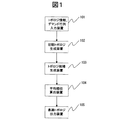
図1は、本発明の実施例の平均順位を用いた網トポロジ設計装置の概略構成を示すブロック図である。図1において、101はトポロジ情報・デマンド行列入力装置、102は初期トポロジ生成装置、103はトポロジ候補生成装置、104は平均順位算出装置、105は最適トポロジ出力装置である。
トポロジ情報・デマンド行列入力装置101により、エッジノードの位置、コアノードの設置可能位置、リンクの設置可能位置が入力される。
初期トポロジ生成装置102は、トポロジ情報・デマンド行列入力装置101により入力されたエッジノードの位置、コアノードの設置可能位置、リンクの設置可能位置に基づき初期トポロジを生成する。
トポロジ候補生成装置103は、初期トポロジ生成装置102により生成された初期トポロジに対して、幾つかのリンクとコアノードを追加して複数の候補トポロジを生成する。 平均順位算出装置104は、トポロジ候補生成装置103により生成された複数の候補トポロジ間の優劣を評価する。
最適トポロジ出力装置105は、平均順位算出装置104での評価結果に基づき最適トポロジの集合を出力する。
Hereinafter, embodiments of the present invention will be described in detail with reference to the drawings.
In all the drawings for explaining the embodiments, parts having the same functions are given the same reference numerals, and repeated explanation thereof is omitted.
FIG. 1 is a block diagram showing a schematic configuration of a network topology design apparatus using an average rank according to an embodiment of the present invention. In FIG. 1, 101 is a topology information / demand matrix input device, 102 is an initial topology generation device, 103 is a topology candidate generation device, 104 is an average rank calculation device, and 105 is an optimum topology output device.
The topology information / demand
The initial
The topology
The optimum
次に、本発明の実施例の平均順位を用いた網トポロジ設計方法について、詳細を説明する。なお、ここでは、例として、物理トポロジ設計を対象に検討を進めるが、論理パスを上位に設置することを想定し、物理トポロジ設計時に論理パスの設置も同時に行う(但し、リンク容量等の制約条件は考慮しない)。
しかし、本発明の網トポロジ設計法は、複数の評価尺度をどのように同時に考慮するかに主眼を置いており、制約条件については汎用性が高く、様々な制約条件が生じる運用開始後の論理トポロジ設計にも応用が可能である。
[評価尺度]
物理トポロジ設計を行う際に考慮すべき評価尺度について考える。設計対象として、特にバックボーンネットワークを考えると、物理トポロジには全エッジノード間の接続性と障害発生時にも接続性を維持できる冗長性が求められる。
そこで、ここでは、物理トポロジ設計時の制約条件として、(i)全エッジノード間の接続性、(ii)1リンク障容時にも全エッジノード間の接続性が迂回経路により維持されることの二つを考える。
Next, details of the network topology design method using the average rank of the embodiment of the present invention will be described. Here, as an example, the study will proceed with physical topology design as an example, but it is assumed that the logical path is installed at the upper level, and the logical path is also installed at the time of physical topology design (however, restrictions such as link capacity) Condition is not considered).
However, the network topology design method of the present invention focuses on how to consider a plurality of evaluation measures at the same time, and the constraint conditions are highly versatile. It can also be applied to topology design.
[Evaluation scale]
Consider the evaluation measures that should be considered when designing the physical topology. Considering a backbone network as a design object, the physical topology requires connectivity between all edge nodes and redundancy that can maintain connectivity even when a failure occurs.
Therefore, here, as constraints in the physical topology design, (i) connectivity between all edge nodes, and (ii) connectivity between all edge nodes is maintained by a detour path even when one link fails. Think about two things.
評価尺度としては様々なものが考えられるが、ここでは次の四つを例として考える。なお、i番目の評価尺度をViと表記する。
(1)総ノード数:
設置されたエッジノードとコアノードを合わせた総数であり、Neをエッジノード数、Ncを設置コアノード数とすると、1番目の評価尺度(V1)は、下記(1)式で表される。
V1=Ne+Nc ・・・・・・・・・・・・・・・・・ (1)
エッジノード数(Ne)は、全ての候補トポロジで同一なので、設置コアノード数(Nc)の差異がそのまま、1番目の評価尺度(V1)の差異となる。なお、1番目の評価尺度(V1)は小さい方が望ましい。
(2)総リンク距離:
設置されたリンクの距離の総和であり、dlをリンクlの距離、Εαを設置リンクの集合とすると、2番目の評価尺度(V2)は、下記(2)式で表される。2番目の評価尺度(V2)も小さい方が望ましい。
There are various evaluation scales, but here we consider the following four examples. The i-th evaluation scale is denoted as V i .
(1) Total number of nodes:
The total number of installed edge nodes and core nodes is the total, where Ne is the number of edge nodes and Nc is the number of installed core nodes, the first evaluation measure (V 1 ) is expressed by the following equation (1).
V 1 = Ne + Nc (1)
Since the number of edge nodes (Ne) is the same in all candidate topologies, the difference in the number of installed core nodes (Nc) becomes the difference in the first evaluation scale (V 1 ) as it is. The first evaluation scale (V 1 ) is preferably small.
(2) Total link distance:
The second evaluation scale (V 2 ) is expressed by the following expression (2), where d 1 is the sum of the distances of the installed links, d 1 is the distance of the

(3)パスの距離をトラヒック量で重み付けした総和:
伝送遅延の観点からはパス長が短いことが望ましく、下記(3)式に示す、パス長をパスのトラヒック量で重み付けした総和(ζ)を評価尺度として考える。但し、エッジノードsからエッジノードdに向かうトラヒックが流れるパスをPsd、パスPsdのトラヒック量をTsd、パスPsdが経由するリンクの集合をΦsd、パスPsdの長さを下記(4)式に示すDsdとする。
tlをリンクlの総トラヒック量とすると、ζはリンク距離dlとトラヒック量tlの積の総和に一致するため、総和(ζ)は下記(5)式となる。
よって、3番目の評価尺度(V3)は、下記(6)式で表される。3番目の評価尺度(V3)も小さい方が望ましい。
(3) Sum obtained by weighting the path distance by the traffic volume:
From the viewpoint of transmission delay, it is desirable that the path length is short, and a sum (ζ) obtained by weighting the path length by the traffic amount of the path shown in the following equation (3) is considered as an evaluation measure. The following, however, a path through which traffic directed from the edge node s to the edge node d P sd, path P sd traffic amount T sd, path P sd is a set of links through [Phi sd, the length of the path P sd It is set as Dsd shown to (4) Formula.
If t l is the total traffic amount of link l, ζ coincides with the sum of products of link distance d l and traffic amount t l , so the total sum (ζ) is expressed by the following equation (5).
Therefore, the third evaluation scale (V 3 ) is expressed by the following equation (6). It is desirable that the third evaluation scale (V 3 ) is also small.
(4)最大リンク負荷:
トラヒックが特定のリンクに集中した場合、ボトルネックリンクを通るパスの伝送品質は大きく悪化する。また、リンクの伝送帯域は光ファイバや波長といった離散的な単位で増設されるため、伝送資源を有効に活用するためにはリンク負荷の偏りを抑え、分散させることが望ましい。そこで、最大負荷リンクのトラヒック量を評価尺度として考えると、4番目の評価尺度(V4)は、下記(7)式で表される。4番目の評価尺度(V4)も小さい方が望ましい。
(4) Maximum link load:
When traffic is concentrated on a specific link, the transmission quality of the path through the bottleneck link is greatly deteriorated. Also, since the transmission bandwidth of the link is increased in discrete units such as optical fibers and wavelengths, it is desirable to suppress and disperse the link load in order to effectively use the transmission resources. Therefore, considering the traffic amount of the maximum load link as an evaluation measure, the fourth evaluation measure (V 4 ) is expressed by the following equation (7). It is desirable that the fourth evaluation scale (V 4 ) is also small.
[候補トポロジの作成]
与えられた設置可能位置に対して全く自由にリンクとコアノードを配置した場合、得られたトポロジ候補には制約条件を満たさないものも含まれる。そのため、最初に制約条件を満たす物理トポロジを初期解として作成し、初期解に対して更に任意のコアノードやリンクを追加配備することによって作成された物理トポロジの集合を解の侯補とする。
この結果、初期解を作成した段階で既に制約条件を満足しているので、任意の候補トポロジを採用することが可能となる。
初期トポロジで配置されたリンクを除いた残るリンク設置可能位置の数をzとする。任意の設置可能位置にリンクを配置した結果得られるトポロジの総数は2z個となる。
こうして作成された各トポロジにおいて、次数が3以上となったコアノード設置可能位置にはコアノードを配置するが、次数が2となったコアノード設置可能位置には交換機能が不要であるためコアノードを設置せず、2本の配置リンクを直結する。また、次数が1となるコアノード設置可能位置が存在するトポロジは不適切なトポロジであるため検討候補からは除く。
Create candidate topology
When links and core nodes are arranged freely at a given installable position, the obtained topology candidates include those that do not satisfy the constraint conditions. Therefore, a physical topology that satisfies the constraint conditions is first created as an initial solution, and a set of physical topologies created by additionally deploying arbitrary core nodes and links to the initial solution is used as a solution supplement.
As a result, since the constraint condition is already satisfied at the stage of creating the initial solution, it is possible to adopt an arbitrary candidate topology.
Let z be the number of remaining link installable positions excluding the links arranged in the initial topology. The total number of topologies obtained as a result of placing a link to any installable position is 2 z pieces.
In each topology created in this way, a core node is placed at the core node installable position where the order is 3 or higher, but no exchange function is required at the core node installable position where the order is 2, so the core node is placed. First, two placement links are directly connected. In addition, the topology in which the position where the core node where the degree is 1 is present is an inappropriate topology and is excluded from the candidates for examination.
次に、候補として作成した各トポロジに対して、与えられた交流トラヒック行列を用いて各エッジノード間に論理パスを設定する。ここでは、ノードsからノードdに流れるトラヒックに対しては、1本のパスPsdのみが設置され、パスPsdを要求トラヒック量Tsdの大きな順に構築法(一旦、配置したパスを変更しない)によりパスを設置する。
個々のパスの経路を決める際、下記(8)式に示すトラヒック量(ζ’)が最小となる経路を選択する。但し、該当パスを設置する時点のリンクlのトラヒック量をtlとする。パス設置時にリンク容量制約は考慮しない。全ての世パスを設置した結果、1本もパスから通らないリンクが存在するトポロジは、やはり不適切なトポロジであるため検討候補から除く。
Next, for each topology created as a candidate, a logical path is set between the edge nodes using a given AC traffic matrix. Here, for the traffic flowing from the node s to the node d, only one path P sd is installed, and the path P sd is constructed in descending order of the requested traffic amount T sd (once the arranged path is not changed). ) To set up a pass.
When determining the route of each path, the route that minimizes the traffic amount (ζ ′) shown in the following equation (8) is selected. However, the traffic amount of the
[平均順位によるトポロジ評価]
各候補トポロジiに対して、各評価尺度のΝの候補集合中の順位を算出する。全ての評価尺度は小さいほど望ましいので、順位は単に各評価尺度Vk,iを小さな順にソートすることで計算できる(k=1,2,3,4)。
こうしてトポロジiの各評価尺度Vk,iに対して得られた順位R(k,i)を用いて、下記(9)式により、トポロジiの平均順位(AR)を算出し、単純に平均順位(AR)の値が小さな侯補トポロジを優れたトポロジであると評価する。即ち、Nの全候補トポロジ中、平均順位(AR)の値が最小となったトポロジを最適な網トポロジであると判断する。
ARi={R(1,i)+R(2,i)+R(3,i)+R(4,i)}/4
・・・・・・・・・・・・・・・・・ (9)
通常、単位の異なる複数の評価尺度を単純に足し合わせて評価することはできない。しかし、各評価尺度を全侯補中の順位という相互比較が可能な同一の尺度に置き換えることにより、単純にそれらの平均値で最終的な優劣が評価できる。
平均順位法は、任意数Μ個の評価尺度を同時に考慮することができ、その場合、トポロジiの平均順位(AR)は下記(10)式となる。
評価値である平均順位の計算は非常に簡易である。各評価尺度の順位を求めるのにソート処理が必要であるが、MergeソートやQuickソートといったソートアルゴリズムを用いればO(ΝlogΝ)の処理量で済むことから、DEAと比較して遥かに短い時間で網トポロジ設計が可能である。
[Topology evaluation by average rank]
For each candidate topology i, the rank in the candidate set of wrinkles of each evaluation scale is calculated. Since all the evaluation scales are preferably as small as possible, the rank can be calculated simply by sorting the evaluation scales V k, i in ascending order (k = 1, 2, 3, 4).
Using the rank R (k, i) obtained for each evaluation measure V k, i of topology i in this way, the average rank (AR) of topology i is calculated according to the following equation (9). Complementary topologies with small rank (AR) values are evaluated as excellent topologies. That is, among all N candidate topologies, the topology having the smallest average rank (AR) is determined as the optimum network topology.
ARi = {R (1, i) + R (2, i) + R (3, i) + R (4, i)} / 4
.... (9)
Usually, it is not possible to simply add a plurality of evaluation scales having different units for evaluation. However, by substituting each evaluation scale with the same scale that can be compared with each other, the final superiority can be evaluated based on the average value.
In the average rank method, an arbitrary number of evaluation scales can be considered at the same time. In this case, the average rank (AR) of topology i is expressed by the following equation (10).
Calculation of the average rank, which is an evaluation value, is very simple. Sorting is required to determine the rank of each evaluation scale, but if a sort algorithm such as Merge sort or Quick sort is used, the processing amount of O (ΝlogΝ) is sufficient, so it takes much less time than DEA. Network topology design is possible.
[数値評価]
次に、具体的なネットワークモデルを用いて、平均順位法による網トポロジ設計を行った数値評価結果について述べる。
計算は全て、3.2GHzのCPU、1GBのメモリのパーソナルコンピュータ(PC)で行った。
[評価ネットワークモデル]
図2に、本実施例において、評価に用いたネットワークモデル(日本列島モデル)を示す。但し、黒丸がエッジノードを表し、点線で描かれた丸と線がコアノードとリンクの設置可能位置を表す。
また、図2には、各々のエッジノードkが収容する人口Ukを示す。エッジノードsからエッジノードdに流れるトラヒック量Tsdは、両端のエッジノードの人口の積に比例させ、下記(11)式で求める値とした。但し、Tはネットワーク全体のトラヒック量であり、ここでは、T=10Tbpsとした。
[Numeric evaluation]
Next, the numerical evaluation results obtained by designing the network topology by the average ranking method using a specific network model will be described.
All calculations were performed on a personal computer (PC) with a 3.2 GHz CPU and 1 GB memory.
[Evaluation network model]
FIG. 2 shows a network model (Japanese archipelago model) used for evaluation in this example. However, black circles represent edge nodes, and circles and lines drawn with dotted lines represent positions where core nodes and links can be installed.
FIG. 2 shows the population U k accommodated by each edge node k. The traffic amount T sd flowing from the edge node s to the edge node d is proportional to the product of the population of the edge nodes at both ends, and is a value obtained by the following equation (11). However, T is the traffic amount of the entire network, and here, T = 10 Tbps.
1リンク障害に対して迂回路を確保でき、全エッジノード間の接続性を確保できる初期トポロジとしてループ型トポロジを考え、図2の実線で示すリンク設置可能位置には必ずリンクを配置した。
ループが経由するコアノード設置可能位置の次数は2となり交換機能が不要であることから、これら設置可能位置にコアノードを配置する必要はない。
初期トポロジで採用されたリンクを除くと、17本のリンク設置可能位置が残るため217個の物理トポロジを構成可能であるが、次数が1となるコアノードや未使用リンクが存在するトポロジを候補から除外した結果、83,868個の侯補トポロジが得られた。なお、これらの候補トポロジを得るのに要した計算時間は75秒程度であった。
Considering a loop topology as an initial topology that can secure a detour for one link failure and ensure connectivity between all edge nodes, a link is always placed at a link installable position indicated by a solid line in FIG.
Since the order of the core node installable positions through which the loop passes is 2 and the exchange function is unnecessary, there is no need to arrange the core nodes at these installable positions.
Except for the links used in the initial topology, 17 link installation positions remain, so 2 17 physical topologies can be configured, but the topologies with core nodes or unused links of
[平均順位法の適用結果]
平均順位(AR)の算出に要する計算量は僅かであり、83,868個の全ての侯補トポロジを対象に平均順位(AR)を算出しても要した時間は1秒未満であった。
平均順位(AR)が小さなトポロジほど望ましいトポロジであるため、候補トポロジの最終評価順位は平均順位(AR)の小さな順となる。
図3は、83,868個の候補トポロジを対象に、前述の(5)式より算出した平均順位(AR)を最終評価の順にプロットしたグラフである。
83,868個の候補トポロジにおける、平均順位(AR)の最小値、最大値、平均は各々、3813.25、75295.25、39915.0であった。
4つの評価尺度のいくつかは相反するため、全ての評価尺度が非常に優れた候補トポロジや、反対に全ての評価尺度が非常に悪い候補トポロジは存在しない。そのため、平均順位(AR)の最小値は1より大きく、平均順位(AR)の最大値は候補トポロジ数83,868より小さな値となっている。
[Results of applying the average ranking method]
The amount of calculation required to calculate the average rank (AR) is very small, and even if the average rank (AR) is calculated for all 83,868 complemented topologies, the time required is less than 1 second.
Since a topology with a smaller average rank (AR) is a desirable topology, the final evaluation rank of candidate topologies is in the order of smaller average rank (AR).
FIG. 3 is a graph in which the average rank (AR) calculated from the above-described equation (5) is plotted in the order of final evaluation for 83,868 candidate topologies.
The minimum value, maximum value, and average of the average rank (AR) in 83,868 candidate topologies were 3813.25, 75295.25, and 39915.0, respectively.
Since some of the four evaluation measures are contradictory, there is no candidate topology in which all evaluation measures are very good, and conversely, all candidate evaluation measures are very bad. Therefore, the minimum value of the average rank (AR) is larger than 1, and the maximum value of the average rank (AR) is smaller than the number of candidate topologies 83,868.
大多数の候補トポロジの平均順位(AR)は20,000〜60,000の範囲に存在し、平均順位(AR)が最小値(3613.25)に近いトポロジは少数に限定されることがわかる。
このことは、これら平均順位(AR)が小さな少数のトポロジのみに選択候補を絞ることにより、少数の優れた網トポロジを選択できることを意味する。
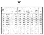
図4は、図3に示すグラフの平均順位(AR)が小さな上位10位のトポロジについて、平均順位(AR)、4つの評価尺度の値と、それらの全候補トポロジ中の順位をまとめた表である。また、これら上位10のトポロジを図5に示す。4つの全ての評価尺度が良好なバランスのいい侯補トポロジが、平均順位法では高く評価されることがわかる。
It can be seen that the average rank (AR) of the majority of candidate topologies is in the range of 20,000-60,000, and the topologies whose average rank (AR) is close to the minimum value (361.25) are limited to a small number. .
This means that a small number of excellent network topologies can be selected by narrowing the selection candidates to only a small number of topologies having a small average rank (AR).
FIG. 4 is a table that summarizes the average rank (AR), the values of the four evaluation measures, and ranks in all the candidate topologies for the top ten top-ranked topologies with the small average rank (AR) in the graph shown in FIG. It is. These top 10 topologies are shown in FIG. It can be seen that a well-balanced complement topology with all four rating scales being highly appreciated by the average rank method.
図6は、平均順位(AR)の小さい最終評価順位の高い候補トポロジの順に、4つの評価尺度を各々プロットしたグラフである。1つの点が1つの候補トポロジに対応する。但し、平均順位(AR)が10位以内の侯補トポロジについては大きな点でプロットしている。
全ての評価尺度が良好な候補トポロジが、平均順位法では上位に評価されることが確認できる。また、V1、V2、およびV4の評価尺度が極めて良好な物理トポロジの平均順位(AR)は大きく、平均順位法での評価は低いことが確認できる。
このことは、単一の評価尺度のみを考慮して綱トポロジ設計を行った場合、他の評価尺度が悪化することを意味し、平均順位法の有効性が確認できる。
以上説明したように、本実施例によれば、コアノードやリンクが設置可能な場所と、エッジノード、エッジノード間の交流トラヒック行列が与えられているときに、複数の評価尺度を考慮した上で最適な綱トポロジを、平均順位法により評価して求めることができる。
以上、本発明者によってなされた発明を、前記実施例に基づき具体的に説明したが、本発明は、前記実施例に限定されるものではなく、その要旨を逸脱しない範囲において種々変更可能であることは勿論である。
FIG. 6 is a graph in which four evaluation measures are respectively plotted in order of candidate topologies having a high average evaluation rank (AR) and a high final evaluation rank. One point corresponds to one candidate topology. However, the compensated topology having an average rank (AR) of 10 or less is plotted with a large point.
It can be confirmed that candidate topologies having good evaluation scales are evaluated highly in the average ranking method. Further, it can be confirmed that the average rank (AR) of the physical topology having very good evaluation scales of V 1 , V 2 , and V 4 is large and the evaluation by the average rank method is low.
This means that when a rope topology design is performed considering only a single evaluation scale, the other evaluation scales deteriorate, and the effectiveness of the average ranking method can be confirmed.
As described above, according to the present embodiment, when a location where a core node or link can be installed and an AC traffic matrix between edge nodes and edge nodes are given, a plurality of evaluation measures are taken into consideration. The optimal rope topology can be evaluated and determined by the average rank method.
As mentioned above, the invention made by the present inventor has been specifically described based on the above embodiments. However, the present invention is not limited to the above embodiments, and various modifications can be made without departing from the scope of the invention. Of course.
101 トポロジ情報・デマンド行列入力装置
102 初期トポロジ生成装置
103 トポロジ候補生成装置
104 平均順位算出装置
105 最適トポロジ出力装置
101 topology information / demand
Claims (3)
各々のトポロジ候補に対して、同時に考慮する評価尺度ごとに全候補中の順位を計算し、
評価尺度ごとに得られた順位の平均値を計算し、平均順位で候補間の優劣を判断することを特徴とする網トポロジ設計方法。 When a set of edge nodes that accommodate users, a set of candidate core nodes that have only a relay function, and a set of link candidates that connect them, are used while simultaneously considering multiple evaluation measures A network topology design method for selecting a set of core nodes and links,
For each topology candidate, calculate the rank among all candidates for each evaluation measure considered simultaneously,
A network topology design method, comprising: calculating an average value of ranks obtained for each evaluation scale, and determining superiority or inferiority among candidates based on the average rank.
エッジノードの位置、コアノードの設置可能位置、リンクの設置可能位置が入力されるトポロジ情報・デマンド行列入力装置と、
前記トポロジ情報・デマンド行列入力装置により入力されたエッジノードの位置、コアノードの設置可能位置、リンクの設置可能位置に基づき、初期トポロジを生成する初期トポロジ生成装置と、
前記初期トポロジ生成装置により生成された初期トポロジに対して、いくつかのリンクとコアノードを追加して複数の候補トポロジを生成するトポロジ候補生成装置と、
前記トポロジ候補生成装置により生成された複数の候補トポロジに対して、同時に考慮する評価尺度ごとに全候補中の順位を計算し、各評価尺度ごとに得られた順位の平均値を計算し、平均順位で候補間の優劣を判断する平均順位算出装置と、
前記平均順位算出装置での評価結果に基づき最適トポロジの集合を出力する最適トポロジ出力装置とを有することを特徴とする網トポロジ設計装置。 When a set of edge nodes that accommodate users, a set of candidate core nodes that have only a relay function, and a set of link candidates that connect them, are used while simultaneously considering multiple evaluation measures A network topology design device for selecting a set of core nodes and links,
Topology information / demand matrix input device for inputting the position of the edge node, the installable position of the core node, and the installable position of the link;
An initial topology generation device for generating an initial topology based on the position of the edge node, the installable position of the core node, and the installable position of the link, which are input by the topology information / demand matrix input device;
A topology candidate generation device that generates a plurality of candidate topologies by adding several links and core nodes to the initial topology generated by the initial topology generation device;
For a plurality of candidate topologies generated by the topology candidate generation device, the rank among all candidates is calculated for each evaluation scale to be considered simultaneously, the average value of the ranks obtained for each evaluation scale is calculated, and the average An average rank calculation device that judges superiority or inferiority among candidates by rank;
A network topology design device, comprising: an optimum topology output device that outputs a set of optimum topologies based on an evaluation result in the average rank calculation device.
Priority Applications (1)
| Application Number | Priority Date | Filing Date | Title |
|---|---|---|---|
| JP2006162976A JP2007336021A (en) | 2006-06-13 | 2006-06-13 | Network topology design method and network topology design apparatus |
Applications Claiming Priority (1)
| Application Number | Priority Date | Filing Date | Title |
|---|---|---|---|
| JP2006162976A JP2007336021A (en) | 2006-06-13 | 2006-06-13 | Network topology design method and network topology design apparatus |
Publications (1)
| Publication Number | Publication Date |
|---|---|
| JP2007336021A true JP2007336021A (en) | 2007-12-27 |
Family
ID=38935102
Family Applications (1)
| Application Number | Title | Priority Date | Filing Date |
|---|---|---|---|
| JP2006162976A Pending JP2007336021A (en) | 2006-06-13 | 2006-06-13 | Network topology design method and network topology design apparatus |
Country Status (1)
| Country | Link |
|---|---|
| JP (1) | JP2007336021A (en) |
Cited By (5)
| Publication number | Priority date | Publication date | Assignee | Title |
|---|---|---|---|---|
| JP2009118201A (en) * | 2007-11-07 | 2009-05-28 | Nippon Telegr & Teleph Corp <Ntt> | Network topology link capacity design processing method, system and program |
| JP2010240209A (en) * | 2009-04-07 | 2010-10-28 | Sumitomo Rubber Ind Ltd | Design variable for golf club shaft, and method of manufacture the same |
| CN113537722A (en) * | 2021-06-23 | 2021-10-22 | 西安交通大学 | Scheduling planning method and application |
| CN114116599A (en) * | 2021-12-17 | 2022-03-01 | 广东工业大学 | Three-dimensional network-on-chip topological structure design method |
| CN114531701A (en) * | 2022-02-25 | 2022-05-24 | 合肥工业大学 | Collaborative optimization method for data transmission reliability and topological robustness of heterogeneous network in extra-high voltage direct current control protection system |
Citations (6)
| Publication number | Priority date | Publication date | Assignee | Title |
|---|---|---|---|---|
| JPH05290023A (en) * | 1992-04-15 | 1993-11-05 | Fujitsu Ltd | System for optimumly designing communication network |
| JP2002278998A (en) * | 2001-03-19 | 2002-09-27 | Kawasaki Heavy Ind Ltd | Processing method for optimized design having a plurality of evaluation references |
| JP2002334215A (en) * | 2001-05-09 | 2002-11-22 | Kao Corp | Insurance reconsideration proposal supporting method |
| JP2003058588A (en) * | 2000-10-03 | 2003-02-28 | Ntt Infranet Co Ltd | Method and system for setting and managing pipe line for communication, recording medium recorded with pipe line for communication setting and management program and method and system for managing pipe line for communication maintenance, recording medium recorded with pipe line for communication maintenance management program and system for managing pipe line for communication |
| JP2003179970A (en) * | 2001-12-11 | 2003-06-27 | Brother Ind Ltd | Radio communication device |
| JP2005025275A (en) * | 2003-06-30 | 2005-01-27 | Ntt Power & Building Facilities Inc | Real estate asset valuation system |
-
2006
- 2006-06-13 JP JP2006162976A patent/JP2007336021A/en active Pending
Patent Citations (6)
| Publication number | Priority date | Publication date | Assignee | Title |
|---|---|---|---|---|
| JPH05290023A (en) * | 1992-04-15 | 1993-11-05 | Fujitsu Ltd | System for optimumly designing communication network |
| JP2003058588A (en) * | 2000-10-03 | 2003-02-28 | Ntt Infranet Co Ltd | Method and system for setting and managing pipe line for communication, recording medium recorded with pipe line for communication setting and management program and method and system for managing pipe line for communication maintenance, recording medium recorded with pipe line for communication maintenance management program and system for managing pipe line for communication |
| JP2002278998A (en) * | 2001-03-19 | 2002-09-27 | Kawasaki Heavy Ind Ltd | Processing method for optimized design having a plurality of evaluation references |
| JP2002334215A (en) * | 2001-05-09 | 2002-11-22 | Kao Corp | Insurance reconsideration proposal supporting method |
| JP2003179970A (en) * | 2001-12-11 | 2003-06-27 | Brother Ind Ltd | Radio communication device |
| JP2005025275A (en) * | 2003-06-30 | 2005-01-27 | Ntt Power & Building Facilities Inc | Real estate asset valuation system |
Non-Patent Citations (1)
| Title |
|---|
| 上山憲昭: "複数の評価尺度を考慮した網トポロジ設計", 電子情報通信学会技術研究報告 IN2006-31, vol. 106, no. 118, JPN6008032097, 15 June 2006 (2006-06-15), JP, pages 85 - 90, ISSN: 0001076554 * |
Cited By (7)
| Publication number | Priority date | Publication date | Assignee | Title |
|---|---|---|---|---|
| JP2009118201A (en) * | 2007-11-07 | 2009-05-28 | Nippon Telegr & Teleph Corp <Ntt> | Network topology link capacity design processing method, system and program |
| JP2010240209A (en) * | 2009-04-07 | 2010-10-28 | Sumitomo Rubber Ind Ltd | Design variable for golf club shaft, and method of manufacture the same |
| CN113537722A (en) * | 2021-06-23 | 2021-10-22 | 西安交通大学 | Scheduling planning method and application |
| CN113537722B (en) * | 2021-06-23 | 2023-08-01 | 西安交通大学 | Scheduling planning method and application |
| CN114116599A (en) * | 2021-12-17 | 2022-03-01 | 广东工业大学 | Three-dimensional network-on-chip topological structure design method |
| CN114531701A (en) * | 2022-02-25 | 2022-05-24 | 合肥工业大学 | Collaborative optimization method for data transmission reliability and topological robustness of heterogeneous network in extra-high voltage direct current control protection system |
| CN114531701B (en) * | 2022-02-25 | 2023-08-11 | 合肥工业大学 | Cooperative optimization method for heterogeneous network in extra-high voltage direct current control protection system |
Similar Documents
| Publication | Publication Date | Title |
|---|---|---|
| US8010694B2 (en) | Network performance and reliability evaluation taking into account multiple traffic matrices | |
| US8443079B2 (en) | Mixed integer programming model for minimizing leased access network costs | |
| US20020097680A1 (en) | Apparatus and method for spare capacity allocation | |
| US20130028074A1 (en) | Method and apparatus for protecting a communication network against failure | |
| Sun et al. | Optimal provisioning for virtual network request in cloud-based data centers | |
| Botero et al. | A novel paths algebra-based strategy to flexibly solve the link mapping stage of VNE problems | |
| JP4909060B2 (en) | Network topology design method and design system using AHP | |
| JP2007336021A (en) | Network topology design method and network topology design apparatus | |
| Kashyap et al. | Routing and traffic engineering in hybrid RF/FSO networks | |
| Masri et al. | Metaheuristics for solving the biobjective single‐path multicommodity communication flow problem | |
| JP2010011285A (en) | Network topology candidate listing method and apparatus, and network topology designing method, system, and program | |
| Fortz et al. | Optimal design of switched Ethernet networks implementing the Multiple Spanning Tree Protocol | |
| JP5553312B2 (en) | Optimal route selection method, optimum route selection program, and optimum route selection device | |
| Shahriar | Survivable virtual network embedding in transport networks | |
| JP4279291B2 (en) | Network topology design device | |
| Bley et al. | Robustness in communication networks: scenarios and mathematical approaches | |
| JP6637911B2 (en) | Network design apparatus, network design method, and network design processing program | |
| Gomes et al. | Two heuristics for calculating a shared risk link group disjoint set of paths of min-sum cost | |
| Chen et al. | On the benefits of multipath routing for distributed data-intensive applications with high bandwidth requirements and multidomain reach | |
| Bauknecht et al. | Reduction of Delay Overfulfillment in IP-over-DWDM Transport Networks | |
| Abramov et al. | A new teletraffic approach for network planning and evolution prediction | |
| CN102142972B (en) | Networking method and networking device of IP (internet protocol) network | |
| Duelli et al. | Greedy design of resilient multi-layer networks | |
| Chen et al. | QoS-constrained multi-path routing for high-end network applications | |
| JP2010206581A (en) | Topology generation system, method, network topology design system, and program |
Legal Events
| Date | Code | Title | Description |
|---|---|---|---|
| A977 | Report on retrieval |
Free format text: JAPANESE INTERMEDIATE CODE: A971007 Effective date: 20080609 |
|
| A131 | Notification of reasons for refusal |
Free format text: JAPANESE INTERMEDIATE CODE: A131 Effective date: 20080701 |
|
| A521 | Request for written amendment filed |
Free format text: JAPANESE INTERMEDIATE CODE: A523 Effective date: 20080901 |
|
| A131 | Notification of reasons for refusal |
Free format text: JAPANESE INTERMEDIATE CODE: A131 Effective date: 20081216 |
|
| A02 | Decision of refusal |
Free format text: JAPANESE INTERMEDIATE CODE: A02 Effective date: 20090602 |