JP2007325724A - Management system for cleaning and disinfection of endoscope - Google Patents
Management system for cleaning and disinfection of endoscope Download PDFInfo
- Publication number
- JP2007325724A JP2007325724A JP2006158811A JP2006158811A JP2007325724A JP 2007325724 A JP2007325724 A JP 2007325724A JP 2006158811 A JP2006158811 A JP 2006158811A JP 2006158811 A JP2006158811 A JP 2006158811A JP 2007325724 A JP2007325724 A JP 2007325724A
- Authority
- JP
- Japan
- Prior art keywords
- endoscope
- cleaning
- disinfecting
- time
- end time
- Prior art date
- Legal status (The legal status is an assumption and is not a legal conclusion. Google has not performed a legal analysis and makes no representation as to the accuracy of the status listed.)
- Withdrawn
Links
Images


Classifications
-
- A—HUMAN NECESSITIES
- A61—MEDICAL OR VETERINARY SCIENCE; HYGIENE
- A61B—DIAGNOSIS; SURGERY; IDENTIFICATION
- A61B1/00—Instruments for performing medical examinations of the interior of cavities or tubes of the body by visual or photographical inspection, e.g. endoscopes; Illuminating arrangements therefor
- A61B1/00142—Instruments for performing medical examinations of the interior of cavities or tubes of the body by visual or photographical inspection, e.g. endoscopes; Illuminating arrangements therefor with means for preventing contamination, e.g. by using a sanitary sheath
- A61B1/00144—Hygienic packaging
-
- A—HUMAN NECESSITIES
- A61—MEDICAL OR VETERINARY SCIENCE; HYGIENE
- A61L—METHODS OR APPARATUS FOR STERILISING MATERIALS OR OBJECTS IN GENERAL; DISINFECTION, STERILISATION OR DEODORISATION OF AIR; CHEMICAL ASPECTS OF BANDAGES, DRESSINGS, ABSORBENT PADS OR SURGICAL ARTICLES; MATERIALS FOR BANDAGES, DRESSINGS, ABSORBENT PADS OR SURGICAL ARTICLES
- A61L2/00—Methods or apparatus for disinfecting or sterilising materials or objects other than foodstuffs or contact lenses; Accessories therefor
- A61L2/16—Methods or apparatus for disinfecting or sterilising materials or objects other than foodstuffs or contact lenses; Accessories therefor using chemical substances
- A61L2/18—Liquid substances or solutions comprising solids or dissolved gases
-
- A—HUMAN NECESSITIES
- A61—MEDICAL OR VETERINARY SCIENCE; HYGIENE
- A61B—DIAGNOSIS; SURGERY; IDENTIFICATION
- A61B1/00—Instruments for performing medical examinations of the interior of cavities or tubes of the body by visual or photographical inspection, e.g. endoscopes; Illuminating arrangements therefor
- A61B1/00002—Operational features of endoscopes
- A61B1/00004—Operational features of endoscopes characterised by electronic signal processing
- A61B1/00006—Operational features of endoscopes characterised by electronic signal processing of control signals
-
- A—HUMAN NECESSITIES
- A61—MEDICAL OR VETERINARY SCIENCE; HYGIENE
- A61B—DIAGNOSIS; SURGERY; IDENTIFICATION
- A61B1/00—Instruments for performing medical examinations of the interior of cavities or tubes of the body by visual or photographical inspection, e.g. endoscopes; Illuminating arrangements therefor
- A61B1/00002—Operational features of endoscopes
- A61B1/00043—Operational features of endoscopes provided with output arrangements
- A61B1/00055—Operational features of endoscopes provided with output arrangements for alerting the user
-
- A—HUMAN NECESSITIES
- A61—MEDICAL OR VETERINARY SCIENCE; HYGIENE
- A61B—DIAGNOSIS; SURGERY; IDENTIFICATION
- A61B1/00—Instruments for performing medical examinations of the interior of cavities or tubes of the body by visual or photographical inspection, e.g. endoscopes; Illuminating arrangements therefor
- A61B1/00002—Operational features of endoscopes
- A61B1/00059—Operational features of endoscopes provided with identification means for the endoscope
-
- A—HUMAN NECESSITIES
- A61—MEDICAL OR VETERINARY SCIENCE; HYGIENE
- A61B—DIAGNOSIS; SURGERY; IDENTIFICATION
- A61B1/00—Instruments for performing medical examinations of the interior of cavities or tubes of the body by visual or photographical inspection, e.g. endoscopes; Illuminating arrangements therefor
- A61B1/00064—Constructional details of the endoscope body
- A61B1/00105—Constructional details of the endoscope body characterised by modular construction
-
- A—HUMAN NECESSITIES
- A61—MEDICAL OR VETERINARY SCIENCE; HYGIENE
- A61B—DIAGNOSIS; SURGERY; IDENTIFICATION
- A61B1/00—Instruments for performing medical examinations of the interior of cavities or tubes of the body by visual or photographical inspection, e.g. endoscopes; Illuminating arrangements therefor
- A61B1/00112—Connection or coupling means
- A61B1/00119—Tubes or pipes in or with an endoscope
-
- A—HUMAN NECESSITIES
- A61—MEDICAL OR VETERINARY SCIENCE; HYGIENE
- A61B—DIAGNOSIS; SURGERY; IDENTIFICATION
- A61B1/00—Instruments for performing medical examinations of the interior of cavities or tubes of the body by visual or photographical inspection, e.g. endoscopes; Illuminating arrangements therefor
- A61B1/04—Instruments for performing medical examinations of the interior of cavities or tubes of the body by visual or photographical inspection, e.g. endoscopes; Illuminating arrangements therefor combined with photographic or television appliances
- A61B1/042—Instruments for performing medical examinations of the interior of cavities or tubes of the body by visual or photographical inspection, e.g. endoscopes; Illuminating arrangements therefor combined with photographic or television appliances characterised by a proximal camera, e.g. a CCD camera
-
- A—HUMAN NECESSITIES
- A61—MEDICAL OR VETERINARY SCIENCE; HYGIENE
- A61B—DIAGNOSIS; SURGERY; IDENTIFICATION
- A61B1/00—Instruments for performing medical examinations of the interior of cavities or tubes of the body by visual or photographical inspection, e.g. endoscopes; Illuminating arrangements therefor
- A61B1/12—Instruments for performing medical examinations of the interior of cavities or tubes of the body by visual or photographical inspection, e.g. endoscopes; Illuminating arrangements therefor with cooling or rinsing arrangements
- A61B1/121—Instruments for performing medical examinations of the interior of cavities or tubes of the body by visual or photographical inspection, e.g. endoscopes; Illuminating arrangements therefor with cooling or rinsing arrangements provided with means for cleaning post-use
- A61B1/122—Instruments for performing medical examinations of the interior of cavities or tubes of the body by visual or photographical inspection, e.g. endoscopes; Illuminating arrangements therefor with cooling or rinsing arrangements provided with means for cleaning post-use using cleaning tools, e.g. brushes
-
- A—HUMAN NECESSITIES
- A61—MEDICAL OR VETERINARY SCIENCE; HYGIENE
- A61B—DIAGNOSIS; SURGERY; IDENTIFICATION
- A61B1/00—Instruments for performing medical examinations of the interior of cavities or tubes of the body by visual or photographical inspection, e.g. endoscopes; Illuminating arrangements therefor
- A61B1/12—Instruments for performing medical examinations of the interior of cavities or tubes of the body by visual or photographical inspection, e.g. endoscopes; Illuminating arrangements therefor with cooling or rinsing arrangements
- A61B1/121—Instruments for performing medical examinations of the interior of cavities or tubes of the body by visual or photographical inspection, e.g. endoscopes; Illuminating arrangements therefor with cooling or rinsing arrangements provided with means for cleaning post-use
- A61B1/123—Instruments for performing medical examinations of the interior of cavities or tubes of the body by visual or photographical inspection, e.g. endoscopes; Illuminating arrangements therefor with cooling or rinsing arrangements provided with means for cleaning post-use using washing machines
-
- A—HUMAN NECESSITIES
- A61—MEDICAL OR VETERINARY SCIENCE; HYGIENE
- A61L—METHODS OR APPARATUS FOR STERILISING MATERIALS OR OBJECTS IN GENERAL; DISINFECTION, STERILISATION OR DEODORISATION OF AIR; CHEMICAL ASPECTS OF BANDAGES, DRESSINGS, ABSORBENT PADS OR SURGICAL ARTICLES; MATERIALS FOR BANDAGES, DRESSINGS, ABSORBENT PADS OR SURGICAL ARTICLES
- A61L2/00—Methods or apparatus for disinfecting or sterilising materials or objects other than foodstuffs or contact lenses; Accessories therefor
-
- G—PHYSICS
- G16—INFORMATION AND COMMUNICATION TECHNOLOGY [ICT] SPECIALLY ADAPTED FOR SPECIFIC APPLICATION FIELDS
- G16H—HEALTHCARE INFORMATICS, i.e. INFORMATION AND COMMUNICATION TECHNOLOGY [ICT] SPECIALLY ADAPTED FOR THE HANDLING OR PROCESSING OF MEDICAL OR HEALTHCARE DATA
- G16H40/00—ICT specially adapted for the management or administration of healthcare resources or facilities; ICT specially adapted for the management or operation of medical equipment or devices
- G16H40/40—ICT specially adapted for the management or administration of healthcare resources or facilities; ICT specially adapted for the management or operation of medical equipment or devices for the management of medical equipment or devices, e.g. scheduling maintenance or upgrades
-
- A—HUMAN NECESSITIES
- A61—MEDICAL OR VETERINARY SCIENCE; HYGIENE
- A61B—DIAGNOSIS; SURGERY; IDENTIFICATION
- A61B1/00—Instruments for performing medical examinations of the interior of cavities or tubes of the body by visual or photographical inspection, e.g. endoscopes; Illuminating arrangements therefor
- A61B1/00112—Connection or coupling means
- A61B1/00121—Connectors, fasteners and adapters, e.g. on the endoscope handle
- A61B1/00124—Connectors, fasteners and adapters, e.g. on the endoscope handle electrical, e.g. electrical plug-and-socket connection
-
- A—HUMAN NECESSITIES
- A61—MEDICAL OR VETERINARY SCIENCE; HYGIENE
- A61B—DIAGNOSIS; SURGERY; IDENTIFICATION
- A61B1/00—Instruments for performing medical examinations of the interior of cavities or tubes of the body by visual or photographical inspection, e.g. endoscopes; Illuminating arrangements therefor
- A61B1/00112—Connection or coupling means
- A61B1/00121—Connectors, fasteners and adapters, e.g. on the endoscope handle
- A61B1/00126—Connectors, fasteners and adapters, e.g. on the endoscope handle optical, e.g. for light supply cables
-
- A—HUMAN NECESSITIES
- A61—MEDICAL OR VETERINARY SCIENCE; HYGIENE
- A61B—DIAGNOSIS; SURGERY; IDENTIFICATION
- A61B1/00—Instruments for performing medical examinations of the interior of cavities or tubes of the body by visual or photographical inspection, e.g. endoscopes; Illuminating arrangements therefor
- A61B1/04—Instruments for performing medical examinations of the interior of cavities or tubes of the body by visual or photographical inspection, e.g. endoscopes; Illuminating arrangements therefor combined with photographic or television appliances
- A61B1/05—Instruments for performing medical examinations of the interior of cavities or tubes of the body by visual or photographical inspection, e.g. endoscopes; Illuminating arrangements therefor combined with photographic or television appliances characterised by the image sensor, e.g. camera, being in the distal end portion
-
- A—HUMAN NECESSITIES
- A61—MEDICAL OR VETERINARY SCIENCE; HYGIENE
- A61B—DIAGNOSIS; SURGERY; IDENTIFICATION
- A61B90/00—Instruments, implements or accessories specially adapted for surgery or diagnosis and not covered by any of the groups A61B1/00 - A61B50/00, e.g. for luxation treatment or for protecting wound edges
- A61B90/70—Cleaning devices specially adapted for surgical instruments
- A61B2090/701—Cleaning devices specially adapted for surgical instruments for flexible tubular instruments, e.g. endoscopes
-
- A—HUMAN NECESSITIES
- A61—MEDICAL OR VETERINARY SCIENCE; HYGIENE
- A61B—DIAGNOSIS; SURGERY; IDENTIFICATION
- A61B2560/00—Constructional details of operational features of apparatus; Accessories for medical measuring apparatus
- A61B2560/02—Operational features
- A61B2560/0266—Operational features for monitoring or limiting apparatus function
- A61B2560/0276—Determining malfunction
Landscapes
- Health & Medical Sciences (AREA)
- Life Sciences & Earth Sciences (AREA)
- Surgery (AREA)
- Engineering & Computer Science (AREA)
- Biomedical Technology (AREA)
- Public Health (AREA)
- General Health & Medical Sciences (AREA)
- Veterinary Medicine (AREA)
- Animal Behavior & Ethology (AREA)
- Medical Informatics (AREA)
- Radiology & Medical Imaging (AREA)
- Heart & Thoracic Surgery (AREA)
- Physics & Mathematics (AREA)
- Molecular Biology (AREA)
- Pathology (AREA)
- Optics & Photonics (AREA)
- Nuclear Medicine, Radiotherapy & Molecular Imaging (AREA)
- Biophysics (AREA)
- Business, Economics & Management (AREA)
- General Business, Economics & Management (AREA)
- Epidemiology (AREA)
- Signal Processing (AREA)
- Primary Health Care (AREA)
- Chemical & Material Sciences (AREA)
- Chemical Kinetics & Catalysis (AREA)
- General Chemical & Material Sciences (AREA)
- Endoscopes (AREA)
- Instruments For Viewing The Inside Of Hollow Bodies (AREA)
Abstract
Description
本発明は、使用済みの内視鏡の洗滌、及び消毒管理する内視鏡洗浄消毒管理システムに関する。 The present invention relates to an endoscope cleaning / disinfecting management system for cleaning and disinfecting a used endoscope.
体腔内の検査や治療の目的に使用される内視鏡は、体腔内に挿入される挿入部の外表面だけでなく、挿入部内に設けられている鉗子チャンネルを兼ねる吸引管路等の各内視鏡管路(チャンネル)内に体液、汚物などが付着する。そのため、内視鏡は、使用後、挿入部の外表面、及び内視鏡管路を充分に洗浄、消毒する必要がある。 Endoscopes used for the purpose of inspection and treatment in body cavities are not only the outer surface of the insertion part inserted into the body cavity, but also each of the internal pipes such as suction lines that also serve as forceps channels provided in the insertion part. Body fluid, filth, etc. adhere to the endoscope channel (channel). Therefore, it is necessary for the endoscope to sufficiently clean and disinfect the outer surface of the insertion portion and the endoscope channel after use.
例えば、特開平11−76145号公報は、内視鏡を洗浄するための内視鏡洗浄器を開示している。この内視鏡洗浄器は、内視鏡管路の洗浄するために、洗浄ブラシを内視鏡管路の奥部に向かって導入するためのブラシ挿入管を備えている。
しかしながら、内視鏡は、使用後、所定時間経過すると、特に内視鏡管路に付着した体液、汚物の除去が難しくなるために、使用後の所定時間に応じた洗浄を行う必要があるが、従来は、内視鏡の使用後の所定時間経過に基づいた体液、汚物の除去が行われておらず、効率的な内視鏡洗浄消毒処理ができないといった問題がある。 However, the endoscope needs to be cleaned according to the predetermined time after use because it becomes difficult to remove body fluid and dirt attached to the endoscope channel after a predetermined time after use. Conventionally, there is a problem that body fluids and filth are not removed based on the passage of a predetermined time after the use of the endoscope, and an efficient endoscope cleaning and disinfecting process cannot be performed.
本発明は、上記事情に鑑みてなされたものであり、内視鏡の使用後の所定時間経過に基づいた内視鏡洗浄消毒処理を行うことのできる内視鏡洗浄消毒管理システムを提供することを目的としている。 The present invention has been made in view of the above circumstances, and provides an endoscope cleaning / disinfecting management system capable of performing endoscope cleaning / disinfecting processing based on the passage of a predetermined time after use of an endoscope. It is an object.
本発明の内視鏡洗浄消毒管理システムは、管腔内に挿入する挿入部を備えた内視鏡を用い、内視鏡検査を行う内視鏡検査装置と、
前記内視鏡を、少なくとも洗浄及び消毒する内視鏡洗浄消毒装置と、
前記内視鏡検査装置における前記内視鏡検査の終了時間を記憶する第1の時間記憶手段と
を備え、
前記内視鏡洗浄消毒装置は、前記第1の時間記憶手段が記憶した前記内視鏡検査の終了時間に基づき、前記内視鏡の、少なくとも洗浄及び消毒工程を制御する洗浄及び消毒工程制御手段を
有して構成される。
An endoscope cleaning / disinfecting management system according to the present invention uses an endoscope having an insertion portion to be inserted into a lumen, and performs an endoscopic inspection apparatus for performing an endoscopic inspection,
An endoscope cleaning / disinfecting apparatus for cleaning and disinfecting the endoscope at least;
First time storage means for storing an end time of the endoscopy in the endoscopy device,
The endoscope cleaning and disinfecting apparatus is a cleaning and disinfecting process control unit that controls at least a cleaning and disinfecting process of the endoscope based on an end time of the endoscopy stored in the first time storage unit. It is configured with.
本発明によれば、内視鏡の使用後の所定時間経過に基づいた内視鏡洗浄消毒処理を行うことができるという効果がある。 According to the present invention, there is an effect that it is possible to perform endoscope cleaning / disinfecting processing based on the passage of a predetermined time after use of the endoscope.
以下、図面を参照しながら本発明の実施例について述べる。 Embodiments of the present invention will be described below with reference to the drawings.
図1ないし図17は本発明の実施例1に係わり、図1は内視鏡システムの構成を示すシステム外観図、図2は図1の内視鏡装置の構成を示す構成図、図3は図2の内視鏡の構成を示す図、図4は図3のユニバーサルコードの先端面の構成を示す図、図5は図2のリモコンの構成を示す図、図6は図2のビデオプロセッサの構成を示すブロック図、図7は図1の内視鏡洗浄消毒装置の洗浄槽を示す図、図8は図1の内視鏡洗浄消毒装置の構成を示すブロック図、図9は図6のビデオプロセッサの処理の流れを示すフローチャート、図10は図9の処理を説明する図である。 1 to 17 relate to the first embodiment of the present invention, FIG. 1 is a system external view showing the configuration of the endoscope system, FIG. 2 is a block diagram showing the configuration of the endoscope apparatus of FIG. 1, and FIG. 2 is a diagram showing the configuration of the endoscope of FIG. 2, FIG. 4 is a diagram showing the configuration of the distal end surface of the universal cord of FIG. 3, FIG. 5 is a diagram showing the configuration of the remote control of FIG. FIG. 7 is a diagram showing a cleaning tank of the endoscope cleaning / disinfecting apparatus in FIG. 1, FIG. 8 is a block diagram showing the structure of the endoscope cleaning / disinfecting apparatus in FIG. 1, and FIG. FIG. 10 is a flowchart for explaining the processing of FIG. 9.
図11は図8の内視鏡洗浄消毒装置の処理の流れを示すフローチャート、図12は図11の処理を説明する第1の図、図13は図11の処理を説明する第2の図、図14は図11の処理を説明する第3の図、図15は図11の処理を説明する第4の図、図16は図2の内視鏡挿入部の第1の変形例を示す図、図17は図2の内視鏡挿入部の第2の変形例を示す図である。 11 is a flowchart showing the flow of processing of the endoscope cleaning / disinfecting apparatus of FIG. 8, FIG. 12 is a first diagram illustrating the processing of FIG. 11, and FIG. 13 is a second diagram illustrating the processing of FIG. 14 is a third diagram for explaining the processing of FIG. 11, FIG. 15 is a fourth diagram for explaining the processing of FIG. 11, and FIG. 16 is a diagram showing a first modification of the endoscope insertion portion of FIG. FIG. 17 is a view showing a second modification of the endoscope insertion portion of FIG.
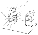
図1に示すように、本実施例の内視鏡洗浄消毒管理システムとしての内視鏡システム1は、内視鏡装置2及び内視鏡洗浄消毒装置3とを備えて構成される。
As shown in FIG. 1, an
前記内視鏡装置2は、内視鏡(以下、スコープとも記す)4を保持するための可撓性を有するアーム12と、前記内視鏡4に搭載された撮像素子(図示せず)により撮像された撮像信号を信号処理して内視鏡画像を生成するためのビデオプロセッサ6と、前記内視鏡4に照明光を供給するための光源装置5と、前記内視鏡4に対して送気・送水及び吸引を行う送気送水装置7と、前記ビデオプロセッサ6が生成した前記内視鏡画像を表示する為の例えば液晶モニタ等からなる告知手段としてのモニタ11から構成される。
The
これらビデオプロセッサ6、光源装置5及び送気送水装置7は、図2に示すように、カート8に積層的に、搭載・配置されている。前記カート8は、下部に電源部14を有しており、この電源部14からの電力を、ビデオプロセッサ6、光源装置5及び送気送水装置7に供給するようになっている。
The
前記カート8は、支柱上部にモニタ11を前後左右に回転自在に保持すると共に、支柱上部のモニタ11の配置位置の下部には作業用の作業プレート9が設けられている。この作業プレート9上に、例えばキーボードあるいはポインティングデバイスとしてのマウス(図示せず)等を配置することで、前記内視鏡装置2は、キーボードあるいはマウス等によりビデオプロセッサ6、光源装置5及び送気送水装置7に対して各種データの入力及び設定ができる。
The
また、ビデオプロセッサ6は、リモートコントローラ(以下、リモコンと記す)13が着脱自在に接続できるようになっている。このリモコン13を術者が操作することで、内視鏡4の後述する湾曲部の湾曲操作の制御や、内視鏡4が撮像した画像のレリーズあるいはフリーズ等の画像制御が、内視鏡4による体腔内検査中に容易に行うことができる。
The
また、前記内視鏡装置2は、前記内視鏡4と前記ビデオプロセッサ6とを電気的に接続する信号ケーブル15と、前記光源装置5からの前記照明光を前記内視鏡4を伝送するためのライトガイドケーブル16とを、前記アーム12内に挿通させる。そして、前記アーム12内の信号ケーブル15及びライトガイドケーブル16の基端部を前記アーム12のアームコネクタ12aにて終端させて、アームコネクタ12aを前記ビデオプロセッサ6に接続させて構成される。
The
前記内視鏡4は、図2に示すように、内視鏡挿入部4aと、ユニバーサルケーブル4b と、管路チューブ4c とから構成される。そして、ユニバーサルケーブル4b はアーム12に並設もしくは内蔵されており、ユニバーサルケーブル4b と接続されているアームコネクタ12aを前記ビデオプロセッサ6に接続することで、ユニバーサルケーブル4b は、信号ケーブル15により前記ビデオプロセッサ6に電気的に接続される。同時にライトガイドケーブル16により前記光源装置5からの前記照明光がユニバーサルケーブル4b に伝送されるようになっている。なお、アームコネクタ12aは、前記ビデオプロセッサ6に着脱自在に接続される。
As shown in FIG. 2, the
図3に示すように、内視鏡挿入部4aは、先端に撮像素子(例えば、CCDあるいはC-MOSセンサ等)30を有し、基端側にユニバーサルケーブル4b の先端部と管路チューブ4c の先端部とを着脱自在に接続できる。
As shown in FIG. 3, the
また、内視鏡挿入部4aは、内部に、挿入軸に沿って、先端面が内視鏡挿入部4aの先端面にて開口した複数の管路からなる送気送水管路群32を配置しており、この送気送水管路群32の基端面は前記管路チューブ4c の先端面に接続されるようになっている。この管路チューブ4c の基端部は、前記送気送水装置7に着脱自在に接続される。なお、この管路チューブ4c は、1回の検査毎に使い捨てられるチューブ、いわゆるディスポーザブルチューブにより構成される。
In addition, the
上述したように、内視鏡挿入部4aの基端側にユニバーサルケーブル4b の先端部を接続した状態で、前記ビデオプロセッサ6は、信号ケーブル15を介して内視鏡挿入部4に設けられた撮像素子30を駆動/制御することができるようになっている。
As described above, the
また、内視鏡挿入部4aの先端部には湾曲駒からなる湾曲部29が設けられており、内視鏡挿入部4aの先端部は、湾曲部29に連結された複数、例えば4本の湾曲ワイヤ28を、内視鏡挿入部4aの基端部内に設けた湾曲駆動ユニット26により進退させることで、上下左右に湾曲部29を湾曲させることができるように構成されている。
Further, a
そして、内視鏡挿入部4aの基端側にユニバーサルケーブル4b の先端部を接続した状態で、ユニバーサルケーブル4b を前記ビデオプロセッサ6に接続することで、前記ビデオプロセッサ6は、信号ケーブル15を介して内視鏡挿入部4aに設けられた湾曲駆動ユニット26を駆動/制御することができるようになっている。
The
すなわち、内視鏡挿入部4aの基端側にユニバーサルケーブル4b の先端部を接続すると、内視鏡挿入部4aの基端側に設けられたコネクタ部25a及び26aと、ユニバーサルケーブル4b の先端部に設けられたコネクタ部25b 及び26b と、が電気的もしくは機械的に接続される。
That is, when the distal end portion of the
したがって、内視鏡挿入部4aの基端側にユニバーサルケーブル4b の先端部を接続した状態で、前記ビデオプロセッサ6からの電気信号が、信号ケーブル15、コネクタ部25a及びコネクタ部25b を介して撮像素子30に伝送される。また、この状態で、前記ビデオプロセッサ6からの電気信号はまた、信号ケーブル15、コネクタ部26a及びコネクタ部26b を介して湾曲駆動ユニット26に伝送される。
Therefore, the electric signal from the
一方、内視鏡挿入部4aは、内部に、ライトガイド27aを挿入軸に沿って配置している。ライトガイド27aの先端面は、図示しない対物光学系を介して内視鏡挿入部4aの先端面に水密な状態で開口している。また、ライトガイド27aの基端面は、内視鏡挿入部4の基端側にユニバーサルケーブル4b の先端部を接続した場合に、ユニバーサルケーブル4b 内を挿通しているライトガイド27b の先端面に、光学特性を劣化させることなく、光学的に接続される。さらに、ライトガイド27b の基端面は、ユニバーサルケーブル4b の基端部を前記アーム12のアームコネクタ12aに接続した場合に、前記アーム12内を挿通しているライトガイド16の先端面に、光学特性を劣化させることなく、光学的に接続される。
On the other hand, the
したがって、内視鏡挿入部4の基端側にユニバーサルケーブル4b の先端部を接続した状態で、光源装置5からの照明光が、アーム12内のライトガイド16、ユニバーサルケーブル4b 内のライトガイド27b 及び内視鏡挿入部4a内のライトガイド27aを介して、内視鏡挿入部4aの先端に伝送することとなる。そして、内視鏡挿入部4aの先端に伝送された照明光は、内視鏡挿入部4aの先端面内に設けられた図示しない対物光学系を介して、先端前方に位置する被写体に照射される。
Therefore, in a state where the distal end portion of the
また、本実施例では、内視鏡挿入部4aは基端内部に第1の時間記憶手段としてのRF-ID(Radio Frequency IDentification)部23(RF-ID素子)を有し、ユニバーサルケーブル4b は先端内部にRF-ID部22を有して、それぞれ構成されている。さらに、ユニバーサルケーブル4b は先端内部に、これらRF-ID部22、23と無線にてデータを送受し、信号ケーブル15を介してビデオプロセッサ6と有線にて前記データを送受するRF-IDアンテナ部21を有している(図4参照:図4は図3の1点破線円で示す、ユニバーサルケーブル4b は先端面を示す図)。
In the present embodiment, the
前記リモコン13は、図5に示すように、外表面に、前記ビデオプロセッサ6を介して湾曲駆動ユニット26の駆動を指示する、例えばジョイスティック型の湾曲スイッチ13b と、ビデオプロセッサ6でのレリーズ、フリーズ等の各種制御し指示する、複数の指示スイッチ13c〜13eが設けられている。また、リモコン13は、内部にRF-ID部13aを有して構成される。このRF-ID部13aは、リモコン13をユニバーサルケーブル4b に近づけることにより、 RF-IDアンテナ部21と無線にてデータを送受するようになっている。
As shown in FIG. 5, the
なお、前記RF-ID部22、23は、内視鏡4のIDであるスコープID(機種名、製造番号等の識別情報、管路特性情報等)及び、各種機器固有データ(使用回数、修理履歴情報、CCD特性データ等)、システムデータ(検査実施年月日、検査開始時間、検査終了時間、使用機器データ、検査実施者等)、洗浄消毒の履歴データ(洗浄消毒実施年月日、洗浄消毒終了時間、洗浄消毒回数、使用洗浄消毒装置情報、洗浄消毒実施者等)、等からなる内視鏡検査システムデータ(以下、単に検査データと記す)の書き込み、読み込みが可能なメモリ部(図示せず)を有して構成されている。
The RF-
前記ビデオプロセッサ6は、図6に示すように、内視鏡4の内視鏡挿入部4aに設けられた撮像素子30を駆動するCCDドライバ601と、前記撮像素子30からの撮像信号を前処理(例えば、相関2重サンプリング、輝度調整、A/D変換等)する前処理部602を備えている。
As shown in FIG. 6, the
また、ビデオプロセッサ6は、前処理部602により前処理された、デジタル化した映像信号に対して信号処理(例えば、ホワイトバランス処理、色調整、γ補正等)する映像信号処理部603と、映像信号処理部603にて信号処理された映像信号に基づき、モニタ11に表示する表示画像を生成する表示画像生成部604を有している。
In addition, the
さらに、ビデオプロセッサ6は、内視鏡4のユニバーサルケーブル4b に設けられたRF-IDアンテナ部21を駆動し、RF-IDアンテナ部21を介してRF-ID部22、23及び13aと検査データを送受するRF-ID R/W部605を有している。
Further, the
また、ビデオプロセッサ6は、リモコン13の指示信号を受信するリモコンI/F(インターフェイス)部608と、光源装置5及び送気送水装置7とシリアル通信(例えばRS-232C通信)を行うシリアルI/F部606とを有している。
The
そして、ビデオプロセッサ6は、上記各部を制御部609にて制御すると共に、制御部609はタイマ607を用いて各種制御を時間管理し、制御状態の来歴を図示しないデータ記憶部にてロギングしている。
The
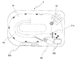
内視鏡洗浄消毒装置3は、図7に示すように、上面に操作パネル303及びLCD表示部302(図1参照)を備えている。
As shown in FIG. 7, the endoscope cleaning /
なお、LCD表示部302は、タッチパネル機能を有し、このタッチパネル機能により内視鏡洗浄消毒装置3はユーザインターフェイスを実現している。
The
また、内視鏡洗浄消毒装置3は、内部に、所定の深さを備えた槽部である洗浄槽3aを備えている。この洗浄槽3内に、例えば内視鏡挿入部4aが所定の位置に配置されるようになっている。このとき、内視鏡挿入部4aの管路チューブ4c が接続される接続面が、洗浄槽3aの外側近傍に設けられる洗浄ブラシユニット301のブラシ進退方向と略直交するように、内視鏡挿入部4aが配置される。また、内視鏡洗浄消毒装置3は、このとき、内視鏡挿入部4aのユニバーサルケーブル4b が接続される接続面の、洗浄槽3aの外側近傍となる位置に、RF-IDアンテナ部21aを配置している。
Further, the endoscope cleaning /
内視鏡洗浄消毒装置3は、内視鏡挿入部4aのRF-ID部23内の検査データに基づき、洗浄ブラシユニット301により内視鏡挿入部4aの送気送水管路群32(図3参照)内を所定時間、ブラッシングした後、洗浄槽3aに洗浄液、消毒液等を送り込み、所定時間、洗浄及び消毒処理を行う。その後、内視鏡洗浄消毒装置3は、濯ぎ、乾燥処理を行う。この内視鏡洗浄消毒装置3での一連の処理の説明は後述する。
The endoscope cleaning /
内視鏡洗浄消毒装置3は、図8に示すように、洗浄及び消毒処理を制御する洗浄/消毒制御部311と、洗浄ブラシユニット301によるブラッシングを制御する洗浄ブラシ制御部312と、濯ぎ、乾燥処理を制御する濯ぎ/乾燥制御部313と、操作パネル303を制御する操作パネル制御部315と、LCD表示部302の表示制御及びタッチパネル機能制御を行うLCD制御部317とを備えている。
As shown in FIG. 8, the endoscope cleaning /
また、内視鏡洗浄消毒装置3は、RF-IDアンテナ部21aを駆動し、RF-IDアンテナ部21aを介して内視鏡挿入部4aのRF-ID部23と検査データを送受する、RF-ID読み出し書き込み手段としてのRF-ID R/W部314を有している。
In addition, the endoscope cleaning /
そして、内視鏡洗浄消毒装置3は、上記各部を制御部318にて制御すると共に、制御部318は現在時刻計測手段としてのタイマ316を用いて各種制御を時間管理し、制御状態の来歴を図示しないデータ記憶部にてロギングしている。本実施例では、洗浄及び消毒工程制御手段と、時間比較手段とは、制御部318により構成される。
The endoscope cleaning /
このように構成された本実施例の作用を図9ないし図15を用いて説明する。 The operation of the present embodiment thus configured will be described with reference to FIGS.
内視鏡検査の開始に先立ち、術者により、内視鏡挿入部4aにユニバーサルケーブル4b 及び管路チューブ4c を接続して内視鏡4が組み立てられる。そして、術者により、ユニバーサルケーブル4b がビデオプロセッサ6に接続されると共に、管路チューブ4c が送気送水装置7に接続される。このとき、リモコン13も術者により、ビデオプロセッサ6に接続される。
Prior to the start of the endoscopy, the operator assembles the
この状態で、術者によりビデオプロセッサ6、光源装置5及び送気送水装置7の電源がオンされることで、内視鏡装置2による検査が可能な状態となる。
In this state, the operator turns on the power of the
内視鏡装置2による検査が可能な状態となると、ビデオプロセッサ6においては、図9に示すように、制御部609(図6参照)は、ステップS1にてビデオプロセッサ6内のシステムの各部の初期化処理を実行する。
When the inspection by the
そして、制御部609は、ステップS2にてユニバーサルケーブル4b のRF-IDアンテナ部21(図3参照)を介してRF-ID部23より検査データを読み出す。
In step S2, the
続いて、制御部609は、ステップS3にて、読み出した検査データより、少なくとも洗浄消毒の履歴データの洗浄消毒実施年月日、洗浄消毒終了時間(以下、単に洗浄消毒終了時刻データと記す)を抽出・確認する。
Subsequently, in step S3, the
なお、この洗浄消毒終了時刻データは、後述するように、内視鏡洗浄消毒装置3により、例えば内視鏡挿入部4aが洗浄されるタイミングで更新されるが、内視鏡挿入部4aの製品出荷時には、所定のデフォルトコードとして記録されている。
As will be described later, the cleaning / disinfecting end time data is updated by the endoscope cleaning /
次に、制御部609は、ステップS3にて、確認した洗浄消毒時刻データと、タイマ607が示す、現在の年月日及び時刻(以下、単に現在時刻データ)とを比較し、洗浄消毒終了時刻データと現在時刻データとの差分が所定時間以内かどうか判定する。
Next, in step S3, the
まず、洗浄消毒終了時刻データと現在時刻データとの差分が所定時間以内の場合は、制御部609は、ステップS5にて、接続されている内視鏡4による検査が可能状態で有ると認識し、ステップS6にて検査が終了するまで、ステップS5〜S6を繰り返す。
First, if the difference between the cleaning / disinfecting end time data and the current time data is within a predetermined time, the
検査の終了を確認すると、制御部609は、ステップS7にてタイマ607が示す、現在時刻データを検査終了時刻データとして確認する。
When the end of the inspection is confirmed, the
そして、制御部609は、ステップS8にて、ユニバーサルケーブル4b のRF-IDアンテナ部21を介してRF-ID部23に、確認した検査終了時刻データを検査データの検査終了時間として上書きして検査終了時間を更新し、処理を終了する。
Then, in step S8, the
このステップS8のとき、制御部609はユニバーサルケーブル4b のRF-IDアンテナ部21を介して、ユニバーサルケーブル4b のRF-ID部22及びリモコン13のRF-ID部13aにも確認した検査終了時間が検査データの検査終了時間として書き込む。
At the time of this step S8, the
一方、ステップS4において洗浄消毒終了時刻データと現在時刻データとの差分が所定時間を超えていると判断すると、制御部609は、ステップS9にて、図10に示すようなエラー画面を告知手段としてのモニタ11に表示する。このエラー画面において術者がマウス等を用いてポインタ11aによりOKボタン11c を操作すると、処理を終了する。
On the other hand, if it is determined in step S4 that the difference between the cleaning / disinfecting end time data and the current time data exceeds a predetermined time, the
このように本実施例では、ビデオプロセッサ6が検査開始に前に、内視鏡4の、少なくとも内視鏡挿入部4aの洗浄消毒終了時刻データを現在時刻データとリアルタイムで比較しているので、確実に、洗浄消毒終了時間が所定時間以内の内視鏡4の、少なくとも内視鏡挿入部4aを検査に使用することができる。
As described above, in this embodiment, the
次に、このようにして、検査に使用された内視鏡4の、少なくとも内視鏡挿入部4aの内視鏡洗浄消毒装置3における、洗浄消毒処理について説明する。
Next, the cleaning / disinfecting process in the endoscope cleaning /
術者が検査に使用された内視鏡挿入部4aを洗浄槽3aにセットし、内視鏡洗浄消毒装置3の電源をオンすると、内視鏡洗浄消毒装置3による洗浄消毒処理が開始される。
When the operator inserts the
洗浄消毒処理が開始されると、内視鏡洗浄消毒装置3において、図11に示すように、制御部318(図8参照)は、ステップS31にて内視鏡洗浄消毒装置3内のシステムの各部の初期化処理を実行する。
When the cleaning / disinfecting process is started, in the endoscope cleaning /
そして、制御部318は、ステップS32にて内視鏡洗浄消毒装置3のRF-IDアンテナ部21a(図7参照)を介してRF-ID部23より検査データを読み出す。
In step S32, the
続いて、制御部318は、ステップS33にて、読み出した検査データより、少なくともシステムデータの検査実施年月日、検査終了時間(以下、単に検査終了時刻データと記す)を抽出・確認する。
Subsequently, in step S33, the
なお、この検査終了時刻データは、前述したように、ビデオプロセッサ6により、内視鏡検査の終了のタイミングで更新されるが、内視鏡挿入部4aの製品出荷時には、所定のデフォルトコードとして記録されている。
As described above, the examination end time data is updated by the
次に、制御部318は、ステップS34にて、確認した検査終了時刻データと、タイマ316が示す、現在時刻データとを比較し、検査終了時刻データと現在時刻データとの差分が所定時間以内かどうか判定する。
Next, in step S34, the
まず、検査終了時刻データと現在時刻データとの差分が所定時間以内の場合は、制御部318は、ステップS35にてLCD表示部302(図7参照)に、図12に示すような時間設定画面を表示し、術者のLCD表示部302におけるタッチパネル機能による操作結果を待つ。
First, when the difference between the examination end time data and the current time data is within a predetermined time, the
具体的には、例えば図12の時間設定画面において、術者が自動ボタン302aを操作しかつOKボタン302d を操作すると、制御部318はステップS35よりステップS36に処理を移行する。また術者がマニュアルボタン302b を操作しかつOKボタン302d を操作すると、制御部318はステップS35よりステップS41に処理を移行する。
Specifically, for example, when the operator operates the
ステップS36では、制御部318は、検査終了時刻データ(すなわち、検査終了時刻データと現在時刻データとの差分時間)に基づき、洗浄ブラシユニット301によるブラッシング時間(=ブラシ時間)、洗浄時間及び消毒時間を算出し、ステップS37に進む。
In step S36, the
一方、ステップS41では、図12の時間設定画面において、マニュアル設定エリア302c がアクティブとなり、制御部318は、術者によるマニュアル設定エリア302c でのブラッシング時間(=ブラシ時間)、洗浄時間及び消毒時間設定の操作を待ち、ステップS42にて術者によるOKボタン302d が操作されるまで、制御部318は、ステップS41〜S42を繰り返す。そして、ステップS42にて術者によるOKボタン302d を確認すると、ステップS37に進む(または、所定時間内であれば、自動的に次のステップに移行してもよい)。
On the other hand, in step S41, the
ステップS37では、制御部318は、算出あるいは設定されたブラッシング時間(=ブラシ時間)、洗浄時間及び消毒時間のブラッシング、洗浄及び消毒処理を行うと共に、濯ぎ及び乾燥処理を実行する。制御部318は、このステップS37での処理の終了をステップS38で確認するまで、ステップS37〜S38の処理を繰り返す。そして、制御部318は、ステップS38にてステップS37での処理の終了を確認すると、ステップS39に進む。
In step S37, the
ステップS37での処理の終了を確認すると、制御部318は、ステップS39にてタイマ316が示す、現在時刻データを洗浄消毒終了時刻データとして確認する。
Upon confirming the end of the process in step S37, the
そして、制御部318は、ステップS40にて、内視鏡洗浄消毒装置3のRF-IDアンテナ部21a(図7参照)を介してRF-ID部23に、確認した洗浄消毒終了時刻データを検査データの洗浄消毒終了時間として上書きし洗浄消毒終了時間を更新し、かつ処理回数データをインクリメントして更新し、処理を終了する。
In step S40, the
次に、ステップS34において、検査終了時刻データと現在時刻データとの差分が所定時間を超えていると判断した場合の処理について説明する。 Next, a process when it is determined in step S34 that the difference between the examination end time data and the current time data exceeds a predetermined time will be described.
制御部318は、ステップS34において、検査終了時刻データと現在時刻データとの差分が所定時間を超えていると判断した場合、処理をステップS43に移行する。
If the
ステップS43では、制御部318は、図13に示すような前処理である前洗浄を要求する前処理要求画面をLCD表示部302に表示し、検査終了時刻データと現在時刻データとの差分が所定時間を超えていることを警告する。
In step S43, the
そして、制御部318は、ステップS44にて、図13の前処理要求画面において、術者がLCD表示部302におけるタッチパネル機能により、前洗浄済みボタン302eを操作したかあるいはOKボタン302eを操作したかどうか判断する。
In step S44, the
ここで、前処理である前洗浄とは、術者あるいは看護士が手動で洗浄ブラシ(図示せず)を用い、内視鏡挿入部4aの外表面及び、送気送水管路群32(図3参照)の各管路内を所定時間、所定の方法にてブラッシングする処理をいう。
Here, pre-cleaning, which is pretreatment, is performed manually by an operator or nurse using a cleaning brush (not shown), and the outer surface of the
そして、ステップS44において前洗浄済みボタン302eが操作されたと判断すると、制御部318は、図14に示すような時間設定画面をLCD表示部302に表示し、処理をステップS41に移行する。
If it is determined in step S44 that the
また、ステップS44において前洗浄済みボタン302eではなくOKボタン302eが操作されたと判断すると、図15に示すような警告画面をLCD表示部302に表示し、処理を終了する。
If it is determined in step S44 that the
このように本実施例では、内視鏡洗浄消毒装置3は、洗浄消毒対象である内視鏡挿入部4aの検査終了時刻を現在時刻と比較し、検査終了時刻が所定時間以内ならば自動あるいはマニュアルで設定した時間に基づき、自動ブラッシング、自動洗浄及び自動消毒を実行し、検査終了時刻が所定時間経過している場合は、内視鏡挿入部4aの前洗浄を警告するので、確実かつ効果的に内視鏡挿入部4aをブラッシング、洗浄及び消毒することができ、内視鏡の使用後の所定時間経過に基づいた内視鏡洗浄消毒処理を行うことができる。
Thus, in this embodiment, the endoscope cleaning /
なお、本実施例では、例えばRF-ID部23を内視鏡挿入部4aの基端部内に設けるとしたが、これに限らず、図16に示すように、例えば内視鏡挿入部4aの基端部の外表面にRF-ID部23の代わりにRF-ID部401を設けてもよい。この場合、RF-ID部401は、例えば表示内容を維持するための電源が不要な、公知の電子ペーパのような表示部を兼ね備えてもよく、検査終了時間及び洗浄消毒終了時間を表示させるようにしてもよい。電子ペーパのような表示部に検査終了時間及び洗浄消毒終了時間を表示させることで、内視鏡挿入部4aのセッティング前に、内視鏡挿入部4aの検査終了時間及び洗浄消毒終了時間を容易に確認することができる。
In this embodiment, for example, the RF-
また、図17に示すように、内視鏡挿入部4aの基端部に着脱自在のタグ402にRF-ID部23の代わりにRF-ID部403を設けてもよい。この場合も、RF-ID部403は、例えば表示内容を維持するための電源が不要な、公知の電子ペーパのような表示部を兼ね備えてもよく、検査終了時間及び洗浄消毒終了時間を表示させるようにしてもよい。
In addition, as shown in FIG. 17, an RF-
図18ないし図22は本発明の実施例2に係わり、図18は内視鏡挿入部を内部に格納する内視鏡用トレイの外観を示す図、図19は図18の内視鏡用トレイに対応したビデオプロセッサの処理の流れを示すフローチャート、図20は図19の処理を説明する図、図21は図18の内視鏡用トレイに対応した内視鏡洗浄消毒装置の処理の流れを示すフローチャート、図22は図21の処理を説明する図である。 18 to 22 relate to the second embodiment of the present invention, FIG. 18 is a view showing the appearance of an endoscope tray that houses the endoscope insertion portion therein, and FIG. 19 is an endoscope tray of FIG. FIG. 20 is a diagram for explaining the process of FIG. 19, and FIG. 21 is a flowchart of the process of the endoscope cleaning / disinfecting apparatus corresponding to the endoscope tray of FIG. FIG. 22 is a flowchart for explaining the processing of FIG.
実施例2は、実施例1とほとんど同じであるので、異なる点のみ説明し、同一の構成には同じ符号をつけ説明は省略する。 Since the second embodiment is almost the same as the first embodiment, only different points will be described, and the same components are denoted by the same reference numerals and description thereof will be omitted.
本実施例では、図18に示すように、内視鏡検査前及び、検査終了後に内視鏡挿入部4aを収納し、内視鏡挿入部4aの運搬、洗浄・消毒、保管を行う内視鏡用トレイ103が用意されている。
In this embodiment, as shown in FIG. 18, the
この内視鏡用トレイ103は、内視鏡洗浄消毒装置3の洗浄槽3a(図7参照)に直接装填(格納)でき、内視鏡洗浄消毒装置3にて、この内視鏡用トレイ103毎、内視鏡挿入部4aをブラッシング、洗浄及び消毒できる構造となっている。
The
また、内視鏡用トレイ103の外表面にはRF-ID部70が設けられている。なお、本実施例では、図示はしないが、このRF-ID部70と無線にてデータを送受し、ビデオプロセッサ6に伝送する、RF-IDアンテナ部がアーム12あるいは作業プレート9(図1参照)の近傍に配置されている。また、この場合、RF-ID部70は、例えば表示内容を維持するための電源が不要な、公知の電子ペーパのような表示部を兼ね備えてもよく、検査終了時間及び洗浄消毒終了時間を表示させるようにしてもよい。電子ペーパのような表示部に検査終了時間及び洗浄消毒終了時間を表示させることで、内視鏡挿入部4aのセッティング前に、内視鏡挿入部4aの検査終了時間及び洗浄消毒終了時間を容易に確認することができる。
In addition, an RF-
この場合の送受信用のRFIDアンテナは、ビデオプロセッサ6からカート8に外部アンテナとして取り付ける方法や、ユニバーサルコード4b の先端に搭載する方法など、内視鏡装置2(あるいはカート8)の近傍でかつRF-ID部70との通信が確保できる位置であれば何処でも設置しても良い。この場合も内視鏡挿入部4a←→ユニバーサルコード4b ←→ビデオプロセッサ6の経路において無線で信号伝達される(アンテナの位置によりビデオプロセッサ6⇔内視鏡挿入部4a、ビデオプロセッサ6←→ユニバーサルコード4b 、ビデオプロセッサ6←→リモコン13の経路も可能)。
The RFID antenna for transmission / reception in this case is an RF antenna near the endoscope apparatus 2 (or the cart 8) such as a method of attaching the
また、RF-ID部70は、内視鏡用トレイ103を内視鏡洗浄消毒装置3にセットした際に、内視鏡洗浄消毒装置3のRF-IDアンテナ部21a(図7参照)を介して内視鏡洗浄消毒装置3の制御部318とデータの送受が可能な位置に配置されるようになっている。
Further, when the
本実施例では、内視鏡挿入部4aも実施例1と同様に、基端部内にRF-ID部23を有しているため、説明を明確にするため、本実施例では、以下、内視鏡挿入部4aのRF-ID部23をスコープRF-ID23と記し、内視鏡用トレイ103のRF-ID部70をトレイRF-ID70と記す。その他の構成は実施例1と同じである。
In the present embodiment, the
このように構成された本実施例の作用を図19ないし図22を用いて説明する。本実施例では、内視鏡挿入部4aは、内視鏡用トレイ103に内に格納され、運搬、保管される。また、内視鏡挿入部4aは、内視鏡用トレイ103に内に格納された状態で、内視鏡洗浄消毒装置3内に内視鏡用トレイ103をセットし、ブラッシング、洗浄、消毒等の処理がなされる。
The operation of this embodiment configured as described above will be described with reference to FIGS. In the present embodiment, the
本実施例では、内視鏡挿入部4aを内部に格納している内視鏡用トレイ103を作業プレート9(図1参照)に置き、内視鏡用トレイ103から内視鏡挿入部4aを取り出す。このとき、空の内視鏡用トレイ103は、作業プレート9上に放置される。
In the present embodiment, an
そして、実施例1と同様に、内視鏡検査の開始に先立ち、術者により、内視鏡挿入部4aにユニバーサルケーブル4b 及び管路チューブ4c を接続して内視鏡4が組み立てられる。そして、術者により、ユニバーサルケーブル4b がビデオプロセッサ6に接続されると共に、管路チューブ4c が送気送水装置7に接続される。このとき、リモコン13も術者により、ビデオプロセッサ6に接続される。
Similarly to the first embodiment, prior to the start of the endoscopy, the operator connects the
この状態で、術者によりビデオプロセッサ6、光源装置5及び送気送水装置7の電源がオンされることで、内視鏡装置2による検査が可能な状態となる。
In this state, the operator turns on the power of the
内視鏡装置2による検査が可能な状態となると、ビデオプロセッサ6においては、図19に示すように、制御部609(図6参照)は、ステップS1にてビデオプロセッサ6内のシステムの各部の初期化処理を実行する。
When the inspection by the
そして、制御部609は、ステップS51にて、ユニバーサルケーブル4b のRF-IDアンテナ部21(図3参照)を介してスコープRF-ID23より検査データを読み出し、スコープRF-ID23に記録されているスコープ側の洗浄消毒終了時刻データを抽出する。さらに、制御部609は、ステップS52にて、作業プレート9あるいはアーム12の近傍に設けられたRF-IDアンテナ部(図示せず)を介してトレイRF-ID70より検査データを読み出し、トレイRF-ID23に記録されているトレイ側の洗浄消毒終了時刻データを抽出する。
In step S51, the
次に、制御部609は、ステップS53にて、ステップS51において抽出したスコープ側の洗浄消毒終了時刻データと、ステップS52において抽出したトレイ側の洗浄消毒終了時刻データを比較し、その差分時間が所定時間以内かどうかで、両洗浄消毒終了時刻データが一致しているかどうか判定する。
Next, in step S53, the
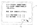
スコープ側の洗浄消毒終了時刻データとトレイ側の洗浄消毒終了時刻データとの差分時間が所定時間を超え、両洗浄消毒終了時刻データが一致していないと判断すると、制御部609は、ステップS9にて、図20に示すようなエラー画面をモニタ11に表示する。このエラー画面において術者がマウス等を用いてポインタ11aによりOKボタン11c を操作すると、処理を終了する。
When it is determined that the difference time between the scope-side cleaning / disinfection end time data and the tray-side cleaning / disinfection end time data exceeds a predetermined time and the both cleaning / disinfection end time data do not match, the
一方、スコープ側の洗浄消毒終了時刻データとトレイ側の洗浄消毒終了時刻データとの差分時間が所定時間以内で、両洗浄消毒終了時刻データが一致していると判断すると、制御部609は、処理をステップS3に移行する。なお、ステップS3〜ステップS7までの処理は実施例1と同じである(図9参照)ので、説明は省略する。
On the other hand, when it is determined that the difference time between the cleaning / disinfecting end time data on the scope side and the cleaning / disinfecting end time data on the tray side is within a predetermined time and the both cleaning / disinfecting end time data match, the
そして、ステップS7において制御部609はタイマ607が示す、現在時刻データを検査終了時刻データとして確認すると、制御部609は、ステップS54にて、ユニバーサルケーブル4b のRF-IDアンテナ部21を介してスコープRF-ID23に、確認した検査終了時刻データを検査データの検査終了時間として上書きして検査終了時間を更新し、処理を終了する。
In step S7, when the
また、このステップS54のとき、制御部609は、作業プレート9あるいはアーム12の近傍に設けられたRF-IDアンテナ部(図示せず)を介して、トレイRF-ID70にも確認した検査終了時間が検査データの検査終了時間として書き込む。
Further, at the time of this step S54, the
このように本実施例では、ビデオプロセッサ6が検査開始に前に、内視鏡挿入部4aの洗浄消毒終了時刻データと、内視鏡挿入部4aを内部に格納している内視鏡用トレイ103の洗浄消毒終了時刻データとを比較し、その差分時間が所定時間を超えている場合、警告するので、内視鏡用トレイ103の洗浄消毒終了時刻データと一致しない洗浄消毒終了時刻データを有する内視鏡挿入部4aの検査の使用を避けることができる。
As described above, in this embodiment, before the
すなわち、内視鏡用トレイ103の洗浄消毒終了時刻データと、内視鏡挿入部4aの洗浄消毒終了時刻データとが一致しないというのは、内視鏡用トレイ103内に格納され、運搬、保管されているはずの、内視鏡用トレイ103を運搬、保管中に内視鏡用トレイ103から内視鏡挿入部4aが入れ替わった恐れが有る。
That is, the fact that the cleaning / disinfecting end time data of the
本実施例は、このような場合に対しても、図20に示したエラー画面をモニタ11に表示して警告を行うことで、再度、内視鏡用トレイ103に格納した状態での内視鏡挿入部4aの洗浄、消毒処理を術者に促すので、内視鏡用トレイ103の洗浄消毒終了時刻データと一致しない洗浄消毒終了時刻データを有する内視鏡挿入部4aの検査の使用を避けることができる。
In the present embodiment, even in such a case, the error screen shown in FIG. 20 is displayed on the
また、実施例1と同様に、ビデオプロセッサ6が検査開始に前に、内視鏡4の、少なくとも内視鏡挿入部4aの洗浄消毒終了時刻データを現在時刻データとリアルタイムで比較しているので、確実に、洗浄消毒終了時間が所定時間以内の内視鏡4の、少なくとも内視鏡挿入部4aを検査に使用することができる。
Similarly to the first embodiment, the
次に、このようにして、検査に使用された内視鏡4の、少なくとも内視鏡挿入部4aの内視鏡洗浄消毒装置3における、洗浄消毒処理について説明する。
Next, the cleaning / disinfecting process in the endoscope cleaning /
術者が検査に使用された内視鏡挿入部4a格納している内視鏡用トレイ103を洗浄槽3aにセットし、内視鏡洗浄消毒装置3の電源をオンすると、内視鏡洗浄消毒装置3による洗浄消毒処理が開始される。
When the operator sets the
洗浄消毒処理が開始されると、内視鏡洗浄消毒装置3において、図21に示すように、制御部318(図8参照)は、ステップS31にて内視鏡洗浄消毒装置3内のシステムの各部の初期化処理を実行する。
When the cleaning / disinfecting process is started, in the endoscope cleaning /
そして、制御部318は、ステップS61にて、内視鏡洗浄消毒装置3のRF-IDアンテナ部21a(図7参照)を介してスコープRF-ID23より検査データを読み出し、スコープRF-ID23に記録されているスコープ側の検査終了時刻データを抽出する。さらに、制御部318は、ステップS62にて、内視鏡洗浄消毒装置3のRF-IDアンテナ部21aを介してトレイRF-ID70より検査データを読み出し、トレイRF-ID70に記録されているトレイ側の洗浄消毒終了時刻データを抽出する。
In step S61, the
次に、制御部318は、ステップS63にて、ステップS61において抽出したスコープ側の洗浄消毒終了時刻データと、ステップS62において抽出したトレイ側の洗浄消毒終了時刻データを比較し、その差分時間が所定時間以内かどうかで、両洗浄消毒終了時刻データが一致しているかどうか判定する。
Next, in step S63, the
スコープ側の洗浄消毒終了時刻データとトレイ側の洗浄消毒終了時刻データとの差分時間が所定時間を超え、両洗浄消毒終了時刻データが一致していないと判断すると、制御部318は、ステップS43にて、図22に示すような前処理である前洗浄を要求する前処理要求画面をLCD表示部302に表示し、検査終了時刻データと現在時刻データとの差分が所定時間を超えていることを警告し、ステップS44に処理を移行する。
When it is determined that the difference between the scope-side cleaning / disinfection end time data and the tray-side cleaning / disinfection end time data exceeds a predetermined time and the cleaning / disinfection end time data does not match, the
一方、スコープ側の洗浄消毒終了時刻データとトレイ側の洗浄消毒終了時刻データとの差分時間が所定時間以内で、両洗浄消毒終了時刻データが一致していると判断すると、制御部318は、処理をステップS33に移行する。なお、ステップS33〜ステップS45までの処理は実施例1と同じである(図11参照)ので、説明は省略する。
On the other hand, when it is determined that the difference time between the cleaning / disinfecting end time data on the scope side and the cleaning / disinfecting end time data on the tray side is within a predetermined time and the both cleaning / disinfecting end time data match, the
そして、ステップS39において制御部318はタイマ316が示す、現在時刻データを洗浄消毒終了時刻データとして確認すると、制御部318は、ステップS64にて、内視鏡洗浄消毒装置3のRF-IDアンテナ部21a(図7参照)を介してスコープRF-ID23及びトレイRF-ID70に、確認した洗浄消毒終了時刻データを検査データの洗浄消毒終了時間として上書きし洗浄消毒終了時間を更新し、かつ処理回数データをインクリメントして更新し、処理を終了する。
In step S39, when the
このように本実施例では、内視鏡洗浄消毒装置3は、洗浄消毒処理前に、内視鏡挿入部4aの洗浄消毒終了時刻データと、内視鏡挿入部4aを内部に格納している内視鏡用トレイ103の洗浄消毒終了時刻データとを比較し、その差分時間が所定時間を超えている場合、警告するので、内視鏡用トレイ103の洗浄消毒終了時刻データと一致しない洗浄消毒終了時刻データを有する内視鏡挿入部4aの前処理である前洗浄の実施を術者に促すことができる。
Thus, in this embodiment, the endoscope cleaning /
すなわち、内視鏡用トレイ103の洗浄消毒終了時刻データと、内視鏡挿入部4aの洗浄消毒終了時刻データとが一致しないというのは、内視鏡用トレイ103内に格納され、運搬、保管されているはずの、内視鏡用トレイ103を運搬、保管中に内視鏡用トレイ103から内視鏡挿入部4aが入れ替わった恐れが有る。
That is, the fact that the cleaning / disinfecting end time data of the
本実施例は、このような場合に対しても、図22に示した前処理である前洗浄を要求する前処理要求画面をモニタ11に表示して警告を行うのでで、内視鏡挿入部4aの前処理である前洗浄の実施を術者に促すことができる。 Even in this case, the present embodiment displays a pre-processing request screen for requesting pre-cleaning, which is the pre-processing shown in FIG. The operator can be encouraged to perform pre-cleaning, which is the pretreatment of 4a.
また、実施例1と同様に、内視鏡洗浄消毒装置3は、洗浄消毒対象である内視鏡挿入部4aの検査終了時刻を現在時刻と比較し、検査終了時刻が所定時間以内ならば自動あるいはマニュアルで設定した時間に基づき、自動ブラッシング、自動洗浄及び自動消毒を実行し、検査終了時刻が所定時間経過している場合は、内視鏡挿入部4aの前洗浄を警告するので、確実かつ効果的に内視鏡挿入部4aをブラッシング、洗浄及び消毒することができ、内視鏡の使用後の所定時間経過に基づいた内視鏡洗浄消毒処理を行うことができる。
Similarly to the first embodiment, the endoscope cleaning /
図23ないし図30は本発明の実施例3に係わり、図23は内視鏡システムの構成を示すシステム外観図、図24は図23の内視鏡システムを背面よりみた外観図、図25は図23の内視鏡の構成を示す図、図26は図23のビデオプロセッサの構成を示すブロック図、図27は図23の内視鏡洗浄消毒装置の構成を示すブロック図、図28は図23の内視鏡システムのシステム接続状態を示すシステム接続図、図29は図26のビデオプロセッサの処理の流れを示すフローチャート、図30は図27の内視鏡洗浄消毒装置の処理の流れを示すフローチャートである。 23 to 30 relate to the third embodiment of the present invention, FIG. 23 is a system external view showing the configuration of the endoscope system, FIG. 24 is an external view of the endoscope system of FIG. 23 as viewed from the back, and FIG. FIG. 26 is a block diagram showing the configuration of the video processor of FIG. 23, FIG. 27 is a block diagram showing the configuration of the endoscope cleaning / disinfecting device of FIG. 23, and FIG. 23 is a system connection diagram showing a system connection state of the endoscope system, FIG. 29 is a flowchart showing a process flow of the video processor of FIG. 26, and FIG. 30 shows a process flow of the endoscope cleaning / disinfecting apparatus of FIG. It is a flowchart.
実施例3は、実施例1とほとんど同じであるので、異なる点のみ説明し、同一の構成には同じ符号をつけ説明は省略する。 Since the third embodiment is almost the same as the first embodiment, only different points will be described, and the same components are denoted by the same reference numerals and description thereof will be omitted.
図23に示すように、本実施例の内視鏡洗浄消毒管理システムとしての内視鏡システム1aは、内視鏡装置2と、内視鏡洗浄消毒装置3と、内視鏡検査支援装置100と、内視鏡第1保管庫101aと、内視鏡第2保管庫101b とを備えて構成される。
As shown in FIG. 23, an
図24に示すように、内視鏡装置2のビデオプロセッサ6及び光源装置5と、内視鏡洗浄消毒装置3と、内視鏡検査支援装置100と、内視鏡第1保管庫101aと、内視鏡第2保管庫101b とは、それぞれLAN接続部200を背面に有しており、LAN接続ケーブル201をこれらLAN接続部200に接続することで、各装置を院内LANに接続できるようになっている。
As shown in FIG. 24, the
内視鏡検査支援装置100は、LAN接続部200及びLAN接続ケーブル201を介してネットワーク接続されるビデオプロセッサ6、内視鏡洗浄消毒装置3、内視鏡第1保管庫101a及び内視鏡第2保管庫101b とデータを送受することで、内視鏡のID(機種名、製造番号等の識別情報、管路特性情報等)であるスコープID毎に、内視鏡検査の業務(例えば、カルテ作成、管理、検査予約、検査実施記録、洗浄消毒実施記録、履歴管理など)の検査情報を管理し支援する処理を行う装置である。
The endoscope
内視鏡第1保管庫101及び内視鏡第2保管庫101b は、実施例2で説明した内視鏡挿入部4aを内部に格納している内視鏡用トレイ103毎に保管する保管庫である。
The endoscope first storage 101 and the endoscope
また、本実施例の内視鏡装置2のビデオプロセッサ6に接続される内視鏡4において、図25に示すように、内視鏡挿入部4は、基端側内部にスコープRF-ID23近傍に、検査データの書き込み、読み込みが可能なIDメモリ部250aが設けられ、このIDメモリ部250aはコネクタ部25aを介してビデオプロセッサ6に電気的に接続されている。
Further, in the
同様に、内視鏡4において、ユニバーサルケーブル4b は、先端側内部にスコープRF-ID22近傍に、検査データの書き込み、読み込みが可能なIDメモリ部250b が設けられ、このIDメモリ部250b はコネクタ部25b を介してビデオプロセッサ6に電気的に接続されている。
Similarly, in the
本実施例の内視鏡装置2のビデオプロセッサ6は、図26に示すように、RF-IDアンテナ部を介してRF-ID部と検査データを送受するRF-ID R/W部605を有しておらず、従来のビデオプロセッサと同様に、IDメモリ部250a及びIDメモリ部250b と電気的に接続され、IDメモリ部250a及びIDメモリ部250b に対して検査データを書き込み、読み込みの制御を行うスコープID R/W部605aが設けられている。
As shown in FIG. 26, the
さらに、本実施例のビデオプロセッサ6は、LAN接続部200に接続され、院内LANとネットワーク接続するためのLAN I/F部610を有して構成される。
Furthermore, the
また、本実施例の内視鏡洗浄消毒装置3は、図27に示すように、LAN接続部200に接続され、院内LANとネットワーク接続するためのLAN I/F部320を有して構成される。
In addition, as shown in FIG. 27, the endoscope cleaning /
図28に本実施例の内視鏡システムのシステム接続図を示すが、図28に示すように、ビデオプロセッサ6に接続されるリモコン13にも、RF-ID部13a近傍に、検査データの書き込み、読み込みが可能なIDメモリ部251が設けられ、このIDメモリ部251はビデオプロセッサ6に電気的に接続されている。
その他の構成は実施例1と同じである。
FIG. 28 shows a system connection diagram of the endoscope system of the present embodiment. As shown in FIG. 28, the test data is also written to the
Other configurations are the same as those of the first embodiment.
このように構成された本実施例の作用を図29及び図30を用いて説明する。 The operation of this embodiment configured as described above will be described with reference to FIGS.
内視鏡検査の開始に先立ち、術者により、内視鏡挿入部4aにユニバーサルケーブル4b 及び管路チューブ4c を接続して内視鏡4が組み立てられる。そして、術者により、ユニバーサルケーブル4b がビデオプロセッサ6に接続されると共に、管路チューブ4c が送気送水装置7に接続される。このとき、リモコン13も術者により、ビデオプロセッサ6に接続される。
Prior to the start of the endoscopy, the operator assembles the
この状態で、術者によりビデオプロセッサ6、光源装置5及び送気送水装置7の電源がオンされることで、内視鏡装置2による検査が可能な状態となる。
In this state, the operator turns on the power of the
内視鏡装置2による検査が可能な状態となると、ビデオプロセッサ6においては、図29に示すように、制御部609は、ステップS1にてビデオプロセッサ6内のシステムの各部の初期化処理を実行する。
When the inspection by the
そして、制御部609は、ステップS81にてスコープID R/W部605aを介してIDメモリ部250aより検査データの内の内視鏡のID(機種名、製造番号等の識別情報、管路特性情報等)であるスコープIDを読み出す。
In step S81, the
続いて、制御部609は、ステップS82にて、LAN I/F部610を介して内視鏡検査支援装置100にネットワーク接続し、内視鏡検査支援装置100より、読み出したスコープIDに基づいて、内視鏡挿入部4aの洗浄消毒終了時刻データを抽出・確認し、ステップS3に進む。
Subsequently, in step S82, the
なお、ステップS3以降の処理は、ステップS8の代わりにステップS83の処理が行われる点が実施例1と異なるので、ステップS83のみ説明し、その他省略する。 Since the processing after step S3 is different from the first embodiment in that the processing of step S83 is performed instead of step S8, only step S83 will be described and the others will be omitted.
ステップS7において制御部609はタイマ607が示す、現在時刻データを検査終了時刻データとして確認すると、制御部609は、ステップS83にて、LAN I/F部610を介して内視鏡検査支援装置100にネットワーク接続し、内視鏡検査支援装置100に、確認した検査終了時刻データを検査データの検査終了時間として上書きして検査終了時間を更新し、処理を終了する。
In step S7, when the
次に、このようにして、検査に使用された内視鏡4の、少なくとも内視鏡挿入部4aの内視鏡洗浄消毒装置3における、洗浄消毒処理について説明する。
Next, the cleaning / disinfecting process in the endoscope cleaning /
実施例2と同様に、術者が検査に使用された内視鏡挿入部4a格納している内視鏡用トレイ103を洗浄槽3aにセットし、内視鏡洗浄消毒装置3の電源をオンすると、内視鏡洗浄消毒装置3による洗浄消毒処理が開始される。
Similarly to the second embodiment, the
洗浄消毒処理が開始されると、内視鏡洗浄消毒装置3において、図30に示すように、制御部318は、ステップS31にて内視鏡洗浄消毒装置3内のシステムの各部の初期化処理を実行する。
When the cleaning / disinfecting process is started, in the endoscope cleaning /
そして、制御部318は、ステップS91にて、内視鏡洗浄消毒装置3のRF-IDアンテナ部21a(図7参照)を介してスコープRF-ID23より内視鏡のID(機種名、製造番号等の識別情報、管路特性情報等)であるスコープIDを読み出す。
Then, in step S91, the
そして、制御部318は、ステップS92にて、LAN I/F部320を介して内視鏡検査支援装置100にネットワーク接続し、内視鏡検査支援装置100より、読み出したスコープIDに基づいて、内視鏡挿入部4aの検査終了時刻データを抽出する。そして、制御部318は、ステップS92にて、抽出した検査終了時刻データを検査終了時間と確認して、ステップS33に進む。
In step S92, the
なお、ステップS33以降の処理は、ステップS40の代わりにステップS94の処理が行われる点が実施例1と異なるので、ステップS94のみ説明し、その他省略する。 In addition, since the process after step S33 differs from Example 1 in the point that the process of step S94 is performed instead of step S40, only step S94 is demonstrated and others are abbreviate | omitted.
ステップS39において制御部318はタイマ316が示す、現在時刻データを洗浄消毒終了時刻データとして確認すると、制御部318は、ステップS64にて、LAN I/F部320を介して内視鏡検査支援装置100にネットワーク接続し、内視鏡検査支援装置100に、確認した洗浄消毒終了時刻データを検査データの洗浄消毒終了時間として上書きし洗浄消毒終了時間を更新し、かつ処理回数データをインクリメントして更新し、処理を終了する。
In step S39, when the
このように本実施例では、実施例1の効果に加え、内視鏡検査支援装置100において、スコープID毎に、内視鏡検査の業務(例えば、カルテ作成、管理、検査予約、検査実施記録、洗浄消毒実施記録、履歴管理など)を管理しているので、既存のIDメモリ部システム及びRFIDを搭載した内視鏡を用いることで、例えばRF-ID R/W部を有しない従来のビデオプロセッサ(例えば本実施例のビデオプロセッサ6)を流用でき、新たにRF-ID R/W部を新たに追加する必要することなく、内視鏡検査の終了時刻を容易にかつ、追加投資なしで入手でき、適切な洗浄消毒を実施することができる。
As described above, in the present embodiment, in addition to the effects of the first embodiment, the endoscopic
本発明は、上述した実施例に限定されるものではなく、本発明の要旨を変えない範囲において、種々の変更、改変等が可能である。 The present invention is not limited to the above-described embodiments, and various changes and modifications can be made without departing from the scope of the present invention.
1…内視鏡システム
2…内視鏡装置
3…内視鏡洗浄消毒装置
4…内視鏡
4a…内視鏡挿入部
4b…ユニバーサルケーブル
4c…管路チューブ
5…光源装置
6…ビデオプロセッサ
7…送気送水装置
13…リモコン
21…RF-IDアンテナ部
22、23…RF-ID部
DESCRIPTION OF
Claims (8)
前記内視鏡を、少なくとも洗浄及び消毒する内視鏡洗浄消毒装置と、
前記内視鏡検査装置における前記内視鏡検査の終了時間を記憶する第1の時間記憶手段と
を備え、
前記内視鏡洗浄消毒装置は、前記第1の時間記憶手段が記憶した前記内視鏡検査の終了時間に基づき、前記内視鏡の、少なくとも洗浄及び消毒工程を制御する洗浄及び消毒工程制御手段を有する
ことを特徴とする内視鏡洗浄消毒管理システム。 An endoscope inspection apparatus that performs an endoscopic inspection using an endoscope having an insertion portion that is inserted into a lumen;
An endoscope cleaning / disinfecting apparatus for cleaning and disinfecting the endoscope at least;
First time storage means for storing an end time of the endoscopy in the endoscopy device,
The endoscope cleaning and disinfecting apparatus is a cleaning and disinfecting process control unit that controls at least a cleaning and disinfecting process of the endoscope based on an end time of the endoscopy stored in the first time storage unit. An endoscope cleaning / disinfecting management system characterized by comprising:
前記RF-ID素子に対して前記データを読み出し及び書き込みするRF-ID読み出し書き込み手段をさらに有する
ことを特徴とする請求項1に記載の内視鏡洗浄消毒管理システム。 The first storage means includes an RF-ID element provided in a proximal end portion of the insertion portion of the endoscope and capable of updating data wirelessly,
The endoscope cleaning / disinfecting management system according to claim 1, further comprising RF-ID reading / writing means for reading and writing the data with respect to the RF-ID element.
ことを特徴とする請求項1に記載の内視鏡洗浄消毒管理システム。 The endoscope cleaning / disinfecting management system according to claim 1, wherein the first storage unit is configured to be connected to at least the endoscope inspection apparatus and the endoscope cleaning / disinfecting apparatus via a network.
ことを特徴とする請求項1ないし3のいずれか1つに記載の内視鏡洗浄消毒管理システム。 The first storage means stores the end time of the endoscopy for each endoscope identification information for identifying the endoscope stored in the storage means in the endoscope. The endoscope cleaning / disinfecting management system according to any one of claims 1 to 3.
少なくとも、前記第1の時間記憶手段が記憶している前記内視鏡検査の終了時間と比較するための、現在時刻を計測する現在時刻計測手段と、
前記現在時刻と前記第1の時間記憶手段が記憶している前記内視鏡検査の終了時間との時間差を、予め設定した規定時間と比較する時間比較手段と、
前記時間比較手段が前記時間差と前記規定時間とを比較した結果、前記時間差が前記規定時間を超えていると判断した場合、前記内視鏡検査の終了時間が前記規定時間を超えていることを告知する告知手段と
をさらに備えた
ことを特徴とする請求項1ないし4のいずれか1つに記載の内視鏡洗浄消毒管理システム。 The endoscope cleaning / disinfecting apparatus is
At least current time measuring means for measuring a current time for comparison with an end time of the endoscopy stored in the first time storage means;
A time comparison means for comparing a time difference between the current time and the end time of the endoscopic examination stored in the first time storage means with a preset specified time;
As a result of the time comparison means comparing the time difference with the specified time, if it is determined that the time difference exceeds the specified time, the end time of the endoscopy exceeds the specified time. The endoscope cleaning / disinfecting management system according to any one of claims 1 to 4, further comprising notification means for notifying.
ことを特徴とする請求項1ないし5のいずれか1つに記載の内視鏡洗浄消毒管理システム。 6. The cleaning and disinfection process control means determines and controls at least the start of the cleaning and disinfection process of the endoscope based on the end time of the endoscopy. The endoscope cleaning / disinfecting management system according to any one of the above.
前記洗浄及び消毒工程制御手段は、前記現在時刻と前記第1の時間記憶手段が記憶している前記内視鏡検査の終了時間との比較結果に基づき、前記洗浄ブラシユニットによる前記チャンネル内の自動ブラシ洗浄の洗浄条件を制御して、前記洗浄及び消毒工程を制御する
ことを特徴とする請求項1ないし6のいずれか1つに記載の内視鏡洗浄消毒管理システム。 The endoscope cleaning / disinfecting apparatus has a cleaning brush unit that automatically cleans the inside of a channel provided along an insertion axis in the endoscope,
The cleaning and disinfecting process control means is configured to perform automatic processing in the channel by the cleaning brush unit based on a comparison result between the current time and the end time of the endoscopy stored in the first time storage means. The endoscope cleaning / disinfecting management system according to any one of claims 1 to 6, wherein the cleaning and disinfecting steps are controlled by controlling cleaning conditions for brush cleaning.
少なくとも、前記洗浄及び消毒工程制御手段は、前記第1の記憶手段に記憶されている前記内視鏡検査装置における前記内視鏡検査の終了時間を、前記LANを介して前記内視鏡検査支援装置より取得する
ことを特徴とする請求項1ないし7のいずれか1つに記載の内視鏡洗浄消毒管理システム。 The first storage means is connected to at least the endoscopy device and the endoscope cleaning / disinfecting device via a LAN, manages endoscopy information, and supports an examination. Provided in
At least the cleaning and disinfection process control means is configured to determine the end time of the endoscopic examination in the endoscopic examination apparatus stored in the first storage means via the LAN. The endoscope cleaning / disinfecting management system according to any one of claims 1 to 7, wherein the system is acquired from an apparatus.
Priority Applications (5)
| Application Number | Priority Date | Filing Date | Title |
|---|---|---|---|
| JP2006158811A JP2007325724A (en) | 2006-06-07 | 2006-06-07 | Management system for cleaning and disinfection of endoscope |
| CNA2007101084112A CN101084823A (en) | 2006-06-07 | 2007-06-07 | System and method for managing cleaning and disinfecting steps for endoscope |
| KR1020070055438A KR20070117482A (en) | 2006-06-07 | 2007-06-07 | System and method for managing process of cleaning and disinfecting of endoscope |
| US11/810,909 US20070286764A1 (en) | 2006-06-07 | 2007-06-07 | System and method for managing cleaning and disinfecting steps for endoscope |
| EP07011272A EP1864607B1 (en) | 2006-06-07 | 2007-06-08 | System for managing cleaning and disinfecting steps for endoscope |
Applications Claiming Priority (1)
| Application Number | Priority Date | Filing Date | Title |
|---|---|---|---|
| JP2006158811A JP2007325724A (en) | 2006-06-07 | 2006-06-07 | Management system for cleaning and disinfection of endoscope |
Publications (2)
| Publication Number | Publication Date |
|---|---|
| JP2007325724A true JP2007325724A (en) | 2007-12-20 |
| JP2007325724A5 JP2007325724A5 (en) | 2009-07-09 |
Family
ID=38523434
Family Applications (1)
| Application Number | Title | Priority Date | Filing Date |
|---|---|---|---|
| JP2006158811A Withdrawn JP2007325724A (en) | 2006-06-07 | 2006-06-07 | Management system for cleaning and disinfection of endoscope |
Country Status (5)
| Country | Link |
|---|---|
| US (1) | US20070286764A1 (en) |
| EP (1) | EP1864607B1 (en) |
| JP (1) | JP2007325724A (en) |
| KR (1) | KR20070117482A (en) |
| CN (1) | CN101084823A (en) |
Cited By (6)
| Publication number | Priority date | Publication date | Assignee | Title |
|---|---|---|---|---|
| JP2009172013A (en) * | 2008-01-21 | 2009-08-06 | Olympus Medical Systems Corp | Endoscope washing/disinfecting device |
| WO2011046715A2 (en) * | 2009-10-13 | 2011-04-21 | Augusta E.N.T., P.C. | Medical instrument cleaning system and method |
| JP2012239536A (en) * | 2011-05-17 | 2012-12-10 | Fujifilm Corp | Washing management device, program, and endoscope management system |
| JP2014147643A (en) * | 2013-02-04 | 2014-08-21 | Olympus Medical Systems Corp | Endoscope leakage inspection device and endoscope leakage inspection method |
| WO2019087599A1 (en) * | 2017-10-31 | 2019-05-09 | オリンパス株式会社 | Endoscope cleaning assistance device, method for operating endoscope cleaning assistance device, and endoscope cleaning assistance program |
| WO2019230082A1 (en) * | 2018-05-31 | 2019-12-05 | オリンパス株式会社 | Cleaning management device |
Families Citing this family (51)
| Publication number | Priority date | Publication date | Assignee | Title |
|---|---|---|---|---|
| JP2008029521A (en) * | 2006-07-27 | 2008-02-14 | Olympus Medical Systems Corp | Endoscope system |
| JP5100303B2 (en) * | 2007-10-17 | 2012-12-19 | 富士フイルム株式会社 | Endoscope information management system, cleaning information management system, and cleaning information management device |
| US20090267765A1 (en) * | 2008-04-29 | 2009-10-29 | Jack Greene | Rfid to prevent reprocessing |
| US10524645B2 (en) | 2009-06-18 | 2020-01-07 | Endochoice, Inc. | Method and system for eliminating image motion blur in a multiple viewing elements endoscope |
| US9474440B2 (en) | 2009-06-18 | 2016-10-25 | Endochoice, Inc. | Endoscope tip position visual indicator and heat management system |
| EP2575622B1 (en) * | 2010-06-03 | 2016-04-27 | B-K Medical ApS | Control device |
| US10663714B2 (en) | 2010-10-28 | 2020-05-26 | Endochoice, Inc. | Optical system for an endoscope |
| US9706908B2 (en) | 2010-10-28 | 2017-07-18 | Endochoice, Inc. | Image capture and video processing systems and methods for multiple viewing element endoscopes |
| US10517464B2 (en) | 2011-02-07 | 2019-12-31 | Endochoice, Inc. | Multi-element cover for a multi-camera endoscope |
| FR2977136B1 (en) * | 2011-06-28 | 2014-05-30 | Axess Vision Technology | IMAGING SYSTEM FOR CONTROLLED USE |
| CN102894946A (en) * | 2011-07-26 | 2013-01-30 | 中国人民解放军第二军医大学 | Whole-process intelligentized quality control system for cleanness and disinfection for gastrointestinal endoscopy |
| CN103796572B (en) * | 2012-08-31 | 2016-01-06 | 奥林巴斯株式会社 | Cleaning sterilizing device |
| US10537236B2 (en) | 2013-01-17 | 2020-01-21 | Stryker Corporation | Anti-fogging device for endoscope |
| US10582832B2 (en) | 2013-01-17 | 2020-03-10 | Stryker Corporation | System for altering functions of at least one surgical device dependent upon information saved in an endoscope related to the endoscope |
| US10143830B2 (en) | 2013-03-13 | 2018-12-04 | Crisi Medical Systems, Inc. | Injection site information cap |
| US9400900B2 (en) * | 2013-03-14 | 2016-07-26 | Wal-Mart Stores, Inc. | Method and apparatus pertaining to RFID tag-based user assertions |
| US9636003B2 (en) | 2013-06-28 | 2017-05-02 | Endochoice, Inc. | Multi-jet distributor for an endoscope |
| US10595714B2 (en) | 2013-03-28 | 2020-03-24 | Endochoice, Inc. | Multi-jet controller for an endoscope |
| CN105358043B (en) | 2013-05-07 | 2018-12-21 | 恩多巧爱思股份有限公司 | The white balance shell being used together with more observation element endoscopes |
| US10064541B2 (en) | 2013-08-12 | 2018-09-04 | Endochoice, Inc. | Endoscope connector cover detection and warning system |
| US9943218B2 (en) | 2013-10-01 | 2018-04-17 | Endochoice, Inc. | Endoscope having a supply cable attached thereto |
| US9968242B2 (en) | 2013-12-18 | 2018-05-15 | Endochoice, Inc. | Suction control unit for an endoscope having two working channels |
| WO2015112747A2 (en) | 2014-01-22 | 2015-07-30 | Endochoice, Inc. | Image capture and video processing systems and methods for multiple viewing element endoscopes |
| AU2015213485B2 (en) * | 2014-02-07 | 2020-05-28 | Smartline Holdings Pty Ltd | Device management system |
| JP5978240B2 (en) * | 2014-03-31 | 2016-08-24 | 富士フイルム株式会社 | Endoscope scope cleaning management system, endoscope scope cleaning management method, and program |
| US20150374206A1 (en) * | 2014-06-26 | 2015-12-31 | Endochoice, Inc. | Methods and Systems for Managing Information Generated From and Transmitted To An Endoscopic System |
| KR101488786B1 (en) * | 2014-06-30 | 2015-02-04 | 최대명 | endoscope managing system and method therefor |
| EP3171752B1 (en) | 2014-07-21 | 2019-12-11 | EndoChoice, Inc. | Multi-focal, multi-camera endoscope systems |
| US10542877B2 (en) | 2014-08-29 | 2020-01-28 | Endochoice, Inc. | Systems and methods for varying stiffness of an endoscopic insertion tube |
| US10123684B2 (en) | 2014-12-18 | 2018-11-13 | Endochoice, Inc. | System and method for processing video images generated by a multiple viewing elements endoscope |
| US10376181B2 (en) | 2015-02-17 | 2019-08-13 | Endochoice, Inc. | System for detecting the location of an endoscopic device during a medical procedure |
| US10078207B2 (en) | 2015-03-18 | 2018-09-18 | Endochoice, Inc. | Systems and methods for image magnification using relative movement between an image sensor and a lens assembly |
| US10401611B2 (en) | 2015-04-27 | 2019-09-03 | Endochoice, Inc. | Endoscope with integrated measurement of distance to objects of interest |
| US20170119474A1 (en) | 2015-10-28 | 2017-05-04 | Endochoice, Inc. | Device and Method for Tracking the Position of an Endoscope within a Patient's Body |
| AU2016361331B2 (en) | 2015-11-24 | 2021-10-28 | Endochoice, Inc. | Disposable air/water and suction valves for an endoscope |
| EP3419497B1 (en) | 2016-02-24 | 2022-06-01 | Endochoice, Inc. | Circuit board assembly for a multiple viewing element endoscope using cmos sensors |
| WO2017160792A1 (en) | 2016-03-14 | 2017-09-21 | Endochoice, Inc. | System and method for guiding and tracking a region of interest using an endoscope |
| WO2017222716A1 (en) | 2016-06-21 | 2017-12-28 | Endochoice, Inc. | Endoscope system with multiple connection interfaces to interface with different video data signal sources |
| CN106324190B (en) * | 2016-07-27 | 2019-05-07 | 3M创新有限公司 | Carrier member, endoscope cleaning effect detection device and method |
| EP3378375A1 (en) * | 2017-03-23 | 2018-09-26 | Stryker Corporation | System for altering functions of at least one surgical device dependent upon information saved in an endoscope related to the endoscope |
| CN108652574A (en) * | 2018-05-08 | 2018-10-16 | 梁徐勇 | A kind of multi-functional department of stomatology avoided infection pressure tongue device |
| EP3860426A4 (en) * | 2018-10-02 | 2022-12-07 | Convergascent LLC | Endoscope with inertial measurement units and/or haptic input controls |
| WO2020079777A1 (en) * | 2018-10-17 | 2020-04-23 | オリンパス株式会社 | Cleaning assistance system, processing device and cleaning assistance method |
| EP3986317A4 (en) * | 2019-06-20 | 2023-06-21 | Medivators Inc. | Endoscope storage cart, system and methods |
| KR102260497B1 (en) | 2019-07-17 | 2021-06-03 | (주)넥스빈 | Endoscope management system and method |
| US11439720B2 (en) | 2019-08-16 | 2022-09-13 | American Sterilizer Company | Method and apparatus to evaluate internal flexible endoscope channels in the context of endoscope ports and channel complexities |
| DE102019133463A1 (en) * | 2019-12-07 | 2021-06-10 | Martin Neumann | endoscope |
| CN111513665B (en) * | 2020-04-28 | 2023-08-29 | 诺信医学科技(山东)有限公司 | Gastroenterology scope belt cleaning device |
| CO2020006943A1 (en) * | 2020-06-05 | 2020-12-10 | Rodriguez Carlos Andres Hoyos | Invention implemented by computer for control in the manual disinfection of endoscopes. |
| DE102021126639A1 (en) | 2021-10-13 | 2023-04-13 | Olympus Winter & Ibe Gmbh | Delivery system for endoscopes |
| WO2024023859A1 (en) * | 2022-07-26 | 2024-02-01 | Cisa Production S.R.L. | Apparatus for the internal and external treatment of endoscopes |
Family Cites Families (7)
| Publication number | Priority date | Publication date | Assignee | Title |
|---|---|---|---|---|
| US4862872A (en) * | 1987-04-17 | 1989-09-05 | Olympus Optical Co., Ltd. | Endoscope and endoscope washing apparatus |
| US20020064479A1 (en) * | 1998-03-26 | 2002-05-30 | Nobuyuki Nakanishi | Apparatus for washing and disinfecting-sterilizing endoscope |
| JP3394742B2 (en) * | 1999-05-31 | 2003-04-07 | オリンパス光学工業株式会社 | Data filing system for endoscope |
| JP3791894B2 (en) * | 2000-05-12 | 2006-06-28 | オリンパス株式会社 | Endoscopic image filing system |
| JP3864035B2 (en) * | 2000-05-19 | 2006-12-27 | オリンパス株式会社 | Endoscope system |
| WO2002032468A1 (en) * | 2000-10-13 | 2002-04-25 | Olympus Optical Co., Ltd. | Automatic cleaning and disinfecting device |
| EP2319387A1 (en) * | 2002-03-18 | 2011-05-11 | Optim, Inc. | Sterilization apparatus |
-
2006
- 2006-06-07 JP JP2006158811A patent/JP2007325724A/en not_active Withdrawn
-
2007
- 2007-06-07 US US11/810,909 patent/US20070286764A1/en not_active Abandoned
- 2007-06-07 KR KR1020070055438A patent/KR20070117482A/en not_active Application Discontinuation
- 2007-06-07 CN CNA2007101084112A patent/CN101084823A/en active Pending
- 2007-06-08 EP EP07011272A patent/EP1864607B1/en not_active Expired - Fee Related
Cited By (12)
| Publication number | Priority date | Publication date | Assignee | Title |
|---|---|---|---|---|
| JP2009172013A (en) * | 2008-01-21 | 2009-08-06 | Olympus Medical Systems Corp | Endoscope washing/disinfecting device |
| WO2011046715A2 (en) * | 2009-10-13 | 2011-04-21 | Augusta E.N.T., P.C. | Medical instrument cleaning system and method |
| WO2011046715A3 (en) * | 2009-10-13 | 2011-06-30 | Augusta E.N.T., P.C. | Medical instrument cleaning system and method |
| US8816856B2 (en) | 2009-10-13 | 2014-08-26 | Augusta E.N.T., P.C. | Medical instrument cleaning system and method |
| JP2012239536A (en) * | 2011-05-17 | 2012-12-10 | Fujifilm Corp | Washing management device, program, and endoscope management system |
| JP2014147643A (en) * | 2013-02-04 | 2014-08-21 | Olympus Medical Systems Corp | Endoscope leakage inspection device and endoscope leakage inspection method |
| WO2019087599A1 (en) * | 2017-10-31 | 2019-05-09 | オリンパス株式会社 | Endoscope cleaning assistance device, method for operating endoscope cleaning assistance device, and endoscope cleaning assistance program |
| JP6542498B1 (en) * | 2017-10-31 | 2019-07-10 | オリンパス株式会社 | Endoscope cleaning operation support device, operation method of endoscope cleaning operation support device, and endoscope cleaning operation support program |
| US11812935B2 (en) | 2017-10-31 | 2023-11-14 | Olympus Corporation | Endoscope cleaning work support device, method of operating endoscope cleaning work support device, and endoscope cleaning work support program |
| WO2019230082A1 (en) * | 2018-05-31 | 2019-12-05 | オリンパス株式会社 | Cleaning management device |
| JPWO2019230082A1 (en) * | 2018-05-31 | 2021-03-11 | オリンパス株式会社 | Cleaning management device and cleaning management method |
| US11455509B2 (en) | 2018-05-31 | 2022-09-27 | Olympus Corporation | Cleaning management apparatus and cleaning management method |
Also Published As
| Publication number | Publication date |
|---|---|
| KR20070117482A (en) | 2007-12-12 |
| EP1864607A3 (en) | 2007-12-26 |
| EP1864607A2 (en) | 2007-12-12 |
| EP1864607B1 (en) | 2011-07-27 |
| US20070286764A1 (en) | 2007-12-13 |
| CN101084823A (en) | 2007-12-12 |
Similar Documents
| Publication | Publication Date | Title |
|---|---|---|
| JP2007325724A (en) | Management system for cleaning and disinfection of endoscope | |
| US20170135558A1 (en) | System and method for managing endoscopic scope | |
| US7115091B2 (en) | Reusable endoscopic device and related systems and methods | |
| JP5153476B2 (en) | Endoscope device | |
| EP1550465A1 (en) | Sterilizer and sterilizing method | |
| WO2005082230A1 (en) | Endoscope | |
| US20130345503A1 (en) | Hand-Operated Endoscope For Medical Purposes | |
| US20220240767A1 (en) | Medical device inspection scope | |
| JP2010088720A (en) | Endoscopic apparatus, ic tag for displaying state of endoscope, and method of displaying state of endoscopic apparatus | |
| JP4694308B2 (en) | Endoscope system | |
| US20140118518A1 (en) | Controlled-use imaging system | |
| JP5198961B2 (en) | Endoscope washing machine management system | |
| JP2006280592A (en) | Treatment supporting apparatus | |
| JP2011193982A (en) | History management system for endoscope reprocessor | |
| JP2009118883A (en) | Storage system of electronic endoscope and recovery system of electronic endoscope | |
| JP2001061760A (en) | Cover sheath type rigid endoscope | |
| JP2009118882A (en) | Preservation bag of electronic endoscope and preservation method of electronic endoscope | |
| JP2001095763A (en) | Medical appliance system | |
| JP2010063610A (en) | Reprocessing device | |
| JP4391663B2 (en) | Endoscope device | |
| JPH06254037A (en) | Endoscope cover with channel | |
| JP2005304778A (en) | Endoscope | |
| JP2009254610A (en) | Endoscope management system | |
| JP5135054B2 (en) | Endoscope and method for detecting water leakage of the endoscope | |
| JP2005304779A (en) | Endoscope |
Legal Events
| Date | Code | Title | Description |
|---|---|---|---|
| A521 | Request for written amendment filed |
Free format text: JAPANESE INTERMEDIATE CODE: A523 Effective date: 20090522 |
|
| A621 | Written request for application examination |
Free format text: JAPANESE INTERMEDIATE CODE: A621 Effective date: 20090522 |
|
| A761 | Written withdrawal of application |
Free format text: JAPANESE INTERMEDIATE CODE: A761 Effective date: 20091104 |