JP2007307205A - Apparatus and program of recognizing medical image section - Google Patents
Apparatus and program of recognizing medical image section Download PDFInfo
- Publication number
- JP2007307205A JP2007307205A JP2006140041A JP2006140041A JP2007307205A JP 2007307205 A JP2007307205 A JP 2007307205A JP 2006140041 A JP2006140041 A JP 2006140041A JP 2006140041 A JP2006140041 A JP 2006140041A JP 2007307205 A JP2007307205 A JP 2007307205A
- Authority
- JP
- Japan
- Prior art keywords
- image
- axial
- medical image
- discontinuity
- images
- Prior art date
- Legal status (The legal status is an assumption and is not a legal conclusion. Google has not performed a legal analysis and makes no representation as to the accuracy of the status listed.)
- Granted
Links
- 238000003384 imaging method Methods 0.000 claims abstract description 37
- 238000012937 correction Methods 0.000 claims abstract description 9
- 238000000034 method Methods 0.000 claims description 37
- 210000001015 abdomen Anatomy 0.000 claims description 19
- 238000013528 artificial neural network Methods 0.000 claims description 8
- 238000010801 machine learning Methods 0.000 claims description 3
- 210000004197 pelvis Anatomy 0.000 claims 2
- 238000012545 processing Methods 0.000 abstract description 27
- 238000004364 calculation method Methods 0.000 abstract description 11
- 238000002591 computed tomography Methods 0.000 description 16
- 230000006870 function Effects 0.000 description 6
- 238000002595 magnetic resonance imaging Methods 0.000 description 6
- 210000000988 bone and bone Anatomy 0.000 description 5
- 238000003745 diagnosis Methods 0.000 description 4
- 238000002059 diagnostic imaging Methods 0.000 description 4
- 238000010586 diagram Methods 0.000 description 4
- 238000002600 positron emission tomography Methods 0.000 description 4
- 238000002604 ultrasonography Methods 0.000 description 4
- 238000013459 approach Methods 0.000 description 2
- 238000004891 communication Methods 0.000 description 2
- 230000007423 decrease Effects 0.000 description 2
- 238000005516 engineering process Methods 0.000 description 2
- 238000007689 inspection Methods 0.000 description 2
- 238000002601 radiography Methods 0.000 description 2
- 230000003187 abdominal effect Effects 0.000 description 1
- 239000000470 constituent Substances 0.000 description 1
- 238000010276 construction Methods 0.000 description 1
- 238000001514 detection method Methods 0.000 description 1
- 229940079593 drug Drugs 0.000 description 1
- 239000003814 drug Substances 0.000 description 1
- 238000011156 evaluation Methods 0.000 description 1
- 239000000284 extract Substances 0.000 description 1
- 230000010365 information processing Effects 0.000 description 1
- 230000003902 lesion Effects 0.000 description 1
- 210000004072 lung Anatomy 0.000 description 1
- 238000005457 optimization Methods 0.000 description 1
- 210000000056 organ Anatomy 0.000 description 1
- 238000007781 pre-processing Methods 0.000 description 1
- 230000005855 radiation Effects 0.000 description 1
- 238000003325 tomography Methods 0.000 description 1
- 238000012285 ultrasound imaging Methods 0.000 description 1
- XLYOFNOQVPJJNP-UHFFFAOYSA-N water Substances O XLYOFNOQVPJJNP-UHFFFAOYSA-N 0.000 description 1
Images


Classifications
-
- G—PHYSICS
- G06—COMPUTING; CALCULATING OR COUNTING
- G06V—IMAGE OR VIDEO RECOGNITION OR UNDERSTANDING
- G06V10/00—Arrangements for image or video recognition or understanding
- G06V10/20—Image preprocessing
- G06V10/28—Quantising the image, e.g. histogram thresholding for discrimination between background and foreground patterns
-
- G—PHYSICS
- G06—COMPUTING; CALCULATING OR COUNTING
- G06V—IMAGE OR VIDEO RECOGNITION OR UNDERSTANDING
- G06V10/00—Arrangements for image or video recognition or understanding
- G06V10/40—Extraction of image or video features
- G06V10/44—Local feature extraction by analysis of parts of the pattern, e.g. by detecting edges, contours, loops, corners, strokes or intersections; Connectivity analysis, e.g. of connected components
- G06V10/457—Local feature extraction by analysis of parts of the pattern, e.g. by detecting edges, contours, loops, corners, strokes or intersections; Connectivity analysis, e.g. of connected components by analysing connectivity, e.g. edge linking, connected component analysis or slices
-
- G—PHYSICS
- G06—COMPUTING; CALCULATING OR COUNTING
- G06V—IMAGE OR VIDEO RECOGNITION OR UNDERSTANDING
- G06V2201/00—Indexing scheme relating to image or video recognition or understanding
- G06V2201/03—Recognition of patterns in medical or anatomical images
Landscapes
- Engineering & Computer Science (AREA)
- Physics & Mathematics (AREA)
- General Physics & Mathematics (AREA)
- Multimedia (AREA)
- Theoretical Computer Science (AREA)
- Computer Vision & Pattern Recognition (AREA)
- Measuring And Recording Apparatus For Diagnosis (AREA)
- Apparatus For Radiation Diagnosis (AREA)
- Magnetic Resonance Imaging Apparatus (AREA)
Abstract
Description
本発明は、医療用撮像モダリティによって取得された画像データに基づいて、医用画像に表されている体部の部位認識を行う医用画像部位認識装置、及び、そのような装置において用いられる医用画像部位認識プログラムに関する。 The present invention relates to a medical image region recognition device for recognizing a region of a body part represented in a medical image based on image data acquired by a medical imaging modality, and a medical image region used in such a device. It relates to recognition programs.
近年、医療診断においては、生体の内部が表示された医用画像が多く用いられており、そのような医用画像を取得するために、X線撮影や、X線CT(computed tomography:コンピュータ断層撮影)装置や、超音波(US)診断装置や、MRI(magnetic resonance imaging:磁気共鳴撮像)装置や、PET(positron emission tomography:ポジトロン断層撮影)等の様々な技術や装置(モダリティ)が広く利用されている。それらの装置の多くはディジタル化されており、病院内での診断情報処理システム等の構築が進められている。また、それらの撮像技術の内でも、CTやMRIは生体の軸位断画像を比較的狭い間隔で取得して表示できるので、生体の病変部位の発見や評価に大きな成果を上げている。ここで、軸位断画像とは、被検体の体軸に直交又はほぼ直交する面(所謂、輪切り面)が表された断層像のことをいう。以下において、軸位断画像のことを、単にスライス画像とも言う。 In recent years, medical images displaying the inside of a living body are often used in medical diagnosis, and in order to acquire such medical images, X-ray imaging or X-ray CT (computed tomography) is used. Various technologies and devices (modalities) such as devices, ultrasound (US) diagnostic devices, MRI (magnetic resonance imaging) devices, and PET (positron emission tomography) are widely used. Yes. Many of these devices have been digitized, and construction of diagnostic information processing systems and the like in hospitals is underway. Among these imaging technologies, CT and MRI can obtain and display biological dislocation images at relatively narrow intervals, and thus have achieved great results in the detection and evaluation of lesion sites in the living body. Here, the axial discontinuity image refers to a tomographic image in which a plane orthogonal to or approximately orthogonal to the body axis of the subject (so-called a circular cut surface) is represented. Hereinafter, the axial dislocation image is also simply referred to as a slice image.
ところで、CT検査等の断層撮像を行う際には、1回の検査において、必ずしも1部位のみ(例えば、胸部のみ、腹部のみ等)が撮像されるのではなく、複数の部位に渡って(例えば、胸部〜腹部、頭部〜胸部等)撮像が行われることが多い。一方、それによって得られた一連(1シリーズ)のスライス画像は、通常、撮像された方向に沿って順に画面表示される。そのため、スライス画像を観察して診断を行う医師は、読影に際して、まず、診断対象である部位が表されている画像を探すことから始めなければならない。しかしながら、1シリーズの画像は、通常、千数百枚〜数千枚に上るので、読影医の手間や負担はかなり大きい。そのため、膨大な量の画像の内から、所望の部位が表された画像を少ない労力で素早く表示できる装置やシステム等が望まれている。 By the way, when performing tomographic imaging such as CT examination, only one part (for example, only the chest, only the abdomen, etc.) is not necessarily imaged in one examination, but over a plurality of parts (for example, (Chest-abdomen, head-chest, etc.) imaging is often performed. On the other hand, a series (1 series) of slice images obtained thereby is normally displayed on the screen in order along the imaged direction. Therefore, a doctor who makes a diagnosis by observing a slice image must first start by searching for an image in which a region to be diagnosed is represented. However, since one series of images usually has several thousand to several thousand images, the labor and burden of the interpreting doctor is considerably large. Therefore, there is a demand for an apparatus, a system, and the like that can quickly display an image showing a desired part from a huge amount of images with little effort.
関連する技術として、特許文献1には、医用画像から画像処理によって自動的に撮像装置、部位、撮像方向等の撮像属性情報を抽出して管理情報に付加し、膨大な量の医用画像の効率的な管理を可能にするためのシステムが開示されている。この医用画像識別システムは、医用画像を記憶・管理するシステムであって、入力画像を分類する手段と、該分類ごとに識別すべきカテゴリに関するテンプレート画像を記憶するテンプレート画像記憶手段と、該テンプレート画像記憶手段から、入力画像の分類結果を用いて識別の候補となる複数のカテゴリのテンプレート画像を選択する手段と、選択されたテンプレート画像と入力画像とを比較し、最もよく一致するテンプレート画像のカテゴリを判定する画像識別手段と、上記テンプレート画像が有する管理情報を入力画像の管理情報に付加する手段とを有している(第2頁、図1)。即ち、特許文献1においては、入力画像のサイズや入力画像における矩形領域の数等に基づいて入力画像を分類し、その分類に応じて複数のカテゴリのテンプレート画像を選択し、選択されたテンプレート画像の内から、入力画像の濃淡情報やそのモザイク画像に一致するものを抽出し、そのテンプレート画像に付与されていた管理情報(例えば、撮像部位)を入力画像の管理情報として付与することにより、入力画像の撮像部位等を判断している。 As a related technique, Japanese Patent Laid-Open No. 2004-228561 automatically extracts imaging attribute information such as an imaging device, a part, and an imaging direction from a medical image by image processing and adds it to management information. A system for enabling efficient management is disclosed. The medical image identification system is a system for storing / managing medical images, a means for classifying input images, a template image storage means for storing a template image relating to a category to be identified for each classification, and the template image A means for selecting template images of a plurality of categories that are candidates for identification using the classification result of the input image from the storage means, and comparing the selected template image with the input image, and the category of the template image that best matches Image identification means for determining the management information, and means for adding the management information of the template image to the management information of the input image (second page, FIG. 1). That is, in Patent Document 1, an input image is classified based on the size of the input image, the number of rectangular areas in the input image, and the like, and template images of a plurality of categories are selected according to the classification, and the selected template image is selected. The input information is extracted by extracting the shade information of the input image or the one matching the mosaic image, and the management information (for example, imaging part) given to the template image is given as the management information of the input image. The imaging part of the image is determined.
しかしながら、1枚の医用画像には、常に1つの部位のみが表されているわけではない。例えば、画像の一部の領域には胸部が表示されており、別の一部の領域には腹部が表示されているというように、複数部位が表示されていることも多い。ところが、特許文献1には、複数部位が表示された画像に対する部位認識については一切記載されていない。 However, only one part is not always represented in one medical image. For example, a plurality of parts are often displayed such that a chest is displayed in a partial area of the image and an abdomen is displayed in another partial area. However, Patent Document 1 does not describe any part recognition for an image displaying a plurality of parts.
また、特許文献2には、画像データに撮像方向及び/又は撮像部位を表す撮像情報が付与されていない場合であっても、画像データに対して撮像方向及び/又は撮像部位に応じた最適な画像処理を施すための画像処理装置が開示されている。この画像処理装置は、医用画像を表す医用画像データに、該医用画像の撮像時における撮像部位及び/又は撮像方向を表す撮影情報が付与されているか否かを判断する判断手段と、撮像情報が付与されていない場合には、上記医用画像データに基づいて撮像部位及び/又は撮像方向の認識を行う認識手段と、該認識結果が上記撮像情報として医用画像データに付与する付与手段とを備えている(第2頁、図1)。そして、特許文献2においては、複数の画像データを用いて予め作成された固有画像を利用することにより撮像部位の認識が行われている(段落0038、及び、段落0019〜0023)。
しかしながら、特許文献2においても、1つの画像に対する部位認識しか行われていない。
However, in
そこで、上記の点に鑑み、本発明は、CTやMRI等のモダリティによって被検体を撮像検査することにより取得された1シリーズの軸位断画像について、各軸位断画像に表された体部の部位を効率良く認識する装置と、そのような装置において用いられるプログラムとを提供することを目的とする。 Therefore, in view of the above points, the present invention relates to a body part represented in each axial discontinuity image with respect to one series of axial discontinuity images obtained by imaging examination of a subject with a modality such as CT or MRI. It is an object of the present invention to provide an apparatus for efficiently recognizing the above-mentioned site and a program used in such an apparatus.
上記課題を解決するため、本発明の1つの観点に係る医用画像部位認識装置は、被検体を撮像検査することによって得られた1シリーズの軸位断画像を表す画像データに基づいて、複数の軸位断画像の各々に表された体部の部位を認識する装置であって、各軸位断画像に表された体部の部位を暫定的に決定する部位決定手段と、複数の軸位断画像に関する情報に基づいて、上記部位決定手段により少なくとも1つの軸位断画像について暫定的に決定された部位を修正する部位修正手段とを具備する。 In order to solve the above-described problem, a medical image region recognition device according to one aspect of the present invention is based on image data representing a series of axial discontinuity images obtained by imaging and inspecting a subject. A device for recognizing a part of a body part represented in each axial dislocation image, a part determining means for tentatively determining the part of the body part represented in each axial discontinuity image, and a plurality of axial positions And a part correcting unit that corrects a part temporarily determined for at least one axial position cut image by the part determining unit based on information on the cut image.
また、本発明の1つの観点に係る医用画像部位認識プログラムは、被検体を撮像検査することによって得られた1シリーズの軸位断画像を表す画像データに基づいて、複数の軸位断画像の各々に表された体部の部位を認識する装置において用いられるプログラムであって、各軸位断画像に表された体部の部位を暫定的に決定する手順(a)と、複数の軸位断画像に関する情報に基づいて、手順(a)において少なくとも1つの軸位断画像について暫定的に決定された部位を修正する手順(b)とをCPUに実行させる。 A medical image region recognition program according to one aspect of the present invention is based on image data representing a series of axial dislocation images obtained by imaging examination of a subject. A program for use in a device for recognizing a body part represented in each of the steps, wherein a procedure (a) for tentatively determining a body part represented in each axial dislocation image and a plurality of axial positions Based on the information about the broken image, the CPU executes the procedure (b) for correcting the part tentatively determined for at least one axial position broken image in the procedure (a).
本発明によれば、各軸位断画像について部位認識を行った後で、複数の軸位断画像に関する情報、即ち、複数の軸位断画像の集合によって表される被検体の3次元情報に基づいて、各軸位断画像に表された部位を修正するので、精度の高い部位認識を効率良く行うことが可能となる。 According to the present invention, after site recognition is performed on each axial dislocation image, information on a plurality of axial dislocation images, that is, three-dimensional information of the subject represented by a set of plural axial discontinuity images Based on this, the site represented in each axial dislocation image is corrected, so that highly accurate site recognition can be performed efficiently.
以下、本発明を実施するための最良の形態について、図面を参照しながら詳しく説明する。なお、同一の構成要素には同一の参照番号を付して、説明を省略する。
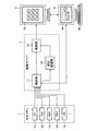
図1は、本発明の第1の実施形態に係る医用画像部位認識装置を含む医用画像撮影システムの構成を示すブロック図である。この医用画像撮影システムは、被検体について医用画像の撮像検査を行うモダリティ1と、画像サーバ2と、画像表示端末3と、読影用端末4とを含んでいる。これらの装置1〜4は、DICOM(Digital Imaging and Communications in Medicine)規格に準拠している。
Hereinafter, the best mode for carrying out the present invention will be described in detail with reference to the drawings. The same constituent elements are denoted by the same reference numerals, and the description thereof is omitted.
FIG. 1 is a block diagram showing a configuration of a medical image photographing system including a medical image region recognition apparatus according to the first embodiment of the present invention. This medical imaging system includes a modality 1 that performs a medical image imaging examination on a subject, an
モダリティ1は、CT装置1aや、CR(computed radiography)装置1bや、MRI装置1cや、PET装置1dや、超音波診断装置(US)1e等の医用画像撮像装置を含んでいる。これらのモダリティ1a〜1eは、撮像検査を行うことにより画像データを生成して、画像付帯情報と共に画像サーバ2に出力する。
The modality 1 includes a medical imaging apparatus such as a
画像サーバ2は、モダリティ1によって取得された画像データを保管及び管理するPACS(Picture Archiving and Communication System:医用画像情報システム)用のサーバである。この画像サーバ2は、医用画像部位認識機能を有しており、通常の画像サーバの動作(画像データの保管等)に加えて、医用画像部位認識装置としても動作する。画像サーバ2は、後述する読影用端末4の要求に従って、画像データを画像表示端末3に出力する。
The
図1に示すように、画像サーバ2は、制御部11と、部位認識部12と、格納部13とを有している。制御部11及び部位認識部12は、例えば、CPU(中央演算処理装置)と制御プログラムによって構成されている。
As illustrated in FIG. 1, the
制御部11は、モダリティ1から出力された画像データを格納部13に格納させる。また、制御部11は、入力された画像データによって表される画像の方向(軸位断(axial)、冠状断(coronal)、矢状断方向(sagittal)等)を確認し、軸位断方向である場合には、その画像データを部位認識部12にも出力する。なお、画像の方向は、例えば、DICOMタグ(0020,0037):Image Orientation(Patient)、又は、(0020,0020):Patient Orientationが付された画像付帯情報によって取得される。
The
部位認識部12は、1シリーズの画像データによって表される複数の軸位断画像(以下において、「スライス画像」ともいう)に基づいて、各軸位断画像に被検体のどの部位が表されているかを認識する。そして、認識結果(部位)を含む情報(部位情報)を生成し、画像データに関連付けて格納部13に格納させる。部位は、例えば、「Head(頭)」、「Neck(頸)」、「Chest(胸)」等のように、文字列によって示されても良いし、1:head、2:neck、3:chest等のように、予めコード化された整数値によって示されても良い。
The
格納部13は、例えば、画像サーバ2に内蔵されているハードディスクドライブであり、制御部11の制御の下で、画像データ及びその画像付帯情報や、部位認識部12によって生成された部位情報や、部位認識部12を動作させるための制御プログラム等を格納する。なお、記録媒体としては、ハードディスクの他に、MO、MT、RAM、CD−ROM、又は、DVD−ROM等を用いても良く、その場合には、それらの記録媒体を駆動する駆動装置が、画像サーバ2に内蔵され、又は、画像サーバ2の外部に接続される。
The
画像表示端末3は、検査画像が表示される端末装置であり、高精細なディスプレイを備えている。なお、図1に示す画像表示端末3の画面3aには、複数の軸位断画像が模式的に示されている。
読影用端末4は、ユーザ(読影医)が、画像表示端末3に表示された検査画像を参照しながら読影レポート等を作成するために用いられる装置であり、読影レポート等を表示する画面4aや、キーボード等の入力デバイス4b等を備えている。
The
The
次に、図1に示す部位認識部12の構成及び動作について、図2〜図4を参照しながら説明する。
図2は、図1に示す部位認識部12の機能を示すブロック図である。図2に示すように、部位認識部12は、特徴量計算部21と、部位確信度計算部22と、スコアテーブル記憶部22aと、部位決定処理部23と、部位情報記憶部24と、部位修正処理部25とを含んでいる。この内の特徴量計算部21〜部位決定処理部23は、各スライス画像について、そこに表された部位を暫定的に決定するように動作し、部位修正処理部25は、複数のスライス画像の部位情報に基づいて、各スライス画像について暫定的に決定された部位を修正するように動作する。なお、スライス画像の部位情報については後述する。
Next, the configuration and operation of the
FIG. 2 is a block diagram illustrating functions of the
図3は、部位認識部12の動作を示すフローチャートである。制御部11(図1)において軸位断画像を表すものであると判断された画像データが部位認識部12に入力されると、以下に説明する部位認識動作が開始される。
ステップS1において、画像データ及びその画像付帯情報は、1スライス分ごとに、特徴量計算部21に入力される。ここで、画像付帯情報には、画像の方向を表す情報((0020,0037):Image Orientation(Patient)、又は、(0020,0020):Patient Orientation)や、1画素のピッチを表す情報((0028,0030):Pixel Spacing)や、スライスの厚さを表す情報((0018,0050):Slice Thickness)や、1行及び1列に含まれる画素数を表す情報((0028,0010):Raws、及び、(0028,0011):Columns)や、画像の左上位置の3次元座標を表す情報((0020,0032):Image Position(Patient))等が含まれる。ここで、括弧内は、各情報のDICOMタグ及び属性名を示している。
FIG. 3 is a flowchart showing the operation of the
In step S <b> 1, the image data and the image supplementary information are input to the feature
ステップS2において、特徴量計算部21は、1つのスライス画像について特徴量を算出する。ここで、特徴量とは、スライス画像に表された体部の特徴を数値化したものである。特徴量は、例えば、次の(a)に示すように、スライス画像に表された体部の形状に基づいて算出される。また、各画素データの値(即ち、画素の輝度)が体部の特性(組織性状等)に対応している場合には、次の(b)や(c)に示すように、その値に応じて特徴量を算出しても良い。例えば、CT画像における画素データの値はCT値によって決定されるが、この値は、体部を透過した放射線量を表す物理量である。なお、水のCT値は0HUであり、空気領域のCT値は−1000HU程度であり、骨領域のCT値は250HU〜3000HU程度である。
In step S2, the feature
(a)体部全体の円形度
円形度ρは、対象領域の面積S及びその周囲の長さLを用いて、次式(1)によって算出される。
ρ=4πS/L2 …(1)
円形度ρは、対象領域の形状が真円に近づくほど1.0に近づき、形状が真円から離れるほど(例えば、楕円率が1から離れるほど)小さくなる。例えば、対象領域が頭部である場合には、円形度は比較的高くなる。反対に、対象領域が胸部や腹部である場合には、円形度は比較的低くなる。
(b)空気領域特徴量:(空気領域を示すCT値の画素数)/(体部全体の画素数)
例えば、対象領域が胸部である場合には、肺が存在しているために空気領域は比較的広くなる。反対に、対象領域が頭部である場合には、空気領域はほぼゼロとなる。
(c)骨領域特徴量:(骨領域を示すCT値の画素数)/(体部全体の画素数)
例えば、対象領域が腹部である場合には、体部全体に対する骨部の領域は比較的狭い範囲となる。反対に、対象領域が脚部である場合には、体部全体に対して骨部が多くの割合を占める。
(A) Circularity ρ of the whole body part The circularity ρ is calculated by the following equation (1) using the area S of the target region and the surrounding length L.
ρ = 4πS / L 2 (1)
The degree of circularity ρ approaches 1.0 as the shape of the target region approaches a perfect circle, and decreases as the shape moves away from the perfect circle (for example, the ellipticity goes away from 1). For example, when the target region is the head, the circularity is relatively high. On the other hand, when the target region is the chest or abdomen, the circularity is relatively low.
(B) Air region feature amount: (number of pixels of CT value indicating air region) / (number of pixels of the whole body)
For example, when the target region is the chest, the air region is relatively wide because the lungs are present. On the other hand, when the target area is the head, the air area is almost zero.
(C) Bone region feature amount: (number of pixels of CT value indicating bone region) / (number of pixels of entire body part)
For example, when the target region is the abdomen, the region of the bone portion relative to the entire body portion is a relatively narrow range. On the other hand, when the target region is the leg, the bone portion occupies a large proportion of the whole body portion.
次に、ステップS3において、部位確信度計算部13は、特徴量計算部12によって計算された特徴量に基づいて、部位確信度を算出する。ここで、部位確信度とは、対象部位が、「ある部位」である可能性(「頭部」らしさ、「胸部」らしさ等)を数値化したものである。本実施形態において、部位確信度は、予め用意されているスコアテーブルを用いて算出される。
Next, in step S <b> 3, the part certainty
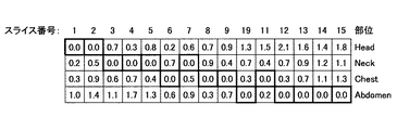
図4は、部位確信度の算出に用いられるスコアテーブルの例を示している。このスコアテーブルは、空気領域特徴量(空気量)の値に基づいて、「頭部」らしさ、「胸部」らしさ、「腹部」らしさ、及び、「脚部」らしさを求める際に用いられる。この他に、部位の項目として、「骨盤部」を挙げても良い。また、隣接する2つの部位の境界(境界領域)や、複数の部位が混在している領域(混在領域、例えば、頭部と頸部、又は、胸部と腹部等)を示す項目(例えば、「頭頸部」又は「胸腹部」)を挙げても良い。 FIG. 4 shows an example of a score table used for calculating the part certainty factor. This score table is used when obtaining the “head” -likeness, “chest” -likeness, “abdomen-like” -likeness, and “leg-likeness” -likeness based on the value of the air region feature quantity (air quantity). In addition to this, “pelvic part” may be cited as an item of the part. In addition, an item (for example, “a boundary region) between two adjacent parts or a region where a plurality of parts are mixed (a mixed region, for example, the head and neck, or the chest and abdomen). Head and neck ”or“ chest and abdomen ”).
例えば、あるCT画像に表された体部の空気領域特徴量が60%である場合に、スコアテーブルにおいて60%が含まれる「40〜80%」の欄を参照すると、その体部の「頭部」らしさのスコアは−1.0であり、「胸部」らしさのスコアは0.8であり、「腹部」らしさのスコアは−0.2であり、「脚部」らしさのスコアは−1.0であることがわかる。
このようなスコアテーブルは、特徴量ごとに作成され、スコアテーブル記憶部22aに記憶されている。スコアテーブルは、統計に基づいて作成されても良いし、ユーザ(医師等)の経験等に基づいて意図的に作成されても良い。
For example, when the air region feature amount of a body part represented in a certain CT image is 60%, referring to the column “40 to 80%” containing 60% in the score table, the “head” of the body part The score for “part” is −1.0, the score for “chest” is 0.8, the score for “abdominal” is −0.2, and the score for “leg” is −1. It turns out that it is 0.0.
Such a score table is created for each feature amount and stored in the score
部位確信度計算部22は、そのようなスコアテーブルを参照することによって、各特徴量について各「部位」らしさのスコアを求め、それらのスコアを部位ごとに加算する。そのようにして得られた部位ごとのスコアの総和が、部位確信度となる。
The part certainty
再び図3を参照すると、ステップS4において、部位決定処理部23は、ステップS3において得られた部位確信度の内で値が最も大きいものを、そのスライス画像に表された体部の部位として仮決定する。その際に、部位確信度の値が大きい部位が複数あり、それらの差が所定の範囲内(例えば、10%以内)である場合には、両方の部位を採用しても良い。例えば、胸部と腹部の部位確信度が大きい場合には、そのスライスの部位を「胸部」又は「腹部」とする。或いは、境界領域又は混在領域を示す項目(例えば、「胸腹部」)がある場合には、それを採用しても良い。
Referring to FIG. 3 again, in step S4, the part
ステップS5において、部位情報記憶部23は、ステップS2において得られた特徴量や、ステップS3において得られた部位確信度や、ステップS4において仮決定された部位を、そのスライス画像の部位情報(部位に関する情報)として保存する。なお、特徴量については、必ずしも全てを記憶しておく必要はなく、所定の特徴量(例えば、後述するステップS8において用いられる特徴量)のみを保存するようにしても良い。
このようなステップS1〜S5の動作は、1シリーズに含まれる全てのスライス画像について行われる(ステップS6)。
In step S5, the part
Such operations in steps S1 to S5 are performed for all slice images included in one series (step S6).
全てのスライス画像についての部位情報が得られると、ステップS7において、部位修正処理部25は、部位情報記憶部24に保存されている部位情報を、スライス順に整列する。モダリティ1(図1)において生成された画像データは、画像サーバ2にスライス順に送信されるとは限らないからである。なお、スライスの順序は、画像付帯情報の内の画像位置情報((0020,0032):Image Position (Patient))に基づいて判断される。或いは、ステップS7の替わりに、部位情報記憶部25が、ステップS5において、画像位置情報に基づいて部位情報をスライス順に整列しながら保存するようにしても良い。
When the part information about all slice images is obtained, the part
次に、ステップS8において、部位修正処理部25は、各スライスについて仮決定された部位を、複数のスライス画像の部位情報を用いて修正する。修正方法としては、例えば、次の(1)〜(3)に示す方法が挙げられる。
(1)隣接スライスの部位情報を用いる方法
この方法は、隣接スライスの位置関係に基づいて、あるスライス画像について仮決定された部位を修正する方法である。
仮決定された部位が、例えば、第1〜第5スライスにおいて頸部(neck)、第6スライスにおいて頭部(head)、第7〜第10スライスにおいて頸部(neck)、第11〜第15スライスにおいて胸部(chest)、第16スライスにおいて脚部(leg)、第17〜第20スライスにおいて胸部(chest)、第21〜第30スライスにおいて腹部(abdomen)となっている場合について検討する。この場合に、第6スライスの前後のスライスにおいて頸部となっているので、第6スライスが頭部であるというのは認識誤りであり、正しくは頸部である。また、第16スライスの前後のスライスにおいては胸部となっているので、第16スライスが脚部であるというのは認識誤りであり、正しくは胸部である。このように、あるスライス画像について仮決定された部位が前後のスライス画像の部位と異なっている場合には、前後のスライス画像を参照することにより、そのスライス画像の部位が修正される。
Next, in step S8, the part
(1) Method Using Region Information of Adjacent Slice This method is a method of correcting a region provisionally determined for a certain slice image based on the positional relationship between adjacent slices.
The tentatively determined parts are, for example, the neck (neck) in the first to fifth slices, the head (head) in the sixth slice, the neck (neck) in the seventh to tenth slices, and the first to fifteenth. Consider the case where the slice is the chest, the 16th slice is the leg, the 17th to 20th slices are the chest, and the 21st to 30th slices are the abdomen. In this case, the slices before and after the sixth slice are the cervical part, so that the sixth slice is the head is a recognition error, and correctly the cervical part. Further, since the slices before and after the 16th slice are the chest, it is a recognition error that the 16th slice is the leg, and correctly the chest. As described above, when the part temporarily determined for a certain slice image is different from the parts of the preceding and succeeding slice images, the part of the slice image is corrected by referring to the preceding and succeeding slice images.
(2)特徴量を用いる方法
この方法は、体軸方向における特徴量の変化に基づいて、あるスライス画像について仮決定された部位を修正する方法である。
図5の(a)は、空気領域特徴量をスライス位置(体軸方向)順に示す図であり、図5の(b)は、空気領域特徴量の微分値を示す図である。図5の(b)に示すように、空気領域特徴量の変化を被検体の上部(頭部側)から下部(脚部側)に向けて観察すると、空気領域特徴量が突然増加し始める部分が存在する。この部分を胸部の開始位置とする。また、さらに脚部側に向けて観察すると、空気領域特徴量が減少から増加に転じる部分が存在する。この部分を胸部と腹部の境界とする。そして、胸部の開始位置から胸部と腹部との境界との間に、胸部以外の部位が仮決定されているスライス画像が存在する場合には、そのスライス画像の部位が胸部に修正される。
(2) Method Using Feature Amount This method is a method of correcting a part temporarily determined for a certain slice image based on a change in the feature amount in the body axis direction.
(A) of FIG. 5 is a figure which shows an air area | region feature-value in order of a slice position (body-axis direction), and (b) of FIG. 5 is a figure which shows the differential value of an air area | region feature-value. As shown in FIG. 5B, when the change of the air region feature amount is observed from the upper part (head side) to the lower part (leg side) of the subject, the air region feature amount starts to suddenly increase. Exists. This is the starting position of the chest. Further, when observed further toward the leg side, there is a portion where the air region feature amount starts to increase from the decrease. This is the border between the chest and abdomen. If there is a slice image in which a part other than the chest is provisionally determined between the start position of the chest and the boundary between the chest and the abdomen, the part of the slice image is corrected to the chest.
(3)マッチングカーブを利用する方法
この方法は、被検体(例えば、人体)における部位の通常の配置を参照することにより、各スライス画像について仮決定された部位を修正する方法である。
まず、図6に示すように、各スライス画像について仮決定された部位を、被検体の上部(頭部側)から下部(脚部側)に向けてスライス順に配置する。図6に示すとおり、この部位認識結果には、頭部(Head)と頸部(Neck)とが交互に現れている領域や、胸部(Chest)の間に頸部が現れている領域が見られることから、仮決定された部位には多くの認識誤りが含まれるものと考えられる。
(3) Method Using Matching Curve This method is a method of correcting the part temporarily determined for each slice image by referring to the normal arrangement of the part in the subject (for example, human body).
First, as shown in FIG. 6, the part temporarily determined for each slice image is arranged in the order of slices from the upper part (head side) to the lower part (leg part side) of the subject. As shown in FIG. 6, the region recognition result shows an area where the head (Head) and the neck (Neck) appear alternately, and an area where the neck appears between the chest (Chest). Therefore, it is considered that many recognition errors are included in the tentatively determined part.
次に、図7に示すように、図6に示す部位認識結果と予め作成された参照部位との間のマッチングカーブを探索する。ここで、人体の部位は、頭部→頸部→胸部→腹部の順に配置されているので、図7の縦軸に示すように、それらの部位がこのような順序で配置された参照部位を予め作成しておく。 Next, as shown in FIG. 7, a matching curve between the part recognition result shown in FIG. 6 and a reference part created in advance is searched. Here, since the parts of the human body are arranged in the order of the head, neck, chest, and abdomen, as shown in the vertical axis of FIG. Create in advance.
マッチングカーブを探索する際には、部位認識結果と参照部位とが不一致である場合にコストがかかるようにし、コストが最小となるようなカーブを求める。探索手法としては、最適化問題を解くための様々な手法を適用することができる。以下に、その1つとして良く知られている動的計画法(dynamic programming)を用いたマッチングカーブの探索方法を説明する。 When searching for a matching curve, a cost is calculated when the part recognition result and the reference part do not coincide with each other and the cost is minimized. As the search method, various methods for solving the optimization problem can be applied. The matching curve search method using dynamic programming, which is well known as one of them, will be described below.
まず、図8に示すような重みマップを作成する。図8において、列はスライス番号に対応しており、行は部位に対応している。この重みマップにおいて、仮決定されている部位は、重みがゼロになるように設定されている(太枠の領域)。例えば、図6を参照すると、最初のスライスは頭部と仮決定されているので、重みマップにおけるスライス番号1の頭部(Head)のセルの値は「0.0」となっている。また、それ以外のセルについては、ゼロより大きい値が設定される。具体的には、各スライス画像について確信度が算出されている場合には、その確信度と仮決定された部位の確信度との差の値を設定しても良いし、それとは異なる所定の値の値を設定しても良い。 First, a weight map as shown in FIG. 8 is created. In FIG. 8, columns correspond to slice numbers, and rows correspond to parts. In this weight map, the tentatively determined part is set so that the weight is zero (bold frame region). For example, referring to FIG. 6, since the first slice is provisionally determined to be the head, the value of the cell of the head (Head) of slice number 1 in the weight map is “0.0”. For other cells, a value greater than zero is set. Specifically, when the certainty factor is calculated for each slice image, a value of the difference between the certainty factor and the certainty factor of the tentatively determined part may be set, or a different predetermined value may be set. A value may be set.
次に、図9に示すようなコストマップを作成する。図9において、各セル(n,m)のコストは次のように設定される。ここで、nはスライス番号を示しており、mは部位番号(1:Head、2:Neck、3:Chest、4:Abdomen)を示している。
(1,1):重みマップにおける(1,1)の値(図8参照)
(n,1):重みマップにおける(n−1,1)の値+所定の値
(1,m):重みマップにおける(1,m−1)の値+所定の値
(n,m):次の(i)〜(iii)の内の最小値
(i)コストマップにおける(n−1,m−1)の値
+重みマップにおける(n,m)の値
(ii)コストマップにおける(n,m−1)の値
+重みマップにおける(n,m)の値+所定の値
(iii)コストマップにおける(n−1,m)の値
+重みマップにおける(n,m)の値+所定の値
Next, a cost map as shown in FIG. 9 is created. In FIG. 9, the cost of each cell (n, m) is set as follows. Here, n indicates a slice number, and m indicates a part number (1: Head, 2: Neck, 3: Chest, 4: Abomen).
(1,1): Value of (1,1) in the weight map (see FIG. 8)
(N, 1): (n−1, 1) value in weight map + predetermined value (1, m): (1, m−1) value in weight map + predetermined value (n, m): The minimum value among the following (i) to (iii)
(I) Value of (n-1, m-1) in the cost map
+ Value of (n, m) in weight map
(Ii) Value of (n, m-1) in the cost map
+ (N, m) value in weight map + predetermined value
(Iii) Value of (n-1, m) in the cost map
+ (N, m) value in weight map + predetermined value
次に、コストマップを、右側から左側に向かって、周辺の最小値を順次辿って行く。それにより、スライス番号と部位との対応マップが作成される。
図7に示すように、そのようにして得られたマッチングカーブに基づいて、仮決定された部位を参照部位における対応部位に置き換えることにより、部位の修正が行われる。
Next, the minimum value around the cost map is sequentially traced from the right side to the left side. Thereby, a correspondence map between slice numbers and parts is created.
As shown in FIG. 7, the part is corrected by replacing the provisionally determined part with the corresponding part in the reference part based on the matching curve thus obtained.
再び、図3を参照すると、ステップS8において、部位修正処理部25は、修正後の部位情報を画像付帯情報として格納部13に出力して保存させる。部位認識部12から出力された部位情報は、画像情報データベースによって管理するようにしても良いし、格納部13に既に格納されている画像データに、タグとして書き込むようにしても良い。
Referring to FIG. 3 again, in step S8, the part
以上説明したように、本実施形態によれば、1シリーズに含まれる複数のスライス画像の各々について部位認識を行った後で、複数スライスに関する部位情報の相互関係を用いて、各スライスの部位情報を修正する。このように、2つの段階を経て部位認識を行う利点は、次の通りである。即ち、1シリーズの全ての画像データがサーバ2に入力されるのを待つことなく、入力されたスライス順に部位認識処理を開始できるので、比較的高速に部位認識結果を得ることができる。また、各スライスについて得られた部位認識結果を、複数のスライス画像の集合によって表される被検体の3次元情報に基づいて修正するので、大きな部位認識誤りを低減することができる。従って、効率良く、且つ、正確な部位認識を行うことが可能となる。
As described above, according to the present embodiment, after performing site recognition for each of a plurality of slice images included in one series, the site information of each slice is obtained using the correlation of the site information regarding the multiple slices. To correct. Thus, the advantage of performing site recognition through two stages is as follows. That is, since the part recognition process can be started in the order of the input slices without waiting for all the image data of one series to be input to the
このような部位認識処理によって得られた部位情報は、例えば、臓器等の体部分を認識するために利用したり、同一の被検体について異なる時期に撮像された複数の画像の位置合わせを行うための前処理として利用しても良い。例えば、過去画像と現在画像とを比較観察したり、それらの間の差分画像を生成する際には、正確に位置合わせを行うことが必要となる。
また、このような部位認識処理によって得られた部位情報に基づいて、画像表示端末3(図1)に表示させる際の表示プロトコルを切り替えるようにしても良い。
The part information obtained by such part recognition processing is used, for example, for recognizing a body part such as an organ, or for aligning a plurality of images taken at different times for the same subject. It may be used as a pre-processing. For example, when comparing and observing a past image and a current image or generating a difference image between them, it is necessary to accurately align the images.
Further, the display protocol for displaying on the image display terminal 3 (FIG. 1) may be switched based on the part information obtained by such part recognition processing.
ここで、本実施形態において、部位認識部12(図2)は、入力された全てのスライス画像について部位認識処理を行っている。しかしながら、部位認識処理を開始する前にDICOMタグを参照し、撮像部位を表す情報((0018,0015):Body Part)が存在しないスライス画像のみに対して部位認識処理を行うようにしても良い。撮像段階において部位が付される場合もあるからである。 Here, in this embodiment, the part recognition part 12 (FIG. 2) is performing the part recognition process about all the input slice images. However, before starting the part recognition process, the DICOM tag may be referred to and the part recognition process may be performed only on the slice image in which the information ((0018, 0015): Body Part) indicating the imaging part does not exist. . This is because a part may be attached at the imaging stage.
或いは、部位認識部12は、連続して入力されるスライス画像に対して、所定のスライス間隔で間引きしながら部位認識処理を行うようにしても良い。その場合には、全体として処理を高速化することが可能となる。さらに、部位認識部12は、連続して入力されるスライス画像の内の所定の範囲についてのみ、部位認識処理を行うようにしても良い。例えば、診断対象が被検体の腹部である場合には、腹部の開始領域(又は、胸部及び腹部の混在領域)が認識できれば良い。その場合には、例えば、スライス画像の3次元座標を表す情報(DICOMタグ(0020,0032):Image Position(Patient))から判断して明らかに脚部と考えられる範囲については、部位認識処理を省略しても良い。
Alternatively, the
また、本実施形態においては、ステップS3及びS4においてスライスに表された体部の部位を仮決定する際に、スコアテーブルを用いているが、その替わりに、ニューラルネットワーク等の機械学習法を利用して部位を認識しても良い。
ここで、ニューラルネットワークを利用して部位を仮決定する方法を説明する。
図10に示すように、スライス画像に表された体部の特徴量(例えば、ステップS2において説明した特徴量(a)〜(c))を、ニューラルネットに入力する。そして、そのスライス画像に表された部位に一致する部位に対して1を出力し、それ以外の部位に対してゼロを出力するように、ニューラルネットを学習させる。例えば、スライス画像に頭部が表されている場合には、「Head」の出力を1とし、「Neck」、「Chest」及び「Abdomen」の出力をゼロとする。このように学習させたニューラルネットを利用することにより、入力された特徴量に対応する部位が取得される。
In the present embodiment, a score table is used when the body part represented in the slice in steps S3 and S4 is provisionally determined. Instead, a machine learning method such as a neural network is used. Then, the part may be recognized.
Here, a method for provisionally determining a site using a neural network will be described.
As shown in FIG. 10, the feature quantities of the body part represented in the slice image (for example, the feature quantities (a) to (c) described in step S2) are input to the neural network. Then, the neural network is trained so that 1 is output for a portion matching the portion represented in the slice image and zero is output for other portions. For example, when the head is represented in the slice image, the output of “Head” is set to 1, and the outputs of “Neck”, “Chest”, and “Abdomen” are set to zero. By using the neural network learned in this way, a part corresponding to the input feature amount is acquired.
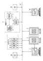
次に、本発明の第2の実施形態に係る医用画像部位認識装置について説明する。図11は、本実施形態に係る医用画像部位認識装置を含む医用画像撮影システムの構成を示すブロック図である。
図11に示すように、このシステムは、図1に示す画像サーバ2の替わりに、画像サーバ5と、画像格納装置6と、部位認識装置7とを含んでいる。これらの装置5〜7は、DICOM規格に準拠している。その他の構成については、図1に示すシステムにおけるものと同様である。
Next, a medical image region recognition apparatus according to the second embodiment of the present invention will be described. FIG. 11 is a block diagram showing a configuration of a medical image photographing system including a medical image region recognition apparatus according to the present embodiment.
As shown in FIG. 11, this system includes an
画像サーバ5は、モダリティ1から出力された画像データを保管及び管理するPACS用サーバである。画像サーバ2は、モダリティ1から入力された画像データを画像格納装置6に格納させる。また、画像サーバ2は、その画像データの画像付帯情報に撮像部位を表す情報((0018,0015):Body Part)が含まれていない場合に、画像データを部位認識装置7に出力して部位認識処理を行わせる。さらに、画像サーバ2は、情報読影用端末4の要求に従って、画像格納装置6に格納されている画像データを画像表示端末3に出力するように、画像格納装置6を制御する。
The
画像格納装置6は、例えば、画像サーバ5に接続されているハードディスクドライブである。或いは、記録媒体として、その他に、MO、MT、RAM、CD−ROM、又は、DVD−ROM等を用いても良く、その場合には、それらの記録媒体を駆動する駆動装置が、画像サーバ5に接続される。或いは、画像サーバ5に画像格納装置を内蔵させても良い。
The
医用画像部位認識装置(以下において、単に「部位認識装置」という)7は、1シリーズの画像データによって表される複数の軸位断画像に基づいて、各軸位断画像に被検体のどの部位が撮像されているかを認識して部位情報を生成する装置である。部位認識装置7は、例えば、パーソナルコンピュータ(PC)によって構成されている。また、部位認識装置7における部位認識処理機能及び動作については、図1及び図2に示す部位認識部12におけるものと同様である。
A medical image region recognition device (hereinafter, simply referred to as “region recognition device”) 7 is based on a plurality of axial position discontinuity images represented by one series of image data. This is a device that recognizes whether or not an image is captured and generates part information. The
本実施形態においては、部位認識装置7をPCによって構成するので、既存の医用画像撮影システムに部位認識処理機能を容易に組み込むことができる。従って、既存の設備を活用しつつ、効率の良い部位認識処理を行うことが可能となる。
なお、本実施形態において、部位認識装置7は、生成された部位情報を出力して画像格納装置6に格納させているが、部位認識装置7に内蔵されている格納装置(例えば、ハードディスク)に部位情報を格納するようにしても良い。
In the present embodiment, since the
In the present embodiment, the
以上説明した第1及び第2の実施形態において、部位認識部12(図1)及び部位認識装置7(図11)は、モダリティ1から直接画像サーバ2及び5に入力された画像データについて部位認識処理を行っている。しかしながら、モダリティ1において生成された後で一旦記録媒体に格納された画像データを画像サーバ2又は部位認識装置7に読み込むことにより、部位認識処理を行っても良い。
In the first and second embodiments described above, the part recognizing unit 12 (FIG. 1) and the part recognizing apparatus 7 (FIG. 11) recognize the part of the image data directly input from the modality 1 to the
次に、本発明の第1及び第2の実施形態に係る医用画像部位認識装置を含む医用画像撮影システムの別の構成例について、図12を参照しながら説明する。図12に示すように、このシステムにおいて、モダリティ1、画像サーバ2、画像表示端末3、読影用端末4は、LAN(ローカル・エリア・ネットワーク)等のネットワークN1を介して互いに接続されている。或いは、画像サーバ2の替わりに、図11に示す画像サーバ5、画像格納装置6、及び、部位認識装置7を、ネットワークN1に接続するようにしても良い。また、このネットワークN1に、各診療科に設置されている端末30や、RIS(radiology information system:放射線科情報管理システム)40や、HIS(Hospital Information System:病院情報システム)50を接続しても良い。
Next, another configuration example of the medical image photographing system including the medical image region recognition apparatus according to the first and second embodiments of the present invention will be described with reference to FIG. As shown in FIG. 12, in this system, the modality 1, the
図12に示すように、医用画像部位認識機能を有する画像サーバ2(又は、部位認識装置7)をネットワークN1に接続することにより、部位認識された画像データを種々の端末(例えば、読影用端末4や、各診療科端末30)において利用できるようになるので、効率の良い医療診断を行うことが可能となる。 As shown in FIG. 12, by connecting an image server 2 (or site recognition device 7) having a medical image site recognition function to a network N1, site-recognized image data is transmitted to various terminals (for example, an interpretation terminal). 4 and each clinical department terminal 30), it is possible to perform an efficient medical diagnosis.
本発明は、医療用撮像モダリティによって取得された画像データに基づいて、医用画像に表されている体部の部位認識を行う医用画像部位認識装置、及び、そのような装置において用いられる医用画像部位認識プログラムにおいて利用することが可能である。 The present invention relates to a medical image region recognition device for recognizing a region of a body part represented in a medical image based on image data acquired by a medical imaging modality, and a medical image region used in such a device. It can be used in a recognition program.
1 モダリティ
1a コンピュータ断層撮影(CT)装置
1b コンピュータ放射線撮影(CR)装置
1c 磁気共鳴撮像(MRI)装置
1d ポジトロン断層撮影(PET)装置
1e 超音波撮像(US)装置
2、5 画像サーバ
3 画像表示端末
3a、4a 画面
4 読影用端末
4b 入力デバイス
6 画像格納装置
7 部位認識装置
11 制御部
12 部位認識部
13 格納部
21 特徴量計算部
22 部位確信度計算部
22a スコアテーブル記憶部
23 部位決定処理部
24 部位情報記憶部
25 部位修正処理部
30 診療科端末
40 放射線科情報管理システム(RIS)
50 病院情報システム(HIS)
DESCRIPTION OF SYMBOLS 1
50 Hospital Information System (HIS)
Claims (18)
各軸位断画像に表された体部の部位を暫定的に決定する部位決定手段と、
複数の軸位断画像に関する情報に基づいて、前記部位決定手段により少なくとも1つの軸位断画像について暫定的に決定された部位を修正する部位修正手段と、
を具備する医用画像部位認識装置。 An apparatus for recognizing a part of a body part represented in each of a plurality of axial dislocation images based on image data representing a series of axial discontinuity images obtained by imaging and inspecting a subject,
A part determining means for tentatively determining a part of the body part represented in each axial position discontinuity image;
A part correcting unit that corrects a part temporarily determined for at least one axial position discontinuity image by the part determining unit based on information on a plurality of axial position discontinuity images;
A medical image region recognition apparatus comprising:
各軸位断画像に表された体部の部位を暫定的に決定する手順(a)と、
複数の軸位断画像に関する情報に基づいて、手順(a)において少なくとも1つの軸位断画像について暫定的に決定された部位を修正する手順(b)と、
をCPUに実行させる医用画像部位認識プログラム。 A program used in an apparatus for recognizing a part of a body part represented in each of a plurality of axial dislocation images based on image data representing a series of axial discontinuity images obtained by imaging and inspecting a subject Because
A procedure (a) for tentatively determining a body part represented in each axial discontinuity image;
A procedure (b) for correcting a portion tentatively determined for at least one axial dislocation image in the procedure (a) based on information on a plurality of axial dislocation images;
A medical image region recognition program for causing a CPU to execute
When the subject is a human body, the region includes a head, a neck, a chest, an abdomen, a pelvis, a leg, a boundary region between these regions, or a plurality of regions within them. The medical image region recognition program according to any one of claims 10 to 17, including two or more of overlapping regions.
Priority Applications (2)
| Application Number | Priority Date | Filing Date | Title |
|---|---|---|---|
| JP2006140041A JP4855141B2 (en) | 2006-05-19 | 2006-05-19 | Medical image part recognition device and medical image part recognition program |
| US11/798,705 US8194959B2 (en) | 2006-05-19 | 2007-05-16 | Medical image part recognition apparatus and medical image part recognition program |
Applications Claiming Priority (1)
| Application Number | Priority Date | Filing Date | Title |
|---|---|---|---|
| JP2006140041A JP4855141B2 (en) | 2006-05-19 | 2006-05-19 | Medical image part recognition device and medical image part recognition program |
Publications (3)
| Publication Number | Publication Date |
|---|---|
| JP2007307205A true JP2007307205A (en) | 2007-11-29 |
| JP2007307205A5 JP2007307205A5 (en) | 2009-04-09 |
| JP4855141B2 JP4855141B2 (en) | 2012-01-18 |
Family
ID=38712015
Family Applications (1)
| Application Number | Title | Priority Date | Filing Date |
|---|---|---|---|
| JP2006140041A Expired - Fee Related JP4855141B2 (en) | 2006-05-19 | 2006-05-19 | Medical image part recognition device and medical image part recognition program |
Country Status (2)
| Country | Link |
|---|---|
| US (1) | US8194959B2 (en) |
| JP (1) | JP4855141B2 (en) |
Cited By (6)
| Publication number | Priority date | Publication date | Assignee | Title |
|---|---|---|---|---|
| JP2009232981A (en) * | 2008-03-26 | 2009-10-15 | Fujifilm Corp | Image display apparatus and program for the same |
| US7995821B2 (en) | 2008-03-05 | 2011-08-09 | Fujifilm Corporation | Image processing system and image processing method |
| US8150132B2 (en) | 2008-03-17 | 2012-04-03 | Fujifilm Corporation | Image analysis apparatus, image analysis method, and computer-readable recording medium storing image analysis program |
| WO2012073769A1 (en) * | 2010-11-29 | 2012-06-07 | 株式会社 日立メディコ | Image processing device and image processing method |
| JP2020096773A (en) * | 2018-12-19 | 2020-06-25 | 富士フイルム株式会社 | Medical image processor, method and program |
| US11157796B2 (en) | 2017-03-21 | 2021-10-26 | Fujitsu Limited | Joint position estimation device, joint position estimation method, and joint position estimation program |
Families Citing this family (12)
| Publication number | Priority date | Publication date | Assignee | Title |
|---|---|---|---|---|
| JP2008079760A (en) * | 2006-09-27 | 2008-04-10 | Fujifilm Corp | Method and apparatus for image compression processing and medical network system |
| JP5301197B2 (en) * | 2008-04-11 | 2013-09-25 | 富士フイルム株式会社 | Sectional image display apparatus and method, and program |
| JP5355110B2 (en) * | 2009-01-27 | 2013-11-27 | キヤノン株式会社 | Diagnosis support apparatus and diagnosis support method |
| JP5355111B2 (en) * | 2009-01-27 | 2013-11-27 | キヤノン株式会社 | Diagnosis support apparatus and diagnosis support method |
| BRPI1004218A2 (en) * | 2009-03-31 | 2016-02-23 | Fujifilm Corp | image processing device and method, and program |
| JP5534840B2 (en) * | 2010-02-03 | 2014-07-02 | キヤノン株式会社 | Image processing apparatus, image processing method, image processing system, and program |
| JP5905308B2 (en) | 2012-03-26 | 2016-04-20 | 富士フイルム株式会社 | Image processing apparatus, method, and program |
| US9020192B2 (en) | 2012-04-11 | 2015-04-28 | Access Business Group International Llc | Human submental profile measurement |
| US10061979B2 (en) | 2014-09-28 | 2018-08-28 | Koninklijke Philips N.V. | Image processing apparatus and method |
| JP6493884B2 (en) * | 2016-03-09 | 2019-04-03 | 富士フイルム株式会社 | Image display control apparatus and method, and program |
| US10169647B2 (en) | 2016-07-27 | 2019-01-01 | International Business Machines Corporation | Inferring body position in a scan |
| JP7256765B2 (en) * | 2020-02-28 | 2023-04-12 | 株式会社日立製作所 | Medical imaging device, medical image processing device, and image processing program |
Citations (2)
| Publication number | Priority date | Publication date | Assignee | Title |
|---|---|---|---|---|
| JP2003275194A (en) * | 2002-03-25 | 2003-09-30 | Konica Corp | Medical image processing device, medical image processing method, program and recording medium |
| JP2005034473A (en) * | 2003-07-17 | 2005-02-10 | Hitachi Medical Corp | Irregular shadow detecting apparatus |
Family Cites Families (14)
| Publication number | Priority date | Publication date | Assignee | Title |
|---|---|---|---|---|
| US5331550A (en) * | 1991-03-05 | 1994-07-19 | E. I. Du Pont De Nemours And Company | Application of neural networks as an aid in medical diagnosis and general anomaly detection |
| US5926568A (en) * | 1997-06-30 | 1999-07-20 | The University Of North Carolina At Chapel Hill | Image object matching using core analysis and deformable shape loci |
| US7155042B1 (en) * | 1999-04-21 | 2006-12-26 | Auckland Uniservices Limited | Method and system of measuring characteristics of an organ |
| US7167583B1 (en) * | 2000-06-28 | 2007-01-23 | Landrex Technologies Co., Ltd. | Image processing system for use with inspection systems |
| JP4545971B2 (en) | 2001-03-05 | 2010-09-15 | 日本電信電話株式会社 | Medical image identification system, medical image identification processing method, medical image identification program, and recording medium thereof |
| JP3766033B2 (en) | 2001-04-25 | 2006-04-12 | 富士写真フイルム株式会社 | Image processing method, apparatus, and program |
| US6816571B2 (en) * | 2002-02-06 | 2004-11-09 | L-3 Communications Security And Detection Systems Corporation Delaware | Method and apparatus for transmitting information about a target object between a prescanner and a CT scanner |
| US7244230B2 (en) * | 2002-11-08 | 2007-07-17 | Siemens Medical Solutions Usa, Inc. | Computer aided diagnostic assistance for medical imaging |
| JP4447005B2 (en) * | 2003-04-24 | 2010-04-07 | コーニンクレッカ フィリップス エレクトロニクス エヌ ヴィ | Region delineation method and apparatus in computed tomography angiography |
| US6990171B2 (en) * | 2003-10-27 | 2006-01-24 | General Electric Company | System and method of determining a user-defined region-of-interest of an imaging subject for x-ray flux management control |
| US7672491B2 (en) * | 2004-03-23 | 2010-03-02 | Siemens Medical Solutions Usa, Inc. | Systems and methods providing automated decision support and medical imaging |
| US7627154B2 (en) * | 2004-11-23 | 2009-12-01 | Carestream Health, Inc. | Automated radiograph classification using anatomy information |
| US7876938B2 (en) * | 2005-10-06 | 2011-01-25 | Siemens Medical Solutions Usa, Inc. | System and method for whole body landmark detection, segmentation and change quantification in digital images |
| US7983457B2 (en) * | 2005-11-23 | 2011-07-19 | General Electric Company | Method and system for automatically determining regions in a scanned object |
-
2006
- 2006-05-19 JP JP2006140041A patent/JP4855141B2/en not_active Expired - Fee Related
-
2007
- 2007-05-16 US US11/798,705 patent/US8194959B2/en not_active Expired - Fee Related
Patent Citations (2)
| Publication number | Priority date | Publication date | Assignee | Title |
|---|---|---|---|---|
| JP2003275194A (en) * | 2002-03-25 | 2003-09-30 | Konica Corp | Medical image processing device, medical image processing method, program and recording medium |
| JP2005034473A (en) * | 2003-07-17 | 2005-02-10 | Hitachi Medical Corp | Irregular shadow detecting apparatus |
Cited By (8)
| Publication number | Priority date | Publication date | Assignee | Title |
|---|---|---|---|---|
| US7995821B2 (en) | 2008-03-05 | 2011-08-09 | Fujifilm Corporation | Image processing system and image processing method |
| US8150132B2 (en) | 2008-03-17 | 2012-04-03 | Fujifilm Corporation | Image analysis apparatus, image analysis method, and computer-readable recording medium storing image analysis program |
| JP2009232981A (en) * | 2008-03-26 | 2009-10-15 | Fujifilm Corp | Image display apparatus and program for the same |
| WO2012073769A1 (en) * | 2010-11-29 | 2012-06-07 | 株式会社 日立メディコ | Image processing device and image processing method |
| US8958616B2 (en) | 2010-11-29 | 2015-02-17 | Hitachi Medical Corporation | Image processing device and image processing method |
| JP5943353B2 (en) * | 2010-11-29 | 2016-07-05 | 株式会社日立製作所 | Image processing apparatus and image processing method |
| US11157796B2 (en) | 2017-03-21 | 2021-10-26 | Fujitsu Limited | Joint position estimation device, joint position estimation method, and joint position estimation program |
| JP2020096773A (en) * | 2018-12-19 | 2020-06-25 | 富士フイルム株式会社 | Medical image processor, method and program |
Also Published As
| Publication number | Publication date |
|---|---|
| US20070269089A1 (en) | 2007-11-22 |
| US8194959B2 (en) | 2012-06-05 |
| JP4855141B2 (en) | 2012-01-18 |
Similar Documents
| Publication | Publication Date | Title |
|---|---|---|
| JP4855141B2 (en) | Medical image part recognition device and medical image part recognition program | |
| JP4800127B2 (en) | Medical image segmentation device and medical image segmentation program | |
| JP4800129B2 (en) | Medical image display processing apparatus and medical image display processing program | |
| US8334878B2 (en) | Medical image processing apparatus and medical image processing program | |
| US9922268B2 (en) | Image interpretation report creating apparatus and image interpretation report creating system | |
| US8295568B2 (en) | Medical image display processing apparatus and medical image display processing program | |
| US8150132B2 (en) | Image analysis apparatus, image analysis method, and computer-readable recording medium storing image analysis program | |
| US10268802B2 (en) | Medical image processing apparatus and medical image processing system | |
| JP5222082B2 (en) | Information processing apparatus, control method therefor, and data processing system | |
| US20080058611A1 (en) | Medical image processing apparatus | |
| EP3164076B1 (en) | Trachea marking | |
| JP2008259682A (en) | Section recognition result correcting device, method and program | |
| JP6460636B2 (en) | Interpretation report creation device, interpretation report creation system, and interpretation report creation program | |
| JP2009087038A (en) | Image processor and image processing method | |
| JP2013123528A (en) | Image diagnosis support device and image diagnosis support method | |
| JPWO2020110774A1 (en) | Image processing equipment, image processing methods, and programs | |
| JP5539478B2 (en) | Information processing apparatus and information processing method | |
| JP2008006187A (en) | Medical image display processing aparatus and medical image display processing program | |
| JP6258084B2 (en) | Medical image display device, medical image display system, and medical image display program | |
| JP5363962B2 (en) | Diagnosis support system, diagnosis support program, and diagnosis support method | |
| JP2009066060A (en) | Medical image system, finding report generator, finding report generation method, and program | |
| US20220391599A1 (en) | Information saving apparatus, method, and program and analysis record generation apparatus, method, and program | |
| JP2018175695A (en) | Registration apparatus, registration method, and registration program | |
| CN110709888B (en) | Information processing apparatus and method for controlling the same | |
| JP2010220902A (en) | Device, method and program for determination of recognition result |
Legal Events
| Date | Code | Title | Description |
|---|---|---|---|
| A521 | Request for written amendment filed |
Free format text: JAPANESE INTERMEDIATE CODE: A523 Effective date: 20090220 |
|
| A621 | Written request for application examination |
Free format text: JAPANESE INTERMEDIATE CODE: A621 Effective date: 20090220 |
|
| A977 | Report on retrieval |
Free format text: JAPANESE INTERMEDIATE CODE: A971007 Effective date: 20110707 |
|
| A131 | Notification of reasons for refusal |
Free format text: JAPANESE INTERMEDIATE CODE: A131 Effective date: 20110712 |
|
| A521 | Request for written amendment filed |
Free format text: JAPANESE INTERMEDIATE CODE: A523 Effective date: 20110907 |
|
| TRDD | Decision of grant or rejection written | ||
| A01 | Written decision to grant a patent or to grant a registration (utility model) |
Free format text: JAPANESE INTERMEDIATE CODE: A01 Effective date: 20111004 |
|
| A01 | Written decision to grant a patent or to grant a registration (utility model) |
Free format text: JAPANESE INTERMEDIATE CODE: A01 |
|
| A61 | First payment of annual fees (during grant procedure) |
Free format text: JAPANESE INTERMEDIATE CODE: A61 Effective date: 20111026 |
|
| FPAY | Renewal fee payment (event date is renewal date of database) |
Free format text: PAYMENT UNTIL: 20141104 Year of fee payment: 3 |
|
| R150 | Certificate of patent or registration of utility model |
Free format text: JAPANESE INTERMEDIATE CODE: R150 |
|
| R250 | Receipt of annual fees |
Free format text: JAPANESE INTERMEDIATE CODE: R250 |
|
| LAPS | Cancellation because of no payment of annual fees |