JP2007304337A - Video detecting apparatus, video processor, video detecting method, image persistence alleviation method of display apparatus, and video detecting program - Google Patents
Video detecting apparatus, video processor, video detecting method, image persistence alleviation method of display apparatus, and video detecting program Download PDFInfo
- Publication number
- JP2007304337A JP2007304337A JP2006132605A JP2006132605A JP2007304337A JP 2007304337 A JP2007304337 A JP 2007304337A JP 2006132605 A JP2006132605 A JP 2006132605A JP 2006132605 A JP2006132605 A JP 2006132605A JP 2007304337 A JP2007304337 A JP 2007304337A
- Authority
- JP
- Japan
- Prior art keywords
- video
- area
- detection
- determination
- blank
- Prior art date
- Legal status (The legal status is an assumption and is not a legal conclusion. Google has not performed a legal analysis and makes no representation as to the accuracy of the status listed.)
- Abandoned
Links
Images


Classifications
-
- H—ELECTRICITY
- H04—ELECTRIC COMMUNICATION TECHNIQUE
- H04N—PICTORIAL COMMUNICATION, e.g. TELEVISION
- H04N5/00—Details of television systems
- H04N5/44—Receiver circuitry for the reception of television signals according to analogue transmission standards
- H04N5/46—Receiver circuitry for the reception of television signals according to analogue transmission standards for receiving on more than one standard at will
-
- G—PHYSICS
- G09—EDUCATION; CRYPTOGRAPHY; DISPLAY; ADVERTISING; SEALS
- G09G—ARRANGEMENTS OR CIRCUITS FOR CONTROL OF INDICATING DEVICES USING STATIC MEANS TO PRESENT VARIABLE INFORMATION
- G09G5/00—Control arrangements or circuits for visual indicators common to cathode-ray tube indicators and other visual indicators
-
- H—ELECTRICITY
- H04—ELECTRIC COMMUNICATION TECHNIQUE
- H04N—PICTORIAL COMMUNICATION, e.g. TELEVISION
- H04N21/00—Selective content distribution, e.g. interactive television or video on demand [VOD]
- H04N21/40—Client devices specifically adapted for the reception of or interaction with content, e.g. set-top-box [STB]; Operations thereof
- H04N21/43—Processing of content or additional data, e.g. demultiplexing additional data from a digital video stream; Elementary client operations, e.g. monitoring of home network or synchronising decoder's clock; Client middleware
- H04N21/431—Generation of visual interfaces for content selection or interaction; Content or additional data rendering
- H04N21/4318—Generation of visual interfaces for content selection or interaction; Content or additional data rendering by altering the content in the rendering process, e.g. blanking, blurring or masking an image region
-
- G—PHYSICS
- G09—EDUCATION; CRYPTOGRAPHY; DISPLAY; ADVERTISING; SEALS
- G09G—ARRANGEMENTS OR CIRCUITS FOR CONTROL OF INDICATING DEVICES USING STATIC MEANS TO PRESENT VARIABLE INFORMATION
- G09G2310/00—Command of the display device
- G09G2310/02—Addressing, scanning or driving the display screen or processing steps related thereto
- G09G2310/0202—Addressing of scan or signal lines
- G09G2310/0221—Addressing of scan or signal lines with use of split matrices
-
- G—PHYSICS
- G09—EDUCATION; CRYPTOGRAPHY; DISPLAY; ADVERTISING; SEALS
- G09G—ARRANGEMENTS OR CIRCUITS FOR CONTROL OF INDICATING DEVICES USING STATIC MEANS TO PRESENT VARIABLE INFORMATION
- G09G2310/00—Command of the display device
- G09G2310/02—Addressing, scanning or driving the display screen or processing steps related thereto
- G09G2310/0232—Special driving of display border areas
-
- G—PHYSICS
- G09—EDUCATION; CRYPTOGRAPHY; DISPLAY; ADVERTISING; SEALS
- G09G—ARRANGEMENTS OR CIRCUITS FOR CONTROL OF INDICATING DEVICES USING STATIC MEANS TO PRESENT VARIABLE INFORMATION
- G09G2320/00—Control of display operating conditions
- G09G2320/04—Maintaining the quality of display appearance
- G09G2320/043—Preventing or counteracting the effects of ageing
- G09G2320/046—Dealing with screen burn-in prevention or compensation of the effects thereof
-
- G—PHYSICS
- G09—EDUCATION; CRYPTOGRAPHY; DISPLAY; ADVERTISING; SEALS
- G09G—ARRANGEMENTS OR CIRCUITS FOR CONTROL OF INDICATING DEVICES USING STATIC MEANS TO PRESENT VARIABLE INFORMATION
- G09G2340/00—Aspects of display data processing
- G09G2340/04—Changes in size, position or resolution of an image
- G09G2340/0407—Resolution change, inclusive of the use of different resolutions for different screen areas
- G09G2340/0414—Vertical resolution change
-
- H—ELECTRICITY
- H04—ELECTRIC COMMUNICATION TECHNIQUE
- H04N—PICTORIAL COMMUNICATION, e.g. TELEVISION
- H04N21/00—Selective content distribution, e.g. interactive television or video on demand [VOD]
- H04N21/40—Client devices specifically adapted for the reception of or interaction with content, e.g. set-top-box [STB]; Operations thereof
- H04N21/43—Processing of content or additional data, e.g. demultiplexing additional data from a digital video stream; Elementary client operations, e.g. monitoring of home network or synchronising decoder's clock; Client middleware
- H04N21/431—Generation of visual interfaces for content selection or interaction; Content or additional data rendering
- H04N21/4312—Generation of visual interfaces for content selection or interaction; Content or additional data rendering involving specific graphical features, e.g. screen layout, special fonts or colors, blinking icons, highlights or animations
- H04N21/4316—Generation of visual interfaces for content selection or interaction; Content or additional data rendering involving specific graphical features, e.g. screen layout, special fonts or colors, blinking icons, highlights or animations for displaying supplemental content in a region of the screen, e.g. an advertisement in a separate window
-
- H—ELECTRICITY
- H04—ELECTRIC COMMUNICATION TECHNIQUE
- H04N—PICTORIAL COMMUNICATION, e.g. TELEVISION
- H04N7/00—Television systems
- H04N7/01—Conversion of standards, e.g. involving analogue television standards or digital television standards processed at pixel level
- H04N7/0117—Conversion of standards, e.g. involving analogue television standards or digital television standards processed at pixel level involving conversion of the spatial resolution of the incoming video signal
- H04N7/0122—Conversion of standards, e.g. involving analogue television standards or digital television standards processed at pixel level involving conversion of the spatial resolution of the incoming video signal the input and the output signals having different aspect ratios
Landscapes
- Engineering & Computer Science (AREA)
- Multimedia (AREA)
- Signal Processing (AREA)
- Physics & Mathematics (AREA)
- Computer Hardware Design (AREA)
- General Physics & Mathematics (AREA)
- Theoretical Computer Science (AREA)
- Controls And Circuits For Display Device (AREA)
- Transforming Electric Information Into Light Information (AREA)
- Control Of Indicators Other Than Cathode Ray Tubes (AREA)
- Electroluminescent Light Sources (AREA)
- Image Processing (AREA)
Abstract
Description
本発明は、表示画面と映像のアスペクト比が異なる際に映像以外の領域に現れるブランク領域の検出を行う映像検出装置、映像検出方法、表示装置の焼き付き軽減方法および映像検出プログラムに関する。 The present invention relates to a video detection device, a video detection method, a display burn-in reduction method, and a video detection program for detecting a blank area that appears in a region other than a video when the aspect ratio of the display screen and the video is different.
従来、例えばテレビジョン受像機などにおいて、その画面にアスペクト比が異なる映像を表示する場合、映像の無い余白部分には黒色または所定の模様の帯状の領域(マスク)が画面上に発生する。このような領域は長時間同じ色又は模様などが表示されるためこの領域が表示される画面は焼き付きが発生しやすくなり、その焼き付きがユーザに視認され表示品質上の問題となっていた。このような焼き付きを低減させるために、特許文献1に記載の映像表示装置が提案されている。特許文献1に記載の映像表示装置は、画面の上下または左右に黒色の帯が存在するか否かを黒検出手段で検出し、検出した黒色の帯をマスク信号レベル発生器で別の色などを発生させ置き換えている。
特許文献1の映像表示装置は黒色のマスク領域しか検出できないため、デジタル放送などで見られる柄模様などの黒色以外のマスク領域は検出できなかった。したがって、黒色以外のマスク領域において焼き付きを低減させることができなかった。
Since the video display device of
そこで、本発明は、例えば画面にアスペクト比が異なる映像を表示することがある場合に映像領域と映像領域以外の領域(ブランク領域)とを有する映像の映像領域以外の領域(ブランク領域)を精度良く検出できる映像検出装置、映像処理装置、映像検出方法、表示装置の焼き付き軽減方法および映像検出プログラムを提供することを課題とする。 Therefore, the present invention, for example, when an image having a different aspect ratio is displayed on the screen, the region other than the image region (blank region) of the image having the image region and the region other than the image region (blank region) is accurate. It is an object of the present invention to provide a video detection device, a video processing device, a video detection method, a burn-in reduction method for a display device, and a video detection program that can be detected well.
上記課題を解決するために、請求項1記載の発明は、入力される映像領域と該映像領域以外の領域に位置するブランク領域とを有する映像の前記ブランク領域の検出を行う映像検出装置において、前記映像の任意の走査方向の輝度レベルの変化に基づいて前記ブランク領域を検出する第1の検出手段と、前記映像に予め複数の判定領域を設定し、前記複数の判定領域が夫々動画か静止画かの判定に基づいて前記ブランク領域を検出する第2の検出手段と、前記第1の検出手段および第2の検出手段の検出結果に基づいて前記ブランク領域を検出したか否かの判定を行う判定手段と、を備えたことを特徴としている。
In order to solve the above-mentioned problem, the invention according to
請求項8記載の発明は、入力される映像領域と該映像領域以外の領域に位置するブランク領域とを有する映像の前記ブランク領域の検出を行う映像検出方法において、前記映像の任意の走査方向の輝度レベルの変化に基づいて前記ブランク領域を検出し、前記映像に予め複数の判定領域を設定して前記複数の判定領域が夫々動画か静止画かの判定に基づいて前記ブランク領域を検出して、前記走査方向の輝度レベルの変化および前記複数の判定領域が夫々動画か静止画かの判定による検出の双方の検出結果に基づいて前記ブランク領域を検出したか否かの判定を行うことを特徴としている。
The invention according to
請求項9に記載の発明は、夫々所定範囲にブランク領域と映像領域を有する映像を表示する表示装置の焼き付き軽減方法であって、入力映像の前記ブランク領域に対応する範囲に位置する映像の輝度レベルと、前記映像領域に対応する範囲に位置する映像の輝度レベルの差が所定値以上であり、かつ、前記入力映像において、前記ブランク領域に対応する範囲に位置する映像が静止画であり、かつ、前記映像領域に対応する範囲に位置する映像が動画である場合に、前記ブランク領域に対応する範囲に位置する映像がブランク領域であると判定し、該判定に基づいて、入力映像に対して焼き付き軽減処理を行うことを特徴としている。
The invention according to
請求項10に記載の発明は、入力される映像領域と該映像領域以外の領域に位置するブランク領域とを有する映像の前記ブランク領域の検出を行う映像検出装置のコンピュータを動作させるための映像検出プログラムにおいて、前記映像の任意の走査方向の輝度レベルの変化に基づいて前記ブランク領域を検出する第1の検出手段と、前記映像に予め複数の判定領域を設定し、前記複数の判定領域が夫々動画か静止画かの判定に基づいて前記ブランク領域を検出する第2の検出手段と、前記第1の検出手段および第2の検出手段の検出結果に基づいて前記ブランク領域を検出したか否かの判定を行う判定手段としてコンピュータに機能させることを特徴としている。 According to a tenth aspect of the present invention, there is provided a video detection for operating a computer of a video detection device that detects the blank area of a video having an input video area and a blank area located outside the video area. In the program, a first detection unit that detects the blank area based on a change in luminance level in an arbitrary scanning direction of the video, and a plurality of determination areas are set in advance in the video, and the plurality of determination areas are respectively set. A second detection means for detecting the blank area based on the determination of whether it is a moving image or a still image; and whether or not the blank area is detected based on detection results of the first detection means and the second detection means It is characterized by making a computer function as a determination means for performing the determination.
以下、本発明の一実施形態にかかる映像検出装置を説明する。本発明の一実施形態にかかる映像検出装置は、映像の任意の走査方向の輝度レベルの変化に基づいてブランク領域を検出する第1の検出手段の結果と、映像内に予め設定した複数の判定領域が動画か静止画かの判定に基づいてブランク領域を検出する第2の検出手段との結果に基づいて、判定手段において入力された映像のブランク領域が検出されたか否かの判定を行う。このようにすることによって、第1の検出手段と第2の検出手段の検出結果を合わせて判定できるので、黒色以外のブランク領域を持つ多様な映像に対して精度良く検出することができる。 Hereinafter, an image detection apparatus according to an embodiment of the present invention will be described. An image detection apparatus according to an embodiment of the present invention includes a result of first detection means for detecting a blank area based on a change in luminance level in an arbitrary scanning direction of an image, and a plurality of determinations set in advance in the image. Based on the result of the second detection means for detecting the blank area based on the determination of whether the area is a moving image or a still image, it is determined whether or not the blank area of the video input by the determination means has been detected. By doing so, the detection results of the first detection means and the second detection means can be determined together, so that various images having blank areas other than black can be accurately detected.
また、第1の検出手段が、走査方向の複数ラインにおいて輝度レベルが予め設定した所定値以上の変化をした画素を映像領域とブランク領域との境界と検出することによってブランク領域を検出してもよい。このようにすることにより、映像領域とブランク領域との輝度差が所定値以上ある場合には確実に検出することができる。 The first detection unit may detect a blank area by detecting a pixel whose luminance level has changed in a plurality of lines in the scanning direction by a predetermined value or more as a boundary between the video area and the blank area. Good. In this way, when the luminance difference between the video area and the blank area is greater than or equal to a predetermined value, it can be reliably detected.
また、第1の検出手段が、検出した映像領域とブランク領域との境界を記憶する境界記憶手段を備え、境界記憶手段に記憶させた過去の境界の位置と現在検出した境界の位置との差が第1の許容値未満であると検出したことによってブランク領域を検出してもよい。このようにすることにより、映像領域とブランク領域との境界は時間的に位置が異なることがほとんどないので、フィールド間の差が第1の許容値未満とすることで第1の検出手段の精度を高くすることができる。 The first detection means includes boundary storage means for storing the boundary between the detected video area and the blank area, and the difference between the past boundary position stored in the boundary storage means and the currently detected boundary position is provided. The blank area may be detected by detecting that is less than the first allowable value. By doing this, the position of the boundary between the video area and the blank area is hardly different in time, so that the accuracy of the first detection means can be reduced by setting the difference between fields to be less than the first allowable value. Can be high.
また、境界を検出するために予め設定する走査方向の複数のラインが、互いに間隔を空けて設定されていてもよい。このようにすることにより、映像領域とブランク領域との境界線が走査方向に対して鉛直であることが検出できるので、ブランク領域ではない低輝度な領域による誤判定を少なくすることができる。 In addition, a plurality of lines in the scanning direction that are set in advance to detect the boundary may be set at intervals. By doing so, it is possible to detect that the boundary line between the video area and the blank area is vertical with respect to the scanning direction, so that it is possible to reduce erroneous determination due to a low-luminance area that is not the blank area.
また、第2の検出手段が、予め設定した複数の判定領域の信号レベルを所定時間分記憶する信号レベル記憶手段を備え、信号レベル記憶手段に記憶した複数の判定領域のうちブランク領域の位置に設定された判定領域において所定時間信号レベルの変化がなく、かつ予め映像領域に設定された判定領域において信号レベルが変化したことによって前記ブランク領域を検出してもよい。このようにすることにより、ブランク領域は時間経過によって平均輝度レベルが変化することはなく、映像領域は時間経過によって映像が変化すれば平均輝度レベルも変化するのでブランク領域を精度良く検出することができる。 The second detection means includes signal level storage means for storing a predetermined number of signal levels in a plurality of determination areas for a predetermined time, and is located at a blank area position among the plurality of determination areas stored in the signal level storage means. The blank area may be detected when there is no change in the signal level for a predetermined time in the set determination area and the signal level is changed in the determination area set in advance in the video area. In this way, the average luminance level of the blank area does not change with the passage of time, and the average luminance level of the video area also changes when the image changes with the passage of time, so that the blank area can be detected with high accuracy. it can.
また、第2の検出手段が、予め設定する複数の判定領域は、ブランク領域1箇所につき複数設け、かつ映像領域に複数設けてもよい。このようにすることにより、領域を細かく分割することができるので、第2の検出手段の検出精度を高くすることができる。 In addition, a plurality of determination areas set in advance by the second detection unit may be provided for each blank area and may be provided for a video area. By doing so, the region can be finely divided, so that the detection accuracy of the second detection means can be increased.
また、請求項1乃至6のいずれかに記載の映像検出装置を、該映像検出装置の検出結果に応じて入力された映像に加工を施す加工手段を備える映像処理装置に備えてもよい。このようにすることにより、映像検出装置において、ブランク領域を検出した際にブランク領域に焼き付きが生じにくくなるような加工処置を施すことが可能となる。
In addition, the video detection device according to any one of
また、本発明の一実施形態にかかる映像調整方法は、映像の走査方向の輝度レベルの変化に基づいてブランク領域を検出し、映像内に予め設定した複数の判定領域が動画か静止画かの判定に基づいてブランク領域を検出して、これら2つの検出結果に基づいてブランク領域が検出されたか否かの判定を行う。このようにすることによって、2つの異なる検出方法の検出結果を合わせて判定できるので、黒色以外のブランク領域を持つ多様な映像に対しても精度良く検出することができる。 The image adjustment method according to an embodiment of the present invention detects a blank area based on a change in luminance level in the scanning direction of an image, and determines whether a plurality of determination areas set in the image are moving images or still images. A blank area is detected based on the determination, and it is determined whether a blank area is detected based on these two detection results. In this way, the detection results of two different detection methods can be determined together, so that various images having blank areas other than black can be detected with high accuracy.
また、本発明の一実施形態にかかる表示装置の焼き付き軽減方法は、入力映像のブランク領域に対応する範囲に位置する映像の輝度レベルと、映像領域に対応する範囲に位置する映像の輝度レベルの差が所定値以上であり、かつ、入力映像において、ブランク領域に対応する範囲に位置する映像が静止画であり、かつ、映像領域に対応する範囲に位置する映像が動画である場合に、ブランク領域の映像がブランク領域であると判定し、その判定に基づいて入力映像に対して焼き付き軽減処理を行う。このようにすることによって、複数の異なる検出方法の検出結果を合わせてブランク領域を判定した結果を基に焼き付きの軽減処理を行えるので、ブランク領域の誤判定が少なくなり焼き付きの軽減処理を確実に行うことができる。 Also, a burn-in reduction method for a display device according to an embodiment of the present invention includes a luminance level of a video located in a range corresponding to a blank area of an input video and a luminance level of a video located in a range corresponding to the video area. Blank when the difference is greater than or equal to a predetermined value, and the input video is a still image and the video located in the range corresponding to the video region is a moving image. It is determined that the video in the area is a blank area, and burn-in reduction processing is performed on the input video based on the determination. By doing so, burn-in reduction processing can be performed based on the result of determining the blank area by combining the detection results of a plurality of different detection methods, so that erroneous determination of the blank area is reduced and burn-in reduction processing is ensured. It can be carried out.
また、本発明の一実施形態にかかる映像処理プログラムは、映像の走査方向の輝度レベルの変化に基づいてブランク領域を検出する第1の検出手段の結果と、映像内に予め設定した複数の判定領域が動画か静止画かの判定に基づいてブランク領域を検出する第2の検出手段との結果に基づいて、判定手段においてブランク領域を検出したか否かの判定を行う。このようにすることによって、第1の検出手段と第2の検出手段の検出結果を合わせて判定できるので、黒色以外のブランク領域を持つ多様な映像に対して精度良く検出することができる。 The video processing program according to an embodiment of the present invention includes a result of the first detection unit that detects a blank area based on a change in luminance level in the scanning direction of the video, and a plurality of determinations set in advance in the video. Based on the result of the second detection unit detecting the blank region based on the determination of whether the region is a moving image or a still image, it is determined whether or not the blank region is detected by the determination unit. By doing so, the detection results of the first detection means and the second detection means can be determined together, so that various images having blank areas other than black can be accurately detected.
本発明の第1の実施例にかかる映像検出装置を備えた映像処理装置1を図1ないし図7を参照して説明する。映像処理装置1は図1に示すように映像入力端子2と、映像検出装置としてのマスク検出部3と、マスク合成部4と、モニタ5と、を備えている。
A
マスク検出部3は、第1の検出手段としてのアクティブ検出部3a、第2の検出手段としてのレベル検出部3bと、判定手段としての論理和3cとを備え、画像入力端子2から入力される映像信号に対して、4:3のアスペクト比の映像を16:9のアスペクト比で放送または再生などを行った際に映像領域以外の領域に発生するブランク領域(以降サイドマスクと呼称する)の検出を行う。
The
アクティブ検出部3aは、映像の走査方向のラインとしての走査線の画素値のレベル変化からサイドマスクと映像領域との境界を検出してサイドマスクの検出を行う。また、アクティブ検出部3aは境界の位置を所定のフィールド分記憶する境界記憶手段としての図示しないRAM(Random Access Memory)を内蔵している。レベル検出部3bは、16:9のアスペクト比のサイドマスクと映像領域に夫々判定領域を設定して各判定領域に所定時間動きがあるか静止しているかを判定することでサイドマスクの検出を行う。また、レベル検出部3bも各判定領域が動画か静止画かの判定を行うために所定時間分の各領域の平均輝度レベルを記憶するためのレベル記憶手段としての図示しないRAMを内蔵している。論理和3cはアクティブ検出部3aの結果とレベル検出部3bの結果の論理和をとってマスク合成部4に出力する。すなわち、アクティブ検出部3aとレベル検出部3bのいずれかがサイドマスクを検出すればサイドマスクが検出されたと判定され判定結果がマスク合成部4に出力される。
The active detection unit 3a detects the side mask by detecting the boundary between the side mask and the video region from the level change of the pixel value of the scanning line as a line in the video scanning direction. The active detection unit 3a has a RAM (Random Access Memory) (not shown) as boundary storage means for storing a boundary position for a predetermined field. The
加工手段(焼き付き軽減処理)としてのマスク合成部4は、映像入力端子2から入力された映像に対して、マスク検出部3からの検出結果に基づいて焼き付きの起りにくい(あるいは目立たなくする)サイドマスク(一定以上の輝度レベルがある均一なパターン)として例えばグレーのサイドマスクを合成し合成後の映像をモニタ5へ出力する。
The
表示装置としてのモニタ5は、CRT(Cathode Ray Tube)、PDP(Plasma Display Panel)などにより構成され、マスク合成部4から入力される映像を表示する。
The
つぎに、マスク検出部3における具体的な映像領域とサイドマスクとを有する映像の検出方法について説明する。
Next, a method for detecting an image having a specific image area and a side mask in the
まず、アクティブ検出部3aの動作を図2ないし図5を参照して説明する。図2(a)は本実施例においてアスペクト比4:3の映像をアスペクト比が16:9で放送または再生機器などより再生し映像入力端子2から入力される映像である。図2(a)の映像は水平方向1920画素×垂直方向1080ラインで、画面中央に映像領域としてのアスペクト比4:3の映像が表示され、映像領域以外のアスペクト比4:3の映像の左右にブランク領域としての黒色のサイドマスクが発生している。図2(b)は図2(a)の任意の走査線1ラインの輝度レベルの変化の例を示した図である。図2(b)に示したようにサイドマスクと映像領域では所定値以上の輝度レベルの変化が発生する。したがって映像上に予め設定した走査線1ライン以上から構成される領域Xと、領域Xと間隔を空けて設定した走査線1ライン以上から構成される領域Yの輝度レベルの変化を検出することでサイドマスクの検出を行うことができる。詳細を図3のフローチャートを参照して説明する。
First, the operation of the active detection unit 3a will be described with reference to FIGS. FIG. 2A shows an image input from the
まず、ステップS1において、図2(a)の領域Xおよび領域Yにおける映像領域の走査方向としての水平方向の開始位置と終了位置を取得してステップS2へ進む。開始位置および終了位置は、走査線1ライン1920画素において左端の画素を1、右端の画素を1920としたときの画素の座標で示す。開始位置は前述したように輝度レベルの所定値以上の変化を検出した座標を開始位置として取得する。終了位置も同様に輝度レベルの所定値以上の変化を検出した座標を終了位置として取得する。すなわち、開始位置および終了位置が映像領域とサイドマスクとの境界を表す座標となる。また、所定値とはサイドマスクと映像領域との境界であると検出できる程度の輝度レベルの差である。
First, in step S1, the horizontal start position and end position as the scanning direction of the video area in the area X and area Y of FIG. 2A are acquired, and the process proceeds to step S2. The start position and end position are indicated by the coordinates of a pixel when the leftmost pixel is 1 and the rightmost pixel is 1920 in the
次に、ステップS2において、ステップS1で取得した領域Xおよび領域Yの開始位置と終了位置と、RAMに記憶されている前回の領域Xおよび領域Yの開始位置と終了位置との差分絶対値を、領域Xの開始位置、領域Xの終了位置、領域Yの開始位置、領域Yの終了位置夫々に対して算出しステップS3に進む。前回の領域Xおよび領域Yの開始位置と終了位置とは、ステップS1実行前に本フローチャートを実行して後述するステップS9で保持された領域Xおよび領域Yの開始位置と終了位置を示す。 Next, in step S2, the absolute difference between the start position and end position of area X and area Y acquired in step S1 and the previous start position and end position of area X and area Y stored in RAM is calculated. Then, calculation is performed for each of the start position of region X, the end position of region X, the start position of region Y, and the end position of region Y, and the process proceeds to step S3. The start position and end position of the previous area X and area Y indicate the start position and end position of area X and area Y held in step S9 described later by executing this flowchart before execution of step S1.
次に、ステップS3において、ステップS1で取得した領域Xおよび領域Yの開始位置がいずれも予め設定した座標Aと座標Bとの間かつ、領域XおよびYの終了位置がいずれも予め設定した座標Cと座標Dとの間に位置しているか否かを判断し、位置している場合(YESの場合)はステップS4に進み、そうでない場合(NOの場合)はステップS8へ進む。座標Aと座標Bおよび座標Cと座標Dはそれぞれアスペクト比16:9の画面にアスペクト比4:3の映像を表示させた際にサイドマスクと映像領域の境界が現れる範囲に設定されている。すなわち、検出した開始位置及び終了位置が映像内の変化でなく映像領域とサイドマスクとの境界によるものか否かの判定を行っている。 Next, in step S3, the start positions of the areas X and Y acquired in step S1 are both between the preset coordinates A and B, and the end positions of the areas X and Y are both preset coordinates. It is determined whether or not it is located between C and coordinates D. If it is located (in the case of YES), the process proceeds to step S4, and if not (in the case of NO), the process proceeds to step S8. The coordinates A and B, the coordinates C and the coordinates D are set so that the boundary between the side mask and the image area appears when an image with an aspect ratio of 4: 3 is displayed on a screen with an aspect ratio of 16: 9. In other words, it is determined whether or not the detected start position and end position are due to the boundary between the video area and the side mask, rather than a change in the video.
次に、ステップS4において、ステップS2で算出した差分絶対値が予め設定した第1の許容値未満か否かを判断して第1の許容値未満の場合(YESの場合)はステップS5へ進み、そうでない場合(NOの場合)はステップS8へ進む。このステップを行うことで開始位置及び終了位置が時間軸方向(フィールド間)でほぼ変化の無いことを判定できる。すなわち、過去に検出した境界の位置と現在に検出した境界の位置との差が予め設定した第1の許容値未満であることを判定している。これは、図4のようにフィールド間で移動するような映像内のオブジェクトをサイドマスクとして誤検出することが無くなるのでサイドマスクの判定精度を高めることができる。なお、第1の許容値としてある程度の幅を持たせているのは、放送局や再生内容などによってサイドマスクと映像の境界位置が数画素程度ずれることがあるためである。また、第1の許容値は開始位置および終了位置夫々別に設定してもよい。 Next, in step S4, it is determined whether or not the absolute difference value calculated in step S2 is less than a preset first allowable value. If it is less than the first allowable value (YES), the process proceeds to step S5. If not (NO), the process proceeds to step S8. By performing this step, it can be determined that the start position and the end position are substantially unchanged in the time axis direction (between fields). That is, it is determined that the difference between the position of the boundary detected in the past and the position of the boundary detected at the present time is less than the first allowable value set in advance. This eliminates erroneous detection of an object in a video that moves between fields as shown in FIG. 4 as a side mask, so that the determination accuracy of the side mask can be improved. The reason why the first allowable value has a certain width is that the boundary position between the side mask and the video image may be shifted by about several pixels depending on the broadcasting station and the content of reproduction. Further, the first allowable value may be set separately for each of the start position and the end position.
次に、ステップS5において、ステップS1で取得した領域Xの開始位置から領域Yの開始位置を差し引いた値の絶対値と、領域Xの終了位置から領域Yの終了位置を差し引いた値の絶対値が予め設定した第2の許容値未満か否かを判断して第2の許容値未満の場合(YESの場合)はステップS6に進み、そうでない場合(NOの場合)はステップS8に進む。このステップを行うことで、領域Xと領域Yとで検出した開始位置及び終了位置がほぼ一致していることを判定できる。これは、図5のように座標Aと座標Bおよび座標Cと座標Dの間を斜めに縦断するような映像に対して、誤検出を無くすことができサイドマスクの判定精度を高めることができる。なお、第2の許容値としてある程度幅を持たせているのは、ノイズ等によって生じる数画素程度の誤差を許容するためである。また、第2の許容値は開始位置および終了位置夫々別に設定してもよい。すわなち、境界を検出するために予め設定する複数のラインが、互いに間隔を空けて設定されていることによってこのような判定が有効となる。 Next, in step S5, the absolute value of the value obtained by subtracting the start position of the region Y from the start position of the region X acquired in step S1, and the absolute value of the value obtained by subtracting the end position of the region Y from the end position of the region X. Is less than the preset second allowable value. If it is less than the second allowable value (in the case of YES), the process proceeds to step S6, and if not (in the case of NO), the process proceeds to step S8. By performing this step, it can be determined that the start position and the end position detected in the region X and the region Y are substantially the same. This eliminates false detection and improves the accuracy of side mask determination for an image in which the coordinates A and B and the coordinates C and D are crossed obliquely as shown in FIG. . The reason why the second tolerance value has a certain range is to allow an error of about several pixels caused by noise or the like. Further, the second allowable value may be set separately for each of the start position and the end position. In other words, such a determination is effective because a plurality of lines set in advance for detecting the boundary are set at intervals.
次に、ステップS6において、ステップS1で取得した開始位置が領域Xおよび領域Yともに立ち上がり(前の座標位置の画素の輝度レベルよりも後の座標位置の画素の輝度レベルが所定レベル以上大きい)かつ、終了位置が立ち下がり(前の座標位置の画素の輝度レベルよりも後の座標位置の画素の輝度レベルが所定レベル以上小さい)または、領域Xおよび領域Yともに立ち下がりかつ、終了位置が立ち上がりか否かを判断し、いずれかに該当する場合(YESの場合)はステップS7に進み、そうでない場合(NOの場合)はステップS8に進む。本ステップでは、立ち上がりと立ち下がりが対になっているか否かの判定を行っている。 Next, in step S6, the start position acquired in step S1 rises in both the region X and the region Y (the luminance level of the pixel at the subsequent coordinate position is higher than the luminance level of the pixel at the previous coordinate position) and Whether the end position falls (the brightness level of the pixel at the coordinate position after the previous coordinate position is lower than the predetermined level by a predetermined level or more), or both the area X and the area Y fall and the end position rises It is determined whether or not, and if any of them is satisfied (in the case of YES), the process proceeds to step S7, and if not (in the case of NO), the process proceeds to step S8. In this step, it is determined whether the rising edge and the falling edge are paired.
次に、ステップS7において、サイドマスクを検出したとし、検出結果を論理和3cへ出力してステップS9へ進む。
Next, assuming that the side mask is detected in step S7, the detection result is output to the
ステップS8においては、サイドマスク未検出(アスペクト比16:9の映像)とし、検出結果を論理和3cに出力してステップS9へ進む。
In step S8, the side mask is not detected (video having an aspect ratio of 16: 9), the detection result is output to the
次に、ステップS9において、これまでのステップにおいて使用した領域Xおよび領域Yの開始位置と終了位置を前回の開始位置および終了位置としてRAMに記憶してステップS1に戻る。 Next, in step S9, the start position and end position of the area X and area Y used in the previous steps are stored in the RAM as the previous start position and end position, and the process returns to step S1.
すなわち、走査方向の1ラインの輝度レベルの変化を検出し、その変化が複数のラインについて発生していることを検出することによってサイドマスクと映像領域との境界を検出することができるので、サイドマスクの検出を行うことができる。また、このアクティブ検出部3aによってサイドマスクと映像領域との輝度差が所定値以上ある場合であれば、サイドマスク領域が黒色でなくても境界を検出することができるのでサイドマスクの検出をすることができる。 In other words, the boundary between the side mask and the video area can be detected by detecting a change in the luminance level of one line in the scanning direction and detecting that the change occurs for a plurality of lines. Mask detection can be performed. Further, if the luminance difference between the side mask and the video area is greater than or equal to a predetermined value by the active detection unit 3a, the boundary can be detected even if the side mask area is not black, so the side mask is detected. be able to.
なお、放送中の時間表示や字幕表示による誤検出を避けるため、領域Xおよび領域Yは夫々画面の上端および下端ではなくある程度画面の中心に寄った位置に設定するのが望ましい。 In order to avoid erroneous detection due to time display or subtitle display during broadcasting, it is desirable to set the region X and the region Y at positions close to the center of the screen to some extent rather than the upper and lower ends of the screen, respectively.
また、上述した実施例では映像領域とサイドマスク領域との境界の差分をフィールド単位で行っていたが、入力される映像がプログレッシブの場合はフレーム単位で映像領域とサイドマスク領域との境界の差分をとる。 In the above-described embodiment, the difference between the boundary between the video area and the side mask area is performed on a field basis. However, if the input video is progressive, the difference between the boundary between the video area and the side mask area on a frame basis. Take.
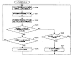
続いて、レベル検出部3bの動作を図6および7を参照して説明する。図6は本実施例においてアスペクト比4:3の映像をアスペクト比が16:9で放送または再生機器より再生し映像入力端子2から入力される映像である。図6の映像は水平方向1920画素×垂直方向1080ラインで、画面中央に映像領域としてのアスペクト比4:3の映像が表示され、映像領域以外のアスペクト比4:3の映像の左右にブランク領域としての黒色のサイドマスクが発生している。レベル検出部3bでは、検出動作を行うためにアスペクト比4:3の映像が入力されたときに左側のサイドマスク領域となる位置に2箇所、右側のサイドマスク領域となる位置に2箇所、アスペクト比4:3映像領域となる位置に4箇所の計8箇所の判定領域を設けている。そして、各判定領域の信号レベルとしての平均輝度レベルの時間方向の変化を検出して、サイドマスク領域内の判定領域(判定領域1〜4)に所定時間変化が無く、かつアスペクト比4:3映像内の判定領域(判定領域5〜8)に変化がある場合はサイドマスクが検出されたと判断する。すなわち、サイドマスクは時間的に変化しないので静止画であり、映像領域は変化する可能性が高いので動画と検出することでサイドマスクの検出を行う。詳細を図7のフローチャートを参照して説明する。
Next, the operation of the
まず、ステップS21において、各判定領域の平均輝度レベルを算出してRAMに記憶しステップS22へ進む。 First, in step S21, the average luminance level of each determination area is calculated and stored in the RAM, and the process proceeds to step S22.
次に、ステップS22において、判定領域毎に前回算出した平均輝度レベルからの変化の有無をRAMに記憶した平均輝度レベルから検出してステップS23に進む。 Next, in step S22, the presence / absence of a change from the previously calculated average luminance level for each determination region is detected from the average luminance level stored in the RAM, and the process proceeds to step S23.
次に、ステップS23において、ステップS22で検出した結果において、判定領域1〜4において平均輝度レベルの変化が無く、かつ判定領域5〜8のいずれかにおいて平均輝度レベルの変化があったか否かを判断して、判定領域1〜4において変化が無く、かつ判定領域5〜8のいずれかにおいて変化があった場合(YESの場合)はステップS24に進み、そうでない場合(NOの場合)はステップS26に進む。すなわち、本ステップでYESの場合は映像領域が動画であることが判定できる。
Next, in step S23, in the result detected in step S22, it is determined whether or not there is no change in the average luminance level in the
次に、ステップS24において、ステップS23において判断した領域1〜4に平均輝度レベルの変化が無いことが予め設定した所定時間継続したか否かを判断し、継続している場合(YESの場合)はステップS25に進み、そうでない場合(NOの場合)はステップS21に戻る。すなわち、本ステップで、YESの場合はサイドマスク領域が静止画であると判定できる。
Next, in step S24, it is determined whether or not there is no change in the average luminance level in the
次に、ステップS25において、サイドマスクを検出したとし、検出結果を論理和3cへ出力してステップS21へ戻る。
Next, assuming that a side mask is detected in step S25, the detection result is output to the
ステップS26においては、判定領域1〜4のいずれかにおいて平均輝度レベルの変化があったか否かを判断し、変化があった場合(YESの場合)はステップS27に進み、そうでない場合(NOの場合)はステップS21に戻る。
In step S26, it is determined whether or not the average luminance level has changed in any of
次に、ステップS27において、サイドマスク未検出(アスペクト比16:9の映像)とし、検出結果を論理和3cに出力してステップS21へ進む。
Next, in step S27, the side mask is not detected (video having an aspect ratio of 16: 9), the detection result is output to the
すなわち、映像をサイドマスクと、映像領域に対して夫々複数の判定領域を設定し、サイドマスクの位置に所定時間平均輝度レベルの変化が無く、映像領域の位置に平均輝度レベルの変化が有ることを検出することで、サイドマスクの検出を行うことができる。また、平均輝度レベルの時間軸方向の変化、すなわちサイドマスクと映像領域とが動画であるか静止画であるかによる検出のため、サイドマスクが黒色でなくとも検出することができる。 That is, the video has a side mask and a plurality of determination areas for the video area, the side mask position has no change in the average brightness level for a predetermined time, and the video area has a change in the average brightness level. By detecting this, the side mask can be detected. In addition, since the detection is based on the change in the average luminance level in the time axis direction, that is, whether the side mask and the video area are moving images or still images, it is possible to detect even if the side mask is not black.
また、判定領域をサイドマスク、映像の各領域で1つでなく、複数に分割することで、判定領域が小さくなることから画面上の狭い領域に限定された輝度変化にも対応できる(例えば、小さな物体の移動や変化も検出できる)ようなる。そして、複数の判定結果に基づいて判定するので、検出の確度を高めることができる。 In addition, by dividing the determination area into a plurality of areas instead of one for each of the side mask and the video, the determination area becomes smaller, so that it is possible to cope with a luminance change limited to a narrow area on the screen (for example, It can also detect movements and changes of small objects). And since it determines based on a some determination result, the accuracy of a detection can be improved.
本実施例によれば、アクティブ検出部3aでラインの輝度レベルの変化からサイドマスク領域と映像領域との境界を検出することでサイドマスクの検出を行い、レベル検出部3bで映像をサイドマスクと、映像領域に対して夫々複数の判定領域を設定し、サイドマスクに設定された判定領域において所定時間平均輝度レベルの変化が無く、かつ映像領域に設定された判定領域において平均輝度レベルの変化が有ることを検出することで、サイドマスクの検出を行い、アクティブ検出部3aとレベル検出部3bの結果の論理和を判定結果としてマスク合成部4に出力しているので、どちらかの検出部がサイドマスクの検出を行えればサイドマスク検出の判定が行えることから、黒色以外のサイドマスクを持つ映像に対しても精度良く検出することができ、マスク合成部4で焼き付きの発生しにくい(あるいは目立たなくする)サイドマスクを合成することでマスク合成部4から出力した映像が表示されるモニタ5において焼き付きが発生しにくくなる。
According to the present embodiment, the active detection unit 3a detects a side mask region by detecting the boundary between the side mask region and the video region from the change in the luminance level of the line, and the
なお、レベル検出部3bにおいて予め設定する判定領域は、本実施例の図6に示すような8箇所でなくてもよい。ただし、映像領域とサイドマスク領域に跨らないように設定する必要がある。すなわち、判定領域はサイドマスクが確実に発生する領域と確実に映像領域になる範囲に設定する必要がある。また、映像領域とサイドマスク領域の全てを網羅するように領域の設定を行わなくてもよい。
In addition, the determination area | region preset in the
次に、本発明の第2の実施例にかかる映像処理装置10を図8および図9を参照して説明する。なお、前述した第1の実施例と同一部分には、同一符号を付して説明を省略する。
Next, a
本実施例は図8に示すように映像検出装置としてのマスク検出部3´において第1の検出手段としてのアクティブ検出部3a´と第2の検出手段としてのレベル検出部3b´とが接続されている点が第1の実施例と異なる。本実施例ではアクティブ検出部3a´において検出したサイドマスクと映像領域との境界位置をレベル検出3b´の判定領域設定に反映させることでレベル検出の精度をより高めるようにしたものである。
In this embodiment, as shown in FIG. 8, an active detection unit 3a ′ as a first detection unit and a
本実施例におけるレベル検出部3b´のフローチャートを図9に示す。図9のフローチャートは図7のフローチャートに対してステップS21の前にステップS28が追加された点が異なる。ステップS28は、アクティブ検出部3a´からのサイドマスクと映像領域との境界位置の情報を取得し、その境界位置情報に応じて判定領域の設定を行う。ただし、映像処理装置1の起動当初やアクティブ検出部3a´が境界位置を検出していない場合は、予め設定されているデフォルトの判定領域で以降のステップを実行する。
FIG. 9 shows a flowchart of the
本実施例によれば、アクティブ検出部3a´でラインの輝度レベルの変化からサイドマスク領域と映像領域との境界を検出することでサイドマスクの検出を行い、レベル検出部3bで映像をサイドマスクと、映像領域に対して夫々複数の判定領域を設定し、サイドマスクに設定された判定領域において所定時間平均輝度レベルの変化が無く、かつ映像領域に設定された判定領域において平均輝度レベルの変化が有ることを検出することで、サイドマスクの検出を行い、アクティブ検出部3a´とレベル検出部3b´の結果の論理和を判定結果としてマスク合成部4に出力しているので、どちらかの検出部がサイドマスクの検出を行えればサイドマスク検出の判定が行えるので、黒色以外のサイドマスクを持つ映像に対しても精度良く検出することができ、マスク合成部4で焼き付きの発生しにくい(あるいは目立たなくする)サイドマスクを合成することでマスク合成部4から出力した映像が表示されるモニタ5において焼き付きが発生しにくくなる。さらに、アクティブ検出部3a´からのサイドマスクと映像領域との境界位置情報を取得してレベル検出部3b´での検出を行うようにしたので、レベル検出部3b´の判定領域がサイドマスクと映像領域との境界付近まで設定できるので検出精度をより高くすることができる。
According to the present embodiment, the active detection unit 3a ′ detects the boundary between the side mask region and the video region from the change in the luminance level of the line, thereby detecting the side mask, and the
次に、本発明の第3の実施例にかかる映像処理プログラムを説明する。なお、前述した第1の実施例と同一部分には、同一符号を付して説明を省略する。 Next, a video processing program according to the third embodiment of the present invention will be described. The same parts as those in the first embodiment described above are denoted by the same reference numerals and description thereof is omitted.
上述した第1の実施例はハードウェアで構成されていたが、本実施例はコンピュータに実行させるプログラムとなっている。図10にフローチャートを示す。 Although the first embodiment described above is configured by hardware, this embodiment is a program to be executed by a computer. FIG. 10 shows a flowchart.
本実施例では図1または図8に示した映像処理装置を図示しないコンピュータのCPU(Central Processing Unit)で置き換え、映像検出装置としてのマスク検出部3または3´やマスク合成部4をCPU上で実行されるプログラムで実現している。したがって、アクティブ検出部3aやレベル検出部3bのフローチャートは前述した第1の実施例および第2の実施例と同様であるので映像検出プログラムを含んだ映像処理プログラムとしての動作のフローチャートを図10を参照して以降説明する。なお、CPUには映像処理プログラムを記憶するROM(Read Only Memory)や各種処理において一時記憶に使用するRAMなどが内蔵されているものとする。
In this embodiment, the video processing apparatus shown in FIG. 1 or FIG. 8 is replaced with a CPU (Central Processing Unit) of a computer (not shown), and the
まず、第1の検出手段としてのステップS41において、アクティブ検出を開始させてステップS42に進む。アクティブ検出が開始されると図3に示したフローチャートが実行される。 First, in step S41 as the first detecting means, active detection is started and the process proceeds to step S42. When the active detection is started, the flowchart shown in FIG. 3 is executed.
次に、第2の検出手段としてのステップS42において、レベル検出を開始させてステップS43に進む。レベル検出が開始されると図7または図9に示したフローチャートが実行される。 Next, in step S42 as the second detection means, level detection is started and the process proceeds to step S43. When level detection is started, the flowchart shown in FIG. 7 or 9 is executed.
次に、判定手段としてのステップS43において、アクティブ検出においてサイドマスクが検出されたか否かを判定し、検出された場合(YESの場合)はステップS45に進み、検出されない場合(NOの場合)はステップS44に進む。 Next, in step S43 as determination means, it is determined whether or not a side mask has been detected in the active detection. If it is detected (in the case of YES), the process proceeds to step S45, and if not detected (in the case of NO). Proceed to step S44.
次に、判定手段としてのステップS44において、レベル検出においてサイドマスクが検出されたか否かを判定し、検出された場合(YESの場合)はステップS45に進み、検出されない場合(NOの場合)はステップS43に戻る。 Next, in step S44 as determination means, it is determined whether or not a side mask is detected in level detection. If it is detected (in the case of YES), the process proceeds to step S45, and if it is not detected (in the case of NO). The process returns to step S43.
次に、加工手段(焼き付き軽減処理)としてのステップS45において、入力された映像に対して、焼き付きの起りにくい(あるいは目立たなくする)サイドマスク(一定以上の輝度レベルがある均一なパターン)として例えばグレーのサイドマスクを合成しモニタ5へ出力する。
Next, in step S45 as processing means (burn-in reduction processing), for example, as a side mask (a uniform pattern having a luminance level higher than a certain level) that is less likely to cause burn-in (or less noticeable) with respect to the input image, for example. A gray side mask is synthesized and output to the
本実施例によれば、アクティブ検出でラインの輝度レベルの変化からサイドマスクと映像領域との境界を検出することでサイドマスクの検出を行い、レベル検出で映像をサイドマスクと、映像領域に対して夫々複数の判定領域を設定し、サイドマスクに設定された判定領域において所定時間平均輝度レベルの変化が無く、かつ映像領域に設定された判定領域において平均輝度レベルの変化が有ることを検出することで、サイドマスクの検出を行い、アクティブ検出とレベル検出の何れかでサイドマスクが検出された場合はマスク合成を行っているので、どちらかの検出部がサイドマスクの検出を行えればサイドマスク検出の判定が行えることから、黒色以外のサイドマスクを持つ映像に対して精度良く検出することができ、マスク合成で焼き付きの発生しにくいサイドマスクを合成することで出力した映像が表示される図示しない表示装置などにおいて焼き付きが発生しにくくなる。さらに、コンピュータプログラムとしたことにより専用のハードウェアが不要となるので汎用性が高まる。 According to this embodiment, the detection of the side mask is performed by detecting the boundary between the side mask and the video area from the change in the luminance level of the line by active detection, and the video is detected from the side mask and the video area by the level detection. A plurality of determination areas are set, and it is detected that there is no change in the average luminance level for a predetermined time in the determination area set in the side mask and there is a change in the average luminance level in the determination area set in the video area. Therefore, if the side mask is detected, and if the side mask is detected by either active detection or level detection, mask synthesis is performed, so if either detector can detect the side mask, the side mask is detected. Since mask detection can be determined, images with side masks other than black can be detected with high accuracy and can be printed by mask synthesis. Kino outputted image is displayed by synthesizing the generated hard side masks burn in such a display device (not shown) it is less likely to occur. Furthermore, since it is a computer program, dedicated hardware is not required, so versatility is enhanced.
なお、上述した実施例では判定手段として論理和3cを用いていたが、論理積としてもよい。すなわち、アクティブ検出とレベル検出のいずれかにおいてサイドマスクが検出されたことで、マスク検出部3におけるサイドマスク検出とするだけでなく、アクティブ検出とレベル検出の双方がサイドマスクを検出することでマスク検出部3におけるサイドマスク検出としてもよい。このようにすることによって、異なる2つの検出方法がともに検出することでサイドマスク検出判定が行えることからサイドマスクの誤検出を少なくすることができる。
In the above-described embodiment, the
また、上述した実施例では加工手段(焼き付き軽減処理)としてマスク合成部4で焼き付きの発生しにくい(あるいは目立たなくする)サイドマスクを合成するようにしていたが、アスペクト比4:3の映像をアスペクト比16:9に引き伸ばす機能(オートワイド機能)やサイドマスクと映像領域の境界のシャープネスを落とす機能で代用しても良い。オードワイド機能は映像領域をサイドマスクまで引き伸ばして表示させることで同じ画面が長時間表示されることを防ぎ、サイドマスクと映像領域の境界のシャープネスを落とす機能は、サイドマスクと映像領域との輝度の差を小さくすることで焼き付きを目立たなくする効果がある。すなわち、モニタ5における焼き付きをユーザなどが視認しにくくなるような処理であればよい。
Further, in the above-described embodiment, as a processing means (burn-in reduction process), the
また、上述した実施例では、ブランク領域が画面の左右に発生する映像に対して説明したが、上下にブランク領域が発生するような場合においても適用することができる。その際は、アクティブ検出は、走査方向が水平走査から垂直走査の方向となり各走査線の所定の座標の画素の輝度レベルの変化から境界を検出する。レベル検出は判定領域の設定位置が変更するのみで基本的な動作は同じである。 In the above-described embodiment, the description has been made on the video in which the blank areas are generated on the left and right sides of the screen. However, the present invention can be applied to the case where the blank areas are generated on the upper and lower sides. In this case, the active detection detects the boundary from the change in the luminance level of the pixel at a predetermined coordinate on each scanning line, with the scanning direction being the horizontal scanning direction to the vertical scanning direction. Level detection is the same as the basic operation except that the setting position of the determination area is changed.
なお、本発明の映像処理装置はCRTやPDPを表示装置として用いるテレビジョン受像機以外にも、モニタディスプレイ(テレビジョンチューナを持たない表示装置)やテレビジョンチューナおよびDVD(Digital Versatile Disk)プレーヤ/レコーダなど表示装置や表示装置に映像を出力する機器に用いることができる。 The video processing apparatus of the present invention is not limited to a television receiver using a CRT or PDP as a display device, but a monitor display (a display device without a television tuner), a television tuner, and a DVD (Digital Versatile Disk) player / It can be used for a display device such as a recorder or a device that outputs video to the display device.
前述した実施例によれば、以下の映像検出装置、映像検出方法、表示装置の焼き付き軽減方法および映像検出プログラムが得られる。 According to the above-described embodiment, the following video detection device, video detection method, display burn-in reduction method, and video detection program can be obtained.
(付記1)入力されるアスペクト比4:3の映像領域とサイドマスクとを有する映像のサイドマスクの検出を行うマスク検出部3において、映像の走査線の輝度レベルの変化に基づいてサイドマスクを検出するアクティブ検出部3aと、映像に予め複数の判定領域を設定し、複数の判定領域の平均輝度レベルの変化により夫々の判定領域が動画か静止画かの判定に基づいてサイドマスクを検出するレベル検出部3bと、アクティブ検出部3aおよびレベル検出部3bの検出結果に基づいてサイドマスクを検出したか否かの判定を行う論理和3cと、を備えたことを特徴とするマスク検出部3。
(Additional remark 1) In the
このマスク検出部3によれば、アクティブ検出部3aとレベル検出部3bの検出結果を合わせて判定できるので、黒色以外のサイドマスク領域を持つ多様な映像に対して精度良く検出することができる。
According to this
(付記2)入力されるアスペクト比4:3の映像領域とサイドマスクとを有する映像の前記サイドマスクの検出を行う映像検出方法において、映像の走査線の輝度レベルの変化に基づいてサイドマスクを検出し、映像に予め複数の判定領域を設定して複数の判定領域の平均輝度レベルの変化により夫々の判定領域が動画か静止画かの判定に基づいてサイドマスクを検出して、走査線の輝度レベルの変化および複数の判定領域の所定時間内の平均輝度レベルの変化の双方の検出結果に基づいてサイドマスクを検出したか否かの判定を行うことを特徴とする映像検出方法。 (Supplementary note 2) In a video detection method for detecting the side mask of a video having an input video area having a 4: 3 aspect ratio and a side mask, the side mask is detected based on a change in luminance level of a video scanning line. Detecting, by setting a plurality of determination areas in advance in the video, and detecting a side mask based on the determination of whether each determination area is a moving image or a still image by changing the average luminance level of the plurality of determination areas, A video detection method for determining whether or not a side mask is detected based on detection results of both a change in luminance level and a change in average luminance level within a predetermined time in a plurality of determination areas.
このマスク検出部3によれば、2つの異なる検出方法の検出結果を合わせて判定できるので、黒色以外のサイドマスク領域を持つ多様な映像に対しても精度良く検出することができる。
According to the
(付記3)夫々所定範囲にサイドマスクとアスペクト比4:3の映像領域を有する映像を表示するモニタ5の焼き付き軽減方法であって、入力映像のサイドマスクに対応する範囲に位置する映像の輝度レベルと、アスペクト比4:3の映像領域に対応する範囲に位置する映像の輝度レベルの差が所定値以上であり、かつ、入力映像において、サイドマスクに対応する範囲に位置する映像が静止画であり、かつ、アスペクト比4:3の映像領域に対応する範囲に位置する映像が動画である場合に、サイドマスクに対応する範囲に位置する映像がサイドマスクであると判定し、該判定に基づいて、入力映像に対してグレーのサイドマスクを合成処理することを特徴とするモニタ5の焼き付き軽減方法。
(Supplementary Note 3) A burn-in reduction method for the
この焼き付き軽減方法によれば、2つの異なる検出方法の検出結果を合わせて判定した結果を基にグレーのサイドマスクを合成処理するので、グレーのサイドマスクを合成処理の精度を高くすることができる。 According to this burn-in reduction method, since the gray side mask is synthesized based on the result determined by combining the detection results of the two different detection methods, the accuracy of the gray side mask can be increased. .
(付記4)入力されるアスペクト比4:3の映像領域とサイドマスクとを有する映像のサイドマスクの検出を行う映像検出装置のコンピュータを動作させるための映像検出プログラムにおいて、映像の走査線の輝度レベルの変化に基づいてサイドマスクを検出するステップS41と、映像に予め複数の判定領域を設定し、複数の判定領域の平均輝度レベルの変化により夫々の判定領域が動画か静止画かの判定に基づいてサイドマスクを検出するステップS42と、ステップS41およびステップS42の検出結果に基づいてサイドマスク検出したか否かの判定を行うステップS43およびS44と、としてコンピュータに機能させることを特徴とするコンピュータ読み取り可能な映像検出プログラム。 (Supplementary Note 4) In a video detection program for operating a computer of a video detection device that detects a side mask of a video having an input video area having a 4: 3 aspect ratio and a side mask, the luminance of a video scanning line A step S41 for detecting a side mask based on the level change, and a plurality of determination areas are set in advance in the video, and each determination area is determined to be a moving image or a still image by a change in the average luminance level of the plurality of determination areas. The computer is caused to function as step S42 for detecting the side mask based on the above, and steps S43 and S44 for determining whether or not the side mask is detected based on the detection results of step S41 and step S42. A readable video detection program.
この画像調整方法によれば、ステップS41とステップS42の検出結果を合わせて判定できるので、黒色以外のサイドマスク領域を持つ多様な映像に対して精度良く検出することができる。 According to this image adjustment method, since the detection results of step S41 and step S42 can be determined together, it is possible to accurately detect various images having side mask regions other than black.
なお、前述した実施例は本発明の代表的な形態を示したに過ぎず、本発明は、実施例に限定されるものではない。すなわち、本発明の骨子を逸脱しない範囲で種々変形して実施することができる。 In addition, the Example mentioned above only showed the typical form of this invention, and this invention is not limited to an Example. That is, various modifications can be made without departing from the scope of the present invention.
1 映像処理装置
3 マスク検出部(映像検出装置)
3´ マスク検出部(映像検出装置)
3a アクティブ検出部(第1の検出手段、境界記憶手段)
3a´ アクティブ検出部(第1の検出手段、境界記憶手段)
3b レベル検出部(第2の検出手段、信号レベル記憶手段)
3b´ レベル検出部(第2の検出手段、信号レベル記憶手段)
3c 論理和(判定手段)
4 マスク合成部(加工手段)
5 モニタ(表示装置)
10 映像処理装置
S41 アクティブ検出開始(第1の検出手段)
S42 レベル検出開始(第2の検出手段)
S43 アクティブ検出で検出されたか(判定手段)
S44 レベル検出で検出されたか(判定手段)
S45 マスク合成(加工手段)
1
3 'mask detector (video detector)
3a Active detection unit (first detection means, boundary storage means)
3a ′ active detection unit (first detection means, boundary storage means)
3b Level detector (second detection means, signal level storage means)
3b 'level detection unit (second detection means, signal level storage means)
3c OR (determination means)
4 Mask composition part (processing means)
5 Monitor (display device)
10 Video processing device S41 Active detection start (first detection means)
S42 Level detection start (second detection means)
S43 Was detected by active detection (determination means)
S44 Was detected by level detection (determination means)
S45 Mask composition (processing means)
Claims (10)
前記映像の任意の走査方向の輝度レベルの変化に基づいて前記ブランク領域を検出する第1の検出手段と、
前記映像に予め複数の判定領域を設定し、前記複数の判定領域が夫々動画か静止画かの判定に基づいて前記ブランク領域を検出する第2の検出手段と、
前記第1の検出手段および第2の検出手段の検出結果に基づいて前記ブランク領域を検出したか否かの判定を行う判定手段と、
を備えたことを特徴とする映像検出装置。 In a video detection device for detecting the blank area of a video having an input video area and a blank area located in an area other than the video area,
First detecting means for detecting the blank area based on a change in luminance level in an arbitrary scanning direction of the video;
A plurality of determination areas set in advance in the video, and a second detection means for detecting the blank area based on whether each of the plurality of determination areas is a moving image or a still image;
Determination means for determining whether or not the blank area is detected based on detection results of the first detection means and the second detection means;
A video detection apparatus comprising:
前記映像の任意の走査方向の輝度レベルの変化に基づいて前記ブランク領域を検出し、前記映像に予め複数の判定領域を設定して前記複数の判定領域が夫々動画か静止画かの判定に基づいて前記ブランク領域を検出して、前記走査方向の輝度レベルの変化および前記複数の判定領域が夫々動画か静止画かの判定による検出の双方の検出結果に基づいて前記ブランク領域を検出したか否かの判定を行うことを特徴とする映像検出方法。 In a video detection method for detecting the blank area of a video having an input video area and a blank area located in an area other than the video area,
The blank area is detected based on a change in luminance level in an arbitrary scanning direction of the video, and a plurality of determination areas are set in advance in the video, and the determination areas are determined based on whether each of the determination areas is a moving image or a still image. Whether or not the blank area is detected based on the detection results of both the change in the luminance level in the scanning direction and the detection by determining whether each of the plurality of determination areas is a moving image or a still image. A video detection method characterized by determining whether or not.
入力映像の前記ブランク領域に対応する範囲に位置する映像の輝度レベルと前記映像領域に対応する範囲に位置する映像の輝度レベルの差が所定値以上であり、かつ、前記入力映像において、前記ブランク領域に対応する範囲に位置する映像が静止画であり、かつ、前記映像領域に対応する範囲に位置する映像が動画である場合に、前記ブランク領域に対応する範囲に位置する映像がブランク領域であると判定し、
該判定に基づいて、入力映像に対して焼き付き軽減処理を行うことを特徴とする表示装置の焼き付き軽減方法。 A burn-in reduction method for a display device that displays images each having a blank area and an image area in a predetermined range,
The difference between the luminance level of the video located in the range corresponding to the blank area of the input video and the luminance level of the video located in the range corresponding to the video area is greater than or equal to a predetermined value, and the blank in the input video When the video located in the range corresponding to the area is a still image and the video located in the range corresponding to the video area is a moving image, the video located in the range corresponding to the blank area is a blank area. Judge that there is,
A burn-in reduction method for a display device, wherein burn-in reduction processing is performed on an input video based on the determination.
前記映像の任意の走査方向の輝度レベルの変化に基づいて前記ブランク領域を検出する第1の検出手段と、
前記映像に予め複数の判定領域を設定し、前記複数の判定領域が夫々動画か静止画かの判定に基づいて前記ブランク領域を検出する第2の検出手段と、
前記第1の検出手段および第2の検出手段の検出結果に基づいて前記ブランク領域を検出したか否かの判定を行う判定手段
としてコンピュータに機能させることを特徴とするコンピュータ読み取り可能な映像検出プログラム。 In a video detection program for operating a computer of a video detection device that detects the blank area of a video having an input video area and a blank area located in an area other than the video area,
First detecting means for detecting the blank area based on a change in luminance level in an arbitrary scanning direction of the video;
A plurality of determination areas set in advance in the video, and a second detection means for detecting the blank area based on whether each of the plurality of determination areas is a moving image or a still image;
A computer-readable video detection program that causes a computer to function as a determination unit that determines whether or not the blank area has been detected based on detection results of the first detection unit and the second detection unit. .
Priority Applications (4)
| Application Number | Priority Date | Filing Date | Title |
|---|---|---|---|
| JP2006132605A JP2007304337A (en) | 2006-05-11 | 2006-05-11 | Video detecting apparatus, video processor, video detecting method, image persistence alleviation method of display apparatus, and video detecting program |
| EP07008011A EP1855468A3 (en) | 2006-05-11 | 2007-04-19 | Image detection device, image processing apparatus, image detection method, method of reducing burn-in of display device, and image detection program |
| US11/797,973 US20070263091A1 (en) | 2006-05-11 | 2007-05-09 | Image detection device, image processing apparatus, image detection method, method of reducing burn-in of display device, and image detection program |
| CNA2007101029280A CN101072373A (en) | 2006-05-11 | 2007-05-11 | Image detection device, image processing apparatus, image detection method, method of reducing burn-in of display device, and image detection program |
Applications Claiming Priority (1)
| Application Number | Priority Date | Filing Date | Title |
|---|---|---|---|
| JP2006132605A JP2007304337A (en) | 2006-05-11 | 2006-05-11 | Video detecting apparatus, video processor, video detecting method, image persistence alleviation method of display apparatus, and video detecting program |
Publications (1)
| Publication Number | Publication Date |
|---|---|
| JP2007304337A true JP2007304337A (en) | 2007-11-22 |
Family
ID=38420589
Family Applications (1)
| Application Number | Title | Priority Date | Filing Date |
|---|---|---|---|
| JP2006132605A Abandoned JP2007304337A (en) | 2006-05-11 | 2006-05-11 | Video detecting apparatus, video processor, video detecting method, image persistence alleviation method of display apparatus, and video detecting program |
Country Status (4)
| Country | Link |
|---|---|
| US (1) | US20070263091A1 (en) |
| EP (1) | EP1855468A3 (en) |
| JP (1) | JP2007304337A (en) |
| CN (1) | CN101072373A (en) |
Families Citing this family (9)
| Publication number | Priority date | Publication date | Assignee | Title |
|---|---|---|---|---|
| TWI489873B (en) * | 2008-04-08 | 2015-06-21 | Realtek Semiconductor Corp | Image detecting device and method |
| CN101909143B (en) * | 2009-06-05 | 2013-09-04 | 瑞昱半导体股份有限公司 | Image detection device and method thereof |
| WO2014158203A1 (en) | 2013-03-28 | 2014-10-02 | Intuit Inc. | Method and system for creating optimized images for data identification and extraction |
| WO2015012820A1 (en) * | 2013-07-24 | 2015-01-29 | Intuit Inc. | Method and system for data identification and extraction using pictorial representations in a source document |
| US10079000B2 (en) | 2015-08-12 | 2018-09-18 | Microsoft Technology Licensing, Llc | Reducing display degradation |
| CN106023887B (en) * | 2016-06-16 | 2018-07-10 | 深圳市华星光电技术有限公司 | Reduce the device and method of OLED display panel ghost |
| KR20180072910A (en) | 2016-12-21 | 2018-07-02 | 삼성디스플레이 주식회사 | Display device and driving method thereof |
| CN108093246B (en) * | 2017-11-21 | 2020-04-28 | 青岛海信电器股份有限公司 | Method and device for identifying video playing area of digital set top box |
| KR102478426B1 (en) | 2018-03-16 | 2022-12-16 | 삼성전자주식회사 | Method for detecting black-bar included in video content and electronic device thereof |
Family Cites Families (8)
| Publication number | Priority date | Publication date | Assignee | Title |
|---|---|---|---|---|
| JP3429842B2 (en) * | 1994-04-15 | 2003-07-28 | 松下電器産業株式会社 | Image information detection device for video signal |
| US6262772B1 (en) * | 1998-11-23 | 2001-07-17 | Philips Electronics North America Corporation | Method and apparatus for preventing display screen burn-in |
| JP4920834B2 (en) * | 2000-06-26 | 2012-04-18 | キヤノン株式会社 | Image display device and driving method of image display device |
| JP3995505B2 (en) * | 2002-03-25 | 2007-10-24 | 三洋電機株式会社 | Display method and display device |
| EP1408684A1 (en) * | 2002-10-03 | 2004-04-14 | STMicroelectronics S.A. | Method and system for displaying video with automatic cropping |
| US20050212726A1 (en) * | 2004-03-16 | 2005-09-29 | Pioneer Plasma Display Corporation | Method, display apparatus and burn-in reduction device for reducing burn-in on display device |
| US20050246657A1 (en) * | 2004-05-03 | 2005-11-03 | Widner Steve W | Video display arrangement including image processing circuitry for protecting display and method of protecting a video display |
| KR100594806B1 (en) * | 2004-12-28 | 2006-06-30 | 삼성전자주식회사 | Display apparatus for detecting letter-box boundary and method for image display using the same |
-
2006
- 2006-05-11 JP JP2006132605A patent/JP2007304337A/en not_active Abandoned
-
2007
- 2007-04-19 EP EP07008011A patent/EP1855468A3/en not_active Withdrawn
- 2007-05-09 US US11/797,973 patent/US20070263091A1/en not_active Abandoned
- 2007-05-11 CN CNA2007101029280A patent/CN101072373A/en active Pending
Also Published As
| Publication number | Publication date |
|---|---|
| US20070263091A1 (en) | 2007-11-15 |
| CN101072373A (en) | 2007-11-14 |
| EP1855468A2 (en) | 2007-11-14 |
| EP1855468A3 (en) | 2008-07-09 |
Similar Documents
| Publication | Publication Date | Title |
|---|---|---|
| JP2007304337A (en) | Video detecting apparatus, video processor, video detecting method, image persistence alleviation method of display apparatus, and video detecting program | |
| JP4412323B2 (en) | Video processing apparatus and video display apparatus | |
| US7420617B2 (en) | Image display apparatus | |
| EP1555814A2 (en) | Reducing burn-in associated with mismatched video image/display aspect ratios | |
| JPWO2011033972A1 (en) | Video display device | |
| US20100020104A1 (en) | Display processing device, display processing method, and display processing program | |
| JP4965980B2 (en) | Subtitle detection device | |
| US7822271B2 (en) | Method and apparatus of false color suppression | |
| JP2008011197A (en) | Motion vector detecting device, motion vector detecting method, and interpolation frame generating device | |
| JP2000338947A (en) | Image display control device and burn-in prevention method used therefor and storage medium storing its control program | |
| US8432495B2 (en) | Video processor and video processing method | |
| JPWO2010064319A1 (en) | VIDEO DISPLAY CONTROL DEVICE, VIDEO DISPLAY DEVICE, ITS PROGRAM, AND RECORDING MEDIUM CONTAINING THE PROGRAM | |
| JP2006171425A (en) | Video display apparatus and method | |
| JP2009175182A (en) | Image processing device | |
| JP2008028507A (en) | Image correction circuit, image correction method and image display | |
| JP5188272B2 (en) | Video processing apparatus and video display apparatus | |
| US8345157B2 (en) | Image processing apparatus and image processing method thereof | |
| JP2006154452A (en) | Video signal processor and gradation level difference detection method | |
| JP2009253567A (en) | Television receiver and frame rate conversion method therefor | |
| JP3994519B2 (en) | Display device and image processing method | |
| JP2005203933A (en) | Video-reproducing apparatus and video-reproducing method | |
| JP2011081178A (en) | Video display device | |
| JP2007235300A (en) | Video processing apparatus, and video processing method | |
| US20060044471A1 (en) | Video signal setting device | |
| JPH07298200A (en) | Letter box screen detector |
Legal Events
| Date | Code | Title | Description |
|---|---|---|---|
| A621 | Written request for application examination |
Free format text: JAPANESE INTERMEDIATE CODE: A621 Effective date: 20090413 |
|
| A762 | Written abandonment of application |
Free format text: JAPANESE INTERMEDIATE CODE: A762 Effective date: 20110523 |