JP2007295151A - Pon system and station side apparatus and terminal used for the same - Google Patents
Pon system and station side apparatus and terminal used for the same Download PDFInfo
- Publication number
- JP2007295151A JP2007295151A JP2006118796A JP2006118796A JP2007295151A JP 2007295151 A JP2007295151 A JP 2007295151A JP 2006118796 A JP2006118796 A JP 2006118796A JP 2006118796 A JP2006118796 A JP 2006118796A JP 2007295151 A JP2007295151 A JP 2007295151A
- Authority
- JP
- Japan
- Prior art keywords
- time
- frame
- pon
- terminal device
- side device
- Prior art date
- Legal status (The legal status is an assumption and is not a legal conclusion. Google has not performed a legal analysis and makes no representation as to the accuracy of the status listed.)
- Pending
Links
Images


Classifications
-
- H—ELECTRICITY
- H04—ELECTRIC COMMUNICATION TECHNIQUE
- H04J—MULTIPLEX COMMUNICATION
- H04J3/00—Time-division multiplex systems
- H04J3/02—Details
- H04J3/06—Synchronising arrangements
- H04J3/0635—Clock or time synchronisation in a network
- H04J3/0638—Clock or time synchronisation among nodes; Internode synchronisation
- H04J3/0658—Clock or time synchronisation among packet nodes
- H04J3/0661—Clock or time synchronisation among packet nodes using timestamps
- H04J3/0667—Bidirectional timestamps, e.g. NTP or PTP for compensation of clock drift and for compensation of propagation delays
Abstract
Description
本発明は、局側装置と複数の端末装置の間の通信が時分割多重される、PONシステムとこれに使用する局側装置及び端末装置に関する。 The present invention relates to a PON system in which communication between a station-side device and a plurality of terminal devices is time-division multiplexed, and a station-side device and a terminal device used therefor.
PONシステム(Passive Optical Network System)は、一つの局側装置(OLT:Optical Line Terminal)と複数のユーザ端末装置(ONU:Optical Network Unit)を光カプラ等のパッシブ素子を介して接続されたP2MP(Point To Multipoint)形態の光ファイバネットワークシステムである。このPONシステムのうち、GE−PON(Gigabit Ethernet-PON)は、イーサネット(Ethernet:登録商標)技術をベースとしたギガビットクラスの伝送システムを経済的に実現するもので、IEEE802.3ahTMとして2004年6月に標準化された高速光アクセス方式の一つである。
上記PONシステムでは、局側装置から各端末装置に送信される下り信号については、各端末装置向けの信号を整列させて伝送するTDM(Time Division Multiplexing)方式が採用され、各端末装置から局側装置に送信される上り信号については、互いの信号が衝突しないような正しいタイミングで光信号を送出するTDMA(Time Division Multiple Access)方式が採用されている。このTDMA方式での信号送出のタイミングを正確に行うには、端末装置の時計と局側装置の時計が正確に同期している必要がある。
A PON system (Passive Optical Network System) is a P2MP (P2MP) in which one station side device (OLT: Optical Line Terminal) and a plurality of user terminal devices (ONU: Optical Network Unit) are connected via a passive element such as an optical coupler. Point To Multipoint) type optical fiber network system. Among these PON systems, GE-PON (Gigabit Ethernet-PON) is an economical implementation of a gigabit class transmission system based on Ethernet (registered trademark) technology. It was established as IEEE 802.3ah TM in 2004. This is one of the high-speed optical access methods standardized in June.
In the PON system described above, a TDM (Time Division Multiplexing) method for aligning and transmitting signals for each terminal device is used for the downlink signal transmitted from the station side device to each terminal device. For uplink signals transmitted to the apparatus, a TDMA (Time Division Multiple Access) system is employed in which optical signals are transmitted at correct timing so that the signals do not collide with each other. In order to accurately perform the signal transmission timing in the TDMA system, it is necessary that the clock of the terminal device and the clock of the station side device are accurately synchronized.
このため、例えば上記IEEE802.3ahTMによる標準規格では、局側装置はローカルクロックをカウントして局側装置の時計(以下、PONカウンタという。)を生成すること、PON下り信号の伝送クロックをローカルクロックに同期させること、及び、端末装置に送信するPON制御フレームには送信時点のPONカウンタの値をタイムスタンプ(以下、TSと略記することがある。)として記すことが規定されている。
また、端末装置としては、ローカルクロックをPON受信信号に内包されるクロックに同期させること、ローカルクロックをカウントして端末装置のPONカウンタを生成するとともに、PON制御フレームを受信したときはそのフレームに記されているタイムスタンプの値でPONカウンタを更新すること、送信許可はPONカウンタの値で指示され、端末装置は自身のPONカウンタが指示された範囲にあるときPONに送信すること、このときの伝送クロックをローカルクロックに同期させることが規定されている(非特許文献1参照)。
For this reason, for example, in the standard based on IEEE802.3ah TM , the station side device counts the local clock to generate a clock of the station side device (hereinafter referred to as a PON counter), and the PON downstream signal transmission clock is generated locally. It is specified that the PON control frame transmitted to the terminal device is synchronized with the clock and the value of the PON counter at the time of transmission is described as a time stamp (hereinafter sometimes abbreviated as TS).
Also, as a terminal device, the local clock is synchronized with the clock included in the PON reception signal, the local clock is counted to generate the PON counter of the terminal device, and when the PON control frame is received, Update the PON counter with the indicated time stamp value, transmission permission is indicated by the value of the PON counter, and the terminal device transmits to the PON when its own PON counter is within the specified range, at this time Is synchronized with a local clock (see Non-Patent Document 1).
また、上記標準規格には、往復伝搬時間を求めるレンジング処理に関して、局側装置が端末装置からPON制御フレームを受信したときに、そのPON制御フレームに付されているタイムスタンプと自身のPONカウンタとの差から、当該端末装置との間の往復伝搬時間を求める方法が記載されている。この往復伝搬時間を求めた局側装置は、その往復伝搬時間を勘案して、その後のPON制御フレームを各端末装置に配布するようになっている。 Further, in the above standard, regarding the ranging process for obtaining the round-trip propagation time, when the station side device receives the PON control frame from the terminal device, the time stamp attached to the PON control frame, its own PON counter, Describes a method for obtaining the round-trip propagation time between the terminal device and the terminal device. The station-side device that has obtained the round-trip propagation time considers the round-trip propagation time and distributes the subsequent PON control frame to each terminal device.
一方、PONシステムにおいては今後さらに伝送速度の高速化が予想されるが、かかる高速化の要請に対応するため、タイムスロットごとに異なるレートの信号を生成するマルチレート・バースト回路を付加することにより、端末装置ごとにサービス容量を増加させるようにしたPONシステムにおけるサービス容量の増加方式が知られている(特許文献1参照)。
このように、特定の端末装置に対する伝送速度を高速化する場合でも、既存のサービスを維持したまま新たな高速サービスを導入できるようにして、複数の伝送レートを共存させる必要があり、この場合は、局側装置と各端末装置との通信が異なる複数の伝送レートで行われることになる(以下、マルチレートPONという。)。
On the other hand, in the PON system, it is expected that the transmission speed will be further increased in the future, but in order to respond to such a request for high speed, a multi-rate burst circuit that generates a signal of a different rate for each time slot is added. A service capacity increasing method in a PON system that increases the service capacity for each terminal device is known (see Patent Document 1).
Thus, even when the transmission speed for a specific terminal device is increased, it is necessary to introduce a new high-speed service while maintaining the existing service, and it is necessary to coexist with a plurality of transmission rates. The communication between the station side device and each terminal device is performed at a plurality of different transmission rates (hereinafter referred to as multi-rate PON).
前記標準規格においては、局側装置は下り方向に固定の伝送レートの信号を継続して送出することが前提になっており、端末装置は、その固定レートの下り信号からクロックを再生し、そのクロックに基づいて自身のPONカウンタをインクリメントする。このように、前記標準規格が想定するPONシステムでは、局側装置と端末装置との間でクロックの同期がとられているので、タイムスタンプが到着するインターバルの長短に関係なく、局側装置と端末装置のPONカウンタの同期が正確であることになっている。 The standard is based on the premise that the station side device continuously transmits a signal having a fixed transmission rate in the downlink direction, and the terminal device reproduces a clock from the fixed rate downlink signal, Increment its own PON counter based on the clock. As described above, in the PON system assumed by the standard, since the clock is synchronized between the station side device and the terminal device, the station side device and the station side device can be connected regardless of the length of the interval at which the time stamp arrives. The synchronization of the PON counter of the terminal device is supposed to be accurate.
しかし、例えば前記したマルチレートPONにおいては、下り方向の伝送レートが固定されないことから、下り信号から再生されたクロックでインクリメントされる端末装置のPONカウンタが速くなったり遅くなったりするため、このようなPONカウンタで正確な時刻を表すことができない。
また、マルチレートPONにおいては、端末装置の能力によってはある種の伝送レート(例えば、超高速の10Gの伝送レート)の信号を正しく認識できないことも想定されるが、このような場合に、伝送信号による連続的なクロック同期を前提とする運用は望ましくない。このため、一般に、マルチレートPONにおいては、局側装置と各端末装置のクロックは独立している。もっとも、これらのクロックの理想的な周波数は一致しているが、実際には、規定された範囲内の微小な不一致が避けられない。
However, for example, in the above-described multi-rate PON, since the transmission rate in the downlink direction is not fixed, the PON counter of the terminal device incremented by the clock regenerated from the downlink signal becomes faster or slower. An accurate PON counter cannot represent the exact time.
In multi-rate PON, it may be assumed that a signal of a certain transmission rate (for example, an ultra-high speed 10G transmission rate) cannot be correctly recognized depending on the capability of the terminal device. Operation based on continuous clock synchronization by signals is not desirable. Therefore, in general, in the multi-rate PON, the clocks of the station side device and each terminal device are independent. However, although the ideal frequencies of these clocks match, in reality, a minute mismatch within the specified range is unavoidable.
上記のように、厳密なクロック同期を前提としないマルチレートPONにおいては、端末装置がPON制御フレームを送信するときにそのフレームに付したTSは、その時点の局側装置のPONカウンタの値とは一致しない。
すなわち、局側装置が測定する往復伝搬時間(以下、RTT(Round Trip Time)と略記することがある。)は、局側装置が端末装置からレポートフレーム等PON制御フレームを受信したときのPONカウンタの値(Trと表記)から、当該PON制御フレームのタイムスタンプTSを差し引くことで算出されるが、局側装置と端末装置のクロック同期が厳密に図られていない場合には、タイムスタンプそのものに両装置のクロックの差分が含まれるため、正確な往復伝播時間を算出することができない。
As described above, in a multi-rate PON that does not require strict clock synchronization, when a terminal device transmits a PON control frame, the TS attached to that frame is the value of the PON counter of the station side device at that time. Does not match.
That is, the round trip time measured by the station side device (hereinafter sometimes abbreviated as RTT (Round Trip Time)) is the PON counter when the station side device receives a PON control frame such as a report frame from the terminal device. Is calculated by subtracting the time stamp TS of the PON control frame from the value of Tr (noted as Tr). If the clock synchronization between the station side device and the terminal device is not strictly achieved, the time stamp itself is Since the difference between the clocks of both devices is included, an accurate round-trip propagation time cannot be calculated.
局側装置と端末装置のクロックの周波数差が一定であると仮定した場合、この周波数差に基づく時間的なずれは、端末装置が受信したPON制御フレームのTSで自身のPONカウンタを更新してから、更に局側装置へPON制御フレームを送信するまでの時間によっても変化する。
従って、前記標準規格に従って、RTT=Tr−TSで往復伝播遅延を計算して、それ以降の端末装置の送信許可時間を決定した場合、複数の端末装置間で上り信号が衝突する恐れがあり、また、直前のRTTとの差が一定値を超えた場合には、リンクの切断に至るという恐れもある。
Assuming that the frequency difference between the clocks of the station side device and the terminal device is constant, the time lag based on this frequency difference updates its PON counter with the TS of the PON control frame received by the terminal device. To the time until the PON control frame is further transmitted to the station side device.
Therefore, when the round trip propagation delay is calculated with RTT = Tr-TS according to the standard, and the transmission permission time of the subsequent terminal device is determined, there is a possibility that the uplink signals collide between the plurality of terminal devices, Further, when the difference from the immediately preceding RTT exceeds a certain value, there is a risk that the link will be disconnected.
本発明は、このような実情に鑑み、往復伝搬時間を勘案したPON制御フレームを局側装置が各端末装置に配布するPONシステムにおいて、両装置間のクロック同期を前提としなくても、各端末装置からの上り信号を衝突させずに配置できるようにすることを第一の目的とする。
また、本発明は、往復伝搬時間を勘案したPON制御フレームを局側装置が各端末装置に配布するPONシステムにおいて、両装置間のクロック同期を前提としなくても、往復伝搬時間を正確に求め、各端末装置からの上り信号を衝突させずに効率よく配置できるようにすることを第二の目的とする。
さらに、本発明は、往復伝搬時間を勘案したPON制御フレームを局側装置が各端末装置に配布するPONシステムにおいて、両装置間のクロック周波数の差を測定し、各端末装置からの上り信号を衝突させずにさらに効率よく配置できるようにすることを第三の目的とする。
In the PON system in which the station side device distributes the PON control frame in consideration of the round trip propagation time to each terminal device in view of such a situation, even if the clock synchronization between both devices is not premised, each terminal It is a first object of the present invention to make it possible to arrange upstream signals from the apparatus without colliding.
In the PON system in which the station side device distributes the PON control frame considering the round trip propagation time to each terminal device, the round trip propagation time can be accurately obtained without assuming clock synchronization between the two devices. The second object is to make it possible to efficiently arrange uplink signals from each terminal device without colliding.
Further, in the PON system in which the station side device distributes the PON control frame considering the round-trip propagation time to each terminal device, the clock frequency difference between both devices is measured, and the upstream signal from each terminal device is obtained. A third object is to enable more efficient arrangement without causing a collision.
第一の本発明は、局側装置と、この局側装置に接続された光ファイバから光カプラを介して複数の光ファイバに分岐した構成を成す光ファイバ網と、その分岐した各光ファイバの終端にそれぞれ接続された複数の端末装置とを含み、前記局側装置が、受信したPON制御フレームに含まれるタイムスタンプと自身のPONカウンタとの差から前記PON制御フレームを送出した端末装置との間の往復伝搬時間を求め、当該端末装置からの上り信号を到着させる時刻からこの往復伝搬時間を差し引いた送信開始時刻でゲートフレームを当該端末装置へ配布するPONシステムにおいて、前記局側装置が前記タイムスタンプの変動を吸収できる余裕を前記上り信号を到着させる時刻に見込んで前記各端末装置へゲートフレームを配布することを特徴とする。 According to a first aspect of the present invention, there is provided a station side device, an optical fiber network configured to branch from an optical fiber connected to the station side device to a plurality of optical fibers via an optical coupler, and each of the branched optical fibers. A plurality of terminal devices each connected to the terminal, and the station side device transmits the PON control frame from the difference between the time stamp included in the received PON control frame and its PON counter. In the PON system that obtains the round-trip propagation time between them and distributes the gate frame to the terminal device at the transmission start time obtained by subtracting the round-trip propagation time from the time at which the uplink signal from the terminal device arrives, The gate frame is distributed to each of the terminal devices with an allowance for absorbing the fluctuation of the time stamp at the time when the upstream signal arrives. To.
なお、上記第一の本発明において、「変動を吸収できる余裕を前記上り信号を到着させる時刻に見込んで」とは、そのような変動が生じていても、各端末装置の上り信号が衝突しない程度に十分なガードタイムをバースト間に設定して送信許可を与えることを意味する。
第一の本発明によれば、局側装置と各端末装置とのクロックの周波数差によって発生する、タイムスタンプの変動を吸収できる余裕を前記上り信号を到着させる時刻に見込んでその後のゲートフレームを配布するようにしたので、局側装置と各端末装置との間でクロック同期をさせなくても、各端末装置からの上り信号を衝突させずに配置することができ、前記第一の目的が達成される。
In the first aspect of the present invention, “assuming a margin for absorbing fluctuations at the time when the uplink signal arrives” means that the uplink signals of the terminal apparatuses do not collide even if such fluctuations occur. It means that transmission permission is given by setting a sufficient guard time between bursts.
According to the first aspect of the present invention, it is assumed that a time for arriving the upstream signal with a margin capable of absorbing time stamp fluctuations generated due to a clock frequency difference between the station side device and each terminal device. Since it is distributed, the upstream signal from each terminal device can be arranged without colliding without synchronizing the clock between the station side device and each terminal device. Achieved.
局側装置と各端末装置とのクロックの周波数差によって発生する時間的ぶれは、レポートフレームに含まれるタイムスタンプだけでなく、各端末装置の送信開始時刻や各端末装置の送信継続時間に対しても影響し得る。
従って、第一の本発明において、当該周波数差によって発生する各端末装置の送信開始時刻や送信継続時間の変動についても評価し、これらの変動も吸収できる余裕を前記上り信号を到着させる時刻に見込んでゲートフレームを配布することが好ましい。端末装置の送信開始時刻の変動を評価する場合には、端末装置への送信許可をかなり先に予約する場合でも、クロックの周波数差に起因する上り信号の衝突を回避できる。また、端末装置の送信継続時間の変動を評価する場合には、その時間をかなり長くする場合でも、クロックの周波数差に起因する上り信号の衝突を回避できる。
The temporal fluctuation caused by the clock frequency difference between the station side device and each terminal device is not only the time stamp included in the report frame but also the transmission start time of each terminal device and the transmission duration time of each terminal device. Can also affect.
Therefore, in the first aspect of the present invention, fluctuations in the transmission start time and transmission duration of each terminal device generated due to the frequency difference are also evaluated, and a margin that can absorb these fluctuations is expected at the time when the upstream signal arrives. It is preferable to distribute the gate frame. When evaluating the variation of the transmission start time of the terminal device, it is possible to avoid the collision of the uplink signal due to the clock frequency difference even when the transmission permission to the terminal device is reserved much earlier. Further, when evaluating the variation in the transmission duration time of the terminal device, it is possible to avoid the collision of the uplink signals due to the clock frequency difference even when the time is considerably increased.
第二の本発明は、局側装置と、この局側装置に接続された光ファイバから光カプラを介して複数の光ファイバに分岐した構成を成す光ファイバ網と、その分岐した各光ファイバの終端にそれぞれ接続された複数の端末装置とを含み、前記局側装置が、特定のゲートフレームに対応するレポートフレームに含まれるタイムスタンプと自身のPONカウンタとの差から前記レポートフレームを送出した端末装置との間の往復伝搬時間を求め、当該端末装置からの上り信号を到着させる時刻からこの往復伝搬時間を差し引いた送信開始時刻でゲートフレームを当該端末装置へ配布するPONシステムにおいて、前記局側装置が、送信開始時刻が前記特定のゲートフレームの到着時刻の直近に設定された前記レポートフレームに含まれるタイムスタンプにより前記往復伝搬時間を測定することを特徴とする。 According to a second aspect of the present invention, there is provided a station-side device, an optical fiber network configured to branch from an optical fiber connected to the station-side device to a plurality of optical fibers via an optical coupler, and each of the branched optical fibers. A plurality of terminal devices respectively connected to the terminal, and the station side device transmits the report frame from a difference between a time stamp included in a report frame corresponding to a specific gate frame and its own PON counter. In the PON system that obtains a round-trip propagation time between the terminal device and distributes the gate frame to the terminal device at a transmission start time obtained by subtracting the round-trip propagation time from the time at which the uplink signal from the terminal device arrives. A time stamp included in the report frame in which a transmission start time is set to be closest to an arrival time of the specific gate frame; And measuring the round-trip propagation time by.
上記第二の本発明によれば、送信開始時刻が特定のゲートフレームの到着時刻の直近に設定されたレポートフレームに含まれるタイムスタンプによって往復伝搬時間を測定するようにしたので、端末装置での送信待ち時間が殆ど無い状態で上記レポートフレームが局側装置に返信される。このため、局側装置と端末装置とのクロックの周波数差があっても、その差が端末装置からのタイムスタンプに殆ど影響せず、往復伝搬時間を正確に求めることができる。
従って、第二の本発明によれば、両装置間のクロック同期を前提としなくても、往復伝搬時間を正確に求めることができ、前記第二の目的が達成される。
According to the second aspect of the present invention, since the round-trip propagation time is measured by the time stamp included in the report frame whose transmission start time is set closest to the arrival time of the specific gate frame, The report frame is returned to the station side device with almost no transmission waiting time. For this reason, even if there is a clock frequency difference between the station side device and the terminal device, the difference hardly affects the time stamp from the terminal device, and the round-trip propagation time can be obtained accurately.
Therefore, according to the second aspect of the present invention, the round-trip propagation time can be accurately obtained without assuming clock synchronization between both apparatuses, and the second object is achieved.
また、第二の本発明では、上り信号の帯域割当を目的とする本来のゲートフレームとレポートフレームのやり取りにおいて、レポートフレームを受信する度に往復伝搬時間の更新を行う必要はなく、端末装置での送信待ち時間(ゲートフレームの受信からレポートフレームの送信までの時間)が所定の短時間である場合にだけ、本来のレポートフレームを受信した時に前記レンジング処理を行って往復伝搬時間を更新すれば足り、その更新条件を満たさない場合に、往復伝搬時間のレンジング処理を再度実行すればよい。
このため、レポートフレームを受ける度に往復伝搬時間の計算と更新を行う従来の場合(前記標準規格の場合)に比べて、レンジング処理の回数が減少し、局側装置での演算負荷を低減することができる。
Further, in the second aspect of the present invention, in the exchange of the original gate frame and report frame for the purpose of bandwidth allocation of the uplink signal, it is not necessary to update the round-trip propagation time every time a report frame is received. If the transmission waiting time (the time from the reception of the gate frame to the transmission of the report frame) is a predetermined short time, when the original report frame is received, the ranging process is performed to update the round-trip propagation time. If the update condition is not sufficient, the round-trip propagation time ranging process may be executed again.
For this reason, the number of times of the ranging process is reduced and the calculation load on the station side apparatus is reduced as compared with the conventional case (in the case of the standard) in which the round-trip propagation time is calculated and updated every time a report frame is received. be able to.
また、上り信号の帯域割当を目的とする本来のゲートフレームとレポートフレームのやり取りにおいては、局側装置は、帯域割当量を計算した時点で直ちに本来のゲートフレームを送信するのではなく、その時点から送信開始時刻の近くに遅延させて本来のゲートフレームを送信することが好ましい。
この場合、ゲートフレームの送信時刻を送信開始時刻の近くに遅らせることで、端末装置での送信待ち時間を可及的に短くでき、両装置間のクロックの周波数差に基づく端末装置のタイムスタンプのぶれが小さくなり、上記した更新条件が満たされ易くなるという利点がある。
Also, in the exchange of the original gate frame and report frame for the purpose of bandwidth allocation of the uplink signal, the station side device does not immediately transmit the original gate frame when the bandwidth allocation amount is calculated, but at that time It is preferable to transmit the original gate frame with a delay near the transmission start time.
In this case, by delaying the transmission time of the gate frame close to the transmission start time, the transmission waiting time at the terminal device can be shortened as much as possible, and the time stamp of the terminal device based on the frequency difference of the clock between both devices can be reduced. There is an advantage that blurring is reduced and the above update condition is easily satisfied.
第二の本発明において、局側装置は、時間間隔が異なる二つ以上のレポートフレームに対応するゲートフレームを送信するようにしてもよい。この場合、その二つ以上のレポートフレームのタイムスタンプを用いて複数の往復伝搬時間を計算することができ、それらの往復伝搬時間の差から、局側装置と各端末装置とのクロックの周波数差を測定するクロック差測定処理を行うことができる。
従って、そのようにして求めた周波数差によって発生し得る、各端末装置の送信開始時刻や送信継続時間の変動を求め、この変動を吸収できる余裕を前記上り信号を到着させる時刻に見込んでその後のゲートフレームを配布することにより、局側装置と各端末装置との間でクロック同期をさせなくても、各端末装置からの上り信号を衝突させずに配置できるようになり、前記第三の目的が達成される。
In the second aspect of the present invention, the station side device may transmit a gate frame corresponding to two or more report frames having different time intervals. In this case, it is possible to calculate a plurality of round trip propagation times using the time stamps of the two or more report frames, and from the difference between the round trip propagation times, the frequency difference of the clock between the station side device and each terminal device. The clock difference measurement process can be performed.
Therefore, the variation in the transmission start time and transmission duration of each terminal device that can occur due to the frequency difference thus determined is obtained, and a margin for absorbing this variation is estimated at the time when the upstream signal arrives, and thereafter By distributing the gate frame, the upstream signal from each terminal apparatus can be arranged without colliding without synchronizing the clock between the station side apparatus and each terminal apparatus. Is achieved.
また、上記のクロック差測定処理を行う場合には、局側装置に、そのクロック差測定処理で得られた周波数差を各端末装置に通知させることにしてもよい。この場合に、その通知を受けた各端末装置が、前記周波数差が小さくなるように自身のクロックを調整するようにすれば、両装置間の時間的ずれが少なくなり、上り信号を更に効率的に配置することができる。 Further, when performing the above-described clock difference measurement process, the terminal device may be caused to notify each terminal device of the frequency difference obtained by the clock difference measurement process. In this case, if each terminal device that has received the notification adjusts its own clock so that the frequency difference is reduced, the time lag between the two devices is reduced, and the upstream signal is more efficiently transmitted. Can be arranged.
また、前記局側装置と前記通知を受けた各端末装置が、前記通知と前記調整を周波数差が所定範囲内に収まるまで行い、その後に、帯域割当通信を含む主信号通信を行うようにすれば、上り信号を配置する場合に、クロックの周波数差に起因する時間的ずれを局側装置において補償する必要がなくなり、処理が簡便になる。
更に、クロックの周波数差が所定範囲を逸脱したことを局側装置が観測した場合に、その逸脱した周波数差を各端末装置に通知し、この通知を受けた各端末装置が、その逸脱した周波数差が小さくなるように自身のクロックを調整することにしてもよい。
Also, each terminal device that has received the notification and the station side device performs the notification and the adjustment until the frequency difference falls within a predetermined range, and then performs main signal communication including band allocation communication. For example, when an upstream signal is arranged, it is not necessary to compensate for the time lag caused by the clock frequency difference in the station side device, and the processing becomes simple.
Further, when the station side device observes that the frequency difference of the clock has deviated from the predetermined range, the deviated frequency difference is notified to each terminal device, and each terminal device that has received the notification notifies the deviated frequency. You may adjust own clock so that a difference may become small.
以上の通り、本発明によれば、往復伝搬時間を考慮したPON制御フレームを局側装置が各端末装置に配布するPONシステムにおいて、両装置間のクロック同期を前提としなくても、各端末装置からの上り信号を衝突させずに配置することができる。
また、本発明によれば、上記PONシステムにおいて、両装置間のクロック同期を前提としなくても、往復伝搬時間を正確に求めることができる。これによって、各端末装置からの上り信号を衝突させずに効率よく配置することができる
さらに、本発明によれば、上記PONシステムにおいて、両装置間のクロック周波数の差を測定することができる。これによって、各端末装置からの上り信号を衝突させずにさらに効率よく配置することができる。
As described above, according to the present invention, in a PON system in which a station-side device distributes a PON control frame considering round-trip propagation time to each terminal device, each terminal device can be used without assuming clock synchronization between both devices. Can be arranged without colliding the upstream signal from.
Further, according to the present invention, in the PON system, it is possible to accurately obtain the round-trip propagation time without assuming clock synchronization between both devices. Thereby, it is possible to efficiently arrange the uplink signals from the respective terminal devices without colliding. Further, according to the present invention, in the PON system, it is possible to measure the difference in clock frequency between the two devices. As a result, the upstream signals from the terminal devices can be arranged more efficiently without colliding.
以下、図面に基づいて本発明の実施形態を説明する。
〔PONシステムの全体構成〕
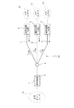
図1は本発明が想定するマルチレートPONシステムの概略構成図である。
図1において、局側装置(OLT)1は、複数の端末装置(ONU)2,3,4に対する集約局として電話局等に設置されており、各端末装置2,3,4は、それぞれPONシステムの加入者宅に設置されている。局側装置1には1本の光ファイバ(幹線)5が接続されている。この光ファイバ5は光カプラ6を介して複数の光ファイバ(支線)7,8,9に分岐した構成になっており、これによって光ファイバ網10が構成されている。分岐した各光ファイバ7,8,9の終端にはそれぞれ前記端末装置2,3,4が接続されている。また、局側装置1は上位ネットワーク11と接続され、各端末装置2,3,4はそれぞれのユーザネットワーク12,13,14と接続されている。
Hereinafter, embodiments of the present invention will be described with reference to the drawings.
[Overall configuration of PON system]
FIG. 1 is a schematic configuration diagram of a multi-rate PON system assumed by the present invention.
In FIG. 1, a station side device (OLT) 1 is installed in a telephone office or the like as a central station for a plurality of terminal devices (ONUs) 2, 3, and 4, and each
図1では、簡単のために3個の端末装置2,3,4が接続された形態を例示しているが、実際には、一つの光カプラ6から32分岐して32個の端末装置を接続することが可能である。また、図1では光カプラ6が一つだけのトポロジーを例示しているが、分岐数の少ない光カプラ6を縦列に複数段配置することにより、広い地域に分散している端末装置を短い光ファイバで局側装置1と接続することもできる。
このPONシステムでは、下りの光波長と上りの光波長を分けて波長分割多重(WDM:Wavelength Division Multiplexing)している。すなわち、局側装置1と端末装置2,3,4間の上り方向通信には単一の波長λ1のレーザ光が使用され、下り方向通信にはその波長λ1とは異なる単一の波長λ2のレーザ光が使用されている。
In FIG. 1, for the sake of simplicity, an example in which three
In this PON system, downstream optical wavelength and upstream optical wavelength are divided and wavelength division multiplexing (WDM) is performed. That is, a laser beam having a single wavelength λ1 is used for uplink communication between the
従って、PONメディア(光ファイバ5,7,8,9)と局側装置1及び各端末装置2,3,4の送受信器の間にはWDMフィルタが備えられており、受信すべき波長成分のみ受信器に送られ、かつ、送信器が出力する光信号はWDMフィルタを介して受信光と多重されて光ファイバ5,7,8,9に送られる。なお、上記各波長λ1,λ2は、IEEE Std 802.3ahTM-2004のClause60に従う場合には、1260nm≦λ1≦1360、及び、1480nm≦λ2≦1500の範囲で選択することができる。
このPONシステムは下り方向にマルチレートでバースト送信が行われるマルチレートPONシステムであって、各端末装置2,3,4の上り方向の伝送レートが互いに異なっている。図1の例では、各端末装置2,3,4の情報通信レートはそれぞれ1G、2G及び10Gbpsであり、1GbpsのGE−PONをベースとして、2Gbpsの信号及び10Gbpsの信号が時分割多重化され、局側装置1に送信されるようになっている。
Accordingly, a WDM filter is provided between the transmitter / receiver of the PON medium (
This PON system is a multi-rate PON system in which burst transmission is performed at a multi-rate in the downstream direction, and the transmission rates in the upstream direction of the
〔局側装置の構成〕
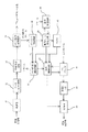
図2は、本発明に係る局側装置1のPONインタフェース部の一例を示している。
図2に示すように、下り方向に送信すべきフレームは一旦下りバッファ16に保存された後、送信制御回路17の指示に基づき符号化回路18に送られる。符号化回路18は送信フレームを所定の方法及び所定のレートに基づいて符号化するとともに、シリアルなビット信号として送信器19に送る。送信器19はシリアルなビット信号を光信号に変換し、WDMフィルタ(図示しない)によって上り光信号と双方向多重した後、PONシステムの光ファイバ5に送出する。
[Configuration of station side equipment]
FIG. 2 shows an example of the PON interface unit of the
As shown in FIG. 2, a frame to be transmitted in the downlink direction is once stored in the
PONシステムの光ファイバ5から受信した光信号はWDMフィルタ(図示しない)によって上り光信号のみが受信機20に入力され、受信器20によって電気信号に変換された後、データリカバリ回路21に入力される。データリカバリ回路21は送信元の端末装置2,3,4が変調したレートでビットデータを復元し、ビットデータを符号同期回路22に送る。符号同期回路22は復元されたビットデータから、送信元の端末装置2,3,4が実施した符号化方法に基づき符号の境界を検出するとともに、復号処理を行いフレームを復元する。復元されたフレームはフレーム種別分別回路23に入力され、PON制御フレームとそれ以外のフレームが分別される。PON制御フレームはタイムスタンプ抽出回路24を経て、制御フレーム処理回路25に送られる。
As for the optical signal received from the
タイムスタンプ抽出回路24はタイムスタンプTSを読取り、それをPON時刻管理回路25に送る。制御フレーム処理回路26はPON制御フレームの種別を判断し、端末装置2,3,4の登録処理に関するものを登録処理回路27に送り、端末装置2,3,4への帯域割当に関するものを帯域割当回路28に送る。登録処理回路27は登録処理の起動を帯域割当回路28に指示するとともに、登録要求のあった端末装置2,3,4との間で定められたシーケンスに基づいたPON制御フレームをやりとりし、その端末装置2,3,4を登録させるか、或いは、登録を拒否する。
The time
端末装置2,3,4を登録させる場合は、登録処理回路27はその端末装置2,3,4への継続的な帯域割当を帯域割当回路28に指示する。
帯域割当回路28は、登録処理回路からの登録処理起動の指示に基づき、登録要求をポーリングするための送信許可を割当て、ゲートフレーム(帯域割当のためのPON制御フレーム)の発行を制御フレーム処理回路26に指示する。また、帯域割当回路28は、制御フレーム処理回路26からレポートフレーム(帯域割当要求のPON制御フレーム)を受けると、所定のポリシーに基づいた帯域割当処理を実行し、個々の端末装置2,3,4に対する送信許可を割当て、ゲートフレームの発行を制御フレーム処理回路26に指示する。
When registering the
The
制御フレーム処理回路26は、登録処理回路27または帯域割当回路28からゲートフレームの発行指示を受けると、対応したゲートフレームを構成し、前記送信制御回路17に送る。なお、端末装置2,3,4の登録及び帯域割当に関するシーケンスの詳細については後述する。
クロック生成回路29は理想的な周波数fを中心として、所定の周波数範囲で自律的に発振し、基準クロックを生成する。PON時刻管理回路25は基準クロックをカウントしてPONカウンタを生成し、このPONカウンタをPONインタフェース部の各要部に配布する。また、PON時刻管理回路25は、PON制御フレームのタイムスタンプを受け取ると、そのフレームの送信元の端末装置2,3,4との間の往復伝搬時間RTTを計算し、このRTT情報をPONインタフェース部の各要部に配布する。
When receiving a gate frame issuance instruction from the
The clock generation circuit 29 oscillates autonomously within a predetermined frequency range around the ideal frequency f, and generates a reference clock. The PON
このとき、PON時刻管理回路25は、直前のRTTとの変化を調べ、変動が所定の範囲を超えた場合は、アラームを生成する。このアラームを受けた場合、登録処理回路27は当該端末装置2,3,4の登録を拒否するなどの必要な処理を行う。
送信制御回路17は制御フレーム処理回路26からPON制御フレームを受け取ると、一旦下りバッファ16に保存するとともに、一般の下りフレームの送信に優先して、PONに送信させる。送信処理は前述の通りである。このとき、PONカウンタの最新の値を参照して、PON制御フレームにタイムスタンプTSを付すとともに、フレームチェックシーケンスをTSの値を反映した値に設定する。
At this time, the PON
When the
〔端末装置の構成〕
図3は、本発明に係る端末装置2,3,4のPONインタフェース部の一例を示している。
PONの光ファイバ7,8,9から受信した光信号はWDMフィルタ(図示しない)によって下り光信号のみが受信機31に入力され、受信器31によって電気信号に変換された後、データリカバリ回路32に入力される。データリカバリ回路32は当該端末装置2,3,4が想定する所定のレート(本実施形態では、1G、2G又は10G)でビットデータを復元し、ビットデータを符号同期回路33に送る。符号同期回路33は復元されたビットデータから、送信元の局側装置1が実施した符号化方法に基づき符号の境界を検出するとともに、復号処理を行いフレームを復元する。
[Configuration of terminal device]
FIG. 3 shows an example of the PON interface unit of the
The optical signals received from the PON
復元されたフレームはフレーム種別分別回路34に入力され、PON制御フレームとそれ以外のフレームが分別される。PON制御フレームはタイムスタンプ抽出回路35を経て、制御フレーム処理回路36に送られる。
タイムスタンプ抽出回路35はタイムスタンプTSを読取り、PON時刻管理回路37
に送る。制御フレーム処理回路36はPON制御フレームの種別を判断し、登録処理に関するものを登録処理回路38に送る。送信許可に関するもの(ゲートフレーム)であった場合は、ゲートフレームに記載されている送信許可情報を送信制御回路39に通知する。
The restored frame is input to the frame
The time
Send to. The control
送信許可情報は、データ種別(登録要求または通常要求:通常要求の場合は帯域要求強制の有無)、送信開始時刻及び送信持続時間で構成されている。登録処理回路38は局側装置1との間で定められたシーケンスに基づいたPON制御フレームをやりとりし、当端末装置2,3,4を登録させる。制御フレーム処理回路36は、登録処理回路38からPON制御フレームの発行指示を受けると、対応したPON制御フレームを構成し、送信制御回路39に送る。なお、端末装置2,3,4の登録及び送信許可に関するシーケンスの詳細については後述する。
The transmission permission information is composed of a data type (registration request or normal request: presence / absence of bandwidth request for normal request), transmission start time, and transmission duration. The
クロック生成回路40は理想的な周波数fを中心として、所定の周波数範囲で自律的に発振し、基準クロックを生成する。PON時刻管理回路37は基準クロックをカウントしPONカウンタを生成する。PONカウンタの値は送信制御回路39から参照可能になっている。また、PON制御フレームのタイムスタンプTSを受け取ると、その値でPONカウンタを更新する。このとき、直前のPONカウンタとの変化を調べ、変動が所定の範囲を超えた場合は、アラームを生成する。このアラームを受け、登録処理回路38は登録を取り下げるなどの必要な処理を行う。
The
上り方向に送信すべきフレームは一旦上りバッファ41に保存されている。上りバッファ41の状態は送信制御回路39が管理している。送信制御回路39は、制御フレーム処理回路36から送信すべきPON制御フレームを受け取ると、一旦上りバッファ41に保存する。また、送信許可で帯域要求強制を指示された場合は、上りバッファ41の状態を反映したレポートフレーム(PON制御フレームの一種)を生成する。
送信制御回路39は制御フレーム処理回路36から送信許可の通知を受けると、送信許可のデータ種別が通常要求である場合には、送信制御回路39はPONカウンタが送信開始時刻に到達した時点で送信器43に発光を指示し、送信持続時間が経過するまでは発光指示を持続する。
A frame to be transmitted in the upstream direction is temporarily stored in the
When the
このとき、発光指示に先立って、上りバッファ41に送信持続時間に見合った量の送信フレームの取り出しを指示する。ただし、帯域要求強制を指示された場合は、レポートフレームを送信しなければないないので、その分上りバッファ41から取り出すデータ量を差し引くとともに、レポートフレームを送信フレーム列に挿入する。このとき極端な例として、レポートフレームのみが送信される場合もある。
他方、当該端末装置2,3,4が未登録の状態であって、制御フレーム処理回路36から登録要求のPON制御フレームを受け取った場合は、送信許可のデータ種別が登録要求であるから、送信制御回路39はPONカウンタが送信開始時刻に到達した時点から、送信持続時間の範囲でランダムな時間ウェイトした後に、送信器に発光を指示し、登録要求のPON制御フレームを送出する時間だけ発光指示を持続する。このとき、発光指示に先立って、上りバッファ41に当該フレームの取り出しを指示する。
At this time, prior to the light emission instruction, the
On the other hand, when the
レポートフレームおよび上りバッファ41から取り出されたフレームは、符号化回路42によって所定の方法および所定のレートに基づいて符号化され、シリアルなビット信号として送信器に送られる。
このとき、送信しようとしているフレームがPON制御フレームであれば、PONカウンタの最新の値を参照して、そのフレームにタイムスタンプTSを付す。送信器43は発光指示がある期間、シリアルなビット信号を光信号に変換し、PONに送出する。一方、送信器43は発光指示がない期間は発光しない。
The report frame and the frame extracted from the
At this time, if the frame to be transmitted is a PON control frame, the latest value of the PON counter is referred to and a time stamp TS is attached to the frame. The
〔往復伝搬時間(RTT)の計算方法〕
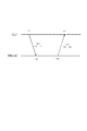
図4は、局側装置1による端末装置2,3,4との間の往復伝搬時間(RTT)を測定する方法を示すシーケンス図である。なお、図4においては、局側装置1をOLT、RTTを測定する特定の端末装置をONU(A)と表示してある。
図4において、OLTは、自身のPONカウンタがT4のとき、ONU(A)から上りのPON制御フレームUS1を受信したとする。このUS1には、ONU(A)がその制御フレームUS1を送出したときの、当該ONU(A)のPONカウンタの値T3が、タイムスタンプTSとして記されている。
[Calculation method of round-trip propagation time (RTT)]
FIG. 4 is a sequence diagram illustrating a method of measuring the round trip propagation time (RTT) between the
In FIG. 4, it is assumed that the OLT receives an upstream PON control frame US1 from the ONU (A) when its PON counter is T4. In this US1, the value T3 of the PON counter of the ONU (A) when the ONU (A) sends out the control frame US1 is described as a time stamp TS.
一方、ONU(A)がUS1を送出する前にOLTから受信した下りのPON制御フレームのうち、直近のものをDS1とすると、このDS1には、OLTがそのPON制御フレームを送出したときの、当該OLTのPONカウンタの値T1が、タイムスタンプTSとして記されている。ONU(A)はDS1を受信した時点において、自身のPONカウンタの値をDS1のTS値(=T1)で更新する。
ここで、当該ONU(A)の往復伝搬時間は、一般に次の式で算出される。
RTT(A)=(T4−T1)−(T3−T2)
また、ONU(A)のT2は、DS1に記されたTS(=T1)によってT1に更新される(∴T2=T1)から、結局、RTT(A)=T4−T3となる。なお、T3は、制御フレームUS1のタイムスタンプTSと同じであるから、RTT(A)=T4−TSと表現することもできる。
On the other hand, if the most recent downlink PON control frame received from the OLT before the ONU (A) sends US1 is DS1, this DS1 contains the data when the OLT sends the PON control frame. A value T1 of the PON counter of the OLT is written as a time stamp TS. When ONU (A) receives DS1, it updates the value of its PON counter with the TS value (= T1) of DS1.
Here, the round-trip propagation time of the ONU (A) is generally calculated by the following equation.
RTT (A) = (T4-T1)-(T3-T2)
Further, T2 of ONU (A) is updated to T1 by TS (= T1) written in DS1 (∴T2 = T1), and eventually RTT (A) = T4-T3. Since T3 is the same as the time stamp TS of the control frame US1, it can also be expressed as RTT (A) = T4-TS.
このように、一般に、OLTは、下りの制御フレームの受信時刻Tr(図4ではT4)と、その制御フレームに記されているTSから、RTT=Tr−TSとして、制御フレームを送出したONU(A)との間のRTTを求めることができ、OLTとONU(A)の基準クロックの同期が維持されている場合には、上記した往復伝搬時間の算出式は常に正確に成立している。
OLTはONU(A)に対して上り帯域を割当てる場合、事前に送信許可情報を記載したゲートフレームをONU(A)に与える。送信許可情報は送信開始時刻と送信持続時間で構成される。送信開始時刻はONU(A)からの上り信号を到着させる時刻からRTTを差し引いたものである。ここで、上り信号を到着させる時刻は、各ONUからの上り信号を稠密に配置させる場合、ONU(A)の直前に上り送信することになっているONUからの上り信号が終了する時刻に、精度に起因するぶれを吸収するため、所定のガードタイムを加えたものになっている。
ところが、OLTとONU(A)の基準クロックの同期が維持されていない場合には、上りのPON制御フレームUS1のタイムスタンプTSとしてのT3は、OLTの時刻に照らした場合の真のT3とは微妙に異なっている恐れがあり、この場合には、前記した(Tr−TS)は真のRTTを表さないことになる。また、OLTとONU(A)の基準クロックの周波数差が一定(≠0)だとすると、(Tr−TS)とRTTの時間的ずれは、図4におけるT2とT3の時間間隔が大きくなるほど拡大する。
As described above, generally, the OLT transmits the control frame as ONT (RTT = Tr−TS) from the reception time Tr of the downlink control frame (T4 in FIG. 4) and the TS described in the control frame. When the RTT between the ALT and the reference clock of the OLT and the ONU (A) is maintained, the above-described formula for calculating the round-trip propagation time is always established accurately.
When the OLT allocates an upstream band to the ONU (A), the OLT gives the ONU (A) a gate frame in which transmission permission information is described in advance. The transmission permission information includes a transmission start time and a transmission duration. The transmission start time is obtained by subtracting RTT from the time at which the upstream signal from ONU (A) arrives. Here, when the upstream signal from each ONU is densely arranged, the time at which the upstream signal arrives is the time when the upstream signal from the ONU that is supposed to perform upstream transmission immediately before the ONU (A) ends. A predetermined guard time is added in order to absorb the shake due to accuracy.
However, when the synchronization of the reference clock of the OLT and the ONU (A) is not maintained, the T3 as the time stamp TS of the upstream PON control frame US1 is the true T3 when compared with the time of the OLT In this case, (Tr-TS) does not represent a true RTT. If the frequency difference between the reference clocks of OLT and ONU (A) is constant (≠ 0), the time difference between (Tr−TS) and RTT increases as the time interval between T2 and T3 in FIG. 4 increases.
そこで、本実施形態では、OLTが、当該OLTとONU(A)とのクロックの周波数差によって発生するタイムスタンプTSのぶれを評価し、このぶれを吸収できる余裕を見込んでその後のゲートフレームを配布する伝送制御方法を採用することにより、OLTとONU(A)との間のクロック同期を前提としなくても、上り信号を衝突させずに配置できるようにしている。
また、本実施形態では、OLTが、送信開始時刻T3が特定のゲートフレームDS1の到着時刻T2の直近に設定されたレポートフレームUS1に含まれるタイムスタンプTSによりRTTを測定することにより、OLTとONU(A)との間のクロック同期を前提としなくても、RTTを正確に求められるようにしている。
Therefore, in this embodiment, the OLT evaluates the fluctuation of the time stamp TS generated by the clock frequency difference between the OLT and the ONU (A), and distributes the subsequent gate frame in anticipation of a margin that can absorb this fluctuation. By adopting this transmission control method, the upstream signals can be arranged without colliding even without assuming clock synchronization between the OLT and the ONU (A).
Further, in the present embodiment, the OLT measures the RTT by the time stamp TS included in the report frame US1 in which the transmission start time T3 is set to the closest time of the arrival time T2 of the specific gate frame DS1, whereby the OLT and the ONU Even if the clock synchronization with (A) is not assumed, the RTT can be obtained accurately.
〔クロック差を考慮した伝送制御方法〕
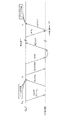
図5は、上記伝送制御方法とレンジング処理の一例を示すシーケンス図である。
図5の例では、上記伝送制御方法をONUの登録に採用している。また、図5においては、局側装置1をOLT、レンジング処理等を行う特定の端末装置をONU(B)と表示してある。
図5に示すように、まず、OLTは登録要求をポーリングするための送信許可フレームDGATE(PON制御フレームの一種である登録用のゲートフレーム)をONU(B)にブロードキャストする。OLTは後の処理のためにDGATEのタイムスタンプTSの値Tdg(DGATEの発信時刻)を記憶しておく。
[Transmission control method considering clock difference]
FIG. 5 is a sequence diagram illustrating an example of the transmission control method and the ranging process.
In the example of FIG. 5, the above transmission control method is employed for ONU registration. In FIG. 5, the station-
As shown in FIG. 5, first, the OLT broadcasts to the ONU (B) a transmission permission frame DGATE (a registration gate frame which is a kind of PON control frame) for polling a registration request. The OLT stores the value Tdg (DGATE transmission time) of the DGATE time stamp TS for later processing.
新たに登録したいONU(B)はDGATEを受信すると、このDGATEに記されているTSで自身のPONカウンタを更新する。そして、DGATEに指示された送信許可時間内に、登録要求フレームREGREQ(PON制御フレームの一種)をOLTに対して送出する。
そこで、OLTはONU(B)の登録要求を受理する場合は、登録フレームREGISTER(PON制御フレームの一種)をONU(B)に送信する。更に、OLTはONU(B)から登録確認フレームREGACK(PON制御フレームの一種)を送出させるために、通常の送信許可フレームGATE(PON制御フレームの一種である通常のゲートフレーム)をONU(B)に送信する。
When the ONU (B) to be newly registered receives DGATE, it updates its PON counter with the TS written in this DGATE. Then, a registration request frame REGREQ (a kind of PON control frame) is sent to the OLT within the transmission permission time designated by DGATE.
Therefore, when the OLT accepts an ONU (B) registration request, the OLT transmits a registration frame REGISTER (a kind of PON control frame) to the ONU (B). Further, the OLT sends a normal transmission permission frame GATE (a normal gate frame which is a kind of PON control frame) to the ONU (B) in order to send a registration confirmation frame REGACK (a kind of PON control frame) from the ONU (B). Send to.
REGISTERの応答として、ONU(B)はGATEに記された送信許可期間にREGACKを送出する。OLTはREGACKを受信し、これによってONU(B)の登録手続きが終了する。
本実施形態では、図3に示すONUにおいて、下り信号からデータのみを抽出しクロックを抽出ない構成になっていることからも明らかな通り、OLTからの連続的な信号に含まれるクロックをもとにしたクロック同期を行わない。従って、OLTとONUの基準クロックの周波数は厳密には一致しないが、理想的な周波数fを基準として、周波数差はある範囲以内になるよう構成されている。なお、このクロックの周波数差を(比で表して)dfとすると、その上限dfmaxは、通常、±100ppm程度に設定することができる。
As a response to REGISTER, ONU (B) sends REGACK during the transmission permission period described in GATE. The OLT receives REGACK, thereby completing the ONU (B) registration procedure.
In the present embodiment, the ONU shown in FIG. 3 has a configuration in which only data is extracted from the downstream signal and no clock is extracted, as is apparent from the clock included in the continuous signal from the OLT. Do not synchronize the clock. Accordingly, the frequency of the OLT and ONU reference clocks do not exactly match, but the frequency difference is configured to be within a certain range with the ideal frequency f as a reference. If the frequency difference of the clock is df (expressed as a ratio), the upper limit dfmax can usually be set to about ± 100 ppm.
OLTは、ONU(B)からREGREQを受信したとき、式(Tr−TS)、すなわち、(REGREQの受信時刻−REGREQに記されているTS)によって、第一段階のRTT1(B)を求める。
更に、OLTは、式(TS−Tdg)、すなわち、(REGREQに記されているTS−DGATEの発信時刻)と、前記dfmaxとから、REGREQのタイムスタンプTSに内方されている時間的なぶれの上限ΔRmaxを評価する。このΔRmaxは、具体的には、(TS−Tdg)×dfmaxによって算出される。
When the OLT receives the REGREQ from the ONU (B), the OLT obtains the first-stage RTT1 (B) by the equation (Tr-TS), that is, (REGREQ reception time-TS described in the REGREQ).
Further, the OLT is a time-dependent fluctuation in the time stamp TS of the REGREQ from the formula (TS-Tdg), that is, (the transmission time of TS-DGATE described in the REGREQ) and the dfmax. The upper limit ΔRmax of is evaluated. Specifically, ΔRmax is calculated by (TS−Tdg) × dfmax.
OLTは、ONU(B)にREGACK用のGATE(送信持続時間をTL(B)とする)を与えるに際して、他のONUへ与えた送信許可との関連において、他のONUの送信と衝突なく、かつ、無駄なく上り帯域が使われるように、OLTへの到着時刻TT(B)を決定するとともに、RTT1(B)を勘案して(具体的にはRTT1(B)を差し引いて)送信開始時刻を決める。ONU(B)の上り信号がすべて到着し終える時刻TE(B)はTE(B)=TT(B)+TL(B)なので、ONU(B)の直後に送信させるONU(ONU(N)と表記)の上り信号をOLTに到着させる時刻TT(N)はTE(B)に所定のバーストギャップを加えたものとする。
また、OLTは、前記送信開始時刻とGATEを送信するであろう時刻との差と前記dfmaxとからONU(B)が解釈する送信開始時刻の変動(ΔSmax)を算出し、dfmaxがONU(B)の送信持続時間にもたらす変動(ΔLmax)も算出する。
When the OLT gives a GATE for REGACK to the ONU (B) (transmission duration is TL (B)), there is no collision with the transmission of other ONUs in relation to the transmission permission given to the other ONUs. In addition, the arrival time TT (B) to the OLT is determined so that the upstream band can be used without waste, and the transmission start time is determined in consideration of RTT1 (B) (specifically, RTT1 (B) is subtracted). Decide. Since the time TE (B) at which all the upstream signals of the ONU (B) have arrived is TE (B) = TT (B) + TL (B), it is expressed as ONU (ONU (N) to be transmitted immediately after the ONU (B). The time TT (N) at which the upstream signal) arrives at the OLT is assumed to be obtained by adding a predetermined burst gap to TE (B).
Further, the OLT calculates a variation (ΔSmax) of the transmission start time interpreted by the ONU (B) from the difference between the transmission start time and the time when the GATE will be transmitted and the dfmax, and the dfmax is calculated as ONU (B The fluctuation (ΔLmax) caused in the transmission duration of) is also calculated.
そして、OLTは、これらのぶれと前記ΔRmaxとを勘案して、直前のONUの送信と衝突しないよう、更に調整した送信開始時刻をGATEに記載する。
より具体的に言えば、OLTの基準クロックに対してONU(B)の基準クロックが速い場合、RTT1(B)は実際より小さくなっている反面、ONU(B)が上り信号を送信開始する時刻はOLTの時刻を基準にすると早まっている。すなわち、ONU(B)からの上り信号はTT(B)よりΔSmax−ΔRmaxだけ早く到着する。
逆に、OLTの基準クロックに対してONU(B)の基準クロックが速い場合、ONU(B)からの上り信号はΔRmax−ΔSmaxだけ早く到着する。OLTはONU(B)の基準クロックが速いか遅いかわからないため、いずれであってもONU(B)からの上り信号が、直前のONUの送信と衝突しないよう、OLTはTT(B)をTT(B)+|ΔRmax−ΔSmax|に補正する。
ONU(B)の基準クロックが遅かった場合、上り信号がすべて到着し終える時刻はOLT時刻を基準にすると遅くなるため、ONU(N)の上り信号と衝突する恐れがある。これを防ぐために、TT(N)をTT(N)+ΔSmax+ΔLmaxに補正する。ここで、もとのTT(N)は前記補正したTT(B)をもとに求められたものとする。OLTはONU(N)に対してGATEを与えるに際しては、ONU(B)と同様の調整をさらに加える(以後同様)。これらの調整は、効率の点で限界を追究したものであるので、多少の効率を犠牲にした変形は本発明の範囲内である。
Then, the OLT takes into account these fluctuations and the above ΔRmax, and describes the further adjusted transmission start time in the GATE so as not to collide with the transmission of the previous ONU.
More specifically, when the ONU (B) reference clock is faster than the OLT reference clock, the RTT1 (B) is smaller than the actual time, but the ONU (B) starts transmitting an upstream signal. Is earlier than the OLT time. That is, the upstream signal from ONU (B) arrives earlier than TT (B) by ΔSmax−ΔRmax.
Conversely, when the ONU (B) reference clock is faster than the OLT reference clock, the upstream signal from the ONU (B) arrives earlier by ΔRmax−ΔSmax. Since the OLT does not know whether the reference clock of the ONU (B) is fast or slow, the OLT changes the TT (B) to TT so that the upstream signal from the ONU (B) does not collide with the transmission of the previous ONU. (B) Correction to + | ΔRmax−ΔSmax |
When the reference clock of ONU (B) is late, the time when all the upstream signals have arrived is delayed based on the OLT time, so there is a possibility of colliding with the upstream signal of ONU (N). In order to prevent this, TT (N) is corrected to TT (N) + ΔSmax + ΔLmax. Here, it is assumed that the original TT (N) is obtained based on the corrected TT (B). When the OLT gives GATE to the ONU (N), the OLT further performs the same adjustment as the ONU (B) (the same applies hereinafter). Since these adjustments are pursuing limits in terms of efficiency, variations at the expense of some efficiency are within the scope of the present invention.
このように、本実施形態のPONシステムでは、OLTとONU(B)のクロックの周波数差によって発生する、登録要求フレーム(図5ではREGREQ)に含まれるタイムスタンプTSの変動や、ONU(B)の送信開始時刻と送信継続時間の変動を算出し、この変動を吸収できる余裕を見込んでその後のゲートフレーム(図5ではGATE)を配布するようにしたので、OLTとONU(B)との間でクロック同期をさせなくても、他のONUからの上り信号を衝突させずに配置することができる。 As described above, in the PON system of this embodiment, the variation in the time stamp TS included in the registration request frame (REGREQ in FIG. 5) generated by the frequency difference between the clocks of the OLT and the ONU (B), and the ONU (B) Since the fluctuation of the transmission start time and the transmission continuation time is calculated and the subsequent gate frame (GATE in FIG. 5) is distributed in consideration of a margin that can absorb this fluctuation, between the OLT and the ONU (B) Thus, the upstream signals from other ONUs can be arranged without colliding without clock synchronization.
〔クロック差を考慮したレンジング処理〕
図5に示すように、本実施形態のOLTは、上記の登録処理を行った後、以下の方法で更に第二段階のレンジング処理を行う。
OLTは、レポートフレーム(PON制御フレームの一種であって、帯域要求を記載)を強制するGATEを送出する。このGATEとREPORTは当該第二回目のレンジング処理の精度を高めるのが目的であり、GATEをONU(B)が受信するであろう時刻に、できる限り送信開始時刻を近づけている。
[Ranging considering the clock difference]
As shown in FIG. 5, the OLT according to the present embodiment performs the second registration process by the following method after performing the registration process.
The OLT sends out a GATE forcing a report frame (a kind of PON control frame, which describes a bandwidth request). The purpose of the GATE and REPORT is to increase the accuracy of the second ranging process, and the transmission start time is as close as possible to the time when the ONU (B) will receive the GATE.
すなわち、ONU(B)からのREPORTの送信開始時刻が、ONU(B)へのGATEの到着時刻(ONU(B)のPONカウンタはGATEのタイムスタンプTSで更新されるため、結局はGATEのTSに等しい。)に対してごく僅かな時間差ΔTしか離れていない直近に設定されている。具体的には、IEEE802.3ahTMにおいて、上記時間差ΔTは16μs以上となっており、ここでは16μs程度の短時間(ΔTmin)に設定する。この短時間は、IEEE802.3ahTMで認められている時間差の上限(1ms)の1/100程度である。
そして、OLTは、RTTの再計算用のGATEに対応する上記REPORTを受信したときに、式(Tr−TS)、すなわち、(REPORTの受信時刻−REPORTのタイムスタンプTS)から、正確なRTT2(B)を求める。
That is, the REPORT transmission start time from the ONU (B) is the arrival time of the GATE to the ONU (B) (the PON counter of the ONU (B) is updated with the GATE time stamp TS. It is set to the nearest distance that is only a slight time difference ΔT. Specifically, in IEEE 802.3ah TM , the time difference ΔT is 16 μs or more, and is set to a short time (ΔTmin) of about 16 μs here. This short time is about 1/100 of the upper limit (1 ms) of the time difference recognized in IEEE802.3ah ™ .
Then, when the OLT receives the REPORT corresponding to the GATE for recalculating the RTT, the OLT obtains an accurate RTT2 (from REPORT reception time-REPORT time stamp TS) from the formula (Tr-TS). B).
このように、本実施形態のPONシステムでは、送信開始時刻がGATEの到着時刻の直近に設定されたREPORTに含まれるタイムスタンプTSによってRTT2(B)を測定するようにしたので、ONU(B)での送信待ち時間が殆ど無い状態でREPORTがOLTに返信される。このため、OLTとONU(B)とのクロックの周波数差があっても、その差がONU(B)のタイムスタンプTSに殆ど影響せず、RTT2(B)を正確に求めることができる。従って、OLTとONU(B)間のクロック同期を前提としなくても、往復伝搬時間を正確に求めることができるし、往復伝搬時間が正確であるから、各ONUからの上り信号をできるだけ稠密に配置することも可能となる。 As described above, in the PON system according to the present embodiment, RTT2 (B) is measured by the time stamp TS included in the REPORT whose transmission start time is set closest to the arrival time of the GATE. Therefore, the ONU (B) REPORT is returned to the OLT with almost no transmission waiting time. For this reason, even if there is a clock frequency difference between OLT and ONU (B), the difference hardly affects the time stamp TS of ONU (B), and RTT2 (B) can be obtained accurately. Therefore, the round-trip propagation time can be accurately obtained without assuming clock synchronization between the OLT and the ONU (B), and since the round-trip propagation time is accurate, the upstream signal from each ONU is as dense as possible. It can also be arranged.
ところで、本実施形態のOLTとしては、PON制御フレームを受信する度に式(Tr−TS)でRTTを算出して更新するのではなく、ある更新条件に従って選択的に更新するものを採用することができる。
例えば、本来の帯域割当を目的としたGATE−REPORTにおいて、ONUでの経過時間(GATEを受信してからONUによる送信開始までの時間)が所定の範囲内(例えば、20μs以内)にある場合(以下、RTT更新条件という。)に、OLTがそのREPORTを受信したときにRTTを更新することにしてもよい。
By the way, as the OLT of the present embodiment, an OLT that is selectively updated in accordance with a certain update condition is employed instead of calculating and updating the RTT with the formula (Tr-TS) every time a PON control frame is received. Can do.
For example, in GATE-REPORT for the purpose of original bandwidth allocation, the elapsed time in the ONU (the time from the reception of GATE until the start of transmission by the ONU) is within a predetermined range (for example, within 20 μs) ( Hereinafter, the RTT may be updated when the OLT receives the REPORT.
この場合においては、ある特定のONUのRTTを更新してから、予め決められた期限内(例えば、1s以内等)にそのONUとの間のGATE−REPORTが上記RTT更新条件を満たさなかったか、或いは、そのONUからPON制御フレームを受信したときの(Tr−TS)とその時点のRTTとの差が一定値を超えた場合に、OLTが再度前記した第二段階のレンジング処理を実行するようにすればよい。
このため、REPORTを受ける度にRTTの計算と更新を行う従来の場合(前記標準規格の場合)に比べて、レンジング処理の回数が減少し、OLTでの演算負荷を低減することができる。
In this case, whether the GATE-REPORT with the ONU did not satisfy the RTT update condition within a predetermined time limit (for example, within 1 s) after updating the RTT of a specific ONU, Alternatively, when the difference between (Tr−TS) when the PON control frame is received from the ONU and the RTT at that time exceeds a certain value, the OLT executes the second-stage ranging process again. You can do it.
For this reason, the number of times of the ranging process is reduced and the calculation load on the OLT can be reduced as compared with the conventional case where the RTT is calculated and updated every time REPORT is received (in the case of the standard).
更に、本実施形態において、OLTはREPORTに基づいて帯域割当量を計算した時点で直ちにGATEを送信するのではなく、ONUでの経過時間ができる限り短くなるよう、意図的に遅延させるようにしてもよい。具体的には、レポートを到着させたい時刻に対して、RTT2(B)とΔRminとを差し引いた時刻を限度として、この限度近くまで遅延させる。この場合には、GATEの送信時刻を意図的に遅らせることで、ONU(B)での送信待ち時間を可及的に短くでき、OLTとONU(B)との間のクロックの周波数差に基づくONU(B)のタイムスタンプTSのぶれが小さくなり、前記RTT更新条件が満たされ易くなる。
従って、この場合には、REPORTがほぼ確実に前記RTT更新条件を満たすことになるので、REPORTを受信する度に式(Tr−TS)でRTTを更新してもよい。
また、主信号用のGATE送信も意図的に遅延させることにより、送信開始時刻の変動が小さくなり、上り信号をより稠密に配置することができる。
Furthermore, in this embodiment, the OLT does not immediately transmit GATE when the bandwidth allocation amount is calculated based on REPORT, but intentionally delays the elapsed time in the ONU as short as possible. Also good. Specifically, with respect to the time at which the report is desired to arrive, the time obtained by subtracting RTT2 (B) and ΔRmin is the limit, and the time is delayed to near this limit. In this case, the transmission waiting time in the ONU (B) can be shortened as much as possible by intentionally delaying the transmission time of the GATE, based on the frequency difference of the clock between the OLT and the ONU (B). The fluctuation of the time stamp TS of the ONU (B) is reduced, and the RTT update condition is easily satisfied.
Accordingly, in this case, since REPORT almost certainly satisfies the RTT update condition, the RTT may be updated by the equation (Tr-TS) each time REPORT is received.
Moreover, by intentionally delaying the GATE transmission for the main signal, the fluctuation of the transmission start time is reduced, and the upstream signals can be arranged more densely.
〔RTTとクロック差の測定〕
図6は、本発明の別実施形態のレンジング処理を示すシーケンス図である。
図6に示すように、この別実施形態では、OLTは、正確なRTTの算出を行う第二段階のレンジング処理において、二つのREPORTの送信を強制する一つのGATEを送出する。このGATEには一つのタイムスタンプTSと二つの送信許可が含まれている。
このとき、一つ目の第1のREPORT用の送信許可は、前記レンジング処理におけるREPORT用の送信許可と同様に、GATEの受信時刻と直近の送信時刻とされている。他方、二つ目の第2のREPORT用の送信許可は、ONU(B)での経過時間を出来るだけ長くとるのが望ましい。
[Measurement of RTT and clock difference]
FIG. 6 is a sequence diagram illustrating a ranging process according to another embodiment of the present invention.
As shown in FIG. 6, in this alternative embodiment, the OLT sends out one GATE forcing the transmission of two REPORTs in the second stage ranging process in which an accurate RTT is calculated. This GATE includes one time stamp TS and two transmission permissions.
At this time, the transmission permission for the first first REPORT is the GATE reception time and the latest transmission time, similar to the REPORT transmission permission in the ranging process. On the other hand, it is desirable that the transmission permission for the second second REPORT should be as long as possible in the ONU (B).
従って、第1のREPORTを受信した時の式(Tr−TS)は、OLTとONU(B)の正確なRTTを反映しており、また、これら二つのREPORTが伝送される間でのRTTの変化は比較的小さいので、第1のREPORT受信時の(Tr−TS)と第2のREPORT受信時のそれとの差は、OLTとONUとの間のクロック周波数の差に起因すると言える。
従って、この別実施形態では、OLTは上記の測定から、RTTとともにクロック周波数の差dfを算出するようにしている。従って、この場合には、予め設定された固定値である前記dfmaxによる時間的ぶれではなく、実際に測定された上記dfによるずれを勘案して、GATEによって送信開始時刻を調整することができる。
この場合、OLTはONU(B)の基準クロックが速いか遅いかわかっているため、ΔSmax、ΔLmaxは正負の値(遅くなる方が正)をとると考え、TT(B)の補正については、TT(B)−ΔSmaxとし、さらに、TT(N)の補正についてはTT(N)+ΔSmax+ΔLmaxとすればよい(以後同様)。これらの調整は、効率の点で限界を追究したものであるので、多少の効率を犠牲にした変形は本発明の範囲内である。
Therefore, the equation (Tr-TS) when the first REPORT is received reflects the exact RTT of the OLT and ONU (B), and the RTT between these two REPORTs is transmitted. Since the change is relatively small, it can be said that the difference between (Tr-TS) at the time of receiving the first REPORT and that at the time of receiving the second REPORT is due to the difference in clock frequency between the OLT and the ONU.
Therefore, in this alternative embodiment, the OLT calculates the clock frequency difference df together with the RTT from the above measurement. Therefore, in this case, the transmission start time can be adjusted by GATE in consideration of the actually measured deviation due to the df, not the temporal fluctuation due to the dfmax that is a preset fixed value.
In this case, since OLT knows whether the reference clock of ONU (B) is fast or slow, it is considered that ΔSmax and ΔLmax take positive and negative values (the slower one is positive), and the correction of TT (B) is as follows: TT (B) −ΔSmax is set, and TT (N) is corrected by TT (N) + ΔSmax + ΔLmax (the same applies hereinafter). Since these adjustments are pursuing limits in terms of efficiency, variations at the expense of some efficiency are within the scope of the present invention.
なお、図6の例では、第1のREPORTの送信時間をGATEの受信時間と近接させた場合を例示しているが、dfの測定方法はこれに限定されない。すなわち、精度は劣るものの、ONUでの経過時間が異なる独立した二つのGATE−REPORTから、RTTとdfを算出してもよい。この場合、OLT或いはONUのクロック周波数が環境条件等で経時変化するので、dfの計算もRTTと同様に継続的に実施する。本来のGATE−REPORT処理では測定条件が満足されない場合、前記第二段階のレンジングを起動する。 In the example of FIG. 6, the case where the transmission time of the first REPORT is set close to the reception time of GATE is illustrated, but the method for measuring df is not limited to this. That is, although the accuracy is inferior, RTT and df may be calculated from two independent GATE-REPORTs having different elapsed times in the ONU. In this case, since the clock frequency of the OLT or ONU changes with time due to environmental conditions or the like, the calculation of df is continuously performed in the same manner as the RTT. If the measurement conditions are not satisfied in the original GATE-REPORT process, the second-stage ranging is started.
〔端末装置の変形例〕
図7は、本発明の別実施形態に係る端末装置2,3,4のPONインタフェース部を示している。
この図7に示す端末装置2,3,4のインタフェース部は、図3に示すそれとほぼ同様の構成になっているので、同じ構成要素については図面に同一の符号を付してその説明を省略し、ここでは差異点のみ説明する。
[Modification of terminal device]
FIG. 7 shows the PON interface unit of the
The interface units of the
この別実施形態では、基準クロック生成回路が、外部より周波数が制御可能なVCXO45で構成され、このVCXO45の周波数制御を制御フレーム処理回路36が行う点が、図3の場合と異なる。
初期状態においては、制御フレーム処理回路36はVCXO45の周波数を中央値に設定している。このときのVCXO45の実際の周波数は理想的な周波数fを中心として定められた周波数範囲に位置する。この図7のONUに対応したOLTは、図2のOLTと同様に、ONUの登録処理とレンジング処理を行い、第二段階のレンジング処理の結果として、クロックの周波数差dfを求めることができるものとする。
In this other embodiment, the reference clock generation circuit is configured by a
In the initial state, the control
。
そこで、OLTは、周波数差dfをもとにして、ONUとの基準クロック周波数のずれを一種のPON制御フレームとして、当該ONUに通知する。
これに対して、この別実施形態のONUは、上記PON制御フレームを受信すれば制御フレーム処理回路36が、その周波数のずれdfが小さくなるように前記VCXO45を制御する。なお、周波数ずれの通知は、周波数差dfの情報そのものでもよいし、速くするか遅くするかのそのままにするかの簡略な情報であってもよい。また、この通知にはPON制御フレームではなく、OAMフレームのような別種のフレームを用いてもよい。
.
Therefore, the OLT notifies the ONU of a difference in the reference clock frequency from the ONU as a kind of PON control frame based on the frequency difference df.
On the other hand, in the ONU of this another embodiment, when receiving the PON control frame, the control
このようなレンジング処理とONUでの基準クロックの調整を、周波数差dfが十分小さな所定範囲内に収まるまで行った後に、本来の帯域割当通信を含む主信号通信を行うようにすれば、OLTにおいてクロックの周波数差に基づく時間的ずれを補償する必要が無くなるので、dfによるずれを勘案するOLTでの処理をスキップすることにしてもよい。
或いは、ONUの登録後に集中して、レンジング処理とONUの基準クロックの調整を行うことによって、dfによるずれを勘案する処理をOLTに実装しないようにしてもよい。この場合、継続的なレンジングにより周波数差dfの変化をトレースし、ずれが大きくなった段階で、再調整を行うようにすればよい。
If such a ranging process and the adjustment of the reference clock in the ONU are performed until the frequency difference df falls within a sufficiently small predetermined range, then main signal communication including the original band allocation communication is performed in the OLT. Since it is not necessary to compensate for the time lag based on the clock frequency difference, the OLT process that takes into account the df lag may be skipped.
Alternatively, the processing that takes into account the deviation due to df may not be implemented in the OLT by concentrating after the ONU registration and adjusting the ONU reference clock. In this case, the change of the frequency difference df is traced by continuous ranging, and readjustment may be performed when the deviation becomes large.
なお、本実施形態の図1では、マルチレートPONシステムに本発明を適用した場合を例示したが、本発明は、各端末装置の伝送レートが固定の通常のPONシステムに採用することもできる。 In FIG. 1 of the present embodiment, the case where the present invention is applied to the multi-rate PON system is illustrated, but the present invention can also be adopted in a normal PON system in which the transmission rate of each terminal device is fixed.
1 局側装置
2 端末装置(1G用)
3 端末装置(2G用)
4 端末装置(10G用)
5 光ファイバ
6 光カプラ
7 光ファイバ
8 光ファイバ
9 光ファイバ
10 光ファイバ網
GATE ゲートフレーム
REPORT レポートフレーム
TS タイムスタンプ
RTT 往復伝搬時間
1
3 Terminal device (for 2G)
4 Terminal device (for 10G)
5
Claims (14)
前記局側装置が前記タイムスタンプの変動を吸収できる余裕を前記上り信号を到着させる時刻に見込んで前記各端末装置へゲートフレームを配布することを特徴とするPONシステム。 A station-side device, an optical fiber network configured to branch from an optical fiber connected to the station-side device to a plurality of optical fibers via an optical coupler, and a plurality of devices connected to the ends of the branched optical fibers, respectively And the terminal side device obtains the round-trip propagation time between the terminal device that sent the PON control frame from the difference between the time stamp included in the received PON control frame and its own PON counter. In the PON system that distributes the gate frame to the terminal device at the transmission start time obtained by subtracting the round-trip propagation time from the time at which the uplink signal from the terminal device arrives,
A PON system that distributes a gate frame to each of the terminal devices in consideration of a time when the station side device can absorb the fluctuation of the time stamp at a time when the upstream signal arrives.
前記局側装置が、送信開始時刻が前記特定のゲートフレームの到着時刻の直近に設定された前記レポートフレームに含まれるタイムスタンプにより前記往復伝搬時間を測定することを特徴とするPONシステム。 A station-side device, an optical fiber network configured to branch from an optical fiber connected to the station-side device to a plurality of optical fibers via an optical coupler, and a plurality of devices connected to the ends of the branched optical fibers, respectively Round-trip propagation between the terminal device that sent the report frame from the difference between the time stamp included in the report frame corresponding to the specific gate frame and its own PON counter. In the PON system for obtaining the time and distributing the gate frame to the terminal device at the transmission start time obtained by subtracting the round-trip propagation time from the time at which the uplink signal from the terminal device arrives.
The PON system, wherein the station side device measures the round-trip propagation time based on a time stamp included in the report frame whose transmission start time is set closest to the arrival time of the specific gate frame.
この周波数差によって発生し得る前記各端末装置の送信開始時刻の変動を吸収できる余裕を前記上り信号を到着させる時刻に見込んで前記各端末装置へゲートフレームを配布する請求項4〜6のいずれか1項に記載のPONシステム。 The station side device, based on the difference between the round-trip propagation times measured using the time stamps of two or more report frames with different time intervals returned in response to the specific gate frame, Perform clock difference measurement processing to measure the clock frequency difference with each terminal device,
7. The gate frame is distributed to each of the terminal devices in consideration of a margin that can absorb a change in transmission start time of each of the terminal devices that may occur due to this frequency difference at the time of arrival of the uplink signal. The PON system according to item 1.
前記タイムスタンプの変動を吸収できる余裕を前記上り信号を到着させる時刻に見込んで前記各端末装置へゲートフレームを配布することを特徴とするPONシステムの局側装置。 Reciprocal propagation between a plurality of terminal devices connected in a P2MP form via optical fibers and the terminal device that sent out the PON control frame based on the difference between the time stamp included in the received PON control frame and its own PON counter In the station side device of the PON system that obtains the time and distributes the gate frame to the terminal device at the transmission start time obtained by subtracting the round-trip propagation time from the time at which the uplink signal from the terminal device arrives.
A station-side device of a PON system, wherein a gate frame is distributed to each of the terminal devices in consideration of a time for absorbing the fluctuation of the time stamp at a time when the upstream signal arrives.
送信開始時刻が前記特定のゲートフレームの到着時刻の直近に設定された前記レポートフレームに含まれるタイムスタンプにより前記往復伝搬時間を測定することを特徴とするPONシステムの局側装置。 Between a terminal device that is connected to a plurality of terminal devices via an optical fiber in the P2MP form and that has transmitted the report frame based on a difference between a time stamp included in a report frame corresponding to a specific gate frame and its own PON counter In the station-side device of the PON system that distributes the gate frame to the terminal device at the transmission start time obtained by subtracting the round-trip propagation time from the time at which the uplink signal from the terminal device arrives.
A station-side apparatus of a PON system, wherein the round-trip propagation time is measured by a time stamp included in the report frame whose transmission start time is set closest to the arrival time of the specific gate frame.
前記局側装置とのクロックの周波数差に関する情報を含む制御フレームを前記局側装置から受け取り、この周波数差が小さくなるように自身のクロックを調整することにより、前記局側装置からの下り信号に基づいた網同期を行わず、自立したクロックで上り信号の送信タイミングを生成することを特徴とするPONシステムの端末装置。 When the local time reaches the transmission start time set in the gate frame distributed from the station side device and connected to the station side device via the optical fiber in the P2MP form, the transmission of the uplink signal is started, and the report When transmitting a frame, in the terminal device of the PON system in which the local time when transmitting the report frame is described in the report frame,
By receiving a control frame including information on the frequency difference of the clock with the station side device from the station side device and adjusting its own clock so that this frequency difference becomes small, it becomes a downlink signal from the station side device. A terminal device of a PON system that generates uplink signal transmission timing with an independent clock without performing network synchronization based on the terminal device.
Priority Applications (1)
| Application Number | Priority Date | Filing Date | Title |
|---|---|---|---|
| JP2006118796A JP2007295151A (en) | 2006-04-24 | 2006-04-24 | Pon system and station side apparatus and terminal used for the same |
Applications Claiming Priority (1)
| Application Number | Priority Date | Filing Date | Title |
|---|---|---|---|
| JP2006118796A JP2007295151A (en) | 2006-04-24 | 2006-04-24 | Pon system and station side apparatus and terminal used for the same |
Publications (1)
| Publication Number | Publication Date |
|---|---|
| JP2007295151A true JP2007295151A (en) | 2007-11-08 |
Family
ID=38765339
Family Applications (1)
| Application Number | Title | Priority Date | Filing Date |
|---|---|---|---|
| JP2006118796A Pending JP2007295151A (en) | 2006-04-24 | 2006-04-24 | Pon system and station side apparatus and terminal used for the same |
Country Status (1)
| Country | Link |
|---|---|
| JP (1) | JP2007295151A (en) |
Cited By (8)
| Publication number | Priority date | Publication date | Assignee | Title |
|---|---|---|---|---|
| JP2009150872A (en) * | 2007-12-19 | 2009-07-09 | Mitsubishi Electric Research Laboratories Inc | Method and system for presuming relative clock frequency difference in order to raise bi-directional radio distance measuring accuracy |
| WO2010082879A1 (en) * | 2009-01-16 | 2010-07-22 | Telefonaktiebolaget L M Ericsson (Publ) | A method and an interconnecting node for use in an access network |
| WO2010105475A1 (en) * | 2009-03-20 | 2010-09-23 | 中兴通讯股份有限公司 | Method and system for transmitting time in passive optical network |
| JP2011160195A (en) * | 2010-02-01 | 2011-08-18 | Nippon Telegr & Teleph Corp <Ntt> | Band allocating device, and band allocating method |
| JP2011160194A (en) * | 2010-02-01 | 2011-08-18 | Nippon Telegr & Teleph Corp <Ntt> | Band allocating device, and band allocating method |
| WO2012090274A1 (en) * | 2010-12-27 | 2012-07-05 | 三菱電機株式会社 | Relay device, station side optical communication device, communication system, and bandwidth allocation method |
| JP2012147076A (en) * | 2011-01-07 | 2012-08-02 | Nec Corp | Communication system, optical line terminal apparatus and information processing method |
| JP2016046744A (en) * | 2014-08-26 | 2016-04-04 | 日本電信電話株式会社 | Optical line terminal in optical transmission system |
-
2006
- 2006-04-24 JP JP2006118796A patent/JP2007295151A/en active Pending
Cited By (13)
| Publication number | Priority date | Publication date | Assignee | Title |
|---|---|---|---|---|
| JP2009150872A (en) * | 2007-12-19 | 2009-07-09 | Mitsubishi Electric Research Laboratories Inc | Method and system for presuming relative clock frequency difference in order to raise bi-directional radio distance measuring accuracy |
| WO2010082879A1 (en) * | 2009-01-16 | 2010-07-22 | Telefonaktiebolaget L M Ericsson (Publ) | A method and an interconnecting node for use in an access network |
| US9425983B2 (en) | 2009-01-16 | 2016-08-23 | Telefonaktiebolaget Lm Ericsson (Publ) | Method and an interconnecting node for use in an access network |
| US20120020668A1 (en) * | 2009-01-16 | 2012-01-26 | Telefonaktiebolaget Lm Ericsson (Publ) | Method And An Interconnecting Node For Use In An Access Network |
| US8725002B2 (en) | 2009-03-20 | 2014-05-13 | Zte Corporation | Method and system for transmitting time in passive optical network |
| WO2010105475A1 (en) * | 2009-03-20 | 2010-09-23 | 中兴通讯股份有限公司 | Method and system for transmitting time in passive optical network |
| JP2011160195A (en) * | 2010-02-01 | 2011-08-18 | Nippon Telegr & Teleph Corp <Ntt> | Band allocating device, and band allocating method |
| JP2011160194A (en) * | 2010-02-01 | 2011-08-18 | Nippon Telegr & Teleph Corp <Ntt> | Band allocating device, and band allocating method |
| JP5328994B2 (en) * | 2010-12-27 | 2013-10-30 | 三菱電機株式会社 | Relay device, station side optical communication device, communication system, and bandwidth allocation method |
| WO2012090274A1 (en) * | 2010-12-27 | 2012-07-05 | 三菱電機株式会社 | Relay device, station side optical communication device, communication system, and bandwidth allocation method |
| US9112612B2 (en) | 2010-12-27 | 2015-08-18 | Mitsubishi Electric Corporation | Relay device, station-side optical communication device, communication system, and bandwidth allocation method |
| JP2012147076A (en) * | 2011-01-07 | 2012-08-02 | Nec Corp | Communication system, optical line terminal apparatus and information processing method |
| JP2016046744A (en) * | 2014-08-26 | 2016-04-04 | 日本電信電話株式会社 | Optical line terminal in optical transmission system |
Similar Documents
| Publication | Publication Date | Title |
|---|---|---|
| JP5210959B2 (en) | Optical passive network system and operation method thereof | |
| US8818201B2 (en) | Optical communication | |
| US8467684B2 (en) | Apparatus of adjusting optical signal transmission timing | |
| US8208815B1 (en) | Bit accurate upstream burst transmission phase method for reducing burst data arrival variation | |
| JP5111092B2 (en) | Network system and OLT | |
| JP2007295151A (en) | Pon system and station side apparatus and terminal used for the same | |
| CN108370270B (en) | Dynamic bandwidth allocation method and device and passive optical network system | |
| US7660333B2 (en) | Method and apparatus for detecting and compensating for jitter in a communications network | |
| US9871614B2 (en) | WDM/TDM-PON system and transmission start time correction method thereof | |
| CN106576012A (en) | Rogue optical network unit mitigation in passive optical networks | |
| JP2009171441A (en) | Registration method for house-side device, ason system, and station-side device | |
| JP2011217298A (en) | Pon system, station-side device and terminal-side device thereof, and rtt correction method | |
| JP6381392B2 (en) | PON system, OLT, ONU, and transmission method | |
| JP4173044B2 (en) | Method of using upstream bandwidth in optical burst transmission / reception network | |
| JP6403634B2 (en) | Station side apparatus and delay related setting value correction method | |
| JP5023514B2 (en) | Terminal device used in PON system and control method of transmission timing thereof | |
| CN103139669A (en) | Method and system for sending data | |
| JP2009171434A (en) | Ason system and optical switch device used for the same, and station-side device | |
| JP2016143950A (en) | PON system | |
| KR100606027B1 (en) | Method for compensating round trip delay in transmission of ethernet frames over a passive optical network and passive optical network system therefor | |
| KR101217962B1 (en) | Method for clock synchronizing and ethernet system for the same | |
| Kamchevska et al. | Synchronization algorithm for SDN-controlled all-optical TDM switching in a random length ring network | |
| KR101046110B1 (en) | Method and apparatus for determining cycle time of passive optical network | |
| JP4958984B2 (en) | Bandwidth allocation apparatus and bandwidth allocation method | |
| JP2015170991A (en) | Wavelength monitoring method, wavelength monitoring system and master node |