JP2007286609A - Liquid crystal device and projector with the same - Google Patents

Liquid crystal device and projector with the same Download PDF

Info

Publication number
JP2007286609A
JP2007286609A JP2007068099A JP2007068099A JP2007286609A JP 2007286609 A JP2007286609 A JP 2007286609A JP 2007068099 A JP2007068099 A JP 2007068099A JP 2007068099 A JP2007068099 A JP 2007068099A JP 2007286609 A JP2007286609 A JP 2007286609A
Authority
JP
Japan
Prior art keywords
liquid crystal
light
refractive index
incident
birefringent
Prior art date
Legal status (The legal status is an assumption and is not a legal conclusion. Google has not performed a legal analysis and makes no representation as to the accuracy of the status listed.)
Withdrawn
Application number
JP2007068099A
Other languages
Japanese (ja)
Inventor
Takashi Endo
隆史 遠藤
Current Assignee (The listed assignees may be inaccurate. Google has not performed a legal analysis and makes no representation or warranty as to the accuracy of the list.)
Seiko Epson Corp
Original Assignee
Seiko Epson Corp
Priority date (The priority date is an assumption and is not a legal conclusion. Google has not performed a legal analysis and makes no representation as to the accuracy of the date listed.)
Filing date
Publication date
Application filed by Seiko Epson Corp filed Critical Seiko Epson Corp
Priority to JP2007068099A priority Critical patent/JP2007286609A/en
Publication of JP2007286609A publication Critical patent/JP2007286609A/en
Withdrawn legal-status Critical Current

Links

Images

Abstract

<P>PROBLEM TO BE SOLVED: To provide a liquid crystal device and a projector with the same, capable of suppressing a phenomenon that transmitted light increases in displaying black in the front direction of a liquid crystal cell and contrast of an image falls off when shading from the light. <P>SOLUTION: Complex behavior equivalent to pseudo positive uniaxial crystal type birefringent material can be attained by adding up an action of a refractive index ellipsoid RIE1 showing a liquid crystal layer 71 in OFF state, an action of a refractive index ellipsoid RIE2 showing a first birefringence member 73a, and an action of a refractive index ellipsoid RIE3 showing a second birefringence member 73b. Lighting made incident on the liquid crystal apparatus 31a is approximately compensated for a phase difference dependent on an azimuth angle around an incident axis IA by an azimuth angle compensation member OC 1, and is compensated for a phase difference dependent on a pole angle to the incident axis IA by a pole angle compensation member OC2. Therefore, the front directional shading property is raised when the light valve 31 is off, namely, when displaying black, and the contrast of the liquid crystal light valve 31 can be raised. <P>COPYRIGHT: (C)2008,JPO&INPIT

Description

本発明は、画像形成用の液晶装置に関し、さらに、当該液晶装置を組み込んだプロジェクタに関する。   The present invention relates to a liquid crystal device for image formation, and further relates to a projector incorporating the liquid crystal device.

従来、垂直配向型の液晶パネルに適した光学補償シートとして、光学異方性層を備えるものが知られている(特許文献1参照)。この光学異方性層は、配向膜近傍のプレチルトに起因する位相の乱れを補償するため、配向膜に対して徐々に傾斜角が変化する円盤状化合物を含んでいる。また、この液晶パネルでは、上記光学異方性層とは別に、電圧無印加時に垂直配向状態の液晶セルを斜めから観察した際の光漏れを防止するため、負の一軸性の透明支持体或いは光学補償シートを光学軸が液晶セルの厚み方向となるように配置している。
特開平10−312166号公報
Conventionally, as an optical compensation sheet suitable for a vertical alignment type liquid crystal panel, one having an optically anisotropic layer is known (see Patent Document 1). This optically anisotropic layer includes a discotic compound whose inclination angle gradually changes with respect to the alignment film in order to compensate for phase disturbance caused by the pretilt near the alignment film. In addition, in this liquid crystal panel, in addition to the optically anisotropic layer, in order to prevent light leakage when a vertically aligned liquid crystal cell is observed obliquely when no voltage is applied, a negative uniaxial transparent support or The optical compensation sheet is arranged so that the optical axis is in the thickness direction of the liquid crystal cell.
Japanese Patent Laid-Open No. 10-312166

しかし、上記のような光学補償シートでは、電圧無印加時に液晶セルの正面方向に関する光漏れを十分に防止することができない。すなわち、実際の液晶セルは、電圧無印加時に一定方向にプレチルトが生じており、このプレチルトの分だけ視野角特性が歪んでシフトする。この結果、液晶セルに電圧を印加していない遮光時に、液晶セルの正面方向を中心とした対象角度範囲内で比較的大きな光漏れが生じ、黒表示で透過光が増して画像のコントラストを低下させている。   However, the optical compensation sheet as described above cannot sufficiently prevent light leakage in the front direction of the liquid crystal cell when no voltage is applied. That is, in an actual liquid crystal cell, a pretilt occurs in a certain direction when no voltage is applied, and the viewing angle characteristic is distorted and shifted by this pretilt. As a result, when light is not applied to the liquid crystal cell, a relatively large light leak occurs within the target angle range centered on the front direction of the liquid crystal cell, and the transmitted light increases in black display and the image contrast decreases. I am letting.

そこで、本発明は、遮光時に液晶セルの正面方向において黒表示で透過光が増して画像のコントラストが低下する現象を抑えることができる液晶装置及びこれを備えるプロジェクタを提供することを目的とする。   SUMMARY OF THE INVENTION An object of the present invention is to provide a liquid crystal device capable of suppressing a phenomenon in which transmitted light increases in a black display in the front direction of a liquid crystal cell when light is blocked and image contrast decreases, and a projector including the liquid crystal device.

上記課題を解決するため、本発明に係る液晶装置は、(a)垂直配向モードで動作する液晶を含むとともに、オフ状態における液晶の光学軸が光入射面に垂直な入射軸に対して所定のプレチルト角だけ傾斜配向する液晶セルと、(b)入射軸に対して所定の傾きをなす光学軸を有する正の一軸性の複屈折材料でそれぞれ形成された複数の複屈折部材を有し、オフ状態における液晶との組み合わせによって、入射軸に沿った光学軸を有する正の一軸性の複屈折材料と等価な複合的作用を達成する方位角補償部材と、(c)入射軸に沿った光学軸を有する負の一軸性の複屈折材料で形成された極角補償部材とを備える。   In order to solve the above-described problems, a liquid crystal device according to the present invention includes (a) a liquid crystal that operates in a vertical alignment mode, and an optical axis of the liquid crystal in an off state is predetermined with respect to an incident axis perpendicular to the light incident surface. A liquid crystal cell tilted and aligned by a pretilt angle, and (b) a plurality of birefringent members each formed of a positive uniaxial birefringent material having an optical axis having a predetermined tilt with respect to the incident axis, An azimuth compensating member that achieves a composite action equivalent to a positive uniaxial birefringent material having an optical axis along the incident axis by combination with a liquid crystal in a state; and (c) an optical axis along the incident axis And a polar angle compensation member made of a negative uniaxial birefringent material.

上記液晶装置では、垂直配向型の液晶セルのオフ状態(すなわち電圧無印可状態)における液晶の光学軸が光入射面の法線(入射軸)に対して傾斜配向しており、液晶に所謂プレチルトが生じている。そして、方位角補償部材は、入射軸に対して所定の傾きをなす光学軸を有する正の一軸性の複屈折材料でそれぞれ形成された複数の複屈折部材を有し、オフ状態における液晶との組み合わせによって、入射軸に沿った光学軸を有する正の一軸性の複屈折材料と等価な複合的作用を達成する。つまり、液晶セルと方位角補償部材とを組み合わせることにより、入射軸に垂直な各方向(すなわち方位角方向)に関する屈折率が近似的に一様となって電圧無印加状態の液晶装置を透過する光の位相変調量(リタデーション)の方位角依存性がなくなる。さらに、極角補償部材が入射軸に沿った光学軸を有する負の一軸性の複屈折材料で形成されるので、液晶セルや方位角補償部材と併せて極角補償部材を組み合わせることにより、入射軸からの各傾き角(すなわち極角)ごとの屈折率を実質的に略一様とすることができ、電圧無印加状態の液晶装置を透過する光の位相変調量の極角依存性をなくすことができる。つまり、方位角補償部材と極角補償部材とによって、液晶セルにおける位相変調量の方位角依存性及び極角依存性を近似的に補償することができる。これにより、液晶セルに電圧を印可しないオフ時に液晶セルの正面方向において黒表示で透過光が増して画像のコントラストが低下する現象を抑えることができる。   In the above liquid crystal device, the optical axis of the liquid crystal in the off state (that is, no voltage applied state) of the vertical alignment type liquid crystal cell is tilted with respect to the normal line (incident axis) of the light incident surface. Has occurred. The azimuth angle compensation member includes a plurality of birefringent members each formed of a positive uniaxial birefringent material having an optical axis that has a predetermined inclination with respect to the incident axis, and the liquid crystal in the off state. The combination achieves a composite action equivalent to a positive uniaxial birefringent material having an optical axis along the incident axis. That is, by combining the liquid crystal cell and the azimuth compensation member, the refractive index in each direction perpendicular to the incident axis (that is, the azimuth angle direction) becomes approximately uniform and passes through the liquid crystal device in the voltage-free state. The azimuth angle dependency of the phase modulation amount (retardation) of light is eliminated. Furthermore, since the polar angle compensation member is formed of a negative uniaxial birefringent material having an optical axis along the incident axis, combining the polar angle compensation member with the liquid crystal cell and the azimuth angle compensation member makes it possible to The refractive index for each tilt angle (ie, polar angle) from the axis can be made substantially uniform, and the polar angle dependency of the phase modulation amount of light transmitted through the liquid crystal device in the absence of voltage is eliminated. be able to. That is, the azimuth angle compensation member and the polar angle compensation member can approximately compensate the azimuth angle dependency and polar angle dependency of the phase modulation amount in the liquid crystal cell. As a result, it is possible to suppress a phenomenon in which transmitted light increases in black display in the front direction of the liquid crystal cell and voltage contrast decreases when the voltage is not applied to the liquid crystal cell and is turned off.

また、本発明の具体的な態様又は観点によれば、上記液晶装置において、オフ状態の液晶の屈折率楕円体の作用と、複数の複屈折部材に対応する各屈折率楕円体の作用とを加算することによって、入射軸に沿った長軸を有する屈折率楕円体と等価な作用を実現する。この場合、各複屈折部材における屈折率楕円体の光学軸の極角がオフ状態の液晶における屈折率楕円体の光学軸の極角と等しくなり、光入射面に対して垂直に入射する光の各複屈折部材の各屈折率楕円体に応じて発生する位相差がオフ状態の液晶の屈折率楕円体に応じて発生する位相差と互いに相殺し合う。   According to a specific aspect or aspect of the present invention, in the liquid crystal device, the action of the refractive index ellipsoid of the liquid crystal in the off state and the action of each refractive index ellipsoid corresponding to the plurality of birefringent members. By adding, an action equivalent to that of a refractive index ellipsoid having a major axis along the incident axis is realized. In this case, the polar angle of the optical axis of the refractive index ellipsoid in each birefringent member becomes equal to the polar angle of the optical axis of the refractive index ellipsoid in the off-state liquid crystal, and the light incident perpendicularly to the light incident surface The phase difference generated according to the refractive index ellipsoid of each birefringent member cancels out the phase difference generated according to the refractive index ellipsoid of the liquid crystal in the off state.

本発明の別の態様によれば、方位角補償部材が、複数の複屈折部材の厚みの調整によって、オフ状態の液晶の屈折率楕円体の作用と複数の複屈折材料に対応する屈折率楕円体の作用との加算によって得られる複合的作用としての複屈折状態を調整する。この場合、各複屈折部材の屈折率楕円体のサイズが液晶の屈折率楕円体のサイズと異なる場合であっても、位相変調量の方位角依存性をなくすことができる。   According to another aspect of the present invention, the azimuth angle compensation member has an index ellipse corresponding to a plurality of birefringent materials and an action of the refractive index ellipsoid of the liquid crystal in an off state by adjusting the thickness of the plurality of birefringent members. The birefringence state as a complex action obtained by adding to the action of the body is adjusted. In this case, even when the size of the refractive index ellipsoid of each birefringent member is different from the size of the refractive index ellipsoid of the liquid crystal, the dependency of the phase modulation amount on the azimuth angle can be eliminated.

本発明のさらに別の態様によれば、方位角補償部材が複数の複屈折部材として2枚の水晶板を有する。この場合、複数の複屈折部材として耐久性があり少ない2枚の水晶板を用いて方位角補償部材を構成できるので、液晶装置を比較的低コストで耐久性のあるものとできる。   According to still another aspect of the present invention, the azimuth angle compensating member has two quartz plates as a plurality of birefringent members. In this case, since the azimuth compensation member can be configured by using two quartz plates that are durable and have few durability as the plurality of birefringent members, the liquid crystal device can be made durable at a relatively low cost.

本発明のさらに別の態様によれば、2枚の水晶板の光学軸の方位角が互いに120°だけずれており、オフ状態の液晶の配向方向と2枚の水晶の光学軸とが互いに120°だけずれた状態となっている。この場合、光入射面に対して垂直に入射する光の各水晶板で生じている位相差と、オフ状態の液晶で生じている位相差とが略等しくなってバランスし、液晶セルにおける位相変調量の方位角依存性を比較的正確に補償することができる。   According to still another aspect of the present invention, the azimuth angles of the optical axes of the two quartz plates are shifted from each other by 120 °, and the alignment direction of the off-state liquid crystal and the optical axes of the two quartz plates are 120 to each other. It is in a state shifted by °. In this case, the phase difference generated in each quartz plate of light incident perpendicularly to the light incident surface and the phase difference generated in the off-state liquid crystal are substantially equal and balanced, and phase modulation in the liquid crystal cell The azimuthal dependence of the quantity can be compensated relatively accurately.

本発明のさらに別の態様によれば、方位角補償部材が有機物質により正の一軸性を構築した部材である。有機物質に構築された正の一軸性の部材としては、液晶、または延伸膜などを採用できる。延伸フィルムは、大量生産に向いている。液晶は、画像変調用の液晶(液晶層)と同じ屈折率となるため精度よく位相差の補償することができる。   According to still another aspect of the present invention, the azimuth angle compensation member is a member that is constructed of positive uniaxiality by an organic substance. As a positive uniaxial member constructed of an organic material, a liquid crystal or a stretched film can be employed. The stretched film is suitable for mass production. Since the liquid crystal has the same refractive index as the image modulation liquid crystal (liquid crystal layer), the phase difference can be compensated with high accuracy.

本発明のさらに別の態様によれば、極角補償部材がサファイア板を含んで形成される。この場合、負の一軸結晶であるサファイア板を1枚用意するだけで極角補償部材として機能させることができる。   According to still another aspect of the present invention, the polar angle compensation member is formed including a sapphire plate. In this case, it is possible to function as a polar angle compensation member by preparing only one sapphire plate that is a negative uniaxial crystal.

本発明のさらに別の態様によれば、極角補償部材が入射軸に垂直で互いに異なる方向に延びる光学軸を有する正の一軸性の複屈折材料でそれぞれ形成された複数の複屈折部材を有する。この場合、極角補償部材を正の一軸性の複屈折材料のみで形成することができ、極角補償部材を構成する複屈折材料の自由度を高めることができる。   According to still another aspect of the present invention, the polar angle compensation member has a plurality of birefringent members each formed of a positive uniaxial birefringent material having optical axes extending in different directions perpendicular to the incident axis. . In this case, the polar angle compensation member can be formed of only a positive uniaxial birefringent material, and the degree of freedom of the birefringent material constituting the polar angle compensation member can be increased.

本発明のさらに別の態様によれば、極角補償部材が延伸膜を含んで形成される。この場合、低コストで量産可能な極角補償部材によって液晶装置を安価なものとできる。   According to still another aspect of the present invention, the polar angle compensation member is formed including a stretched film. In this case, the liquid crystal device can be made inexpensive by using a polar angle compensation member that can be mass-produced at low cost.

本発明のさらに別の態様によれば、極角補償部材がオフ状態の液晶と方位角補償部材とに起因する入射軸に沿った方向の位相変調量を実質的にキャンセルする。この場合、液晶セルと方位角補償部材と極角補償部材とを合わせた全体に関して、位相変調量を入射面内だけでなく入射軸方向を含む各方向に関してバランスさせることができる。なお、上記のような位相変調量の調整は、極角補償部材の厚さを増減調整することによって達成される。   According to still another aspect of the present invention, the polar angle compensation member substantially cancels the phase modulation amount in the direction along the incident axis caused by the liquid crystal in the off state and the azimuth angle compensation member. In this case, with respect to the whole of the liquid crystal cell, the azimuth angle compensation member, and the polar angle compensation member, the phase modulation amount can be balanced not only in the incidence plane but also in each direction including the incidence axis direction. Note that the adjustment of the phase modulation amount as described above is achieved by increasing or decreasing the thickness of the polar angle compensation member.

本発明に係るプロジェクタは、(a)上述の液晶装置を含む光変調装置と、(b)光変調装置を照明する照明装置と、(c)光変調装置によって形成された画像を投射する投射レンズとを備える。   A projector according to the present invention includes: (a) a light modulation device including the liquid crystal device described above; (b) an illumination device that illuminates the light modulation device; and (c) a projection lens that projects an image formed by the light modulation device. With.

上記プロジェクタの具体的な態様では、液晶装置が透過型であり、光変調装置が液晶セル、方位角補償部材、及び極角補償部材を挟むように配置される一対の偏光素子を含む。   In a specific aspect of the projector, the liquid crystal device is a transmission type, and the light modulation device includes a pair of polarizing elements arranged so as to sandwich the liquid crystal cell, the azimuth angle compensation member, and the polar angle compensation member.

上記プロジェクタの別の態様では、液晶装置が反射型であり、光変調装置が偏光ビームスプリッタを含み、方位角補償部材及び極角補償部材が液晶セルと偏光ビームスプリッタとの間に挟まれるように配置される。   In another aspect of the projector, the liquid crystal device is a reflection type, the light modulation device includes a polarization beam splitter, and the azimuth angle compensation member and the polar angle compensation member are sandwiched between the liquid crystal cell and the polarization beam splitter. Be placed.

上記プロジェクタにおいては、上述の液晶装置を含む光変調装置を備えており、液晶セルに電圧を印可しないオフ時に液晶装置の正面方向において黒表示で透過光が増して画像のコントラストが低下する現象を抑えることができる。これにより、簡単な手法でコントラストの高い画像を投射できるプロジェクタを提供することができる。   The projector includes a light modulation device including the above-described liquid crystal device, and when the voltage is not applied to the liquid crystal cell, the phenomenon that the transmitted light increases in the black display in the front direction of the liquid crystal device and the contrast of the image decreases. Can be suppressed. Accordingly, it is possible to provide a projector that can project an image with high contrast by a simple method.

〔第1実施形態〕
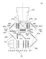
図1は、本発明の第1実施形態に係る液晶装置である液晶ライトバルブ(光変調装置)の構造を説明する拡大断面図である。
[First Embodiment]
FIG. 1 is an enlarged cross-sectional view illustrating the structure of a liquid crystal light valve (light modulation device) that is a liquid crystal device according to a first embodiment of the present invention.

図示の液晶ライトバルブ31において、入射側の偏光素子である第1偏光フィルタ31bと、射出側の偏光素子である第2偏光フィルタ31cとは、クロスニコルを構成する。これら第1及び第2偏光フィルタ31b,31cの間に挟まれた液晶装置31aは、入射光の偏光方向を入力信号に応じて画素単位で変化させる透過型の液晶パネルである。なお、偏光フィルタ31b,31cは、樹脂等で形成される吸収型の偏光子とすることもできるが、ワイヤグリッド偏光子等の反射型の偏光子とすることもできる。   In the liquid crystal light valve 31 shown in the figure, the first polarizing filter 31b that is the polarizing element on the incident side and the second polarizing filter 31c that is the polarizing element on the exit side form a crossed Nicol. The liquid crystal device 31a sandwiched between the first and second polarizing filters 31b and 31c is a transmissive liquid crystal panel that changes the polarization direction of incident light in units of pixels according to an input signal. The polarizing filters 31b and 31c can be absorption polarizers made of resin or the like, but can also be reflection polarizers such as wire grid polarizers.

液晶装置31aは、垂直配向モードで動作する液晶(すなわち垂直配向型の液晶)で構成される液晶層71を挟んで、入射側に透明な第1基板72aと、射出側に透明な第2基板72bとを備える。さらに、液晶装置31aは、入射側透明基板である第1基板72aの外側に入射側カバー74aを備え、射出側透明基板である第2基板72bの外側に射出側カバー74bを備える。   The liquid crystal device 31a includes a first substrate 72a that is transparent on the incident side and a second substrate that is transparent on the emission side, with a liquid crystal layer 71 composed of liquid crystal operating in the vertical alignment mode (that is, vertical alignment type liquid crystal). 72b. Further, the liquid crystal device 31a includes an incident side cover 74a outside the first substrate 72a, which is an incident side transparent substrate, and an emission side cover 74b, outside the second substrate 72b, which is an emission side transparent substrate.

第1基板72aの液晶層71側の面上には、透明な共通電極75が設けられており、その上には、例えば配向膜76が形成されている。一方、第2基板72bの液晶層71側の面上には、マトリクス状に配置された複数の透明画素電極77と、各透明画素電極77に電気的に接続されている薄膜トランジスタ(不図示)とが設けられており、その上には、例えば配向膜78が形成されている。ここで、第1及び第2基板72a,72bと、これらに挟まれた液晶層71と、電極75,77とは、入射光の偏光状態を変化させるための液晶セルとなっている。また、液晶セルを構成する各画素は、1つの画素電極77と、共通電極75と、これらの間に挟まれた液晶層71とを含む。なお、第1基板72aと共通電極75との間には、各画素を区分するように格子状のブラックマトリックス79が設けられている。   A transparent common electrode 75 is provided on the surface of the first substrate 72a on the liquid crystal layer 71 side, and an alignment film 76 is formed thereon, for example. On the other hand, on the surface of the second substrate 72b on the liquid crystal layer 71 side, there are a plurality of transparent pixel electrodes 77 arranged in a matrix and thin film transistors (not shown) electrically connected to the transparent pixel electrodes 77. And an alignment film 78 is formed thereon, for example. Here, the first and second substrates 72a and 72b, the liquid crystal layer 71 sandwiched therebetween, and the electrodes 75 and 77 form a liquid crystal cell for changing the polarization state of incident light. Each pixel constituting the liquid crystal cell includes one pixel electrode 77, a common electrode 75, and a liquid crystal layer 71 sandwiched therebetween. A grid-like black matrix 79 is provided between the first substrate 72a and the common electrode 75 so as to partition each pixel.

ここで、配向膜76,78は、液晶層71を構成する液晶すなわち液晶性化合物を必要な方向に配列させるためのものであり、液晶層71に電圧が印加されないオフ状態において、液晶性化合物の光学軸を第1基板72aの法線に対して大きくないが一様な傾きとなるように配向させる役割を有し、液晶層71に電圧が印加されたオン状態において、液晶性化合物の光学軸を第1基板72aの法線に対して垂直な特定の方向(具体的にはX方向)に配向させる役割を有する。これにより、液晶層71に対して電圧を印加しないオフ状態において、最大遮光状態(最低輝度状態)を確保することができ、液晶層71に対して電圧を印可したオン状態において、最大透過状態(最高輝度状態)を確保することができる。   Here, the alignment films 76 and 78 are for aligning the liquid crystal constituting the liquid crystal layer 71, that is, the liquid crystal compound in a necessary direction, and in the off state where no voltage is applied to the liquid crystal layer 71, The optical axis serves to align the optical axis so that it is not large but has a uniform inclination with respect to the normal line of the first substrate 72a, and in the ON state where a voltage is applied to the liquid crystal layer 71, the optical axis of the liquid crystal compound Is oriented in a specific direction (specifically, the X direction) perpendicular to the normal line of the first substrate 72a. Thus, the maximum light-shielding state (minimum luminance state) can be secured in the off state in which no voltage is applied to the liquid crystal layer 71, and the maximum transmission state (in the on state in which the voltage is applied to the liquid crystal layer 71). (Highest luminance state) can be secured.

この液晶装置31aにおいて、入射側カバー74aの入射面すなわち第1偏光フィルタ31bに対向する一方の平坦面には、薄い第1複屈折部材73aが貼り付けられている。また、入射側カバー74aと第1基板72aとの間には、薄い第2複屈折部材73bが挿入されている。ここで、第1複屈折部材73aや第2複屈折部材73bは、光学接着剤によって入射側カバー74aの両平坦面上に接合されて一体化した方位角補償部材OC1を構成しており、このような方位角補償部材OC1は、第1基板72aの入射面上に光学接着剤によって貼り付けられる。第1及び第2複屈折部材73a,73bは、例えば正の一軸結晶である水晶等の複屈折材料でそれぞれ形成されている。なお、方位角補償部材OC1は、後に詳述するが、オフ状態の液晶層71による位相変調量に対してその方位角依存性を相殺するように作用する。これにより、方位角補償部材OC1とオフ状態の液晶層71とを合わせた全体が、入射軸すなわちZ軸に沿った光学軸を有する擬似的な正の一軸結晶と同様の複屈折材料として機能することになる。
なお、方位角補償部材OC1については、第1及び第1複屈折部材73a,73bのみで構成することができる。その場合、入射側カバー74aは不要になり、両複屈折部材73a,73bを直接第1基板72aに貼り付けることができ、或いは両複屈折部材73a,73bを適当なホルダによって第1基板72aから離間して保持させることもできる。
In the liquid crystal device 31a, a thin first birefringent member 73a is attached to the incident surface of the incident side cover 74a, that is, one flat surface facing the first polarizing filter 31b. A thin second birefringent member 73b is inserted between the incident side cover 74a and the first substrate 72a. Here, the first birefringent member 73a and the second birefringent member 73b constitute an azimuth compensating member OC1 which is joined and integrated on both flat surfaces of the incident side cover 74a by an optical adhesive, Such an azimuth compensation member OC1 is attached to the incident surface of the first substrate 72a by an optical adhesive. The first and second birefringent members 73a and 73b are each formed of a birefringent material such as quartz that is a positive uniaxial crystal. As will be described in detail later, the azimuth compensation member OC1 acts to cancel the azimuth dependency on the phase modulation amount by the liquid crystal layer 71 in the off state. Thereby, the whole of the azimuth compensation member OC1 and the liquid crystal layer 71 in the off state functions as a birefringent material similar to a pseudo positive uniaxial crystal having an optical axis along the incident axis, that is, the Z axis. It will be.
Note that the azimuth angle compensation member OC1 can be configured by only the first and first birefringent members 73a and 73b. In that case, the incident side cover 74a becomes unnecessary, and both the birefringent members 73a and 73b can be directly attached to the first substrate 72a, or both the birefringent members 73a and 73b can be attached from the first substrate 72a by an appropriate holder. It can also be held apart.

一方、射出側カバー74bの射出面すなわち第2偏光フィルタ31cに対向する一方の平坦面には、例えばサファイアであれば150〜250μm程度の厚さを有する薄い第3複屈折部材73dが貼り付けられている。ここで、第3複屈折部材73dは、光学接着剤によって射出側カバー74bの片平坦面上に接合されて一体化した極角補償部材OC2を構成しており、このような極角補償部材OC2は、第2基板72bの射出面上に光学接着剤によって貼り付けられる。第3複屈折部材73dは、例えば負の一軸結晶であるサファイア等の複屈折材料で形成されている。なお、極角補償部材OC2は、後に詳述するが、オフ状態の液晶層71と方位角補償部材OC1とによって生じる複合的作用としての位相変調量に関して極角依存性を相殺するように作用する。これにより、方位角補償部材OC1とオフ状態の液晶層71とを合わせた擬似的な正の一軸結晶型の複屈折性と、極角補償部材OC2の負の一軸結晶型の複屈折性とが組み合わさって、全体として入射光の方位角や極角に応じて位相変調量が変化しにくい高精度の液晶装置31aが得られる。
なお、極角補償部材OC2については、第3複屈折部材73dのみで構成することができる。その場合、射出側カバー74bは不要になり、第3複屈折部材73dを直接第2基板72bに貼り付けることができ、或いは第3複屈折部材73dを適当なホルダによって第2基板72bから離間して保持させることもできる。
On the other hand, a thin third birefringent member 73d having a thickness of about 150 to 250 μm is attached to the exit surface of the exit side cover 74b, that is, one flat surface facing the second polarizing filter 31c. ing. Here, the third birefringent member 73d constitutes a polar angle compensating member OC2 which is joined and integrated on the one flat surface of the exit side cover 74b with an optical adhesive, and such a polar angle compensating member OC2 is formed. Is affixed to the emission surface of the second substrate 72b with an optical adhesive. The third birefringent member 73d is formed of a birefringent material such as sapphire, which is a negative uniaxial crystal, for example. As will be described in detail later, the polar angle compensation member OC2 acts to cancel the polar angle dependency with respect to the phase modulation amount as a combined action caused by the liquid crystal layer 71 in the off state and the azimuth angle compensation member OC1. . Thereby, a pseudo positive uniaxial crystal type birefringence combining the azimuth angle compensation member OC1 and the off-state liquid crystal layer 71 and a negative uniaxial crystal type birefringence of the polar angle compensation member OC2 are obtained. In combination, a high-accuracy liquid crystal device 31a is obtained in which the amount of phase modulation hardly changes according to the azimuth angle or polar angle of incident light as a whole.
Note that the polar angle compensation member OC2 can be configured by only the third birefringent member 73d. In that case, the exit side cover 74b is not necessary, and the third birefringent member 73d can be directly attached to the second substrate 72b, or the third birefringent member 73d can be separated from the second substrate 72b by an appropriate holder. Can also be held.

図2は、図1に示す液晶層71の屈折率と両補償部材OC1,OC2の屈折率とを説明する側方断面の概念図である。また、図3(a)は、図1に示す液晶層71及び方位角補償部材OC1の屈折率を概念的に説明する平面図であり、図3(b)は、液晶層71及び方位角補償部材OC1の複合的屈折率を概念的に説明する平面図であり、図3(c)は、図1に示す液晶層71及び方位角補償部材OC1の複合的屈折率と極角補償部材OC2の屈折率を概念的に説明する側面図である。ここで、方位角補償部材OC1を構成する第1及び第2複屈折部材73a,73bと、オフ状態の液晶層71の画素部分と、極角補償部材OC2を構成する第3複屈折部材73dとは、すべて平行な入出射面に挟まれており、互いに平行に配置されている。ただし、光学的性能に実質的な影響を与えない範囲で、上記の各要素自体や相互間に僅かなクサビ角を設けることもできる。   FIG. 2 is a conceptual side sectional view for explaining the refractive index of the liquid crystal layer 71 shown in FIG. 1 and the refractive indexes of both compensation members OC1 and OC2. 3A is a plan view conceptually illustrating the refractive index of the liquid crystal layer 71 and the azimuth angle compensation member OC1 shown in FIG. 1, and FIG. 3B is a plan view illustrating the liquid crystal layer 71 and the azimuth angle compensation. FIG. 3C is a plan view conceptually illustrating the composite refractive index of the member OC1, and FIG. 3C illustrates the composite refractive index of the liquid crystal layer 71 and the azimuth compensation member OC1 and the polar angle compensation member OC2 shown in FIG. It is a side view which illustrates a refractive index conceptually. Here, the first and second birefringence members 73a and 73b constituting the azimuth angle compensation member OC1, the pixel portion of the liquid crystal layer 71 in the off state, the third birefringence member 73d constituting the polar angle compensation member OC2, and Are sandwiched between parallel entrance / exit surfaces and are arranged in parallel to each other. However, it is also possible to provide a slight wedge angle between the above-described elements themselves and each other as long as the optical performance is not substantially affected.

図2の液晶装置31aに入射面S1を介して入射した光束は、第1及び第2複屈折部材73a,73bを順次通過した後に液晶層71を通過し、最終的に第3複屈折部材73dを経て射出面S2から射出される。   The light beam incident on the liquid crystal device 31a of FIG. 2 through the incident surface S1 sequentially passes through the first and second birefringent members 73a and 73b, then passes through the liquid crystal layer 71, and finally the third birefringent member 73d. Through the exit surface S2.

液晶装置31aのうち、液晶層71において、液晶性化合物の屈折率楕円体RIE1の長軸すなわち光学軸OA1は、XZ面内でZ軸すなわち入射軸IAに対して小さいが一定の傾き角を有している。この際、屈折率楕円体RIE1の傾き方向はX方向であり、このX方向を液晶層71の配向方向と呼ぶものとし、XZ面を便宜上第1方位面P1と呼ぶものとする(図3(a)参照)。また、この屈折率楕円体RIE1の配向方向における傾き角は、プレチルト角θ1と呼ばれる。   In the liquid crystal device 31a, in the liquid crystal layer 71, the major axis of the refractive index ellipsoid RIE1 of the liquid crystalline compound, that is, the optical axis OA1, is small with respect to the Z axis, that is, the incident axis IA in the XZ plane, but has a constant tilt angle. is doing. At this time, the tilt direction of the refractive index ellipsoid RIE1 is the X direction, this X direction is called the alignment direction of the liquid crystal layer 71, and the XZ plane is called the first azimuth plane P1 for convenience (FIG. 3 ( a)). The tilt angle in the orientation direction of the refractive index ellipsoid RIE1 is called a pretilt angle θ1.

一方、方位角補償部材OC1の第1複屈折部材73aにおいて、これを構成する正の一軸性の屈折率楕円体RIE2の長軸すなわち光学軸OA2は、入射軸IAに対して適宜傾いた状態に設定されており、XZ面に平行な第1方位面P1を入射軸IAのまわりに反時計方向に120°回転させた第2方位面P2内にある(図3(a)参照)。この際、屈折率楕円体RIE2の第2方位面P2における入射軸IAに対する傾き角θ2すなわち極角は、液晶層71に付与されているプレチルト角θ1と略等しくなっている。   On the other hand, in the first birefringent member 73a of the azimuth compensating member OC1, the long axis of the positive uniaxial refractive index ellipsoid RIE2 that constitutes the first birefringent member 73a, that is, the optical axis OA2 is appropriately inclined with respect to the incident axis IA. The first azimuth plane P1, which is set and parallel to the XZ plane, is in the second azimuth plane P2 rotated by 120 ° counterclockwise around the incident axis IA (see FIG. 3A). At this time, the tilt angle θ2, that is, the polar angle with respect to the incident axis IA in the second azimuth plane P2 of the refractive index ellipsoid RIE2 is substantially equal to the pretilt angle θ1 given to the liquid crystal layer 71.

また、方位角補償部材OC1の第2複屈折部材73bにおいて、これを構成する正の一軸性の屈折率楕円体RIE3の長軸すなわち光学軸OA3は、入射軸IAに対して適宜傾いた状態に設定されており、上記第1方位面P1を入射軸IAのまわりに時計方向に120°回転させた第3方位面P3内にある(図3(a)参照)。この際、屈折率楕円体RIE3の第3方位面P3における入射軸IAに対する傾き角θ3すなわち極角は、液晶層71に付与されているプレチルト角θ1と略等しくなっている。   Further, in the second birefringent member 73b of the azimuth compensating member OC1, the long axis of the positive uniaxial refractive index ellipsoid RIE3 constituting the second birefringent member 73b, that is, the optical axis OA3 is appropriately inclined with respect to the incident axis IA. It is set and is in the third azimuth plane P3 obtained by rotating the first azimuth plane P1 clockwise by 120 ° around the incident axis IA (see FIG. 3A). At this time, the tilt angle θ3, that is, the polar angle with respect to the incident axis IA in the third azimuth plane P3 of the refractive index ellipsoid RIE3 is substantially equal to the pretilt angle θ1 given to the liquid crystal layer 71.

以上説明したオフ状態の液晶層71を表す屈折率楕円体RIE1の作用と、第1複屈折部材73aを表す屈折率楕円体RIE2の作用と、第2複屈折部材73bを表す屈折率楕円体RIE3の作用とを加算すると、擬似的に正の一軸性の複屈折材料と等価な複合的作用を達成することができる。つまり、図3(b)に示すように、上記のような複合的作用を達成する擬似的な複屈折材料の屈折率楕円体QEは、XY面内において略円形の屈折率断面を有し、図3(c)に示すように、同屈折率楕円体QEは、XZ面内において楕円の屈折率断面を有する。図からも明らかなように、屈折率楕円体QEは、Z軸方向すなわち入射軸IA方向を長軸としており、入射軸IAに沿った光学軸OA4を有する正の一軸性の複屈折材料と等価な屈折率異方性を示す。   The refractive index ellipsoid RIE1 representing the liquid crystal layer 71 in the off state, the refractive ellipsoid RIE2 representing the first birefringent member 73a, and the refractive ellipsoid RIE3 representing the second birefringent member 73b described above. In addition, it is possible to achieve a composite action equivalent to that of a pseudo positive uniaxial birefringent material. That is, as shown in FIG. 3B, the refractive index ellipsoid QE of the pseudo birefringent material that achieves the above-described composite action has a substantially circular refractive index section in the XY plane. As shown in FIG. 3C, the refractive index ellipsoid QE has an elliptical refractive index cross section in the XZ plane. As is clear from the figure, the refractive index ellipsoid QE is equivalent to a positive uniaxial birefringent material having the long axis in the Z-axis direction, that is, the incident axis IA direction, and the optical axis OA4 along the incident axis IA. Refractive index anisotropy is exhibited.

図4(a)は、液晶層71の屈折率楕円体RIE1と、第1複屈折部材73aの屈折率楕円体RIE2と、第2複屈折部材73bの屈折率楕円体RIE3との関係を説明する斜視図である。また、図4(b)は、3つの屈折率楕円体RIE1,RIE2,RIE3の作用、すなわちこれら屈折率楕円体RIE1,RIE2,RIE3の作用を合成した複合な屈折率楕円体QEを表す斜視図である。図からも明らかなように、3つのラグビーボール状の屈折率楕円体RIE1,RIE2,RIE3を組み合わせることによって、1つの擬似的な屈折率楕円体QEが得られることが分かる。   FIG. 4A illustrates the relationship between the refractive index ellipsoid RIE1 of the liquid crystal layer 71, the refractive index ellipsoid RIE2 of the first birefringent member 73a, and the refractive index ellipsoid RIE3 of the second birefringent member 73b. It is a perspective view. FIG. 4B is a perspective view showing a composite refractive index ellipsoid QE obtained by synthesizing the actions of the three refractive index ellipsoids RIE1, RIE2, and RIE3, that is, the actions of these refractive index ellipsoids RIE1, RIE2, and RIE3. It is. As is apparent from the figure, it is understood that one pseudo refractive index ellipsoid QE can be obtained by combining three rugby ball-shaped refractive index ellipsoids RIE1, RIE2, and RIE3.

以上では、液晶層71の屈折率楕円体RIE1と、第1複屈折部材73aの屈折率楕円体RIE2と、第2複屈折部材73bの屈折率楕円体RIE3が略等しいサイズを有し、液晶層71と第1複屈折部材73aと第2複屈折部材73bとが等しい厚みを有するものとして説明を行った。しかしながら、通常、液晶層71と複屈折部材73a、73bとの屈折率は異なっており、各屈折率楕円体RIE1,RIE2,RIE3のサイズすなわち屈折率と、速軸方向の屈折率と遅軸方向の屈折率との屈折率差とが異なる場合を考慮する必要がある。   In the above, the refractive index ellipsoid RIE1 of the liquid crystal layer 71, the refractive index ellipsoid RIE2 of the first birefringent member 73a, and the refractive index ellipsoid RIE3 of the second birefringent member 73b have substantially the same size, and the liquid crystal layer In the description, 71, the first birefringent member 73a, and the second birefringent member 73b have the same thickness. However, the refractive index of the liquid crystal layer 71 and the birefringent members 73a and 73b are usually different, and the size of each refractive index ellipsoid RIE1, RIE2, RIE3, that is, the refractive index in the fast axis direction and the slow axis direction. It is necessary to consider the case where the difference in refractive index from the refractive index is different.

液晶層71、第1複屈折部材73a及び第2複屈折部材73bにおいて、各屈折率及び速軸方向の屈折率と遅軸方向の屈折率との屈折率差とが異なる場合には、それぞれの光学軸の極角が決定され、厚さはその極角、各屈折率差などによって方位角依存性がなくなるように最適化する。   In the liquid crystal layer 71, the first birefringent member 73a and the second birefringent member 73b, when the refractive index and the refractive index difference between the refractive index in the fast axis direction and the refractive index in the slow axis direction are different, The polar angle of the optical axis is determined, and the thickness is optimized so that the dependence on the azimuth angle is eliminated by the polar angle, each refractive index difference, and the like.

まず、図5に示すように、液晶層71、第1複屈折部材73a及び第2複屈折部材73bの光学軸がすべて同じ方向に(同じ方位角で)傾斜しており、さらに液晶層71→第1複屈折部材73a→第2複屈折部材73bの順番に光が透過すると想定する。液晶層71、第1複屈折部材73a及び第2複屈折部材73bの各光入射面及び光射出面はすべて平行である。液晶層71の光入射面に対して入射角θ1°で入射してくる光は始めに液晶層71の光入射面で屈折し、液晶層71中では屈折角θ2°で進行する。ここで、屈折角θ2°で進む光と液晶層71内の液晶の光学軸とのなす角度をα°とする。次に、液晶層71から出射し屈折角θ1°(液晶層71の光入射面への入射角に同じ)で進行し、第1複屈折部材73aへ入射する。第1複屈折部材73aの光入射面で屈折した光は、第1複屈折部材73a内を屈折角θ3°で進行する。ここで、屈折角θ3°で進む光と第1複屈折部材73aの光学軸とのなす角度がα°(液晶層71内を進む光と液晶の光学軸がなす角度α°に同じ)となるように、第1複屈折部材73aの光学軸の傾き(極角)を決定する。同様に、第2複屈折部材73bを屈折角θ4°で進む光と第2複屈折部材73bの光学軸とのなす角度がα°(液晶層71内を進む光と液晶の光学軸がなす角度α°に同じ)となるように、第2複屈折部材73bの光学軸の傾き(極角)を決定する。屈折角θ2°、θ3°及びθ4°は液晶層71、第1複屈折部材73aの各屈折率とそれらの間に介在する物質の屈折率により決定される。   First, as shown in FIG. 5, the optical axes of the liquid crystal layer 71, the first birefringent member 73a, and the second birefringent member 73b are all inclined in the same direction (with the same azimuth angle), and the liquid crystal layer 71 → It is assumed that light is transmitted in the order of the first birefringent member 73a → the second birefringent member 73b. The light incident surfaces and the light exit surfaces of the liquid crystal layer 71, the first birefringent member 73a, and the second birefringent member 73b are all parallel. Light incident on the light incident surface of the liquid crystal layer 71 at an incident angle θ1 ° is first refracted at the light incident surface of the liquid crystal layer 71 and travels in the liquid crystal layer 71 at a refraction angle θ2 °. Here, the angle between the light traveling at the refraction angle θ2 ° and the optical axis of the liquid crystal in the liquid crystal layer 71 is α °. Next, the light is emitted from the liquid crystal layer 71, travels at a refraction angle θ1 ° (same as the incident angle on the light incident surface of the liquid crystal layer 71), and enters the first birefringent member 73a. The light refracted on the light incident surface of the first birefringent member 73a travels within the first birefringent member 73a at a refraction angle θ3 °. Here, the angle formed by the light traveling at the refraction angle θ3 ° and the optical axis of the first birefringent member 73a is α ° (the same as the angle α ° formed by the light traveling in the liquid crystal layer 71 and the optical axis of the liquid crystal). Thus, the inclination (polar angle) of the optical axis of the first birefringent member 73a is determined. Similarly, the angle formed between the light traveling through the second birefringent member 73b at a refraction angle θ4 ° and the optical axis of the second birefringent member 73b is α ° (the angle formed between the light traveling through the liquid crystal layer 71 and the optical axis of the liquid crystal). The inclination (polar angle) of the optical axis of the second birefringent member 73b is determined so as to be equal to α °. The refraction angles θ2 °, θ3 °, and θ4 ° are determined by the refractive indexes of the liquid crystal layer 71 and the first birefringent member 73a and the refractive index of the substance interposed therebetween.

この様に光学軸の極角が決定された液晶層71、第1複屈折部材73a及び第2複屈折部材73bをそれぞれの方位角が互いに120°ずつずれるように配置する。   The liquid crystal layer 71, the first birefringent member 73a, and the second birefringent member 73b in which the polar angle of the optical axis is determined in this way are arranged so that the respective azimuths are shifted from each other by 120 °.

次に、第1複屈折部材73a及び第2複屈折部材73bの各厚みを決定する。第1複屈折部材73aと第2複屈折部材73bとの屈折率が大きく異なると、ある一つの入射角の光線を考えただけで厚さは決定できない。実際は、なるべく方位角依存性がなくなるようにシミュレーション上で厚さを少しずつ変化させていき、最もリタデーションの小さくなる厚みを選定する。   Next, the thicknesses of the first birefringent member 73a and the second birefringent member 73b are determined. If the refractive indexes of the first birefringent member 73a and the second birefringent member 73b are greatly different, the thickness cannot be determined only by considering a light beam having a certain incident angle. Actually, the thickness is gradually changed in the simulation so as to eliminate the azimuth angle dependency as much as possible, and the thickness with the smallest retardation is selected.

なお、特別な場合として、液晶層71、第1複屈折部材73a及び第2複屈折部材73bの各屈折率がおよそ等しい場合は、各屈折率差と厚さは以下のような関係になる。
Δn(液晶層71の屈折率)×D(液晶層71の厚み)
=Δn(第1複屈折部材73aの屈折率)×D(第1複屈折部材73aの厚み)
=Δn(第2複屈折部材73bの屈折率)×D(第2複屈折部材73bの厚み)
As a special case, when the refractive indexes of the liquid crystal layer 71, the first birefringent member 73a, and the second birefringent member 73b are approximately equal, the refractive index difference and the thickness have the following relationship.
Δn (the refractive index of the liquid crystal layer 71) × D (the thickness of the liquid crystal layer 71)
= Δn (refractive index of first birefringent member 73a) × D (thickness of first birefringent member 73a)
= Δn (refractive index of second birefringent member 73b) × D (thickness of second birefringent member 73b)

極角補償部材OC2の第3複屈折部材73dにおいては、図3(c)に示すように、第3複屈折部材73dを構成する負の一軸結晶の屈折率楕円体RIE5の短軸すなわち光学軸OA5が入射軸IAに対して平行に設定されている。一方で、既に説明したように、オフ状態の液晶層71と第1複屈折部材73aと第2複屈折部材73bとを組み合わせて得られる作用に等価とみなされる屈折率楕円体QEは、長軸すなわち光学軸OA4が入射軸IAに対して平行に設定されている。ここで、第3複屈折部材73dにおける屈折率楕円体RIE5の複屈折量すなわち速軸方向の屈折率と遅軸方向の屈折率との屈折率差と第3複屈折部材73dの厚さから計算される位相変調量と、液晶層71等を合わせた屈折率楕円体QEの複屈折量すなわち速軸方向の屈折率と遅軸方向の屈折率との屈折率差と液晶層71、第1複屈折部材73a及び第2複屈折部材73bの厚さから計算される位相変調量が略等しければ、方位角補償部材OC1と、オフ状態の液晶層71と、極角補償部材OC2とを順次経た光束は、恰も等方性の材料を通過するかのように振る舞う。つまり、液晶装置31aに入射した照明光については、方位角補償部材OC1によって、入射軸IAのまわりにおける方位角に依存する位相差が近似的に補償され、極角補償部材OC2によって、入射軸IAに対する極角に依存する位相差が補償される。よって、入射軸IAに対して比較的小さな角度から大きな角度で入射する様々な照明光が、入射軸IAに沿った照明光と略等価な作用を受けることになり、液晶ライトバルブ31の視野角特性が入射軸IAに関して対称的になるとともに、液晶ライトバルブ31の液晶セルに電圧を印可しないオフ時すなわち黒表示時における正面方向の遮光性を高めることができ、液晶ライトバルブ31のコントラストを向上させることができる。   In the third birefringent member 73d of the polar angle compensating member OC2, as shown in FIG. 3C, the short axis, that is, the optical axis, of the negative uniaxial crystal refractive index ellipsoid RIE5 constituting the third birefringent member 73d. OA5 is set parallel to the incident axis IA. On the other hand, as already described, the refractive index ellipsoid QE regarded as equivalent to the action obtained by combining the liquid crystal layer 71 in the off state, the first birefringent member 73a, and the second birefringent member 73b has a long axis That is, the optical axis OA4 is set parallel to the incident axis IA. Here, the birefringence amount of the refractive index ellipsoid RIE5 in the third birefringent member 73d, that is, the refractive index difference between the refractive index in the fast axis direction and the refractive index in the slow axis direction, and the thickness of the third birefringent member 73d are calculated. The phase modulation amount and the birefringence amount of the refractive index ellipsoid QE including the liquid crystal layer 71 and the like, that is, the refractive index difference between the refractive index in the fast axis direction and the refractive index in the slow axis direction, and the liquid crystal layer 71 If the phase modulation amounts calculated from the thicknesses of the refracting member 73a and the second birefringent member 73b are substantially equal, the light beam sequentially passes through the azimuth angle compensating member OC1, the off-state liquid crystal layer 71, and the polar angle compensating member OC2. Behaves as if it passes through isotropic material. That is, for the illumination light incident on the liquid crystal device 31a, the phase difference depending on the azimuth angle around the incident axis IA is approximately compensated by the azimuth compensation member OC1, and the incident axis IA is compensated by the polar angle compensation member OC2. The phase difference depending on the polar angle with respect to is compensated. Therefore, various illumination lights incident at a relatively small angle to a large angle with respect to the incident axis IA are subjected to substantially the same action as the illumination light along the incident axis IA, and the viewing angle of the liquid crystal light valve 31 The characteristic becomes symmetric with respect to the incident axis IA, and the light shielding property in the front direction when the voltage is not applied to the liquid crystal cell of the liquid crystal light valve 31 in the off state, that is, when displaying black, can be improved, and the contrast of the liquid crystal light valve 31 is improved. Can be made.

図6(a)は、液晶層71、第1複屈折部材73a及び第2複屈折部材73bのそれぞれの屈折率楕円体RIE1,RIE2,RIE3を合成した屈折率楕円体QEを示し、図6(b)は、第3複屈折部材73dの屈折率楕円体RIE5を示す。また、図6(c)は、屈折率楕円体QEと屈折率楕円体RIE5との作用を合成した複合的な屈折率球体RISを表す斜視図である。屈折率楕円体QEと屈折率楕円体RIE5とは、光学軸OA4,OA5がともにZ軸方向に平行で、正負が異なる一軸結晶型の特性を有するので、積算によって恰も等方性の材料のように振る舞わせることが可能になる。   FIG. 6A shows a refractive index ellipsoid QE obtained by synthesizing the refractive index ellipsoids RIE1, RIE2, and RIE3 of the liquid crystal layer 71, the first birefringent member 73a, and the second birefringent member 73b. b) shows the refractive index ellipsoid RIE5 of the third birefringent member 73d. FIG. 6C is a perspective view showing a composite refractive index sphere RIS in which the actions of the refractive index ellipsoid QE and the refractive index ellipsoid RIE5 are combined. Since the refractive index ellipsoid QE and the refractive index ellipsoid RIE5 have uniaxial crystal type characteristics in which the optical axes OA4 and OA5 are both parallel to the Z-axis direction and are different from each other in positive and negative directions, Can be made to act.

以上では、合成の対象となる屈折率楕円体QEと、極角補償用の屈折率楕円体RIE5とが略等しいサイズを有するものとしているが、屈折率楕円体QEのサイズと屈折率楕円体RIE5のサイズとは通常異なる。よって、方位角補償部材OC1の場合と同様に、極角補償部材OC2の入射軸IAすなわちZ軸方向の厚みを調整することによって、屈折率楕円体QEの作用によって生じる位相変調量と屈折率楕円体RIE5の作用によって生じる位相変調量とをバランスさせることができるので、入射軸IAに対する傾きとしての極角に依存する光変調の差を殆どなくすことができる。   In the above description, the refractive index ellipsoid QE to be synthesized and the refractive index ellipsoid RIE5 for polar angle compensation have substantially the same size. However, the size of the refractive index ellipsoid QE and the refractive index ellipsoid RIE5 are the same. Usually different from the size. Therefore, as in the case of the azimuth compensation member OC1, the phase modulation amount and the refractive index ellipse generated by the action of the refractive index ellipsoid QE are adjusted by adjusting the thickness of the polar angle compensation member OC2 in the incident axis IA, that is, the Z-axis direction. Since the phase modulation amount generated by the action of the body RIE5 can be balanced, a difference in light modulation depending on the polar angle as the inclination with respect to the incident axis IA can be almost eliminated.

具体的な実施例について説明すると、垂直配向型の各種液晶層71に対して、方位角補償部材OC1を構成する第1及び第2複屈折部材73a,73bとして水晶を用いた場合、各複屈折部材73a,73bの厚みは、30〜40μm程度の範囲となった。また、同じ条件で、極角補償部材OC2を構成する第3複屈折部材73dとしてサファイア結晶を用いた場合、第3複屈折部材73dの厚みは、100〜300μm程度の範囲となった。   A specific example will be described. When the quartz is used as the first and second birefringence members 73a and 73b constituting the azimuth angle compensation member OC1 for the various liquid crystal layers 71 of the vertical alignment type, each birefringence is obtained. The thickness of the members 73a and 73b was in the range of about 30 to 40 μm. Moreover, when the sapphire crystal was used as the third birefringent member 73d constituting the polar angle compensating member OC2 under the same conditions, the thickness of the third birefringent member 73d was in the range of about 100 to 300 μm.

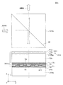
図7は、具体的な液晶ライトバルブ31に対応するデータでシミュレーションを行った結果を示す。図7(a)は、実施例の液晶ライトバルブ31の視野角特性を示し、図7(b)は、比較例の液晶ライトバルブの視野角特性を示す。比較例の液晶ライトバルブは、実施例の液晶ライトバルブ31から両補償部材OC1,OC2を除いたものである。両視野角特性において、等高線は、入射面の法線方向に対する傾斜角を意味する。図からも明らかなように、実施例の液晶ライトバルブ31の場合、視野角特性が入射面の法線方向に関して対称的であり、液晶ライトバルブ31の正面方向のコントラストを著しく向上させていることが分かる。   FIG. 7 shows the result of simulation using data corresponding to a specific liquid crystal light valve 31. FIG. 7A shows the viewing angle characteristics of the liquid crystal light valve 31 of the example, and FIG. 7B shows the viewing angle characteristics of the liquid crystal light valve of the comparative example. The liquid crystal light valve of the comparative example is obtained by removing both compensation members OC1 and OC2 from the liquid crystal light valve 31 of the embodiment. In both viewing angle characteristics, the contour line means an inclination angle with respect to the normal direction of the incident surface. As is apparent from the figure, in the case of the liquid crystal light valve 31 of the embodiment, the viewing angle characteristics are symmetrical with respect to the normal direction of the incident surface, and the contrast in the front direction of the liquid crystal light valve 31 is remarkably improved. I understand.

以下、第1及び第2複屈折部材73a,73bを備える方位角補償部材OC1の製造方法について説明する。まず、方位角補償部材OC1の構成要素となる、一対の複屈折部材73a,73b及び入射側カバー74aの材料を準備する。すなわち、第1及び第2複屈折部材73a,73bの材料となる水晶等をなるべく薄く切り出して、光学軸すなわち各屈折率楕円体RIE1,RIE2の傾き方向と傾き角とが図2及び図3(a)に示すようなものになるようにする。次に、切り出した各水晶板の一対の対向する平面に対して研磨等の加工を施して表面を滑らかにする。次に、入射側カバー74aの材料となる、石英、白板ガラス等の透過率が高く複屈折性有しない平行平板状の支持基板を準備する。次に、洗浄後の支持基板の表面側に紫外線硬化樹脂を介して洗浄後の一方の水晶板をアライメントして貼り合わせた後、硬化によって固定する。次に、支持基板の裏面側に紫外線硬化樹脂を介して洗浄後の他方の水晶板をアライメントして貼り合わせた後、硬化によって固定する。その後、支持基板上の両水晶板を比較的粗い砥粒で研磨して、水晶板が必要な厚さの第1及び第2複屈折部材73a,73bになるようにする。仕上げとして、研磨された面には細かい傷がつくので、両複屈折部材73a,73bと同程度の屈折率を有する接着材等で傷を埋め、或いは比較的細かい砥粒で再度研磨を行って、両複屈折部材73a,73bの表面を平滑化する。なお、第1及び第2複屈折部材73a,73bにおいて割れ等に耐えうる厚みである場合は、入射側カバー74aを介在させずに第1及び第2複屈折部材73a,73bを直接接着固定し加工を施してもよい。   Hereinafter, a method for manufacturing the azimuth compensating member OC1 including the first and second birefringent members 73a and 73b will be described. First, materials for the pair of birefringent members 73a and 73b and the incident side cover 74a, which are constituent elements of the azimuth compensation member OC1, are prepared. That is, the quartz and the like used as the material of the first and second birefringent members 73a and 73b are cut out as thin as possible, and the tilt directions and tilt angles of the optical axes, that is, the refractive index ellipsoids RIE1 and RIE2, are shown in FIGS. It should be as shown in a). Next, a process such as polishing is performed on a pair of opposed flat surfaces of each cut crystal plate to smooth the surface. Next, a parallel flat support substrate having a high transmittance, such as quartz or white plate glass, which is a material of the incident side cover 74a and having no birefringence is prepared. Next, one quartz plate after washing is aligned and bonded to the surface side of the washed support substrate via an ultraviolet curable resin, and then fixed by curing. Next, the other crystal plate after cleaning is aligned and bonded to the back surface side of the support substrate through an ultraviolet curable resin, and then fixed by curing. Thereafter, both quartz plates on the support substrate are polished with relatively coarse abrasive grains so that the quartz plates become the first and second birefringent members 73a and 73b having a necessary thickness. As the finish, fine scratches are made on the polished surface, so that the scratches are filled with an adhesive having the same refractive index as that of the birefringent members 73a and 73b, or polished again with relatively fine abrasive grains. The surfaces of the birefringent members 73a and 73b are smoothed. If the first and second birefringent members 73a and 73b are thick enough to withstand cracks, the first and second birefringent members 73a and 73b are directly bonded and fixed without the incident side cover 74a interposed. Processing may be performed.

以下、第3複屈折部材73dを備える極角補償部材OC2の製造方法について説明する。まず、極角補償部材OC2の構成要素となる、第3複屈折部材73d及び射出側カバー74bの材料を準備する。すなわち、第3複屈折部材73dの材料となるサファイア等をなるべく薄く切り出して、屈折率楕円体RIE5の光学軸OA5が図3(b)、3(c)に示すようなものになるようにする。次に、切り出したサファイア板の一対の対向する平面に対して研磨等の加工を施して表面を滑らかにする。次に、射出側カバー74bの材料となる、石英、白板ガラス等の透過率が高く複屈折性有しない平行平板状の支持基板を準備する。次に、洗浄後の支持基板の表面側に紫外線硬化樹脂を介して洗浄後のサファイア板を貼り合わせた後、硬化によって固定する。その後、支持基板上のサファイア板を比較的粗い砥粒で研磨して、サファイア板が必要な厚さの第3複屈折部材73dになるようにする。仕上げとして、第3複屈折部材73dと同程度の屈折率を有する接着材等で第3複屈折部材73d表面の傷を埋め、或いは比較的細かい砥粒で再度研磨を行って、第3複屈折部材73dの表面を平滑化する。なお、第3複屈折部材73dにおいて割れ等に耐えうる厚みである場合は、射出側カバー74bに接着せずに第3複屈折部材73d単品で加工を施してもよい。   Hereinafter, a method for manufacturing the polar angle compensating member OC2 including the third birefringent member 73d will be described. First, materials for the third birefringent member 73d and the emission side cover 74b, which are constituent elements of the polar angle compensation member OC2, are prepared. That is, sapphire or the like that is the material of the third birefringent member 73d is cut out as thin as possible so that the optical axis OA5 of the refractive index ellipsoid RIE5 becomes as shown in FIGS. 3 (b) and 3 (c). . Next, a process such as polishing is performed on a pair of opposed planes of the cut sapphire plate to smooth the surface. Next, a parallel plate-like support substrate having a high transmittance such as quartz or white glass, which is a material of the emission side cover 74b, and having no birefringence is prepared. Next, the cleaned sapphire plate is bonded to the surface side of the cleaned support substrate via an ultraviolet curable resin, and then fixed by curing. Thereafter, the sapphire plate on the support substrate is polished with relatively coarse abrasive grains so that the sapphire plate becomes the third birefringent member 73d having a necessary thickness. As finishing, the surface of the third birefringent member 73d is filled with an adhesive or the like having the same refractive index as that of the third birefringent member 73d, or is polished again with relatively fine abrasive grains. The surface of the member 73d is smoothed. If the third birefringent member 73d has a thickness that can withstand cracks or the like, the third birefringent member 73d may be processed without being bonded to the exit side cover 74b.

〔第2実施形態〕
以下、本発明の第2実施形態に係る液晶装置である液晶ライトバルブ(光変調装置)について説明する。第2実施形態の液晶ライトバルブは、第1実施形態の液晶ライトバルブを変形したものであり、特に説明しない部分は、第1実施形態と同様であり重複説明を省略する。
[Second Embodiment]
Hereinafter, a liquid crystal light valve (light modulation device) which is a liquid crystal device according to a second embodiment of the present invention will be described. The liquid crystal light valve of the second embodiment is a modification of the liquid crystal light valve of the first embodiment, and portions that are not specifically described are the same as those of the first embodiment, and redundant description is omitted.

図8は、第2実施形態の液晶ライトバルブに組み込まれる液晶装置31aの構造を説明する側方断面図である。この場合、極角補償部材OC2を構成する第3複屈折部材173dが4枚の部分板81,82,83,84を貼り合わせたものとなっている。これらの部分板81,82,83,84は、いずれも正の一軸性の複屈折材料で作製されている。正の一軸性の複屈折材料を複数枚用いて、負の一軸性材料と同様の特性を得るためには、それぞれの光学軸が90°ずれた一対の正の一軸性の複屈折材料を一組以上用いる。本実施形態においては、負の一軸性材料(第3複屈折部材173d)は、それぞれの光学軸が90°ずれた一対の正の一軸性の複屈折材料を2組(部分板81,83,部分板82,84)を備えている。部分板81と部分板83とが一対であり、部分板81の光学軸OA51と部分板83の光学軸OA53とは90°ずれている。また、部分板82と部分板84とが一対であり、部分板82の光学軸OA52と部分板84の光学軸OA54とは90°ずれている。   FIG. 8 is a side sectional view for explaining the structure of the liquid crystal device 31a incorporated in the liquid crystal light valve of the second embodiment. In this case, the third birefringent member 173d constituting the polar angle compensating member OC2 is obtained by bonding the four partial plates 81, 82, 83, and 84 together. These partial plates 81, 82, 83, 84 are all made of a positive uniaxial birefringent material. In order to obtain the same characteristics as a negative uniaxial material using a plurality of positive uniaxial birefringent materials, a pair of positive uniaxial birefringent materials whose optical axes are shifted by 90 ° are combined. Use more than one pair. In the present embodiment, the negative uniaxial material (third birefringent member 173d) includes two pairs of partial uniaxial birefringent materials (partial plates 81, 83, Partial plates 82, 84) are provided. The partial plate 81 and the partial plate 83 are a pair, and the optical axis OA51 of the partial plate 81 and the optical axis OA53 of the partial plate 83 are shifted by 90 °. The partial plate 82 and the partial plate 84 are a pair, and the optical axis OA52 of the partial plate 82 and the optical axis OA54 of the partial plate 84 are shifted by 90 °.

各部分板81,82,83,84は、図9(a)に示すように、屈折率楕円体RIE51,RIE52,RIE53,RIE54がすべて異なる方向に向いており、各屈折率楕円体RIE51,RIE52,RIE53,RIE54の光学軸OA51,OA52,OA53,OA54は、入射面S1に平行なXY面内において8等分された角度ごとに配置されている。具体的には、光学軸OA51を方位角0°(=180°)とすると、光学軸OA54は方位角90°(=270°)に、光学軸OA52は方位角45度(=225°)に、光学軸OA54は方位角135°(=315°)にそれぞれ配置される。   As shown in FIG. 9A, each of the partial plates 81, 82, 83, 84 is directed to different directions of the refractive index ellipsoids RIE51, RIE52, RIE53, RIE54, and the respective refractive index ellipsoids RIE51, RIE52. , RIE53, and RIE54, the optical axes OA51, OA52, OA53, and OA54 are arranged at an angle equally divided into eight in the XY plane parallel to the incident surface S1. Specifically, assuming that the optical axis OA51 is an azimuth angle of 0 ° (= 180 °), the optical axis OA54 is an azimuth angle of 90 ° (= 270 °), and the optical axis OA52 is an azimuth angle of 45 degrees (= 225 °). The optical axis OA54 is disposed at an azimuth angle of 135 ° (= 315 °).

さらに、各部分板81,82,83,84は、図8に示すように、部分板81と部分板83とを隣接させ、部分板82と部分板84とを隣接させ、積み重ねている。部分板81,82,83,84の積み重ね方としてじは、少なくとも1組が隣接するように配置させる必要がある。つまり、部分板81と部分板83、及び部分板82と部分板84とのうち一方の組を隣接させれば、他方の組みの部分板同士を隣接させなくてもよい(たとえば、光入射側から部分板82→部分板81→部分板83→部分板84の順番で積み重ねてもよい)。   Further, as shown in FIG. 8, each of the partial plates 81, 82, 83, and 84 is configured such that the partial plate 81 and the partial plate 83 are adjacent to each other, and the partial plate 82 and the partial plate 84 are adjacent to each other. As a method of stacking the partial plates 81, 82, 83, 84, it is necessary to arrange so that at least one set is adjacent. That is, if one set of the partial plate 81 and the partial plate 83 and the partial plate 82 and the partial plate 84 are adjacent to each other, the other partial plates may not be adjacent to each other (for example, the light incident side). To partial plate 82 → partial plate 81 → partial plate 83 → partial plate 84.

この場合、各屈折率楕円体RIE51,RIE52,RIE53,RIE54は、それぞれラグビーボール状で正の一軸性の特性を有しているが、これら4つのラグビーボール状の屈折率楕円体RIE51,RIE52,RIE53,RIE54の光学軸OA51,OA52,OA53,OA54をXY面に平行に配置させて上述のような方位角に配置させることによって、図9(b)に示すような1つの擬似的な屈折率楕円体QE5が得られる。この屈折率楕円体QE5は、ZX面に平行な光学軸を有する負の一軸性の複屈折材料と等価な屈折率異方性を示す。つまり、本実施形態の第3複屈折部材173dは、その厚みの調節によって、第1実施形態の第3複屈折部材73dと同等の役割を果たす。   In this case, each of the refractive index ellipsoids RIE51, RIE52, RIE53, and RIE54 has a rugby ball shape and positive uniaxial characteristics, but these four rugby ball-shaped refractive index ellipsoids RIE51, RIE52, By arranging the optical axes OA51, OA52, OA53, and OA54 of RIE53 and RIE54 in parallel with the XY plane at the azimuth as described above, one pseudo refractive index as shown in FIG. An ellipsoid QE5 is obtained. This refractive index ellipsoid QE5 exhibits a refractive index anisotropy equivalent to a negative uniaxial birefringent material having an optical axis parallel to the ZX plane. That is, the third birefringent member 173d of this embodiment plays the same role as the third birefringent member 73d of the first embodiment by adjusting the thickness thereof.

なお、以上の実施形態において、第3複屈折部材173dを構成する一対の部分板(互いの光学軸が90°ずれている2枚の部分板)2組となる部分板81〜84は、一対の部分板(互いの光学軸が90°ずれている2枚の部分板)3組以上となる各種層数とすることができる。一対の部分板(互いの光学軸が90°ずれている2枚の部分板)を3組以上用いる場合の積み重ね方としては、一対をなす部分板同士が隣接するように積み重ねてもよいし、積層された部分板の中央に光学軸が90°ずれている2枚の部分板を隣接させこの隣接された一組から入射側に積層された部分板の光学軸の配置と射出側に配置された部分板の光学軸の配置とが対照的になるように積み重ねてもよい。つまり、それぞれの光学軸が光入射面に平行であって互いの光学軸が90°ずれている正の一軸性を有する一対の部分板(2枚の部分板)を1組み以上用いて、その複数の部分板の正の一軸性の複屈折特性を合成することによって、第3複屈折部材173dとして光入射面に垂直な光学軸を有する負の一軸性の複屈折特性を得られれば、部分板はどのように積層することも可能である。なお、層数を増やすほど屈折率楕円体QE5の形状が滑らかになるが、層数が少ないほど第3複屈折部材173dの製造は簡単になる。   In the above embodiment, the pair of partial plates 81 to 84 constituting two pairs of the partial plates (two partial plates whose optical axes are offset by 90 °) constituting the third birefringent member 173d are a pair. The partial plates (two partial plates whose optical axes are shifted by 90 °) can be set to various numbers of layers. As a method of stacking when using three or more pairs of partial plates (two partial plates whose optical axes are offset by 90 °), they may be stacked so that the pair of partial plates are adjacent to each other, The two partial plates whose optical axes are shifted by 90 ° are adjacent to each other in the center of the laminated partial plates, and the arrangement of the optical axes of the partial plates laminated from the adjacent set to the incident side and the emission side are arranged. They may be stacked so that the arrangement of the optical axes of the partial plates is in contrast. That is, using one or more pairs of positive uniaxial plates (two partial plates) each having an optical axis parallel to the light incident surface and the optical axes shifted by 90 °, If a negative uniaxial birefringence characteristic having an optical axis perpendicular to the light incident surface is obtained as the third birefringence member 173d by combining the positive uniaxial birefringence characteristics of the plurality of partial plates, The plates can be stacked in any way. The shape of the refractive index ellipsoid QE5 becomes smoother as the number of layers is increased, but the production of the third birefringent member 173d is easier as the number of layers is smaller.

また、第3複屈折部材173dを構成する部分板81〜84は、同一の複屈折材料で作製される必要はない。ただし、部分板81〜84を異なる材料で作製する場合、それぞれを屈折率ならびに速軸方向の屈折率と遅軸方向の屈折率との屈折率差に応じた厚みとする。   Further, the partial plates 81 to 84 constituting the third birefringent member 173d need not be made of the same birefringent material. However, when the partial plates 81 to 84 are made of different materials, each has a thickness corresponding to the refractive index and the refractive index difference between the refractive index in the fast axis direction and the refractive index in the slow axis direction.

〔第3実施形態〕
図10は、図1に示す液晶ライトバルブ31等を組み込んだプロジェクタの光学系の構成を説明する図である。
[Third Embodiment]
FIG. 10 is a diagram for explaining the configuration of an optical system of a projector incorporating the liquid crystal light valve 31 shown in FIG.

本プロジェクタ10は、光源光を発生する光源装置21と、光源装置21からの光源光を赤緑青の3色に分割する色分離光学系23と、色分離光学系23から射出された各色の照明光によって照明される光変調部25と、光変調部25からの各色の像光を合成するクロスダイクロイックプリズム27と、クロスダイクロイックプリズム27を経た像光をスクリーン(不図示)に投射するための投射光学系である投射レンズ29とを備える。このうち、光源装置21、色分離光学系23、光変調部25、及びクロスダイクロイックプリズム27は、スクリーンに投射すべき像光を形成する画像形成装置となっている。   The projector 10 includes a light source device 21 that generates light source light, a color separation optical system 23 that divides the light source light from the light source device 21 into three colors of red, green, and blue, and illumination of each color emitted from the color separation optical system 23. A light modulator 25 illuminated by light, a cross dichroic prism 27 that combines image light of each color from the light modulator 25, and a projection for projecting image light that has passed through the cross dichroic prism 27 onto a screen (not shown). And a projection lens 29 which is an optical system. Among these, the light source device 21, the color separation optical system 23, the light modulation unit 25, and the cross dichroic prism 27 are image forming apparatuses that form image light to be projected onto the screen.

以上のプロジェクタ10において、光源装置21は、光源ランプ21aと、凹レンズ21bと、一対のフライアイ光学系21d,21eと、偏光変換部材21gと、重畳レンズ21iとを備える。このうち、光源ランプ21aは、例えば高圧水銀ランプからなり、光源光を回収して前方に射出させる凹面鏡を備える。凹レンズ21bは、光源ランプ21aからの光源光を平行化する役割を有する。光源ランプの21aの凹面鏡が、放物面であった場合凹レンズ21bを省略することもできる。一対のフライアイ光学系21d,21eは、マトリックス状に配置された複数の要素レンズからなり、これらの要素レンズによって凹レンズ21bを経た光源ランプ21aからの光源光を分割して個別に集光・発散させる。偏光変換部材21gは、フライアイ光学系21eから射出した光源光を例えば図10の紙面に垂直なS偏光成分のみに変換して次段光学系に供給する。重畳レンズ21iは、偏光変換部材21gを経た照明光を全体として適宜収束させることにより、光変調部25に設けた各色の光変調装置に対する重畳照明を可能にする。つまり、両フライアイ光学系21d,21eと重畳レンズ21iとを経た照明光は、以下に詳述する色分離光学系23を経て、光変調部25に設けられた各色の液晶パネル25a,25b,25cを均一に重畳照明する。   In the projector 10 described above, the light source device 21 includes a light source lamp 21a, a concave lens 21b, a pair of fly-eye optical systems 21d and 21e, a polarization conversion member 21g, and a superimposing lens 21i. Among these, the light source lamp 21a is composed of, for example, a high-pressure mercury lamp, and includes a concave mirror that collects the light source light and emits it forward. The concave lens 21b has a role of collimating the light source light from the light source lamp 21a. If the concave mirror of the light source lamp 21a is a paraboloid, the concave lens 21b can be omitted. The pair of fly-eye optical systems 21d and 21e is composed of a plurality of element lenses arranged in a matrix, and the light source light from the light source lamp 21a passing through the concave lens 21b is divided by these element lenses to be individually condensed and diverged. Let The polarization conversion member 21g converts the light source light emitted from the fly-eye optical system 21e into, for example, only the S-polarized component perpendicular to the paper surface of FIG. The superimposing lens 21i enables superimposing illumination on the light modulation devices of the respective colors provided in the light modulation unit 25 by appropriately converging the illumination light that has passed through the polarization conversion member 21g as a whole. That is, the illumination light that has passed through both the fly-eye optical systems 21d and 21e and the superimposing lens 21i passes through the color separation optical system 23 that will be described in detail below, and each color liquid crystal panel 25a, 25b, 25c is uniformly superimposed and illuminated.

色分離光学系23は、第1及び第2ダイクロイックミラー23a,23bと、補正光学系である3つのフィールドレンズ23f,23g,23hと、反射ミラー23j,23m,23n,23oとを備え、光源装置21とともに照明装置を構成する。ここで、第1ダイクロイックミラー23aは、赤緑青の3色のうち例えば赤光及び緑光を反射し青光を透過させる。また、第2ダイクロイックミラー23bは、入射した赤及び緑の2色のうち例えば緑光を反射し赤光を透過させる。この色分離光学系23において、光源装置21からの略白色の光源光は、反射ミラー23jで光路を折り曲げられて第1ダイクロイックミラー23aに入射する。第1ダイクロイックミラー23aを通過した青光は、例えばS偏光のまま、反射ミラー23mを経てフィールドレンズ23fに入射する。また、第1ダイクロイックミラー23aで反射されて第2ダイクロイックミラー23bでさらに反射された緑光は、例えばS偏光のままフィールドレンズ23gに入射する。さらに、第2ダイクロイックミラー23bを通過した赤光は、例えばS偏光のまま、レンズLL1,LL2及び反射ミラー23n,23oを経て、入射角度を調節するためのフィールドレンズ23hに入射する。レンズLL1,LL2及びフィールドレンズ23hは、リレー光学系を構成している。このリレー光学系は、第1レンズLL1の像を、第2レンズLL2を介してほぼそのままフィールドレンズ23hに伝達する機能を備えている。   The color separation optical system 23 includes first and second dichroic mirrors 23a and 23b, three field lenses 23f, 23g, and 23h that are correction optical systems, and reflection mirrors 23j, 23m, 23n, and 23o, and a light source device. 21 together with the illumination device. Here, the first dichroic mirror 23a reflects, for example, red light and green light among the three colors of red, green, and blue, and transmits blue light. In addition, the second dichroic mirror 23b reflects, for example, green light and transmits red light out of the two incident colors of red and green. In this color separation optical system 23, the substantially white light source light from the light source device 21 is incident on the first dichroic mirror 23a after the optical path is bent by the reflection mirror 23j. The blue light that has passed through the first dichroic mirror 23a enters the field lens 23f through the reflection mirror 23m, for example, as S-polarized light. Further, the green light reflected by the first dichroic mirror 23a and further reflected by the second dichroic mirror 23b is incident on the field lens 23g as S-polarized light, for example. Further, the red light that has passed through the second dichroic mirror 23b remains as S-polarized light, for example, and enters the field lens 23h for adjusting the incident angle via the lenses LL1 and LL2 and the reflecting mirrors 23n and 23o. The lenses LL1 and LL2 and the field lens 23h constitute a relay optical system. This relay optical system has a function of transmitting the image of the first lens LL1 almost directly to the field lens 23h via the second lens LL2.

光変調部25は、3つの液晶パネル25a,25b,25cと、各液晶パネル25a〜25cを挟むように配置される3組の偏光フィルタ25e,25f,25gとを備える。ここで、青光用の液晶パネル25aと、これを挟む一対の偏光フィルタ25e,25eとは、青光を画像情報に基づいて2次元的に輝度変調するための青色用の液晶ライトバルブを構成する。青色用の液晶ライトバルブは、図1に示す液晶ライトバルブ31と同様の構造を有しており、コントラスト向上のための補償部材OC1,CO2を組み込んでいる。同様に、緑光用の液晶パネル25bと、対応する偏光フィルタ25f,25fも、緑色用の液晶ライトバルブを構成し、赤光用の液晶パネル25cと、偏光フィルタ25g,25gも、赤色用の液晶ライトバルブを構成する。そして、これら緑光及び赤色用の液晶ライトバルブも、図1に示す液晶ライトバルブ31と同様の構造を有している。具体的には、各偏光フィルタ25e,25f,25gは、図1の偏光フィルタ31b,31cに対応しており、各液晶パネル25a,25b,25cは、図1の液晶装置31aに対応しており、コントラスト向上のための補償部材OC1,OC2をそれぞれ組み込んでいる。   The light modulation unit 25 includes three liquid crystal panels 25a, 25b, and 25c, and three sets of polarizing filters 25e, 25f, and 25g arranged so as to sandwich the liquid crystal panels 25a to 25c. Here, the blue light liquid crystal panel 25a and the pair of polarizing filters 25e and 25e sandwiching the liquid crystal panel 25a constitute a blue liquid crystal light valve for two-dimensionally modulating the luminance of blue light based on image information. To do. The blue liquid crystal light valve has the same structure as the liquid crystal light valve 31 shown in FIG. 1, and incorporates compensation members OC1 and CO2 for improving contrast. Similarly, the green light liquid crystal panel 25b and the corresponding polarizing filters 25f and 25f also constitute a green liquid crystal light valve, and the red light liquid crystal panel 25c and the polarizing filters 25g and 25g are also red liquid crystals. Configure the light valve. The green and red liquid crystal light valves also have the same structure as the liquid crystal light valve 31 shown in FIG. Specifically, the polarizing filters 25e, 25f, and 25g correspond to the polarizing filters 31b and 31c in FIG. 1, and the liquid crystal panels 25a, 25b, and 25c correspond to the liquid crystal device 31a in FIG. In addition, compensation members OC1 and OC2 for improving contrast are incorporated.

青光用の第1液晶パネル25aには、色分離光学系23の第1ダイクロイックミラー23aを透過することによって分岐された青光が、フィールドレンズ23fを介して入射する。緑光用の第2液晶パネル25bには、色分離光学系23の第2ダイクロイックミラー23bで反射されることによって分岐された緑光が、フィールドレンズ23gを介して入射する。赤光用の第3液晶パネル25cには、第2ダイクロイックミラー23bを透過することによって分岐された赤光が、フィールドレンズ23hを介して入射する。各液晶パネル25a〜25cは、入射した照明光の空間的強度分布を変調する非発光型の光変調装置であり、各液晶パネル25a〜25cにそれぞれ入射した3色の光は、各液晶パネル25a〜25cに電気的信号として入力された駆動信号或いは画像信号に応じて変調される。その際、偏光フィルタ25e,25f,25gによって、各液晶パネル25a〜25cに入射する照明光の偏光方向が調整されるとともに、各液晶パネル25a〜25cから射出される変調光から所定の偏光方向の成分光が像光として取り出される。   The blue light branched by passing through the first dichroic mirror 23a of the color separation optical system 23 enters the first liquid crystal panel 25a for blue light through the field lens 23f. Green light branched by being reflected by the second dichroic mirror 23b of the color separation optical system 23 enters the second liquid crystal panel 25b for green light via the field lens 23g. The red light branched by passing through the second dichroic mirror 23b is incident on the third liquid crystal panel 25c for red light through the field lens 23h. Each of the liquid crystal panels 25a to 25c is a non-light-emitting light modulation device that modulates the spatial intensity distribution of incident illumination light, and the three colors of light incident on each of the liquid crystal panels 25a to 25c ˜25c is modulated in accordance with the drive signal or image signal input as an electrical signal. At that time, the polarization filters 25e, 25f, and 25g adjust the polarization direction of the illumination light incident on the liquid crystal panels 25a to 25c, and have a predetermined polarization direction from the modulated light emitted from the liquid crystal panels 25a to 25c. Component light is extracted as image light.

クロスダイクロイックプリズム27は、光合成部材であり、4つの直角プリズムを貼り合わせた平面視略正方形状をなし、直角プリズム同士を貼り合わせた界面には、X字状に交差する一対の誘電体多層膜27a,27bが形成されている。一方の第1誘電体多層膜27aは青色光を反射し、他方の第2誘電体多層膜27bは赤色光を反射する。このクロスダイクロイックプリズム27は、液晶パネル25aからの青光を第1誘電体多層膜27aで反射して進行方向右側に射出させ、液晶パネル25bからの緑光を第1及び第2誘電体多層膜27a,27bを介して直進・射出させ、液晶パネル25cからの赤光を第2誘電体多層膜27bで反射して進行方向左側に射出させる。   The cross dichroic prism 27 is a photosynthetic member, has a substantially square shape in plan view in which four right angle prisms are bonded together, and a pair of dielectric multilayer films intersecting in an X shape at the interface where the right angle prisms are bonded to each other. 27a and 27b are formed. One first dielectric multilayer film 27a reflects blue light, and the other second dielectric multilayer film 27b reflects red light. The cross dichroic prism 27 reflects the blue light from the liquid crystal panel 25a by the first dielectric multilayer film 27a and emits it to the right in the traveling direction, and the green light from the liquid crystal panel 25b to the first and second dielectric multilayer films 27a. , 27b, the red light from the liquid crystal panel 25c is reflected by the second dielectric multilayer film 27b and emitted to the left in the traveling direction.

投射レンズ29は、クロスダイクロイックプリズム27で合成されたカラーの像光を、所望の倍率でスクリーン(不図示)上に投射する。つまり、各液晶パネル25a〜25cに入力された駆動信号或いは画像信号に対応する所望の倍率のカラー動画やカラー静止画がスクリーン上に投射される。   The projection lens 29 projects the color image light synthesized by the cross dichroic prism 27 on a screen (not shown) at a desired magnification. That is, a color moving image or a color still image having a desired magnification corresponding to the drive signal or image signal input to each of the liquid crystal panels 25a to 25c is projected on the screen.

〔第4実施形態〕
以下、本発明の第4実施形態に係る液晶装置である液晶ライトバルブ(光変調装置)について説明する。第4実施形態の液晶ライトバルブは、第1実施形態の液晶ライトバルブを変形したものであり、特に説明しない部分は、第1実施形態と同様である。
[Fourth Embodiment]
Hereinafter, a liquid crystal light valve (light modulation device) which is a liquid crystal device according to a fourth embodiment of the present invention will be described. The liquid crystal light valve of the fourth embodiment is a modification of the liquid crystal light valve of the first embodiment, and parts not specifically described are the same as those of the first embodiment.

図11は、第4実施形態の液晶ライトバルブの構造を説明する拡大断面図である。図示の液晶ライトバルブ331は、液晶装置331aと、偏光ビームスプリッタ331bとを備える。液晶装置331aは、入射光の偏光方向を入力信号に応じて画素単位で変化させる反射型の液晶パネルである。   FIG. 11 is an enlarged cross-sectional view illustrating the structure of the liquid crystal light valve of the fourth embodiment. The illustrated liquid crystal light valve 331 includes a liquid crystal device 331a and a polarization beam splitter 331b. The liquid crystal device 331a is a reflective liquid crystal panel that changes the polarization direction of incident light in units of pixels according to an input signal.

液晶装置331aは、垂直配向モードで動作する液晶(すなわち垂直配向型の液晶)で構成される液晶層71を挟んで、表側に第1基板72aと、裏側に第2基板372bとを備える。なお、表側の第1基板72aやその周辺部分については、ブラックマトリクスが存在しない点を除いて第1実施形態と同様である。   The liquid crystal device 331a includes a first substrate 72a on the front side and a second substrate 372b on the back side with a liquid crystal layer 71 composed of liquid crystal operating in a vertical alignment mode (that is, vertical alignment type liquid crystal) interposed therebetween. The first substrate 72a on the front side and its peripheral portion are the same as those in the first embodiment except that there is no black matrix.

第2基板372bの液晶層71側には、回路層379を介して、マトリクス状に配置された複数の反射画素電極377が形成されている。各反射画素電極377には、回路層379に設けた薄膜トランジスタ(不図示)が電気的に接続されている。回路層379及び反射画素電極377の上には、配向膜78が形成されている。ここで、第1及び第2基板72a,372bと、これらに挟まれた液晶層71と、電極75,377とは、入射光の偏光状態を変化させるための液晶セルとなっている。また、液晶セルを構成する各画素は、1つの画素電極377と、共通電極75と、これらの間に挟まれた液晶層71とを含む。   A plurality of reflective pixel electrodes 377 arranged in a matrix are formed on the second substrate 372b on the liquid crystal layer 71 side with a circuit layer 379 interposed therebetween. A thin film transistor (not shown) provided in the circuit layer 379 is electrically connected to each reflective pixel electrode 377. An alignment film 78 is formed on the circuit layer 379 and the reflective pixel electrode 377. Here, the first and second substrates 72a and 372b, the liquid crystal layer 71 sandwiched therebetween, and the electrodes 75 and 377 form a liquid crystal cell for changing the polarization state of incident light. Each pixel constituting the liquid crystal cell includes one pixel electrode 377, a common electrode 75, and a liquid crystal layer 71 sandwiched therebetween.

液晶ライトバルブ331において、偏光ビームスプリッタ331bは、図1の偏光フィルタ31b,31cに代えて設けられたものであり、液晶装置331aに入射させる光の偏光方向と、液晶装置331aから射出された光の偏光方向とについての調整を行っている。この偏光ビームスプリッタ331b中には、偏光を分離するための偏光分離膜32が内蔵されている。   In the liquid crystal light valve 331, the polarization beam splitter 331b is provided in place of the polarization filters 31b and 31c in FIG. 1, and the polarization direction of light incident on the liquid crystal device 331a and the light emitted from the liquid crystal device 331a. The polarization direction is adjusted. The polarization beam splitter 331b incorporates a polarization separation film 32 for separating polarized light.

偏光ビームスプリッタ331bは、入射光のうちS偏光を偏光分離膜32によって反射して液晶装置331aへと入射させ、液晶装置331aから射出された変調光のうち偏光分離膜32を透過するP偏光を射出する。つまり、液晶層71に対して電圧を印加しないオフ状態において、液晶装置331aからはS偏光が射出され偏光ビームスプリッタ331bの偏光分離膜32でS偏光が反射されるので、画像光としては最大遮光状態(最低輝度状態)を確保することができ、液晶層71に対して電圧を印可したオン状態において、液晶装置331aからはP偏光が射出され偏光ビームスプリッタ331bの偏光分離膜32でP偏光が透過されるので、最大透過状態(最高輝度状態)を確保することができる。なお、偏光ビームスプリッタ331bは、システム光軸に対して傾斜配置されるワイヤグリッド偏光子等の他の反射型の偏光分離素子に置き換えることができる。   The polarization beam splitter 331b reflects the S-polarized light of the incident light by the polarization separation film 32 and makes it incident on the liquid crystal device 331a, and the P-polarized light transmitted through the polarization separation film 32 of the modulated light emitted from the liquid crystal device 331a. Eject. That is, in the off state in which no voltage is applied to the liquid crystal layer 71, S-polarized light is emitted from the liquid crystal device 331a and reflected by the polarization separation film 32 of the polarization beam splitter 331b. In the ON state in which a state (minimum luminance state) can be secured and a voltage is applied to the liquid crystal layer 71, P-polarized light is emitted from the liquid crystal device 331a and P-polarized light is emitted from the polarization separation film 32 of the polarization beam splitter 331b. Since it is transmitted, the maximum transmission state (maximum luminance state) can be secured. Note that the polarization beam splitter 331b can be replaced with another reflective polarization separation element such as a wire grid polarizer that is inclined with respect to the system optical axis.

液晶装置331aにおいて、第1基板72aの入射面すなわち偏光ビームスプリッタ331bに対向する一方の平坦面には、第1複屈折部材73aと、第2複屈折部材73bと、第3複屈折部材73dとを含む補償部材OC3が貼り付けられている。この補償部材OC3、図1の方位角補償部材OC1と、極角補償部材OC2と一体化したものである。具体的には、補償部材OC3のうち、方位角補償部材OC1すなわち第1及び第2複屈折部材73a,73bは、例えば正の一軸結晶である水晶等の複屈折材料でそれぞれ形成されている。これらの複屈折部材73a,73bからなる方位角補償部材OC1は、オフ状態の液晶層71による位相変調量に対してその方位角依存性を相殺するように作用する。これにより、方位角補償部材OC1とオフ状態の液晶層71とを合わせた全体が、入射軸すなわちZ軸に沿った光学軸を有する擬似的な正の一軸結晶と同様の複屈折材料として機能することになる。また、第3複屈折部材73dは、例えば負の一軸結晶であるサファイア等の複屈折材料で形成されている。第3複屈折部材73dは、オフ状態の液晶層71と第1及び第2複屈折部材73a,73bとによって生じる複合的作用としての位相変調量に関して、極角依存性を相殺するように作用する。これにより、方位角補償部材OC1とオフ状態の液晶層71とを合わせた擬似的な正の一軸結晶型の複屈折性と、第3複屈折部材73dの負の一軸結晶型の複屈折性とが組み合わさって、全体として入射光の方位角や極角に応じて位相変調量が変化しにくい高精度の液晶装置331aが得られる。   In the liquid crystal device 331a, the first birefringent member 73a, the second birefringent member 73b, and the third birefringent member 73d are formed on the incident surface of the first substrate 72a, that is, one flat surface facing the polarization beam splitter 331b. Compensation member OC3 containing is attached. This compensation member OC3, the azimuth angle compensation member OC1 of FIG. 1, and the polar angle compensation member OC2 are integrated. Specifically, among the compensation member OC3, the azimuth compensation member OC1, that is, the first and second birefringent members 73a and 73b are each formed of a birefringent material such as quartz that is a positive uniaxial crystal. The azimuth compensation member OC1 composed of these birefringent members 73a and 73b acts to cancel the azimuth dependency on the phase modulation amount by the liquid crystal layer 71 in the off state. Thereby, the whole of the azimuth compensation member OC1 and the liquid crystal layer 71 in the off state functions as a birefringent material similar to a pseudo positive uniaxial crystal having an optical axis along the incident axis, that is, the Z axis. It will be. The third birefringent member 73d is formed of a birefringent material such as sapphire, which is a negative uniaxial crystal, for example. The third birefringent member 73d acts so as to cancel the polar angle dependency with respect to the phase modulation amount as a combined action generated by the liquid crystal layer 71 in the off state and the first and second birefringent members 73a and 73b. . Thereby, the pseudo positive uniaxial crystal type birefringence combining the azimuth compensation member OC1 and the liquid crystal layer 71 in the off state, and the negative uniaxial crystal type birefringence of the third birefringence member 73d are obtained. As a whole, a highly accurate liquid crystal device 331a is obtained in which the amount of phase modulation hardly changes according to the azimuth angle or polar angle of incident light.

補償部材OC3を構成する第1〜第3複屈折部材73a〜73dの機能は、入射光束が第1〜第3複屈折部材73a〜73dと液晶層71とを往復する点を除いて、第1実施形態の場合と同様である。すなわち、液晶装置331aにおいて、垂直入射光に対するトータルのリタデーションは、図1に示す液晶装置31aに場合の2倍で与えられ、第1〜第3複屈折部材73a〜73dの厚みの調整によって、偏光ビームスプリッタ331bで反射されて液晶装置331aに入射する偏光と、液晶装置331aで反射されて偏光ビームスプリッタ331bに入射する偏光とが同一状態となり、垂直入射光に対する遮光が完全となり、液晶ライトバルブ331の透過及び遮光によって決定される画像のコントラストは最大となる。同様に、第1〜第3複屈折部材73a〜73dの屈折率楕円体RIE1,RIE2,RIE3や厚みを調節することで、様々な角度分布の照明装置に対してリタデーションの積分値を極小化することができ、液晶ライトバルブ331によって形成される画像のコントラストを最大限高めることができる。   The functions of the first to third birefringent members 73a to 73d constituting the compensation member OC3 are the same except that the incident light beam reciprocates between the first to third birefringent members 73a to 73d and the liquid crystal layer 71. This is the same as in the case of the embodiment. That is, in the liquid crystal device 331a, the total retardation with respect to the vertically incident light is given twice as much as that in the liquid crystal device 31a shown in FIG. 1, and the polarization is adjusted by adjusting the thicknesses of the first to third birefringent members 73a to 73d. The polarized light that is reflected by the beam splitter 331b and incident on the liquid crystal device 331a and the polarized light that is reflected by the liquid crystal device 331a and incident on the polarized beam splitter 331b are in the same state, and the light shielding with respect to the vertically incident light is completely completed. The contrast of the image determined by the transmission and shading is maximized. Similarly, by adjusting the refractive index ellipsoids RIE1, RIE2, and RIE3 and the thicknesses of the first to third birefringent members 73a to 73d, the integral value of the retardation is minimized for the illumination devices having various angular distributions. The contrast of the image formed by the liquid crystal light valve 331 can be maximized.

なお、以上の第4実施形態において、第3複屈折部材73dは、例えば負の一軸性を有する一枚の複屈折材料で形成されたが、第2実施形態と同様に、正の一軸性を有する複数の部分板81〜84を貼り合わせたものとすることができる。   In the fourth embodiment described above, the third birefringent member 73d is formed of, for example, a single birefringent material having negative uniaxiality. However, as in the second embodiment, the third birefringent member 73d has positive uniaxiality. The plurality of partial plates 81 to 84 can be bonded together.

〔第5実施形態〕
図12は、図11に示す液晶ライトバルブ331を組み込んだプロジェクタの光学系の構成を説明する図である。なお、第5実施形態のプロジェクタ310は、第3実施形態のプロジェクタ10を変形したものであり、特に説明しない部分は、第3実施形態と同様である。
[Fifth Embodiment]
FIG. 12 is a diagram for explaining the configuration of the optical system of the projector incorporating the liquid crystal light valve 331 shown in FIG. Note that the projector 310 of the fifth embodiment is a modification of the projector 10 of the third embodiment, and portions that are not specifically described are the same as those of the third embodiment.

本プロジェクタ310は、光源光を発生する光源装置21と、光源装置21からの光源光を赤緑青の3色に分割する色分離光学系323と、色分離光学系323から射出された各色の照明光によって照明される光変調部325と、光変調部325からの各色の像光を合成するクロスダイクロイックプリズム27と、クロスダイクロイックプリズム27を経た像光をスクリーン(不図示)に投射するための投射光学系である投射レンズ29とを備える。   The projector 310 includes a light source device 21 that generates light source light, a color separation optical system 323 that divides the light source light from the light source device 21 into three colors of red, green, and blue, and illumination of each color emitted from the color separation optical system 323. A light modulator 325 illuminated by light, a cross dichroic prism 27 that combines image light of each color from the light modulator 325, and a projection for projecting image light that has passed through the cross dichroic prism 27 onto a screen (not shown). And a projection lens 29 which is an optical system.

色分離光学系323は、第1及び第2ダイクロイックミラー323a,23bと、反射ミラー323nとを備える。この色分離光学系23において、光源装置21からの略白色の光源光は、ダイクロイックミラー323aに入射する。第1ダイクロイックミラー323aで反射された青光は、例えばS偏光のまま、反射ミラー323nを経て偏光ビームスプリッタ55aに入射する。また、第1ダイクロイックミラー323aを透過して第2ダイクロイックミラー23bで反射された緑光は、例えばS偏光のまま偏光ビームスプリッタ55bに入射する。さらに、第2ダイクロイックミラー23bを通過した赤光は、例えばS偏光のまま、偏光ビームスプリッタ55cに入射する。   The color separation optical system 323 includes first and second dichroic mirrors 323a and 23b and a reflection mirror 323n. In the color separation optical system 23, the substantially white light source light from the light source device 21 enters the dichroic mirror 323a. The blue light reflected by the first dichroic mirror 323a is incident on the polarization beam splitter 55a via the reflection mirror 323n, for example, as S-polarized light. Further, the green light transmitted through the first dichroic mirror 323a and reflected by the second dichroic mirror 23b is incident on the polarization beam splitter 55b as S-polarized light, for example. Furthermore, the red light that has passed through the second dichroic mirror 23b is incident on the polarization beam splitter 55c, for example, as S-polarized light.

光変調部325は、3つの偏光ビームスプリッタ55a,55b,55cと、3つの液晶パネル56a,56b,56cとを備える。ここで、青光用の偏光ビームスプリッタ55a及び液晶パネル56bは、像光のうち青光を画像情報に基づいて2次元的に輝度変調するための青色用の液晶ライトバルブを構成する。青色用の液晶ライトバルブは、図11に示す液晶ライトバルブ331と同様の構造を有している。同様に、緑光用の偏光ビームスプリッタ55b及び液晶パネル56bも、緑色用の液晶ライトバルブを構成し、赤光用の偏光ビームスプリッタ55c及び液晶パネル56cも、赤色用の液晶ライトバルブを構成する。そして、これら緑光及び赤色用の液晶ライトバルブも、図11に示す液晶ライトバルブ331と同様の構造を有している。具体的には、偏光ビームスプリッタ55a,55b,55cは、図11の偏光ビームスプリッタ331bに対応しており、偏光分離膜32b,32g,32rを内蔵する。また、各液晶パネル56a,56b,56cは、図11の液晶装置331aに対応しており、コントラスト向上のための光学補償素子すなわち補償部材OC3をそれぞれ組み込んでいる。   The light modulation unit 325 includes three polarization beam splitters 55a, 55b, and 55c and three liquid crystal panels 56a, 56b, and 56c. Here, the blue light polarization beam splitter 55a and the liquid crystal panel 56b constitute a blue liquid crystal light valve for two-dimensionally modulating the blue light of the image light based on image information. The liquid crystal light valve for blue has the same structure as the liquid crystal light valve 331 shown in FIG. Similarly, the green light polarizing beam splitter 55b and the liquid crystal panel 56b also constitute a green liquid crystal light valve, and the red light polarizing beam splitter 55c and the liquid crystal panel 56c also constitute a red liquid crystal light valve. These green and red liquid crystal light valves also have the same structure as the liquid crystal light valve 331 shown in FIG. Specifically, the polarization beam splitters 55a, 55b, and 55c correspond to the polarization beam splitter 331b of FIG. 11 and incorporate polarization separation films 32b, 32g, and 32r. Each of the liquid crystal panels 56a, 56b, and 56c corresponds to the liquid crystal device 331a of FIG. 11, and incorporates an optical compensation element, that is, a compensation member OC3, for improving contrast.

以上実施形態に即して本発明を説明したが、本発明は、上記の実施形態に限られるものではなく、その要旨を逸脱しない範囲において種々の態様において実施することが可能であり、例えば次のような変形も可能である。   Although the present invention has been described based on the above embodiments, the present invention is not limited to the above embodiments, and can be implemented in various modes without departing from the gist thereof. Such modifications are also possible.

すなわち、上記実施形態では、方位角補償部材OC1を構成する第1及び第2複屈折部材73a,73bとして水晶板を用いた例について説明したが、水晶板以外の正の一軸結晶または有機物質(例えば液晶や延伸膜など)により正の一軸性を構築した部材を用いることができる。さらに、方位角補償部材OC1を3枚以上の複屈折部材で構成することもできる。この場合も、各複屈折部材に対応する屈折率楕円体の光学軸の入射軸IAに対する極角を、オフ状態の液晶層71のプレチルト角に等しくする。そして、各複屈折部材の光学軸の方位角と、液晶層71の配向方向とが入射軸IAのまわりに等分割されるようにする。   That is, in the above-described embodiment, the example in which the crystal plate is used as the first and second birefringent members 73a and 73b constituting the azimuth compensation member OC1 has been described. However, a positive uniaxial crystal other than the crystal plate or an organic substance ( For example, a member in which positive uniaxiality is constructed by a liquid crystal or a stretched film can be used. Furthermore, the azimuth angle compensation member OC1 can be composed of three or more birefringent members. Also in this case, the polar angle of the optical axis of the refractive index ellipsoid corresponding to each birefringent member with respect to the incident axis IA is made equal to the pretilt angle of the liquid crystal layer 71 in the off state. Then, the azimuth angle of the optical axis of each birefringent member and the alignment direction of the liquid crystal layer 71 are equally divided around the incident axis IA.

また、極角補償部材OC2や補償部材OC3の第3複屈折部材73dを有機物質(例えば液晶や延伸膜など)により正の一軸性を構築した部材に置き換えることができる。延伸膜(延伸フィルム)は、通常、光学軸の方向が入射面に垂直になるので、第3複屈折部材73dとして組み込むことにより、サファイア板の場合と同様に、液晶ライトバルブ31によって形成される画像のコントラストを最大限高めることができる。なお、延伸フィルムは、大量生産に向いている。液晶は、画像変調用の液晶(液晶層71)と同じ屈折率となるため精度よく位相差の補償することができる。   In addition, the third birefringent member 73d of the polar angle compensating member OC2 or the compensating member OC3 can be replaced with a member having positive uniaxiality constructed by an organic material (for example, liquid crystal or stretched film). The stretched film (stretched film) is usually formed by the liquid crystal light valve 31 as in the case of the sapphire plate by incorporating it as the third birefringent member 73d because the direction of the optical axis is perpendicular to the incident surface. The contrast of the image can be maximized. The stretched film is suitable for mass production. Since the liquid crystal has the same refractive index as that of the liquid crystal for image modulation (liquid crystal layer 71), the phase difference can be compensated with high accuracy.

また、上記第1及び第2実施形態では、方位角補償部材OC1を液晶層71の入射側に配置しているが、方位角補償部材OC1を液晶層71の射出側すなわち射出側カバー74bの前後に配置することができる。また、上記第1及び第2実施形態では、極角補償部材OC2を液晶層71の射出側に配置しているが、極角補償部材OC2を液晶層71の入射側すなわち入射側カバー74aの前後に配置することができる。   In the first and second embodiments, the azimuth angle compensation member OC1 is disposed on the incident side of the liquid crystal layer 71. However, the azimuth angle compensation member OC1 is disposed on the emission side of the liquid crystal layer 71, that is, before and after the emission side cover 74b. Can be arranged. In the first and second embodiments, the polar angle compensation member OC2 is disposed on the exit side of the liquid crystal layer 71. However, the polar angle compensation member OC2 is disposed on the incident side of the liquid crystal layer 71, that is, before and after the incident side cover 74a. Can be arranged.

また、上記第5実施形態及び第6実施形態では、偏光ビームスプリッタ331bの偏光分離素子で反射したS偏光を液晶装置331aに入射させ、偏光ビームスプリッタ331bの偏光分離素子を透過したP偏光を画像光として射出する例のみを挙げたが、偏光ビームスプリッタ331bの偏光分離素子を透過したP偏光を液晶装置331aに入射させ、偏光ビームスプリッタ331bの偏光分離素子で反射したS偏光を画像光として射出する構成とすることも可能である。   In the fifth and sixth embodiments, the S-polarized light reflected by the polarization separation element of the polarization beam splitter 331b is incident on the liquid crystal device 331a, and the P-polarization transmitted through the polarization separation element of the polarization beam splitter 331b is imaged. Although only the example of emitting as light was given, the P-polarized light transmitted through the polarization separation element of the polarization beam splitter 331b is incident on the liquid crystal device 331a, and the S polarization reflected by the polarization separation element of the polarization beam splitter 331b is emitted as image light. It is also possible to adopt a configuration.

また、上記実施形態のプロジェクタ10では、光源装置21を、光源ランプ21a、一対のフライアイ光学系21d,21e、偏光変換部材21g、及び重畳レンズ21iで構成したが、フライアイ光学系21d,21e、偏光変換部材21g等については省略することができ、光源ランプ21aも、LED等の別光源に置き換えることができる。   In the projector 10 of the above-described embodiment, the light source device 21 includes the light source lamp 21a, the pair of fly's eye optical systems 21d and 21e, the polarization conversion member 21g, and the superimposing lens 21i, but the fly eye optical systems 21d and 21e. The polarization conversion member 21g and the like can be omitted, and the light source lamp 21a can be replaced with another light source such as an LED.

また、上記実施形態のプロジェクタ10では、各色の液晶パネル25a,25b,25cをそれぞれの面内を均一な明るさで照明するようにフライアイ光学系21d,21e、と重畳レンズ21iを用いていたが、それらに代わってインテグレータロッド光学系を用いることができる。   In the projector 10 of the above embodiment, the fly-eye optical systems 21d and 21e and the superimposing lens 21i are used so that the liquid crystal panels 25a, 25b, and 25c of the respective colors are illuminated with uniform brightness in the respective planes. However, an integrator rod optical system can be used instead.

また、上記実施形態では、色分離光学系23を用いて照明光の色分離を行って、光変調部25において各色の変調を行った後に、クロスダイクロイックプリズム27において各色の像の合成を行っているが、単一の液晶パネルすなわち液晶ライトバルブ31によって画像を形成することもできる。   Further, in the above embodiment, the color separation optical system 23 is used to perform color separation of illumination light, the light modulation unit 25 modulates each color, and then the cross dichroic prism 27 synthesizes each color image. However, an image can also be formed by a single liquid crystal panel, that is, the liquid crystal light valve 31.

上記実施形態では、3つの液晶パネル25a〜25cを用いたプロジェクタ10の例のみを挙げたが、本発明は、1つの液晶パネルのみを用いたプロジェクタ、2つの液晶パネルを用いたプロジェクタ、あるいは、4つ以上の液晶パネルを用いたプロジェクタにも適用可能である。   In the above embodiment, only the example of the projector 10 using the three liquid crystal panels 25a to 25c has been described. However, the present invention is a projector using only one liquid crystal panel, a projector using two liquid crystal panels, or The present invention can also be applied to a projector using four or more liquid crystal panels.

上記実施形態では、スクリーンを観察する方向から投射を行なうフロントタイプのプロジェクタの例のみを挙げたが、本発明は、スクリーンを観察する方向とは反対側から投射を行なうリアタイプのプロジェクタにも適用可能である。   In the above embodiment, only an example of a front type projector that projects from the direction of observing the screen is given, but the present invention is also applicable to a rear type projector that projects from the side opposite to the direction of observing the screen. Is possible.

第1実施形態に係る液晶パネルの構造を説明する側方断面図である。It is a sectional side view explaining the structure of the liquid crystal panel which concerns on 1st Embodiment. 液晶層の屈折率と補償板の屈折率とを説明する側方断面図である。It is a sectional side view explaining the refractive index of a liquid crystal layer and the refractive index of a compensation plate. (a)〜(c)は、液晶層と補償板の屈折率を説明する平面図及び側面図である。(A)-(c) is the top view and side view explaining the refractive index of a liquid crystal layer and a compensation board. (a)、(b)は、3つの屈折率楕円体と、これらの作用を合成した複合な屈折率楕円体とを示す斜視図である。(A), (b) is a perspective view which shows three refractive index ellipsoids and the composite refractive index ellipsoid which synthesize | combined these effect | actions. 第1及び第2複屈折部材等に屈折率差がある場合の調整を説明する概念図である。It is a conceptual diagram explaining adjustment when there is a refractive index difference between the first and second birefringent members and the like. (a)〜(c)は、図4(b)の屈折率楕円体と別の屈折率楕円体との合成を説明する斜視図である。(A)-(c) is a perspective view explaining the synthesis | combination of the refractive index ellipsoid of FIG.4 (b), and another refractive index ellipsoid. (a)、(b)は、シミュレーションによる視野角について実施例と比較例を示す。(A), (b) shows an Example and a comparative example about the viewing angle by simulation. 第2実施形態の液晶ライトバルブ中の補償板等を説明する側方断面図である。It is a side sectional view explaining a compensator etc. in a liquid crystal light valve of a 2nd embodiment. (a)、(b)は、複数の屈折率楕円体の作用を合成した屈折率楕円体を示す平面図及び側面図である。(A), (b) is the top view and side view which show the refractive index ellipsoid which synthesize | combined the effect | action of several refractive index ellipsoid. 図1の液晶ライトバルブを組み込んだプロジェクタの光学系を説明する図である。It is a figure explaining the optical system of the projector incorporating the liquid crystal light valve of FIG. 第4実施形態の液晶ライトバルブを説明する側方断面図である。It is a sectional side view explaining the liquid crystal light valve of 4th Embodiment. 図11の液晶ライトバルブを組み込んだプロジェクタの光学系を説明する図である。It is a figure explaining the optical system of the projector incorporating the liquid crystal light valve of FIG.

符号の説明Explanation of symbols

10…プロジェクタ、 21…光源装置、 23…色分離光学系、 25…光変調部、 25a,25b,25c…液晶パネル、 25e,25f,25g…偏光フィルタ、 27…クロスダイクロイックプリズム、 29…投射レンズ、 31…液晶ライトバルブ、 31a…液晶装置、 31b…第1偏光フィルタ、 31c…第2偏光フィルタ、 71…液晶層、 72a…第1基板、 72b…第2基板、 73a…第1複屈折部材、 73b…第2複屈折部材、 73d…第3複屈折部材、 74a…入射側カバー、 74b…射出側カバー、 IA…入射軸、 OA1,OA2,OA3,OA4,OA5…光学軸、 OC1…方位角補償部材、 OC2…極角補償部材、 QE…屈折率楕円体、 RIE1,RIE2,RIE3…屈折率楕円体、 S1…入射面、 S2…射出面   DESCRIPTION OF SYMBOLS 10 ... Projector, 21 ... Light source device, 23 ... Color separation optical system, 25 ... Light modulation part, 25a, 25b, 25c ... Liquid crystal panel, 25e, 25f, 25g ... Polarizing filter, 27 ... Cross dichroic prism, 29 ... Projection lens 31 ... Liquid crystal light valve, 31a ... Liquid crystal device, 31b ... First polarizing filter, 31c ... Second polarizing filter, 71 ... Liquid crystal layer, 72a ... First substrate, 72b ... Second substrate, 73a ... First birefringent member 73b ... second birefringent member, 73d ... third birefringent member, 74a ... incident side cover, 74b ... exit side cover, IA ... incident axis, OA1, OA2, OA3, OA4, OA5 ... optical axis, OC1 ... azimuth Angle compensation member, OC2 ... Polar angle compensation member, QE ... Refractive index ellipsoid, RIE1, RIE2, RIE3 ... Refractive index ellipsoid, S1 ... incident surface, S2 ... exit surface

Claims (13)

垂直配向モードで動作する液晶を含むとともに、オフ状態における前記液晶の光学軸が光入射面に垂直な入射軸に対して所定のプレチルト角だけ傾斜配向する液晶セルと、
前記入射軸に対して所定の傾きをなす光学軸を有する正の一軸性の複屈折材料でそれぞれ形成された複数の複屈折部材を有し、前記オフ状態における液晶との組み合わせによって、前記入射軸に沿った光学軸を有する正の一軸性の複屈折材料と等価な複合的作用を達成する方位角補償部材と、
前記入射軸に沿った光学軸を有する負の一軸性の複屈折材料で形成された極角補償部材と
を備える液晶装置。
A liquid crystal cell that includes a liquid crystal that operates in a vertical alignment mode, and in which an optical axis of the liquid crystal in an off state is inclined with respect to an incident axis perpendicular to a light incident surface by a predetermined pretilt angle;
A plurality of birefringent members each formed of a positive uniaxial birefringent material having an optical axis having a predetermined inclination with respect to the incident axis, and in combination with the liquid crystal in the off state, the incident axis An azimuth compensating member that achieves a composite action equivalent to a positive uniaxial birefringent material having an optical axis along the axis;
And a polar angle compensation member made of a negative uniaxial birefringent material having an optical axis along the incident axis.
前記オフ状態の液晶の屈折率楕円体の作用と、前記複数の複屈折部材に対応する各屈折率楕円体の作用とを加算することによって、前記入射軸に沿った長軸を有する屈折率楕円体と等価な作用を実現する請求項1記載の液晶装置。   A refractive index ellipse having a major axis along the incident axis is obtained by adding the action of the refractive index ellipsoid of the off-state liquid crystal and the action of each refractive index ellipsoid corresponding to the plurality of birefringent members. The liquid crystal device according to claim 1, which realizes an action equivalent to a body. 前記方位角補償部材は、前記複数の複屈折部材の厚みの調整によって、前記オフ状態の液晶の屈折率楕円体の作用と前記複数の複屈折材料に対応する各屈折率楕円体の作用との加算によって得られる前記複合的作用としての複屈折状態を調整する請求項2記載の液晶装置。   The azimuth compensation member is configured to adjust the thickness of the plurality of birefringent members so that the action of the refractive index ellipsoid of the liquid crystal in the off state and the action of each refractive index ellipsoid corresponding to the plurality of birefringent materials. The liquid crystal device according to claim 2, wherein a birefringence state as the combined action obtained by addition is adjusted. 前記方位角補償部材は、前記複数の複屈折部材として2枚の水晶板を有する請求項1から請求項3のいずれか一項記載の液晶装置。   4. The liquid crystal device according to claim 1, wherein the azimuth angle compensation member has two crystal plates as the plurality of birefringent members. 5. 前記2枚の水晶板の光学軸の方位角は互いに120°だけずれており、前記オフ状態の液晶の配向方向と前記2枚の水晶の光学軸とは、互いに120°だけずれた状態となっている請求項4記載の液晶装置。   The azimuth angles of the optical axes of the two crystal plates are shifted from each other by 120 °, and the alignment direction of the liquid crystal in the off state and the optical axes of the two crystals are shifted from each other by 120 °. The liquid crystal device according to claim 4. 前記方位角補償部材は、有機物質により正の一軸性を構築した部材である請求項1から請求項3のいずれか一項記載の液晶装置。   4. The liquid crystal device according to claim 1, wherein the azimuth angle compensation member is a member having positive uniaxiality built with an organic substance. 5. 前記極角補償部材は、サファイア板を含んで形成される請求項1から請求項6のいずれか一項記載の液晶装置。   The liquid crystal device according to claim 1, wherein the polar angle compensation member includes a sapphire plate. 前記極角補償部材は、前記入射軸に垂直で互いに異なる方向に延びる光学軸を有する正の一軸性の複屈折材料でそれぞれ形成された複数の複屈折部材を有する請求項1から請求項6のいずれか一項記載の液晶装置。   The polar angle compensating member has a plurality of birefringent members each formed of a positive uniaxial birefringent material having optical axes extending in different directions perpendicular to the incident axis. The liquid crystal device according to any one of the above. 前記極角補償部材は、有機物質により正の一軸性を構築した部材である請求項1から請求項6のいずれか一項記載の液晶装置。   The liquid crystal device according to any one of claims 1 to 6, wherein the polar angle compensation member is a member having a positive uniaxial property constructed by an organic substance. 前記極角補償部材は、前記オフ状態の液晶と前記方位角補償部材とに起因する前記入射軸に沿った方向から入射した光の位相変調量を実質的にキャンセルする請求項1から請求項9のいずれか一項記載の液晶装置。   The polar angle compensation member substantially cancels a phase modulation amount of light incident from a direction along the incident axis caused by the liquid crystal in the off state and the azimuth angle compensation member. The liquid crystal device according to any one of the above. 請求項1から請求項10のいずれか一項記載の液晶装置を含む光変調装置と、
前記光変調装置を照明する照明装置と、
前記光変調装置によって形成された画像を投射する投射レンズと、
を備えるプロジェクタ。
An optical modulation device including the liquid crystal device according to any one of claims 1 to 10,
An illumination device for illuminating the light modulation device;
A projection lens for projecting an image formed by the light modulation device;
A projector comprising:
前記液晶装置は、透過型であり、
前記光変調装置は、前記液晶セル、前記方位角補償部材、及び前記極角補償部材を挟むように配置される一対の偏光素子を含む請求項11記載のプロジェクタ。
The liquid crystal device is a transmissive type,
The projector according to claim 11, wherein the light modulation device includes a pair of polarizing elements disposed so as to sandwich the liquid crystal cell, the azimuth angle compensation member, and the polar angle compensation member.
前記液晶装置は、反射型であり、
前記光変調装置は、偏光ビームスプリッタを含み、
前記方位角補償部材及び前記極角補償部材は、前記液晶セルと前記偏光ビームスプリッタとの間に挟まれるように配置される請求項11記載のプロジェクタ。
The liquid crystal device is of a reflective type,
The light modulation device includes a polarization beam splitter,
The projector according to claim 11, wherein the azimuth angle compensation member and the polar angle compensation member are disposed so as to be sandwiched between the liquid crystal cell and the polarization beam splitter.
JP2007068099A 2006-03-24 2007-03-16 Liquid crystal device and projector with the same Withdrawn JP2007286609A (en)

Priority Applications (1)

Application Number Priority Date Filing Date Title
JP2007068099A JP2007286609A (en) 2006-03-24 2007-03-16 Liquid crystal device and projector with the same

Applications Claiming Priority (2)

Application Number Priority Date Filing Date Title
JP2006082261 2006-03-24
JP2007068099A JP2007286609A (en) 2006-03-24 2007-03-16 Liquid crystal device and projector with the same

Publications (1)

Publication Number Publication Date
JP2007286609A true JP2007286609A (en) 2007-11-01

Family

ID=38758366

Family Applications (1)

Application Number Title Priority Date Filing Date
JP2007068099A Withdrawn JP2007286609A (en) 2006-03-24 2007-03-16 Liquid crystal device and projector with the same

Country Status (1)

Country Link
JP (1) JP2007286609A (en)

Cited By (4)

* Cited by examiner, † Cited by third party
Publication number Priority date Publication date Assignee Title
JP2009014975A (en) * 2007-07-04 2009-01-22 Seiko Epson Corp Liquid crystal device and electronic device
WO2009139131A1 (en) * 2008-05-12 2009-11-19 富士フイルム株式会社 Liquid crystal display device, and liquid crystal cell
CN101546067B (en) * 2008-03-25 2011-06-29 索尼株式会社 Image display apparatus and optical compensation device
US8294836B2 (en) 2007-12-06 2012-10-23 Seiko Epson Corporation Liquid crystal display device and projector

Cited By (5)

* Cited by examiner, † Cited by third party
Publication number Priority date Publication date Assignee Title
JP2009014975A (en) * 2007-07-04 2009-01-22 Seiko Epson Corp Liquid crystal device and electronic device
US8294836B2 (en) 2007-12-06 2012-10-23 Seiko Epson Corporation Liquid crystal display device and projector
CN101546067B (en) * 2008-03-25 2011-06-29 索尼株式会社 Image display apparatus and optical compensation device
US8264647B2 (en) 2008-03-25 2012-09-11 Sony Corporation Image display apparatus and optical compensation device
WO2009139131A1 (en) * 2008-05-12 2009-11-19 富士フイルム株式会社 Liquid crystal display device, and liquid crystal cell

Similar Documents

Publication Publication Date Title
JP4301327B2 (en) Projector with optical device
US7518662B2 (en) Contrast enhancement for liquid crystal based projection systems
JPWO2007105371A1 (en) Liquid crystal device and projector provided with the same
EP1703316A1 (en) Optical beam splitting element and projector comprising such an element
JP5703774B2 (en) projector
JP2009217218A (en) Projector
JP2003270636A (en) Liquid crystal panel, liquid crystal device, and projector using liquid crystal device
KR20110105351A (en) Liquid crystal device and projection display device
JP2007286609A (en) Liquid crystal device and projector with the same
US7145719B2 (en) Optical cores and projection systems containing the optical core
WO2007021981A2 (en) Contrast enhancement for liquid crystal based projection systems
JP4422986B2 (en) Image display device
JP4082160B2 (en) Prism and projection device
US11256140B2 (en) Liquid crystal display apparatus and display method
JP5625416B2 (en) Liquid crystal device and projection display device
JP2009075460A (en) Phase-shift compensation device, liquid crystal display device, and projector
JP2008015300A (en) Optical apparatus and projector equipped therewith
JP2008026538A (en) Optical device and projector equipped with the same
JP4420091B2 (en) Optical apparatus and projector
JP4479846B2 (en) Liquid crystal display device and projector
US8294836B2 (en) Liquid crystal display device and projector
WO2020158109A1 (en) Optical compensation device and liquid crystal display device
JP2008268909A (en) Projector
JP2001188300A (en) Image display device
JP2008040383A (en) Optical device and projector provided with the same

Legal Events

Date Code Title Description
A300 Withdrawal of application because of no request for examination

Free format text: JAPANESE INTERMEDIATE CODE: A300

Effective date: 20100601