JP2007283716A - Printing surface smoothing apparatus - Google Patents
Printing surface smoothing apparatus Download PDFInfo
- Publication number
- JP2007283716A JP2007283716A JP2006116044A JP2006116044A JP2007283716A JP 2007283716 A JP2007283716 A JP 2007283716A JP 2006116044 A JP2006116044 A JP 2006116044A JP 2006116044 A JP2006116044 A JP 2006116044A JP 2007283716 A JP2007283716 A JP 2007283716A
- Authority
- JP
- Japan
- Prior art keywords
- active energy
- ink
- energy curable
- curable transparent
- transparent ink
- Prior art date
- Legal status (The legal status is an assumption and is not a legal conclusion. Google has not performed a legal analysis and makes no representation as to the accuracy of the status listed.)
- Pending
Links
Images


Landscapes
- Ink Jet Recording Methods And Recording Media Thereof (AREA)
- Ink Jet (AREA)
Abstract
Description
本発明は、印刷表面平滑化装置に関し、より詳細には、印刷された被記録媒体表面を平滑化して光沢感の均一な高画質の画像を各種被記録媒体に記録可能な印刷表面平滑化装置に関する。 The present invention relates to a printing surface smoothing device, and more particularly, a printing surface smoothing device capable of smoothing a printed recording medium surface and recording high-quality images with uniform gloss on various recording media. About.
被記録媒体への印刷手段としては数々の装置があるが、その中でもインクジェットヘッド記録装置は、近年、インクジェットヘッドに非常に小径のノズルを多数配置し、かつ微妙な制御が可能となり、被記録媒体に非接触で高速、且つ高画質な記録が素早くできるという利点が際立ち、多数の産業用システムにも応用されるに至っている。そして、インクとしては、活性エネルギー硬化型インク(例えば、紫外線硬化型インク)を用いて被記録媒体に向けて吐出させた後、被記録媒体上のインクに活性エネルギー(例えば、紫外線)を照射して硬化定着させる活性エネルギー硬化型インクジェットヘッド記録装置は、高速定着性に優れる、種々の被記録媒体に描画可能、環境にやさしい、等の利点から近年、いくつかのシステムが提案されている。 There are a number of apparatuses for printing on a recording medium, and among them, an inkjet head recording apparatus has recently been provided with a large number of nozzles with a very small diameter in the inkjet head and can be controlled delicately. In particular, it has the advantage of being able to perform high-speed, high-quality recording quickly without contact, and has been applied to many industrial systems. As the ink, active energy curable ink (for example, ultraviolet curable ink) is ejected toward the recording medium, and then the ink on the recording medium is irradiated with active energy (for example, ultraviolet light). In recent years, several systems have been proposed for active energy curable inkjet head recording devices that are cured and fixed because of their advantages such as excellent high-speed fixing performance, drawing on various recording media, and environmental friendliness.
一方、活性エネルギーが照射されると同時に硬化定着したインクは、被記録媒体に吸収されないため被記録媒体上で隆起した状態となる。この隆起高さは、1色当たり略10ミクロン程度である。特に、複数色のインクが重ねられたカラー部などでは更に高くなり、その立体構造がノイズ(光沢感のバラツキ)として視認されてしまい、画像が劣化して高画質の画像記録の障害となる問題があった。 On the other hand, the ink that has been cured and fixed at the same time as the active energy is irradiated is not absorbed by the recording medium, and thus rises on the recording medium. This raised height is about 10 microns per color. In particular, the color portion where a plurality of colors of ink are superimposed becomes even higher, and its three-dimensional structure is perceived as noise (glossiness variation), which deteriorates the image and hinders high-quality image recording. was there.
この問題に対し、画像形成後の被記録媒体上にラミネート加工を施すようにしたものがある(例えば、参考文献1参照)。また、透明なUVインクを最上層にジェット塗布して表面の凹凸を消去する画像記録装置が開示されている(例えば、参考文献2参照)。 In order to solve this problem, there is one in which a recording process is performed on a recording medium after image formation (for example, see Reference 1). In addition, an image recording apparatus is disclosed in which transparent UV ink is jet-coated on the uppermost layer to erase surface irregularities (see, for example, Reference 2).
しかし、ラミネート加工を施すためには、被記録媒体が表面に熱可塑性樹脂などの層を有する被記録媒体に限定されてしまい、種々の被記録媒体に描画可能と言うインクジェットヘッド記録装置の大きな利点が失われる。 However, in order to perform the lamination process, the recording medium is limited to the recording medium having a layer such as a thermoplastic resin on the surface, and the great advantage of the ink jet head recording apparatus that drawing on various recording media is possible. Is lost.
また、特許文献2の画像記録装置によると、透明UVインク塗布後に液状の透明UVインクがレベリングして表面の凹凸が消去するまでに多くの時間がかかり、生産性が落ちるなど、効果は十分ではなかった。また、透明UVインクとしてはコスト等の観点からラジカル系インクが主流であるが、ラジカル系インクは大気中の酸素により重合阻害を起こすため、それを硬化させるために強い光強度が必要とされ、光源コストが非常に高くなり、その結果、装置価格が非常に高くなるという問題があった。
Further, according to the image recording apparatus of
本発明は、上記事情に鑑みてなされたもので、その目的は、生産性が高く、種々な被記録媒体に対して高画質な画像を形成することができ、かつ安価な印刷表面平滑化装置を提供することにある。 The present invention has been made in view of the above circumstances, and an object of the present invention is to provide a high-productivity, high-quality image on various recording media, and an inexpensive printing surface smoothing device. Is to provide.
本発明の上記目的は、下記印刷表面平滑化装置によって達成される。
(1)印刷用被記録媒体への記録後に表面平滑化の後処理を実施する印刷表面平滑化装置において、印刷後の前記被記録媒体表面に活性エネルギー硬化型透明インクを供給するカバーインク供給手段と、前記印刷用被記録媒体搬送方向で前記カバーインク供給手段の下流に配置され、平滑な撥水性表面を前記被記録媒体表面の活性エネルギー硬化型透明インク表面に接して該活性エネルギー硬化型透明インクを平滑に広げる活性エネルギー硬化型透明インク平滑化手段と、を備える印刷表面平滑化装置。
The above object of the present invention is achieved by the following printing surface smoothing apparatus.
(1) Cover ink supply means for supplying an active energy curable transparent ink to the surface of the recording medium after printing in a printing surface smoothing apparatus that performs post-processing of surface smoothing after recording on the recording medium for printing And a downstream surface of the cover ink supply means in the transport direction of the recording medium for printing, and a smooth water-repellent surface in contact with the active energy curable transparent ink surface of the surface of the recording medium. A printing surface smoothing device comprising: an active energy curable transparent ink smoothing means for spreading ink smoothly.
上記構成の印刷表面平滑化装置によれば、平滑な撥水性表面を被記録媒体上の活性エネルギー硬化型透明インクの表面に接して活性エネルギー硬化型透明インクを平滑に広げる活性エネルギー硬化型透明インク平滑化手段が、活性エネルギー硬化型透明インクを供給するカバーインク供給手段の下流に配置されているので、紫外線硬化型インクなどの活性エネルギー硬化型インクにより表面に凹凸のある画像が形成された被記録媒体の表面を、表面平滑な活性エネルギー硬化型透明インクで覆って平滑化することができる。これにより、光沢感のある高画質の画像が得られる。 According to the printing surface smoothing apparatus having the above configuration, the active energy curable transparent ink that smoothly spreads the active energy curable transparent ink by bringing the smooth water-repellent surface into contact with the surface of the active energy curable transparent ink on the recording medium. Since the smoothing means is arranged downstream of the cover ink supply means for supplying the active energy curable transparent ink, the surface on which an uneven surface is formed by the active energy curable ink such as an ultraviolet curable ink is formed. The surface of the recording medium can be smoothed by covering it with an active energy curable transparent ink having a smooth surface. Thereby, a glossy and high-quality image can be obtained.
また、カバーインク供給手段から供給された活性エネルギー硬化型透明インクの表面に、平滑な撥水性表面を接触させて活性エネルギー硬化型透明インクを広げて平滑化するので、撥水性表面で活性エネルギー硬化型透明インクが素早く自然に広がり、表面の凹凸が解消されるまでそれほどの時間を必要とせず、短時間で平滑化することができる。これにより、生産性の向上を図ることができる。 In addition, the surface of the active energy curable transparent ink supplied from the cover ink supply means is brought into contact with a smooth water-repellent surface to spread and smooth the active energy curable transparent ink. The mold-type transparent ink spreads quickly and naturally and does not require much time until the surface irregularities are eliminated, and can be smoothed in a short time. Thereby, productivity can be improved.
(2)前記カバーインク供給手段がニスコーターである上記(1)に記載の印刷表面平滑化装置。 (2) The printing surface smoothing device according to (1), wherein the cover ink supply means is a varnish coater.
上記構成の印刷表面平滑化装置によれば、カバーインク供給手段がニスコーターであるので、凹凸のある画像が形成された被記録媒体の表面に簡単且つ安価な機構で活性エネルギー硬化型透明インクを安定して塗布することができる。 According to the printing surface smoothing apparatus having the above configuration, since the cover ink supply means is a varnish coater, the active energy curable transparent ink is stabilized on the surface of the recording medium on which the uneven image is formed by a simple and inexpensive mechanism. Can be applied.
(3)前記カバーインク供給手段がインクジェットである上記(1)に記載の印刷表面平滑化装置。 (3) The printing surface smoothing device according to (1), wherein the cover ink supply means is an inkjet.
上記構成の印刷表面平滑化装置によれば、カバーインク供給手段がインクジェットであるので、活性エネルギー硬化型透明インクの供給量を制御しながら凹凸のある画像が形成された被記録媒体の表面に活性エネルギー硬化型透明インクを供給することができ、これによりより素早く且つ光沢感の均一な高画質の画像が得られる。 According to the printing surface smoothing apparatus having the above configuration, since the cover ink supply means is an ink jet, the surface of the recording medium on which the uneven image is formed is controlled while controlling the supply amount of the active energy curable transparent ink. An energy curable transparent ink can be supplied, whereby a high-quality image with a uniform glossiness can be obtained more quickly.
(4)前記活性エネルギー硬化型透明インク平滑化手段が、供給ロールと巻き取りロールの間に張架した連続シートにより平滑平面を形成している上記(1)から(3)のいずれか1項に記載の印刷表面平滑化装置。 (4) Any one of (1) to (3) above, wherein the active energy curable transparent ink smoothing means forms a smooth plane by a continuous sheet stretched between a supply roll and a take-up roll. The printing surface smoothing apparatus as described in 2.
上記構成の印刷表面平滑化装置によれば、活性エネルギー硬化型透明インク平滑化手段が、供給ロールと巻き取りロールの間に張架した連続シートにより平滑平面を形成しているので、連続使用などにより連続シートの撥水性が低下した場合でも、新しい連続シートを順次、供給ロールから繰り出して交換することができ、常に平滑化性能の優れた連続シートを用いて被記録媒体の表面を安定して平滑化することができる。 According to the printing surface smoothing apparatus having the above-described configuration, the active energy curable transparent ink smoothing means forms a smooth flat surface by a continuous sheet stretched between a supply roll and a take-up roll, so that continuous use, etc. Even if the water repellency of the continuous sheet decreases, new continuous sheets can be fed out and replaced sequentially from the supply roll, and the surface of the recording medium can always be stabilized using a continuous sheet with excellent smoothing performance. Can be smoothed.
(5)前記活性エネルギー硬化型透明インク平滑化手段が、少なくとも2つのローラ間に張架されるベルトにより平滑平面を形成している上記(1)から(3)のいずれか1項に記載の印刷表面平滑化装置。 (5) The active energy curable transparent ink smoothing means forms a smooth flat surface by a belt stretched between at least two rollers, according to any one of (1) to (3) above. Printing surface smoothing device.
上記構成の印刷表面平滑化装置によれば、活性エネルギー硬化型透明インク平滑化手段が、少なくとも2つのローラ間に張架されるベルトにより平滑平面を形成するようにしたので、簡単な機構により広い平滑平面を構成することができる。 According to the printing surface smoothing apparatus having the above-described configuration, the active energy curable transparent ink smoothing means forms a smooth flat surface by a belt stretched between at least two rollers. A smooth plane can be constructed.
(6)前記活性エネルギー硬化型透明インク平滑化手段が、ドラム表面の軸線により平滑線を形成している上記(1)から(3)のいずれか1項に記載の印刷表面平滑化装置。 (6) The printing surface smoothing device according to any one of (1) to (3), wherein the active energy curable transparent ink smoothing means forms a smooth line by an axis of the drum surface.
上記構成の印刷表面平滑化装置によれば、活性エネルギー硬化型透明インク平滑化手段が、ドラム表面の軸線により平滑線を形成する構成により、活性エネルギー硬化型透明インク平滑化手段を小型かつ簡素化して、装置全体の小型化にも寄与することができる。 According to the printing surface smoothing apparatus having the above-described configuration, the active energy curable transparent ink smoothing means is configured to form a smooth line by the axis of the drum surface, thereby miniaturizing and simplifying the active energy curable transparent ink smoothing means. This can contribute to the miniaturization of the entire apparatus.
(7) 前記活性エネルギー硬化型透明インクが活性エネルギー硬化型であり、活性エネルギー照射光源が活性エネルギー硬化型透明インク平滑化手段の位置又は下流に備えられる上記(1)から(6)のいずれか1項に記載の印刷表面平滑化装置。
(7) Any of the above (1) to (6), wherein the active energy curable transparent ink is an active energy curable type, and an active energy irradiation light source is provided at or downstream of the active energy curable transparent ink smoothing means. The printing surface smoothing apparatus according to
上記構成の印刷表面平滑化装置によれば、透明インクが活性エネルギー硬化型透明インク、活性エネルギー照射光源が活性エネルギー硬化型透明インク平滑化手段の位置又は下流に備えられるので、活性エネルギー硬化型透明インクを平滑化しながら、または平滑化した直後に、活性エネルギー照射光源から活性エネルギーを照射して硬化させることができる。これにより、平滑性の優れた平滑面が得られる。 According to the printing surface smoothing apparatus having the above configuration, the transparent ink is provided with the active energy curable transparent ink, and the active energy irradiation light source is provided at or downstream of the active energy curable transparent ink smoothing means. The ink can be cured by irradiating active energy from an active energy irradiation light source while smoothing the ink or immediately after smoothing. Thereby, the smooth surface excellent in smoothness is obtained.
(8) 前記連続シートが光透過シートである上記(7)に記載の印刷表面平滑化装置。 (8) The printing surface smoothing device according to (7), wherein the continuous sheet is a light transmission sheet.
上記構成の印刷表面平滑化装置によれば、連続シートが光透過シートであるので、活性エネルギー硬化型透明インクの表面に連続シートを接触させて活性エネルギー硬化型透明インクを平滑に広げた状態で、連続シートを介して活性エネルギーを照射し、活性エネルギー硬化型透明インクを硬化させることができる。これにより、活性エネルギー硬化型透明インクと空気との接触を遮断した状態で硬化させることができるので、活性エネルギー硬化型透明インクが、大気中の酸素により重合阻害を起こすラジカル系インクであっても、重合阻害を抑制することができ、光強度の弱い、安価な活性エネルギー照射光源を使用可能とする。 According to the printing surface smoothing apparatus having the above configuration, since the continuous sheet is a light transmission sheet, the active energy curable transparent ink is smoothly spread by bringing the continuous sheet into contact with the surface of the active energy curable transparent ink. The active energy can be irradiated through the continuous sheet to cure the active energy curable transparent ink. As a result, the active energy curable transparent ink can be cured in a state where the contact between the active energy curable transparent ink and the air is cut off. Therefore, even if the active energy curable transparent ink is a radical ink that causes polymerization inhibition due to oxygen in the atmosphere. , Polymerization inhibition can be suppressed, and an inexpensive active energy irradiation light source with low light intensity can be used.
(9) 前記ベルトが光透過ベルトである上記(7)に記載の印刷表面平滑化装置。 (9) The printing surface smoothing device according to (7), wherein the belt is a light transmission belt.
上記構成の印刷表面平滑化装置によれば、ベルトが光透過ベルトであるので、活性エネルギー硬化型透明インクの表面に接触しているベルトの上から、活性エネルギーを照射して活性エネルギー硬化型透明インクを硬化させることができる。これにより、活性エネルギー硬化型透明インクと空気との接触を遮断した状態で硬化させることができ、活性エネルギー硬化型透明インクが、大気中の酸素により重合阻害を起こすラジカル系インクであっても、重合阻害を抑制して、光強度の弱い、安価な活性エネルギー照射光源を使用可能とする。 According to the printing surface smoothing apparatus having the above-described configuration, since the belt is a light transmission belt, the active energy curable transparent material is irradiated with active energy from the belt in contact with the surface of the active energy curable transparent ink. The ink can be cured. Thereby, it can be cured in a state where the contact between the active energy curable transparent ink and the air is cut off, and even if the active energy curable transparent ink is a radical ink that causes polymerization inhibition due to oxygen in the atmosphere, Polymerization inhibition is suppressed, and an inexpensive active energy irradiation light source with low light intensity can be used.
本発明によれば、生産性が高く、種々の被記録媒体に対して高画質な画像を形成することができ、かつ安価な印刷表面平滑化装置を提供できる。 According to the present invention, it is possible to provide an inexpensive printing surface smoothing apparatus that has high productivity, can form high-quality images on various recording media, and is inexpensive.
以下、本発明に係る印刷表面平滑化装置の各実施形態を図面に基づいて詳細に説明する。
(第1実施形態)
Hereinafter, each embodiment of the printing surface smoothing apparatus according to the present invention will be described in detail with reference to the drawings.
(First embodiment)
図1は本発明の第1実施形態である印刷表面平滑化装置が適用されるのに好適な活性エネルギー硬化型インクジェットヘッドラベル印刷機の概略構成図、図2は図1における画像形成部の斜視図である。尚、以下の各実施形態においては、活性エネルギー硬化型インクとして紫外線硬化型インクを用いた紫外線硬化型インクジェットヘッドラベル印刷機を例に説明する。 FIG. 1 is a schematic configuration diagram of an active energy curable inkjet head label printer suitable for application of a printing surface smoothing apparatus according to a first embodiment of the present invention, and FIG. 2 is a perspective view of an image forming unit in FIG. FIG. In each of the following embodiments, an ultraviolet curable inkjet head label printer using an ultraviolet curable ink as an active energy curable ink will be described as an example.
図1及び図2に示すように、紫外線硬化型インクジェットヘッドラベル印刷機100は、連続シートのラベル印刷用被記録媒体S(以下、被記録媒体Sとも言う)の搬送方向順に、画像形成エリア80、平滑化エリア81、搬送バッファエリア82、およびラベル抜きエリア83が設けられている。
As shown in FIGS. 1 and 2, the ultraviolet curable inkjet head
各エリア80、81、82,83に共通して、連続シートの被記録媒体Sを搬送する搬送部10が配設されている。画像形成エリア80には、被記録媒体S上に紫外線硬化型インクを吐出、硬化させて画像を形成する画像形成部20が配設され、平滑化エリア81には、印刷表面平滑化装置30が配設されている。また、ラベル抜きエリア83には、ダイカッタ60と、不要部剥離部であるカス取り部70と、製品であるラベルLを巻き取る製品巻取り部19と、が配設されている。
In common with each of the
画像形成部20は、被記録媒体Sに紫外線硬化型インクを吐出するインクジェットヘッド21Y、21M、21C、21Bと、活性エネルギー照射光源としての紫外線照射部22と、を交互に備える。
The
印刷表面平滑化装置30は、被記録媒体S表面に活性エネルギー硬化型透明インクを供給するカバーインク供給手段であるニスコーター40と、活性エネルギー硬化型透明インクを平滑に広げる活性エネルギー硬化型透明インク平滑化手段50と、活性エネルギー照射光源としての紫外線照射部56とを、被記録媒体Sの搬送方向順に有する。
The printing
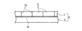
連続シートのラベル印刷用被記録媒体Sは、図3に示すように、裏面に粘着剤1aが塗布された粘着シート1が、台紙である剥離紙2上に重ね合わされた2枚構造となっており、画像形成部20によって粘着シート1の表面に画像が印刷された後、剥離紙2から剥がされて使用される。
As shown in FIG. 3, the recording medium S for label printing of continuous sheets has a two-sheet structure in which an
搬送部10は、搬送モータ18(図示せず)により回転駆動される供給ロール16及び製品巻取りロール19を備え、ロール状に巻き取られた連続シートのラベル印刷用被記録媒体Sを供給ロール16から繰り出して画像形成エリア80、平滑化エリア81、搬送バッファエリア82、およびラベル抜きエリア83へと順次搬送する。
The
供給ロール16及び製品巻取りロール19を駆動する搬送モータは、搬送モータ制御部(図示せず)に接続されて回転速度が制御されており、被記録媒体Sの搬送速度が制御される。例えば、画像形成エリア80、および平滑化エリア81における被記録媒体Sは、連続した一定の速度で搬送される。一方、ラベル抜きエリア83における被記録媒体Sは、ダイカッタ60の動きに連動して間欠的に搬送される。
The conveyance motor that drives the
平滑化エリア81とラベル抜きエリア83との間に設けられた搬送バッファエリア82は、平滑化エリア81とラベル抜きエリア83との搬送速度の差によって生じる連続シートのラベル印刷用被記録媒体Sの弛みを吸収するようになっている。
A
図2に示すように、画像形成エリア80に配置された画像形成部20は、各色のインクを吐出するインクジェットヘッド(インクジェット型ヘッドユニット)21Y、21M、21C、21Bを備え、そのインク吐出部先端が搬送される被記録媒体Sに向けて配置されている。このインクジェットヘッド21Y、21M、21C、21Bは、被記録媒体Sの幅方向長さをアレーとするフルライン型のヘッドであり、ピエゾ型のヘッドを採用している。インクジェットヘッド21Y、21M、21C、21Bには、ヘッド駆動制御部(図示せず)が接続されて、インク各色の吐出量が制御される。
As shown in FIG. 2, the
また、各インクジェットヘッド21Y、21M、21C、21Bの下流側には、活性エネルギー照射光源としての紫外線照射部22がそれぞれ配置され、インクが被記録媒体Sに乗った直後に硬化するだけの強力なエネルギーを与えて硬化させる。紫外線照射部22の配置は、被記録媒体Sに乗ったインクへのみ照射されるように構成され、インクジェットヘッド21Y、21M、21C、21Bのインク吐出口には照射されない構成とすることで、吐出口でのインク硬化を防止する。また、紫外線照射部22近傍の各部には、光反射防止の処置(例えば、つや消しの黒色処理)を施すのが好ましい。
Further, an
平滑化エリア81(画像形成部20の下流側)に配置された印刷表面平滑化装置30のニスコーター40は、被記録媒体Sを挟持しながら回転する一対の塗布ローラ41の表面に付着させた活性エネルギー硬化型透明インクを、被記録媒体Sの印刷された表面に供給して塗布する。活性エネルギー硬化型透明インクの塗布量は、被記録媒体S表面の凹凸を活性エネルギー硬化型透明インクで平滑にするのに必要な量とされる。
The
塗布される活性エネルギー硬化型透明インクは、紫外線照射により硬化可能なインクであり、主成分として、少なくとも重合性化合物と光開始剤を含む、例えば、カチオン重合系インク組成物、ラジカル重合系インク組成物、水性インク組成物などである。 The applied active energy curable transparent ink is an ink that can be cured by ultraviolet irradiation, and includes at least a polymerizable compound and a photoinitiator as main components. For example, a cationic polymerization ink composition, a radical polymerization ink composition Products, water-based ink compositions, and the like.
活性エネルギー硬化型透明インク平滑化手段50は、供給ロール51から供給された連続シート55が、搬送される被記録媒体Sの表面と平行に配置された一対のローラ53、54に巻き掛けられた後、巻き取りロール52に巻き取られるように帳架されている。即ち、連続シート55は、一対のローラ53、54の間で被記録媒体Sの表面と平行、且つ殆ど接触する程度に近接して配置される。
In the active energy curable transparent ink smoothing means 50, the
連続シート55の少なくとも被記録媒体S側の表面は、高い撥水性能を有しており、塗布された活性エネルギー硬化型透明インクに接して活性エネルギー硬化型透明インクを平滑化する平滑平面55aを形成する。連続シート55は、例えば、PET(ポリエチレンテレフタレート)フィルムであり、その表面はフッ素処理加工されて高い撥水性が付与されている。
At least the surface of the
連続シート55の撥水性は、低過ぎても、また高過ぎても活性エネルギー硬化型透明インクの表面平滑化に悪影響を与えるので、例えば、水活性エネルギー硬化型透明インクに対する静的接触角が20°〜140°程度の適度な撥水性を有することが望ましい。前記接触角が低すぎる場合には、連続シートからの活性エネルギー硬化型透明インクの剥離性が悪化し、無理に剥離すると表面性が劣化する。一方、前記接触角が高すぎる場合には、連続シート表面に活性エネルギー硬化型透明インクがはじかれる事によりインクがレヘ゛リンク゛しにくく、表面性が悪化する。
Even if the water repellency of the
活性エネルギー硬化型透明インク平滑化手段50の下流側には、活性エネルギー照射光源としての紫外線照射部56が配置され、活性エネルギー硬化型透明インク平滑化手段50により表面が平滑化された活性エネルギー硬化型透明インクに紫外線を照射して硬化させる。紫外線照射部56としては、例えば、メタルハライドランプ、高圧水銀ランプ、UV―LEDなどを用いることができる。
On the downstream side of the active energy curable transparent ink smoothing means 50, an
ダイカッタ60は、印刷された連続シートのラベル印刷用被記録媒体Sの粘着シート1にのみ、所望のラベル形状の切れ目1bを入れるものであり(図3参照)、シリンダカッタ61と、被記録媒体Sに対してシリンダカッタ61の反対側に配置された受けローラ62とを備える。シリンダカッタ61は、ラベル形状に形成された複数の切抜き刃61aがシリンダ61bの円筒面上に巻き付けられている。
The
ダイカッタ60は、シリンダカッタ61と受けローラ62とで被記録媒体Sを挟持しながら、被記録媒体Sの搬送速度に同期した速度で間欠的に揺動回転することにより、切抜き刃61aが被記録媒体Sの粘着シート1にのみラベル形状の切れ目1bを入れる。
The
ここで、ダイカッタ60が間欠的に揺動回転するのは、シリンダ61bの円筒面の円周方向長さと、必要とされる切抜き刃61aの長さとの不一致により生じる問題を解消するためである。即ち、ダイカッタ60を連続回転させてラベル形状の切れ目1bを入れると、シリンダカッタ61の切抜き刃61aがない部分に対応する被記録媒体Sも空送りされて、被記録媒体Sが無駄になる。ダイカッタ60を揺動回転させることにより、切れ目1bを連続して形成させることができ、被記録媒体Sの無駄をなくすことができる。
Here, the reason why the
カス取り部70は、ラベル(製品)Lとならない粘着シート1の不要部分(ラベルLの周辺部)を、剥離紙2から剥離させて巻き取り、廃棄する。製品であるラベルLは、剥離紙2に貼付された状態で剥離紙2と共に製品巻取りローラ19に巻き取られて製品とされる。
The
次に、紫外線硬化型インクジェットヘッドラベル印刷機100の作用について説明する。図1に示すように、ロール状に巻き取られた供給ロール16から繰り出された連続シートのラベル印刷用被記録媒体Sは、複数の搬送ローラ対11、12により画像形成エリア80へ搬送される。
Next, the operation of the ultraviolet curable inkjet
インクジェットヘッド21Y、21M、21C、21Bは、ヘッド駆動制御部(図示せず)に制御されて、被記録媒体Sの搬送速度に合わせたタイミングで、インク吐出部から紫外線硬化型インクを被記録媒体Sに向けて吐出する。被記録媒体Sに付着したインクには、直ちに紫外線照射部22から紫外線が照射されて硬化され、これにより印刷される。
The inkjet heads 21Y, 21M, 21C, and 21B are controlled by a head drive control unit (not shown) and receive UV curable ink from the ink discharge unit at a timing that matches the transport speed of the recording medium S. Discharge toward S. The ink adhering to the recording medium S is immediately irradiated with ultraviolet rays from the
図4に示すように、被記録媒体Sの印刷部は、硬化した複数色のインク3が重なり合って盛り上り、立体的になっている。インクの盛上り高さは、被記録媒体Sのインク吸収性によっても異なるが(吸収性が低いほど、また下地インクに対するインクの接触角が高いほど、高くなる)、一色あたり略10μm程度であり、4色のインクが使用された場合には、略40μmとなる状況も生まれる。
As shown in FIG. 4, the printing portion of the recording medium S is three-dimensionally swelled by overlapping the cured
印刷された被記録媒体Sは、平滑化エリア81に搬送され、先ず、ニスコーター40により、盛り上がったインク3全体を覆うように活性エネルギー硬化型透明インク4が印刷表面に塗布される(図4参照)。活性エネルギー硬化型透明インク4の塗布量は、インク3の盛上り高さによっても異なるが、被記録媒体S表面の凹凸を活性エネルギー硬化型透明インク4で平滑にするのに必要な量であり、多めであることが望ましい例えば5〜50μm程度である。
The printed recording medium S is conveyed to the smoothing
活性エネルギー硬化型透明インク4が塗布された被記録媒体Sは、活性エネルギー硬化型透明インク平滑化手段50によって活性エネルギー硬化型透明インク4が平滑化されることにより表面が平滑とされる。即ち、撥水性を有する連続シート55が、インク3を覆うように塗布された活性エネルギー硬化型透明インク4に接触し、活性エネルギー硬化型透明インク4を被記録媒体Sとの間に挟み込んで活性エネルギー硬化型透明インク4の表面を平滑にする。
The recording medium S coated with the active energy curable transparent ink 4 is smoothed by the active energy curable transparent ink 4 being smoothed by the active energy curable transparent ink smoothing means 50. That is, the
連続シート55は、被記録媒体Sの搬送速度と同期した速度で送ってもよく、停止させておいてもよい。連続シート55は、撥水性を有するので、活性エネルギー硬化型透明インク4の平滑化された部分(表面)が連続シート55から離れるとき、活性エネルギー硬化型透明インク4の平滑度に影響を与えることは殆どない。また、連続シート55に活性エネルギー硬化型透明インク4が付着して汚れることもない。
The
活性エネルギー硬化型透明インク平滑化手段50により表面が平滑化された活性エネルギー硬化型透明インク4は、紫外線照射部56から直ちに紫外線が照射されて硬化する。
The active energy curable transparent ink 4 whose surface is smoothed by the active energy curable transparent ink smoothing means 50 is immediately irradiated with ultraviolet rays from the
このようにして表面が平滑化された被記録媒体Sは、更に、搬送バッファエリア82を経由してラベル抜きエリア83に搬送され、ダイカッタ60によって粘着シート1にのみラベルLの形状に切れ目1bが入れられる。
The recording medium S whose surface is smoothed in this way is further conveyed to the
このとき、ダイカッタ60は、前述したように、間欠的に揺動しながらラベルLの形状の切れ目1bを入れるので、切れ目1bを連続して形成することができ、被記録媒体Sに無駄になる部分が発生することはない。
At this time, as described above, since the
そして、粘着シート1のラベルL以外の不要部分は、剥離紙2から剥離されてカス取り部70によって巻き取られる。一方、ラベルLは、剥離紙2上に貼付された状態で剥離紙2と共に製品巻取り部19に巻き取られて製品となる。
Unnecessary portions other than the label L of the pressure-
本実施形態の印刷表面平滑化装置30によれば、紫外線硬化型インク3などの活性エネルギー硬化型インクにより表面に凹凸のある画像が形成された被記録媒体Sの表面を、表面平滑な活性エネルギー硬化型透明インク4で覆って平滑化することができる。これにより、光沢感のある高画質の画像が得られる。
According to the printing
また、ニスコーター40から供給された活性エネルギー硬化型透明インク4の表面に、平滑な撥水性表面55aを接触させて活性エネルギー硬化型透明インク4を平滑に広げると共に、撥水性表面に沿って活性エネルギー硬化型透明インクが濡れ広がるので、活性エネルギー硬化型透明インク4が自然にレベリングして表面の凹凸が消去するまで待つこともなく、短時間で平滑化することができる。これにより、生産性の向上を図ることができる。
Further, the surface of the active energy curable transparent ink 4 supplied from the
更に、簡単且つ安価な機構のニスコーター40により、凹凸のある画像が形成された被記録媒体Sの表面に活性エネルギー硬化型透明インク4を安定して塗布することができる。
Furthermore, the active energy curable transparent ink 4 can be stably applied to the surface of the recording medium S on which the uneven image is formed by the
また、供給ロール51と巻き取りロール52の間に張架した連続シート55により平滑平面55aを形成しているので、連続使用などにより連続シート55の撥水性が低下した場合でも、新しい連続シート55を順次、供給ロール51から繰り出して交換し、常に平滑化性能の優れた連続シート55を用いて被記録媒体Sの表面を安定して平滑化することができる。
Further, since the smooth
更に、透明インクが活性エネルギー硬化型透明インクであり、活性エネルギー照射光源56が活性エネルギー硬化型透明インク平滑化手段50の位置又は下流に備えられるようにしたので、活性エネルギー硬化型透明インク4を平滑化しながら、または平滑化した直後に、活性エネルギー照射光源56から活性エネルギーを照射して硬化させることができ、これにより、平滑性の優れた平滑面が得られる。
Further, since the transparent ink is an active energy curable transparent ink and the active energy
尚、搬送バッファエリア82は、図5に示す活性エネルギー硬化型インクジェットヘッドラベル印刷機101のように、画像形成部20と印刷表面平滑化装置30との間に配置してもよいが、印刷表面平滑化装置30の下流側に配置すれば(図1参照)、被記録媒体Sを印刷表面平滑化装置30においても連続搬送することができる。尚、上記した搬送バッファエリア82の配置位置の関係は、以下の各実施形態においても同様である。
(第2実施形態)
The
(Second Embodiment)
次に、印刷表面平滑化装置の第2実施形態を図6に基づいて説明する。図6は本発明の第2実施形態である印刷表面平滑化装置が適用された活性エネルギー硬化型インクジェットヘッドラベル印刷機の概略構成図である。 Next, a second embodiment of the printing surface smoothing apparatus will be described with reference to FIG. FIG. 6 is a schematic configuration diagram of an active energy curable inkjet head label printer to which a printing surface smoothing apparatus according to a second embodiment of the present invention is applied.
尚、本実施形態の活性エネルギー硬化型インクジェットヘッドラベル印刷機200は、印刷表面平滑化装置130の構成が第1実施形態の紫外線硬化型インクジェットヘッドラベル印刷機100と異なる。その他の部分については、第1実施形態の紫外線硬化型インクジェットヘッドラベル印刷機100と同様であるので、同一部分には同一符号又は相当符号を付して説明を流用する。
The active energy curable inkjet
図6に示すように、第2実施形態の印刷表面平滑化装置130が適用された紫外線硬化型インクジェットヘッドラベル印刷機200の印刷表面平滑化装置130は、被記録媒体S表面に活性エネルギー硬化型透明インク4を供給するカバーインク供給手段としてインクジェットノズル140が用いられている。また、紫外線照射部56は、活性エネルギー硬化型透明インク平滑化手段50の一対のローラ53、54に架け渡された連続シート55上方に配置されている。連続シート55は、紫外線を透過可能な光透過シートであり、少なくとも被記録媒体S側の面は撥水性能を有する。
As shown in FIG. 6, the printing
画像形成部20で画像が形成された被記録媒体Sは、インクジェットノズル140から活性エネルギー硬化型透明インク4が吐出されて紫外線硬化型インクが硬化して形成された凹凸が覆われる。そして、被記録媒体Sが活性エネルギー硬化型透明インク平滑化手段50に達すると、活性エネルギー硬化型透明インク4は、被記録媒体Sと連続シート55とで挟持されて活性エネルギー硬化型透明インク4が平滑化される。ここで、連続シート55は紫外線を透過するので、これを介して、被記録媒体Sと連続シート55とで挟持されている活性エネルギー硬化型透明インク4に紫外線が照射され、活性エネルギー硬化型透明インク4が硬化する。
The recording medium S on which an image is formed by the
この場合、活性エネルギー硬化型透明インク4は、被記録媒体Sと連続シート55とで挟持されて空気中の酸素と遮断された状態で硬化するので、活性エネルギー硬化型透明インク4が大気中の酸素により重合阻害を起こし易いラジカル系インクであっても、重合阻害を抑制することができ、光強度の弱い安価な光源を使用することが可能なる。
In this case, since the active energy curable transparent ink 4 is sandwiched between the recording medium S and the
本実施形態の印刷表面平滑化装置130によれば、カバーインク供給手段がインクジェット140であるので、活性エネルギー硬化型透明インク4の供給量を制御しながら凹凸のある画像が形成された被記録媒体Sの表面に活性エネルギー硬化型透明インク4を供給することができる。これにより、少ない量の活性エネルギー硬化型透明インク4で表面が平滑で光沢感の均一な高画質の画像が得られる。
According to the printing
また、連続シート55が光透過シートであるので、活性エネルギー硬化型透明インク4の表面に連続シート55を接触させて活性エネルギー硬化型透明インク4を平滑に広げた状態で、連続シート55を介して活性エネルギーを照射し、硬化させることができる。これにより、活性エネルギー硬化型透明インク4と空気との接触を遮断した状態で硬化させることができるので、活性エネルギー硬化型透明インク4が、大気中の酸素により重合阻害を起こすラジカル系インクであっても、重合阻害を抑制することができ、光強度の弱い、安価な光源56の使用が可能なる。
Further, since the
その他の構成および作用は、第1実施形態の活性エネルギー硬化型インクジェットヘッドラベル印刷機と同様であるので、説明を流用する。
(第3実施形態)
Other configurations and operations are the same as those of the active energy curable inkjet head label printing machine according to the first embodiment, and the description will be used.
(Third embodiment)
次に、第3実施形態の印刷表面平滑化装置について図7に基づいて説明する。図7は第1および第2実施形態の平滑化エリア81とラベル抜きエリア83とが後処理装置として一体化されて独立し、画像形成エリア80と別個に設けられた活性エネルギー硬化型インクジェットヘッドラベル印刷装置の概略構成図である。
Next, the printing surface smoothing apparatus of 3rd Embodiment is demonstrated based on FIG. FIG. 7 shows an active energy curable ink jet head label in which the smoothing
図7に示すように、印刷表面平滑化装置150、ダイカッタ60、カス取り部70、および製品巻取り部19を含んで構成された後処理装置151は、画像形成部20から独立した装置として構成されている。また、印刷表面平滑化装置150は、第1実施形態において既に説明したニスコーター40と、第2実施形態において既に説明した活性エネルギー硬化型透明インク平滑化手段50および紫外線照射部56を備える。
As shown in FIG. 7, the
それ以外は、第2実施形態のデジタルラベル印刷装置200と同様であるので、同一部分には同一符号又は相当符号を付して説明を流用する。
Other than that, since it is the same as the digital
活性エネルギー硬化型インクジェットヘッドラベル印刷装置300は、先ず、画像形成部20のインクジェットヘッド21Y、21M、21C、21Bのインク吐出部から紫外線硬化型インクが被記録媒体Sに向けて吐出され、紫外線照射部22から紫外線が照射されて印刷される。
In the active energy curable inkjet head
印刷された被記録媒体Sは、後処理装置151に移され、ニスコーター40により活性エネルギー硬化型透明インク4が塗布され、更に活性エネルギー硬化型透明インク平滑化手段50によって活性エネルギー硬化型透明インク4が平滑化されると共に、紫外線照射部56から紫外線が照射されて硬化する。そして、ダイカッタ60によって粘着シート1にのみラベルLの形状に切れ目1bが入れられ(図3参照)、粘着シート1の不要部分が剥離紙2から剥離されてカス取り部70によって巻き取られる。一方、ラベルLは、剥離紙2上に貼付された状態で剥離紙2と共に製品巻取り部19に巻き取られて製品となる。
The printed recording medium S is transferred to the
本実施形態のデジタルラベル印刷装置300によれば、画像形成部20と後処理装置151とが、夫々独立した別個の装置として構成されているので、ラベルLの印刷工程と、印刷面の平滑化処理およびカス取りなどの後工程とを別作業として行うことができ、多種類のラベルLの後工程を纏めて行うことができる。
According to the digital
また、一般的に、印刷に要する時間は、カス取りなどの後処理に要する時間よりも遅い場合が多く、1台の後処理装置151で複数台の画像形成部20に対応することができ、効率的な処理が可能となる。
In general, the time required for printing is often slower than the time required for post-processing such as scrap removal, and a
その他の構成および作用は、第2実施形態の活性エネルギー硬化型インクジェットヘッドラベル印刷機と同様であるので、説明を流用する。
(第4実施形態)
Since other configurations and operations are the same as those of the active energy curable inkjet head label printer of the second embodiment, the description is diverted.
(Fourth embodiment)
次に、印刷表面平滑化装置の第4実施形態を図8に基づいて説明する。図8は本発明の第4実施形態である印刷表面平滑化装置が適用された活性エネルギー硬化型インクジェットヘッドラベル印刷機の概略構成図である。 Next, a fourth embodiment of the printing surface smoothing apparatus will be described with reference to FIG. FIG. 8 is a schematic configuration diagram of an active energy curable inkjet head label printer to which a printing surface smoothing apparatus according to a fourth embodiment of the present invention is applied.
尚、本実施形態の活性エネルギー硬化型インクジェットヘッドラベル印刷機400は、印刷表面平滑化装置180の構成が第1実施形態の紫外線硬化型インクジェットヘッドラベル印刷機100と異なる。その他の部分については、第1実施形態の紫外線硬化型インクジェットヘッドラベル印刷機100と同様であるので、同一部分には同一符号又は相当符号を付して説明を流用する。
The active energy curable inkjet
図8に示すように、紫外線硬化型インクジェットヘッドラベル印刷機400に適用された第4実施形態の印刷表面平滑化装置180は、被記録媒体S表面に活性エネルギー硬化型透明インク4を供給するカバーインク供給手段としてニスコーター40が用いられている。また、活性エネルギー硬化型透明インク平滑化手段180として、被記録媒体Sと平行に配設された2つのローラ153、154間にループ状に帳架されたベルト155により平滑平面155aを形成している。ベルト155は、紫外線を透過可能なベルトであり、少なくとも被記録媒体S側の面は撥水性能を有する。
As shown in FIG. 8, the printing
紫外線照射部56は、ループ状のベルト155の内側に配置されており、ベルト155を介して、被記録媒体Sとベルト155(平滑平面155a)とで挟持されている活性エネルギー硬化型透明インク4に紫外線を照射して、活性エネルギー硬化型透明インク4を硬化する。
The
上記のように構成された紫外線硬化型インクジェットヘッドラベル印刷機400においては、画像形成部20で画像が形成された被記録媒体Sは、ニスコーター40により活性エネルギー硬化型透明インク4が塗布された後、被記録媒体Sとベルト155とで挟持されて活性エネルギー硬化型透明インク4が平滑化される。
In the ultraviolet curable ink jet
平滑化された活性エネルギー硬化型透明インク4は、被記録媒体Sとベルト155とで挟持されて空気中の酸素と遮断された状態で、紫外線照射部56から光透過性のベルト155を介して活性エネルギー硬化型透明インク4に紫外線が照射されて硬化する。従って、活性エネルギー硬化型透明インク4が、大気中の酸素により重合阻害を起こし易いラジカル系インクであっても、重合阻害を抑制することができる。
The smoothed active energy curable transparent ink 4 is sandwiched between the recording medium S and the
本実施形態の印刷表面平滑化装置180によれば、活性エネルギー硬化型透明インク平滑化手段180が、少なくとも2つのローラ153、154間に帳架されるベルト155により平滑平面155aを形成するようにしたので、簡単な機構により広い平滑平面155aを構成することができる。
According to the printing
また、ベルト155が光透過ベルトであるので、活性エネルギー硬化型活性エネルギー硬化型透明インク4の表面に接触しているベルト155の上から、活性エネルギーを照射して硬化させることができる。これにより、活性エネルギー硬化型透明インク4と空気との接触を遮断した状態で硬化させることができ、活性エネルギー硬化型活性エネルギー硬化型透明インク4が、大気中の酸素により重合阻害を起こすラジカル系インクであっても、重合阻害を抑制して、光強度の弱い、安価な光源56の使用が可能なる。
Further, since the
その他の構成および作用は、第1実施形態の活性エネルギー硬化型インクジェットヘッドラベル印刷機と同様であるので、説明を流用する。
(第5実施形態)
Other configurations and operations are the same as those of the active energy curable inkjet head label printing machine according to the first embodiment, and the description will be used.
(Fifth embodiment)
次に、印刷表面平滑化装置の第5実施形態を図9に基づいて説明する。図9は本発明の第5実施形態である印刷表面平滑化装置が適用された活性エネルギー硬化型インクジェットヘッドラベル印刷機の概略構成図である。 Next, a fifth embodiment of the printing surface smoothing apparatus will be described with reference to FIG. FIG. 9 is a schematic configuration diagram of an active energy curable inkjet head label printer to which a printing surface smoothing apparatus according to a fifth embodiment of the present invention is applied.
尚、本実施形態の活性エネルギー硬化型インクジェットヘッドラベル印刷機500は、印刷表面平滑化装置の構成が第1実施形態の紫外線硬化型インクジェットヘッドラベル印刷機100と異なる。その他の部分については、第1実施形態の紫外線硬化型インクジェットヘッドラベル印刷機100と同様であるので、同一部分には同一符号又は相当符号を付して説明を簡略化又は省略する。
The active energy curable inkjet
図9に示すように、紫外線硬化型インクジェットヘッドラベル印刷機500に適用された第5実施形態の印刷表面平滑化装置170は、被記録媒体S表面に活性エネルギー硬化型透明インク4を供給するカバーインク供給手段としてニスコーター40が用いられている。また、活性エネルギー硬化型透明インク平滑化手段として、ドラム171が用いられており、被記録媒体Sの表面(印刷面)に接触するドラム171の軸線155aが平滑線を形成して塗布された活性エネルギー硬化型透明インク4を平滑化する。ドラム171の表面171bは、撥水性能を有する。
As shown in FIG. 9, the printing
紫外線照射部56は、ドラム171の下流側に配置されており、ドラム171によって平滑化された活性エネルギー硬化型透明インク4に紫外線を照射して硬化させる。
The
上記のように構成された紫外線硬化型インクジェットヘッドラベル印刷機500においては、画像形成部20で画像が形成された被記録媒体Sは、ニスコーター40により活性エネルギー硬化型透明インク4が塗布された後、被記録媒体Sがドラム171と接触して軸線155aにより活性エネルギー硬化型透明インク4が平滑化される。そして、紫外線照射部56から照射される紫外線により硬化する。またドラム171を光透過性ドラムとしてドラム内部に活性エネルギー照射部を配置し、活性エネルギー硬化型活性エネルギー硬化型透明インク4の表面に接触しているドラム171の内面から、活性エネルギーを照射して硬化させることができる。これにより、活性エネルギー硬化型透明インク4と空気との接触を遮断した状態で硬化させることができ、活性エネルギー硬化型活性エネルギー硬化型透明インク4が、大気中の酸素により重合阻害を起こすラジカル系インクであっても、重合阻害を抑制して、光強度の弱い、安価な光源の使用が可能なる。
In the ultraviolet curable inkjet
本実施形態の印刷表面平滑化装置170によれば、活性エネルギー硬化型透明インク平滑化手段が、ドラム171表面の軸線155aにより平滑線を形成するので、活性エネルギー硬化型透明インク平滑化手段を簡素化することができる。
According to the printing
その他の構成および作用は、第1実施形態の活性エネルギー硬化型インクジェットヘッドラベル印刷機100と同様であるので、説明を流用する。
Since other configurations and operations are the same as those of the active energy curable inkjet
尚、本発明は、前述した各実施形態および変形例に限定されるものではなく、適宜、変形、改良、等が可能である。 In addition, this invention is not limited to each embodiment and modification which were mentioned above, A deformation | transformation, improvement, etc. are possible suitably.
また、本発明においては、印刷表面平滑化装置を紫外線硬化型インクジェットヘッドラベル印刷機に適用したものとして説明したが、これに限定されるものではなく、後処理として活性エネルギー硬化型透明インクを塗布する任意の形式の印刷機に適用することができ、同様の効果を奏する。 In the present invention, the printing surface smoothing device has been described as being applied to an ultraviolet curable ink jet head label printer. However, the present invention is not limited to this, and an active energy curable transparent ink is applied as a post-treatment. The present invention can be applied to any type of printing press and has the same effect.
ここで、本発明で言う「活性エネルギー」とは、その照射によりインク組成物中において開始種を発生させうるエネルギーを付与することができるものであれば、特に制限はなく、広く、α線、γ線、X線、紫外線、可視光線、電子線などを包含するものである。中でも、硬化感度及び装置の入手容易性の観点からは、紫外線及び電子線が好ましく、特に紫外線が好ましい。従って、本発明のインク組成物としては、紫外線を照射することにより硬化可能なインク組成物であることが好ましい。 Here, the “active energy” referred to in the present invention is not particularly limited as long as it can impart energy capable of generating a starting species in the ink composition by the irradiation, and broadly includes α rays, Including gamma rays, X-rays, ultraviolet rays, visible rays, electron beams, and the like. Among these, from the viewpoints of curing sensitivity and device availability, ultraviolet rays and electron beams are preferable, and ultraviolet rays are particularly preferable. Therefore, the ink composition of the present invention is preferably an ink composition that can be cured by irradiation with ultraviolet rays.
本発明のインクジェット記録装置において、活性エネルギーのピーク波長は、インク組成物中の増感色素の吸収特性にもよるが、例えば、200〜600nm、好ましくは、300〜450nm、より好ましくは、350〜450nmであることが適当である。また、本発明のインク組成物の(a)電子移動型開始系は、低出力の活性エネルギーであっても十分な感度を有するものである。従って、活性エネルギーの出力は、例えば、2,000mJ/cm2以下、好ましくは、10〜2,000mJ/cm2、より好ましくは、20〜1,000mJ/cm2、更に好ましくは、50〜800mJ/cm2の照射エネルギーであることが適当である。また、活性エネルギーは、露光面照度(被記録媒体表面の最高照度)が、例えば、10〜2,000mW/cm2、好ましくは、20〜1,000mW/cm2で照射されることが適当である。
特に、本発明のインクジェット記録装置では、活性エネルギー照射が、発光波長ピークが390〜420nmであり、かつ、前記被記録媒体表面での最高照度が10〜1,000mW/cm2となる紫外線を発生する発光ダイオードから照射されることが好ましい。
In the inkjet recording apparatus of the present invention, the peak wavelength of the active energy depends on the absorption characteristics of the sensitizing dye in the ink composition, but is, for example, 200 to 600 nm, preferably 300 to 450 nm, and more preferably 350 to It is suitable that it is 450 nm. In addition, the (a) electron transfer type initiation system of the ink composition of the present invention has sufficient sensitivity even with low output active energy. Therefore, the output of active energy is, for example, 2,000 mJ / cm 2 or less, preferably 10 to 2,000 mJ / cm 2 , more preferably 20 to 1,000 mJ / cm 2 , and still more preferably 50 to 800 mJ. An irradiation energy of / cm 2 is appropriate. The active energy exposure surface illuminance (the maximum illuminance of the surface of the recording medium) is, for example, 10 to 2,000 mW / cm 2, preferably, suitably be irradiated at 20 to 1,000 mW / cm 2 is there.
In particular, in the ink jet recording apparatus of the present invention, irradiation with active energy generates ultraviolet rays having an emission wavelength peak of 390 to 420 nm and a maximum illuminance of 10 to 1,000 mW / cm 2 on the surface of the recording medium. The light emitting diode is preferably irradiated.
また、本発明のインクジェット記録装置では、活性エネルギーは被記録媒体上に吐出されたインク組成物に対して、例えば、0.01〜120秒、好ましくは0.1〜90秒照射することが適当である。
更に、本発明のインクジェット記録装置では、インク組成物を一定温度に加温するとともに、インク組成物の被記録媒体への着弾から活性エネルギーの照射までの時間を、0.01〜0.5秒とすることが望ましく、好ましくは0.02〜0.3秒、更に好ましくは0.03〜0.15秒である。このようにインク組成物の被記録媒体への着弾から活性エネルギーの照射までの時間を極短時間に制御することにより、着弾したインク組成物が硬化前に滲むことを防止することが可能となる。
In the ink jet recording apparatus of the present invention, it is appropriate that the active energy is applied to the ink composition ejected on the recording medium, for example, 0.01 to 120 seconds, preferably 0.1 to 90 seconds. It is.
Furthermore, in the ink jet recording apparatus of the present invention, the ink composition is heated to a constant temperature, and the time from the landing of the ink composition on the recording medium to the irradiation of the active energy is 0.01 to 0.5 seconds. Preferably, it is 0.02 to 0.3 seconds, and more preferably 0.03 to 0.15 seconds. Thus, by controlling the time from the landing of the ink composition to the recording medium to the irradiation of the active energy to an extremely short time, it is possible to prevent the landed ink composition from bleeding before curing. .
なお、本発明のインクジェット記録装置を用いてカラー画像を得るためには、明度の低い色から順に重ねていくことが好ましい。このように重ねることにより、下部のインクまで活性エネルギーが到達しやすくなり、良好な硬化感度、残留モノマーの低減、臭気の低減、密着性の向上が期待できる。また、活性エネルギーの照射は、全色を射出してまとめて露光することが可能だが、1色毎に露光するほうが、硬化促進の観点で好ましい。 In order to obtain a color image using the ink jet recording apparatus of the present invention, it is preferable to superimpose in order from the color with the lowest brightness. By overlapping in this way, the active energy can easily reach the lower ink, and good curing sensitivity, reduction of residual monomers, reduction of odor, and improvement of adhesion can be expected. In addition, although irradiation with active energy can be performed by injecting all the colors and exposing them together, exposure for each color is preferable from the viewpoint of promoting curing.
また、上述したように、本発明のインク組成物のような活性エネルギー硬化型インクは、吐出されるインク組成物を一定温度にすることが望ましいことから、インク供給タンクからインクジェットヘッド部分までは、断熱及び加温による温度制御を行うことが好ましい。また、加熱するヘッドユニットは、装置本体を外気からの温度の影響を受けないよう、熱的に遮断若しくは断熱されていることが好ましい。加熱に要するプリンター立上げ時間を短縮するため、或いは熱エネルギーのロスを低減するために、他部位との断熱を行うとともに、加熱ユニット全体の熱容量を小さくすることが好ましい。 Further, as described above, since the active energy curable ink such as the ink composition of the present invention desirably has a constant temperature for the discharged ink composition, from the ink supply tank to the inkjet head portion, It is preferable to perform temperature control by heat insulation and heating. Moreover, it is preferable that the head unit to be heated is thermally shielded or insulated so that the apparatus main body is not affected by the temperature from the outside air. In order to shorten the printer start-up time required for heating or to reduce the loss of heat energy, it is preferable to insulate from other parts and reduce the heat capacity of the entire heating unit.
また、活性エネルギー源としては、水銀ランプやガス・固体レーザー等が主に利用されており、紫外線光硬化型インクジェットには、水銀ランプ、メタルハライドランプが広く知られている。更には、GaN系半導体紫外発光デバイスへの置き換えは産業的、環境的にも非常に有用である。更にLED(UV−LED),LD(UV−LD)は小型、高寿命、高効率、低コストであり、活性エネルギー硬化型インクジェット用放射源として期待されている。 Further, mercury lamps and gas / solid lasers are mainly used as active energy sources, and mercury lamps and metal halide lamps are widely known as ultraviolet light curable ink jets. Furthermore, replacement with a GaN-based semiconductor ultraviolet light emitting device is very useful industrially and environmentally. Furthermore, LED (UV-LED) and LD (UV-LD) are small, have a long lifetime, high efficiency, and low cost, and are expected as radiation sources for active energy curable ink jets.
また、上記のように、活性エネルギー源として、発光ダイオード(LED)及びレーザーダイオード(LD)を用いることが可能である。特に、紫外線源を要する場合、紫外LED及び紫外LDを使用することができる。例えば、日亜化学(株)は、主放出スペクトルが365nmと420nmとの間の波長を有する紫色LEDを上市している。更に、一層短い波長が必要とされる場合、米国特許番号第6,084,250号明細書は、300nmと370nmとの間に中心付けされた活性エネルギーを放出し得るLEDを開示している。また、他の紫外LEDも、入手可能であり、異なる紫外線帯域の放射を照射することができる。本発明で特に好ましい活性エネルギー源は、UV−LEDであり、特に好ましくは、350〜420nmにピーク波長を有するUV−LEDである。 Further, as described above, a light emitting diode (LED) and a laser diode (LD) can be used as the active energy source. In particular, when an ultraviolet light source is required, an ultraviolet LED and an ultraviolet LD can be used. For example, Nichia Corporation has introduced a purple LED whose main emission spectrum has a wavelength between 365 nm and 420 nm. Further, when shorter wavelengths are required, US Pat. No. 6,084,250 discloses an LED that can emit active energy centered between 300 nm and 370 nm. Other ultraviolet LEDs are also available and can emit radiation in different ultraviolet bands. A particularly preferable active energy source in the present invention is a UV-LED, and a UV-LED having a peak wavelength of 350 to 420 nm is particularly preferable.
〔被記録媒体〕
本発明のインク組成物を適用しうる被記録媒体としては、特に制限はなく、通常の非コート紙、コート紙などの紙類、いわゆる軟包装に用いられる各種非吸収性樹脂材料或いは、それをフィルム状に成形した樹脂フィルムを用いることができ、各種プラスチックフィルムとしては、例えば、PETフィルム、OPSフィルム、OPPフィルム、ONyフィルム、PVCフィルム、PEフィルム、TACフィルム等を挙げることができる。その他、被記録媒体材料として使用しうるプラスチックとしては、ポリカーボネート、アクリル樹脂、ABS、ポリアセタール、PVA、ゴム類などが挙げられる。また、金属類や、ガラス類も被記録媒体として使用可能である。
本発明のインク組成物において、硬化時の熱収縮が少ない材料を選択した場合、硬化したインク組成物と被記録媒体との密着性に優れるため、インクの硬化収縮、硬化反応時の発熱などにより、フィルムのカール、変形が生じやすいフィルム、例えば、熱でシュリンク可能な、PETフィルム、OPSフィルム、OPPフィルム、ONyフィルム、PVCフィルムなどにおいても、高精細な画像を形成しうるという利点を有する。
[Recording medium]
The recording medium to which the ink composition of the present invention can be applied is not particularly limited, and various kinds of non-absorbing resin materials used for ordinary non-coated paper, coated paper, so-called soft packaging, or the like. A resin film formed into a film can be used, and examples of the various plastic films include PET film, OPS film, OPP film, ONy film, PVC film, PE film, and TAC film. In addition, examples of the plastic that can be used as the recording medium material include polycarbonate, acrylic resin, ABS, polyacetal, PVA, and rubbers. Metals and glasses can also be used as the recording medium.
In the ink composition of the present invention, when a material with low thermal shrinkage at the time of curing is selected, the adhesive property between the cured ink composition and the recording medium is excellent. Films that tend to curl and deform, such as heat-shrinkable PET film, OPS film, OPP film, ONy film, PVC film, etc., have the advantage that a high-definition image can be formed.
以下に、本発明で使用できるインク組成物に用いられる各構成成分について順次説明する。
〔インク組成物〕
本発明に用いられるインク組成物は、活性エネルギーの照射により硬化可能なインク組成物であり、例えば、カチオン重合系インク組成物、ラジカル重合系インク組成物、水性インク組成物等が挙げられる。これら組成物について以下詳細に説明する。
Below, each component used for the ink composition which can be used by this invention is demonstrated sequentially.
[Ink composition]
The ink composition used in the present invention is an ink composition that can be cured by irradiation with active energy, and examples thereof include a cationic polymerization ink composition, a radical polymerization ink composition, and a water-based ink composition. These compositions will be described in detail below.
(カチオン重合系インク組成物)
カチオン重合系インク組成物は、(a)カチオン重合性化合物と、(b)活性エネルギーの照射により酸を発生する化合物、(c)着色剤を含有する。所望により、更に紫外線吸収剤、増感剤、酸化防止剤、褪色防止剤、導電性塩類、溶剤、高分子化合物、界面活性剤等を含有してもよい。
以下、カチオン重合系インク組成物に用いられる各構成成分について順次説明する。
(Cationically-polymerized ink composition)
The cationic polymerization-type ink composition contains (a) a cationic polymerizable compound, (b) a compound that generates an acid upon irradiation with active energy, and (c) a colorant. If desired, it may further contain an ultraviolet absorber, a sensitizer, an antioxidant, an antifading agent, a conductive salt, a solvent, a polymer compound, a surfactant and the like.
Hereafter, each component used for a cationic polymerization type ink composition is demonstrated one by one.
〔(a)カチオン重合性化合物〕
本発明に用いられる(a)カチオン重合性化合物は、後述する(b)活性エネルギーの照射により酸を発生する化合物から発生する酸により重合反応を生起し、硬化する化合物であれば特に制限はなく、光カチオン重合性モノマーとして知られる各種公知のカチオン重合性のモノマーを使用することができる。カチオン重合性モノマーとしては、例えば、特開平6−9714号、特開2001−31892、同2001−40068、同2001−55507、同2001−310938、同2001−310937、同2001−220526などの各公報に記載されている、エポキシ化合物、ビニルエーテル化合物、オキセタン化合物などが挙げられる。
[(A) Cationic polymerizable compound]
The (a) cationic polymerizable compound used in the present invention is not particularly limited as long as it is a compound that causes a polymerization reaction by an acid generated from a compound that generates an acid by irradiation of active energy (b) described later and cures. Various known cationic polymerizable monomers known as photo cationic polymerizable monomers can be used. Examples of the cationic polymerizable monomer include JP-A-6-9714, JP-A-2001-31892, JP-A-2001-40068, JP-A-2001-55507, JP-A-2001-310938, JP-A-2001-310937, and JP-A-2001-220526. Examples thereof include epoxy compounds, vinyl ether compounds, oxetane compounds and the like.
エポキシ化合物としては、芳香族エポキシド、脂環式エポキシド、脂肪族エポキシドなどが挙げられる。
芳香族エポキシドとしては、少なくとも1個の芳香族核を有する多価フェノール或いはそのアルキレンオキサイド付加体とエピクロルヒドリンとの反応によって製造されるジ又はポリグリシジルエーテルが挙げられ、例えば、ビスフェノールA或いはそのアルキレンオキサイド付加体のジ又はポリグリシジルエーテル、水素添加ビスフェノールA或いはそのアルキレンオキサイド付加体のジ又はポリグリシジルエーテル、並びにノボラック型エポキシ樹脂等が挙げられる。ここで、アルキレンオキサイドとしては、エチレンオキサイド及びプロピレンオキサイド等が挙げられる。
Examples of the epoxy compound include aromatic epoxides, alicyclic epoxides, and aliphatic epoxides.
Aromatic epoxides include di- or polyglycidyl ethers produced by the reaction of polyphenols having at least one aromatic nucleus or their alkylene oxide adducts and epichlorohydrin, such as bisphenol A or its alkylene oxides. Examples thereof include di- or polyglycidyl ethers of adducts, di- or polyglycidyl ethers of hydrogenated bisphenol A or alkylene oxide adducts thereof, and novolak type epoxy resins. Here, examples of the alkylene oxide include ethylene oxide and propylene oxide.
脂環式エポキシドとしては、少なくとも1個のシクロへキセン又はシクロペンテン環等のシクロアルカン環を有する化合物を、過酸化水素、過酸等の適当な酸化剤でエポキシ化することによって得られる、シクロヘキセンオキサイド又はシクロペンテンオキサイド含有化合物が好ましく挙げられる。 As the alicyclic epoxide, cyclohexene oxide obtained by epoxidizing a compound having at least one cycloalkane ring such as cyclohexene or cyclopentene ring with a suitable oxidizing agent such as hydrogen peroxide or peracid. Or a cyclopentene oxide containing compound is mentioned preferably.
脂肪族エポキシドとしては、脂肪族多価アルコール或いはそのアルキレンオキサイド付加体のジ又はポリグリシジルエーテル等が挙げられる。その代表例としては、エチレングリコールのジグリシジルエーテル、プロピレングリコールのジグリシジルエーテル又は1,6−ヘキサンジオールのジグリシジルエーテル等のアルキレングリコールのジグリシジルエーテル、グリセリン或いはそのアルキレンオキサイド付加体のジ又はトリグリシジルエーテル等の多価アルコールのポリグリシジルエーテル、ポリエチレングリコール或いはそのアルキレンオキサイド付加体のジグリシジルエーテル、ポリプロピレングリコール或いはそのアルキレンオキサイド付加体のジグリシジルエーテルに代表されるポリアルキレングリコールのジグリシジルエーテル等が挙げられる。ここで、アルキレンオキサイドとしては、エチレンオキサイド及びプロピレンオキサイド等が挙げられる。 Examples of the aliphatic epoxide include dihydric polyglycidyl ethers of aliphatic polyhydric alcohols or alkylene oxide adducts thereof. Typical examples include diglycidyl ether of ethylene glycol, diglycidyl ether of propylene glycol or diglycidyl ether of alkylene glycol such as diglycidyl ether of 1,6-hexanediol, di- or tri- or di- or tri-glycol or adducts thereof. Polyglycidyl ether of polyhydric alcohol such as glycidyl ether, diglycidyl ether of polyethylene glycol or alkylene oxide adduct thereof, diglycidyl ether of polyalkylene glycol represented by diglycidyl ether of polypropylene glycol or alkylene oxide adduct thereof, etc. Can be mentioned. Here, examples of the alkylene oxide include ethylene oxide and propylene oxide.
エポキシ化合物は、単官能であっても多官能であってもよい。
本発明に用いうる単官能エポキシ化合物の例としては、例えば、フェニルグリシジルエーテル、p−tert−ブチルフェニルグリシジルエーテル、ブチルグリシジルエーテル、2−エチルヘキシルグリシジルエーテル、アリルグリシジルエーテル、1,2−ブチレンオキサイド、1,3−ブタジエンモノオキサイド、1,2−エポキシドデカン、エピクロロヒドリン、1,2−エポキシデカン、スチレンオキサイド、シクロヘキセンオキサイド、3−メタクリロイルオキシメチルシクロヘキセンオキサイド、3−アクリロイルオキシメチルシクロヘキセンオキサイド、3−ビニルシクロヘキセンオキサイド等が挙げられる。
The epoxy compound may be monofunctional or polyfunctional.
Examples of monofunctional epoxy compounds that can be used in the present invention include, for example, phenyl glycidyl ether, p-tert-butylphenyl glycidyl ether, butyl glycidyl ether, 2-ethylhexyl glycidyl ether, allyl glycidyl ether, 1,2-butylene oxide, 1,3-butadiene monooxide, 1,2-epoxydodecane, epichlorohydrin, 1,2-epoxydecane, styrene oxide, cyclohexene oxide, 3-methacryloyloxymethylcyclohexene oxide, 3-acryloyloxymethylcyclohexene oxide, 3 -Vinylcyclohexene oxide etc. are mentioned.
また、多官能エポキシ化合物の例としては、例えば、ビスフェノールAジグリシジルエーテル、ビスフェノールFジグリシジルエーテル、ビスフェノールSジグリシジルエーテル、臭素化ビスフェノールAジグリシジルエーテル、臭素化ビスフェノールFジグリシジルエーテル、臭素化ビスフェノールSジグリシジルエーテル、エポキシノボラック樹脂、水添ビスフェノールAジグリシジルエーテル、水添ビスフェノールFジグリシジルエーテル、水添ビスフェノールSジグリシジルエーテル、3,4−エポキシシクロヘキシルメチル−3',4'−エポキシシクロヘキサンカルボキシレート、2−(3,4−エポキシシクロヘキシル−5,5−スピロ−3,4−エポキシ)シクロヘキサン−メタ−ジオキサン、ビス(3,4−エポキシシクロヘキシルメチル)アジペート、ビニルシクロヘキセンオキサイド、4−ビニルエポキシシクロヘキサン、ビス(3,4−エポキシ−6−メチルシクロヘキシルメチル)アジペート、3,4−エポキシ−6−メチルシクロヘキシル−3',4'−エポキシ−6'−メチルシクロヘキサンカルボキシレート、メチレンビス(3,4−エポキシシクロヘキサン)、ジシクロペンタジエンジエポキサイド、エチレングリコールのジ(3,4−エポキシシクロヘキシルメチル)エーテル、エチレンビス(3,4−エポキシシクロヘキサンカルボキシレート)、エポキシヘキサヒドロフタル酸ジオクチル、エポキシヘキサヒドロフタル酸ジ−2−エチルヘキシル、1,4−ブタンジオールジグリシジルエーテル、1,6−ヘキサンジオールジグリシジルエーテル、グリセリントリグリシジルエーテル、トリメチロールプロパントリグリシジルエーテル、ポリエチレングリコールジグリシジルエーテル、ポリプロピレングリコールジグリシジルエーテル類、1,1,3−テトラデカジエンジオキサイド、リモネンジオキサイド、1,2,7,8−ジエポキシオクタン、1,2,5,6−ジエポキシシクロオクタン等が挙げられる。 Examples of polyfunctional epoxy compounds include, for example, bisphenol A diglycidyl ether, bisphenol F diglycidyl ether, bisphenol S diglycidyl ether, brominated bisphenol A diglycidyl ether, brominated bisphenol F diglycidyl ether, and brominated bisphenol. S diglycidyl ether, epoxy novolac resin, hydrogenated bisphenol A diglycidyl ether, hydrogenated bisphenol F diglycidyl ether, hydrogenated bisphenol S diglycidyl ether, 3,4-epoxycyclohexylmethyl-3 ′, 4′-epoxycyclohexanecarboxy 2- (3,4-epoxycyclohexyl-5,5-spiro-3,4-epoxy) cyclohexane-meta-dioxane, bis (3,4-epoxycyclo) Xylmethyl) adipate, vinylcyclohexene oxide, 4-vinylepoxycyclohexane, bis (3,4-epoxy-6-methylcyclohexylmethyl) adipate, 3,4-epoxy-6-methylcyclohexyl-3 ′, 4′-epoxy-6 '-Methylcyclohexanecarboxylate, methylenebis (3,4-epoxycyclohexane), dicyclopentadiene diepoxide, ethylene glycol di (3,4-epoxycyclohexylmethyl) ether, ethylenebis (3,4-epoxycyclohexanecarboxylate) , Epoxyhexahydrophthalate dioctyl, epoxyhexahydrophthalate di-2-ethylhexyl, 1,4-butanediol diglycidyl ether, 1,6-hexanediol diglycidyl ether Glycerin triglycidyl ether, trimethylolpropane triglycidyl ether, polyethylene glycol diglycidyl ether, polypropylene glycol diglycidyl ethers, 1,1,3-tetradecadiene dioxide, limonene dioxide, 1,2,7,8- Examples include diepoxyoctane and 1,2,5,6-diepoxycyclooctane.
これらのエポキシ化合物の中でも、芳香族エポキシド及び脂環式エポキシドが、硬化速度に優れるという観点から好ましく、特に脂環式エポキシドが好ましい。 Among these epoxy compounds, aromatic epoxides and alicyclic epoxides are preferable from the viewpoint of excellent curing speed, and alicyclic epoxides are particularly preferable.
ビニルエーテル化合物としては、例えば、エチレングリコールジビニルエーテル、ジエチレングリコールジビニルエーテル、トリエチレングリコールジビニルエーテル、プロピレングリコールジビニルエーテル、ジプロピレングリコールジビニルエーテル、ブタンジオールジビニルエーテル、ヘキサンジオールジビニルエーテル、シクロヘキサンジメタノールジビニルエーテル、トリメチロールプロパントリビニルエーテル等のジ又はトリビニルエーテル化合物、エチルビニルエーテル、n−ブチルビニルエーテル、イソブチルビニルエーテル、オクタデシルビニルエーテル、シクロヘキシルビニルエーテル、ヒドロキシブチルビニルエーテル、2−エチルヘキシルビニルエーテル、シクロヘキサンジメタノールモノビニルエーテル、n−プロピルビニルエーテル、イソプロピルビニルエーテル、イソプロペニルエーテル−O−プロピレンカーボネート、ドデシルビニルエーテル、ジエチレングリコールモノビニルエーテル、オクタデシルビニルエーテル等のモノビニルエーテル化合物等が挙げられる。 Examples of the vinyl ether compound include ethylene glycol divinyl ether, diethylene glycol divinyl ether, triethylene glycol divinyl ether, propylene glycol divinyl ether, dipropylene glycol divinyl ether, butanediol divinyl ether, hexanediol divinyl ether, cyclohexanedimethanol divinyl ether, Di- or trivinyl ether compounds such as methylolpropane trivinyl ether, ethyl vinyl ether, n-butyl vinyl ether, isobutyl vinyl ether, octadecyl vinyl ether, cyclohexyl vinyl ether, hydroxybutyl vinyl ether, 2-ethylhexyl vinyl ether, cyclohexane dimethanol monovinyl ether, n-propyl Pills vinyl ether, isopropyl vinyl ether, isopropenyl ether -O- propylene carbonate, dodecyl vinyl ether, diethylene glycol monovinyl ether, and octadecyl vinyl ether.
ビニルエーテル化合物は、単官能であっても多官能であってもよい。
具体的には、単官能ビニルエーテルの例としては、例えば、メチルビニルエーテル、エチルビニルエーテル、プロピルビニルエーテル、n−ブチルビニルエーテル、t−ブチルビニルエーテル、2−エチルヘキシルビニルエーテル、n−ノニルビニルエーテル、ラウリルビニルエーテル、シクロヘキシルビニルエーテル、シクロヘキシルメチルビニルエーテル、4−メチルシクロヘキシルメチルビニルエーテル、ベンジルビニルエーテル、ジシクロペンテニルビニルエーテル、2−ジシクロペンテノキシエチルビニルエーテル、メトキシエチルビニルエーテル、エトキシエチルビニルエーテル、ブトキシエチルビニルエーテル、メトキシエトキシエチルビニルエーテル、エトキシエトキシエチルビニルエーテル、メトキシポリエチレングリコールビニルエーテル、テトラヒドロフリフリルビニルエーテル、2−ヒドロキシエチルビニルエーテル、2−ヒドロキシプロピルビニルエーテル、4−ヒドロキシブチルビニルエーテル、4−ヒドロキシメチルシクロヘキシルメチルビニルエーテル、ジエチレングリコールモノビニルエーテル、ポリエチレングリコールビニルエーテル、クロルエチルビニルエーテル、クロルブチルビニルエーテル、クロルエトキシエチルビニルエーテル、フェニルエチルビニルエーテル、フェノキシポリエチレングリコールビニルエーテル等が挙げられる。
The vinyl ether compound may be monofunctional or polyfunctional.
Specifically, examples of monofunctional vinyl ethers include, for example, methyl vinyl ether, ethyl vinyl ether, propyl vinyl ether, n-butyl vinyl ether, t-butyl vinyl ether, 2-ethylhexyl vinyl ether, n-nonyl vinyl ether, lauryl vinyl ether, cyclohexyl vinyl ether, Cyclohexylmethyl vinyl ether, 4-methylcyclohexyl methyl vinyl ether, benzyl vinyl ether, dicyclopentenyl vinyl ether, 2-dicyclopentenoxyethyl vinyl ether, methoxyethyl vinyl ether, ethoxyethyl vinyl ether, butoxyethyl vinyl ether, methoxyethoxyethyl vinyl ether, ethoxyethoxyethyl vinyl ether , Methoxypolyethyleneglycol Vinyl ether, tetrahydrofurfuryl vinyl ether, 2-hydroxyethyl vinyl ether, 2-hydroxypropyl vinyl ether, 4-hydroxybutyl vinyl ether, 4-hydroxymethylcyclohexyl methyl vinyl ether, diethylene glycol monovinyl ether, polyethylene glycol vinyl ether, chloroethyl vinyl ether, chlorobutyl vinyl ether, Examples thereof include chloroethoxyethyl vinyl ether, phenylethyl vinyl ether, phenoxypolyethylene glycol vinyl ether and the like.
また、多官能ビニルエーテルの例としては、例えば、エチレングリコールジビニルエーテル、ジエチレングリコールジビニルエーテル、ポリエチレングリコールジビニルエーテル、プロピレングリコールジビニルエーテル、ブチレングリコールジビニルエーテル、ヘキサンジオールジビニルエーテル、ビスフェノールAアルキレンオキサイドジビニルエーテル、ビスフェノールFアルキレンオキサイドジビニルエーテルなどのジビニルエーテル類;トリメチロールエタントリビニルエーテル、トリメチロールプロパントリビニルエーテル、ジトリメチロールプロパンテトラビニルエーテル、グリセリントリビニルエーテル、ペンタエリスリトールテトラビニルエーテル、ジペンタエリスリトールペンタビニルエーテル、ジペンタエリスリトールヘキサビニルエーテル、エチレンオキサイド付加トリメチロールプロパントリビニルエーテル、プロピレンオキサイド付加トリメチロールプロパントリビニルエーテル、エチレンオキサイド付加ジトリメチロールプロパンテトラビニルエーテル、プロピレンオキサイド付加ジトリメチロールプロパンテトラビニルエーテル、エチレンオキサイド付加ペンタエリスリトールテトラビニルエーテル、プロピレンオキサイド付加ペンタエリスリトールテトラビニルエーテル、エチレンオキサイド付加ジペンタエリスリトールヘキサビニルエーテル、プロピレンオキサイド付加ジペンタエリスリトールヘキサビニルエーテルなどの多官能ビニルエーテル類等が挙げられる。 Examples of polyfunctional vinyl ethers include ethylene glycol divinyl ether, diethylene glycol divinyl ether, polyethylene glycol divinyl ether, propylene glycol divinyl ether, butylene glycol divinyl ether, hexanediol divinyl ether, bisphenol A alkylene oxide divinyl ether, and bisphenol F. Divinyl ethers such as alkylene oxide divinyl ether; trimethylolethane trivinyl ether, trimethylolpropane trivinyl ether, ditrimethylolpropane tetravinyl ether, glycerin trivinyl ether, pentaerythritol tetravinyl ether, dipentaerythritol pentavinyl ether, dipentaerythritol Hexavinyl ether, ethylene oxide-added trimethylolpropane trivinyl ether, propylene oxide-added trimethylolpropane trivinyl ether, ethylene oxide-added ditrimethylolpropane tetravinyl ether, propylene oxide-added ditrimethylolpropane tetravinyl ether, ethylene oxide-added pentaerythritol tetravinyl ether, propylene oxide addition Examples thereof include polyfunctional vinyl ethers such as pentaerythritol tetravinyl ether, ethylene oxide-added dipentaerythritol hexavinyl ether, and propylene oxide-added dipentaerythritol hexavinyl ether.
ビニルエーテル化合物としては、ジ又はトリビニルエーテル化合物が、硬化性、被記録媒体との密着性、形成された画像の表面硬度などの観点から好ましく、特にジビニルエーテル化合物が好ましい。 As the vinyl ether compound, a di- or trivinyl ether compound is preferable from the viewpoints of curability, adhesion to a recording medium, surface hardness of the formed image, and the like, and a divinyl ether compound is particularly preferable.
本発明におけるオキセタン化合物は、オキセタン環を有する化合物を指し、特開2001−220526、同2001−310937、同2003−341217の各公報に記載される如き、公知オキセタン化合物を任意に選択して使用できる。
本発明のインク組成物に使用しうるオキセタン環を有する化合物としては、その構造内にオキセタン環を1〜4個有する化合物が好ましい。このような化合物を使用することで、インク組成物の粘度をハンドリング性の良好な範囲に維持することが容易となり、また、硬化後のインク組成物と被記録媒体との高い密着性を得ることができる。
The oxetane compound in the present invention refers to a compound having an oxetane ring, and a known oxetane compound can be arbitrarily selected and used as described in JP-A Nos. 2001-220526, 2001-310937, and 2003-341217. .
The compound having an oxetane ring that can be used in the ink composition of the present invention is preferably a compound having 1 to 4 oxetane rings in the structure. By using such a compound, it becomes easy to maintain the viscosity of the ink composition within a good handling range, and obtain high adhesion between the cured ink composition and the recording medium. Can do.
このようなオキセタン環を有する化合物については、前記特開2003−341217公報、段落番号〔0021〕乃至〔0084〕に詳細に記載され、ここに記載の化合物は本発明にも好適に使用しうる。
本発明で使用するオキセタン化合物の中でも、インク組成物の粘度と粘着性の観点から、オキセタン環を1個有する化合物を使用することが好ましい。
The compound having such an oxetane ring is described in detail in the above-mentioned JP-A No. 2003-341217, paragraph numbers [0021] to [0084], and the compounds described therein can be suitably used in the present invention.
Among the oxetane compounds used in the present invention, it is preferable to use a compound having one oxetane ring from the viewpoint of the viscosity and tackiness of the ink composition.
本発明のインク組成物には、これらのカチオン重合性化合物を、1種のみを用いても、2種以上を併用してもよいが、インク硬化時の収縮を効果的に抑制するといった観点からは、オキセタン化合物とエポキシ化合物とから選ばれる少なくとも1種の化合物と、ビニルエーテル化合物とを併用することが好ましい。
インク組成物中の(a)カチオン重合性化合物の含有量は、組成物の全固形分に対し、10〜95質量%が適当であり、好ましくは30〜90質量%、更に好ましくは50〜85質量%の範囲である。
In the ink composition of the present invention, these cationic polymerizable compounds may be used alone or in combination of two or more, but from the viewpoint of effectively suppressing shrinkage during ink curing. Is preferably a combination of at least one compound selected from an oxetane compound and an epoxy compound and a vinyl ether compound.
The content of the (a) cationic polymerizable compound in the ink composition is suitably 10 to 95% by mass, preferably 30 to 90% by mass, and more preferably 50 to 85%, based on the total solid content of the composition. It is the range of mass%.
[(b)活性エネルギーの照射により酸を発生する化合物]
本発明のインク組成物は、活性エネルギーの照射により酸を発生する化合物(以下、適宜、「光酸発生剤」と称する。)を含有する。
本発明に用いうる光酸発生剤としては、光カチオン重合の光開始剤、光ラジカル重合の光開始剤、色素類の光消色剤、光変色剤、或いはマイクロレジスト等に使用されている光(400〜200nmの紫外線、遠紫外線、特に好ましくは、g線、h線、i線、KrFエキシマレーザー光)、ArFエキシマレーザー光、電子線、X線、分子線又はイオンビームなどの照射により酸を発生する化合物を適宜選択して使用することができる。
[(B) Compound that generates acid upon irradiation with active energy]
The ink composition of the present invention contains a compound that generates an acid upon irradiation with active energy (hereinafter, appropriately referred to as “photoacid generator”).
Examples of the photoacid generator that can be used in the present invention include photoinitiators for photocationic polymerization, photoinitiators for photoradical polymerization, photodecolorants for dyes, photochromic agents, and light used for microresists. (400-200 nm ultraviolet rays, far ultraviolet rays, particularly preferably g-line, h-line, i-line, KrF excimer laser beam), ArF excimer laser beam, electron beam, X-ray, molecular beam, ion beam, etc. A compound capable of generating can be appropriately selected and used.
このような光酸発生剤としては、例えば、活性エネルギーの照射により分解して酸を発生する、ジアゾニウム塩、アンモニウム塩、ホスホニウム塩、ヨードニウム塩、スルホニウム塩、セレノニウム塩、アルソニウム塩等のオニウム塩、有機ハロゲン化合物、有機金属/有機ハロゲン化物、o−ニトロベンジル型保護基を有する光酸発生剤、イミノスルフォネート等に代表される光分解してスルホン酸を発生する化合物、ジスルホン化合物、ジアゾケトスルホン、ジアゾジスルホン化合物を挙げることができる。 Examples of such a photoacid generator include an onium salt such as a diazonium salt, an ammonium salt, a phosphonium salt, an iodonium salt, a sulfonium salt, a selenonium salt, and an arsonium salt, which decomposes upon irradiation with active energy to generate an acid. Organic halogen compounds, organic metal / organic halides, photoacid generators having an o-nitrobenzyl-type protecting group, compounds that generate sulfonic acids by photolysis, such as iminosulfonates, disulfone compounds, diazoketo A sulfone and a diazo disulfone compound can be mentioned.
光酸発生剤としては、また、特開2002−122994公報、段落番号〔0029〕乃至〔0030〕に記載のオキサゾール誘導体、s−トリアジン誘導体なども好適に用いられる。更に、特開2002−122994公報、段落番号〔0037〕乃至〔0063〕に例示されるオニウム塩化合物、スルホネート系化合物も、本発明における光酸発生剤として、好適に使用しうる。 As the photoacid generator, oxazole derivatives and s-triazine derivatives described in JP-A No. 2002-122994, paragraphs [0029] to [0030] are also preferably used. Furthermore, onium salt compounds and sulfonate compounds exemplified in JP-A No. 2002-122994, paragraph numbers [0037] to [0063] can also be suitably used as the photoacid generator in the present invention.
(b)光酸発生剤は、1種単独で又は2種以上を組み合わせて使用することができる。
インク組成物中の(b)光酸発生剤の含有量は、インク組成物の全固形分換算で、0.1〜20質量%が好ましく、より好ましくは0.5〜10質量%、更に好ましくは1〜7質量%である。
(B) A photo-acid generator can be used individually by 1 type or in combination of 2 or more types.
The content of the (b) photoacid generator in the ink composition is preferably 0.1 to 20% by mass, more preferably 0.5 to 10% by mass, and still more preferably in terms of the total solid content of the ink composition. Is 1-7 mass%.
[(c)着色剤]
本発明のインク組成物は、着色剤を添加することで、可視画像を形成することができる。例えば、平版印刷版の画像部領域を形成する場合などには、必ずしも添加する必要はないが、得られた平版印刷版の検版性の観点からは着色剤を用いることも好ましい。
ここで用いることのできる着色剤には、特に制限はなく、用途に応じて公知の種々の色材、(顔料、染料)を適宜選択して用いることができる。例えば、耐候性に優れた画像を形成する場合には、顔料が好ましい。染料としては、水溶性染料及び油溶性染料のいずれも使用できるが、油溶性染料が好ましい。
[(C) Colorant]
The ink composition of the present invention can form a visible image by adding a colorant. For example, when forming an image area of a lithographic printing plate, it is not always necessary to add it, but it is also preferable to use a colorant from the viewpoint of plate inspection of the obtained lithographic printing plate.
There is no restriction | limiting in particular in the coloring agent which can be used here, According to a use, well-known various color materials and (pigment, dye) can be selected suitably, and can be used. For example, when forming an image excellent in weather resistance, a pigment is preferable. As the dye, both water-soluble dyes and oil-soluble dyes can be used, but oil-soluble dyes are preferred.
〔顔料〕
本発明に好ましく使用される顔料について述べる。
顔料としては、特に限定されるものではなく、一般に市販されているすべての有機顔料及び無機顔料、又は顔料を、分散媒として不溶性の樹脂等に分散させたもの、或いは顔料表面に樹脂をグラフト化したもの等を用いることができる。また、樹脂粒子を染料で染色したもの等も用いることができる。
これらの顔料としては、例えば、伊藤征司郎編「顔料の辞典」(2000年刊)、W.Herbst,K.Hunger「Industrial Organic Pigments」、特開2002−12607号公報、特開2002−188025号公報、特開2003−26978号公報、特開2003−342503号公報に記載の顔料が挙げられる。
[Pigment]
The pigment preferably used in the present invention will be described.
The pigment is not particularly limited, and all commercially available organic and inorganic pigments or pigments dispersed in an insoluble resin or the like as a dispersion medium, or the resin is grafted onto the pigment surface Can be used. Moreover, what dye | stained the resin particle with dye can be used.
Examples of these pigments include, for example, “Pigment Dictionary” (2000), edited by Seijiro Ito. Herbst, K.M. Hunger “Industrial Organic Pigments”, JP 2002-12607 A, JP 2002-188025 A, JP 2003-26978 A, and JP 2003-342503 A3.
本発明において使用できる有機顔料及び無機顔料の具体例としては、例えば、イエロー色を呈するものとして、C.I.ピグメントイエロー1(ファストイエローG等),C.I.ピグメントイエロー74の如きモノアゾ顔料、C.I.ピグメントイエロー12(ジスアジイエローAAA等)、C.I.ピグメントイエロー17の如きジスアゾ顔料、C.I.ピグメントイエロー180の如き非ベンジジン系のアゾ顔料、C.I.ピグメントイエロー100(タートラジンイエローレーキ等)の如きアゾレーキ顔料、C.I.ピグメントイエロー95(縮合アゾイエローGR等)の如き縮合アゾ顔料、C.I.ピグメントイエロー115(キノリンイエローレーキ等)の如き酸性染料レーキ顔料、C.I.ピグメントイエロー18(チオフラビンレーキ等)の如き塩基性染料レーキ顔料、フラバントロンイエロー(Y−24)の如きアントラキノン系顔料、イソインドリノンイエロー3RLT(Y−110)の如きイソインドリノン顔料、キノフタロンイエロー(Y−138)の如きキノフタロン顔料、イソインドリンイエロー(Y−139)の如きイソインドリン顔料、C.I.ピグメントイエロー153(ニッケルニトロソイエロー等)の如きニトロソ顔料、C.I.ピグメントイエロー117(銅アゾメチンイエロー等)の如き金属錯塩アゾメチン顔料等が挙げられる。
Specific examples of organic pigments and inorganic pigments that can be used in the present invention include C.I. I. Pigment Yellow 1 (Fast Yellow G etc.), C.I. I. A monoazo pigment such as C.I. Pigment Yellow 74; I. Pigment Yellow 12 (disaji yellow AAA, etc.), C.I. I. Disazo pigments such as C.I. Pigment Yellow 17; I. Non-benzidine type azo pigments such as
赤或いはマゼンタ色を呈するものとして、C.I.ピグメントレッド3(トルイジンレッド等)の如きモノアゾ系顔料、C.I.ピグメントレッド38(ピラゾロンレッドB等)の如きジスアゾ顔料、C.I.ピグメントレッド53:1(レーキレッドC等)やC.I.ピグメントレッド57:1(ブリリアントカーミン6B)の如きアゾレーキ顔料、C.I.ピグメントレッド144(縮合アゾレッドBR等)の如き縮合アゾ顔料、C.I.ピグメントレッド174(フロキシンBレーキ等)の如き酸性染料レーキ顔料、C.I.ピグメントレッド81(ローダミン6G'レーキ等)の如き塩基性染料レーキ顔料、C.I.ピグメントレッド177(ジアントラキノニルレッド等)の如きアントラキノン系顔料、C.I.ピグメントレッド88(チオインジゴボルドー等)の如きチオインジゴ顔料、C.I.ピグメントレッド194(ペリノンレッド等)の如きペリノン顔料、C.I.ピグメントレッド149(ペリレンスカーレット等)の如きペリレン顔料、C.I.ピグメントバイオレット19(無置換キナクリドン)、C.I.ピグメントレッド122(キナクリドンマゼンタ等)の如きキナクリドン顔料、C.I.ピグメントレッド180(イソインドリノンレッド2BLT等)の如きイソインドリノン顔料、C.I.ピグメントレッド83(マダーレーキ等)の如きアリザリンレーキ顔料等が挙げられる。 C. As a thing which exhibits red or magenta color, C.I. I. Monoazo pigments such as CI Pigment Red 3 (Toluidine Red, etc.); I. Disazo pigments such as C.I. Pigment Red 38 (Pyrazolone Red B, etc.); I. Pigment Red 53: 1 (Lake Red C, etc.) and C.I. I. Azo lake pigments such as C.I. Pigment Red 57: 1 (Brilliant Carmine 6B); I. Condensed azo pigments such as C.I. Pigment Red 144 (condensed azo red BR, etc.); I. Acidic dye lake pigments such as C.I. Pigment Red 174 (Phloxine B Lake, etc.); I. Basic dye lake pigments such as C.I. Pigment Red 81 (Rhodamine 6G ′ Lake, etc.); I. Anthraquinone pigments such as C.I. Pigment Red 177 (eg, dianthraquinonyl red); I. Thioindigo pigments such as C.I. Pigment Red 88 (Thioindigo Bordeaux, etc.); I. Perinone pigments such as C.I. Pigment Red 194 (perinone red, etc.); I. Perylene pigments such as C.I. Pigment Red 149 (perylene scarlet, etc.); I. Pigment violet 19 (unsubstituted quinacridone), C.I. I. Quinacridone pigments such as CI Pigment Red 122 (quinacridone magenta, etc.); I. Isoindolinone pigments such as CI Pigment Red 180 (isoindolinone red 2BLT, etc.); I. And alizarin lake pigments such as CI Pigment Red 83 (Mada Lake, etc.).
青或いはシアン色を呈する顔料として、C.I.ピグメントブルー25(ジアニシジンブルー等)の如きジスアゾ系顔料、C.I.ピグメントブルー15(フタロシアニンブルー等)の如きフタロシアニン顔料、C.I.ピグメントブルー24(ピーコックブルーレーキ等)の如き酸性染料レーキ顔料、C.I.ピグメントブルー1(ビクロチアピュアブルーBOレーキ等)の如き塩基性染料レーキ顔料、C.I.ピグメントブルー60(インダントロンブルー等)の如きアントラキノン系顔料、C.I.ピグメントブルー18(アルカリブルーV−5:1)の如きアルカリブルー顔料等が挙げられる。 As a pigment exhibiting blue or cyan, C.I. I. Disazo pigments such as C.I. Pigment Blue 25 (Dianisidine Blue, etc.); I. Phthalocyanine pigments such as C.I. Pigment Blue 15 (phthalocyanine blue, etc.); I. Acidic dye lake pigments such as C.I. Pigment Blue 24 (Peacock Blue Lake, etc.); I. Basic dye lake pigments such as C.I. Pigment Blue 1 (Viclotia Pure Blue BO Lake, etc.); I. Anthraquinone pigments such as C.I. Pigment Blue 60 (Indantron Blue, etc.); I. And alkali blue pigments such as CI Pigment Blue 18 (Alkali Blue V-5: 1).
緑色を呈する顔料として、C.I.ピグメントグリーン7(フタロシアニングリーン)、C.I.ピグメントグリーン36(フタロシアニングリーン)の如きフタロシアニン顔料、C.I.ピグメントグリーン8(ニトロソグリーン)等の如きアゾ金属錯体顔料等が挙げられる。
オレンジ色を呈する顔料として、C.I.ピグメントオレンジ66(イソインドリンオレンジ)の如きイソインドリン系顔料、C.I.ピグメントオレンジ51(ジクロロピラントロンオレンジ)の如きアントラキノン系顔料が挙げられる。
As a pigment exhibiting green, C.I. I. Pigment green 7 (phthalocyanine green), C.I. I. Phthalocyanine pigments such as C.I. Pigment Green 36 (phthalocyanine green); I. And azo metal complex pigments such as CI Pigment Green 8 (Nitroso Green).
As a pigment exhibiting an orange color, C.I. I. An isoindoline pigment such as C.I. Pigment Orange 66 (isoindoline orange); I. And anthraquinone pigments such as CI Pigment Orange 51 (dichloropyrantron orange).
黒色を呈する顔料として、カーボンブラック、チタンブラック、アニリンブラック等が挙げられる。
白色顔料の具体例としては、塩基性炭酸鉛(2PbCO3Pb(OH)2、いわゆる、シルバーホワイト)、酸化亜鉛(ZnO、いわゆる、ジンクホワイト)、酸化チタン(TiO2、いわゆる、チタンホワイト)、チタン酸ストロンチウム(SrTiO3、いわゆる、チタンストロンチウムホワイト)などが利用可能である。
Examples of the black pigment include carbon black, titanium black, and aniline black.
Specific examples of the white pigment include basic lead carbonate (2PbCO 3 Pb (OH) 2 , so-called silver white), zinc oxide (ZnO, so-called zinc white), titanium oxide (TiO 2 , so-called titanium white), Strontium titanate (SrTiO 3 , so-called titanium strontium white) or the like can be used.
ここで、酸化チタンは他の白色顔料と比べて比重が小さく、屈折率が大きく化学的、物理的にも安定であるため、顔料としての隠蔽力や着色力が大きく、更に、酸やアルカリ、その他の環境に対する耐久性にも優れている。したがって、白色顔料としては酸化チタンを利用することが好ましい。もちろん、必要に応じて他の白色顔料(列挙した白色顔料以外であってもよい。)を使用してもよい。 Here, titanium oxide has a smaller specific gravity than other white pigments, a large refractive index, and is chemically and physically stable, so that it has a large hiding power and coloring power as a pigment. Excellent durability against other environments. Therefore, it is preferable to use titanium oxide as the white pigment. Of course, other white pigments (may be other than the listed white pigments) may be used as necessary.
顔料の分散には、例えば、ボールミル、サンドミル、アトライター、ロールミル、ジェットミル、ホモジナイザー、ペイントシェーカー、ニーダー、アジテータ、ヘンシェルミキサ、コロイドミル、超音波ホモジナイザー、パールミル、湿式ジェットミル等の分散装置を用いることができる。
顔料の分散を行う際に分散剤を添加することも可能である。分散剤としては、水酸基含有カルボン酸エステル、長鎖ポリアミノアマイドと高分子量酸エステルの塩、高分子量ポリカルボン酸の塩、高分子量不飽和酸エステル、高分子共重合物、変性ポリアクリレート、脂肪族多価カルボン酸、ナフタレンスルホン酸ホルマリン縮合物、ポリオキシエチレンアルキル燐酸エステル、顔料誘導体等を挙げることができる。また、Zeneca社のSolsperseシリーズなどの市販の高分子分散剤を用いることも好ましい。
また、分散助剤として、各種顔料に応じたシナージストを用いることも可能である。これらの分散剤及び分散助剤は、顔料100質量部に対し、1〜50質量部添加することが好ましい。
For dispersing the pigment, for example, a dispersion device such as a ball mill, a sand mill, an attritor, a roll mill, a jet mill, a homogenizer, a paint shaker, a kneader, an agitator, a Henschel mixer, a colloid mill, an ultrasonic homogenizer, a pearl mill, or a wet jet mill is used. be able to.
It is also possible to add a dispersant when dispersing the pigment. Examples of the dispersant include a hydroxyl group-containing carboxylic acid ester, a salt of a long-chain polyaminoamide and a high molecular weight acid ester, a salt of a high molecular weight polycarboxylic acid, a high molecular weight unsaturated acid ester, a high molecular copolymer, a modified polyacrylate, an aliphatic Examples thereof include polyvalent carboxylic acids, naphthalene sulfonic acid formalin condensates, polyoxyethylene alkyl phosphate esters, and pigment derivatives. It is also preferable to use a commercially available polymer dispersant such as the Solsperse series from Zeneca.
Moreover, it is also possible to use a synergist according to various pigments as a dispersion aid. These dispersants and dispersion aids are preferably added in an amount of 1 to 50 parts by mass with respect to 100 parts by mass of the pigment.
インク組成物において、顔料などの諸成分の分散媒としては、溶剤を添加してもよく、また、無溶媒で、低分子量成分である前記(a)カチオン重合性化合物を分散媒として用いてもよいが、本発明のインク組成物は、活性エネルギー硬化型のインクであり、インクを被記録媒体上に適用後、硬化させるため、無溶剤であることが好ましい。これは、硬化されたインク画像中に、溶剤が残留すると、耐溶剤性が劣化したり、残留する溶剤のVOC(Volatile Organic Compound)の問題が生じるためである。このような観点から、分散媒としては、(a)カチオン重合性化合物を用い、中でも、最も粘度が低いカチオン重合性モノマーを選択することが分散適性やインク組成物のハンドリング性向上の観点から好ましい。 In the ink composition, as a dispersion medium for various components such as pigments, a solvent may be added, or the solvent-free low molecular weight component (a) cationic polymerizable compound may be used as a dispersion medium. However, the ink composition of the present invention is an active energy curable ink, and is preferably solventless in order to cure the ink after it is applied to a recording medium. This is because if the solvent remains in the cured ink image, the solvent resistance is deteriorated or a VOC (Volatile Organic Compound) problem of the remaining solvent occurs. From such a viewpoint, as the dispersion medium, (a) a cationically polymerizable compound is used, and among them, it is preferable to select a cationically polymerizable monomer having the lowest viscosity in terms of dispersion suitability and handling properties of the ink composition. .
顔料の平均粒径は、0.02〜4μmにするのが好ましく、0.02〜2μmとするのが更に好ましく、より好ましくは、0.02〜1.0μmの範囲である。
顔料粒子の平均粒径を上記好ましい範囲となるよう、顔料、分散剤、分散媒体の選定、分散条件、ろ過条件を設定する。この粒径管理によって、ヘッドノズルの詰まりを抑制し、インクの保存安定性、インク透明性及び硬化感度を維持することができる。
The average particle size of the pigment is preferably 0.02 to 4 μm, more preferably 0.02 to 2 μm, and more preferably 0.02 to 1.0 μm.
Selection of pigments, dispersants, and dispersion media, dispersion conditions, and filtration conditions are set so that the average particle diameter of the pigment particles falls within the above preferred range. By controlling the particle size, clogging of the head nozzle can be suppressed, and ink storage stability, ink transparency, and curing sensitivity can be maintained.
〔染料〕
本発明に用いる染料は、油溶性のものが好ましい。具体的には、25℃での水への溶解度(水100gに溶解する色素の質量)が1g以下であるものを意味し、好ましくは0.5g以下、より好ましくは0.1g以下である。従って、所謂、水に不溶性の油溶性染料が好ましく用いられる。
〔dye〕
The dye used in the present invention is preferably oil-soluble. Specifically, it means that the solubility in water at 25 ° C. (the mass of the dye dissolved in 100 g of water) is 1 g or less, preferably 0.5 g or less, more preferably 0.1 g or less. Accordingly, so-called water-insoluble oil-soluble dyes are preferably used.
本発明に用いる染料は、インク組成物に必要量溶解させるために上記記載の染料母核に対して油溶化基を導入することも好ましい。
油溶化基としては、長鎖、分岐アルキル基、長鎖、分岐アルコキシ基、長鎖、分岐アルキルチオ基、長鎖、分岐アルキルスルホニル基、長鎖、分岐アシルオキシ基、長鎖、分岐アルコキシカルボニル基、長鎖、分岐アシル基、長鎖、分岐アシルアミノ基長鎖、分岐アルキルスルホニルアミノ基、長鎖、分岐アルキルアミノスルホニル基及びこれら長鎖、分岐置換基を含むアリール基、アリールオキシ基、アリールオキシカルボニル基、アリールカルボニルオキシ基、アリールアミノカルボニル基、アリールアミノスルホニル基、アリールスルホニルアミノ基等が挙げられる。
また、カルボン酸、スルホン酸を有する水溶性染料に対して、長鎖、分岐アルコール、アミン、フェノール、アニリン誘導体を用いて油溶化基であるアルコキシカルボニル基、アリールオキシカルボニル基、アルキルアミノスルホニル基、アリールアミノスルホニル基に変換することにより染料を得てもよい。
The dye used in the present invention preferably has an oil-solubilizing group introduced into the above-described dye mother core in order to dissolve the necessary amount in the ink composition.
As the oil-solubilizing group, long chain, branched alkyl group, long chain, branched alkoxy group, long chain, branched alkylthio group, long chain, branched alkylsulfonyl group, long chain, branched acyloxy group, long chain, branched alkoxycarbonyl group, Long chain, branched acyl group, long chain, branched acylamino group long chain, branched alkylsulfonylamino group, long chain, branched alkylaminosulfonyl group and these long chains, aryl groups containing branched substituents, aryloxy groups, aryloxycarbonyl Group, arylcarbonyloxy group, arylaminocarbonyl group, arylaminosulfonyl group, arylsulfonylamino group and the like.
In addition, for water-soluble dyes having carboxylic acid and sulfonic acid, long chain, branched alcohol, amine, phenol, aniline derivatives are used as oil-solubilizing alkoxycarbonyl groups, aryloxycarbonyl groups, alkylaminosulfonyl groups, A dye may be obtained by conversion to an arylaminosulfonyl group.
前記油溶性染料としては、融点が200℃以下のものが好ましく、融点が150℃以下であるものがより好ましく、融点が100℃以下であるものが更に好ましい。融点が低い油溶性染料を用いることにより、インク組成物中での色素の結晶析出が抑制され、インク組成物の保存安定性が良くなる。
また、退色、特にオゾンなどの酸化性物質に対する耐性や硬化特性を向上させるために、酸化電位が貴である(高い)ことが望ましい。このため、本発明で用いる油溶性染料として、酸化電位が1.0V(vsSCE)以上であるものが好ましく用いられる。酸化電位は高いほうが好ましく、酸化電位が1.1V(vsSCE)以上のものがより好ましく、1.15V(vsSCE)以上のものが特に好ましい。
The oil-soluble dye preferably has a melting point of 200 ° C. or lower, more preferably has a melting point of 150 ° C. or lower, and still more preferably has a melting point of 100 ° C. or lower. By using an oil-soluble dye having a low melting point, the precipitation of dye crystals in the ink composition is suppressed, and the storage stability of the ink composition is improved.
Further, it is desirable that the oxidation potential is noble (high) in order to improve fading, particularly resistance to oxidizing substances such as ozone and curing characteristics. For this reason, as the oil-soluble dye used in the present invention, those having an oxidation potential of 1.0 V (vs SCE) or more are preferably used. The oxidation potential is preferably higher, the oxidation potential is more preferably 1.1 V (vs SCE) or more, and particularly preferably 1.15 V (vs SCE) or more.
イエロー色の染料としては、特開2004−250483号公報の記載の一般式(Y−I)で表される構造の化合物が好ましい。
特に好ましい染料は、特開2004−250483号公報の段落番号[0034]に記載されている一般式(Y−II)〜(Y−IV)で表される染料であり、具体例として特開2004−250483号公報の段落番号[0060]から[0071]に記載の化合物が挙げられる。尚、該公報記載の一般式(Y−I)の油溶性染料はイエローのみでなく、ブラックインク、レッドインクなどのいかなる色のインクに用いてもよい。
As the yellow dye, a compound having a structure represented by the general formula (Y-I) described in JP-A No. 2004-250483 is preferable.
Particularly preferred dyes are dyes represented by the general formulas (Y-II) to (Y-IV) described in paragraph [0034] of JP-A No. 2004-250483. And the compounds described in paragraphs [0060] to [0071] of JP-A-250483. The oil-soluble dye of the general formula (Y-I) described in the publication may be used not only for yellow but also for inks of any color such as black ink and red ink.
マゼンタ色の染料としては、特開2002−114930号公報に記載の一般式(3)、(4)で表される構造の化合物が好ましく、具体例としては、特開2002−114930号公報の段落[0054]〜[0073]に記載の化合物が挙げられる。
特に好ましい染料は、特開2002−121414号公報の段落番号[0084]から[0122]に記載されている一般式(M−1)〜(M−2)で表されるアゾ染料であり、具体例として特開2002−121414号公報の段落番号[0123]から[0132]に記載の化合物が挙げられる。尚、該公報記載の一般式(3)、(4)、(M−1)〜(M−2)の油溶性染料はマゼンタのみでなく、ブラックインク、レッドインクなどのいかなる色のインクに用いてもよい。
The magenta dye is preferably a compound having a structure represented by the general formulas (3) and (4) described in JP-A No. 2002-114930. Specific examples include paragraphs of JP-A No. 2002-114930. Examples include the compounds described in [0054] to [0073].
Particularly preferred dyes are azo dyes represented by the general formulas (M-1) to (M-2) described in paragraph numbers [0084] to [0122] of JP-A No. 2002-121414, and specific examples Examples thereof include compounds described in paragraph numbers [0123] to [0132] of JP-A No. 2002-121414. The oil-soluble dyes represented by the general formulas (3), (4) and (M-1) to (M-2) described in the publication are used not only for magenta but also for any color ink such as black ink and red ink. May be.
シアン色の染料としては、特開2001−181547号公報に記載の式(I)〜(IV)で表される染料、特開2002−121414号公報の段落番号[0063]から[0078]に記載されている一般式(IV−1)〜(IV−4)で表される染料が好ましいものとして挙げられ、具体例として特開2001−181547号公報の段落番号[0052]から[0066]、特開2002−121414号公報の段落番号[0079]から[0081]に記載の化合物が挙げられる。
特に好ましい染料は、特開2002−121414号公報の段落番号[0133]から[0196]に記載されている一般式(C−I)、(C−II)で表されるフタロシアニン染料であり、更に一般式(C−II)で表されるフタロシアニン染料が好ましい。この具体例としては、特開2002−121414号公報の段落番号[0198]から[0201]に記載の化合物が挙げられる。尚、前記式(I)〜(IV)、(IV−1)〜(IV−4)、(C−I)、(C−II)の油溶性染料はシアンのみでなく、ブラックインクやグリーンインクなどのいかなる色のインクに用いてもよい。
Examples of cyan dyes include dyes represented by formulas (I) to (IV) described in JP-A No. 2001-181547, and paragraphs [0063] to [0078] of JP-A No. 2002-121414. The dyes represented by the general formulas (IV-1) to (IV-4) are listed as preferable examples, and specific examples include paragraph numbers [0052] to [0066] in JP-A No. 2001-181547. Examples thereof include the compounds described in paragraph Nos. [0079] to [0081] of Kai 2002-121414.
Particularly preferred dyes are phthalocyanine dyes represented by general formulas (CI) and (C-II) described in paragraphs [0133] to [0196] of JP-A No. 2002-121414, A phthalocyanine dye represented by formula (C-II) is preferred. Specific examples thereof include the compounds described in JP-A No. 2002-121414, paragraph numbers [0198] to [0201]. The oil-soluble dyes of the formulas (I) to (IV), (IV-1) to (IV-4), (CI) and (C-II) are not only cyan but also black ink or green ink. The ink may be used for any color ink.
これらの着色剤はインク組成物中、固形分換算で1〜20質量%添加されることが好ましく、2〜10質量%がより好ましい。
本発明のインク組成物には、前記の必須成分に加え、目的に応じて種々の添加剤を併用することができる。これらの任意成分について説明する。
These colorants are preferably added in an amount of 1 to 20% by mass in terms of solid content in the ink composition, and more preferably 2 to 10% by mass.
In the ink composition of the present invention, various additives can be used in combination with the essential components according to the purpose. These optional components will be described.
〔紫外線吸収剤〕
本発明においては、得られる画像の耐候性向上、退色防止の観点から、紫外線吸収剤を用いることができる。
紫外線吸収剤としては、例えば、特開昭58−185677号公報、同61−190537号公報、特開平2−782号公報、同5−197075号公報、同9−34057号公報等に記載されたベンゾトリアゾール系化合物、特開昭46−2784号公報、特開平5−194483号公報、米国特許第3214463号等に記載されたベンゾフェノン系化合物、特公昭48−30492号公報、同56−21141号公報、特開平10−88106号公報等に記載された桂皮酸系化合物、特開平4−298503号公報、同8−53427号公報、同8−239368号公報、同10−182621号公報、特表平8−501291号公報等に記載されたトリアジン系化合物、リサーチディスクロージャーNo.24239号に記載された化合物やスチルベン系、ベンズオキサゾール系化合物に代表される紫外線を吸収して蛍光を発する化合物、いわゆる蛍光増白剤、などが挙げられる。
添加量は目的に応じて適宜選択されるが、一般的には、固形分換算で0.5〜15質量%程度である。
[Ultraviolet absorber]
In the present invention, an ultraviolet absorber can be used from the viewpoint of improving the weather resistance of the obtained image and preventing discoloration.
Examples of the ultraviolet absorber are described in JP-A-58-185679, JP-A-61-190537, JP-A-2-782, JP-A-5-97075, JP-A-9-34057, and the like. Benzotriazole compounds, benzophenone compounds described in JP-A No. 46-2784, JP-A No. 5-194843, US Pat. No. 3,214,463, etc., JP-B Nos. 48-30492 and 56-21141 Cinnamic acid compounds described in JP-A-10-88106, JP-A-4-298503, JP-A-8-53427, JP-A-8-239368, JP-A-10-182621, JP The triazine compounds described in JP-A-8-501291, Research Disclosure No. Examples thereof include compounds described in No. 24239, compounds that emit ultraviolet light by absorbing ultraviolet rays typified by stilbene and benzoxazole compounds, so-called fluorescent brighteners, and the like.
Although the addition amount is appropriately selected according to the purpose, it is generally about 0.5 to 15% by mass in terms of solid content.
〔増感剤〕
本発明のインク組成物には、光酸発生剤の酸発生効率の向上、感光波長の長波長化の目的で、必要に応じ、増感剤を添加してもよい。増感剤としては、光酸発生剤に対し、電子移動機構又はエネルギー移動機構で増感させるものであれば、何れでもよい。好ましくは、アントラセン、9,10−ジアルコキシアントラセン、ピレン、ペリレンなどの芳香族多縮環化合物、アセトフェノン、ベンゾフェノン、チオキサントン、ミヒラーケトンなどの芳香族ケトン化合物、フェノチアジン、N−アリールオキサゾリジノンなどのヘテロ環化合物が挙げられる。添加量は目的に応じて適宜選択されるが、一般的には、光酸発生剤に対し0.01〜1モル%、好ましくは0.1〜0.5モル%で使用される。
[Sensitizer]
If necessary, a sensitizer may be added to the ink composition of the present invention for the purpose of improving the acid generation efficiency of the photoacid generator and increasing the photosensitive wavelength. Any sensitizer may be used as long as the photoacid generator is sensitized by an electron transfer mechanism or an energy transfer mechanism. Preferably, aromatic polycondensed compounds such as anthracene, 9,10-dialkoxyanthracene, pyrene and perylene, aromatic ketone compounds such as acetophenone, benzophenone, thioxanthone and Michlerketone, and heterocyclic compounds such as phenothiazine and N-aryloxazolidinone Is mentioned. The addition amount is appropriately selected according to the purpose, but is generally 0.01 to 1 mol%, preferably 0.1 to 0.5 mol%, based on the photoacid generator.
〔酸化防止剤〕
インク組成物の安定性向上のため、酸化防止剤を添加することができる。酸化防止剤としては、ヨーロッパ公開特許、同第223739号公報、同309401号公報、同第309402号公報、同第310551号公報、同第310552号公報、同第459416号公報、ドイツ公開特許第3435443号公報、特開昭54−48535号公報、同62−262047号公報、同63−113536号公報、同63−163351号公報、特開平2−262654号公報、特開平2−71262号公報、特開平3−121449号公報、特開平5−61166号公報、特開平5−119449号公報、米国特許第4814262号明細書、米国特許第4980275号明細書等に記載のものを挙げることができる。
添加量は目的に応じて適宜選択されるが、一般的には、固形分換算で0.1〜8質量%程度である。
〔Antioxidant〕
An antioxidant can be added to improve the stability of the ink composition. Examples of the antioxidant include European published patents, 223739, 309401, 309402, 310551, 310552, 359416, and 3435443. JP, 54-85535, 62-262417, 63-113536, 63-163351, JP-A-2-262654, JP-A-2-71262, Examples thereof include those described in Kaihei 3-121449, JP-A-5-61166, JP-A-5-119449, US Pat. No. 4,814,262, US Pat. No. 4,980,275, and the like.
The addition amount is appropriately selected according to the purpose, but is generally about 0.1 to 8% by mass in terms of solid content.
〔褪色防止剤〕
本発明のインク組成物には、各種の有機系及び金属錯体系の褪色防止剤を使用することができる。前記有機系の褪色防止剤としては、ハイドロキノン類、アルコキシフェノール類、ジアルコキシフェノール類、フェノール類、アニリン類、アミン類、インダン類、クロマン類、アルコキシアニリン類、ヘテロ環類、などが挙げられる。前記金属錯体系の褪色防止剤としては、ニッケル錯体、亜鉛錯体、などが挙げられ、具体的には、リサーチディスクロージャーNo.17643の第VIIのI〜J項、同No.15162、同No.18716の650頁左欄、同No.36544の527頁、同No.307105の872頁、同No.15162に引用された特許に記載された化合物や、特開昭62−215272号公報の127頁〜137頁に記載された代表的化合物の一般式及び化合物例に含まれる化合物を使用することができる。
添加量は目的に応じて適宜選択されるが、一般的には、固形分換算で0.1〜8質量%程度である。
[Anti-fading agent]
In the ink composition of the present invention, various organic and metal complex anti-fading agents can be used. Examples of the organic anti-fading agent include hydroquinones, alkoxyphenols, dialkoxyphenols, phenols, anilines, amines, indanes, chromans, alkoxyanilines, and heterocycles. Examples of the metal complex anti-fading agent include nickel complexes and zinc complexes. No. 17643, VII, I to J, No. 15162, ibid. No. 18716, page 650, left column, ibid. No. 36544, page 527, ibid. No. 307105, page 872, ibid. The compounds described in the patent cited in No. 15162 and the compounds included in the general formulas and compound examples of representative compounds described in JP-A-62-215272, pages 127 to 137 can be used. .
The addition amount is appropriately selected according to the purpose, but is generally about 0.1 to 8% by mass in terms of solid content.
〔導電性塩類〕
本発明のインク組成物には、射出物性の制御を目的として、チオシアン酸カリウム、硝酸リチウム、チオシアン酸アンモニウム、ジメチルアミン塩酸塩などの導電性塩類を添加することができる。
[Conductive salts]
Conductive salts such as potassium thiocyanate, lithium nitrate, ammonium thiocyanate, and dimethylamine hydrochloride can be added to the ink composition of the present invention for the purpose of controlling ejection properties.
〔溶剤〕
本発明のインク組成物には、被記録媒体との密着性を改良するため、極微量の有機溶剤を添加することも有効である。
溶剤としては、例えば、アセトン、メチルエチルケトン、ジエチルケトン等のケトン系溶剤、メタノール、エタノール、2−プロパノール、1−プロパノール、1−ブタノール、tert−ブタノール等のアルコール系溶剤、クロロホルム、塩化メチレン等の塩素系溶剤、ベンゼン、トルエン等の芳香族系溶剤、酢酸エチル、酢酸ブチル、酢酸イソプロピルなどのエステル系溶剤、ジエチルエーテル、テトラヒドロフラン、ジオキサン等のエーテル系溶剤、エチレングリコールモノメチルエーテル、エチレングリコールジメチルエーテル等のグリコールエーテル系溶剤、などが挙げられる。
この場合、耐溶剤性やVOCの問題が起こらない範囲での添加が有効であり、その量はインク組成物全体に対し0.1〜5質量%が好ましく、より好ましくは0.1〜3質量%の範囲である。
〔solvent〕
In order to improve the adhesion to the recording medium, it is also effective to add a very small amount of an organic solvent to the ink composition of the present invention.
Examples of the solvent include ketone solvents such as acetone, methyl ethyl ketone, and diethyl ketone, alcohol solvents such as methanol, ethanol, 2-propanol, 1-propanol, 1-butanol, and tert-butanol, and chlorine such as chloroform and methylene chloride. Solvents, aromatic solvents such as benzene and toluene, ester solvents such as ethyl acetate, butyl acetate and isopropyl acetate, ether solvents such as diethyl ether, tetrahydrofuran and dioxane, glycols such as ethylene glycol monomethyl ether and ethylene glycol dimethyl ether And ether solvents.
In this case, it is effective to add the solvent within a range that does not cause the problem of solvent resistance and VOC, and the amount is preferably 0.1 to 5% by mass, more preferably 0.1 to 3% by mass with respect to the whole ink composition. % Range.
〔高分子化合物〕
本発明のインク組成物には、膜物性を調整するため、各種高分子化合物を添加することができる。高分子化合物としては、アクリル系重合体、ポリビニルブチラール樹脂、ポリウレタン樹脂、ポリアミド樹脂、ポリエステル樹脂、エポキシ樹脂、フェノール樹脂、ポリカーボネート樹脂、ポリビニルブチラール樹脂、ポリビニルホルマール樹脂、シェラック、ビニル系樹脂、アクリル系樹脂、ゴム系樹脂、ワックス類、その他の天然樹脂等が使用できる。また、これらは2種以上併用してもかまわない。これらのうち、アクリル系のモノマーの共重合によって得られるビニル系共重合が好ましい。更に、高分子結合材の共重合組成として、「カルボキシル基含有モノマー」、「メタクリル酸アルキルエステル」、又は「アクリル酸アルキルエステル」を構造単位として含む共重合体も好ましく用いられる。
[Polymer compound]
Various polymer compounds can be added to the ink composition of the present invention in order to adjust film physical properties. Examples of polymer compounds include acrylic polymers, polyvinyl butyral resins, polyurethane resins, polyamide resins, polyester resins, epoxy resins, phenol resins, polycarbonate resins, polyvinyl butyral resins, polyvinyl formal resins, shellacs, vinyl resins, acrylic resins. Rubber resins, waxes and other natural resins can be used. Two or more of these may be used in combination. Of these, vinyl copolymer obtained by copolymerization of acrylic monomers is preferred. Furthermore, a copolymer containing “carboxyl group-containing monomer”, “methacrylic acid alkyl ester”, or “acrylic acid alkyl ester” as a structural unit is also preferably used as the copolymer composition of the polymer binder.
〔界面活性剤〕
本発明のインク組成物には、界面活性剤を添加してもよい。
界面活性剤としては、特開昭62−173463号、同62−183457号の各公報に記載されたものが挙げられる。例えば、ジアルキルスルホコハク酸塩類、アルキルナフタレンスルホン酸塩類、脂肪酸塩類等のアニオン性界面活性剤、ポリオキシエチレンアルキルエーテル類、ポリオキシエチレンアルキルアリルエーテル類、アセチレングリコール類、ポリオキシエチレン・ポリオキシプロピレンブロックコポリマー類等のノニオン性界面活性剤、アルキルアミン塩類、第4級アンモニウム塩類等のカチオン性界面活性剤が挙げられる。なお、前記界面活性剤の代わりに有機フルオロ化合物を用いてもよい。前記有機フルオロ化合物は、疎水性であることが好ましい。前記有機フルオロ化合物としては、例えば、フッ素系界面活性剤、オイル状フッ素系化合物(例、フッ素油)及び固体状フッ素化合物樹脂(例、四フッ化エチレン樹脂)が含まれ、特公昭57−9053号(第8〜17欄)、特開昭62−135826号の各公報に記載されたものが挙げられる。
[Surfactant]
A surfactant may be added to the ink composition of the present invention.
Examples of the surfactant include those described in JP-A Nos. 62-173463 and 62-183457. For example, anionic surfactants such as dialkylsulfosuccinates, alkylnaphthalenesulfonates, fatty acid salts, polyoxyethylene alkyl ethers, polyoxyethylene alkyl allyl ethers, acetylene glycols, polyoxyethylene / polyoxypropylene blocks Nonionic surfactants such as copolymers, and cationic surfactants such as alkylamine salts and quaternary ammonium salts. An organic fluoro compound may be used in place of the surfactant. The organic fluoro compound is preferably hydrophobic. Examples of the organic fluoro compounds include fluorine surfactants, oily fluorine compounds (eg, fluorine oil) and solid fluorine compound resins (eg, tetrafluoroethylene resin). No. (columns 8 to 17) and those described in JP-A Nos. 62-135826.
この他にも、必要に応じて、例えば、レベリング添加剤、マット剤、膜物性を調整するためのワックス類、ポリオレフィンやPET等の被記録媒体への密着性を改善するために、重合を阻害しないタッキファイヤーなどを含有させることができる。
タッキファイヤーとしては、具体的には、特開2001−49200号公報の5〜6pに記載されている高分子量の粘着性ポリマー(例えば、(メタ)アクリル酸と炭素数1〜20のアルキル基を有するアルコールとのエステル、(メタ)アクリル酸と炭素数3〜14の脂環属アルコールとのエステル、(メタ)アクリル酸と炭素数6〜14の芳香属アルコールとのエステルからなる共重合物)や、重合性不飽和結合を有する低分子量粘着付与性樹脂などである。
In addition to this, if necessary, for example, leveling additives, matting agents, waxes for adjusting film physical properties, polymerization to inhibit the adhesion to recording media such as polyolefin and PET, and the like, The tackifier which does not do can be contained.
As a tackifier, specifically, a high molecular weight adhesive polymer (for example, (meth) acrylic acid and an alkyl group having 1 to 20 carbon atoms) described in JP-A-2001-49200, 5-6p. An ester with an alcohol having, an ester of (meth) acrylic acid and an alicyclic alcohol having 3 to 14 carbon atoms, a copolymer comprising an ester of (meth) acrylic acid and an aromatic alcohol having 6 to 14 carbon atoms) Or a low molecular weight tackifying resin having a polymerizable unsaturated bond.
[ラジカル重合系インク組成物]
ラジカル重合系インク組成物は、(d)ラジカル重合性化合物と(e)重合開始剤、(f)着色剤を含有する。所望により、更に、増感色素、共増感剤等を含有してもよい。
以下、ラジカル重合系インク組成物に用いられる各構成成分について順次説明する。
[Radical polymerization ink composition]
The radical polymerization ink composition contains (d) a radical polymerizable compound, (e) a polymerization initiator, and (f) a colorant. If desired, it may further contain a sensitizing dye, a co-sensitizer and the like.
Hereinafter, each component used for the radical polymerization ink composition will be sequentially described.
(d)[ラジカル重合性化合物]
ラジカル重合性化合物としては、例えば、以下に挙げるような付加重合化能なエチレン性不飽和結合を有する化合物が含まれる。
(D) [Radically polymerizable compound]
Examples of the radically polymerizable compound include compounds having an ethylenically unsaturated bond capable of addition polymerization as described below.
[付加重合可能なエチレン性不飽和結合を有する化合物]
本発明のインク組成物に用い得る付加重合可能なエチレン性不飽和結合を有する化合物としては、例えば、不飽和カルボン酸(例えば、アクリル酸、メタクリル酸、イタコン酸、クロトン酸、イソクロトン酸、マレイン酸など)と脂肪族多価アルコール化合物とのエステル、上記不飽和カルボン酸と脂肪族多価アミン化合物とのアミド等があげられる。
[Compound having an ethylenically unsaturated bond capable of addition polymerization]
Examples of compounds having addition-polymerizable ethylenically unsaturated bonds that can be used in the ink composition of the present invention include unsaturated carboxylic acids (eg, acrylic acid, methacrylic acid, itaconic acid, crotonic acid, isocrotonic acid, maleic acid Etc.) and an aliphatic polyhydric alcohol compound, an amide of the unsaturated carboxylic acid and an aliphatic polyamine compound, and the like.
脂肪族多価アルコール化合物と不飽和カルボン酸とのエステルのモノマーの具体例としては、アクリル酸エステルとして、エチレングリコールジアクリレート、トリエチレングリコールジアクリレート、1,3−ブタンジオールジアクリレート、テトラメチレングリコールジアクリレート、プロピレングリコールジアクリレート、ネオペンチルグリコールジアクリレート、トリメチロールプロパントリアクリレート、トリメチロールプロパントリ(アクリロイルオキシプロピル)エーテル、トリメチロールエタントリアクリレート、へキサンジオールジアクリレート、1,4−シクロヘキサンジオールジアクリレート、テトラエチレングリコールジアクリレート、ペンタエリスリトールジアクリレート、ペンタエリスリトールトリアクリレート、ペンタエリスリトールテトラアクリレート、ジペンタエリスリトールジアクリレート、ジペンタエリスリトールヘキサアクリレート、ソルビトールトリアクリレート、ソルビトールテトラアクリレート、ソルビトールペンタアクリレート、ソルビトールヘキサアクリレート、トリ(アクリロイルオキシエチル)イソシアヌレート、ポリエステルアクリレートオリゴマー等がある。 Specific examples of the monomer of an ester of an aliphatic polyhydric alcohol compound and an unsaturated carboxylic acid include acrylic acid esters such as ethylene glycol diacrylate, triethylene glycol diacrylate, 1,3-butanediol diacrylate, and tetramethylene glycol. Diacrylate, propylene glycol diacrylate, neopentyl glycol diacrylate, trimethylolpropane triacrylate, trimethylolpropane tri (acryloyloxypropyl) ether, trimethylolethane triacrylate, hexanediol diacrylate, 1,4-cyclohexanediol di Acrylate, Tetraethylene glycol diacrylate, Pentaerythritol diacrylate, Pentaerythritol triacrylate , Pentaerythritol tetraacrylate, dipentaerythritol diacrylate, dipentaerythritol hexaacrylate, sorbitol triacrylate, sorbitol tetraacrylate, sorbitol pentaacrylate, sorbitol hexaacrylate, tri (acryloyloxyethyl) isocyanurate, polyester acrylate oligomer.
メタクリル酸エステルとしては、テトラメチレングリコールジメタクリレート、トリエチレングリコールジメタクリレート、ネオペンチルグリコールジメタクリレート、トリメチロールプロパントリメタクリレート、トリメチロールエタントリメタクリレート、エチレングリコールジメタクリレート、1,3−ブタンジオールジメタクリレート、へキサンジオールジメタクリレート、ペンタエリスリトールジメタクリレート、ペンタエリスリトールトリメタクリレート、ペンタエリスリトールテトラメタクリレート、ジペンタエリスリトールジメタクリレート、ジペンタエリスリトールヘキサメタクリレート、ソルビトールトリメタクリレート、ソルビトールテトラメタクリレート、ビス〔p−(3−メタクリルオキシ−2−ヒドロキシプロポキシ)フェニル〕ジメチルメタン、ビス−〔p−(アクリルオキシエトキシ)フェニル〕ジメチルメタン等がある。イタコン酸エステルとしては、エチレングリコールジイタコネート、プロピレングリコールジイタコネート、1,3−ブタンジオールジイタコネート、1,4−ブタンジオールジイタコネート、テトラメチレングリコールジイタコネート、ペンタエリスリトールジイタコネート、ソルビトールテトライタコネート等がある。 Methacrylic acid esters include tetramethylene glycol dimethacrylate, triethylene glycol dimethacrylate, neopentyl glycol dimethacrylate, trimethylolpropane trimethacrylate, trimethylolethane trimethacrylate, ethylene glycol dimethacrylate, 1,3-butanediol dimethacrylate, Hexanediol dimethacrylate, pentaerythritol dimethacrylate, pentaerythritol trimethacrylate, pentaerythritol tetramethacrylate, dipentaerythritol dimethacrylate, dipentaerythritol hexamethacrylate, sorbitol trimethacrylate, sorbitol tetramethacrylate, bis [p- (3-methacryloxy 2-hydroxypro ) Phenyl] dimethyl methane, bis - [p- (acryloxyethoxy) phenyl] dimethylmethane. Itaconic acid esters include ethylene glycol diitaconate, propylene glycol diitaconate, 1,3-butanediol diitaconate, 1,4-butanediol diitaconate, tetramethylene glycol diitaconate, pentaerythritol diitaconate Sorbitol tetritaconate, etc.
クロトン酸エステルとしては、エチレングリコールジクロトネート、テトラメチレングリコールジクロトネート、ペンタエリスリトールジクロトネート、ソルビトールテトラジクロトネート等がある。イソクロトン酸エステルとしては、エチレングリコールジイソクロトネート、ペンタエリスリトールジイソクロトネート、ソルビトールテトライソクロトネー卜等がある。マレイン酸エステルとしては、エチレングリコールジマレート、トリエチレングリコールジマレート、ペンタエリスリトールジマレート、ソルビトールテトラマレート等がある。さらに、前述のエステルモノマーの混合物もあげることができる。また、脂肪族多価アミン化合物と不飽和カルボン酸とのアミドのモノマーの具体例としては、メチレンビス−アクリルアミド、メチレンビス−メタクリルアミド、1,6−へキサメチレンビス−アクリルアミド、1,6−へキサメチレンビス−メタクリルアミド、ジエチレントリアミントリスアクリルアミド、キシリレンビスアクリルアミド、キシリレンビスメタクリルアミド等がある。 Examples of crotonic acid esters include ethylene glycol dicrotonate, tetramethylene glycol dicrotonate, pentaerythritol dicrotonate, and sorbitol tetradicrotonate. Examples of isocrotonic acid esters include ethylene glycol diisocrotonate, pentaerythritol diisocrotonate, and sorbitol tetraisocrotonate. Examples of maleic acid esters include ethylene glycol dimaleate, triethylene glycol dimaleate, pentaerythritol dimaleate, and sorbitol tetramaleate. Furthermore, the mixture of the above-mentioned ester monomer can also be mention | raise | lifted. Specific examples of amide monomers of aliphatic polyvalent amine compounds and unsaturated carboxylic acids include methylene bis-acrylamide, methylene bis-methacrylamide, 1,6-hexamethylene bis-acrylamide, 1,6-hexa. Examples include methylene bis-methacrylamide, diethylenetriamine trisacrylamide, xylylene bisacrylamide, and xylylene bismethacrylamide.
その他の例としては、特公昭48−41708号公報中に記載されている1分子に2個以上のイソシアネート基を有するポリイソシアネート化合物に、下記の一般式(A)で示される水酸基を含有するビニルモノマーを付加した1分子中に2個以上の重合性ビニル基を含有するビニルウレタン化合物等があげられる。CH2=C(R)COOCH2CH(R')OH (A)(ただし、RおよびR'はHあるいはCH3を示す。)
また、特開昭51−37193号に記載されているようなウレタンアクリレー卜類、特開昭48−64183号、特公昭49−43191号、特公昭52−30490号公報に記載されているようなポリエステルアクリレート類、エポキシ樹脂と(メタ)アクリル酸を反応させたエポキシアクリレート類等の多官能のアクリレートやメタクリレートをあげることができる。さらに日本接着協会誌vol.20、No.7、300〜308ぺージ(1984年)に光硬化性モノマー及びオリゴマーとして紹介されているものも使用することができる。本発明において、これらのモノマーはプレポリマー、すなわち2量体、3量体およびオリゴマー、またはそれらの混合物ならびにそれらの共重合体などの化学的形態で使用しうる。
As another example, a vinyl compound containing a hydroxyl group represented by the following general formula (A) is added to a polyisocyanate compound having two or more isocyanate groups per molecule described in JP-B-48-41708. Examples thereof include vinyl urethane compounds containing two or more polymerizable vinyl groups in one molecule to which a monomer is added. CH 2 = C (R) COOCH 2 CH (R ′) OH (A) (where R and R ′ represent H or CH 3 )
Further, as described in JP-A-51-37193, urethane acrylates, JP-A-48-64183, JP-B-49-43191, JP-B-52-30490, etc. Polyfunctional acrylates and methacrylates such as polyester acrylates and epoxy acrylates obtained by reacting an epoxy resin with (meth) acrylic acid can be used. Furthermore, Journal of Japan Adhesion Association vol.20, No. 7,
ラジカル重合性化合物の使用量はインク組成物の全成分に対して、通常1〜99.99%、好ましくは5〜90.0%、更に好ましくは10〜70%である (ここで言う%は質量%である)。 The amount of the radical polymerizable compound used is usually 1 to 99.99%, preferably 5 to 90.0%, more preferably 10 to 70%, based on all components of the ink composition. Mass%).
(e)〔光重合開始剤〕
次に本発明のラジカル重合系インク組成物に使用される光重合開始剤について説明する。
本発明における光重合開始剤は光の作用、または、増感色素の電子励起状態との相互作用を経て、化学変化を生じ、ラジカル、酸および塩基のうちの少なくともいずれか1種を生成する化合物である。
(E) [Photoinitiator]
Next, the photopolymerization initiator used in the radical polymerization ink composition of the present invention will be described.
The photopolymerization initiator in the present invention is a compound that undergoes a chemical change through the action of light or interaction with the electronically excited state of a sensitizing dye to generate at least one of radicals, acids, and bases. It is.
好ましい光重合開始剤としては(イ)芳香族ケトン類、(ロ)芳香族オニウム塩化合物、(ハ)有機過酸化物、(ニ)ヘキサアリールビイミダゾール化合物、(ホ)ケトオキシムエステル化合物、(ヘ)ボレート化合物、(ト)アジニウム化合物、(チ)メタロセン化合物、(リ)活性エステル化合物、(ヌ)炭素ハロゲン結合を有する化合物等が挙げられる。 Preferred photopolymerization initiators include (a) aromatic ketones, (b) aromatic onium salt compounds, (c) organic peroxides, (d) hexaarylbiimidazole compounds, (e) ketoxime ester compounds, F) borate compounds, (to) azinium compounds, (thi) metallocene compounds, (li) active ester compounds, (nu) compounds having a carbon halogen bond, and the like.
(f)[着色剤] カチオン重合系インク組成物に記載した(c)着色剤と同じものを利用することができる。
本発明のインク組成物には、前記の必須成分に加え、目的に応じて種々の添加剤を併用することができる。これらの任意成分について説明する。
〔増感色素〕
本発明においては、光重合開始剤の感度を向上させる目的で、増感色素を添加しても良い。好ましい増感色素の例としては、以下の化合物類に属しており、かつ350nmから450nm域に吸収波長を有するものを挙げることができる。
多核芳香族類(例えば、ピレン、ペリレン、トリフェニレン)、キサンテン類(例えば、フルオレッセイン、エオシン、エリスロシン、ローダミンB、ローズベンガル)、シアニン類(例えばチアカルボシアニン、オキサカルボシアニン)、メロシアニン類(例えば、メロシアニン、カルボメロシアニン)、チアジン類(例えば、チオニン、メチレンブルー、トルイジンブルー)、アクリジン類(例えば、アクリジンオレンジ、クロロフラビン、アクリフラビン)、アントラキノン類(例えば、アントラキノン)、スクアリウム類(例えば、スクアリウム)、クマリン類(例えば、7−ジエチルアミノ−4−メチルクマリン)。
(F) [Colorant] The same colorant as (c) described in the cationic polymerization ink composition can be used.
In the ink composition of the present invention, various additives can be used in combination with the essential components according to the purpose. These optional components will be described.
[Sensitizing dye]
In the present invention, a sensitizing dye may be added for the purpose of improving the sensitivity of the photopolymerization initiator. Examples of preferred sensitizing dyes include those belonging to the following compounds and having an absorption wavelength in the 350 nm to 450 nm region.
Polynuclear aromatics (eg, pyrene, perylene, triphenylene), xanthenes (eg, fluorescein, eosin, erythrosine, rhodamine B, rose bengal), cyanines (eg, thiacarbocyanine, oxacarbocyanine), merocyanines ( For example, merocyanine, carbomerocyanine), thiazines (eg, thionine, methylene blue, toluidine blue), acridines (eg, acridine orange, chloroflavin, acriflavine), anthraquinones (eg, anthraquinone), squalium (eg, squalium) ), Coumarins (eg 7-diethylamino-4-methylcoumarin).
〔共増感剤〕
さらに本発明のインクには、感度を一層向上させる、あるいは酸素による重合阻害を抑制する等の作用を有する公知の化合物を共増感剤として加えても良い。
[Co-sensitizer]
Further, the ink of the present invention may contain a known compound having a function of further improving sensitivity or suppressing polymerization inhibition by oxygen as a co-sensitizer.
この様な共増感剤の例としては、アミン類、例えばM. R. Sanderら著「Journal of Polymer Society」第10巻3173頁(1972)、特公昭44−20189号公報、特開昭51−82102号公報、特開昭52−134692号公報、特開昭59−138205号公報、特開昭60−84305号公報、特開昭62−18537号公報、特開昭64−33104号公報、Research Disclosure 33825号記載の化合物等が挙げられ、具体的には、トリエタノールアミン、p−ジメチルアミノ安息香酸エチルエステル、p−ホルミルジメチルアニリン、p−メチルチオジメチルアニリン等が挙げられる。 Examples of such co-sensitizers include amines such as MR Sander et al., “Journal of Polymer Society”, Vol. 10, page 3173 (1972), Japanese Examined Patent Publication No. 44-20189, Japanese Patent Laid-Open No. 51-82102. Publication, JP 52-134692, JP 59-138205, JP 60-84305, JP 62-18537, JP 64-33104, Research Disclosure 33825 Specifically, triethanolamine, p-dimethylaminobenzoic acid ethyl ester, p-formyldimethylaniline, p-methylthiodimethylaniline and the like can be mentioned.
別の例としてはチオールおよびスルフィド類、例えば、特開昭53−702号公報、特公昭55−500806号公報、特開平5−142772号公報記載のチオール化合物、特開昭56−75643号公報のジスルフィド化合物等が挙げられ、具体的には、2−メルカプトベンゾチアゾール、2−メルカプトベンゾオキサゾール、2−メルカプトベンゾイミダゾール、2−メルカプト−4(3H)−キナゾリン、β−メルカプトナフタレン等が挙げられる。 Other examples include thiols and sulfides, for example, thiol compounds described in JP-A-53-702, JP-B-55-500806, JP-A-5-142772, and JP-A-56-75643. Specific examples include disulfide compounds, and specific examples include 2-mercaptobenzothiazole, 2-mercaptobenzoxazole, 2-mercaptobenzimidazole, 2-mercapto-4 (3H) -quinazoline, β-mercaptonaphthalene, and the like.
また別の例としては、アミノ酸化合物(例、N−フェニルグリシン等)、特公昭48−42965号公報記載の有機金属化合物(例、トリブチル錫アセテート等)、特公昭55−34414号公報記載の水素供与体、特開平6−308727号公報記載のイオウ化合物(例、トリチアン等)、特開平6−250387号公報記載のリン化合物(ジエチルホスファイト等)、特願平6−191605号記載のSi−H、Ge−H化合物等が挙げられる。 Other examples include amino acid compounds (eg, N-phenylglycine), organometallic compounds described in Japanese Patent Publication No. 48-42965 (eg, tributyltin acetate), and hydrogen described in Japanese Patent Publication No. 55-34414. Donors, sulfur compounds described in JP-A-6-308727 (eg, trithiane), phosphorus compounds described in JP-A-6-250387 (diethylphosphite, etc.), Si-- described in Japanese Patent Application No. 6-191605 H, Ge-H compound, etc. are mentioned.
また、保存性を高める観点から、重合禁止剤を200〜20000ppm添加することが好ましい。本発明のインクジェト記録用インクは、40〜80℃の範囲で加熱、低粘度化して射出することが好ましく、熱重合によるヘッド詰まりを防ぐためにも、重合禁止剤を添加することが好ましい。重合禁止剤としては、例えば、ハイドロキノン、ベンゾキノン、p−メトキシフェノール、TEMPO、TEMPOL、クペロンAl等が挙げられる。 Moreover, it is preferable to add 200-20000 ppm of a polymerization inhibitor from a viewpoint of improving storability. The ink for ink jet recording of the present invention is preferably ejected by heating and lowering the viscosity in the range of 40 to 80 ° C., and a polymerization inhibitor is preferably added to prevent clogging of the head due to thermal polymerization. Examples of the polymerization inhibitor include hydroquinone, benzoquinone, p-methoxyphenol, TEMPO, TEMPOL, and cuperon Al.
〔その他〕
この他に、必要に応じて公知の化合物を用いることができ、例えば、界面活性剤、レベリング添加剤、マット剤、膜物性を調整するためのポリエステル系樹脂、ポリウレタン系樹脂、ビニル系樹脂、アクリル系樹脂、ゴム系樹脂、ワックス類等を適宜選択して用いることができる。また、ポリオレフィンやPET等の被記録媒体への密着性を改善するために、重合を阻害しないタッキファイヤーを含有させることも好ましい。具体的には、特開2001−49200号公報の5〜6pに記載されている高分子量の粘着性ポリマー(例えば、(メタ)アクリル酸と炭素数1〜20のアルキル基を有するアルコールとのエステル、(メタ)アクリル酸と炭素数3〜14の脂環属アルコールとのエステル、(メタ)アクリル酸と炭素数6〜14の芳香属アルコールとのエステルからなる共重合物)や、重合性不飽和結合を有する低分子量粘着付与性樹脂などである。
[Others]
In addition, known compounds can be used as necessary. For example, surfactants, leveling additives, matting agents, polyester resins for adjusting film properties, polyurethane resins, vinyl resins, acrylic resins. Resin, rubber resin, wax and the like can be appropriately selected and used. In order to improve the adhesion to a recording medium such as polyolefin or PET, it is also preferable to contain a tackifier that does not inhibit the polymerization. Specifically, high molecular weight adhesive polymers described in JP-A-2001-49200, 5-6p (for example, esters of (meth) acrylic acid and alcohols having an alkyl group having 1 to 20 carbon atoms) , An ester of (meth) acrylic acid and an alicyclic alcohol having 3 to 14 carbon atoms, a copolymer formed of an ester of (meth) acrylic acid and an aromatic alcohol having 6 to 14 carbon atoms), A low molecular weight tackifying resin having a saturated bond.
また、被記録媒体との密着性を改良するため、極微量の有機溶剤を添加することも有効である。この場合、耐溶剤性やVOCの問題が起こらない範囲での添加が有効であり、その量はインク組成物全体に対し0.1〜5質量%が好ましく、より好ましくは0.1〜3質量%の範囲である。 It is also effective to add a trace amount of organic solvent in order to improve the adhesion to the recording medium. In this case, it is effective to add the solvent within a range that does not cause the problem of solvent resistance and VOC. % Range.
また、インク色材の遮光効果による感度低下を防ぐ手段として、重合開始剤寿命の長いカチオン重合性モノマーと重合開始剤とを組み合わせ、ラジカル・カチオンのハイブリッド型硬化インクとすることも好ましい態様の一つである。 In addition, as a means for preventing a decrease in sensitivity due to the light-shielding effect of the ink color material, it is also preferable to combine a cationic polymerizable monomer having a long polymerization initiator lifetime with a polymerization initiator to obtain a radical-cation hybrid type curable ink. One.
[水性インク組成物]
水性インク組成物は、重合性化合物と活性エネルギーの作用によってラジカルを生成する水溶性光重合開始剤を含有する。所望により、更に、色材、等を含有してもよい。
[Water-based ink composition]
The aqueous ink composition contains a water-soluble photopolymerization initiator that generates radicals by the action of a polymerizable compound and active energy. If desired, it may further contain a coloring material and the like.
[重合性化合物]
本発明の水性インク組成物に含まれる重合性化合物としては、公知の水性インク組成物に含まれる重合性化合物を用いることができる。
水性インク組成物は、硬化速度、密着性、柔軟性などのエンドユーザー特性を考慮した処方を最適化するために、反応性材料を加えることができる。このような反応性材料としては、(メタ)クリレート(即ち、アクリレート及び/又はメタクリレート)モノマー及びオリゴマー、エポキサイド並びにオキセタンなどが用いられる。
アクリレートモノマーの例としては、フェノキシエチルアクリレート、オクチルデシルアクリレート、テトラヒドロフリルアクリレート、イソボルニルアクリレート、ヘキサンジオールジアクリレート、トリメチロールプロパントリアクリレート、ペンタエリスリトールトリアクリレート、ポリエチレングリコールジアクリレート(例えば、テトラエチレングリコールジアクリレート)、ジプロピレングリコールジアクリレート、トリ(プロピレングリコール)トリアクリレート、ネオペンチルグリコールジアクリレート、ビス(ペンタエリスリトール)ヘキサアクリレート、エトキシ化又はプロポキシ化グリコール及びポリオールのアクリレート(例えば、プロポキシ化ネオペンチルグリコールジアクリレート、エトキシ化トリメチロールプロパントリアクリレート)、及びこれらの混合物が挙げられる。
アクリレートオリゴマーの例としては、エトキシ化ポリエチレングリコール、エトキシ化トリメチロールプロパンアクリレート及びポリエーテルアクリレート及びそのエトキシ化物、及びウレタンアクリレートオリゴマーが挙げられる。
メタクリレートの例としては、ヘキサンジオールジメタクリレート、トリメチロールプロパントリメタクリレート、トリエチレングリコールジメタクリレート、ジエチレングリコールジメタクリレート、エチレングリコールジメタクリレート、1,4−ブタンジオールジメタクリレート、及びこれらの混合物が挙げられる。
オリゴマーの添加量は、インク組成物全重量に対して1〜80重量%が好ましく、1〜10重量%がより好ましい。
[Polymerizable compound]
As the polymerizable compound contained in the aqueous ink composition of the present invention, a polymerizable compound contained in a known aqueous ink composition can be used.
A reactive material can be added to the water-based ink composition in order to optimize the formulation considering end-user characteristics such as curing speed, adhesion, and flexibility. Examples of such reactive materials include (meth) acrylate (ie, acrylate and / or methacrylate) monomers and oligomers, epoxides, and oxetanes.
Examples of acrylate monomers include phenoxyethyl acrylate, octyl decyl acrylate, tetrahydrofuryl acrylate, isobornyl acrylate, hexanediol diacrylate, trimethylolpropane triacrylate, pentaerythritol triacrylate, polyethylene glycol diacrylate (e.g., tetraethylene glycol). Diacrylate), dipropylene glycol diacrylate, tri (propylene glycol) triacrylate, neopentyl glycol diacrylate, bis (pentaerythritol) hexaacrylate, ethoxylated or propoxylated glycols and polyol acrylates (e.g. propoxylated neopentyl glycol) Diacrylate, ethoxylated trimethylol proppant Acrylate), and mixtures thereof.
Examples of acrylate oligomers include ethoxylated polyethylene glycol, ethoxylated trimethylolpropane acrylate and polyether acrylate and ethoxylates thereof, and urethane acrylate oligomers.
Examples of methacrylates include hexanediol dimethacrylate, trimethylolpropane trimethacrylate, triethylene glycol dimethacrylate, diethylene glycol dimethacrylate, ethylene glycol dimethacrylate, 1,4-butanediol dimethacrylate, and mixtures thereof.
The amount of oligomer added is preferably 1 to 80% by weight, more preferably 1 to 10% by weight, based on the total weight of the ink composition.
〔活性エネルギーの作用によってラジカルを生成する水溶性光重合開始剤〕
本発明のインク組成物に用いることができる重合開始剤について説明する。一例としては、例えば、波長400nm前後までの光重合開始剤が挙げられる。このような光重合開始剤としては、例えば、長波長領域に官能性、即ち、紫外線を受けてラジカルを生成する感受性を持つ物質である下記一般式で表される光重合開始剤(以下、TX系と略称する)が挙げられ、本発明においては、これらの中から適宜に選択して使用することが特に好ましい。
[Water-soluble photopolymerization initiator that generates radicals by the action of active energy]
The polymerization initiator that can be used in the ink composition of the invention will be described. As an example, for example, a photopolymerization initiator having a wavelength of up to about 400 nm may be mentioned. As such a photopolymerization initiator, for example, a photopolymerization initiator represented by the following general formula (hereinafter referred to as TX), which is a substance having functionality in a long wavelength region, that is, a sensitivity to generate a radical upon receiving ultraviolet rays. In the present invention, it is particularly preferable to select and use them appropriately.

上記一般式TX−1〜TX−3中、R2は−(CH2)x−(x=0または1)、−O−(CH2)y−(y=1または2)、置換若しくは未置換のフェニレン基を表わす。またR2がフェニレン基の場合には、ベンゼン環中の水素原子の少なくとも1つが、例えば、カルボキシル基若しくはその塩、スルホン酸若しくはその塩、炭素数1〜4の直鎖状若しくは分岐鎖状のアルキル基、ハロゲン原子(フッ素、塩素、臭素等)、炭素数1〜4のアルコキシル基、フェノキシ基等のアリールオキシ基等から選ばれる1つまたは2つ以上の基や原子で置換されていてもよい。Mは、水素原子若しくはアルカリ金属(例えば、Li、Na、K等)を表わす。更に、R3及びR4は各々独立に、水素原子、または置換若しくは未置換のアルキル基を表わす。ここでアルキル基の例としては、例えば、炭素数1〜10程度、特には、炭素数1〜3程度の直鎖状若しくは分岐鎖状のアルキル基が挙げられる。また、これらのアルキル基の置換基の例としては、例えば、ハロゲン原子(フッ素原子、塩素原子、シュウ素原子等)、水酸基、アルコキシル基(炭素数1〜3程度)等が挙げられる。また、mは1〜10の整数を表わす。 In the above general formulas TX-1 to TX-3, R2 represents — (CH 2 ) x — (x = 0 or 1), —O— (CH 2 ) y — (y = 1 or 2), substituted or unsubstituted Represents a phenylene group. When R2 is a phenylene group, at least one hydrogen atom in the benzene ring is, for example, a carboxyl group or a salt thereof, a sulfonic acid or a salt thereof, a linear or branched alkyl having 1 to 4 carbon atoms. May be substituted with one or more groups or atoms selected from a group, a halogen atom (fluorine, chlorine, bromine, etc.), an alkoxyl group having 1 to 4 carbon atoms, an aryloxy group such as a phenoxy group, and the like. . M represents a hydrogen atom or an alkali metal (for example, Li, Na, K, etc.). R3 and R4 each independently represents a hydrogen atom or a substituted or unsubstituted alkyl group. Examples of the alkyl group include, for example, a linear or branched alkyl group having about 1 to 10 carbon atoms, particularly about 1 to 3 carbon atoms. Moreover, as an example of the substituent of these alkyl groups, a halogen atom (a fluorine atom, a chlorine atom, an oxalic atom etc.), a hydroxyl group, an alkoxyl group (C1-C3 grade) etc. are mentioned, for example. M represents an integer of 1 to 10.
更に本発明において、下記一般式からなる光重合開始剤 Irgacure2959(商品名:Ciba Specialty Chemicals製)の水溶性の誘導体(以下、IC系と略称する)を使用することもできる。具体的には、下記式からなるIC−1〜IC−3を使用することができる。 Furthermore, in the present invention, a water-soluble derivative (hereinafter abbreviated as IC system) of a photopolymerization initiator Irgacure 2959 (trade name: manufactured by Ciba Specialty Chemicals) having the following general formula may be used. Specifically, IC-1 to IC-3 having the following formulas can be used.
〔クリアインクとする場合の処方〕
上述した水溶性重合性化合物は、上記したような色材を含有させることなく、透明な水性インクの形態とすることで、クリアインクとすることができる。特に、インクジェット記録特性を有するように調製すれば、水性光硬化型のインクジェット記録用のクリアインクが得られる。かかるインクを用いれば、色材を含有していないので、クリアな皮膜を得ることができる。色材を含有しないクリアインクの用途としては、画像印刷への適性を被記録材に付与するためのアンダーコート用としたり、或いは、通常のインクで形成した画像の表面保護、更なる装飾や光沢付与等を目的としたオーバーコート用としての用途等が挙げられる。クリアインクには、これらの用途に応じて、着色を目的としない無色の顔料や微粒子等を分散して含有させることもできる。これらを添加することによって、アンダーコート、オーバーコートいずれにおいても、印刷物の画質、堅牢性、施工性(ハンドリング性)等の諸特性を向上させることができる。
[Prescription for clear ink]
The above-mentioned water-soluble polymerizable compound can be made into a clear ink by making it into the form of a transparent water-based ink without containing the above-mentioned coloring material. In particular, if it is prepared so as to have ink jet recording characteristics, a clear ink for water-based photocurable ink jet recording can be obtained. If such an ink is used, a clear film can be obtained because it does not contain a color material. Clear inks that do not contain color materials can be used for undercoats to give recording materials suitable for image printing, or for surface protection of images formed with ordinary inks, further decoration and gloss The use etc. for the overcoat for the purpose of provision etc. are mentioned. In the clear ink, colorless pigments or fine particles that are not intended for coloring can be dispersed and contained according to these applications. By adding these, it is possible to improve various properties such as image quality, fastness, and workability (handling property) of the printed matter in both the undercoat and the overcoat.
そのようなクリアなインクに適用する場合の処方条件としては、インクの主成分とする水溶性重合性化合物が10〜85%、光重合開始剤(例えば、紫外線重合触媒)を、上記水溶性重合性化合物100質量部に対して1〜10質量部含有され、同時に、インク100部に対して光重合開始剤が最低0.5部が含有されているように調製することが好ましい。 Prescription conditions for application to such a clear ink include 10 to 85% of a water-soluble polymerizable compound as a main component of the ink, a photopolymerization initiator (for example, an ultraviolet polymerization catalyst), and the above water-soluble polymerization. It is preferable to prepare such that 1 to 10 parts by mass with respect to 100 parts by mass of the active compound and at least 0.5 part of the photopolymerization initiator is simultaneously contained with respect to 100 parts of ink.
〔色材含有インクにおける材料構成〕
上述した水溶性重合性化合物を色材を含有するインクに利用する場合には、含有させた色材の吸収特性に合わせて、インク中における重合開始剤と重合性物質の濃度を調節することが好ましい。前記したように、配合量としては、水或いは溶剤の量を、質量基準で、40%〜90%の範囲、好ましくは60%〜75%の範囲とする。更に、インク中における重合性化合物の含有量は、インク全量に対して、質量基準で1%〜30%の範囲、好ましくは、5%〜20%の範囲とする。重合開始剤は、重合性化合物の含有量に依存するが、概ね、インク全量に対して、質量基準で0.1〜7%、好ましくは、0.3〜5%の範囲である。
[Material composition of colorant-containing ink]
When the above-described water-soluble polymerizable compound is used in an ink containing a coloring material, the concentration of the polymerization initiator and the polymerizable substance in the ink can be adjusted according to the absorption characteristics of the contained coloring material. preferable. As described above, the amount of water or solvent is in the range of 40% to 90%, preferably in the range of 60% to 75%, based on mass, as the blending amount. Furthermore, the content of the polymerizable compound in the ink is in the range of 1% to 30%, preferably in the range of 5% to 20%, based on the mass, with respect to the total amount of the ink. The polymerization initiator depends on the content of the polymerizable compound, but is generally in the range of 0.1 to 7%, preferably 0.3 to 5% on the mass basis with respect to the total amount of the ink.
インクの色材として顔料が使用される場合には、インク中における純顔料分の濃度は、概ね、インク全量に対して0.3質量%〜10質量%の範囲である。顔料の着色力は顔料粒子の分散状態に依存するが、約0.3〜1%の範囲であると、淡色のインクとして利用される範囲となる。また、それ以上であると、一般のカラー着色用に用いられる濃度を与える。 When a pigment is used as the color material of the ink, the concentration of the pure pigment in the ink is generally in the range of 0.3% by mass to 10% by mass with respect to the total amount of the ink. The coloring power of the pigment depends on the dispersion state of the pigment particles, but if it is in the range of about 0.3 to 1%, it becomes a range used as a light-colored ink. On the other hand, if it is more than that, it gives a concentration used for general color coloring.
[インク組成物の好ましい物性]
本発明のインク組成物は、射出性を考慮し、射出時の温度において、インク粘度が20mPa・s以下であることが好ましく、更に好ましくは10mPa・s以下であり、上記範囲になるように適宜組成比を調整し決定することが好ましい。
[Preferred physical properties of ink composition]
The ink composition of the present invention preferably has an ink viscosity of 20 mPa · s or less, more preferably 10 mPa · s or less at the temperature at the time of ejection in consideration of ejection properties. It is preferable to adjust and determine the composition ratio.
本発明のインク組成物の共通の表面張力としては、好ましくは20〜40mN/m、更に好ましくは25〜35mN/mである。ポリオレフィン、PET、コート紙、非コート紙など様々な被記録媒体へ記録する場合、滲み及び浸透の観点から、20mN/m以上が好ましく、濡れ性の点はで40mN/m以下が好ましい。 The common surface tension of the ink composition of the present invention is preferably 20 to 40 mN / m, more preferably 25 to 35 mN / m. When recording on various recording media such as polyolefin, PET, coated paper, and uncoated paper, 20 mN / m or more is preferable from the viewpoint of bleeding and penetration, and 40 mN / m or less is preferable in terms of wettability.
このようにして調整された本発明のインク組成物は、インクジェット記録用インクとして好適に用いられる。インクジェット記録用インクとして用いる場合には、インク組成物をインクジェットプリンターにより被記録媒体に射出し、その後、射出されたインク組成物に活性エネルギーを照射して硬化して記録を行う。
このインクにより得られた印刷物は、画像部が紫外線などの活性エネルギー照射により硬化しており、画像部の強度に優れるため、インクによる画像形成以外にも、例えば、平版印刷版のインク受容層(画像部)の形成など、種々の用途に使用しうる。
The ink composition of the present invention thus adjusted is suitably used as an ink for inkjet recording. When used as an ink for inkjet recording, the ink composition is ejected onto a recording medium by an inkjet printer, and then the ejected ink composition is irradiated with active energy and cured to perform recording.
In the printed matter obtained with this ink, the image portion is cured by irradiation with active energy such as ultraviolet rays, and the strength of the image portion is excellent. Therefore, in addition to image formation with ink, for example, an ink receiving layer ( It can be used for various purposes such as formation of an image portion.
4 活性エネルギー硬化型透明インク(活性エネルギー硬化型透明インク、)
30 印刷表面平滑化装置
40 ニスコーター(カバーインク供給手段)
50 活性エネルギー硬化型透明インク平滑化手段
51 供給ロール
52 巻き取りロール
55 連続シート
55a 平滑平面(撥水性表面)
56 紫外線照射部(活性エネルギー照射光源)
130 印刷表面平滑化装置
140 インクジェットノズル(カバーインク供給手段)
150ル印刷用被記録媒体)
4 Active energy curable transparent ink (Active energy curable transparent ink)
30 Printing
50 Active energy curable transparent ink smoothing means 51
56 UV irradiation part (active energy irradiation light source)
130 Print
150 liters of recording medium for printing)
Claims (9)
印刷後の前記被記録媒体表面に活性エネルギー硬化型透明インクを供給するカバーインク供給手段と、
前記印刷用被記録媒体搬送方向で前記カバーインク供給手段の下流に配置され、平滑な撥水性表面を前記被記録媒体表面の活性エネルギー硬化型透明インク表面に接して該活性エネルギー硬化型透明インクを平滑に広げる活性エネルギー硬化型透明インク平滑化手段と、
を備える印刷表面平滑化装置。 In a printing surface smoothing apparatus that performs post-processing of surface smoothing after recording on a recording medium for printing,
Cover ink supply means for supplying active energy curable transparent ink to the surface of the recording medium after printing;
The active energy curable transparent ink is disposed downstream of the cover ink supply means in the transport direction of the recording medium for printing, and has a smooth water-repellent surface in contact with the active energy curable transparent ink surface of the recording medium surface. An active energy curable transparent ink smoothing means that spreads smoothly;
A printing surface smoothing apparatus comprising:
Priority Applications (1)
| Application Number | Priority Date | Filing Date | Title |
|---|---|---|---|
| JP2006116044A JP2007283716A (en) | 2006-04-19 | 2006-04-19 | Printing surface smoothing apparatus |
Applications Claiming Priority (1)
| Application Number | Priority Date | Filing Date | Title |
|---|---|---|---|
| JP2006116044A JP2007283716A (en) | 2006-04-19 | 2006-04-19 | Printing surface smoothing apparatus |
Publications (1)
| Publication Number | Publication Date |
|---|---|
| JP2007283716A true JP2007283716A (en) | 2007-11-01 |
Family
ID=38755921
Family Applications (1)
| Application Number | Title | Priority Date | Filing Date |
|---|---|---|---|
| JP2006116044A Pending JP2007283716A (en) | 2006-04-19 | 2006-04-19 | Printing surface smoothing apparatus |
Country Status (1)
| Country | Link |
|---|---|
| JP (1) | JP2007283716A (en) |
Cited By (16)
| Publication number | Priority date | Publication date | Assignee | Title |
|---|---|---|---|---|
| JP2009154037A (en) * | 2007-12-25 | 2009-07-16 | Panasonic Electric Works Co Ltd | Coating method of sheet-like building material |
| JP2009196106A (en) * | 2008-02-19 | 2009-09-03 | Dainippon Printing Co Ltd | Printed matter and its manufacturing method |
| JP2009227909A (en) * | 2008-03-25 | 2009-10-08 | Fujifilm Corp | Ink set for inkjet, image recording method, and image recorder |
| JP2010100056A (en) * | 2008-10-23 | 2010-05-06 | Xerox Corp | Printing method using radiation-curable ink |
| JP2011025527A (en) * | 2009-07-24 | 2011-02-10 | Seiko Epson Corp | Printing device, and printing method |
| JP2011046075A (en) * | 2009-08-26 | 2011-03-10 | Fuji Xerox Co Ltd | Image forming apparatus |
| WO2014196505A1 (en) * | 2013-06-03 | 2014-12-11 | 株式会社ミマキエンジニアリング | Layered-body production method |
| KR101532794B1 (en) * | 2008-10-23 | 2015-06-30 | 제록스 코포레이션 | Method and apparatus for fixing a radiation-curable gel-ink image on a substrate |
| JP2019025693A (en) * | 2017-07-26 | 2019-02-21 | 株式会社ミマキエンジニアリング | Printing method, printing device, and printing system |
| CN109720085A (en) * | 2017-10-27 | 2019-05-07 | 乐凯华光印刷科技有限公司 | A method of improving UV ink jet printing efficiency and quality |
| US10486368B2 (en) | 2015-12-28 | 2019-11-26 | The Procter & Gamble Company | Method for transferring material with adhesive onto articles with a difference in degree of curing between the material and adhesive |
| US10752795B2 (en) | 2017-11-17 | 2020-08-25 | The Procter & Gamble Company | Compositions and methods for applying a material onto articles |
| US10940685B2 (en) | 2015-12-28 | 2021-03-09 | The Procter & Gamble Company | Method and apparatus for applying a material onto articles using a transfer component that deflects on both sides |
| US11141995B2 (en) | 2015-12-28 | 2021-10-12 | The Procter & Gamble Company | Method and apparatus for applying a material onto articles with a pre-distorted transfer component |
| US11491803B2 (en) | 2019-02-12 | 2022-11-08 | The Procter & Gamble Company | Method and apparatus for applying a material onto articles using a transfer component |
| US11752792B2 (en) | 2020-03-09 | 2023-09-12 | The Procter & Gamble Company | Method and apparatus for applying a material onto articles using a transfer component |
-
2006
- 2006-04-19 JP JP2006116044A patent/JP2007283716A/en active Pending
Cited By (20)
| Publication number | Priority date | Publication date | Assignee | Title |
|---|---|---|---|---|
| JP2009154037A (en) * | 2007-12-25 | 2009-07-16 | Panasonic Electric Works Co Ltd | Coating method of sheet-like building material |
| JP2009196106A (en) * | 2008-02-19 | 2009-09-03 | Dainippon Printing Co Ltd | Printed matter and its manufacturing method |
| JP2009227909A (en) * | 2008-03-25 | 2009-10-08 | Fujifilm Corp | Ink set for inkjet, image recording method, and image recorder |
| US8408692B2 (en) | 2008-03-25 | 2013-04-02 | Fujifilm Corporation | Ink set for inkjet recording, image recording method and image recording apparatus |
| KR101532794B1 (en) * | 2008-10-23 | 2015-06-30 | 제록스 코포레이션 | Method and apparatus for fixing a radiation-curable gel-ink image on a substrate |
| JP2010100056A (en) * | 2008-10-23 | 2010-05-06 | Xerox Corp | Printing method using radiation-curable ink |
| CN101722754A (en) * | 2008-10-23 | 2010-06-09 | 施乐公司 | Apparatus for fixing a radiation-curable gel-ink image on a substrate |
| KR101532795B1 (en) * | 2008-10-23 | 2015-07-01 | 제록스 코포레이션 | Method of printing a radiation-curable gel-ink image on a substrate |
| JP2011025527A (en) * | 2009-07-24 | 2011-02-10 | Seiko Epson Corp | Printing device, and printing method |
| JP2011046075A (en) * | 2009-08-26 | 2011-03-10 | Fuji Xerox Co Ltd | Image forming apparatus |
| WO2014196505A1 (en) * | 2013-06-03 | 2014-12-11 | 株式会社ミマキエンジニアリング | Layered-body production method |
| US10486368B2 (en) | 2015-12-28 | 2019-11-26 | The Procter & Gamble Company | Method for transferring material with adhesive onto articles with a difference in degree of curing between the material and adhesive |
| US10668667B2 (en) | 2015-12-28 | 2020-06-02 | The Procter & Gamble Company | Method for transferring material with adhesive onto articles with a difference in degree of curing between the material and adhesive |
| US10940685B2 (en) | 2015-12-28 | 2021-03-09 | The Procter & Gamble Company | Method and apparatus for applying a material onto articles using a transfer component that deflects on both sides |
| US11141995B2 (en) | 2015-12-28 | 2021-10-12 | The Procter & Gamble Company | Method and apparatus for applying a material onto articles with a pre-distorted transfer component |
| JP2019025693A (en) * | 2017-07-26 | 2019-02-21 | 株式会社ミマキエンジニアリング | Printing method, printing device, and printing system |
| CN109720085A (en) * | 2017-10-27 | 2019-05-07 | 乐凯华光印刷科技有限公司 | A method of improving UV ink jet printing efficiency and quality |
| US10752795B2 (en) | 2017-11-17 | 2020-08-25 | The Procter & Gamble Company | Compositions and methods for applying a material onto articles |
| US11491803B2 (en) | 2019-02-12 | 2022-11-08 | The Procter & Gamble Company | Method and apparatus for applying a material onto articles using a transfer component |
| US11752792B2 (en) | 2020-03-09 | 2023-09-12 | The Procter & Gamble Company | Method and apparatus for applying a material onto articles using a transfer component |
Similar Documents
| Publication | Publication Date | Title |
|---|---|---|
| JP4610528B2 (en) | Inkjet recording device | |
| JP2007283716A (en) | Printing surface smoothing apparatus | |
| JP4714622B2 (en) | Post-processing method and apparatus having post-processing apparatus for inkjet recording medium | |
| JP2008213471A (en) | Inkjet recording method and inkjet recording device | |
| JP2006326929A (en) | Active energy curing type ink cartridge and inkjet recorder | |
| JP2007283732A (en) | Digital label printing apparatus | |
| JP4719606B2 (en) | Inkjet head recording device | |
| JP2008246793A (en) | Active energy ray curable inkjet recorder | |
| JP2008246794A (en) | Active energy ray curable inkjet recorder | |
| JP2007083509A (en) | Photo-curing type inkjet recorder | |
| JP2007216418A (en) | Active energy-curing type inkjet recording apparatus | |
| JP2008036865A (en) | Inkjet device | |
| JP2007210244A (en) | Active energy curing type inkjet recorder | |
| JP2008155464A (en) | Inkjet recording device | |
| JP2006327048A (en) | Active energy curing type inkjet recorder | |
| JP2007098634A (en) | Activation energy curable type inkjet recorder | |
| JP4961150B2 (en) | Active energy curable ink jet recording apparatus | |
| JP2007083611A (en) | Active energy curable type inkjet recorder | |
| JP2008074048A (en) | Inkjet recording apparatus | |
| JP4977773B2 (en) | Digital label printing device | |
| JP4701120B2 (en) | Digital label printing device | |
| JP2007223215A (en) | Actinic energy curing-type inkjet recorder | |
| JP4928815B2 (en) | Inkjet recording apparatus and recording method | |
| JP4769650B2 (en) | Active energy curable ink jet recording apparatus | |
| JP4815320B2 (en) | Inkjet recording device |
Legal Events
| Date | Code | Title | Description |
|---|---|---|---|
| RD04 | Notification of resignation of power of attorney |
Free format text: JAPANESE INTERMEDIATE CODE: A7424 Effective date: 20071109 |
|
| RD04 | Notification of resignation of power of attorney |
Free format text: JAPANESE INTERMEDIATE CODE: A7424 Effective date: 20071116 |
|
| RD04 | Notification of resignation of power of attorney |
Free format text: JAPANESE INTERMEDIATE CODE: A7424 Effective date: 20071126 |