JP2007282932A - Method of generating elastic image and ultrasonograph - Google Patents
Method of generating elastic image and ultrasonograph Download PDFInfo
- Publication number
- JP2007282932A JP2007282932A JP2006115120A JP2006115120A JP2007282932A JP 2007282932 A JP2007282932 A JP 2007282932A JP 2006115120 A JP2006115120 A JP 2006115120A JP 2006115120 A JP2006115120 A JP 2006115120A JP 2007282932 A JP2007282932 A JP 2007282932A
- Authority
- JP
- Japan
- Prior art keywords
- compression condition
- image
- measurement
- elastic
- elasticity
- Prior art date
- Legal status (The legal status is an assumption and is not a legal conclusion. Google has not performed a legal analysis and makes no representation as to the accuracy of the status listed.)
- Granted
Links
- 238000000034 method Methods 0.000 title claims description 31
- 230000006835 compression Effects 0.000 claims abstract description 157
- 238000007906 compression Methods 0.000 claims abstract description 157
- 238000005259 measurement Methods 0.000 claims abstract description 88
- 238000003825 pressing Methods 0.000 claims abstract description 7
- 238000004364 calculation method Methods 0.000 claims description 24
- 238000006073 displacement reaction Methods 0.000 claims description 24
- 238000011156 evaluation Methods 0.000 claims description 23
- 235000019557 luminance Nutrition 0.000 claims 2
- 238000002604 ultrasonography Methods 0.000 abstract description 2
- 210000001519 tissue Anatomy 0.000 description 50
- 238000003745 diagnosis Methods 0.000 description 15
- 238000012545 processing Methods 0.000 description 15
- 230000008859 change Effects 0.000 description 11
- 239000000523 sample Substances 0.000 description 10
- 210000005075 mammary gland Anatomy 0.000 description 9
- 230000005540 biological transmission Effects 0.000 description 8
- 238000010586 diagram Methods 0.000 description 7
- 230000006870 function Effects 0.000 description 6
- 230000010365 information processing Effects 0.000 description 6
- 230000004044 response Effects 0.000 description 5
- 238000003384 imaging method Methods 0.000 description 4
- 230000003211 malignant effect Effects 0.000 description 4
- 206010028980 Neoplasm Diseases 0.000 description 3
- 238000013459 approach Methods 0.000 description 3
- 238000009530 blood pressure measurement Methods 0.000 description 3
- 230000004069 differentiation Effects 0.000 description 3
- 238000009499 grossing Methods 0.000 description 3
- 230000008569 process Effects 0.000 description 3
- 239000013598 vector Substances 0.000 description 3
- 201000011510 cancer Diseases 0.000 description 2
- 239000000835 fiber Substances 0.000 description 2
- 238000007689 inspection Methods 0.000 description 2
- 238000012886 linear function Methods 0.000 description 2
- 238000005482 strain hardening Methods 0.000 description 2
- 230000002159 abnormal effect Effects 0.000 description 1
- 210000000577 adipose tissue Anatomy 0.000 description 1
- 230000003321 amplification Effects 0.000 description 1
- 210000000481 breast Anatomy 0.000 description 1
- 238000007796 conventional method Methods 0.000 description 1
- 238000012937 correction Methods 0.000 description 1
- 230000003247 decreasing effect Effects 0.000 description 1
- 238000001514 detection method Methods 0.000 description 1
- 230000005284 excitation Effects 0.000 description 1
- 230000014509 gene expression Effects 0.000 description 1
- 230000008676 import Effects 0.000 description 1
- 230000010354 integration Effects 0.000 description 1
- 230000003902 lesion Effects 0.000 description 1
- 238000004519 manufacturing process Methods 0.000 description 1
- 239000000463 material Substances 0.000 description 1
- 238000002156 mixing Methods 0.000 description 1
- 238000003199 nucleic acid amplification method Methods 0.000 description 1
- 238000005457 optimization Methods 0.000 description 1
- 230000008520 organization Effects 0.000 description 1
- 210000002307 prostate Anatomy 0.000 description 1
- 210000004872 soft tissue Anatomy 0.000 description 1
Images
Abstract
Description
本発明は、弾性画像生成方法及び超音波診断装置に係り、特に、被検体の生体組織に圧迫を加えて計測される組織弾性を画像化して診断に供する弾性画像生成方法及び超音波診断装置に関する。 The present invention relates to an elastic image generation method and an ultrasonic diagnostic apparatus, and more particularly, to an elastic image generation method and an ultrasonic diagnostic apparatus for imaging a tissue elasticity measured by applying pressure to a living tissue of a subject and using it for diagnosis. .
超音波診断装置は、被検体の表面に超音波探触子を当て、その探触子から被検体に超音波を送信し、被検体内部からの超音波の反射波を受信し、その受信信号である反射エコー信号に基づいて被検体の各部の生体情報の断層像などの画像により表示して診断に供するものである。 The ultrasonic diagnostic apparatus applies an ultrasonic probe to the surface of the subject, transmits ultrasonic waves from the probe to the subject, receives ultrasonic reflected waves from the inside of the subject, and receives the received signal. Based on the reflected echo signal, the image is displayed as an image such as a tomogram of biological information of each part of the subject for diagnosis.
一方、特許文献1、2等に記載されているように、被検体に圧迫力を加えて内部に生じた組織の歪みや弾性率等の弾性に関する情報(以下、弾性情報という。)を求めて弾性画像を生成し、その弾性画像を表示して検者の病変部等の診断に供することが行われている。例えば、検者は、圧迫力を加減しながら計測される弾性画像を観察することにより、正常組織、ガン細胞、腫瘍などの病変を鑑別する。 On the other hand, as described in Patent Documents 1 and 2, etc., information on elasticity (hereinafter referred to as elasticity information) such as tissue strain and elastic modulus generated inside by applying a compression force to the subject is obtained. An elastic image is generated, and the elastic image is displayed to be used for diagnosis of a lesioned part of an examiner. For example, the examiner distinguishes lesions such as normal tissues, cancer cells, and tumors by observing elastic images measured while adjusting the compression force.
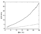
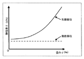
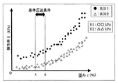
ところで、生体組織は、圧迫に対して非線形の弾性応答を示し、圧縮量などの圧迫の程度(以下、圧迫条件という。)に応じて硬さが変化することが知られている。例えば、非特許文献1によれば、図2に示すような乳腺組織の乳腺部位と脂肪部位を圧縮した際の応力(kPa)と歪み(%)の関係の実測値が報告されている。同図によれば、脂肪部位の応力―歪みは直線的な関係であるが、乳腺部位の応力―歪みの関係は非線形である。したがって、図2の応力−歪み曲線の傾きで与えられる弾性率(ヤング率)は、図3に模式的に示すように、脂肪部位は一定値であるが、乳腺部位は加えられた歪みに応じて変化することが分かる。 By the way, it is known that a living tissue exhibits a non-linear elastic response to compression, and the hardness changes according to the degree of compression such as the amount of compression (hereinafter referred to as compression condition). For example, according to Non-Patent Document 1, an actual measurement value of a relationship between stress (kPa) and strain (%) when compressing a mammary gland region and a fat region of a mammary gland tissue as shown in FIG. 2 is reported. According to the figure, the stress-strain in the fat region is a linear relationship, but the stress-strain relationship in the mammary gland region is non-linear. Therefore, the modulus of elasticity (Young's modulus) given by the slope of the stress-strain curve in FIG. 2 is a constant value in the fat region as shown schematically in FIG. 3, but the mammary gland region depends on the applied strain. It can be seen that changes.
一方、非特許文献2には、歪みと弾性率の関係のデータを取得した後、歪み−弾性率曲線を関数で近似し、最小二乗法などにより最もよく近似する曲線からその非線形性を表す非線形パラメタを抽出し、その組織の非線形性を表す情報として評価する試みが提案されている。 On the other hand, in Non-Patent Document 2, after acquiring data on the relationship between strain and elastic modulus, a strain-elastic modulus curve is approximated by a function, and the nonlinearity is expressed from a curve that is best approximated by a least square method or the like. Attempts have been made to extract parameters and evaluate them as information representing the nonlinearity of the tissue.
このように、組織の硬さの情報を用いて組織の良悪性を鑑別するにあたって、例えば弾性率がどのような圧迫条件の下で計測されたかが非常に重要な情報であり、圧縮量などの圧迫条件が大きく異なる条件で計測された診断対象については、良悪性を誤って診断してしまうことも考えられる。 Thus, in distinguishing benign and malignant tissue using tissue hardness information, for example, under what compression conditions the elastic modulus was measured is very important information, such as compression amount It is conceivable that a diagnosis target measured under greatly different conditions is erroneously diagnosed as benign or malignant.
しかしながら、特許文献1、2等に記載された従来の技術では、圧迫の程度に応じて硬さが変化する生体組織の非線形性を考慮していない。そのため、検者は様々な圧迫条件下において複数の弾性画像を取得し、その中から検者が主観的に適切と考える1又は複数の弾性画像に基づいて診断することを余儀なくされている。その結果、従来技術によれば、適切な弾性画像を選択するために経験や熟練を要し、診断の信頼性及び客観性に問題が残る。また、圧迫条件を変化させながら適切と思われる弾性画像を繰返し取得しなければならず、検者に負担がかかるとともに、検査効率が悪いという問題がある。 However, the conventional techniques described in Patent Documents 1 and 2 do not consider the non-linearity of the biological tissue whose hardness changes according to the degree of compression. Therefore, the examiner is forced to obtain a plurality of elastic images under various compression conditions and make a diagnosis based on one or more elastic images that the examiner considers subjectively appropriate. As a result, according to the prior art, experience and skill are required to select an appropriate elastic image, and problems remain in the reliability and objectivity of diagnosis. In addition, it is necessary to repeatedly acquire an elastic image that seems to be appropriate while changing the compression condition. This causes a problem that the examiner is burdened and inspection efficiency is poor.
本発明は、超音波診断装置において、検者の経験や熟練度に依存することなく、客観的で確定的な組織鑑別を可能とする弾性画像を提供することを課題とする。 An object of the present invention is to provide an elastic image that enables objective and definitive tissue differentiation without depending on the experience and skill level of an examiner in an ultrasonic diagnostic apparatus.
上記の課題を解決するため、本発明は、被検体の生体組織に圧迫を加えて超音波を送信し、前記被検体から発生する反射エコー信号を計測して得られたフレームデータを用いて、取得時刻が異なる一対の前記フレームデータに基づいて複数の計測点における生体組織の弾性情報と前記各計測点に加わる圧迫の程度に関する計測圧迫条件を求め、求めた前記計測圧迫条件が予め設定された基準圧迫条件を満たすときの前記弾性情報に基づいて弾性画像を生成して表示画面に表示することを特徴とする。 In order to solve the above problems, the present invention applies ultrasonic pressure to the body tissue of the subject, transmits ultrasonic waves, and uses frame data obtained by measuring a reflected echo signal generated from the subject, Based on a pair of the frame data having different acquisition times, the measurement compression condition regarding the elasticity information of the living tissue at a plurality of measurement points and the degree of compression applied to each measurement point is obtained, and the obtained measurement compression conditions are preset. An elasticity image is generated based on the elasticity information when a reference compression condition is satisfied, and is displayed on a display screen.
このように、各計測点に加わる計測圧迫条件が予め設定された基準圧迫条件を満たして計測及び生成された弾性画像を用いているから、検者の主観を廃することができ、検者の経験や熟練度に依存することなく、客観的で確定的な組織鑑別を可能とすることができ、かつ検査の効率を向上できる。また、診断に適した弾性画像の選定作業が不要となるから検者の負担が軽減される。 Thus, since the measurement compression condition applied to each measurement point satisfies the reference compression condition set in advance and uses the elastic image measured and generated, the subjectivity of the examiner can be abolished. Objective and definitive tissue differentiation can be made possible without depending on experience and skill level, and the efficiency of inspection can be improved. In addition, since it is not necessary to select an elastic image suitable for diagnosis, the burden on the examiner is reduced.
本発明の超音波診断装置は、被検体の生体組織に圧迫を加え超音波を送信して得られる反射エコー信号のフレームデータを取得するフレームデータ取得手段と、該フレームデータ取得手段により取得された取得時刻が異なる一対の前記フレームデータに基づいて複数の計測点における生体組織の弾性情報と前記各計測点に加わる圧迫の程度を示す計測圧迫条件を求める演算手段と、該演算手段により求められた前記弾性情報に基づいて弾性画像を生成する弾性画像生成手段と、前記演算手段により求められた前記計測圧迫条件が予め設定された基準圧迫条件を満たすか否か評価し、前記基準圧迫条件を満たす前記弾性画像を表示手段に表示させる圧迫条件評価手段とを有して構成することができる。 The ultrasonic diagnostic apparatus of the present invention acquires frame data acquisition means for acquiring frame data of a reflected echo signal obtained by applying pressure to a living tissue of a subject and transmitting ultrasonic waves, and acquired by the frame data acquisition means Based on a pair of the frame data with different acquisition times, calculation means for obtaining elasticity information of biological tissue at a plurality of measurement points and measurement compression conditions indicating the degree of compression applied to each measurement point, and the calculation means An elasticity image generating means for generating an elasticity image based on the elasticity information, and evaluating whether or not the measurement compression condition obtained by the calculation means satisfies a preset reference compression condition, and satisfies the reference compression condition The image forming apparatus may include a compression condition evaluation unit that displays the elasticity image on a display unit.
本発明の圧迫条件には、計測点の歪み、計測点の変位量、計測点の応力、被検体の体表に加えられた圧力のいずれか一つを採用することができる。なお、本発明でいう歪み及び変位量は、圧迫による生体組織の歪み変化又は変位のゼロから計測時点までの積分量をいい、その時々の歪み変化又は変位と区別する。また、基準圧迫条件は、生体組織の弾性を評価するのに適した圧迫条件を設定する。 As the compression condition of the present invention, any one of distortion at the measurement point, displacement at the measurement point, stress at the measurement point, and pressure applied to the body surface of the subject can be employed. The strain and displacement amount referred to in the present invention refers to an integrated amount from zero to the measurement point of strain change or displacement of the living tissue due to compression, and is distinguished from the strain change or displacement at that time. Moreover, the reference compression condition sets a compression condition suitable for evaluating the elasticity of the living tissue.
また、弾性情報には、弾性率、粘弾性率、弾性率の非線形性に係る非線形パラメタを採用することができる。 In addition, the elastic information can employ a non-linear parameter related to the non-linearity of the elastic modulus, viscoelastic modulus, and elastic modulus.
また、フレームデータに対応する画像領域内に設定された関心領域内の計測点について、計測圧迫条件と計測された弾性情報との関係を線図(グラフ)にして表示画面に表示することができる。この場合、線図の基準圧迫条件の位置にマークを表示することが好ましい。 In addition, the relationship between the measurement compression condition and the measured elasticity information can be displayed as a diagram (graph) on the display screen for the measurement points in the region of interest set in the image region corresponding to the frame data. . In this case, it is preferable to display a mark at the position of the reference compression condition in the diagram.
また、弾性画像に関心領域の輪郭を表示するとともに、関心領域に対応付けて関心領域内の複数の計測点の弾性情報の平均値を数値で表示することができる。弾性画像は、各画素の色相又は輝度を各弾性情報に応じて割り付けて生成される。 In addition, the contour of the region of interest can be displayed on the elastic image, and the average value of the elasticity information of a plurality of measurement points in the region of interest can be displayed numerically in association with the region of interest. The elasticity image is generated by assigning the hue or luminance of each pixel according to each elasticity information.
本発明によれば、検者の経験や熟練度に依存することなく、客観的で確定的な組織鑑別を可能とする弾性画像を提供することができる。 According to the present invention, it is possible to provide an elastic image that enables objective and definitive tissue differentiation without depending on the experience and skill level of the examiner.
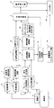
以下、本発明の弾性画像生成方法及び装置を実施形態に基づいて説明する。図1に、本発明の弾性画像生成方法を実施する一実施形態の超音波診断装置のブロック構成図を示す。図に示すように、被検体1に当接して用いられる超音波の探触子2は、被検体1との間で超音波を送信及び受信する複数の振動子を有して形成されている。探触子2は、送信回路3から供給される超音波パルスにより駆動される。送受信制御回路4は、探触子2の複数の振動子を駆動する超音波パルスの送信タイミングを制御して、被検体1内に設定される焦点に向けて超音波ビームを形成するようになっている。また、送受信制御回路4は、探触子2の振動子の配列方向に電子的に超音波ビームを走査するようになっている。
Hereinafter, an elastic image generation method and apparatus according to the present invention will be described based on embodiments. FIG. 1 is a block diagram of an ultrasonic diagnostic apparatus according to an embodiment that implements the elastic image generation method of the present invention. As shown in the figure, an ultrasonic probe 2 used in contact with a subject 1 is formed with a plurality of transducers that transmit and receive ultrasonic waves to and from the subject 1. . The probe 2 is driven by ultrasonic pulses supplied from the
一方、探触子2は、被検体1内から発生する反射エコー信号を受信して受信回路5に出力する。受信回路5は、送受信制御回路4から入力されるタイミング信号に従って、反射エコー信号を取り込んで増幅などの受信処理を行う。受信回路5により処理された反射エコー信号は、整相加算回路6において複数の振動子により受信された反射エコー信号の位相を合わせて加算することにより増幅される。整相加算回路6において整相加算された反射エコー信号は、信号処理部7に入力され、ゲイン補正、ログ圧縮、検波、輪郭強調、フィルタ処理等の信号処理がなされる。
On the other hand, the probe 2 receives a reflected echo signal generated from the subject 1 and outputs it to the
信号処理部7により処理された反射エコー信号は、白黒スキャンコンバータ8に導かれて超音波ビームの走査面に対応した2次元の断層像データ(ディジタルデータ)に変換される。これらの信号処理部7と白黒スキャンコンバータ8によって断層像(Bモード像)の画像再構成手段が構成される。白黒スキャンコンバータ8から出力される断層像データは、切替加算部9を介して画像表示器10に供給されてBモード像が表示されるようになっている。
The reflected echo signal processed by the
一方、整相加算回路6から出力される反射エコー信号は、フレームデータ取得部11に導かれる。フレームデータ取得部11は、超音波ビームの走査面(断層面)に対応する反射エコー信号群を、フレームデータとして複数フレーム分を取得してメモリなどに格納する。変位計測部12は、フレームデータ取得部11に格納されている取得時刻が異なる複数対のフレームデータを順次取り込み、取り込んだ一対のフレームデータに基づいて断層面における複数の計測点の変位ベクトルを求め、変位フレームデータとして弾性情報演算部13に出力するようになっている。
On the other hand, the reflected echo signal output from the
本実施例の弾性情報演算部13は、変位フレームデータに基づいて各計測点の生体組織の歪み変化を求める歪み演算部と、歪みフレームデータに基づいて各計測点の生体組織の弾性率を求める弾性率演算部と、歪み演算部で求めた歪み変化を積分して計測圧迫条件の一例である歪みを求める歪み演算部を有して構成されている。弾性情報演算部13にて求められた弾性率のフレームデータは弾性情報処理部14に出力され、歪みは圧迫条件評価部18に出力されるようになっている。
The elasticity
弾性情報処理部14は、弾性情報演算部13から入力される各弾性情報のフレームデータに対して、座標平面内におけるスムージング処理、コントラスト最適化処理、フレーム間における時間軸方向のスムージング処理などの様々な画像処理を施して、カラースキャンコンバータ15に送出するようになっている。
The elasticity
カラースキャンコンバータ15は、弾性情報処理部14により処理された弾性率のフレームデータを取り込み、設定された弾性率のカラーマップに従って、フレームデータの画素ごとに色調コードを付与してカラー弾性画像を生成するようになっている。
The
カラースキャンコンバータ15により生成されたカラー弾性画像は、切替加算部9を介して画像表示器10に表示されるようになっている。また、切替加算部9は、白黒スキャンコンバータ8から出力される白黒の断層像と、カラースキャンコンバータ15から出力されるカラー弾性画像とを入力し、両画像を切り替えていずれか一方を表示させる機能と、両画像の一方を半透明にして加算合成して画像表示器10に重ねて表示させる機能と、両画像を並べて表示させる機能を有して形成されている。また、切替加算部9から出力される画像データは、装置制御インターフェイス部19の制御に従ってシネメモリ20に格納されるようになっている。シネメモリ20に格納された画像データは、装置制御インターフェイス部19の制御に従って画像表示器10に表示されるようになっている。
The color elasticity image generated by the
本実施形態の特徴に係る圧迫条件評価部18は、弾性情報演算部13により求められた計測圧迫条件である歪みを取り込み、その歪みが装置制御インターフェイス部19から入力される基準圧迫条件を満たすか否か判断するようになっている。その判断の結果、取り込んだ歪みが基準圧迫条件を満たす場合は、切替加算部9に指令を送って、カラースキャンコンバータ15から出力されるカラー弾性画像を画像表示器10に出力表示させるようになっている。
The compression
このように構成される本実施形態の基本的な動作について説明する。まず、探触子2により被検体1に圧迫を加えて被検体1に超音波ビームを走査し、走査面からの反射エコー信号を連続的に受信する。そして、整相加算回路6から出力される反射エコー信号に基づいて、信号処理部7及び白黒スキャンコンバータ8により断層像が再構成され、切替加算器9を介して画像表示器10に表示される。
The basic operation of this embodiment configured as described above will be described. First, the probe 2 applies pressure to the subject 1 to scan the subject 1 with an ultrasonic beam, and continuously receives reflected echo signals from the scanning surface. Based on the reflected echo signal output from the
一方、フレームデータ取得部11は、反射エコー信号を取り込んでフレームレートに同期させてフレームデータを繰り返し取得し、内蔵されたフレームメモリ内に時系列順に保存する。そして、取得時刻が異なる一対のフレームデータを単位として、連続的に複数対のフレームデータを選択して変位計測部12に出力する。変位計測部12は、選択された一対のフレームデータを1次元もしくは2次元相関処理し、走査面における複数の計測点の変位を計測して変位フレームデータを生成する。この変位ベクトルの検出法としては、例えば特開平5−317313号公報等に記載されているブロックマッチング法又はグラジェント法が知られている。ブロックマッチング法は、画像を例えばN×N画素からなるブロックに分け、現フレーム中の着目しているブロックに最も近似しているブロックを前フレームから探索し、これに基づいて計測点の変位を求める。また、一対のRF信号フレームデータの同一領域における自己相関を計算して変位を算出することができる。
On the other hand, the frame
弾性情報演算部13は、変位フレームデータを取り込んで、各計測点の歪み変化を求め、求めた歪み変化に基づいて弾性情報である弾性率を演算し、弾性率フレームデータを弾性情報処理部14に出力する。歪み変化の演算は、公知のように変位を空間微分することによって計算される。また、求めた歪み変化に基づいて各計測点の弾性率を演算する。弾性率を求める場合は、圧力計測部17により計測された圧力の計測値を取り込み、これに基づいて各計測点における応力を演算する。圧力計側部17は、探触子2の超音波送受信面と被検体1との間に設けられた圧力センサ16により検出された圧力に基づいて、被検体1内部の計測点における応力を演算する。つまり、弾性情報演算部13の弾性率演算部は、各計測点における応力と、弾性情報演算部13で求めた歪みフレームデータから走査面上の各計測点の弾性率E(例えば、ヤング率)を演算し、弾性情報処理部14に出力する。
The elasticity
弾性情報処理部14は、入力される弾性率をスムージング処理などの処理を施してカラースキャンコンバータ15に出力する。カラースキャンコンバータ15は、弾性情報に基づいてカラー弾性画像を生成する。カラー画像は、例えば256階調化による色調のグラデーションで画素単位ごとにフレームデータの弾性率に応じて色付けされる。なお、カラースキャンコンバータ15に代えて、白黒スキャンコンバータを用いることができる。この場合は、弾性率が大きい領域は輝度を明るく、逆に小さい領域は輝度を暗くするなどにより、良性又は悪性を鑑別できるようにすることができる。
The elastic
以下に、本実施形態を用いて本発明の弾性画像生成方法を実施する具体的な実施例を説明する。なお、各実施例は、本実施形態の特徴部である弾性情報演算部13、圧迫条件評価部18、装置制御インターフェイス部19及びシネメモリ20等により実施される。
Below, the specific Example which implements the elastic image generation method of this invention using this embodiment is described. In addition, each Example is implemented by the elasticity
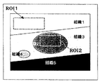
本発明の弾性画像生成方法の一実施例として、図4に示す生体組織1〜5を含む部位に圧迫を加えて弾性画像を生成する場合を説明する。本実施例では、弾性情報演算部13において弾性フレームデータとして生体組織1〜5の各部位における計測点の弾性率を弾性情報として求めるものとする。なお、図4は、弾性フレームデータと弾性画像との位置関係を対応付けるために、1フレームの画像の体裁で示している。
As an embodiment of the elastic image generation method of the present invention, a case will be described in which an elastic image is generated by applying pressure to a site including biological tissues 1 to 5 shown in FIG. In the present embodiment, the elasticity
まず、圧迫条件評価部18には、装置制御インターフェイス部19から検者によって関心領域(以下、ROIという。)としてROI1、ROI2が入力設定される。圧迫条件評価部18は、弾性情報演算部13からROI1、ROI2の中に分布する各計測点の弾性率データ(弾性率の数値データ)と、ROI1、ROI2の中に分布する各計測点の歪みの数値データを取り込む。本実施例では、圧迫の程度を評価するための圧迫条件として歪みを用いている。また、歪み(ε=ΣΔε)は、圧縮ゼロから現時点までの歪み変化の積分値であり、一対のフレームデータ間ごとに得られる歪み変化(Δε)とは区別する。
First, ROI1 and ROI2 are input and set as an area of interest (hereinafter referred to as ROI) by the examiner from the device
圧迫条件評価部18は、取り込んだ歪みと弾性率に基づいて、ROI1、ROI2のそれぞれについて、例えば、歪みε(%)の平均値と弾性率E(kPa)の平均値を演算し、それらの関係を図5に示すようにグラフにプロットする。そして、歪み(圧迫条件)−弾性情報(弾性率)曲線のグラフ画像を構築し、圧迫条件評価部18に記憶するとともに、切替加算部9に送出して画像表示器10に表示する。これにより、画像表示器10には、ROI1、ROI2内の組織に関する圧迫条件−弾性情報曲線がグラフ画像として表示される。
The compression
例えば、基準圧迫条件を歪み4〜6%に設定すると、図5に示すように、基準圧迫条件の範囲が圧迫条件−弾性情報曲線に表示される。一方、圧迫条件評価部18は、基準圧迫条件を満たした時点において計測されたROI1、ROI2の弾性率E1、E2を解析する。そして、図4に示したROI1、ROI2に対応する組織の弾性診断結果として、図5に示すように弾性率E1、E2の数値データをグラフ画像に表示して、ROI1、ROI2の基準圧迫条件を満たすときの弾性率を弾性診断結果として確定する。なお、一般に、ROI1とROI2の計測圧迫条件は異なることがあるから、基準圧迫条件が同じであっても、同じ計測時刻においてROI1とROI2が基準圧迫条件を満たすというわけではない。
For example, when the reference compression condition is set to a strain of 4 to 6%, the range of the reference compression condition is displayed on the compression condition-elasticity information curve as shown in FIG. On the other hand, the compression
ここで、基準圧迫条件は、範囲として設定する方法に限らない。例えば、歪み5%を基準圧迫条件として設定し、この歪み5%を跨ぐ前後において計測された弾性率の値から線形補間することにより歪み5%における弾性率の値を求めるようにすることができる。 Here, the reference compression condition is not limited to the method of setting as a range. For example, the elastic modulus value at 5% strain can be obtained by setting 5% strain as the standard compression condition and linearly interpolating from the elastic modulus values measured before and after the 5% strain. .
また、例えば、圧迫操作を繰り返して行う弾性情報を計測する過程で、基準圧迫条件を満たして計測された弾性率の値により、基準圧迫条件を満たすたびに図5の弾性率を更新するようにすることができる。また、基準圧迫条件を満たして計測された現在までの弾性率の値との加算平均値を表示させるようにすることができる。 Further, for example, in the process of measuring the elasticity information by repeatedly performing the compression operation, the elastic modulus in FIG. 5 is updated every time the reference compression condition is satisfied by the value of the elastic modulus measured by satisfying the reference compression condition. can do. In addition, it is possible to display the addition average value with the value of the elastic modulus up to the present measured while satisfying the reference compression condition.
また、本実施例では、弾性情報としてヤング率に代表される弾性率を例に示したが、粘弾性率、非線形性などの組織の弾性特性に基づいた指標であれば用いることができる。 In this embodiment, the elastic modulus represented by the Young's modulus is shown as an example of the elasticity information. However, any index based on the elastic characteristics of the tissue such as viscoelastic modulus and nonlinearity can be used.
また、計測圧迫条件は、ROI内の歪みに限らず、変位計測部12で計測された変位量(変位ゼロからの積算を含む)、圧力計測部12で計測された圧迫の圧力に基づいて導出されたROI内に伝わった応力など、圧迫の状態を反映した情報を用いることができる。
The measurement compression condition is not limited to the strain in the ROI, but is derived based on the amount of displacement (including integration from zero displacement) measured by the
上述したように、本実施例によれば、生体組織の画像にROIを設定して弾性情報の計測操作を実施するだけで、そのROIに対応する組織に加えられる計測圧迫条件が評価に適切な基準圧迫条件を満たしているときに取得された弾性情報である弾性率が数値により表示される。したがって、経験や熟練がない検者であっても、ROIに係る生体組織の適切な弾性情報を得ることができるから、信頼性及び客観性を有する診断を行うことができる。また、圧迫条件を変化させながら適切と思われる弾性画像を繰返し取得する操作が不要となり、検者の負担を軽減して、検査効率を向上できる。また、本実施例によれば、超音波によるリアルタイム性を損なうことなく、確定的な診断情報を臨床現場において効率よく取得することができる。 As described above, according to this embodiment, the measurement compression condition applied to the tissue corresponding to the ROI is appropriate for the evaluation only by setting the ROI to the image of the living tissue and performing the elastic information measurement operation. The elastic modulus, which is elastic information acquired when the reference compression condition is satisfied, is displayed as a numerical value. Therefore, even an examiner who has no experience or skill can obtain appropriate elasticity information of a living tissue related to ROI, and thus a diagnosis with reliability and objectivity can be performed. Further, it is not necessary to repeatedly acquire an elastic image that seems to be appropriate while changing the compression condition, thereby reducing the burden on the examiner and improving the examination efficiency. Further, according to the present embodiment, definitive diagnostic information can be efficiently acquired at the clinical site without impairing the real-time property of ultrasonic waves.
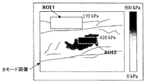
実施例1では、ROIの弾性情報を数値データとして画像に出力する例を示した。しかし、本発明により生成する弾性画像は、これに限られるものではなく、図6に示す実施例2のように、基準圧迫条件を満たした時点において計測されたROI内の弾性率に基づき、弾性率に応じてROI内の画像を階調化した弾性画像を生成して表示することができる。 In the first embodiment, the example in which the ROI elasticity information is output as numerical data to the image is shown. However, the elasticity image generated according to the present invention is not limited to this, and based on the elastic modulus in the ROI measured at the time when the reference compression condition is satisfied, as in Example 2 shown in FIG. It is possible to generate and display an elastic image obtained by gradationizing the image in the ROI according to the rate.
例えば、実施例1で設定したROI内の計測圧迫条件が基準圧迫条件を満たしたときに、ROI内において計測された弾性率の大きさに応じて、白黒輝度又は色相に階調を与えた画像を生成して表示する。このとき、弾性率の数値データとひずみの数値データも画像上に表示するようにしてもよい。 For example, when the measurement compression condition in the ROI set in the first embodiment satisfies the reference compression condition, an image in which gradation is given to black and white luminance or hue according to the magnitude of the elastic modulus measured in the ROI Is generated and displayed. At this time, the numerical value data of the elastic modulus and the numerical value data of the strain may be displayed on the image.
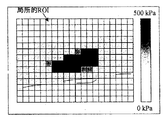
実施例2では、各ROIについて、各計測点に対応する画素単位で弾性率を階調化して表示する例を説明した。しかし、図7の実施例3に示すように、実施例2のROIに代えて、計測領域の全体に画素を構築できる程度の小さな局所的ROIを格子状に複数配置することができる。この場合は、各局所的ROI毎に独立に、計測圧迫条件が基準圧迫条件を満たしたときの各局所的ROIの弾性率の大きさを求め、局所的ROIごとに白黒輝度又は色相に階調を与えて、観測領域全域にわたって弾性画像を形成して表示する。なお、局所的ROIは、1又は複数の計測点を含む領域として設定することができる。 In the second embodiment, the example in which the elastic modulus is displayed in gradation for each ROI in units of pixels corresponding to each measurement point has been described. However, as shown in the third embodiment of FIG. 7, instead of the ROI of the second embodiment, a plurality of small local ROIs capable of constructing pixels in the entire measurement region can be arranged in a grid pattern. In this case, the elastic modulus of each local ROI when the measured compression condition satisfies the reference compression condition is determined independently for each local ROI, and the gradation is changed to monochrome luminance or hue for each local ROI. And an elastic image is formed and displayed over the entire observation region. The local ROI can be set as a region including one or a plurality of measurement points.
また、基準圧迫条件を満たして割当てられた各局所的ROIの弾性画像の階調は、繰り返し計測される弾性率の計測圧迫条件が基準圧迫条件を満たすたびに更新して表示されるようにすることができる。また、基準圧迫条件を満たして取得されたこれまでの弾性率の値の加算平均値に基づいて、弾性画像の階調を更新して表示すれば、弾性画像の精度を向上させることができる。 Further, the gradation of the elasticity image of each local ROI assigned to satisfy the reference compression condition is updated and displayed every time the measurement compression condition of the elastic modulus repeatedly measured satisfies the reference compression condition. be able to. Further, if the gradation of the elastic image is updated and displayed based on the addition average value of the elastic modulus values obtained so far while satisfying the reference compression condition, the accuracy of the elastic image can be improved.
また、計測中に計測圧迫条件が基準圧迫条件を満たさなかったROIについては、弾性率の大きさを反映した階調が付与されないようにすれば、弾性評価不可能であったことを認識できる。 Further, it can be recognized that the elasticity evaluation is impossible if the gradation reflecting the magnitude of the elastic modulus is not given to the ROI whose measurement compression condition does not satisfy the reference compression condition during measurement.
実施例1〜3では、弾性情報として弾性率を用いる例を説明した。本実施例4では、図3に示した歪み−弾性率曲線の非線形性を表す非線形パラメタを弾性情報として画像化する例を説明する。つまり、計測圧迫条件が基準圧迫条件を満たした場合における各計測点の非線形パラメタの値を求め、求めた非線形パラメタに基づいて階調化した弾性画像を生成する。 In Examples 1 to 3, an example in which the elastic modulus is used as the elastic information has been described. In the fourth embodiment, an example will be described in which a nonlinear parameter representing the nonlinearity of the strain-elastic modulus curve shown in FIG. 3 is imaged as elasticity information. That is, the value of the nonlinear parameter at each measurement point when the measurement compression condition satisfies the reference compression condition is obtained, and an elastic image that is gradated based on the obtained nonlinear parameter is generated.
前述したとおり、非特許文献1には、乳腺組織の弾性特性の非線形性に関して、脂肪組織は大きな歪みの範囲までほぼ一定の弾性率の線形な応答を示すのに対し、繊維組織や浸潤性腫瘍は歪みの増加に伴い弾性率も顕著に増加する歪み硬化が認められることが報告されている。また、繊維組織よりも浸潤性の悪性腫瘍の方が、歪み硬化の程度が大きく、非線形の程度も大きくなる。また、一般に生体組織は非線形の弾性応答を示し、例えば、歪み−弾性率の関係は、図3に示した曲線に従うことが知られている。非特許文献2には、この歪みと弾性率の関係のデータを取得した後、所定の関数でその曲線を近似し、最小二乗法などにより最もよく近似する曲線からその非線形パラメタを抽出し、その組織の非線形性を表す情報として評価する試みが提案されている。 As described above, Non-Patent Document 1 discloses that adipose tissue exhibits a linear response with a substantially constant elastic modulus up to a large strain range with respect to the nonlinearity of the elastic characteristics of the mammary gland tissue, whereas fiber tissue and invasive tumors. It has been reported that strain hardening in which the elastic modulus increases remarkably as strain increases is observed. In addition, infiltrative malignant tumors have a greater degree of strain hardening and non-linearity than fiber tissues. In general, living tissue exhibits a non-linear elastic response. For example, it is known that the relationship between strain and elastic modulus follows the curve shown in FIG. In Non-Patent Document 2, after acquiring the data of the relationship between the strain and the elastic modulus, the curve is approximated with a predetermined function, and the nonlinear parameter is extracted from the curve that is best approximated by the least square method or the like. Attempts to evaluate it as information representing the nonlinearity of the organization have been proposed.
つまり、非特許文献2によれば、Eをヤング率と歪みε(=ΣΔε)の非線形性を解析する目的において、圧迫に対する組織の応答の曲線を、次式(1)のように1次関数として仮定している。 That is, according to Non-Patent Document 2, for the purpose of analyzing the nonlinearity of Young's modulus and strain ε (= ΣΔε) as E, the response curve of the tissue to compression is expressed by a linear function as in the following equation (1). Assumes that
E=E0+α×ε (1)
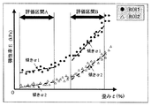
ここで、E0は一定値、αは非線形パラメタであり、ヤング率−歪み曲線の傾きである。しかし、図8に示すように、大きな歪みになるほど、実際の組織の非線形性が顕著になり、非線形パラメタαは圧迫条件に大きく依存する。したがって、(1)式のようにEがεの1次関数であるとする仮定する非線形パラメタαは、評価区間を定めなければ定量情報とは成り得ず、確定診断には採用できない。
E = E0 + α × ε (1)
Here, E0 is a constant value, α is a nonlinear parameter, and is the slope of the Young's modulus-strain curve. However, as shown in FIG. 8, as the strain becomes larger, the actual tissue nonlinearity becomes more prominent, and the nonlinear parameter α greatly depends on the compression condition. Therefore, the nonlinear parameter α that assumes that E is a linear function of ε as in equation (1) cannot be quantitative information unless an evaluation interval is defined, and cannot be adopted for definitive diagnosis.
そこで、本実施例では、実施例1〜3と同様、基準圧迫条件を設定し、計測圧迫条件が基準圧迫条件を満たして計測された弾性率と歪みとのデータに基づいて非線形パラメタαを求め、求めた非線形パラメタαを数値情報や画像情報として検者に提供するようにすることを特徴とする。具体的には、実施例1〜3における「弾性率」を「非線形パラメタ」に置き換えればよい。 Therefore, in this embodiment, as in Embodiments 1 to 3, the reference compression condition is set, and the nonlinear parameter α is obtained based on the data of the elastic modulus and strain measured when the measurement compression condition satisfies the reference compression condition. The obtained nonlinear parameter α is provided to the examiner as numerical information or image information. Specifically, “elastic modulus” in Examples 1 to 3 may be replaced with “nonlinear parameter”.
さらに、非線形パラメタαを一層忠実に求めるためには、広範囲の計測圧迫条件において、組織の非線形応答を忠実に近似する曲線として、次式(2)に示す高次の関数により近似することが好ましい。γは、2以上の自然数である。 Furthermore, in order to obtain the nonlinear parameter α more faithfully, it is preferable to approximate it by a higher-order function represented by the following equation (2) as a curve that faithfully approximates the nonlinear response of the tissue in a wide range of measurement compression conditions. . γ is a natural number of 2 or more.
E=E0+α×εγ (2)
(2)式による非線形パラメタαも、組織の非線形性が大きいほど大きな値となり、線形に近づくほど限りなくゼロに近くなる。さらに、一般化すると、次式(3)の指数関数で近似できる。
E = E0 + α × ε γ (2)
The nonlinear parameter α according to the equation (2) also becomes a larger value as the nonlinearity of the tissue is larger, and becomes closer to zero as it approaches the linearity. Furthermore, when generalized, it can be approximated by an exponential function of the following equation (3).
E=(E0−1)+ exp(α×ε) (3)
これらの式(2)、(3)で示される関係式を仮定すれば、計測圧迫条件の評価区間を任意に設定しても、高精度に確定した非線形パラメタαを得ることができ、定量的な評価が実現できる。
E = (E0-1) + exp (α × ε) (3)
Assuming the relational expressions shown in these equations (2) and (3), the nonlinear parameter α determined with high accuracy can be obtained even if the evaluation interval of the measurement compression condition is arbitrarily set. Can be evaluated.
例えば、従来は、図8のようにαの値が圧迫条件に依存するため、歪み−弾性率の関係のデータを蓄積した後、オフライン処理により計測圧迫条件について適当な評価区間を確認して解析する必要がある。この点、本実施例によれば、計測圧迫条件に依存しない確定的な非線形パラメタαが得られる。つまり、時刻t(0)において計測された歪み−弾性率の関係の(ε(0)、E(0))と、過去の時刻t(−1)、t(−2)、…において得られた歪み−弾性率の関係(ε(−1)、E(−1))、(ε(−2)、Y(−2))、 …を歪み−弾性率の関係の蓄積データとして適用し、時刻t(0)においてリアルタイムに非線形パラメタαを評価しても、その非線形パラメタαの数値情報、画像情報は圧迫条件に依存しない客観的な情報として得ることができる。 For example, conventionally, the value of α depends on the compression condition as shown in FIG. 8. Therefore, after accumulating the strain-elastic modulus relationship data, an appropriate evaluation interval is confirmed and analyzed for the measurement compression condition by offline processing. There is a need to. In this regard, according to the present embodiment, a deterministic nonlinear parameter α that does not depend on the measurement compression condition can be obtained. That is, the strain-elastic modulus relationship (ε (0), E (0)) measured at time t (0) and the past times t (−1), t (−2),. Applied strain-elastic modulus relationships (ε (−1), E (−1)), (ε (−2), Y (−2)),... As accumulated data of strain-elastic modulus relationships, Even if the nonlinear parameter α is evaluated in real time at the time t (0), numerical information and image information of the nonlinear parameter α can be obtained as objective information independent of the compression condition.
したがって、本実施例4によれば、図7で説明した場合と同様、非線形パラメタαを弾性情報とし、リアルタイムの弾性画像を生成して表示することが可能である。その結果、例えば、Bモード像や弾性率画像によって認識できない悪性組織であっても、非線形パラメタの評価によってのみ異常な組織を検出することができる場合があるので、このような場合に検査において異常組織領域を見逃してしまうことはなく、検者の主観に依らない診断を行うことができる。 Therefore, according to the fourth embodiment, as in the case described with reference to FIG. 7, it is possible to generate and display a real-time elasticity image using the nonlinear parameter α as elasticity information. As a result, for example, even in a malignant tissue that cannot be recognized by a B-mode image or an elastic modulus image, an abnormal tissue may be detected only by evaluating a nonlinear parameter. The tissue region is not overlooked, and diagnosis independent of the subjectivity of the examiner can be performed.
実施例1〜3においては、ROIに属する組織が圧迫操作により移動することについて考慮していない。本実施例5では、圧迫操作により移動する組織に追従させてROIを移動させて、弾性情報の評価の精度を向上させる。つまり、画像に対するROIの位置を固定すると、図9(a)〜(c)に示すように、圧迫操作の経過に応じてROI(t0)、ROI(t1)、ROI(t2)内に入ってくる組織が変化してしまうことがあり、計測値の精度が悪くなる。 In Examples 1-3, it does not consider about the structure | tissue which belongs to ROI moving by compression operation. In the fifth embodiment, the ROI is moved following the tissue that is moved by the compression operation, thereby improving the accuracy of evaluation of the elastic information. That is, when the position of the ROI with respect to the image is fixed, as shown in FIGS. 9A to 9C, the ROI enters the ROI (t0), ROI (t1), and ROI (t2) as the compression operation progresses. The coming tissue may change, and the accuracy of the measured value will deteriorate.
そこで、本実施例5では、図9(a’)〜(c’)に示すように、圧迫の程度に応じて、ROI内に属する組織の行き先を追従して、ROI(t0)、ROI(t1)、ROI(t2)を移動させることにより、任意の圧迫条件の下において、同一組織領域の情報のみを抽出することが可能となる。その結果、評価精度を向上させることが可能になる。なお、組織の動きに追従させてROIを移動させる処理は、前述した組織の変位ベクトルを求めるブロックマッチング法又はグラジェント法を適用することができる。また、局所的ROIや計測点についても、組織の移動に応じて追従させることができる。 Therefore, in the fifth embodiment, as shown in FIGS. 9 (a ′) to (c ′), according to the degree of compression, the destination of the tissue belonging to the ROI is tracked, and ROI (t0), ROI ( By moving the t1) and ROI (t2), it becomes possible to extract only information on the same tissue region under an arbitrary compression condition. As a result, it is possible to improve the evaluation accuracy. In addition, the block matching method or the gradient method which calculates | requires the displacement vector of the structure | tissue mentioned above can be applied to the process which follows the movement of a structure | tissue and moves ROI. Further, the local ROI and the measurement point can be followed according to the movement of the tissue.
ここで、上記実施例1〜5等により生成された歪み−弾性率曲線のグラフ画像、基準圧迫条件を満たしたときの弾性率画像、非線形パラメタα画像等の弾性画像を、画像表示器10に表示する際の表示形態の実施例について説明する。
Here, the graphic image of the strain-elastic modulus curve generated by the first to fifth embodiments, the elastic image when the reference compression condition is satisfied, and the elastic image such as the nonlinear parameter α image are displayed on the
切替加算部9と画像表示器10の機能により、2画面を同時に表示可能にすれば、例えば、右画面に現時刻におけるBモード像や弾性画像をリアルタイムで表示し、左画面に計測圧迫条件−弾性情報のグラフ、基準圧迫条件を満たして計測された弾性画像、もしくは非線形パラメタ画像を表示することができる。また、複数画面の内のいずれかに圧迫条件に依存しない定量の弾性情報を表示する画像を表示することができる。
If two screens can be displayed simultaneously by the functions of the
このように、表示画像の組み合わせは、その他にもカラードプラなど従来の診断画像を含め、任意に選択できるようにすることができる。また、一つの画面に左右に並べて表示する方法に限らず、上下に並べて表示してもよい。さらに、一つの画面内に設けた小窓に別の画像を表示するような形式を採用することもできる。 In this manner, the combination of display images can be arbitrarily selected including conventional diagnostic images such as color Doppler. Moreover, the display method is not limited to the left and right side display on one screen, and may be displayed side by side. Furthermore, it is possible to adopt a format in which another image is displayed in a small window provided in one screen.
一般に、リアルタイム弾性画像の計測においては、超音波診断装置にフリーズ指令を与えると、フリーズまでに取得された時間的に連続した所定フレーム数の弾性画像がシネメモリ20に確保される。そして、シネメモリ20に確保された弾性画像を連続的に読み出して画像表示器10に動画として表示することができるようになっている。
In general, in the measurement of a real-time elasticity image, when a freeze command is given to the ultrasonic diagnostic apparatus, a predetermined number of frames of elasticity images acquired until the freeze are secured in the
そこで、本実施例7では、圧迫操作を行いながら計測した複数の弾性画像をシネメモリ20に格納するとともに、基準圧迫条件を満たした計測圧迫条件で得られた弾性画像のフレームに、基準圧迫条件を満たした弾性画像であることを示すマークを表示するようにする。例えば、基準圧迫条件を満たした弾性画像には、丸印(○)を画像のどこかに表示する。また、基準圧迫条件に対して計測圧迫条件が小さければ上向きの矢印(↑)を、大きければ下向きの矢印(↓)を、弾性画像に表示する。また、それらのマーク表示に代えて又はマーク表示と共に、音声によって検者に報知するようにしてもよい。
Therefore, in the seventh embodiment, a plurality of elasticity images measured while performing the compression operation are stored in the
本実施例によれば、検者は、超音波診断装置からリアルタイムにフィードバックされるガイド情報により、計測圧迫条件が基準圧迫条件を満たす方向に調整することができるから、適切な弾性画像を取得することが可能となる。また、同時に、診断に適用する画像や弾性に関する数値情報を検者の主観によらずに確定的に決定することができる。 According to the present embodiment, the examiner can adjust the measurement compression condition in the direction satisfying the reference compression condition by the guide information fed back in real time from the ultrasonic diagnostic apparatus, and thus acquires an appropriate elasticity image. It becomes possible. At the same time, it is possible to deterministically determine the numerical information related to the image and elasticity applied to the diagnosis without depending on the subjectivity of the examiner.
実施例7では、本発明の弾性画像生成方法によりリアルタイムで生成された弾性画像を、画像表示器10に連続的に表示する例を示したが、本発明はこれに限らず、計測圧迫条件が基準圧迫条件を満たしたときの弾性情報に対応する弾性画像のみを生成して画像表示器10に表示するようにする。つまり、計測圧迫条件が基準圧迫条件を満たさない弾性画像は表示しないようにする。
In the seventh embodiment, an example in which the elasticity image generated in real time by the elasticity image generation method of the present invention is continuously displayed on the
実施例7では、基準圧迫条件に対する計測圧迫条件の大小に応じて弾性画像にマークを表示するようにしたが、本発明はこれに限らず、計測圧迫条件が基準圧迫条件に近づくほど、カラー弾性画像の明るさが強くなるなど、弾性画像の見易さが増加するなどの工夫をすることができる。例えば、Bモード像に半透明のカラー弾性画像を重ね合わせた画像を生成する場合は、カラー弾性画像のブレンディング比率を計測圧迫条件が基準圧迫条件に近づくほど大きくするようにすることもできる。 In the seventh embodiment, the mark is displayed on the elastic image according to the magnitude of the measurement compression condition relative to the reference compression condition. However, the present invention is not limited to this, and the color elasticity increases as the measurement compression condition approaches the reference compression condition. It is possible to devise measures such as increasing the brightness of the image and increasing the visibility of the elastic image. For example, when an image in which a translucent color elastic image is superimposed on a B-mode image is generated, the blending ratio of the color elastic image can be increased as the measured compression condition approaches the reference compression condition.
また、計測圧迫条件が基準圧迫条件を満たしたときの弾性画像、関心部位の弾性率の数値情報、その他診断の判断材料となる情報は、弾性診断の結果として、超音波診断装置に備えられている各患者の診断レポート機能に自動的に反映するようにすることができる。 In addition, the elasticity image when the measurement compression condition satisfies the reference compression condition, the numerical information of the elastic modulus of the region of interest, and other information used as a judgment material for diagnosis are provided in the ultrasonic diagnostic apparatus as a result of the elasticity diagnosis. It can be automatically reflected in the diagnostic report function of each patient.
また、上記の各実施例においては、対象組織を圧迫することにより弾性情報を取得する例について説明したが、本発明の弾性画像生成方法は、例えば、加振映像法(Y. Yamakoshi et al : Ultrasonic Imaging of Internal Vibration of Soft Tissue under Forced Vibration, IEEE Trans UFFC 1990; 37; 45-53.)などの手法によって得られた弾性情報に対しても適用することができる。 Further, in each of the above-described embodiments, the example in which the elasticity information is acquired by compressing the target tissue has been described. However, for example, the elastic image generation method of the present invention may be an excitation video method (Y. Yamakoshi et al: It can also be applied to elasticity information obtained by techniques such as Ultrasonic Imaging of Internal Vibration of Soft Tissue under Forced Vibration, IEEE Trans UFFC 1990; 37; 45-53.).
1 被検体
2 探触子
3 送信回路
4 送受信制御回路
5 受信回路
6 整相加算回路
7 信号処理部
8 白黒スキャンコンバータ
9 切替加算部
10 画像表示器
11 フレームデータ取得部
12 変位計測部
13 弾性情報演算部
15 カラースキャンコンバータ
16 圧力センサ
17 圧力計測部
18 圧迫条件評価部
19 装置制御インターフェイス部
20 シネメモリ
DESCRIPTION OF SYMBOLS 1 Subject 2
Claims (8)
前記圧迫条件評価手段は、前記フレームデータに対応する画像領域内に設定された関心領域内の前記計測点における前記計測圧迫条件と該計測圧迫条件に対応する前記弾性情報との関係のグラフ画像を生成し、該グラフ画像の前記基準圧迫条件に対応する位置にマークを表示して前記表示画面に表示させることを特徴とする超音波診断装置。 The ultrasonic diagnostic apparatus according to claim 2,
The compression condition evaluation unit is configured to display a graph image of a relationship between the measurement compression condition at the measurement point in the region of interest set in the image region corresponding to the frame data and the elasticity information corresponding to the measurement compression condition. An ultrasonic diagnostic apparatus generated and displayed on the display screen by displaying a mark at a position corresponding to the reference compression condition of the graph image.
前記圧迫条件評価手段は、前記関心領域内の複数の計測点の前記弾性情報の平均値を前記グラフ画像に数値で表示することを特徴とする超音波診断装置。 The ultrasonic diagnostic apparatus according to claim 3.
The ultrasonic diagnostic apparatus, wherein the compression condition evaluation unit displays an average value of the elasticity information of a plurality of measurement points in the region of interest as a numerical value on the graph image.
前記圧迫条件評価手段は、前記弾性画像に前記関心領域を表示し、かつ該関心領域に対応付けて該関心領域内の複数の計測点の前記弾性情報の平均値を数値で表示することを特徴とする超音波診断装置。 The ultrasonic diagnostic apparatus according to claim 2,
The compression condition evaluation means displays the region of interest on the elasticity image, and displays the average value of the elasticity information of a plurality of measurement points in the region of interest as a numerical value in association with the region of interest. Ultrasonic diagnostic equipment.
前記計測圧迫条件は、前記計測点の歪み、前記計測点の変位量、前記計測点の応力、前記被検体の体表に加えられた圧力のいずれか一つであり、
前記弾性情報は、弾性率、粘弾性率、弾性率の非線形性に係る非線形パラメタ、ヒステリシスのいずれか一つであることを特徴とする超音波診断装置。 The ultrasonic diagnostic apparatus according to claim 2,
The measurement compression condition is any one of distortion of the measurement point, displacement amount of the measurement point, stress of the measurement point, and pressure applied to the body surface of the subject,
The ultrasonic diagnostic apparatus, wherein the elastic information is any one of an elastic modulus, a viscoelastic modulus, a non-linear parameter related to non-linearity of an elastic modulus, and hysteresis.
前記圧迫条件評価手段は、前記演算手段により求められた前記計測圧迫条件が予め設定された基準圧迫条件を満たすか否か評価し、前記基準圧迫条件を満たす前記弾性画像にその旨を表示するマークを付するとともに、前後の複数の前記弾性画像に前記計測圧迫条件が前記基準圧迫条件よりも小さいか大きいかを表示するマークを付して前記表示手段に表示させることを特徴とする超音波診断装置。 The ultrasonic diagnostic apparatus according to claim 2,
The compression condition evaluation means evaluates whether or not the measurement compression condition obtained by the calculation means satisfies a preset reference compression condition, and displays a mark to that effect on the elastic image satisfying the reference compression condition And a mark for displaying whether the measured compression condition is smaller or larger than the reference compression condition is displayed on the plurality of front and back elastic images and displayed on the display means. apparatus.
前記圧迫条件評価手段は、前記演算手段により求められた前記計測圧迫条件が予め設定された基準圧迫条件を満たすか否か評価し、前記基準圧迫条件を満たす前記弾性画像の輝度又は色相と、前後の複数の前記弾性画像の輝度又は色相を異ならせて前記表示手段に表示させることを特徴とする超音波診断装置。 The ultrasonic diagnostic apparatus according to claim 2,
The compression condition evaluation unit evaluates whether or not the measurement compression condition obtained by the calculation unit satisfies a preset reference compression condition, and the luminance or hue of the elastic image that satisfies the reference compression condition, A plurality of the elastic images are displayed on the display unit with different luminances or hues.
Priority Applications (1)
| Application Number | Priority Date | Filing Date | Title |
|---|---|---|---|
| JP2006115120A JP4966578B2 (en) | 2006-04-19 | 2006-04-19 | Elastic image generation method and ultrasonic diagnostic apparatus |
Applications Claiming Priority (1)
| Application Number | Priority Date | Filing Date | Title |
|---|---|---|---|
| JP2006115120A JP4966578B2 (en) | 2006-04-19 | 2006-04-19 | Elastic image generation method and ultrasonic diagnostic apparatus |
Publications (2)
| Publication Number | Publication Date |
|---|---|
| JP2007282932A true JP2007282932A (en) | 2007-11-01 |
| JP4966578B2 JP4966578B2 (en) | 2012-07-04 |
Family
ID=38755229
Family Applications (1)
| Application Number | Title | Priority Date | Filing Date |
|---|---|---|---|
| JP2006115120A Active JP4966578B2 (en) | 2006-04-19 | 2006-04-19 | Elastic image generation method and ultrasonic diagnostic apparatus |
Country Status (1)
| Country | Link |
|---|---|
| JP (1) | JP4966578B2 (en) |
Cited By (25)
| Publication number | Priority date | Publication date | Assignee | Title |
|---|---|---|---|---|
| JP2008073417A (en) * | 2006-09-25 | 2008-04-03 | Hitachi Medical Corp | Ultrasonic diagnostic device |
| WO2009063691A1 (en) * | 2007-11-16 | 2009-05-22 | Hitachi Medical Corporation | Ultrasonic imaging system |
| JP2009195613A (en) * | 2008-02-25 | 2009-09-03 | Toshiba Corp | Ultrasonic diagnostic apparatus, ultrasonic image processor, and ultrasonic image processing program |
| JP2010099292A (en) * | 2008-10-24 | 2010-05-06 | Ge Medical Systems Global Technology Co Llc | Ultrasonic diagnostic apparatus |
| JP2010162125A (en) * | 2009-01-14 | 2010-07-29 | Toshiba Medical Systems Corp | Ultrasonic diagnostic apparatus, image processing device, and control program of ultrasonic diagnostic apparatus |
| JP2010193944A (en) * | 2009-02-23 | 2010-09-09 | Konica Minolta Medical & Graphic Inc | Ultrasonic diagnostic apparatus |
| JP2010274114A (en) * | 2009-05-29 | 2010-12-09 | General Electric Co <Ge> | System and method for scaling strain image data |
| WO2011010626A1 (en) * | 2009-07-24 | 2011-01-27 | 株式会社 日立メディコ | Ultrasound diagnosis device, methods for saving/reproducing an elasticity image, and program for saving/reproducing an elasticity image |
| WO2011034005A1 (en) * | 2009-09-16 | 2011-03-24 | 株式会社 日立メディコ | Ultrasonograph, elastic image classification method, and elastic image classification program |
| JP2011067546A (en) * | 2009-09-28 | 2011-04-07 | Fujifilm Corp | Ultrasonic diagnostic apparatus and method for calculating elasticity index |
| KR20110044710A (en) * | 2009-10-23 | 2011-04-29 | 지이 메디컬 시스템즈 글로발 테크놀러지 캄파니 엘엘씨 | Ultrasonic diagnosis device |
| KR20110046328A (en) * | 2009-10-27 | 2011-05-04 | 지이 메디컬 시스템즈 글로발 테크놀러지 캄파니 엘엘씨 | Ultrasound diagnostic device |
| JP2011101729A (en) * | 2009-11-11 | 2011-05-26 | Ge Medical Systems Global Technology Co Llc | Ultrasonic diagnostic apparatus |
| KR101048554B1 (en) * | 2008-03-28 | 2011-07-11 | 연세대학교 산학협력단 | Ultrasonic Tissue Elasticity and Curing Measurement System |
| JP2012019873A (en) * | 2010-07-13 | 2012-02-02 | Ge Medical Systems Global Technology Co Llc | Ultrasonograph and control program thereof |
| JP2012061317A (en) * | 2011-11-18 | 2012-03-29 | Ge Medical Systems Global Technology Co Llc | Ultrasonic diagnostic apparatus |
| JP2013183982A (en) * | 2012-03-09 | 2013-09-19 | Hitachi Aloka Medical Ltd | Ultrasonic diagnostic apparatus and elastic image generation method |
| JP5400773B2 (en) * | 2008-06-16 | 2014-01-29 | 株式会社日立メディコ | Ultrasonic diagnostic apparatus, ultrasonic image display method, and ultrasonic diagnostic program |
| KR20140024228A (en) | 2012-08-20 | 2014-02-28 | 지이 메디컬 시스템즈 글로발 테크놀러지 캄파니 엘엘씨 | Ultrasonic diagnostic apparatus and control program thereof |
| KR20140070436A (en) | 2012-11-30 | 2014-06-10 | 지이 메디컬 시스템즈 글로발 테크놀러지 캄파니 엘엘씨 | Ultrasonic diagnosis apparatus and program for controlling the same |
| JP2015042344A (en) * | 2009-09-10 | 2015-03-05 | 学校法人上智学院 | Displacement measurement device and ultrasonic diagnostic device |
| JP5789593B2 (en) * | 2010-02-17 | 2015-10-07 | 株式会社日立メディコ | Elasticity image quality evaluation method and ultrasonic diagnostic apparatus |
| WO2016033151A1 (en) | 2014-08-27 | 2016-03-03 | Ge Medical Systems Global Technology Company, Llc | Ultrasonic diagnostic apparatus and program for controlling the same |
| EP3563771A1 (en) | 2012-08-21 | 2019-11-06 | GE Medical Systems Global Technology Company LLC | Ultrasonic diagnostic apparatus and control program thereof |
| JP7407939B2 (en) | 2019-12-13 | 2024-01-04 | スーパー ソニック イマジン | Ultrasonic method for quantifying nonlinear shear wave elasticity of a medium, and apparatus for implementing this method |
Citations (6)
| Publication number | Priority date | Publication date | Assignee | Title |
|---|---|---|---|---|
| JPH0435653A (en) * | 1990-05-31 | 1992-02-06 | Fujitsu Ltd | Supersonic diagnosis device |
| JP2005118152A (en) * | 2003-10-14 | 2005-05-12 | Hitachi Medical Corp | Ultrasonic diagnostic apparatus |
| JP2005270341A (en) * | 2004-03-24 | 2005-10-06 | Hitachi Medical Corp | Ultrasonic diagnostic equipment |
| WO2005120358A1 (en) * | 2004-06-09 | 2005-12-22 | Hitachi Medical Corporation | Elastic image display method and ultrasonographic device |
| WO2005122907A1 (en) * | 2004-06-22 | 2005-12-29 | Hitachi Medical Corporation | Ultrasonograph and elasticity image display method |
| WO2006068079A1 (en) * | 2004-12-24 | 2006-06-29 | Matsushita Electric Industrial Co., Ltd. | Ultrasonic diagnosis apparatus |
-
2006
- 2006-04-19 JP JP2006115120A patent/JP4966578B2/en active Active
Patent Citations (6)
| Publication number | Priority date | Publication date | Assignee | Title |
|---|---|---|---|---|
| JPH0435653A (en) * | 1990-05-31 | 1992-02-06 | Fujitsu Ltd | Supersonic diagnosis device |
| JP2005118152A (en) * | 2003-10-14 | 2005-05-12 | Hitachi Medical Corp | Ultrasonic diagnostic apparatus |
| JP2005270341A (en) * | 2004-03-24 | 2005-10-06 | Hitachi Medical Corp | Ultrasonic diagnostic equipment |
| WO2005120358A1 (en) * | 2004-06-09 | 2005-12-22 | Hitachi Medical Corporation | Elastic image display method and ultrasonographic device |
| WO2005122907A1 (en) * | 2004-06-22 | 2005-12-29 | Hitachi Medical Corporation | Ultrasonograph and elasticity image display method |
| WO2006068079A1 (en) * | 2004-12-24 | 2006-06-29 | Matsushita Electric Industrial Co., Ltd. | Ultrasonic diagnosis apparatus |
Cited By (38)
| Publication number | Priority date | Publication date | Assignee | Title |
|---|---|---|---|---|
| JP2008073417A (en) * | 2006-09-25 | 2008-04-03 | Hitachi Medical Corp | Ultrasonic diagnostic device |
| WO2009063691A1 (en) * | 2007-11-16 | 2009-05-22 | Hitachi Medical Corporation | Ultrasonic imaging system |
| JP4903271B2 (en) * | 2007-11-16 | 2012-03-28 | 株式会社日立メディコ | Ultrasound imaging system |
| JP2009195613A (en) * | 2008-02-25 | 2009-09-03 | Toshiba Corp | Ultrasonic diagnostic apparatus, ultrasonic image processor, and ultrasonic image processing program |
| WO2009107673A1 (en) * | 2008-02-25 | 2009-09-03 | 株式会社 東芝 | Ultrasonic diagnostic device, ultrasonic imaging device, and recording medium for recording ultrasonic imaging program |
| US9451930B2 (en) | 2008-02-25 | 2016-09-27 | Kabushiki Kaisha Toshiba | Ultrasonic diagnosis apparatus, ultrasonic image processing apparatus, and recording medium on which ultrasonic image processing program is recorded |
| KR101048554B1 (en) * | 2008-03-28 | 2011-07-11 | 연세대학교 산학협력단 | Ultrasonic Tissue Elasticity and Curing Measurement System |
| JP5400773B2 (en) * | 2008-06-16 | 2014-01-29 | 株式会社日立メディコ | Ultrasonic diagnostic apparatus, ultrasonic image display method, and ultrasonic diagnostic program |
| JP2010099292A (en) * | 2008-10-24 | 2010-05-06 | Ge Medical Systems Global Technology Co Llc | Ultrasonic diagnostic apparatus |
| JP2010162125A (en) * | 2009-01-14 | 2010-07-29 | Toshiba Medical Systems Corp | Ultrasonic diagnostic apparatus, image processing device, and control program of ultrasonic diagnostic apparatus |
| JP2010193944A (en) * | 2009-02-23 | 2010-09-09 | Konica Minolta Medical & Graphic Inc | Ultrasonic diagnostic apparatus |
| JP2010274114A (en) * | 2009-05-29 | 2010-12-09 | General Electric Co <Ge> | System and method for scaling strain image data |
| WO2011010626A1 (en) * | 2009-07-24 | 2011-01-27 | 株式会社 日立メディコ | Ultrasound diagnosis device, methods for saving/reproducing an elasticity image, and program for saving/reproducing an elasticity image |
| JPWO2011010626A1 (en) * | 2009-07-24 | 2012-12-27 | 株式会社日立メディコ | Ultrasonic diagnostic apparatus, elastic image storage / reproduction method, and elastic image storage / reproduction program |
| US9993228B2 (en) | 2009-09-10 | 2018-06-12 | Chikayoshi Sumi | Displacement measurement method and apparatus, and ultrasonic diagnostic apparatus |
| US11026660B2 (en) | 2009-09-10 | 2021-06-08 | Chikayoshi Sumi | Displacement measurement method and apparatus, and ultrasonic diagnostic apparatus |
| JP2015042344A (en) * | 2009-09-10 | 2015-03-05 | 学校法人上智学院 | Displacement measurement device and ultrasonic diagnostic device |
| WO2011034005A1 (en) * | 2009-09-16 | 2011-03-24 | 株式会社 日立メディコ | Ultrasonograph, elastic image classification method, and elastic image classification program |
| JP5726081B2 (en) * | 2009-09-16 | 2015-05-27 | 株式会社日立メディコ | Ultrasonic diagnostic apparatus and elasticity image classification program |
| JP2011067546A (en) * | 2009-09-28 | 2011-04-07 | Fujifilm Corp | Ultrasonic diagnostic apparatus and method for calculating elasticity index |
| JP2011087782A (en) * | 2009-10-23 | 2011-05-06 | Ge Medical Systems Global Technology Co Llc | Ultrasonic diagnostic apparatus |
| KR20110044710A (en) * | 2009-10-23 | 2011-04-29 | 지이 메디컬 시스템즈 글로발 테크놀러지 캄파니 엘엘씨 | Ultrasonic diagnosis device |
| KR101601983B1 (en) | 2009-10-23 | 2016-03-09 | 지이 메디컬 시스템즈 글로발 테크놀러지 캄파니 엘엘씨 | Ultrasonic diagnosis device |
| KR20110046328A (en) * | 2009-10-27 | 2011-05-04 | 지이 메디컬 시스템즈 글로발 테크놀러지 캄파니 엘엘씨 | Ultrasound diagnostic device |
| KR101601984B1 (en) * | 2009-10-27 | 2016-03-09 | 지이 메디컬 시스템즈 글로발 테크놀러지 캄파니 엘엘씨 | Ultrasonic diagnosis device |
| JP2011101729A (en) * | 2009-11-11 | 2011-05-26 | Ge Medical Systems Global Technology Co Llc | Ultrasonic diagnostic apparatus |
| KR101329944B1 (en) | 2009-11-11 | 2013-11-14 | 지이 메디컬 시스템즈 글로발 테크놀러지 캄파니 엘엘씨 | Ultrasonic diagnosis device |
| JP5789593B2 (en) * | 2010-02-17 | 2015-10-07 | 株式会社日立メディコ | Elasticity image quality evaluation method and ultrasonic diagnostic apparatus |
| US9310473B2 (en) | 2010-02-17 | 2016-04-12 | Hitachi Medical Corporation | Method for evaluating image quality of elastic image, and ultrasonic diagnostic apparatus |
| JP2012019873A (en) * | 2010-07-13 | 2012-02-02 | Ge Medical Systems Global Technology Co Llc | Ultrasonograph and control program thereof |
| JP2012061317A (en) * | 2011-11-18 | 2012-03-29 | Ge Medical Systems Global Technology Co Llc | Ultrasonic diagnostic apparatus |
| JP2013183982A (en) * | 2012-03-09 | 2013-09-19 | Hitachi Aloka Medical Ltd | Ultrasonic diagnostic apparatus and elastic image generation method |
| KR20140024228A (en) | 2012-08-20 | 2014-02-28 | 지이 메디컬 시스템즈 글로발 테크놀러지 캄파니 엘엘씨 | Ultrasonic diagnostic apparatus and control program thereof |
| EP3563771A1 (en) | 2012-08-21 | 2019-11-06 | GE Medical Systems Global Technology Company LLC | Ultrasonic diagnostic apparatus and control program thereof |
| KR20140070436A (en) | 2012-11-30 | 2014-06-10 | 지이 메디컬 시스템즈 글로발 테크놀러지 캄파니 엘엘씨 | Ultrasonic diagnosis apparatus and program for controlling the same |
| US9510807B2 (en) | 2012-11-30 | 2016-12-06 | General Electric Company | Ultrasound diagnostic apparatus and method for displaying elasticity image |
| WO2016033151A1 (en) | 2014-08-27 | 2016-03-03 | Ge Medical Systems Global Technology Company, Llc | Ultrasonic diagnostic apparatus and program for controlling the same |
| JP7407939B2 (en) | 2019-12-13 | 2024-01-04 | スーパー ソニック イマジン | Ultrasonic method for quantifying nonlinear shear wave elasticity of a medium, and apparatus for implementing this method |
Also Published As
| Publication number | Publication date |
|---|---|
| JP4966578B2 (en) | 2012-07-04 |
Similar Documents
| Publication | Publication Date | Title |
|---|---|---|
| JP4966578B2 (en) | Elastic image generation method and ultrasonic diagnostic apparatus | |
| JP4919972B2 (en) | Elastic image display method and elastic image display device | |
| JP5303147B2 (en) | Ultrasonic diagnostic device for generating elastic images | |
| JP5304986B2 (en) | Ultrasonic diagnostic equipment | |
| JP4455003B2 (en) | Ultrasonic diagnostic equipment | |
| JP5028416B2 (en) | Ultrasonic diagnostic equipment | |
| JPWO2007046272A6 (en) | Ultrasonic diagnostic device for generating elastic images | |
| JP5087341B2 (en) | Ultrasonic diagnostic equipment | |
| JPWO2006121031A1 (en) | Ultrasonic diagnostic apparatus and ultrasonic image display method | |
| JPWO2010024168A1 (en) | Ultrasonic diagnostic equipment | |
| JP5726081B2 (en) | Ultrasonic diagnostic apparatus and elasticity image classification program | |
| WO2006022238A1 (en) | Ultrasonographic device | |
| JP5113322B2 (en) | Ultrasonic diagnostic equipment | |
| JP5415669B2 (en) | Ultrasonic diagnostic equipment | |
| JP2008154626A (en) | Ultrasonic diagnostic system | |
| JP5473527B2 (en) | Ultrasonic diagnostic equipment | |
| JP5623609B2 (en) | Ultrasonic diagnostic equipment | |
| JP4732086B2 (en) | Ultrasonic diagnostic equipment | |
| CN109069117B (en) | Ultrasonic diagnostic apparatus | |
| JP5680703B2 (en) | Ultrasonic diagnostic equipment | |
| JP6457106B2 (en) | Acoustic wave diagnostic apparatus and control method thereof | |
| JP5638641B2 (en) | Ultrasonic diagnostic equipment | |
| JP6230801B2 (en) | Ultrasonic imaging apparatus and ultrasonic image display method | |
| JP2005152405A (en) | Ultrasonic diagnostic apparatus | |
| JP5663640B2 (en) | Ultrasonic diagnostic equipment |
Legal Events
| Date | Code | Title | Description |
|---|---|---|---|
| A621 | Written request for application examination |
Free format text: JAPANESE INTERMEDIATE CODE: A621 Effective date: 20090413 |
|
| A977 | Report on retrieval |
Free format text: JAPANESE INTERMEDIATE CODE: A971007 Effective date: 20110719 |
|
| A131 | Notification of reasons for refusal |
Free format text: JAPANESE INTERMEDIATE CODE: A131 Effective date: 20110726 |
|
| A521 | Request for written amendment filed |
Free format text: JAPANESE INTERMEDIATE CODE: A523 Effective date: 20110922 |
|
| TRDD | Decision of grant or rejection written | ||
| A01 | Written decision to grant a patent or to grant a registration (utility model) |
Free format text: JAPANESE INTERMEDIATE CODE: A01 Effective date: 20120313 |
|
| A01 | Written decision to grant a patent or to grant a registration (utility model) |
Free format text: JAPANESE INTERMEDIATE CODE: A01 |
|
| A61 | First payment of annual fees (during grant procedure) |
Free format text: JAPANESE INTERMEDIATE CODE: A61 Effective date: 20120402 |
|
| R150 | Certificate of patent or registration of utility model |
Ref document number: 4966578 Country of ref document: JP Free format text: JAPANESE INTERMEDIATE CODE: R150 Free format text: JAPANESE INTERMEDIATE CODE: R150 |
|
| FPAY | Renewal fee payment (event date is renewal date of database) |
Free format text: PAYMENT UNTIL: 20150406 Year of fee payment: 3 |
|
| S111 | Request for change of ownership or part of ownership |
Free format text: JAPANESE INTERMEDIATE CODE: R313111 |
|
| S533 | Written request for registration of change of name |
Free format text: JAPANESE INTERMEDIATE CODE: R313533 |
|
| R350 | Written notification of registration of transfer |
Free format text: JAPANESE INTERMEDIATE CODE: R350 |
|
| S111 | Request for change of ownership or part of ownership |
Free format text: JAPANESE INTERMEDIATE CODE: R313111 |
|
| R350 | Written notification of registration of transfer |
Free format text: JAPANESE INTERMEDIATE CODE: R350 |
|
| R250 | Receipt of annual fees |
Free format text: JAPANESE INTERMEDIATE CODE: R250 |
|
| R250 | Receipt of annual fees |
Free format text: JAPANESE INTERMEDIATE CODE: R250 |
|
| R250 | Receipt of annual fees |
Free format text: JAPANESE INTERMEDIATE CODE: R250 |