JP2007267761A - Optical interference tomograph - Google Patents
Optical interference tomograph Download PDFInfo
- Publication number
- JP2007267761A JP2007267761A JP2006093497A JP2006093497A JP2007267761A JP 2007267761 A JP2007267761 A JP 2007267761A JP 2006093497 A JP2006093497 A JP 2006093497A JP 2006093497 A JP2006093497 A JP 2006093497A JP 2007267761 A JP2007267761 A JP 2007267761A
- Authority
- JP
- Japan
- Prior art keywords
- light
- optical
- infrared coherent
- interference
- drive signal
- Prior art date
- Legal status (The legal status is an assumption and is not a legal conclusion. Google has not performed a legal analysis and makes no representation as to the accuracy of the status listed.)
- Granted
Links
Images


Classifications
-
- A—HUMAN NECESSITIES
- A61—MEDICAL OR VETERINARY SCIENCE; HYGIENE
- A61B—DIAGNOSIS; SURGERY; IDENTIFICATION
- A61B3/00—Apparatus for testing the eyes; Instruments for examining the eyes
- A61B3/10—Objective types, i.e. instruments for examining the eyes independent of the patients' perceptions or reactions
- A61B3/102—Objective types, i.e. instruments for examining the eyes independent of the patients' perceptions or reactions for optical coherence tomography [OCT]
Abstract
Description
本発明は、無侵襲によって生体内部の状態を計測して表示する光干渉断層計に関する。 The present invention relates to an optical coherence tomometer that measures and displays a state inside a living body non-invasively.
近年、医療現場においては、生体内部を簡便に無侵襲で計測できる装置および方法として、光コヒーレンストモグラフィ(Optical Coherence Tomography)技術を利用することが注目されている。この光コヒーレンストモグラフィ技術によれば、近赤外線可干渉光を利用することにより、近接領域におけるミクロンオーダの画像化が可能となる。そして、この光コヒーレンストモグラフィ技術は、特に、血管内カテーテルや内視鏡の分野で実用化されつつあり、例えば、下記特許文献1には、マイケルソン型干渉法を用いた内視鏡が開示されている。この内視鏡を利用すれば、医師は、可視光や励起光を利用して患者の体腔壁の表面を観察することができるとともに、近赤外線可干渉光を利用した光コヒーレンストモグラフィによって得られる断層像に基づいて患部の内部を観察することができ、詳細に診察できるようになっている。このため、例えば、癌や腫瘍などを早期に発見することができて正確かつ迅速な診断が可能となるとともに患者の負担を軽減することもできる。一方で、光コヒーレンストモグラフィ技術を利用することによって、正確かつ迅速な診断と患者の負担の軽減を良好に達成できることから、この技術を眼病診断に利用することも盛んに研究されている。
ところで、上記した特許文献1に記載された内視鏡のように、被検体によって反射された光を用いて、患部の内部を観察する場合には、同光を良好に検出する必要がある。しかし、一般的に、被検体によって反射された光は、生体組織により散乱や吸光されて、大幅に減衰する。このように、減衰した光を用いて観察する場合には、医師に対して、正確な情報を提供できない可能性がある。
By the way, when observing the inside of an affected part using the light reflected by the subject like the endoscope described in
本発明は、上記した課題を解決するためになされたものであり、その目的は、無侵襲によって生体の代謝に伴う生体情報を正確に計測して、生体内部の状態を詳細に観察できる光干渉断層計を提供することにある。 The present invention has been made to solve the above-described problems, and its purpose is to provide optical interference that can accurately measure biological information associated with metabolism of a living body in a non-invasive manner and observe the state inside the living body in detail. To provide a tomometer.
本発明の特徴は、光干渉断層計を、各種信号を出力するコントローラと、前記コントローラから供給される所定の駆動信号に基づいて発光する複数の光源を有して、異なる特定波長の近赤外線可干渉光を同一光軸上に出射する光出射部と、前記光出射部から出射された各特定波長の近赤外線可干渉光を被検体に向けて透過させるとともに一部を反射して分離する分離手段と、前記コントローラから供給された所定の発振信号に基づいて発振し、前記反射により分離された各特定波長の近赤外線可干渉光の周波数を増加または減少して変調する光周波数変調手段と、同変調された各特定波長の近赤外線可干渉光を前記光周波数変調手段に向けて反射する反射手段と、前記光周波数変調手段と前記反射手段との間に配置されて、前記光周波数変調手段から出射された各特定波長の近赤外線可干渉光の光束を平行に整えるとともに前記反射手段によって反射された各特定波長の近赤外線可干渉光を前記光周波数変調手段上に集光するレンズと、前記反射手段を前記レンズにより平行な光束に整えられた各特定波長の近赤外線可干渉光の光軸方向に移動させる移動手段と、前記分離手段に一体的に設けられて、前記反射手段によって反射されて前記光周波数変調手段により変調された各特定波長の近赤外線可干渉光と前記被検体により反射された各特定波長の近赤外線可干渉光とを光学的に干渉させる干渉手段とを有する光干渉部と、前記光干渉部によって光学的に干渉させた干渉光を受光するとともに同受光した干渉光の光強度を表す電気的な検出信号を出力する受光手段と、同受光手段から出力された電気的な検出信号を、前記コントローラから取得した前記発振信号を用いて復調する復調手段と、同復調手段によって復調された電気的な検出信号の高周波成分を除去するフィルタ手段と、同フィルタ手段によって高周波成分が除去された電気的な検出信号に基づく干渉光の光量を用いて前記被検体の断面形状を表す断面形状情報を算出する断面形状情報算出手段と、前記光出射部から出射された近赤外線可干渉光の光量と前記フィルタ手段によって高周波成分が除去された電気的な検出信号に基づく干渉光の光量とを用いて生体の代謝に伴う前記被検体の生体情報を算出する生体情報算出手段とを有する光検出部と、前記光検出部の断面形状情報算出手段によって算出された断面形状情報および前記生体情報算出手段によって算出された生体情報に基づいて視認可能な画像データを生成する画像データ生成手段と、同画像データ生成手段によって生成された画像データに基づき、前記被検体の断面形状画像、前記被検体の生体情報画像または同断面形状画像と生体情報画像とを合成した合成画像を表示する表示手段とを有する表示部とを備えて構成したことにある。 A feature of the present invention is that an optical coherence tomometer has a controller that outputs various signals, and a plurality of light sources that emit light based on a predetermined drive signal supplied from the controller, and can transmit near-infrared light of different specific wavelengths. A light emitting unit that emits interference light on the same optical axis, and a separation that transmits near-infrared coherent light of each specific wavelength emitted from the light emitting unit toward the subject and reflects and separates a part thereof And an optical frequency modulation unit that oscillates based on a predetermined oscillation signal supplied from the controller and modulates by increasing or decreasing the frequency of near-infrared coherent light of each specific wavelength separated by the reflection; Reflecting means for reflecting near-infrared coherent light of each specific wavelength modulated toward the optical frequency modulating means, and the optical frequency modulation disposed between the optical frequency modulating means and the reflecting means A lens for collimating the near-infrared coherent light beams of each specific wavelength emitted from the stage in parallel and condensing the near-infrared coherent light beams of each specific wavelength reflected by the reflecting unit on the optical frequency modulation unit; A moving means for moving the reflecting means in the optical axis direction of near-infrared coherent light of each specific wavelength adjusted to a parallel light beam by the lens; and a separating means provided integrally with the reflecting means. Interfering means for optically interfering near-infrared coherent light of each specific wavelength reflected and modulated by the optical frequency modulation means and near-infrared coherent light of each specific wavelength reflected by the subject A light interference unit; a light receiving unit that receives the interference light optically interfered by the light interference unit and outputs an electrical detection signal representing the light intensity of the received interference light; and Demodulating means for demodulating the electrical detection signal output from the controller using the oscillation signal acquired from the controller, filter means for removing high frequency components of the electrical detection signal demodulated by the demodulation means, Cross-sectional shape information calculating means for calculating cross-sectional shape information representing the cross-sectional shape of the subject using the amount of interference light based on the electrical detection signal from which the high-frequency component has been removed by the filter means; Biological information of the subject associated with metabolism of the living body is calculated using the amount of emitted near-infrared coherent light and the amount of interference light based on an electrical detection signal from which high-frequency components have been removed by the filter means. A light detection unit having biological information calculation means, cross-sectional shape information calculated by the cross-sectional shape information calculation means of the light detection unit, and the biological information calculation means Image data generating means for generating visible image data based on the calculated biological information, cross-sectional shape image of the subject, biological information of the subject based on the image data generated by the image data generating means A display unit having display means for displaying an image or a combined image obtained by combining the cross-sectional shape image and the biological information image is provided.
この場合、前記光干渉部の分離手段に対して、前記出射された近赤外線可干渉光の大部分を被検体に向けて透過させるための低反射領域を形成するとよい。また、前記光干渉部の光周波数変調手段を、音波によって近赤外線可干渉光の周波数を変化させる音響光学変調素子から形成するとよい。また、前記光検出部のフィルタ手段は、前記光出射部から出射された近赤外線可干渉光の周波数と、前記光周波数変調手段によって変調された近赤外線可干渉光の周波数との差分を表す周波数を用いて、前記復調された電気的な検出信号の高周波成分を除去するとよい。また、前記表示部の表示手段は、前記被検体の断面形状画像によって特定される位置と前記被検体の生体情報画像によって特定される位置とを一致させて、前記断面形状画像と前記生体情報画像とを合成した合成画像を表示するとよい。また、この場合、例えば、前記光検出部の生体情報算出手段によって算出される生体情報は、前記被検体の血管中における、血液量、血流量、血流変化および酸素飽和度のうちの一つであるとよい。さらに、この場合、前記被検体は、例えば、眼球の眼底であるとよい。 In this case, it is preferable to form a low reflection region for transmitting most of the emitted near-infrared coherent light toward the subject with respect to the separating means of the light interference unit. The optical frequency modulation means of the optical interference unit may be formed from an acousto-optic modulation element that changes the frequency of near-infrared coherent light using sound waves. Further, the filter means of the light detecting unit is a frequency representing a difference between the frequency of the near infrared coherent light emitted from the light emitting unit and the frequency of the near infrared coherent light modulated by the optical frequency modulating unit. To remove the high frequency component of the demodulated electrical detection signal. Further, the display unit of the display unit matches the position specified by the cross-sectional shape image of the subject with the position specified by the biological information image of the subject so that the cross-sectional shape image and the biological information image It is preferable to display a composite image obtained by combining In this case, for example, the biological information calculated by the biological information calculation unit of the light detection unit is one of blood volume, blood flow volume, blood flow change, and oxygen saturation in the blood vessel of the subject. It is good to be. Further, in this case, the subject may be, for example, the fundus of an eyeball.
これらによれば、本発明に係る光干渉断層計は、以下のように作動する。すなわち、ユーザによってコントローラが操作されると、光出射部は、各光源から異なる特定波長の近赤外線可干渉光を出射する。光干渉部においては、分離手段が、光出射部から出射された近赤外線可干渉光を光学的に分離し、被検体、例えば、眼球の眼底にて反射した近赤外線可干渉光と反射手段にて反射した近赤外線可干渉光とを光学的に干渉させる。このとき、分離手段に低反射領域が形成されていれば、光出射部から出射された近赤外線可干渉光の大部分を被検体に向けて透過することができ、被検体によって反射された近赤外線可干渉光の光強度を大きくすることができる。一方、分離された近赤外線可干渉光は、発振信号に基づいて発振する光周波数変調手段(例えば、音響光学変調素子など)によってその周波数が増加または減少するように変調された後、レンズを通過することにより各特定波長の近赤外線可干渉光がそれぞれ平行な光束に整えられて反射手段に到達する。ここで、反射手段は移動手段によって移動可能に構成されているため、反射手段を移動させることによって、被検体の計測部分を連続的に変更することができる。そして、反射手段によって反射された近赤外線可干渉光は、レンズによって光周波数変調手段上に集光された後、再び周波数が増加または減少するように変調される。これにより、周波数の変調された近赤外線可干渉光と、被検体の断面方向にて連続的に変更した計測部分において反射した近赤外線可干渉光とを光学的に干渉させることができる。 According to these, the optical coherence tomography according to the present invention operates as follows. That is, when the controller is operated by the user, the light emitting unit emits near-infrared coherent light having different specific wavelengths from each light source. In the optical interference unit, the separating unit optically separates the near-infrared coherent light emitted from the light emitting unit and applies the near-infrared coherent light reflected on the subject, for example, the fundus of the eyeball, to the reflecting unit. Optically interfere with near-infrared coherent light reflected. At this time, if a low reflection region is formed in the separating means, most of the near infrared coherent light emitted from the light emitting part can be transmitted toward the subject, and the near reflected by the subject can be transmitted. The light intensity of infrared coherent light can be increased. On the other hand, the separated near-infrared coherent light is modulated so that its frequency increases or decreases by an optical frequency modulation means (for example, an acousto-optic modulation element) that oscillates based on an oscillation signal, and then passes through the lens By doing so, near-infrared coherent light of each specific wavelength is adjusted to parallel light beams and reaches the reflecting means. Here, since the reflecting means is configured to be movable by the moving means, the measurement part of the subject can be continuously changed by moving the reflecting means. The near-infrared coherent light reflected by the reflecting means is condensed on the optical frequency modulating means by the lens and then modulated so that the frequency increases or decreases again. Thereby, the near-infrared coherent light whose frequency is modulated can be optically interfered with the near-infrared coherent light reflected in the measurement portion continuously changed in the cross-sectional direction of the subject.
光検出部においては、受光手段が干渉光を受光するとともに同受光した干渉光の光強度を表す電気的な検出信号を出力する。そして、復調手段が、出力された電気的な信号を、発振信号を用いて復調し、フィルタ手段が復調された電気的な信号から高周波成分を除去する。このとき、フィルタ手段は、前記光出射部から出射された近赤外線可干渉光の周波数と、前記光周波数変調手段によって変調された近赤外線可干渉光の周波数との差分すなわち発振信号の周波数を用いて高周波成分を除去することができる。そして、断面形状情報算出手段が高周波成分を除去した電気的な検出信号を用いた干渉光の光量に基づいて被検体の断面形状を表す断面形状情報を算出するとともに、生体情報算出手段が光出射部から出射される近赤外線可干渉光の光量と高周波成分を除去した電気的な検出信号を用いた干渉光の光量とに基づいて、被検体の生体情報、例えば、血液量、血流量、血流変化および酸素飽和度などを算出する。 In the light detection unit, the light receiving means receives the interference light and outputs an electrical detection signal indicating the light intensity of the received interference light. The demodulating means demodulates the output electrical signal using the oscillation signal, and the filter means removes the high frequency component from the demodulated electrical signal. At this time, the filter means uses a difference between the frequency of the near-infrared coherent light emitted from the light emitting unit and the frequency of the near-infrared coherent light modulated by the optical frequency modulation means, that is, the frequency of the oscillation signal. Thus, high frequency components can be removed. The cross-sectional shape information calculating unit calculates cross-sectional shape information representing the cross-sectional shape of the subject based on the amount of interference light using the electrical detection signal from which the high-frequency component is removed, and the biological information calculating unit emits light. Based on the amount of near-infrared coherent light emitted from the unit and the amount of interfering light using an electrical detection signal from which high-frequency components have been removed, biological information of the subject, such as blood volume, blood flow volume, blood The flow change and oxygen saturation are calculated.
表示部においては、画像データ生成手段が、算出された断面形状情報および生体情報に基づいて、視認可能な画像データを生成する。そして、表示手段が、算出された断面形状情報に基づく断面形状画像、算出された生体情報に基づく生体情報画像またはこれらの断面形状画像と生体情報画像とを合成した合成画像を表示する。このとき、表示手段は、断面形状画像によって特定される位置と生体情報画像によって特定される位置とを一致させて、断面形状画像と前記生体情報画像とを合成した合成画像を表示することができる。 In the display unit, the image data generation unit generates visible image data based on the calculated cross-sectional shape information and biological information. Then, the display means displays a cross-sectional shape image based on the calculated cross-sectional shape information, a biometric information image based on the calculated biometric information, or a composite image obtained by synthesizing these cross-sectional shape images and the biometric information image. At this time, the display unit can display a composite image obtained by synthesizing the cross-sectional shape image and the biometric information image by matching the position specified by the cross-sectional shape image with the position specified by the biometric information image. .
このため、本発明に係る光干渉断層計は、被検体の断面形状と生体情報とを算出することができるとともに、算出した断面形状と生体情報とを表示部に表示することができる。したがって、より多くの正確な情報を医師に提供できる。また、特に、例えば、医師が表示された断面形状の画像を用いて観察している部位に対して、同部位に一致する部位の生体情報の画像を合成して(重ねて)表示することができる。これにより、医師は、表示された断面形状および生体情報に基づき、病状やその進行具合を極めて容易にかつ正確に診断することができる。また、病状の診断に必要な生体情報として、例えば、血液量、血流量、血流変化および酸素飽和度などを容易に算出して表示することもできるため、これによっても、病状やその進行具合を極めて容易にかつ正確に診断することができる。また、光出射部が複数の光源を有して異なる特定波長の近赤外線可干渉光を出射することができるため、生体情報を算出するに当たり、好適な特定波長を選択して出射することもできる。これにより、より正確に生体情報を算出することができて、医師の診断をより好適に補助することもできる。 For this reason, the optical coherence tomometer according to the present invention can calculate the cross-sectional shape of the subject and the biological information, and can display the calculated cross-sectional shape and the biological information on the display unit. Therefore, more accurate information can be provided to the doctor. Further, in particular, for example, a biometric information image of a part matching the same part is synthesized (overlaid) and displayed on a part observed by a doctor using a cross-sectional image displayed. it can. Thereby, the doctor can diagnose a medical condition and its progress very easily and accurately based on the displayed cross-sectional shape and biological information. In addition, as biological information necessary for diagnosis of a medical condition, for example, blood volume, blood flow volume, blood flow change, oxygen saturation, and the like can be easily calculated and displayed. Can be diagnosed very easily and accurately. In addition, since the light emitting unit has a plurality of light sources and can emit near-infrared coherent light having different specific wavelengths, it is possible to select and output a suitable specific wavelength when calculating biological information. . Thereby, biometric information can be calculated more accurately and a doctor's diagnosis can be more suitably assisted.
さらに、本発明に係る光干渉断層計は、光干渉部の分離手段によって分離された近赤外線可干渉光の周波数を変化させ、干渉光の光強度を表す電気的な信号を、前記変化した周波数を用いて復調するとともにフィルタ処理することができる。これにより、ヘテロダイン効果によって、干渉光の光強度を表す電気的な検出信号を容易に増幅することができる。したがって、被検体を観察するための電気的な検出信号を極めて良好に検出することができ、その結果、極めて正確に生体情報を計測することができる。また、分離手段に低反射領域を形成した場合には、光出射部から出射された光を極めて効率よく計測に利用することができ、その結果、計測精度を高めることができる。また、この場合には、分離手段が光出射部から入射した光を偏光しないため、例えば、波長依存性を有する偏光板などを設ける必要もない。このため、波長依存性を無くして光学系の構成を簡略化することができ、例えば、計測に必要な光の光軸設定などを極めて容易に実施することができる。 Furthermore, the optical coherence tomometer according to the present invention changes the frequency of the near-infrared coherent light separated by the separating means of the light interference unit, and changes the frequency of the electrical signal representing the light intensity of the interference light to the changed frequency. Can be demodulated and filtered. Thereby, the electrical detection signal showing the light intensity of interference light can be easily amplified by the heterodyne effect. Therefore, the electrical detection signal for observing the subject can be detected very well, and as a result, the biological information can be measured very accurately. In addition, when the low reflection region is formed in the separating unit, the light emitted from the light emitting unit can be used for measurement extremely efficiently, and as a result, the measurement accuracy can be increased. In this case, since the separating means does not polarize the light incident from the light emitting portion, it is not necessary to provide a polarizing plate having wavelength dependency, for example. For this reason, the wavelength dependency can be eliminated and the configuration of the optical system can be simplified. For example, the optical axis setting of light necessary for measurement can be performed very easily.
また、本発明の他の特徴は、前記光出射部は、さらに、前記コントローラから供給される所定の駆動信号をスペクトラム拡散変調して変調駆動信号を生成するスペクトラム拡散変調手段と、前記各光源が前記変調駆動信号に基づいて一斉に発光することにより、一斉に出射された異なる特定波長を有する近赤外線可干渉光を光学的に合成する光合成手段とを有し、前記光検出部は、さらに、前記フィルタ手段によってフィルタ処理された電気的な検出信号に含まれる前記変調駆動信号を前記所定の駆動信号に逆拡散して復調するスペクトラム拡散復調手段を有することにもある。また、前記光出射部は、さらに、前記コントローラから供給される所定の駆動信号を周波数分割多重変調して変調駆動信号を生成する周波数分割多重変調手段と、前記各光源が前記変調駆動信号に基づいて一斉に発光することにより、一斉に出射された異なる特定波長を有する近赤外線可干渉光を光学的に合成する光合成手段とを有し、前記光検出部は、さらに、前記フィルタ手段によってフィルタ処理された電気的な検出信号に含まれる前記変調駆動信号を前記所定の駆動信号に復調する周波数分割多重復調手段を有することにもある。 According to another feature of the present invention, the light emitting unit further includes spread spectrum modulation means for generating a modulated drive signal by performing spread spectrum modulation on a predetermined drive signal supplied from the controller, and each light source includes: Light combining means for optically combining near-infrared coherent light having different specific wavelengths emitted simultaneously by emitting light all at once based on the modulation drive signal, and the light detection unit further comprises: There may be provided spread spectrum demodulation means for despreading and demodulating the modulated drive signal included in the electrical detection signal filtered by the filter means to the predetermined drive signal. The light emitting unit further includes frequency division multiplex modulation means for generating a modulation drive signal by frequency division multiplex modulation of a predetermined drive signal supplied from the controller, and each light source is based on the modulation drive signal. Light combining means for optically synthesizing near-infrared coherent light having different specific wavelengths emitted all at once, and the light detecting section is further filtered by the filter means. There may be provided frequency division multiplexing demodulating means for demodulating the modulated drive signal included in the electrical detection signal into the predetermined drive signal.
これらによれば、複数の光源は、変調された変調駆動信号に基づき一斉に(同時に)発光することができる。そして、光合成手段(例えば、ハーフミラーなど)は、一斉に(同時に)出射された異なる特定波長の近赤外線可干渉光を光学的に合成し、光干渉部に出射することができる。そして、光干渉部によって光学的に干渉された干渉光は、光検出部によって復調され、断面形状情報および生体情報が算出される。 According to these, the plurality of light sources can emit light simultaneously (simultaneously) based on the modulated modulation driving signal. The light combining means (for example, a half mirror) can optically combine near-infrared coherent light having different specific wavelengths emitted simultaneously (simultaneously) and emit the light to the light interference unit. Then, the interference light optically interfered by the light interference unit is demodulated by the light detection unit, and cross-sectional shape information and biological information are calculated.
このように、複数の特定波長を有する近赤外線可干渉光を同時に出射し、その干渉光を受光することにより、時間経過に伴う状態変化を極めて小さくして生体情報を算出することができる。したがって、より正確に生体情報を算出することができて、医師の診断をより好適に補助することができる。 In this way, by simultaneously emitting near-infrared coherent light having a plurality of specific wavelengths and receiving the interfering light, it is possible to calculate biological information with extremely small state changes with time. Therefore, the biological information can be calculated more accurately, and the doctor's diagnosis can be more suitably assisted.
また、本発明の他の特徴は、前記光出射部は、前記コントローラから所定の時間間隔を有して供給される所定の駆動信号を取得し、前記各光源が前記取得した所定の駆動信号に基づいて順次発光して、異なる特定波長を有する近赤外線可干渉光を前記所定の時間間隔を有して順次出射することにもある。この場合、前記光出射部は、さらに、前記コントローラから所定の時間間隔を有して供給される所定の駆動信号をスペクトラム拡散変調して変調駆動信号を生成するスペクトラム拡散変調手段を有し、前記各光源が前記変調駆動信号に基づいて順次発光して、異なる特定波長を有する近赤外線可干渉光を前記所定の時間間隔を有して順次出射し、前記光検出部は、さらに、前記フィルタ手段によってフィルタ処理された電気的な検出信号に含まれる前記変調駆動信号を前記所定の駆動信号に逆拡散して復調するスペクトラム拡散復調手段を有するとよい。また、この場合、前記光出射部は、さらに、前記コントローラから所定の時間間隔を有して供給される所定の駆動信号を周波数分割多重変調して変調駆動信号を生成する変調手段を有し、前記各光源が前記変調駆動信号に基づいて順次発光して、異なる特定波長を有する近赤外線可干渉光を前記所定の時間間隔を有して順次出射し、前記光検出部は、さらに、前記フィルタ手段によってフィルタ処理された電気的な検出信号に含まれる前記変調駆動信号を前記所定の駆動信号に復調する周波数分割多重復調手段を有するとよい。 According to another aspect of the present invention, the light emitting unit acquires a predetermined driving signal supplied from the controller with a predetermined time interval, and the light sources are converted into the acquired predetermined driving signal. Based on this, light may be emitted sequentially, and near-infrared coherent light having different specific wavelengths may be emitted sequentially at the predetermined time interval. In this case, the light emitting unit further includes spread spectrum modulation means for generating a modulation drive signal by performing spread spectrum modulation on a predetermined drive signal supplied from the controller with a predetermined time interval, Each light source sequentially emits light based on the modulation drive signal, and sequentially emits near-infrared coherent light having different specific wavelengths with the predetermined time interval, and the light detection unit further includes the filter means It is preferable to have a spread spectrum demodulating means for despreading and demodulating the modulated drive signal included in the electrical detection signal filtered by the predetermined drive signal. In this case, the light emitting unit further includes modulation means for generating a modulation drive signal by frequency division multiplexing modulation of a predetermined drive signal supplied from the controller with a predetermined time interval, Each light source sequentially emits light based on the modulation drive signal, and sequentially emits near-infrared coherent light having different specific wavelengths with the predetermined time interval, and the light detection unit further includes the filter It is preferable to have frequency division multiplexing demodulation means for demodulating the modulation drive signal included in the electrical detection signal filtered by the means into the predetermined drive signal.
これらによれば、光出射部は、異なる特定波長の近赤外線可干渉光を所定の時間間隔を有して順次出射することができる。これにより、光検出部の受光手段(例えば、フォトディテクタなど)に要求される検出速度を小さく(ゆっくり)とすることができるため、光干渉断層計の製造コストを低減することができる。 According to these, the light emitting unit can sequentially emit near-infrared coherent light having different specific wavelengths with a predetermined time interval. As a result, the detection speed required for the light receiving means (for example, a photodetector) of the light detection unit can be reduced (slowly), and thus the manufacturing cost of the optical coherence tomography can be reduced.
さらに、本発明の他の特徴は、前記光干渉部と前記光検出部との間にて、前記光干渉部によって光学的に干渉させた干渉光を光学的に分離する光分離部を設けるとともに、同光分離部によって分離された干渉光を受光するための前記光検出部の受光手段を複数設けたことにもある。これによれば、例えば、光出射部から一斉に異なる特定波長の近赤外線可干渉光が出射された場合であっても、光分離部(例えば、ダイクロックミラーやハーフミラーなど)によって干渉光を光学的に分離することができる。このため、例えば、スペクトラム拡散変調するための変調手段や逆拡散するための変調手段などを設ける必要がなく、光干渉断層計の構成を簡素化することができる。 Furthermore, another feature of the present invention is that a light separation unit for optically separating the interference light optically interfered by the light interference unit is provided between the light interference unit and the light detection unit. Also, a plurality of light receiving means of the light detection unit for receiving the interference light separated by the light separation unit may be provided. According to this, for example, even when near-infrared coherent light having different specific wavelengths is emitted from the light emitting unit all at once, the interference light is emitted by the light separating unit (for example, a dichroic mirror or a half mirror). It can be optically separated. For this reason, for example, it is not necessary to provide a modulation means for performing spread spectrum modulation or a modulation means for despreading, and the configuration of the optical coherence tomography can be simplified.
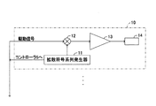
以下、本発明の実施形態を図面を用いて説明する。図1は、本発明に係り、生体内部、例えば、被検体としての眼底の診察に利用される光干渉断層計Hの構成を概略的に示している。図1に示すように、光干渉断層計Hは、光出射部1と、光干渉部2と、光検出部3と、表示部4とを備えている。また、光干渉断層計Hは、CPU、ROM、RAMなどからなるマイクロコンピュータを主要構成部品とするコントローラ5を備えている。
Hereinafter, embodiments of the present invention will be described with reference to the drawings. FIG. 1 relates to the present invention and schematically shows the configuration of an optical coherence tomography H used for diagnosis of the inside of a living body, for example, a fundus as a subject. As shown in FIG. 1, the optical coherence tomometer H includes a
光出射部1は、異なる特定波長を有する光をスペクトラム拡散変調して発生する複数の光発生器10から構成されている。なお、本実施形態においては、図1に示すように、光出射部1を2つの光発生器10から構成して、言い換えれば、光出射部1から2つの特定波長を有する光を発生するように構成して実施する。しかしながら、光出射部1を構成する光発生器10の数すなわち出射する光の特定波長の数については、限定されるものではなく、光出射部1を3つ以上の光発生器10から構成して実施可能であることはいうまでもない。このように、必要に応じて光発生器10を多数設けることにより、後述する生体情報としての酸素飽和度の算出において定量性が十分に確保できる。
The
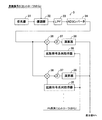
各光発生器10は、図2に示すように、拡散符号系列発生器11、掛け算器12、光源ドライバ13および光源14を備えている。拡散符号系列としての拡散符号系列発生器11は、例えば、128ビット長の「+1」と「−1」からなるPN(Pseudorandom Noise)系列を発生させるものである。そして、この拡散符号系列発生器11は、例えば、アダマール系列やM系列、あるいは、ゴールド符号系列をPN系列として発生する。
As shown in FIG. 2, each
なお、上述したアダマール系列、M系列、あるいは、ゴールド符号系列は、一般的にスペクトラム拡散変調に用いられるものと同様であるため、その発生方法に関する詳細な説明は省略するが、以下に簡単に説明しておく。アダマール系列は、「+1」と「−1」からなるアダマール行列の各行または各列を取り出して得られる系列である。M系列は、「0」または「+1」の状態を記憶する1ビットのレジスタをn段並べたシフトレジスタを用い、同シフトレジスタの中間から帰還した値と最終段における値との排他的論理和を初段に接続することにより得られる2値系列である。ただし、この2値系列をPN系列とするために、レベル変換を行い、値「0」を「−1」に変換する。ゴールド符号系列は、基本的には、2種類のM系列を用意し、これらを加算して得られる符号系列である。このため、ゴールド符号系列は、M系列に比して、格段に系列数を増やすことができる系列である。そして、これらの系列の特徴として、異なる系列は互いに直交する性質を有しており、積和演算を行うことによって「0」、すなわち、自己以外には相関が「0」となることが挙げられる。 The Hadamard sequence, the M sequence, or the Gold code sequence described above is the same as that generally used for spread spectrum modulation, and thus a detailed description of the generation method is omitted, but a brief description is given below. Keep it. The Hadamard sequence is a sequence obtained by extracting each row or each column of the Hadamard matrix composed of “+1” and “−1”. The M series uses a shift register in which n stages of 1-bit registers for storing a state of “0” or “+1” are arranged, and an exclusive OR of a value fed back from the middle of the shift register and a value in the last stage Is a binary sequence obtained by connecting to the first stage. However, in order to make this binary sequence a PN sequence, level conversion is performed to convert the value “0” into “−1”. The Gold code sequence is basically a code sequence obtained by preparing two types of M sequences and adding them. For this reason, the Gold code sequence is a sequence that can significantly increase the number of sequences as compared to the M sequence. As a feature of these sequences, different sequences have the property of being orthogonal to each other, and by performing a product-sum operation, “0”, that is, the correlation becomes “0” except for self. .
このように、拡散符号系列発生器11の発生したPN系列は、コントローラ5に出力されるとともに、掛け算器12に出力される。掛け算器12は、コントローラ5から供給される駆動信号と、拡散符号系列発生器11から供給されるPN系列との積を取る。これにより、駆動信号をスペクトラム拡散変調することができる。そして、掛け算器12は、スペクトラム拡散変調した駆動信号すなわち変調駆動信号を光源ドライバ13に供給する。なお、掛け算器12は、本発明のスペクトラム拡散変調手段を構成する。
In this way, the PN sequence generated by the spread
光源ドライバ13は、掛け算器12から供給された変調駆動信号に基づいて、光源14を駆動(発光)させるものである。光源14は、例えば、レーザダイオード(Laser Diode:LD)やスーパールミネッセンスダイオード(Super Luminescence Diode:SLD)などの近赤外発光素子から構成されている。これにより、光源14は、特定波長を有する近赤外線可干渉光を発光する。ここで、光源14の発光する近赤外線可干渉光の特定波長としては、例えば、600nm〜900nm程度の特定波長から選択されるとよく、以下の説明においては、2つの光源14のうち、一方の光源14は、例えば、780nmの特定波長を有する近赤外線可干渉光を発光し、他方の光源14は、例えば、830nmの特定波長を有する近赤外線可干渉光を発光するものとして説明する。そして、各光源14によって発光された近赤外線可干渉光は、図1に示すように、集光レンズによって集光された後、ハーフミラーにより同一光軸上に出射される。
The
光干渉部2は、近赤外線可干渉光を光学的に2方向に分離するとともに、同分離した近赤外線可干渉光の反射光を互いに干渉させるものである。このため、光干渉部2は、図1に示すように、ビームスプリッタ21と、光波長シフター22と、コリメートレンズ23と、可動ミラー24と、ミラー移動機構25とから構成されている。
The optical interference unit 2 optically separates near-infrared coherent light in two directions and causes reflected light of the separated near-infrared coherent light to interfere with each other. Therefore, as shown in FIG. 1, the optical interference unit 2 includes a
ビームスプリッタ21は、図3に示すように、例えば、硼珪酸ガラス(商品名:BK7)や溶融石英ガラス(商品名:コルツ)など透明かつ低屈折率の材料から形成される基板21aを備えている。なお、基板21aの板厚としては、例えば、0.3mm程度が好ましい。そして、この基板21aの一面側、より詳しくは、眼底に対向する側には、反射層として、所定の層厚(例えば、0.1μm程度)を有するアルミ蒸着層21bが形成されている。このアルミ蒸着層21b上には、同層21bの酸化を防止するための保護層21cが層状に形成されている。なお、保護層21cとしては、例えば、SiO2,SiOやAlO3などを採用するとよい。
As shown in FIG. 3, the
そして、ビームスプリッタ21を形成するアルミ蒸着層21bと保護層21cとには、これら各層21b,21cの形成面方向の略中央部分に層の形成されていない部分、すなわち、孔部21d(以下、この孔部を透過孔21dという)が設けられている。なお、透過孔21dは、例えば、アルミ蒸着層21bと保護層21cを形成する際に対応部分をマスクで覆って蒸着する方法、または、アルミ蒸着層21bおよび保護層21cを形成した後にエッチングする方法によって形成されるとよい。
And in the aluminum
この透過孔21dは、光干渉断層計Hにおけるビームスプリッタ21の配置状態、詳しくは、光出射部1から出射される近赤外線可干渉光の光軸に対して45°傾斜して配置された状態において、所定の孔径を有する円形となるように形成されている。ここで、所定の孔径としては、特に限定されるものではないが、好ましくは、光出射部1から出射される近赤外線可干渉光の光束と同程度以上に設定されるとよい。また、透過孔21dの形状についても、特に限定されるものではなく、真円以外に、例えば、長穴や角孔などを採用することが可能である。なお、この透過孔21dの形成された部分に対応する基板21aの領域が本発明の低反射領域を形成する。
This
また、基板21aの他面側、詳しくは、光源14に対向する側には、反射抑制層21eが形成されている。この反射抑制層21eは、ビームスプリッタ21に入射した近赤外線可干渉光が、基板21aにおける光源14側の表面で反射されて波長シフター22方向へ伝播することを防止する一方で、基板21aにおける眼底側の内表面(すなわち、基板21aと空気との境界面)で反射されて波長シフター22方向へ伝搬することを許容するものである。ここで、反射抑制層21eは、例えば、フッ化マグネシウムなどを採用して形成するとよい。なお、本実施形態においては、ビームスプリッタ21の形状を図3に示したように、円形として実施するが、その他の形状、例えば、角型を採用して実施可能であることはいうまでもない。
Further, a
光波長シフター22は、音響光学変調器(Acousto-Optic Modulator:AOM)などを主要構成部品とし、ビームスプリッタ21によって反射されて入射した近赤外線可干渉光の周波数を僅かに変化させるものである。なお、光波長シフター22は、近赤外線可干渉光の周波数を変化させることから、光周波数シフターと称する場合もある。この光波長シフター22は、偏向媒体22aと圧電変換素子22bとから構成されている。偏向媒体22aは、例えば、二酸化テルル(TeO2)など無色透明の単結晶から形成されるものである。圧電変換素子22bは、コントローラ5から図示省略の1/2回路を介して供給される所定の発振信号Sに基づいて駆動制御されて、例えば、10〜100(MHz)程度の周波数を有する超音波を偏向媒体22aに対して入射するものである。なお、圧電変換素子22bとしては、例えば、ピエゾ素子などを採用することができる。
The
このように構成される光波長シフター22においては、圧電変換素子22bの発振によって入射された超音波の疎密波に起因して、偏向媒体22a中に屈折率の周期的な変化が生じる。これにより、偏向媒体22aを通過する近赤外線可干渉光の周波数は、超音波の周波数分だけ増加(または減少)するとともに、近赤外線可干渉光の波長(より詳しくは波数)に応じて所定方向に屈折される。そして、光波長シフター22によって周波数が変化した近赤外線可干渉光は、コリメートレンズ23によって平行な光束に整えられた後、可動ミラー24に到達する。
In the
可動ミラー24は、図1に示すように、その反射面がコリメートレンズ23によって整えられた近赤外線可干渉光の光軸に対して直交するように配置されている。この配置により、可動ミラー24は、到達した近赤外線可干渉光を、再びコリメートレンズ23を介して光波長シフター22に向けて反射する。ここで、コリメートレンズ23は、図1にて破線で示すように、ビームスプリッタ21によって反射された近赤外線可干渉光の光軸上であり、かつ、光波長シフター22上に、仮想的な焦点Eを有するように配置されている。これにより、可動ミラー24によって反射された近赤外線可干渉光は、コリメートレンズ23により、ビームスプリッタ21によって反射された近赤外線可干渉光の光軸上に集光されるようになっている。ミラー移動機構25は、例えば、ピエゾ素子を主要構成部品とするアクチュエータである。そして、ミラー移動機構25は、コントローラ5によって作動制御されて、可動ミラー24をコリメートレンズ23によって整えられた近赤外線可干渉光の光軸方向に移動させるようになっている。
As shown in FIG. 1, the
次に、このように構成された光干渉部2の動作について説明する。光出射部1から出射された近赤外線可干渉光は、ビームスプリッタ21に到達する。そして、ビームスプリッタ21は、到達した近赤外線可干渉光の大部分を眼底に向けて透過するとともに同光の一部を光波長シフター22に向けて反射して、入射した近赤外線可干渉光を2方向に分離する。具体的に説明すると、光源14から出射された近赤外線可干渉光は、反射抑制層21eを透過して基板21aまで到達する。そして、近赤外線可干渉光が基板21a内に入射すると、上述したように形成された透過孔21dにより、近赤外線可干渉光の大部分(約96%程度)が反射されることなく、眼底方向へ通過する。
Next, the operation of the optical interference unit 2 configured as described above will be described. Near-infrared coherent light emitted from the
ところで、近赤外線可干渉光が基板21a内に入射すると、眼底側の内表面(すなわち、基板21aと空気の境界面)で反射が生じる。このため、近赤外線可干渉光が基板21a内を通過する際には、その一部(約4%程度)が反射され、この反射した近赤外線可干渉光が光波長シフター22に向けて伝搬する。なお、ビームスプリッタ21を通過した近赤外線可干渉光は、例えば、光ファイバーなどを介して、眼底方向に伝搬する。また、ビームスプリッタ21によって反射された近赤外線可干渉光も、例えば、光ファイバーなどを介して、光波長シフター22方向に伝搬する。
By the way, when near-infrared coherent light enters the
ビームスプリッタ21を通過した近赤外線可干渉光は、光ファイバーを介して、偏光板Bに出射される。ここで、偏光板Bは、光源14から出射される近赤外線可干渉光の偏光面と一致するように、その直線偏光方向が調整されている。これにより、ビームスプリッタ21を通過した近赤外線可干渉光は、そのまま偏光板Bを通過する。このように、偏光板Bを通過した近赤外線可干渉光は、対物レンズRにより集光されて眼底に到達する。なお、この場合、偏光板Bを通過した近赤外線可干渉光の光軸を、例えば、図示しない2軸のカルバノミラーなどを用いて適宜変更し、対物レンズRによって集光された焦点が眼底の表面上を走査できるようにするとよい。
The near-infrared coherent light that has passed through the
そして、対物レンズRによって集光された近赤外線可干渉光は、一点鎖線で示すように、眼底の表面近傍で反射される。なお、以下の説明においては、眼底の表面近傍で反射された反射光を計測光という。計測光は、眼底の表面近傍で反射されることによって、大きく散乱された状態となっている。言い換えれば、計測光の光束は、十分大きく拡げられた状態となっている。このように光束が大きく拡げられた計測光は、再び、対物レンズRを通過することにより、平行な光束に整えられ、偏光板Bを通過する。このとき、偏光板Bの直線偏光方向は、光源14から出射される近赤外線可干渉光の偏光面と同一であるため、偏光板Bを通過した計測光の偏光面は、ビームスプリッタ21を通過した近赤外線可干渉光の偏光面と同一となる。そして、偏光板Bを通過した計測光がビームスプリッタ21に到達すると、アルミ蒸着層21bによって反射される。このとき、計測光の光束が大きく拡げられているため、ビームスプリッタ21に到達した計測光の大部分は、その伝搬方向が90°だけすなわち図1に示す光検出部3方向に変更される。
The near-infrared coherent light collected by the objective lens R is reflected near the surface of the fundus as indicated by the alternate long and short dash line. In the following description, the reflected light reflected near the surface of the fundus is referred to as measurement light. The measurement light is largely scattered by being reflected near the surface of the fundus. In other words, the luminous flux of the measurement light is in a sufficiently widened state. The measurement light whose light beam is greatly expanded in this way is again adjusted to a parallel light beam by passing through the objective lens R and passes through the polarizing plate B. At this time, since the linear polarization direction of the polarizing plate B is the same as the polarization plane of the near-infrared coherent light emitted from the
なお、透過孔21dおよび基板21aを通過する計測光は、透過孔21dの開口面積がアルミ蒸着層21bによる反射面積に比して小さいため、透過孔21dおよび基板21aを通過する計測光の光量は僅かである。したがって、計測光が透過孔21dおよび基板21aを通過することによる計測精度に与える影響は、極めて小さい。
Since the measurement light passing through the
一方、ビームスプリッタ21によって分離されて光波長シフター22方向に伝搬する近赤外線可干渉光は、図示省略の光ファイバーを介して、光波長シフター22に到達する。光波長シフター22においては、圧電変換素子22bがコントローラ5から供給された発振信号Sに基づいて周波数RFで発振しており、この発振に伴い偏向媒体22a中の屈折率が周波数RFで周期的に変化している。ここで、近赤外線可干渉光が周波数fを有して光波長シフター22の偏向媒体22aに入射すると、周期的に変化する屈折率に基づくドップラー効果を受けて、近赤外線可干渉光の周波数がf+RF(または、f−RF)に変化する。さらに、偏向媒体22a中においては、屈折率が周期的に変化しているために屈折率の勾配が存在する。このように屈折率の勾配が存在することによって、偏向媒体22aに入射した近赤外線可干渉光は、同光の波長に依存して決まる方向に屈折する。そして、周波数がf+RF(または、f−RF)に変化するとともに屈折した近赤外線可干渉光は、コリメートレンズ23方向に出射される。コリメートレンズ23においては、光波長シフター22から出射された近赤外線可干渉光を平行な光束となるように整え、可動ミラー24の反射面に対して垂直に出射する。
On the other hand, near-infrared coherent light that is separated by the
可動ミラー24に到達した近赤外線可干渉光は、同一光軸上にて反射されて、再び、コリメートレンズ23に入射する。このとき、コリメートレンズ23は、入射した近赤外線可干渉光を光波長シフター22上に形成する仮想的な焦点Eに集光する。そして、コリメートレンズ23によって集光されて光波長シフター22の偏向媒体22a内に入射した近赤外線可干渉光は、再び、ドップラー効果を受けて、その周波数がf+2・RF(または、f−2・RF)に変化する。また、仮想的な焦点Eはビームスプリッタ21によって反射された近赤外線可干渉光の光軸上に形成されるため、周波数がf+2・RF(または、f−2・RF)に変化した近赤外線可干渉光は、上述した屈折率の勾配によって偏向した後、同一の光軸上を進み、再び、光ファイバーを介して、ビームスプリッタ21に到達する。
Near-infrared coherent light that has reached the
ここで、光波長シフター22による近赤外線可干渉光の周波数の変化すなわち「±2・RF」は、上述したように、圧電変換素子22bが発振するMHzオーダーの変化である。この変化は、近赤外線可干渉光の有する周波数f(THz)に比して極めて小さいものである。このため、光波長シフター22によって周波数すなわち波長が変化した近赤外線可干渉光であっても、偏向媒体22a中においては、屈折率の勾配によってほぼ同一方向に屈折して偏向する。したがって、光波長シフター22からビームスプリッタ21に向けて伝搬する近赤外線可干渉光の光軸とビームスプリッタ21によって反射された近赤外線可干渉光の光軸とは、同一の光軸であるとみなしても問題ない。
Here, the change in the frequency of near-infrared coherent light by the
このように、光波長シフター22からビームスプリッタ21に伝搬した近赤外線可干渉光(以下の説明においては、この近赤外線可干渉光を参照光という)は、上述した眼底への近赤外線可干渉光の通過と同様に、その大部分(約96%)が基板21aおよび透過孔21dを通過して光検出部3の方向に伝搬する。なお、参照光の一部(約4%)は、基板21aを透過することによって光出射部1の方向に反射されるが、その光量は僅かであるため、計測精度に対する影響は極めて小さい。
As described above, the near-infrared coherent light propagated from the
ここで、参照光の偏光面は、光出射部1から出射された状態を維持している。このため、ビームスプリッタ21によって反射されて光検出部3の方向に伝搬する計測光の偏光面と、ビームスプリッタ21を透過して光検出部3方向に伝搬する参照光の偏光面とは同一である。これにより、これら計測光と参照光は互いに干渉することができる。なお、以下の説明においては、計測光と参照光とが干渉した近赤外線可干渉光を干渉光という。そして、この干渉光は、図示省略の光ファイバーなどを介して伝搬し、集光レンズSRにより集光された後、光検出部3によって検出される。
Here, the polarization plane of the reference light maintains the state of being emitted from the
光検出部3は、光干渉部2からの干渉光を検出し、同検出した干渉光に対応する検出信号を用いて眼底の断面形状を表す情報や生体情報としての血中の酸素飽和度を表す情報を出力するものである。このため、光検出部3は、図4に示すように、受光器31と、復調器32と、ローパスフィルタ33(以下、LPF33という)と、ADコンバータ34とを備えている。
The
受光器31は、例えば、フォトディテクタ(photo detector)やフォトダイオード(photo diode)などの光電変換素子を主要構成部品とするものであり、光干渉部2からの干渉光を受光すると、同干渉光の強度を表す電気的な検出信号を時系列的に復調器32に出力する。復調器32は、受光器31から出力された電気的な検出信号を、コントローラ5から供給される発振信号Sを用いて復調するものである。LPF33は、復調器32によって復調された電気的な検出信号のうちの高周波成分を除去するものである。ADコンバータ34は、LPF33によってフィルタリングされた電気的な検出信号(アナログ信号)をデジタル信号に変換するものである。
The
ここで、受光器31、復調器32およびLPF33によって処理されて出力される検出信号について説明しておく。今、参照光と計測光の電界成分をそれぞれEr,Esとすると、電界成分Er,Esは下記式1,2で示すことができる。
Er=ar・cos(2π・fr+θr) …式1
Es=as・cos(2π・fs+θs) …式2
ただし、前記式1中のarは参照光の振幅を表し、frは参照光の周波数すなわち上述した周波数(f+2・RF)を表し、θrは参照光の位相を表すものである。また、前記式2中のasは計測光の振幅を表し、fsは計測光の周波数すなわち上述した周波数fを表し、θsは計測光の位相を表すものである。
Here, the detection signal processed and output by the
Er = ar · cos (2π · fr + θr) ...
Es = as · cos (2π · fs + θs) ... Formula 2
However, ar in
したがって、受光器31によって受光される干渉光の光強度を表す検出信号Iは、下記式3で示すことができる。
I=|Er+Es|2 …式3
前記式3に対して、前記式1,2を代入して整理すると、下記式4が成立する。
I=(ar2+as2)/2+ar・as・cos(2π・(fr−fs)+(θr−θs)) …式4
ここで、以下の説明においては、計測光と参照光とが互いに干渉する場合すなわち計測光に眼底の状態を表す情報が付加された場合について説明する。なお、計測光と参照光とが互いに干渉していなければ、前記式4に従って検出信号Iは下記式5によって示すことができる。
I=(ar2+as2)/2 …式5
Therefore, the detection signal I indicating the light intensity of the interference light received by the
I = | Er + Es | 2
By substituting the
I = (ar 2 + as 2 ) / 2 + ar · as · cos (2π · (fr−fs) + (θr−θs)) Equation 4
Here, in the following description, a case where the measurement light and the reference light interfere with each other, that is, a case where information indicating the state of the fundus is added to the measurement light will be described. If the measurement light and the reference light do not interfere with each other, the detection signal I can be expressed by the following
I = (ar 2 + as 2 ) / 2
受光器31から前記式4によって示される電気的な検出信号Iが出力されると、復調器32は供給された電気的な検出信号Iを復調する。このことを以下に具体的に説明する。まず、復調器32は、コントローラ5から下記式6に示す発振信号Sを取得する。
S=arf・cos(2π・(2・RF)+θrf) …式6
ただし、前記式6中のarfは上述した圧電変換素子22bの発振振幅を表し、RFは発振周波数を表し、θrfは発振の位相を表すものである。
When the electrical detection signal I represented by the above equation 4 is output from the
S = arf · cos (2π · (2 · RF) + θrf) ... Formula 6
In Equation 6, arf represents the oscillation amplitude of the
そして、復調器32は、受光器31から出力された電気的な検出信号Iを復調するために、下記式7に示すように、検出信号Iに対して発振信号Sを乗算し、復調した電気的な検出信号Imを計算する。
Im=I・S=((ar2+as2)/2+ar・as・cos(2π・(fr−fs)+(θr−θs)))・arf・cos(2π・(2・RF)+θrf) …式7
前記式7を整理すると、下記式8が成立する。
Im=((ar2+as2)/2)・arf・cos(2π・(2・RF)+θrf)+ar・as・arf・(1/2)・(cos(2π・(fr−fs)+θr−θs−2π・(2・RF)−θrf)+cos(2π・(fr−fs)+θr−θs+2π・(2・RF)+θrf)) …式8
ここで、下記式9が成立することを考慮すると、電気的な検出信号Imは下記式10のように示すことができる。
fr−fs=2・RF …式9
Im=((ar2+as2)/2)・arf・cos(2π・(2・RF)+θrf)+ar・as・arf・(1/2)・cos(θr−θs−θrf)+ar・as・arf・(1/2)・cos(2・2π・(2・RF)+θr−θs+θrf)) …式10
Then, in order to demodulate the electrical detection signal I output from the
Im = I · S = ((ar 2 + as 2 ) / 2 + ar · as · cos (2π · (fr−fs) + (θr−θs))) · arf · cos (2π · (2 · RF) + θrf)… Equation 7
By rearranging the formula 7, the following formula 8 is established.
Im = ((ar 2 + as 2 ) / 2) ・ arf ・ cos (2π ・ (2 ・ RF) + θrf) + ar ・ as ・ arf ・ (1/2) ・ (cos (2π ・ (fr−fs) + θr− θs−2π · (2 · RF) −θrf) + cos (2π · (fr−fs) + θr−θs + 2π · (2 · RF) + θrf))
Here, considering that the following formula 9 holds, the electrical detection signal Im can be expressed as the following
fr−fs = 2 · RF Equation 9
Im = ((ar 2 + as 2 ) / 2) · arf · cos (2π · (2 · RF) + θrf) + ar · as · arf · (1/2) · cos (θr−θs−θrf) + ar · as · arf · (1/2) · cos (2 · 2π · (2 · RF) + θr−θs + θrf))
前記式10に示した電気的な検出信号Imは、LPF33に出力される。LPF33は、例えば、(fr−fs)で表される周波数すなわち2・RF以上の高周波成分を除去する。以下、このフィルタ処理を説明する。前記式9に示したように、参照光の周波数frと計測光の周波数fsとの差すなわち2・RFは、所謂、光ビート周波数を表している。そして、この光ビート周波数を含む前記式6で示した発振信号Sを乗算し、前記式4で示した検出信号Iを復調することによって、前記式10に示した電気的な検出信号Imを得ることができる。
The electrical detection signal Im shown in
ところで、前記式10に示した電気的な検出信号Imは、光ビート周波数を含む交流成分項と光ビート周波数を含まない直流成分項とから形成されている。この場合、高周波成分としての交流成分項は、眼底の計測において、所謂、ノイズとして影響するため、正確に眼底を計測するためにはこの交流成分項を除去する必要がある。このため、LPF33は、電気的な検出信号Imを、光ビート周波数2・RFを用いてローパスフィルタ処理し、高周波成分としての交流成分項を除去する。このように、LPF33がフィルタ処理することによって、下記式11に示すように、眼底の計測に必要な検出信号Imの直流成分項としての検出信号Ijを得ることができる。
Ij=ar・as・arf・(1/2)・cos(θr−θs−θrf) …式11
By the way, the electrical detection signal Im shown in the
Ij = ar · as · arf · (1/2) · cos (θr−θs−θrf)
そして、前記式11に従って検出信号Ijが得られることにより、所謂、光ヘテロダイン効果によって、眼底における散乱に起因して微弱となった計測光の振幅asを増幅することができる。すなわち、前記式11に従って計算される検出信号Ijは、眼底の状態を表す計測光の振幅asが小さくても、容易に調整可能な参照光の振幅arと圧電変換素子22bの発振振幅arfによって大幅に増幅できることを表している。したがって、眼底の計測によって得られる電気的な検出信号IjのS/N比を大幅に改善することができて、計測の精度を大幅に高めることが可能となる。具体的に説明すると、例えば、光波長シフター22を設けない場合、言い換えれば、光ビート周波数を有する発振信号Sで電気的な検出信号Iを復調しない場合には、計測光の周波数fsと参照光の周波数frとが同一であるため、前記式4に従って、電気的な検出信号Iは下記式12のようになる。
I=(ar2+as2)/2+ar・as・cos(θr−θs) …式12
Then, by obtaining the detection signal Ij according to the
I = (ar 2 + as 2 ) / 2 + ar · as · cos (θr−θs)
この式12と前記式11とを比較すると、前記式12においては、右辺第1項に(ar2+as2)/2が存在する。したがって、例えば、右辺第2項における微弱な計測光の振幅asを増幅するために参照光の振幅arを大きくした場合には、右辺第2項の値の変化に比して右辺第1項の値が極めて大きく変化する。すなわち、この場合には、参照光の振幅arを大きくすることによって、眼底の計測に不必要な右辺第1項がノイズとして大きく影響するようになる。このため、参照光の振幅arを大きくして計測光の振幅asを増幅しても、右辺第2項によって示される干渉光の光強度が相対的に小さくなり、電気的な検出信号IのS/N比を改善することができない。これに対して、前記式11によれば、参照光の振幅ar(または、発振振幅arf)を大きくすることによって計測光の振幅asを増幅して、計測に必要な干渉光の光強度を大きくすることができる。したがって、電気的な検出信号IjのS/N比を大幅に改善することができ、この結果、後述するように、眼底の状態を極めて正確に観察することができる。
Comparing
また、光検出部3は、拡散符号系列取得器35と、掛け算器36と、累算器37と、演算器38とを備えている。拡散符号系列取得器35は、コントローラ5から、受光すべき特定の光発生器10からの近赤外線可干渉光が有する拡散符号系列すなわちPN系列を取得する。そして、拡散符号系列取得器35は、取得したPN系列をそれぞれの掛け算器36に供給する。
The
掛け算器36は、ADコンバータ34によってデジタル信号とされた検出信号Ijと、拡散符号系列取得器35から供給されたPN系列との積を取る。そして、掛け算器36は、計算した検出信号IjとPN系列との積の値を累算器37に出力する。累算器37は、供給された積の値を、前記供給されたPN系列の1周期以上に渡り加算する。そして、累算器37は、特定の光発生器10から出射されて眼底にて反射した計測光を含む干渉光に対応する検出信号Ijを演算器38に供給する。
The
演算器38は、累算器37によって出力された検出信号Ijに基づいて、干渉光の光強度すなわち光量分布を用いて眼底部分における断面形状を表す断面形状信号を算出する。なお、断面形状信号の算出については、具体的に後述する。また、演算器38は、特定の光発生器10から出射される光量と受光した干渉光の光量とを用いて、眼底部分における毛細血管中を流れる血液の酸素飽和度SO2を算出する。ここで、演算器38による血液の酸素飽和度SO2の算出について説明しておく。血液中のヘモグロビン、より詳しくは、酸素と結合した酸素化ヘモグロビンと酸素と結合していない還元ヘモグロビンにおける近赤外光の吸光特性は、文献(例えば、株式会社日立メディコ、MEDIX,vol.29など)に示されて一般的に知られるように、ランバート・ベール(Lambert-Beer)の法則に従って、下記式13のように示すことができる。
−ln(R(λ)/Ro(λ))=εoxy(λ)・Coxy・d+εdeoxy(λ)・Cdeoxy・d+α(λ)+S(λ) …式13
Based on the detection signal Ij output from the
−ln (R (λ) / Ro (λ)) = εoxy (λ) · Coxy · d + εdeoxy (λ) · Cdeoxy · d + α (λ) + S (λ)
ただし、前記式13中のR(λ)、Ro(λ)およびdは、図5に概略的に示すように、それぞれ、波長λの干渉光の検出光量、波長λの近赤外線可干渉光の出射光量および検出領域の光路長を表すものである。また、前記式13中のεoxy(λ)は、波長λに対する酸素化ヘモグロビンの分子吸光係数を表し、εdeoxy(λ)は、波長λに対する還元ヘモグロビンの分子吸光係数を表すものである。また、前記式13中のCoxyは、酸素化ヘモグロビンの濃度を表し、Cdeoxyは、還元ヘモグロビンの濃度を表すものである。さらに、前記式13中のα(λ)は、血液中のヘモグロビン以外の色素(例えば、細胞中のミトコンドリアでの酸素の需供を反映するチトクロームaa33など)の光吸収による減衰量を表し、S(λ)は、生体組織の光散乱による減衰量を表すものである。
However, R (λ), Ro (λ), and d in
このように、前記式13によって表される血液中のヘモグロビンの吸光特性に基づき、例えば、血管中の血流変化に着目して血流変化前後の差分を考慮することにより、血液中の酸素飽和度SO2を算出することができる。具体的に説明すると、眼底に存在する毛細血管について、血流変化前の吸光特性を前記式13に従って表せば、血流変化後の吸光特性は下記式14によって表すことができる。
−ln(growthR(λ)/Ro(λ))=εoxy(λ)・growthCoxy・d+εdeoxy(λ)・growthCdeoxy・d+growthα(λ)+S(λ) …式14
ただし、前記式14中のgrowthR(λ)、growthCoxy、growthCdeoxyおよびgrowthα(λ)は、血流変化によって増加または減少変化した値を表すものであって、それぞれ、血流変化後の検出光量、血流変化後の酸素化ヘモグロビンの濃度、血流変化後の還元ヘモグロビンの濃度および血流変化後のヘモグロビン以外の色素の光吸収による減衰量を表すものである。
Thus, based on the light absorption characteristics of hemoglobin in blood expressed by the
−ln (growthR (λ) / Ro (λ)) = εoxy (λ) · growthCoxy · d + εdeoxy (λ) · growthCdeoxy · d + growthα (λ) + S (λ)
However, growthR (λ), growthCoxy, growthCdeoxy, and growthα (λ) in the
ここで、血液中のヘモグロビンの光吸収量は、ヘモグロビン以外の色素の光吸収量に比して極めて大きいため、前記式13中のα(λ)をα(λ)=growthα(λ)とすることができる。これにより、前記式14から前記式13を差し引けば、下記式15が成立する。
−ln(growthR(λ)/R(λ))=εoxy(λ)・ΔCoxy+εdeoxy(λ)・ΔCdeoxy …式15
ここで、前記式15中のΔCoxyおよびΔCdeoxyは、それぞれ、下記式16および式17によって表されるものである。
ΔCoxy=(growthCoxy−Coxy)・d …式16
ΔCdeoxy=(growthCdeoxy−Cdeoxy)・d …式17
Here, since the light absorption amount of hemoglobin in the blood is extremely larger than the light absorption amount of a dye other than hemoglobin, α (λ) in the
−ln (growthR (λ) / R (λ)) = εoxy (λ) · ΔCoxy + εdeoxy (λ) · ΔCdeoxy Equation 15
Here, ΔCoxy and ΔCdeoxy in the formula 15 are represented by the following formulas 16 and 17, respectively.
ΔCoxy = (growthCoxy-Coxy) · d Equation 16
ΔCdeoxy = (growthCdeoxy−Cdeoxy) · d Equation 17
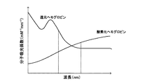
そして、図6にてヘモグロビンの光吸光スペクトルを概略的に示すように、吸光特性のコントラスト比が明確となる特定波長として、例えば、λ=780nmや830nmの近赤外線可干渉光を用いて計測した結果に基づいて、前記式15を解くことによって、酸素化ヘモグロビン濃度変化ΔCoxy、還元ヘモグロビン濃度変化ΔCdeoxyおよび全ヘモグロビン濃度変化(ΔCoxy+ΔCdeoxy)を相対的に計算することができる。そして、これらの各値を計算することによって、下記式18によって表される相対的な酸素飽和度SO2を計算することができる。
SO2=ΔCoxy/(ΔCoxy+ΔCdeoxy) …式18
このように、演算器38は、眼底の断面形状および酸素飽和度SO2を算出すると、同算出した断面形状を表す断面形状信号および酸素飽和度SO2を表す酸素飽和度信号を表示部4に出力する。
Then, as schematically showing the light absorption spectrum of hemoglobin in FIG. 6, measurement was performed using, for example, near-infrared coherent light with λ = 780 nm or 830 nm as a specific wavelength at which the contrast ratio of the light absorption characteristic becomes clear. Based on the result, by solving the equation 15, the oxygenated hemoglobin concentration change ΔCoxy, the reduced hemoglobin concentration change ΔCdeoxy and the total hemoglobin concentration change (ΔCoxy + ΔCdeoxy) can be relatively calculated. Then, by calculating these values, the relative oxygen saturation SO 2 represented by the following equation 18 can be calculated.
SO 2 = ΔCoxy / (ΔCoxy + ΔCdeoxy) Equation 18
Thus, the
ここで、上述した酸素化ヘモグロビン濃度変化ΔCoxy、還元ヘモグロビン濃度変化ΔCdeoxy、全ヘモグロビン濃度変化(ΔCoxy+ΔCdeoxy)および酸素飽和度SO2は、眼底内部に入射した近赤外線可干渉光が毛細血管中のヘモグロビンによって反射された計測光(干渉光)の検出光量を用いて計算されるものである。ところで、計測光(干渉光)の検出光量は、所定の計測深度における反射強度(屈折率変化など)を示しているが、計測光(干渉光)の吸収の影響は、同光の通過した光路全域におけるヘモグロビン濃度の影響を受けている。すなわち、例えば、眼底表面からの計測深度をDとすると、計測光(干渉光)の光量は、眼底表面から計測深度Dまでの吸収を往復で2回受けたものとなる。 Here, the oxygenated hemoglobin concentration change ΔCoxy, the reduced hemoglobin concentration change ΔCdeoxy, the total hemoglobin concentration change (ΔCoxy + ΔCdeoxy) and the oxygen saturation SO 2 are determined by the near-infrared coherent light incident on the inside of the fundus due to hemoglobin in the capillaries. It is calculated using the detected light quantity of the reflected measurement light (interference light). By the way, the detection light quantity of the measurement light (interference light) indicates the reflection intensity (refractive index change, etc.) at a predetermined measurement depth, but the influence of the absorption of the measurement light (interference light) is the optical path through which the light has passed. It is affected by hemoglobin concentration in the whole area. That is, for example, when the measurement depth from the fundus surface is D, the light amount of the measurement light (interference light) is obtained by reciprocating twice from the fundus surface to the measurement depth D.
したがって、計測光(干渉光)の眼底内部における吸収を考慮して酸素化ヘモグロビン濃度変化ΔCoxy、還元ヘモグロビン濃度変化ΔCdeoxy、全ヘモグロビン濃度変化(ΔCoxy+ΔCdeoxy)および酸素飽和度SO2を計算する場合には、所定の計測深度Dにおける計測光(干渉光)の光量と、所定の計測深度からの変化量ΔDにおける計測光(干渉光)の光量との比を求めるとよい。このとき、所定の計測深度Dにおける反射強度と変化量ΔDにおける反射強度とが略同一で、かつ、ヘモグロビンによる吸収減衰量が異なる波長の組み合わせ(例えば、780nmと830nmなど)となる近赤外線可干渉光について光量の比を求めるとよい。なお、これらの異なる波長の組み合わせにおいては、反射強度を決定している屈折率は、生体構成物質内にて、両波長の差が小さいため無視することができる。これにより、幅ΔD内での計測光(干渉光)の前記2波長における吸収減衰比を求めることができ、この吸収減衰比を用いて各ヘモグロビン濃度を計算することもできる。したがって、所定の計測深度Dのみにおける酸素化ヘモグロビン濃度変化ΔCoxy、還元ヘモグロビン濃度変化ΔCdeoxy、全ヘモグロビン濃度変化(ΔCoxy+ΔCdeoxy)および酸素飽和度SO2を算出することができる。 Therefore, when calculating the oxygenated hemoglobin concentration change ΔCoxy, the reduced hemoglobin concentration change ΔCdeoxy, the total hemoglobin concentration change (ΔCoxy + ΔCdeoxy) and the oxygen saturation SO 2 in consideration of the absorption of the measurement light (interference light) inside the fundus, A ratio between the light amount of the measurement light (interference light) at the predetermined measurement depth D and the light amount of the measurement light (interference light) at the change amount ΔD from the predetermined measurement depth may be obtained. At this time, near-infrared coherence is a combination of wavelengths (for example, 780 nm and 830 nm) in which the reflection intensity at the predetermined measurement depth D and the reflection intensity at the change amount ΔD are substantially the same and the absorption attenuation amount by hemoglobin is different. The ratio of the amount of light should be obtained. In addition, in the combination of these different wavelengths, the refractive index that determines the reflection intensity can be ignored because the difference between the two wavelengths is small in the living body constituent material. Thereby, the absorption attenuation ratio of the measurement light (interference light) within the width ΔD at the two wavelengths can be obtained, and each hemoglobin concentration can be calculated using this absorption attenuation ratio. Accordingly, it is possible to calculate the oxygenated hemoglobin concentration change ΔCoxy, the reduced hemoglobin concentration change ΔCdeoxy, the total hemoglobin concentration change (ΔCoxy + ΔCdeoxy) and the oxygen saturation SO 2 only at a predetermined measurement depth D.
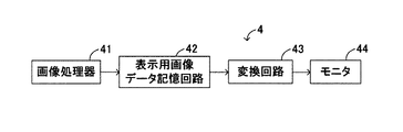
次に、表示部4を説明する。表示部4は、図7に示すように、画像処理器41と、表示用画像データ記憶回路42と、変換回路43と、モニタ44とを備えている。
Next, the display unit 4 will be described. As shown in FIG. 7, the display unit 4 includes an
画像処理器41は、図8に示すように、フレームコントロール回路41aと、フレームメモリ41bと、マルチプレクサ41cと、画像生成回路41dとを備えた回路である。フレームコントロール回路41aは、各フレームメモリ41bおよびマルチプレクサ41cの作動を制御する回路である。フレームメモリ41bは、フレームコントロール回路41aの制御に従って、光検出部3の演算器38によって出力された断面形状信号または酸素飽和度信号を、マルチプレクサ41cを介して画像生成回路41dに出力するものである。画像生成回路44dは、出力された断面形状信号または酸素飽和度信号に基づき、所定の態様でモニタ44に表示させる画像データを生成するものである。なお、この実施形態においては、演算器38から出力された信号をフレームメモリ41bに一時的に記憶するように実施するが、必要に応じて、前記各信号をマルチプレクサ41cに直接出力するように実施してもよい。
As shown in FIG. 8, the
表示用画像データ記憶回路42は、必要に応じて、画像データに対して付帯情報である数字や各種文字などのデータを付加して一旦保存する回路である。変換回路43は、表示用画像データ記憶回路42に保存された画像データに対して、例えば、D/A変換およびTVフォーマット変換などを行う回路である。
The display image
次に、上記のように構成した光干渉断層計Hの作動について、患者の眼底を観察する場合を例示して説明する。 Next, the operation of the optical coherence tomography H configured as described above will be described by exemplifying a case where the fundus of the patient is observed.
まず、医師またはオペレータは、光出射部1が照射する近赤外線可干渉光の光軸上に患者の眼球が位置するように、光干渉断層計Hを配置する。そして、医師またはオペレータは、コントローラ5の図示しない入力装置を操作して、近赤外線可干渉光の出射開始を指示する。これにより、コントローラ5は、光出射部1を構成する光発生器10のそれぞれに対して、同発生器10を駆動させるための駆動信号を供給する。これにより、2つの光発生器10は、同時にその作動を開始し、それぞれ、780nmの波長を有する近赤外線可干渉光と830nmの波長を有する近赤外線可干渉光を同時に出射する。
First, a doctor or an operator arranges the optical coherence tomometer H so that the patient's eyeball is positioned on the optical axis of the near-infrared coherent light irradiated by the
すなわち、各光発生器10においては、拡散符号系列発生器11が、例えば、PN系列としてゴールド符号系列を発生する。そして、拡散符号系列発生器11は、発生したPN系列をコントローラ5に対して出力するとともに、掛け算器12に出力する。掛け算器12は、コントローラ5から供給された駆動信号とPN系列との積を取り、駆動信号をスペクトラム拡散変調する。そして、スペクトラム拡散変調された変調駆動信号が光源ドライバ13に供給されることにより、光源ドライバ13は、光源14を発光させる。これにより、780nmの波長を有する近赤外線可干渉光と830nmの波長を有する近赤外線可干渉光とが同時に出射され、同出射された各近赤外線可干渉光は、集光レンズによって集光された後、ハーフミラーによって同一光軸上にて光学的に合成されて光干渉部2に向けて進む。
That is, in each
光学的に合成された近赤外線可干渉光は、光干渉部2に到達すると、ビームスプリッタ21によって光学的に2つに分離される。すなわち、近赤外線可干渉光は、その大部分が反射抑制層21e、基板21aおよび透過孔21dを透過するとともに偏光板Bおよび対物レンズRを通過して、患者の眼球に到達する。なお、以下の説明において、患者の眼球に到達する光を第1の近赤外線可干渉光という。また、ビームスプリッタ21に到達した近赤外線可干渉光の一部は、反射抑制層21eを透過後、基板21aの内表面で反射して、光波長シフター22に到達する。なお、以下の説明において、光波長シフター22に到達する近赤外線可干渉光を第2の近赤外線可干渉光という。
When the optically synthesized near-infrared coherent light reaches the optical interference unit 2, it is optically separated into two by the
眼球に入射した第1の近赤外線可干渉光は、眼底において散乱反射する。そして、反射した計測光は、光束が拡げられた状態で、対物レンズRによって平行な光束に整えられた後、偏光板Bによって直線偏光される。このとき、計測光の偏光面は、上述したように、第1の近赤外線可干渉光の偏光面と同一となる。そして、計測光は、ビームスプリッタ21に到達すると、大部分が光検出部3の方向へ反射される。一方、光波長シフター22に到達した第2の近赤外線可干渉光は、偏向媒体22aを透過することによって周波数が変化するとともに屈折し、コリメートレンズ23を介して可動ミラー24に到達する。そして、可動ミラー24に到達した第2の近赤外線可干渉光は、同ミラー24によって反射され、コリメートレンズ23を介して、再び、光波長シフター22に入射する。このように、第2の近赤外線可干渉光が光波長シフター22の偏向媒体22aに入射すると、再度、周波数が変化するとともに屈折し、参照光としてビームスプリッタ21に到達する。そして、参照光の大部分が光検出部3の方向へ透過する。このとき、参照光の偏光面は、上述したように、第2の近赤外線可干渉光の偏光面と同一の状態が維持されている。したがって、計測光と参照光との偏光面は、同一となる。
The first near-infrared coherent light incident on the eyeball is scattered and reflected on the fundus. The reflected measurement light is linearly polarized by the polarizing plate B after being adjusted to a parallel light beam by the objective lens R in a state where the light beam is expanded. At this time, the polarization plane of the measurement light is the same as the polarization plane of the first near-infrared coherent light as described above. When the measurement light reaches the
ここで、第2の近赤外線可干渉光は、780nmの波長を有する近赤外線可干渉光と830nmの波長を有する近赤外線可干渉光とが光学的に合成されたものである。このため、光波長シフター22の偏向媒体22a中における780nmの波長を有する近赤外線可干渉光と830nmの波長を有する近赤外線可干渉光の屈折率はそれぞれの波長差に依存して異なり、光波長シフター22から可動ミラー24へ出射する方向および光波長シフター22からビームスプリッタ21へ出射する方向が異なる。しかしながら、光波長シフター22と可動ミラー24との間にコリメートレンズ23を配置することによって、光波長シフター22から可動ミラー24へ出射する方向が異なっていても、それぞれの近赤外線可干渉光は常に平行な光束に整えられて可動ミラー24に到達し、同ミラー24への入射方向と同一の方向に反射される。また、光波長シフター22上に仮想的な焦点Eを形成するようにコリメートレンズ23を配置することにより、可動ミラー24によって反射されたそれぞれの近赤外線可干渉光は、常に、同一光軸上をビームスプリッタ21に向けて進む。したがって、コリメートレンズ23を光波長シフター22と可動ミラー24のと間に配置することによって、複数の近赤外線可干渉光から構成される参照光の進路に関する波長依存性を無くすことができる。
Here, the second near-infrared coherent light is optically synthesized from near-infrared coherent light having a wavelength of 780 nm and near-infrared coherent light having a wavelength of 830 nm. For this reason, the refractive indices of the near-infrared coherent light having a wavelength of 780 nm and the near-infrared coherent light having a wavelength of 830 nm in the deflecting medium 22a of the
そして、ビームスプリッタ21によって反射された計測光と、ビームスプリッタ21を透過した参照光とは、互いに干渉した状態で光検出部3に到達する。ここで、計測光と参照光とが互いに干渉する場合を説明しておく。今、ビームスプリッタ21と眼底との間の距離をL1とし、ビームスプリッタ21と可動ミラー24との間の距離をL2とする。このとき、距離L1と距離L2とが等しければ、計測光および参照光とが有するコヒーレント長(例えば、5μm〜20μm程度)だけ干渉する。これにより、光検出部3は、この干渉した近赤外線可干渉光すなわち干渉光を検出する。一方、距離L1と距離L2とが等しくなければ、計測光と参照光とが互いに干渉しない。これにより、光検出部3は干渉光を検出しない。
Then, the measurement light reflected by the
言い換えれば、ビームスプリッタ21から眼底までの距離L1がビームスプリッタ21から可動ミラー24までの距離L2に等しい場合には、眼底にて反射した計測光による干渉光が光検出部3によって良好に検出され、距離L1が距離L2と異なる場合には、干渉光が光検出部3によって検出されない。したがって、眼底の表面で反射したり、眼底の断面方向内部で反射したりして、距離L1によって決定される眼底の断面方向の位置と異なる位置からの計測光が光検出部3に到達している状況においては、これら計測光のうち、距離L2に等しい眼底の位置からの計測光のみが参照光との干渉光として検出される。
In other words, when the distance L1 from the
ところで、可動ミラー24は、ミラー移動機構25により、コリメートレンズ23によって平行な光束に整えられた第2の近赤外線可干渉光の光軸方向に移動することができるため、距離L2を任意に変更することができる。これにより、ミラー移動機構25を作動させて距離L2を任意に変更させることによって、光検出部3が検出可能な距離L1を順次変更することができる。したがって、距離L2を順次変更することによって、眼底の特定部位すなわち計測対象部位を順次変更することができ、同計測対象部位からの計測光を含む干渉光のみを選択的に分離して検出することができる。
By the way, the
光検出部3においては、受光器31が干渉光を検出する。このとき、受光器31には、780nmと830nmの波長を有する近赤外線可干渉光がともに干渉光として到達する。このような状況において、コントローラ5は、到達した干渉光のうち、特定の光発生器10から出射された近赤外線可干渉光に基づく計測光を含む干渉光を選択して受光するように、光検出部3を制御する。このコントローラ5による制御を具体的に説明する。
In the
コントローラ5は、上述したように、光出射部1に対して駆動信号を供給した後、各光発生器10からPN系列を取得する。そして、コントローラ5は、各光発生器10の拡散符号系列発生器11から取得したPN系列を、光検出部3に対して供給する。これにより、光検出部3は、供給されたPN系列を拡散符号系列取得器35によって取得する。そして、拡散符号系列取得器35は、取得したPN系列を掛け算器36に供給する。
As described above, the
一方、受光器31においては、干渉光をすべて受光し、同受光した干渉光に応じた電気的な検出信号Iを時系列的に復調器32に出力している。そして、復調器32は、コントローラ5から取得した発振信号Sを用いて、時系列的に出力された電気的な検出信号Iを復調し、復調した電気的な検出信号ImをLPF33に出力している。LPF33は、時系列的に出力された電気的な検出信号Imをフィルタ処理し、同フィルタ処理した電気的な検出信号IjをADコンバータ34に出力している。さらに、ADコンバータ34は、フィルタ処理された電気的な検出信号Ijをデジタル信号に変換するとともに同変換した電気的な検出信号Ijを掛け算器36に出力している。
On the other hand, the
この状態において、掛け算器36は、ADコンバータ34から出力されたデジタル変換された検出信号Ijと、拡散符号系列取得器35から供給されたPN系列との積を取る。そして、掛け算器36は計算した積の値を累算器37に出力し、累算器37は、出力された積の値をPN系列の1周期(すなわち、128ビット長)以上に渡り加算する。このように、掛け算器36と累算器37による積和処理により、検出信号IjとPN系列との相関を取ることができ、特定の光発生器10からの近赤外線可干渉光、具体的には、780nmまたは830nmの波長を有する計測光を含む干渉光に対応した検出信号Ijのみを選択して出力することができる。
In this state, the
すなわち、上述したように、PN系列に関しては、異なる系列が互いに直交する性質、言い換えれば、異なる系列同士の積の和が「0」となる性質を有している。このため、拡散符号系列取得器35が掛け算器36に対して、特定の光発生器10のPN系列を供給した場合には、ADコンバータ34から出力された検出信号Ijのうち、前記特定の光発生器10から出射された近赤外線可干渉光に対応する検出信号以外の検出信号と前記供給されたPN系列との積の和は「0」となる。これにより、累算器37によって加算される値も「0」となり、相関は「0」となる。したがって、拡散符号系列取得器35から供給されたPN系列を有しない(または一致しない)干渉光、言い換えれば、特定の光発生器10以外から出射された近赤外線可干渉光の計測光を含む干渉光は選択的に排除され、特定の光発生器10から出射された近赤外線可干渉光の計測光を含む干渉光に対応する検出信号Ijのみが演算器38に出力される。
That is, as described above, the PN sequence has a property that different sequences are orthogonal to each other, in other words, a property that the sum of products of different sequences is “0”. For this reason, when the spread code
演算器38においては、累算器37から供給された検出信号のうち、830nmの波長を有する計測光を含む干渉光に対応する検出信号Ijに基づき、生体情報として、眼底の断面形状を計算する。具体的に説明すると、上述したように、ミラー移動機構25を作動させることによって、可動ミラー24を移動させて距離L2を適宜変更することができる。そして、この距離L2の変更に伴い、距離L1も変更されることによって、眼底の表面から断面方向内部における計測対象部位を変更することができる。
The
このように、計測対象部位を変更した場合において、光検出部3の受光器31に到達する干渉光は眼底の断面方向におけるある反射面にて反射した計測光を含んでいるため、累算器37から演算器38に供給される検出信号Ijは、前記反射面における干渉光(計測光)の2次元的な光量分布を表している。このため、ビームスプリッタ21と可動ミラー24との間の距離L2を順次変化させる、すなわち、ビームスプリッタ21と眼底との間の距離L1を変化させて計測光の反射面を順次変化させることによって、演算器38は、各反射面における光量分布を得ることができる。ところで、この計測光の光量分布は、反射面の形状に応じて変化するものである。このため、これらの光量分布を断面方向にて重畳する合成計算を実行することにより、眼底の断面形状を計算することができる。そして、演算器38は、計算した眼底の断面形状を表す断面形状信号を表示部4の画像処理器41に出力する。
As described above, when the measurement target region is changed, the interference light reaching the
また、演算器38は、選択的に取得した780nmおよび830nmの計測光を含む干渉光に対応する検出信号Ijを用い、より詳しくは、上述した眼底の断面形状の計算と同様にある反射面における干渉光(計測光)の2次元的な光量分布を用い、前記式13〜18に従って酸素飽和度SO2を計算する。したがって、反射面が順次変更されることに伴って計算される酸素飽和度SO2を断面方向にて重畳する合成計算を実行することにより、眼底の断面形状の位置と一致した酸素飽和度SO2を計算することができる。そして、演算器38は、計算した酸素飽和度SO2を表す酸素飽和度信号を表示部4の画像処理器41に出力する。
Further, the
表示部4においては、画像処理器41のフレームコントロール回路41aが、光検出部3の演算部38から出力された断面形状信号および酸素飽和度信号をフレームメモリ41bに一時的に記憶させる。そして、フレームコントロール回路41aは、マルチプレクサ41cに対して、フレームメモリ41bの所定記憶位置に一時的に記憶されている断面形状信号および酸素飽和度信号を画像生成回路41dに出力させる。画像生成回路41dは、出力された断面形状信号に基づいて眼底の断面形状を表す断面形状画像データを生成するとともに、出力された酸素飽和度信号に基づいて断面形状の位置と一致する酸素飽和度SO2を表す酸素飽和度画像データを生成する。そして、画像生成回路41dは、生成した断面形状画像データおよび酸素飽和度画像データを表示用画像データ記憶回路42に出力する。
In the display unit 4, the
表示用画像データ記憶回路42においては、画像生成回路41dから供給された断面形状画像データおよび酸素飽和度画像データを一旦記憶する。そして、変換回路43によって、表示用画像データ記憶回路42に一旦記憶された画像データが変換されることにより、モニタ44は、眼底の断面形状や眼底の酸素飽和度をそれぞれ表示したり、合成された断面形状と酸素飽和度を表示する。
In the display image
以上の説明からも理解できるように、上記実施形態に係る光干渉断層計Hによれば、被検体としての眼球の眼底の断面形状を計測できるとともに、この断面形状に一致した部分の酸素飽和度SO2を計測することができる。これら断面形状および酸素飽和度SO2の計測においては、同時に波長の異なる近赤外線可干渉光を出射することにより、特に、酸素飽和度SO2の変化をより詳細に計測することができる。すなわち、酸素飽和度SO2の時間変化は比較的遅いものの、厳密には、時間変化している。これに対して、波長の異なる近赤外線可干渉光を同時に出射することにより、光検出部3に同一時点における眼底の状態、より詳しくは、酸素飽和度SO2の状態を反映した計測光が到達する。このため、ある瞬間における酸素飽和度SO2を良好に計測でき、時間経過に伴う酸素飽和度SO2の変化を極めて正確に算出することができる。また、上記実施形態に係る光干渉断層計Hによれば、計測に必要な計測光の光強度、より詳しくは、計測光の振幅を容易に増幅することができる。この結果、微弱な計測光に基づいて極めて正確な断面形状および酸素飽和度SO2を計測することができる。
As can be understood from the above description, according to the optical coherence tomography H according to the above-described embodiment, the cross-sectional shape of the fundus of the eyeball as the subject can be measured, and the oxygen saturation of the portion corresponding to the cross-sectional shape is measured. SO 2 can be measured. In the measurement of the cross-sectional shape and the oxygen saturation level SO 2 , the change in the oxygen saturation level SO 2 can be measured particularly in detail by emitting near-infrared coherent light having different wavelengths at the same time. That is, although the time change of the oxygen saturation SO 2 is relatively slow, strictly speaking, it changes with time. On the other hand, by simultaneously emitting near-infrared coherent light having different wavelengths, measurement light reflecting the state of the fundus at the same time point, more specifically the state of oxygen saturation SO 2 , arrives at the
上記実施形態においては、コントローラ5から供給された駆動信号をスペクトラム拡散変調した変調駆動信号に基づき、光出射部1の2つの光発生器10の発光タイミングを同時にして、近赤外線可干渉光を発光するように実施した。これに対して、光出射部1の2つの光発生器10の発光タイミングを所定の短い時間間隔で異ならせて、近赤外線可干渉光をパルス発光するように実施することも可能である。以下、この第1変形例について説明するが、上記実施形態と同一部分に同一の符号を付し、その詳細な説明を省略する。
In the above-described embodiment, near infrared coherent light is generated based on the modulation drive signal obtained by performing spread spectrum modulation on the drive signal supplied from the
この第1変形例における光干渉断層計Hの光出射部1においては、上記実施形態における光出射部1の光発生器10から拡散符号系列発生器11、掛け算器12が省略されて、図9に示すように、光源ドライバ13および光源14から構成される。この第1変形例における光源ドライバ13は、コントローラ5から取得した駆動信号に基づいて、光源14を駆動(発光)させるものである。また、光源14は、上記実施形態と同様に、例えば、レーザダイオード(Laser Diode:LD)やスーパールミネッセンスダイオード(Super Luminescence Diode:SLD)などの近赤外発光素子から構成される。このため、この第1変形例においても、各光源14から600nm〜900nm程度の波長範囲にある近赤外線可干渉光、具体的には、780nmの波長を有する近赤外線可干渉光と830nmの波長を有する近赤外線可干渉光が出射される。なお、この第1変形例においても、光発生器10の数については、2つに限定されるものではなく、3つ以上の光発生器10を設けて実施可能であることはいうまでもない。
In the
また、この第1変形例においては、光出射部1の変更に伴って、光検出部3も変更される。すなわち、この第1変形例における光検出部3においては、上記実施形態における光検出部3の拡散符号系列取得器35、掛け算器36および累算器37が省略されて、図10に示すように、受光器31、復調器32、LPF33、ADコンバータ34および演算器38から構成される。なお、この第1変形例における光検出部3においては、拡散符号系列取得器35、掛け算器36および累算器37が省略されること以外、上記実施形態と同様に干渉光を受光して眼底の断面形状信号および酸素飽和度信号を表示部4に出力する。このため、第1変形例における光検出部3の構成に関する説明は省略する。
In the first modification, the
次に、上記のように構成された第1変形例に係る光干渉断層計Hの作動について説明する。この第1変形例においても、医師またはオペレータは、光出射部1が照射する近赤外線可干渉光の光軸上に患者の眼球が位置するように、光干渉断層計Hを配置する。そして、医師またはオペレータは、コントローラ5の図示省略の入力装置を操作して、近赤外線可干渉光の出射開始を指示する。これにより、コントローラ5は、光出射部1を構成する2つの光発生器10のそれぞれに対して、所定の短い時間間隔で近赤外線可干渉光を発生させるための駆動信号を供給する。これにより、2つの光発生器10は、所定の短い時間間隔で、交互にその作動を開始する。
Next, the operation of the optical coherence tomometer H according to the first modification configured as described above will be described. Also in the first modified example, the doctor or the operator arranges the optical coherence tomometer H so that the patient's eyeball is positioned on the optical axis of the near-infrared coherent light irradiated by the
具体的に説明すると、780nmの波長を有する近赤外線可干渉光を発光する光発生器10においては、所定の短い時間間隔でコントローラ5から供給された駆動信号を光源ドライバ13によって取得する。これにより、光源ドライバ13は、取得した駆動信号に基づいて光源14をパルス発光させ、光源14は、780nmの波長を有する近赤外線可干渉光を、集光レンズを介してハーフミラーに向けて出射する。また、830nmの波長を有する近赤外線可干渉光を発光する光発生器10においても、所定の短い時間間隔でコントローラ5から供給された駆動信号を光源ドライバ13によって取得する。これにより、光源ドライバ13は、取得した駆動信号に基づいて光源14をパルス発光させ、光源14は、830nmの波長を有する近赤外線可干渉光を、集光レンズを介してハーフミラーに向けて出射する。このように、各光源14から出射された近赤外線可干渉光は、ハーフミラーを通過することによって同一の光軸上を光干渉部2に向けて進む。
More specifically, in the
光干渉部2においては、上記実施形態と同様に、ビームスプリッタ21によって、到達した近赤外線可干渉光が、第1の近赤外線可干渉光と第2の近赤外線可干渉光に光学的に分離される。そして、第1の近赤外線可干渉光は、ビームスプリッタ21を透過して患者の眼球に到達して眼底表面の近傍にて反射し、計測光として再びビームスプリッタ21に到達する。一方、第2の近赤外線可干渉光は、光波長シフター22を通過することによって周波数が変化するとともに可動ミラー24によって反射され、参照光として再びビームスプリッタ21に到達する。そして、計測光と参照光とが互いに干渉して、光検出部3に到達する。
In the optical interference unit 2, similarly to the above embodiment, the reached near-infrared coherent light is optically separated into the first near-infrared coherent light and the second near-infrared coherent light by the
光検出部3においては、上記実施形態と同様に、受光器31によって干渉光を受光し、同受光した干渉光の光強度に対応した電気的な検出信号Iが復調器32に出力される。復調器32においては、上記実施形態と同様に、発振信号Sを用いて電気的な検出信号Iを復調した検出信号ImをLPF33に出力する。LPF33は、光ビート周波数で検出信号Imをフィルタ処理して検出信号IjをADコンバータ34に出力し、ADコンバータ34は、検出信号Ijをデジタル信号に変換する。そして、演算器38は、上記実施形態と同様に、検出信号Ijを用いて患者の眼底の断面形状を表す断面形状信号を出力するとともに、前記式13〜式18に従って酸素飽和度SO2を計算して酸素飽和度信号を表示部4に出力する。これにより、表示部4が、上記実施形態と同様に、眼底の断面形状や眼底の酸素飽和度をそれぞれ表示したり、合成された断面形状と酸素飽和度を表示する。
In the
以上の説明からも理解できるように、この第1変形例に係る光干渉断層計Hにおいては、波長の異なる近赤外線可干渉光を順次発光することによって、眼底の断面形状および酸素飽和度SO2を計測することができる。これにより、生体内部における速い変化の計測においては、若干計測精度が劣るものの、光干渉断層計Hの構成を簡略化することができて、上記実施形態と同様の効果が期待できる。 As can be understood from the above description, in the optical coherence tomography H according to the first modification, the near-infrared coherent light having different wavelengths is sequentially emitted to thereby obtain the cross-sectional shape of the fundus and the oxygen saturation SO 2. Can be measured. Thereby, although the measurement accuracy is slightly inferior in the measurement of a fast change inside the living body, the configuration of the optical coherence tomography H can be simplified, and the same effect as the above embodiment can be expected.
なお、上記第1変形例においては、コントローラ5が、光出射部1を構成する2つの光発生器10のそれぞれに対して、所定の短い時間間隔で同発生器10を駆動させるための駆動信号を供給するように実施した。しかしながら、コントローラ5は、各光発生器10による近赤外線可干渉光の出射間隔を長くして、駆動信号を供給するように実施することも可能である。このように、近赤外線可干渉光の出射間隔を長く設定することによって、例えば、受光器31(フォトディテクタなど)の光検出速度を小さくすることができるため、光干渉断層計Hの製造コストを低減することができる。
In the first modified example, the
また、上記実施形態においては、透過孔21dの形成されたビームスプリッタ21を採用して実施した。これに対して、従来から広く知られて入射した近赤外線可干渉光を光学的に2つに分離するビームスプリッタを採用して実施することもできる。以下、この第2変形例について説明する。
Moreover, in the said embodiment, it implemented by employ | adopting the
この第2変形例に係る光干渉部2おいては、図11に示すように、ビームスプリッタ21に代えて、透過孔21dが形成されていないビームスプリッタ26が採用されている。このビームスプリッタ26は、光出射部1から出射された近赤外線可干渉光を、眼底方向と光波長シフター22の方向に対して、例えば、1:1に分離するものである。このため、眼底近傍で反射された計測光は、50%が光検出部3の方向に反射され、50%が光出射部1の方向に透過する。また、可動ミラー24によって反射された参照光は、50%が光検出部3の方向に透過し、50%が光出射部1の方向に反射される。このため、光検出部3の受光器31によって検出される光強度は、光出射部1から出射された近赤外線可干渉光の光強度に比して25%程度しか得られない。しかし、上記実施形態において説明したように、復調器32が発振信号Sを用いて検出信号Iを復調し、LPF33によってフィルタ処理することにより、微弱な計測光であっても、極めて容易に増幅して計測信号Ijを得ることができるため、この第2変形例においても、上記実施形態と同様に、極めて正確に断面形状および酸素飽和度SO2を算出することができて、医師の診断を補助することができる。
In the optical interference section 2 according to the second modification, as shown in FIG. 11, a
本発明の実施にあたっては、上記実施形態およびその変形例に限定されるものではなく、本発明の目的を逸脱しない限りにおいて種々の変形が可能である。 In carrying out the present invention, the present invention is not limited to the above-described embodiment and its modifications, and various modifications can be made without departing from the object of the present invention.
例えば、上記実施形態においては、前記式13〜式18(より詳しくは、前記式18)に従って、酸素飽和度SO2を算出するように実施した。ところで、上記実施形態において算出される酸素化ヘモグロビン濃度変化ΔCoxyおよび還元ヘモグロビン濃度変化ΔCdeoxyは、前記式16および式17からも明らかなように、光路長dを含んで計算されるものである。一般的に生体内部に入射した光の光路長を厳密に測定または算出することは、極めて難しい。したがって、前記式16および式17における光路長dは相対量として用いられており、酸素化ヘモグロビン濃度変化ΔCoxyおよび還元ヘモグロビン濃度変化ΔCdeoxyを用いた前記式18に従って算出される酸素飽和度SO2も相対量となる。
For example, in the above embodiment, the
これに対して、下記に示す各式に従って酸素飽和度SO2を計算することにより、脈動成分中の酸素飽和度SO2言い換えれば動脈または細動脈中の酸素飽和度SO2を算出することができる。なお、この酸素飽和度の算出方法については、例えば、特開昭63−111837号公報に開示されて従来から広く知られている算出方法であるため、その詳細な説明を省略する。 In contrast, by calculating the oxygen saturation SO 2 in accordance with the formulas shown below, it is possible to calculate the oxygen saturation SO 2 arterial or arterioles in other words oxygen saturation SO 2 in the pulsating component . The oxygen saturation calculation method is disclosed in, for example, Japanese Patent Application Laid-Open No. 63-1111837 and is a widely known calculation method, and thus detailed description thereof is omitted.
生体内の赤外減光度は、下記式19に従って計算することができる。
−log(I1/I0)=K・C・e+A …式19
ただし、前記式7中のI1は透過光の光量を表し、I0は入射光の光量を表す。また、前記式19中のKはヘモグロビンの吸光係数を表し、Cは血中ヘモグロビン血液濃度を表し、eは血液層の厚さ(前記式16,17における光路長dに相当)を表し、Aは組織層の減光度を表す。ここで、前記式19は、生体内を透過した赤外光の減光度を算出するものであるが、反射した赤外光であっても同様の特性を示すことが知られている。
The infrared attenuation level in the living body can be calculated according to the following equation 19.
−log (I1 / I0) = K · C · e + A Equation 19
In Equation 7, I1 represents the amount of transmitted light, and I0 represents the amount of incident light. K in Equation 19 represents the extinction coefficient of hemoglobin, C represents blood hemoglobin blood concentration, e represents blood layer thickness (corresponding to the optical path length d in Equations 16 and 17), A Represents the degree of attenuation of the tissue layer. Here, Equation 19 is used to calculate the attenuation of infrared light transmitted through the living body, but it is known that the reflected infrared light exhibits similar characteristics.
脈動により血液層の厚さeがΔeだけ変化したとすると、赤外減光度の変化は下記式20に従って計算することができる。
−(log(I1/I0)−log(I2/I0))=K・C・e−K・C・(e−Δe) …式20
前記式20を整理すると、下記式21に示すようになる。
−log(I2/I1)=K・C・Δe …式21
ただし、前記式20および式21中のI2は血液層の厚さの変化後における透過光の光量を表す。
If the thickness e of the blood layer changes by Δe due to pulsation, the change in the infrared attenuation can be calculated according to the following equation 20.
− (Log (I1 / I0) −log (I2 / I0)) = K · C · e−K · C · (e−Δe) Equation 20
When formula 20 is rearranged, the following
−log (I2 / I1) = K · C ·
However, I2 in the
次に、透過光の光量I1を有する赤外光の波長をλ1、透過光の光量I2を有する赤外光の波長をλ2として、時刻t1,t2におけるλ1の各透過光の光量をI11,I21、λ2の各透過光の光量をI12,I22とすると、前記式21に従って、各時刻における赤外減光度の変化は、下記式22および式23のように示すことができる。
−log(I21/I11)=K1・C・Δe …式22
−log(I22/I12)=K2・C・Δe …式23
ただし、前記式22中のK1は、波長λ1の赤外光に対するヘモグロビンの吸光係数を表し、前記式23中のK2は、波長λ2の赤外光に対するヘモグロビンの吸光係数を表す。そして、前記式23を前記式22で除算すると、血液層の厚さ変化Δeを消去した下記式24が成立する。
log(I12/I22)/log(I11/I21)=K2/K1 …式24
したがって、前記式24を変形すれば、下記式25が成立する。
K2=K1・log(I12/I22)/log(I11/I21) …式25
Next, assuming that the wavelength of the infrared light having the transmitted light amount I1 is λ1, the wavelength of the infrared light having the transmitted light amount I2 is λ2, the light amounts of each transmitted light of λ1 at times t1 and t2 are I11, I21 , Λ 2, where I 12 and I 22 are the amounts of transmitted light, the change in the infrared attenuation at each time can be expressed by the following
−log (I21 / I11) = K1 · C ·
−log (I22 / I12) = K2 · C ·
However, K1 in the
log (I12 / I22) / log (I11 / I21) = K2 /
Therefore, if the
K2 = K1 · log (I12 / I22) / log (I11 / I21) ...
ここで、図12に示す酸素飽和度に応じたヘモグロビンの光吸収スペクトルを参照して、ヘモグロビンの吸光係数K1に対応する吸光波長として805nmを選択すると、酸素飽和度SO2=0%と酸素飽和度SO2=100%の曲線の交点を得る。これにより、吸光係数K1は、酸素飽和度の影響を受けない値となる。そして、ヘモグロビンの吸光係数K2に対応する吸光波長として、例えば、750nmを選択するとともに、酸素飽和度SO2=0%のときのヘモグロビンの吸光係数をKp、酸素飽和度SO2=100%のときのヘモグロビンの吸光係数をK0とすると、現在の酸素飽和度SO2は下記式26に従って計算できる。
SO2=(K2−Kp)/(K0−Kp) …式26
これにより、前記式26に従って計算される酸素飽和度SO2は、相対量を含むことなく計算されるため、実際の酸素飽和度を得ることができる。したがって、医師による診断において、より正確な酸素飽和度SO2を提供することができる。なお、血液層の厚さ変化は極めて速い変化であるため、この場合には、上記実施形態において説明したように、光出射装置1の光源12を同時に駆動(発光)させて、異なる特定波長を有する近赤外線可干渉光を同時に出射することが好ましい。
Here, referring to the light absorption spectrum of hemoglobin according to oxygen saturation shown in FIG. 12, when 805 nm is selected as the absorption wavelength corresponding to the absorption coefficient K1 of hemoglobin, oxygen saturation SO 2 = 0% and oxygen saturation Obtain the intersection of the curves of degree SO 2 = 100%. Thereby, the extinction coefficient K1 becomes a value not affected by the oxygen saturation. Then, for example, 750 nm is selected as the absorption wavelength corresponding to the absorption coefficient K2 of hemoglobin, and the absorption coefficient of hemoglobin when the oxygen saturation level SO 2 = 0% is Kp and the oxygen saturation level SO 2 = 100%. Assuming that the extinction coefficient of the hemoglobin is K0, the current oxygen saturation level SO 2 can be calculated according to the following equation (26).
SO 2 = (K2−Kp) / (K0−Kp)
As a result, the oxygen saturation level SO 2 calculated according to the
また、上記実施形態においては、光出射部1が、コントローラ5から供給される駆動信号を変調した変調駆動信号に基づき、光源14を駆動(発光)させることによって近赤外線可干渉光を出射するように実施した。そして、光検出部3は、干渉光に含まれる変調駆動信号を駆動信号に逆拡散することにより、検出信号Ijを選択するように実施した。しかしながら、光検出部3に入射する干渉光を、例えば、ダイクロックミラーなどによって光学的に分離することにより、コントローラ5から供給される駆動信号を変調することなく、異なる特定波長を有する2つの近赤外線可干渉光を同時に出射して実施することも可能である。なお、この場合には、光検出部3は、2つの受光器31を備える構成となる。
In the above-described embodiment, the
この構成によれば、光出射部1において、2つの光源14は、コントローラ5から供給された所定の駆動信号に基づいて、780nmと830nmの波長を有する近赤外線可干渉光を同時に出射する。出射された2つの近赤外線可干渉光は、ハーフミラーによって光学的に合成されて、光干渉部2に出射される。そして、光干渉部2は、上記実施形態と同様に、計測光と参照光とが干渉した干渉光を光検出部3に向けて出射する。このとき、出射された干渉光の光軸上には、ダイクロックミラーが設けられているため、同ミラーに入射した干渉光は光学的に分割される。すなわち、ダイクロックミラーは、入射した干渉光を、780nmの波長を有する干渉光と830nmの波長を有する干渉光とに光学的に分割する。そして、分割されたそれぞれの干渉光は、光検出部3に設けられた2つの受光器31に入射する。
According to this configuration, in the
ぞれぞれの受光器31は、780nmの波長を有する干渉光と830nmの波長を有する干渉光に対応する電気的な検出信号Iを復調器32に出力し、復調器32は、上記実施形態と同様に、それぞれの検出信号Iを復調し、検出信号Imを出力する。出力されたそれぞれの検出信号Imは、LPF33によってフィルタ処理されて、780nmの波長を有する干渉光と830nmの波長を有する干渉光に対応する検出信号Ijが演算器38に供給される。そして、上記実施形態と同様に、演算器38は、断面形状を算出するとともに、酸素飽和度SO2を算出する。したがって、上記実施形態と同様の効果が期待できる。また、スペクトラム拡散変調や逆拡散する必要がないため、光干渉断層計Hの構成を簡略化することができる。
Each
また、上記実施形態においては、コントローラ5から供給される駆動信号をスペクトラム拡散変調することによって変調駆動信号を生成し、2つの近赤外線可干渉光が互いに干渉することなく出射されるように実施した。これに対して、コントローラ5から供給される駆動信号を周波数分割多重(Frequency Division Multiple Access:FDMA)変調することによって変調駆動信号を生成し、2つの近赤外線可干渉光の干渉を防止するように実施することも可能である。
Further, in the above embodiment, the modulation driving signal is generated by performing spread spectrum modulation on the driving signal supplied from the
この場合においては、上記実施形態における光出射部1の拡散符号系列発生器11および掛け算器12が省略されて、周波数分割多重変調器が設けられる。また、この場合においては、上記実施形態における光検出部3の拡散符号系列取得器35、掛け算器36および累算器37が省略されて、周波数分割多重復調器が設けられる。なお、周波数分割多重変調器および周波数分割多重復調器の作動については、従来から広く知られている方法を適用して変調処理および復調処理を実施可能であるため、その詳細な説明については省略する。
In this case, the spread
このように、構成された光干渉断層計Hの光出射部1においては、コントローラ5から供給された駆動信号が、周波数分割多重変調器によって周波数多重変調されて変調駆動信号が生成される。そして、各光源ドライバ13は、生成された変調駆動信号に基づいて、それぞれの光源14を同時に発光させる。また、光検出部3においては、周波数分割多重復調器がADコンバータ32から出力された検出信号Ijを復調することにより、特定の光発生器10から出射された近赤外線可干渉光の計測光を含む干渉光に対応する検出信号Ijのみを演算器38に出力する。したがって、この場合においても、上記実施形態と同様の効果が期待できる。
In this way, in the
また、上記実施形態においては、光出射部1の光源14が、コントローラ5から供給される駆動信号をスペクトラム拡散変調した変調駆動信号に基づいて同時に発光するように実施した。しかし、上記第1変形例と同様に、スペクトラム拡散変調された変調駆動信号に基づいて、光源ドライバ13が光源14を順次発光させるように実施可能であることはいうまでもない。
Moreover, in the said embodiment, it implemented so that the
また、上記各実施形態およびその変形例においては、光出射部1から出射された近赤外線可干渉光の光量と光検出部3によって検出された干渉光の光量を用いて、生体情報としての酸素飽和度SO2を算出するように実施した。これに対して、本発明に係る光干渉断層計Hによれば、光出射部1から出射された近赤外線可干渉光の光量と光検出部3によって検出された干渉光の光量を用いて算出可能であれば、その他の生体情報、例えば、血管中の血流や血流変化などを算出して表示部4に表示することもできる。これにより、上記各実施形態およびその変形例においては、光干渉断層計Hを眼底の診察に適用して実施したが、生体のその他の部位の診察などに光干渉断層計Hを用いて実施可能であることはいうまでもない。
In each of the above-described embodiments and modifications thereof, oxygen as biological information is obtained using the amount of near-infrared coherent light emitted from the
さらに、上記実施形態および各変形例においては、光源14を近赤外発光素子から構成し、近赤外線可干渉光を出射するように実施した。しかし、光源14から出射する光に関しては、近赤外線可干渉光に限定されるものではなく、その他の光を出射可能であることはいうまでもない。なお、この場合には、より良好に干渉光を生じさせるために、例えば、光出射部1と光干渉部2との間にて、偏光板Bと同一方向に直線偏光する偏光板を設けるとよい。
Furthermore, in the said embodiment and each modification, the
1…光出射部、10…光発生部、11…拡散符号系列発生器、12…掛け算器、13…光源ドライバ、14…光源、2…光干渉部、21…ビームスプリッタ、22…光波長シフター、23…コリメートレンズ、24…可動ミラー、25…ミラー移動機構、3…光検出部、31…受光器、32…復調器、33…ローパスフィルタ、34…ADコンバータ、35…拡散符号系列取得器、36…掛け算器、37…累算器、38…演算器、4…表示部、5…コントローラ、H…光干渉断層計
DESCRIPTION OF
Claims (13)
前記コントローラから供給される所定の駆動信号に基づいて発光する複数の光源を有して、異なる特定波長の近赤外線可干渉光を同一光軸上に出射する光出射部と、
前記光出射部から出射された各特定波長の近赤外線可干渉光を被検体に向けて透過させるとともに一部を反射して分離する分離手段と、前記コントローラから供給された所定の発振信号に基づいて発振し、前記反射により分離された各特定波長の近赤外線可干渉光の周波数を増加または減少して変調する光周波数変調手段と、同変調された各特定波長の近赤外線可干渉光を前記光周波数変調手段に向けて反射する反射手段と、前記光周波数変調手段と前記反射手段との間に配置されて、前記光周波数変調手段から出射された各特定波長の近赤外線可干渉光の光束を平行に整えるとともに前記反射手段によって反射された各特定波長の近赤外線可干渉光を前記光周波数変調手段上に集光するレンズと、前記反射手段を前記レンズにより平行な光束に整えられた各特定波長の近赤外線可干渉光の光軸方向に移動させる移動手段と、前記分離手段に一体的に設けられて、前記反射手段によって反射されて前記光周波数変調手段により変調された各特定波長の近赤外線可干渉光と前記被検体により反射された各特定波長の近赤外線可干渉光とを光学的に干渉させる干渉手段とを有する光干渉部と、
前記光干渉部によって光学的に干渉させた干渉光を受光するとともに同受光した干渉光の光強度を表す電気的な検出信号を出力する受光手段と、同受光手段から出力された電気的な検出信号を、前記コントローラから取得した前記発振信号を用いて復調する復調手段と、同復調手段によって復調された電気的な検出信号の高周波成分を除去するフィルタ手段と、同フィルタ手段によって高周波成分が除去された電気的な検出信号に基づく干渉光の光量を用いて前記被検体の断面形状を表す断面形状情報を算出する断面形状情報算出手段と、前記光出射部から出射された近赤外線可干渉光の光量と前記フィルタ手段によって高周波成分が除去された電気的な検出信号に基づく干渉光の光量とを用いて生体の代謝に伴う前記被検体の生体情報を算出する生体情報算出手段とを有する光検出部と、
前記光検出部の断面形状情報算出手段によって算出された断面形状情報および前記生体情報算出手段によって算出された生体情報に基づいて視認可能な画像データを生成する画像データ生成手段と、同画像データ生成手段によって生成された画像データに基づき、前記被検体の断面形状画像、前記被検体の生体情報画像または同断面形状画像と生体情報画像とを合成した合成画像を表示する表示手段とを有する表示部とを備えたことを特徴とする光干渉断層計。 A controller that outputs various signals;
A plurality of light sources that emit light based on a predetermined drive signal supplied from the controller, and a light emitting unit that emits near-infrared coherent light of different specific wavelengths on the same optical axis;
Based on separation means for transmitting near-infrared coherent light of each specific wavelength emitted from the light emitting part toward the subject and reflecting and separating a part thereof, and a predetermined oscillation signal supplied from the controller Optical frequency modulation means that modulates by increasing or decreasing the frequency of the near-infrared coherent light of each specific wavelength separated by the reflection, and the modulated near-infrared coherent light of each specific wavelength Reflecting means for reflecting toward the optical frequency modulation means, and a light beam of near-infrared coherent light of each specific wavelength emitted between the optical frequency modulation means and disposed between the optical frequency modulation means and the reflection means A lens for condensing near-infrared coherent light of each specific wavelength reflected by the reflecting means on the optical frequency modulating means, and the reflecting means for making the light parallel by the lens. The moving means for moving the near-infrared coherent light of each specific wavelength arranged in the optical axis direction and the separating means are integrally provided, reflected by the reflecting means and modulated by the optical frequency modulating means. An optical interference unit having an interference means for optically interfering the near-infrared coherent light of each specific wavelength and the near-infrared coherent light of each specific wavelength reflected by the subject;
Light receiving means for receiving the interference light optically interfered by the light interference section and outputting an electrical detection signal indicating the light intensity of the received interference light, and electrical detection output from the light receiving means Demodulating means for demodulating the signal using the oscillation signal acquired from the controller, filtering means for removing high frequency components of the electrical detection signal demodulated by the demodulating means, and removing high frequency components by the filtering means Cross-sectional shape information calculating means for calculating cross-sectional shape information representing the cross-sectional shape of the subject using the amount of interference light based on the detected electrical detection signal, and near-infrared coherent light emitted from the light emitting unit The biological information of the subject associated with the metabolism of the living body is calculated using the amount of light and the amount of interference light based on the electrical detection signal from which the high-frequency component has been removed by the filter means. A light detection unit and a biometric information obtaining means for,
Image data generation means for generating visible image data based on the cross-sectional shape information calculated by the cross-sectional shape information calculation means of the light detection unit and the biological information calculated by the biological information calculation means, and the image data generation A display unit configured to display a cross-sectional shape image of the subject, a biological information image of the subject, or a composite image obtained by combining the cross-sectional shape image and the biological information image based on the image data generated by the unit And an optical coherence tomography.
前記光出射部は、さらに、
前記コントローラから供給される所定の駆動信号をスペクトラム拡散変調して変調駆動信号を生成するスペクトラム拡散変調手段と、
前記各光源が前記変調駆動信号に基づいて一斉に発光することにより、一斉に出射された異なる特定波長を有する近赤外線可干渉光を光学的に合成する光合成手段とを有し、
前記光検出部は、さらに、
前記フィルタ手段によってフィルタ処理された電気的な検出信号に含まれる前記変調駆動信号を前記所定の駆動信号に逆拡散して復調するスペクトラム拡散復調手段を有することを特徴とする光干渉断層計。 The optical coherence tomography device according to claim 1,
The light emitting part further includes:
Spread spectrum modulation means for generating a modulation drive signal by performing spread spectrum modulation on a predetermined drive signal supplied from the controller;
A light combining means for optically combining near-infrared coherent light having different specific wavelengths emitted simultaneously by emitting light all at once based on the modulation drive signal;
The light detection unit further includes:
An optical coherence tomography device comprising spread spectrum demodulation means for despreading and demodulating the modulated drive signal contained in the electrical detection signal filtered by the filter means to the predetermined drive signal.
前記光出射部は、さらに、
前記コントローラから供給される所定の駆動信号を周波数分割多重変調して変調駆動信号を生成する周波数分割多重変調手段と、
前記各光源が前記変調駆動信号に基づいて一斉に発光することにより、一斉に出射された異なる特定波長を有する近赤外線可干渉光を光学的に合成する光合成手段とを有し、
前記光検出部は、さらに、
前記フィルタ手段によってフィルタ処理された電気的な検出信号に含まれる前記変調駆動信号を前記所定の駆動信号に復調する周波数分割多重復調手段を有することを特徴とする光干渉断層計。 The optical coherence tomography device according to claim 1,
The light emitting part further includes:
Frequency division multiplex modulation means for generating a modulation drive signal by frequency division multiplex modulation of a predetermined drive signal supplied from the controller;
A light combining means for optically combining near-infrared coherent light having different specific wavelengths emitted simultaneously by emitting light all at once based on the modulation drive signal;
The light detection unit further includes:
An optical coherence tomometer comprising frequency division multiplex demodulation means for demodulating the modulation drive signal contained in the electrical detection signal filtered by the filter means into the predetermined drive signal.
前記光出射部は、
前記コントローラから所定の時間間隔を有して供給される所定の駆動信号を取得し、前記各光源が前記取得した所定の駆動信号に基づいて順次発光して、異なる特定波長を有する近赤外線可干渉光を前記所定の時間間隔を有して順次出射することを特徴とする光干渉断層計。 The optical coherence tomography device according to claim 1,
The light emitting part is
Near-infrared coherence having different specific wavelengths by acquiring predetermined drive signals supplied from the controller with predetermined time intervals, and sequentially emitting light based on the acquired predetermined drive signals. An optical coherence tomography device that sequentially emits light at the predetermined time interval.
前記光出射部は、さらに、
前記コントローラから所定の時間間隔を有して供給される所定の駆動信号をスペクトラム拡散変調して変調駆動信号を生成するスペクトラム拡散変調手段を有し、
前記各光源が前記変調駆動信号に基づいて順次発光して、異なる特定波長を有する近赤外線可干渉光を前記所定の時間間隔を有して順次出射し、
前記光検出部は、さらに、
前記フィルタ手段によってフィルタ処理された電気的な検出信号に含まれる前記変調駆動信号を前記所定の駆動信号に逆拡散して復調するスペクトラム拡散復調手段を有することを特徴とする光干渉断層計。 The optical coherence tomography device according to claim 4,
The light emitting part further includes:
Spread spectrum modulation means for generating a modulated drive signal by performing spread spectrum modulation on a predetermined drive signal supplied from the controller with a predetermined time interval;
Each light source sequentially emits light based on the modulation drive signal, and sequentially emits near-infrared coherent light having different specific wavelengths with the predetermined time interval,
The light detection unit further includes:
An optical coherence tomography device comprising spread spectrum demodulation means for despreading and demodulating the modulated drive signal contained in the electrical detection signal filtered by the filter means to the predetermined drive signal.
前記光出射部は、さらに、
前記コントローラから所定の時間間隔を有して供給される所定の駆動信号を周波数分割多重変調して変調駆動信号を生成する変調手段を有し、
前記各光源が前記変調駆動信号に基づいて順次発光して、異なる特定波長を有する近赤外線可干渉光を前記所定の時間間隔を有して順次出射し、
前記光検出部は、さらに、
前記フィルタ手段によってフィルタ処理された電気的な検出信号に含まれる前記変調駆動信号を前記所定の駆動信号に復調する周波数分割多重復調手段を有することを特徴とする光干渉断層計。 The optical coherence tomography device according to claim 4,
The light emitting part further includes:
Modulation means for generating a modulation drive signal by frequency division multiplexing modulation of a predetermined drive signal supplied from the controller with a predetermined time interval;
Each light source sequentially emits light based on the modulation drive signal, and sequentially emits near-infrared coherent light having different specific wavelengths with the predetermined time interval,
The light detection unit further includes:
An optical coherence tomometer comprising frequency division multiplex demodulation means for demodulating the modulation drive signal contained in the electrical detection signal filtered by the filter means into the predetermined drive signal.
前記光干渉部の分離手段に対して、前記出射された近赤外線可干渉光の大部分を被検体に向けて透過させるための低反射領域を形成したことを特徴とする光干渉断層計。 The optical coherence tomography device according to claim 1,
An optical coherence tomometer characterized in that a low reflection region for transmitting most of the emitted near-infrared coherent light toward the subject is formed in the separating means of the optical interference unit.
前記光干渉部の光周波数変調手段を、音波によって近赤外線可干渉光の周波数を変化させる音響光学変調素子から形成したことを特徴とする光干渉断層計。 The optical coherence tomography device according to claim 1,
An optical coherence tomometer characterized in that the optical frequency modulation means of the optical interference section is formed from an acousto-optic modulation element that changes the frequency of near-infrared coherent light using sound waves.
前記光検出部のフィルタ手段は、前記光出射部から出射された近赤外線可干渉光の周波数と、前記光周波数変調手段によって変調された近赤外線可干渉光の周波数との差分を表す周波数を用いて、前記復調された電気的な検出信号の高周波成分を除去することを特徴とする光干渉断層計。 The optical coherence tomography device according to claim 1,
The filter means of the light detection unit uses a frequency representing a difference between the frequency of the near infrared coherent light emitted from the light emitting unit and the frequency of the near infrared coherent light modulated by the optical frequency modulation means. An optical coherence tomography device that removes high frequency components of the demodulated electrical detection signal.
前記光干渉部と前記光検出部との間にて、前記光干渉部によって光学的に干渉させた干渉光を光学的に分離する光分離部を設けるとともに、同光分離部によって分離された干渉光を受光するための前記光検出部の受光手段を複数設けたことを特徴とする光干渉断層計。 The optical coherence tomography device according to claim 1,
An optical separation unit for optically separating the interference light optically interfered by the optical interference unit is provided between the optical interference unit and the optical detection unit, and the interference separated by the optical separation unit is provided. An optical coherence tomography device comprising a plurality of light receiving means of the light detection unit for receiving light.
前記表示部の表示手段は、
前記被検体の断面形状画像によって特定される位置と前記被検体の生体情報画像によって特定される位置とを一致させて、前記断面形状画像と前記生体情報画像とを合成した合成画像を表示することを特徴とする光干渉断層計。 The optical coherence tomography device according to claim 1,
The display means of the display unit includes:
Displaying a composite image obtained by synthesizing the cross-sectional shape image and the biological information image by matching a position specified by the cross-sectional shape image of the subject with a position specified by the biological information image of the subject. Optical coherence tomography characterized by.
前記光検出部の生体情報算出手段によって算出される生体情報は、
前記被検体の血管中における、血液量、血流量、血流変化および酸素飽和度のうちの一つであることを特徴とする光干渉断層計。 The optical coherence tomography device according to claim 1,
The biological information calculated by the biological information calculation means of the light detection unit is
An optical coherence tomometer characterized by being one of blood volume, blood flow volume, blood flow change and oxygen saturation in the blood vessel of the subject.
前記被検体は、眼球の眼底であることを特徴とする光干渉断層計。
The optical coherence tomography device according to claim 1,
The optical coherence tomography apparatus, wherein the subject is a fundus of an eyeball.
Priority Applications (1)
| Application Number | Priority Date | Filing Date | Title |
|---|---|---|---|
| JP2006093497A JP4783190B2 (en) | 2006-03-30 | 2006-03-30 | Optical coherence tomography |
Applications Claiming Priority (1)
| Application Number | Priority Date | Filing Date | Title |
|---|---|---|---|
| JP2006093497A JP4783190B2 (en) | 2006-03-30 | 2006-03-30 | Optical coherence tomography |
Publications (2)
| Publication Number | Publication Date |
|---|---|
| JP2007267761A true JP2007267761A (en) | 2007-10-18 |
| JP4783190B2 JP4783190B2 (en) | 2011-09-28 |
Family
ID=38671192
Family Applications (1)
| Application Number | Title | Priority Date | Filing Date |
|---|---|---|---|
| JP2006093497A Expired - Fee Related JP4783190B2 (en) | 2006-03-30 | 2006-03-30 | Optical coherence tomography |
Country Status (1)
| Country | Link |
|---|---|
| JP (1) | JP4783190B2 (en) |
Cited By (8)
| Publication number | Priority date | Publication date | Assignee | Title |
|---|---|---|---|---|
| JP2008249577A (en) * | 2007-03-30 | 2008-10-16 | Canon Inc | Detection device and imaging device |
| JP2009297231A (en) * | 2008-06-12 | 2009-12-24 | Olympus Medical Systems Corp | Subject information calculation apparatus and method |
| US8077297B2 (en) | 2008-06-30 | 2011-12-13 | Nellcor Puritan Bennett Ireland | Methods and systems for discriminating bands in scalograms |
| KR101106852B1 (en) * | 2007-11-22 | 2012-01-19 | 올림푸스 가부시키가이샤 | Optical three-dimensional measuring apparatus and filter processing method |
| US8295567B2 (en) | 2008-06-30 | 2012-10-23 | Nellcor Puritan Bennett Ireland | Systems and methods for ridge selection in scalograms of signals |
| US8827917B2 (en) | 2008-06-30 | 2014-09-09 | Nelleor Puritan Bennett Ireland | Systems and methods for artifact detection in signals |
| WO2019017392A1 (en) | 2017-07-19 | 2019-01-24 | 宏 小川 | Tomographic image imaging device |
| JP2021511118A (en) * | 2018-04-21 | 2021-05-06 | 重▲慶▼▲貝▼奥新▲視▼野医▲療▼▲設▼▲備▼有限公司 | Multispectral fundus imaging system and method with dynamic visual stimuli |
Citations (7)
| Publication number | Priority date | Publication date | Assignee | Title |
|---|---|---|---|---|
| JPH0670881A (en) * | 1992-08-28 | 1994-03-15 | Fuji Photo Film Co Ltd | Image synthesizing endoscope |
| JPH06165784A (en) * | 1992-11-30 | 1994-06-14 | Olympus Optical Co Ltd | Optical laminagraphic imaging device |
| JP2002248104A (en) * | 2001-02-26 | 2002-09-03 | Spectratech Inc | Biological information measurement device and measurement method in use |
| JP2006218013A (en) * | 2005-02-09 | 2006-08-24 | Spectratech Inc | Biological information measuring apparatus and controlling method |
| JP2006230657A (en) * | 2005-02-24 | 2006-09-07 | Spectratech Inc | Visualization apparatus |
| JP2006320380A (en) * | 2005-05-17 | 2006-11-30 | Spectratech Inc | Optical interference tomograph meter |
| JP2007225392A (en) * | 2006-02-22 | 2007-09-06 | Spectratech Inc | Optical interference device |
-
2006
- 2006-03-30 JP JP2006093497A patent/JP4783190B2/en not_active Expired - Fee Related
Patent Citations (7)
| Publication number | Priority date | Publication date | Assignee | Title |
|---|---|---|---|---|
| JPH0670881A (en) * | 1992-08-28 | 1994-03-15 | Fuji Photo Film Co Ltd | Image synthesizing endoscope |
| JPH06165784A (en) * | 1992-11-30 | 1994-06-14 | Olympus Optical Co Ltd | Optical laminagraphic imaging device |
| JP2002248104A (en) * | 2001-02-26 | 2002-09-03 | Spectratech Inc | Biological information measurement device and measurement method in use |
| JP2006218013A (en) * | 2005-02-09 | 2006-08-24 | Spectratech Inc | Biological information measuring apparatus and controlling method |
| JP2006230657A (en) * | 2005-02-24 | 2006-09-07 | Spectratech Inc | Visualization apparatus |
| JP2006320380A (en) * | 2005-05-17 | 2006-11-30 | Spectratech Inc | Optical interference tomograph meter |
| JP2007225392A (en) * | 2006-02-22 | 2007-09-06 | Spectratech Inc | Optical interference device |
Cited By (15)
| Publication number | Priority date | Publication date | Assignee | Title |
|---|---|---|---|---|
| JP2008249577A (en) * | 2007-03-30 | 2008-10-16 | Canon Inc | Detection device and imaging device |
| KR101106852B1 (en) * | 2007-11-22 | 2012-01-19 | 올림푸스 가부시키가이샤 | Optical three-dimensional measuring apparatus and filter processing method |
| JP2009297231A (en) * | 2008-06-12 | 2009-12-24 | Olympus Medical Systems Corp | Subject information calculation apparatus and method |
| US8483459B2 (en) | 2008-06-30 | 2013-07-09 | Nèllcor Puritan Bennett Ireland | Systems and methods for ridge selection in scalograms of signals |
| US8289501B2 (en) | 2008-06-30 | 2012-10-16 | Nellcor Puritan Bennett Ireland | Methods and systems for discriminating bands in scalograms |
| US8295567B2 (en) | 2008-06-30 | 2012-10-23 | Nellcor Puritan Bennett Ireland | Systems and methods for ridge selection in scalograms of signals |
| US8077297B2 (en) | 2008-06-30 | 2011-12-13 | Nellcor Puritan Bennett Ireland | Methods and systems for discriminating bands in scalograms |
| US8827917B2 (en) | 2008-06-30 | 2014-09-09 | Nelleor Puritan Bennett Ireland | Systems and methods for artifact detection in signals |
| US9113815B2 (en) | 2008-06-30 | 2015-08-25 | Nellcor Puritan Bennett Ireland | Systems and methods for ridge selection in scalograms of signals |
| WO2019017392A1 (en) | 2017-07-19 | 2019-01-24 | 宏 小川 | Tomographic image imaging device |
| WO2019016887A1 (en) * | 2017-07-19 | 2019-01-24 | 宏 小川 | Tomographic image imaging device |
| CN111094940A (en) * | 2017-07-19 | 2020-05-01 | 小川宏 | Tomographic imaging apparatus |
| JPWO2019017392A1 (en) * | 2017-07-19 | 2020-05-28 | 宏 小川 | Tomographic imager |
| US11193753B2 (en) * | 2017-07-19 | 2021-12-07 | Hiroshi Ogawa | Tomographic image imaging device |
| JP2021511118A (en) * | 2018-04-21 | 2021-05-06 | 重▲慶▼▲貝▼奥新▲視▼野医▲療▼▲設▼▲備▼有限公司 | Multispectral fundus imaging system and method with dynamic visual stimuli |
Also Published As
| Publication number | Publication date |
|---|---|
| JP4783190B2 (en) | 2011-09-28 |
Similar Documents
| Publication | Publication Date | Title |
|---|---|---|
| JP2007225392A (en) | Optical interference device | |
| JP4783190B2 (en) | Optical coherence tomography | |
| JP2006320380A (en) | Optical interference tomograph meter | |
| JP5340648B2 (en) | Subject information calculation apparatus and subject information calculation method | |
| US10800831B2 (en) | Systems and methods for obtaining information associated with an anatomical sample using optical microscopy | |
| JP5188786B2 (en) | Biological information measuring device | |
| JP3325061B2 (en) | Optical tomographic imaging system | |
| JP4546274B2 (en) | Biological information measuring apparatus and control method thereof | |
| US20090247853A1 (en) | Non-Invasive Total Hemoglobin Measurement by Spectral Optical Coherence Tomography | |
| JP5192846B2 (en) | Biological observation apparatus and method of operating biological observation apparatus | |
| JP4429886B2 (en) | Optical tomography system | |
| EP2162064A2 (en) | System and method for noninvasively monitoring conditions of a subject | |
| WO2005031320A1 (en) | Variable-wavelength light generator and light interference tomograph | |
| WO2010131713A1 (en) | Blood vessel inner wall analyzing device and blood vessel inner wall analyzing method | |
| JP2006230657A (en) | Visualization apparatus | |
| JP2000155090A (en) | Imaging device for blood vessel | |
| CN111481171A (en) | Multi-mode monitoring system and method for brain surgery | |
| JP4594208B2 (en) | Functional confocal image display device | |
| JP2000300568A (en) | Imaging apparatus for peripheral blood vessel | |
| JP4603100B2 (en) | Living body observation apparatus and living body tomographic image generation method | |
| JP4040224B2 (en) | Blood vessel imaging device and pulse wave signal spatial distribution measuring method and device | |
| WO2016081731A1 (en) | Systems and methods for obtaining information associated with an anatomical sample using optical microscopy | |
| WO2012134515A1 (en) | Method and apparatus for in vivo optical measurement of blood glucose concentration | |
| JP2009098017A (en) | Intravascular visualization method and intravascular visualization apparatus | |
| JP2000121555A (en) | Oxygen-monitoring device by heterodyne detection |
Legal Events
| Date | Code | Title | Description |
|---|---|---|---|
| A621 | Written request for application examination |
Free format text: JAPANESE INTERMEDIATE CODE: A621 Effective date: 20081224 |
|
| TRDD | Decision of grant or rejection written | ||
| A01 | Written decision to grant a patent or to grant a registration (utility model) |
Free format text: JAPANESE INTERMEDIATE CODE: A01 Effective date: 20110705 |
|
| A01 | Written decision to grant a patent or to grant a registration (utility model) |
Free format text: JAPANESE INTERMEDIATE CODE: A01 |
|
| A61 | First payment of annual fees (during grant procedure) |
Free format text: JAPANESE INTERMEDIATE CODE: A61 Effective date: 20110708 |
|
| FPAY | Renewal fee payment (event date is renewal date of database) |
Free format text: PAYMENT UNTIL: 20140715 Year of fee payment: 3 |
|
| R150 | Certificate of patent or registration of utility model |
Ref document number: 4783190 Country of ref document: JP Free format text: JAPANESE INTERMEDIATE CODE: R150 Free format text: JAPANESE INTERMEDIATE CODE: R150 |
|
| R250 | Receipt of annual fees |
Free format text: JAPANESE INTERMEDIATE CODE: R250 |
|
| R250 | Receipt of annual fees |
Free format text: JAPANESE INTERMEDIATE CODE: R250 |
|
| R250 | Receipt of annual fees |
Free format text: JAPANESE INTERMEDIATE CODE: R250 |
|
| R250 | Receipt of annual fees |
Free format text: JAPANESE INTERMEDIATE CODE: R250 |
|
| R250 | Receipt of annual fees |
Free format text: JAPANESE INTERMEDIATE CODE: R250 |
|
| R250 | Receipt of annual fees |
Free format text: JAPANESE INTERMEDIATE CODE: R250 |
|
| LAPS | Cancellation because of no payment of annual fees |