JP2007265016A - Vehicle detection device and vehicle detection method - Google Patents
Vehicle detection device and vehicle detection method Download PDFInfo
- Publication number
- JP2007265016A JP2007265016A JP2006089068A JP2006089068A JP2007265016A JP 2007265016 A JP2007265016 A JP 2007265016A JP 2006089068 A JP2006089068 A JP 2006089068A JP 2006089068 A JP2006089068 A JP 2006089068A JP 2007265016 A JP2007265016 A JP 2007265016A
- Authority
- JP
- Japan
- Prior art keywords
- vehicle
- road surface
- image
- area
- surface reflection
- Prior art date
- Legal status (The legal status is an assumption and is not a legal conclusion. Google has not performed a legal analysis and makes no representation as to the accuracy of the status listed.)
- Withdrawn
Links
Images


Abstract
Description
本発明は、カメラにより撮影して得られた画像から車両を検出する車両検出装置及び車両検出方法に関する。 The present invention relates to a vehicle detection device and a vehicle detection method for detecting a vehicle from an image obtained by photographing with a camera.
従来より、ビデオカメラにより撮影した画像に対し背景差分、フレーム差分処理やライトの検出処理などを行って得られた車両候補について、時系列の追跡処理を組み合わせて車両検出処理を行い、個別車両の軌跡を判断して交通量の計測、もしくは突発異常事象(停止、低速、渋滞、避走、落下物の存在等)を検出することが行われている。 Conventionally, for vehicle candidates obtained by performing background difference, frame difference processing, light detection processing, etc. on an image captured by a video camera, vehicle detection processing is performed by combining time-series tracking processing. It is known to measure the traffic volume by detecting the trajectory or to detect sudden abnormal events (stop, low speed, traffic jam, runaway, existence of falling objects, etc.).
例えば、ビデオカメラを用いて撮像した映像情報を車両動態計測装置本体に伝送し、この情報をデジタルデータに変換し、ある一定の間隔で撮像された2画面分のデジタルデータおよび車両の存在していない状態の情報のデータが格納された画像メモリのデータを用いて画像処理を行い、夜間雨天時には走査線毎の平均輝度をもとにした閾値を用いてヘッドライトの光か路面反射の光かを判定して画像メモリに処理結果を書き込み、車両の追跡、走行速度等をデータ出力する車両動態計測方法が知られている(例えば、特許文献1参照)。 For example, video information captured using a video camera is transmitted to the vehicle movement measuring device main body, this information is converted into digital data, and digital data for two screens captured at a certain interval and a vehicle exist. Image processing is performed using data in the image memory that stores information on the absence of information, and when it rains at night, whether it is headlight light or road surface reflection light using a threshold value based on the average brightness for each scanning line There is known a vehicle dynamics measurement method for determining the above and writing the processing result in an image memory and outputting the vehicle tracking, traveling speed, etc. (see, for example, Patent Document 1).
また、ライトの検出処理に関しては、例えば、テレビカメラの映像がモルホロジー後2値化されて各発光体がラベリングし、各発光体の位置及び形状等を算出してテーブルに格納し、テーブルから水平な一対のライトを抽出し、水平な対ライトのうち路面反射及び並列走行車を分離判断して各車線別の車両のヘッドライトを判断する方法が知られている(例えば、特許文献2参照)。
しかしながら、従来の車両検出装置においては、監視場所がトンネル環境等でカメラが低い位置に設置されている場合、2つのヘッドライトもしくは2つの路面反射を検出することによって車両候補を検出していたために、ヘッドライトによる路面反射が大きく1つになり広がってしまうことで正確に車頭及び車尾を検出できず、誤差が生じてしまうという事情があった。
また、遠方を走行している車両のヘッドライト光が車両検出対象の領域である監視領域内に入り込むことでこのヘッドライトもしくはヘッドライトによる路面反射が車両候補として検出されてしまうという事情があった。
However, in the conventional vehicle detection device, when the monitoring place is a tunnel environment or the like and the camera is installed at a low position, the vehicle candidate is detected by detecting two headlights or two road surface reflections. The road surface reflection by the headlights is greatly increased to one, and the vehicle head and the vehicle tail cannot be accurately detected, resulting in an error.
In addition, there is a situation in which headlight light of a vehicle traveling far away enters a monitoring area that is a vehicle detection target area, so that the road surface reflection by the headlight or the headlight is detected as a vehicle candidate. .
本発明は、上記の事情を解決するためになされたものであって、ヘッドライトによる路面反射が1つになり広がってしまった場合でも、正確に車両の車頭及び車尾を検出することができる車両検出装置及び車両検出方法を提供することを目的とする。また、監視範囲に進入前の車両の検出を防止することができる車両検出装置及び車両検出方法を提供することを目的とする。 The present invention has been made to solve the above-described circumstances, and can accurately detect the head and tail of a vehicle even when the road surface reflection by the headlight becomes one and spreads. An object of the present invention is to provide a vehicle detection device and a vehicle detection method. Moreover, it aims at providing the vehicle detection apparatus and vehicle detection method which can prevent the detection of the vehicle before approaching into the monitoring range.
上記目的を達成するために、本発明の第1の車両検出装置は、ライトを点灯した車両を検出する車両検出装置であって、逐次画像を撮像し現画像として入力する画像入力部と、前記画像入力部によって逐次入力される複数の現画像に基づいて背景画像を作成する背景画像作成部と、前記現画像および前記背景画像に基づいて、差分画像を作成する差分画像作成部と、前記現画像内から前記車両のライトによる路面反射領域を検出する路面反射検出部と、前記差分画像から前記路面反射領域を除いた新差分画像から特徴のある領域を有する車両候補領域を検出する車両候補領域検出部と、前記車両候補領域の前記特徴のある領域を車両として認識する車両認識部とを有し、前記路面反射検出部は、前記現画像において所定の大きさの輝度算出領域毎に輝度を算出し、前記輝度のうち最大の輝度を示す最大輝度に基づいて輝度閾値を算出し、前記輝度との比較を行う前記輝度閾値を上回った輝度を有する前記輝度算出領域が位置的に連続することで構成する路面反射候補領域の面積が所定値より大きい場合に、前記路面反射候補領域を前記路面反射領域として検出する構成としている。 In order to achieve the above object, a first vehicle detection device of the present invention is a vehicle detection device that detects a vehicle that has turned on a light, and sequentially captures an image and inputs it as a current image; A background image creation unit that creates a background image based on a plurality of current images sequentially input by the image input unit, a difference image creation unit that creates a difference image based on the current image and the background image, and the current image A road surface reflection detection unit for detecting a road surface reflection area by the light of the vehicle from within the image, and a vehicle candidate area for detecting a vehicle candidate area having a characteristic area from the new difference image obtained by removing the road surface reflection area from the difference image A detection unit, and a vehicle recognition unit that recognizes the characteristic region of the vehicle candidate region as a vehicle, and the road surface reflection detection unit has a luminance calculation area having a predetermined size in the current image. The luminance calculation area having a luminance that exceeds the luminance threshold for calculating a luminance threshold based on the maximum luminance indicating the maximum luminance among the luminances and performing a comparison with the luminance is positional. When the area of the road surface reflection candidate area formed by being continuous to the road surface is larger than a predetermined value, the road surface reflection candidate area is detected as the road surface reflection area.
この構成により、ヘッドライトによる路面反射が1つになり広がってしまった場合でも、正確に車両の車頭及び車尾を検出することができる。また、輝度を計測してヘッドライトの路面反射の領域を検出することで、カメラが低い位置に設置されている場合でも、正確に車頭及び車尾を検出することができる。 With this configuration, even when the road surface reflection by the headlight becomes one and spreads, it is possible to accurately detect the front and the rear of the vehicle. In addition, by measuring the brightness and detecting the road surface reflection area of the headlight, the vehicle head and the vehicle tail can be accurately detected even when the camera is installed at a low position.
また、本発明の第2の車両検出装置は、前記車両を追跡する車両追跡部を有する構成としている。 Moreover, the 2nd vehicle detection apparatus of this invention is set as the structure which has a vehicle tracking part which tracks the said vehicle.
この構成により、正確に車両を把握した状態で車両の追跡を行うことで、車両速度などの走行状態を正確に検出することができる。 With this configuration, it is possible to accurately detect a traveling state such as a vehicle speed by tracking the vehicle while accurately grasping the vehicle.
また、本発明の第3の車両検出装置は、逐次画像を撮像し現画像として入力する画像入力部と、前記画像入力部によって逐次入力される複数の現画像に基づいて背景画像を作成する背景画像作成部と、前記現画像および前記背景画像に基づいて、差分画像を作成する差分画像作成部と、前記差分画像から特徴のある領域を有する車両候補領域を検出する車両候補領域検出部と、前記車両候補領域の前記特徴のある領域を車両として認識する車両認識部と、前記車両の所在する位置に基づいて、車両検出の有無を判定する車両検出判定部とを有し、前記車両検出判定部は、前記車両候補領域において水平ライン毎に平均輝度値を算出し、前記平均輝度値のうち最大のものを有する水平ラインを示す最大値ラインを抽出し、前記最大値ラインが所定領域の範囲内に位置する場合にのみ前記認識車両を車両として検出する構成としている。 In addition, the third vehicle detection device of the present invention includes an image input unit that sequentially captures images and inputs them as a current image, and a background that creates a background image based on a plurality of current images that are sequentially input by the image input unit. An image creation unit; a difference image creation unit that creates a difference image based on the current image and the background image; a vehicle candidate region detection unit that detects a vehicle candidate region having a characteristic region from the difference image; A vehicle recognition unit that recognizes the characteristic region of the vehicle candidate region as a vehicle, and a vehicle detection determination unit that determines presence or absence of vehicle detection based on a position where the vehicle is located, and the vehicle detection determination The unit calculates an average luminance value for each horizontal line in the vehicle candidate area, extracts a maximum value line indicating a horizontal line having the largest one of the average luminance values, and the maximum value line is Are configured to detect said recognition vehicle only when located within the area as a vehicle.
この構成により、監視範囲に進入前の車両の検出を防止することができる。また、遠方を走行している車両のヘッドライト光を監視領域内の車両と認識することなく、車両検出の際の誤検出などを防止することができる。 With this configuration, detection of the vehicle before entering the monitoring range can be prevented. Further, it is possible to prevent erroneous detection at the time of vehicle detection without recognizing the headlight light of the vehicle traveling far away as the vehicle in the monitoring area.
また、本発明の第4の車両検出装置は、前記車両検出判定部によって車両が検出された場合、前記車両を追跡する車両追跡部を有する構成としている。 In addition, the fourth vehicle detection device of the present invention has a vehicle tracking unit that tracks the vehicle when the vehicle is detected by the vehicle detection determination unit.
この構成により、遠方を走行している車両速度などの走行状態の誤認識や車両渋滞などの突発異常事象の誤検出を防止することができる。 With this configuration, it is possible to prevent erroneous recognition of a traveling state such as the speed of a vehicle traveling far away and erroneous detection of sudden abnormal events such as vehicle congestion.
また、本発明の第1の車両検出方法は、ライトを点灯した車両が検出される車両検出方法であって、逐次画像が撮像され現画像として入力される画像入力ステップと、前記画像入力ステップにおいて逐次入力される複数の現画像に基づいて背景画像が作成されるステップと、前記現画像および前記背景画像に基づいて、差分画像が作成されるステップと、前記現画像内から前記車両のライトによる路面反射領域が検出される路面反射検出ステップと、前記差分画像から前記路面反射領域を除いた新差分画像から特徴のある領域を有する車両候補領域が検出されるステップと、前記車両候補領域の前記特徴のある領域が車両として認識されるステップとを有し、前記路面反射検出ステップは、前記現画像において所定の大きさの輝度算出領域毎に輝度が算出され、前記輝度のうち最大の輝度を示す最大輝度に基づいて輝度閾値が算出され、前記輝度との比較を行う前記輝度閾値を上回った輝度を有する前記輝度算出領域が位置的に連続することで構成する路面反射候補領域の面積が所定値より大きい場合に、前記路面反射候補領域が前記路面反射領域として検出される方法としている。 The first vehicle detection method of the present invention is a vehicle detection method in which a vehicle with a light turned on is detected. In the image input step in which images are sequentially captured and input as a current image; A step of creating a background image based on a plurality of current images sequentially input, a step of creating a difference image based on the current image and the background image, and a vehicle light from within the current image A road surface reflection detection step in which a road surface reflection region is detected, a step in which a vehicle candidate region having a characteristic region is detected from a new difference image obtained by removing the road surface reflection region from the difference image, and the vehicle candidate region An area having a characteristic is recognized as a vehicle, and the road surface reflection detecting step is performed for each luminance calculation area of a predetermined size in the current image. The luminance is calculated, a luminance threshold is calculated based on the maximum luminance indicating the maximum luminance among the luminances, and the luminance calculation region having a luminance that exceeds the luminance threshold for comparison with the luminance is continuously located In this case, when the area of the road surface reflection candidate area configured is larger than a predetermined value, the road surface reflection candidate area is detected as the road surface reflection area.
この構成により、ヘッドライトによる路面反射が1つになり広がってしまった場合でも、正確に車両の車頭及び車尾を検出することができる。また、輝度を計測してヘッドライトの路面反射の領域を検出することで、カメラが低い位置に設置されている場合でも、正確に車頭及び車尾を検出することができる。 With this configuration, even when the road surface reflection by the headlight becomes one and spreads, it is possible to accurately detect the front and the rear of the vehicle. In addition, by measuring the brightness and detecting the road surface reflection area of the headlight, the vehicle head and the vehicle tail can be accurately detected even when the camera is installed at a low position.
また、本発明の第2の車両検出方法は、逐次画像が撮像され現画像として入力され画像入力ステップと、前記画像入力ステップにおいて逐次入力される複数の現画像に基づいて背景画像が作成されるステップと、前記現画像および前記背景画像に基づいて、差分画像が作成されるステップと、前記差分画像から特徴のある領域を有する車両候補領域が検出されるステップと、前記車両候補領域の前記特徴のある領域が車両として認識される車両認識部と、前記車両の所在する位置に基づいて、車両検出の有無が判定される車両検出判定ステップとを有し、前記車両検出判定ステップは、前記車両候補領域において水平ライン毎に平均輝度値が算出され、前記平均輝度値のうち最大のものを有する水平ラインを示す最大値ラインが抽出され、前記最大値ラインが所定領域の範囲内に位置する場合にのみ前記認識車両が車両として検出される方法としている。 In the second vehicle detection method of the present invention, sequential images are captured and input as current images, and an image input step and a background image is created based on a plurality of current images sequentially input in the image input step. A step of creating a difference image based on the current image and the background image, a step of detecting a vehicle candidate region having a characteristic region from the difference image, and the feature of the vehicle candidate region A vehicle recognition unit that recognizes a certain area as a vehicle, and a vehicle detection determination step that determines whether or not a vehicle is detected based on a position where the vehicle is located. The vehicle detection determination step includes: An average luminance value is calculated for each horizontal line in the candidate area, and a maximum value line indicating a horizontal line having the largest one among the average luminance values is extracted. Maximum line is a method for the recognition vehicle only when located within a predetermined area is detected as the vehicle.
この構成により、監視範囲に進入前の車両の検出を防止することができる。また、遠方を走行している車両のヘッドライト光を監視領域内の車両と認識することなく、車両検出の際の誤検出などを防止することができる。 With this configuration, detection of the vehicle before entering the monitoring range can be prevented. Further, it is possible to prevent erroneous detection at the time of vehicle detection without recognizing the headlight light of the vehicle traveling far away as the vehicle in the monitoring area.
本発明は、ヘッドライトによる路面反射が1つになり広がってしまった場合でも、正確に車両の車頭及び車尾を検出することができる。また、監視範囲に進入前の車両の検出を防止することができる。 The present invention can accurately detect the head and tail of a vehicle even when the road surface reflection by the headlight becomes one and spreads. Moreover, the detection of the vehicle before entering the monitoring range can be prevented.
輝度を計測してヘッドライトの路面反射の領域を検出することにより、カメラが低い位置に設置されている場合でも、正確に車頭及び車尾を検出することができるとともに、遠方を走行している車両のヘッドライト光を監視領域内の車両と認識することなく、車両検出の際の誤差や誤検出を防止することができる。 Even if the camera is installed at a low position by measuring the brightness of the headlight road surface by measuring the brightness, the vehicle head and tail can be detected accurately and the vehicle is traveling far away. Without recognizing the headlight light of the vehicle as a vehicle in the monitoring area, it is possible to prevent errors and erroneous detections during vehicle detection.
以下、本発明の実施形態の車両検出装置について、図面を用いて説明する。 Hereinafter, a vehicle detection apparatus according to an embodiment of the present invention will be described with reference to the drawings.
(第1の実施形態)
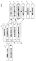
図1は本発明の第1の実施形態における車両検出装置100のブロック図である。この車両検出装置100は、現画像入力手段1、背景画像作成手段2、差分画像作成手段3、2値化画像作成手段4、外接矩形検出手段5、車両認識手段6、車両検出手段7、路面反射認識手段8、画像格納手段10を有する。画像格納手段10は、現画像格納手段11、背景画像格納手段12、差分画像格納手段13、2値化画像格納手段14を有する。
(First embodiment)
FIG. 1 is a block diagram of a
現画像入力手段1は、ビデオカメラ等により監視範囲内の現画像を逐次入力する。背景画像作成手段2は、現画像格納手段11によって格納された現画像や背景画像格納手段11によって格納された元の背景画像を基に、平均化もしくは累積することなどによって背景画像を作成する。差分画像作成手段3は、現画像格納手段11によって格納された現画像および背景画像格納手段12によって格納された背景画像の差分をとり、背景差分処理やフレーム差分処理などを用いて差分画像を作成する。2値化画像作成手段4は、差分画像格納手段13によって格納された差分画像の2値化画像を作成する。
The current image input means 1 sequentially inputs the current image within the monitoring range using a video camera or the like. The background image creation means 2 creates a background image by averaging or accumulating based on the current image stored by the current image storage means 11 and the original background image stored by the background image storage means 11. The difference image creation means 3 takes the difference between the current image stored by the current image storage means 11 and the background image stored by the background image storage means 12 and creates a difference image using background difference processing, frame difference processing, or the like. To do. The binarized
路面反射認識手段8は、現画像格納手段11によって格納された現画像の中で連続的に所定値以上の輝度を有する高輝度領域を検出して、その高輝度領域を車両のヘッドライトによる路面反射領域と認識する。路面反射認識手段8については後に詳しく説明する。外接矩形検出手段5は、2値化画像格納手段によって格納された2値化画像と、路面反射認識手段8によって認識した路面反射の影響とを考慮して車両の特徴領域となる外接矩形を検出する。車両認識手段6は、外接矩形検出手段5によって検出された外接矩形の領域に含まれる画像データに対して、パターン認識等の手法を用いて処理することにより、外接矩形内の像を車両として認識する。車両追跡手段7は、車両認識手段6によって認識された車両の追跡処理を行う。
The road surface reflection recognizing means 8 detects a high luminance area having a luminance of a predetermined value or higher continuously in the current image stored by the current image storage means 11, and uses the high luminance area as a road surface by a vehicle headlight. Recognized as a reflection area. The road surface reflection recognition means 8 will be described in detail later. The circumscribed rectangle detecting means 5 detects a circumscribed rectangle that becomes a characteristic area of the vehicle in consideration of the binarized image stored by the binarized image storing means and the influence of the road surface reflection recognized by the road surface reflection recognizing means 8. To do. The vehicle recognition means 6 recognizes an image in the circumscribed rectangle as a vehicle by processing the image data included in the circumscribed rectangle area detected by the circumscribed rectangle detecting means 5 using a technique such as pattern recognition. To do. The vehicle tracking unit 7 performs a tracking process of the vehicle recognized by the
また、現画像格納手段11は、現画像入力手段1により入力された現画像を格納する。背景画像格納手段12は、背景画像作成手段2により作成された背景画像を格納する。差分画像格納手段13は、差分画像作成手段3により作成された差分画像を格納する。2値化画像格納手段14は、2値化画像作成手段4により作成された2値化画像を格納する。
The current
ここで、現画像入力手段1は画像入力部の一例である。また、背景画像作成手段2は背景画像作成部の一例である。また、差分画像作成手段3は差分画像作成部の一例である。また、路面反射認識手段8は路面反射検出部の一例である。また、外接矩形検出手段5は車両候補領域検出部の一例である。また、車両認識手段6は車両認識部の一例である。また、車両追跡手段7は車両追跡部の一例である。
Here, the current image input means 1 is an example of an image input unit. The background image creation means 2 is an example of a background image creation unit. Moreover, the difference image creation means 3 is an example of a difference image creation unit. The road surface
次に、路面反射認識手段8について詳説する。
路面反射認識手段8は、逐次入力された現画像の中で複数に分割された所定範囲のブロック毎に輝度を計測し、計測した輝度が閾値より高い場合に高輝度領域と認識する。
Next, the road surface reflection recognition means 8 will be described in detail.
The road surface reflection recognizing means 8 measures the luminance for each block in a predetermined range divided into a plurality in the current image sequentially input, and recognizes it as a high luminance region when the measured luminance is higher than a threshold value.
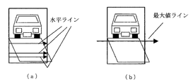
ヘッドライトの路面反射の状態は、図2(a)に示すように左右二つある場合が一般的であるが、トンネル内などカメラの設置高が低い場合には図2(b)に示すように二つの路面反射エリアが一つになって大きく広がるケースが見られる。図2は本発明の第1の実施形態におけるヘッドライトの路面反射の状態を示す図である。本実施形態ではこの特性を利用し、路面反射エリアが連続的な所定輝度以上の領域がある範囲(M×N(cm))を超えていれば路面反射領域と認識して車両領域から除去する。尚、路面反射が二つの場合でもそれぞれが所定範囲を超えていれば除去可能である。 As shown in FIG. 2 (a), the headlight road surface reflection state is generally two left and right, but when the camera installation height is low, such as in a tunnel, as shown in FIG. 2 (b). In some cases, two road surface reflection areas are expanded into one. FIG. 2 is a diagram showing a road surface reflection state of the headlight according to the first embodiment of the present invention. In the present embodiment, this characteristic is used, and if the road surface reflection area exceeds a certain range (M × N (cm)) where the area of continuous predetermined luminance or higher is exceeded, the road surface reflection area is recognized and removed from the vehicle area. . Even when there are two road surface reflections, they can be removed if each exceeds a predetermined range.
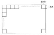
路面反射領域の除去を行うに際して、まず図3に示すように現画像の例えば4×4画素を一つのブロックとして、ブロック毎に平均輝度C_ave(i,j)(i:横、j:縦)を算出する。図3は本発明の第1の実施形態における複数のブロックに分割された現画像を示す図である。続いて、現画像の最大輝度C_maxを計測する。そして、路面反射候補として認識するために、平均輝度との比較を行う閾値C_thは、最大輝度に所定値を乗算した値とする。つまり、C_th=C_max×αとする。このαは倍率を示しており、一般的には0.7〜0.8である。閾値C_thが現画像の最小輝度C_th_min以下であれば、最小輝度を閾値とする。つまり、C_th=C_th_minとする。 When removing the road surface reflection area, first, as shown in FIG. 3, for example, 4 × 4 pixels of the current image are taken as one block, and average luminance C_ave (i, j) (i: horizontal, j: vertical) for each block. Is calculated. FIG. 3 is a diagram showing a current image divided into a plurality of blocks in the first embodiment of the present invention. Subsequently, the maximum luminance C_max of the current image is measured. And in order to recognize as a road surface reflection candidate, the threshold value C_th used for comparison with the average luminance is a value obtained by multiplying the maximum luminance by a predetermined value. That is, C_th = C_max × α. This α indicates a magnification and is generally 0.7 to 0.8. If the threshold C_th is less than or equal to the minimum luminance C_th_min of the current image, the minimum luminance is set as the threshold. That is, C_th = C_th_min.
次に、上記のブロック単位で路面反射候補の有効、無効を判定する。ここでは、平均輝度C_ave(i,j)が閾値C_th以上であれば路面反射候補として有効とする。すなわち、最大輝度に基づいて設定した閾値よりも平均輝度の度数が高ければそのブロックを路面反射候補として有効とする。このブロック毎の処理は、1画素×1画素毎に領域検出を行うラベリング処理よりも、画像処理の負荷を軽減することができる。 Next, the validity / invalidity of the road surface reflection candidate is determined for each block. Here, if the average luminance C_ave (i, j) is equal to or greater than the threshold C_th, it is considered valid as a road surface reflection candidate. That is, if the frequency of the average luminance is higher than the threshold set based on the maximum luminance, the block is validated as a road surface reflection candidate. This processing for each block can reduce the load of image processing compared to the labeling processing for detecting the area for each pixel × 1 pixel.
次に、高輝度領域の縦、横の連続性をチェックする。ここでは、上記の路面反射候補に対し、縦、横方向それぞれに路面反射として有効ブロックの連続性をチェックする。そして、図4に示すように縦M、横N(cm)以上であれば、路面反射領域と認識する。図4は本発明の第1の実施形態における路面反射領域を示す図である。例えば、縦100cm以上、横100cm以上などとする。なお、これらの解析処理はラベリング処理で行うこともできるが、負荷が重いために処理速度は遅くなる。 Next, the vertical and horizontal continuity of the high luminance area is checked. Here, the continuity of the effective blocks is checked as road surface reflection in the vertical and horizontal directions for the above road surface reflection candidates. Then, as shown in FIG. 4, if the vertical M and horizontal N (cm) or more, it is recognized as a road surface reflection region. FIG. 4 is a diagram showing a road surface reflection area in the first embodiment of the present invention. For example, the length is 100 cm or more and the width is 100 cm or more. These analysis processes can also be performed by a labeling process, but the processing speed is slowed down due to the heavy load.
次に、図5(a)の破線で示す現画像と背景画像の差分処理によって得られた上記の車両候補領域、つまり路面反射を含む車両特徴領域である差分画像から図5(b)の路面反射領域を除去し、図5(c)の実際の車両領域、つまり新たな差分画像を抽出する。図5は本発明の第1の実施形態における新差分画像の作成過程を示す図である。 Next, the road surface of FIG. 5B is obtained from the vehicle candidate area obtained by the difference processing between the current image and the background image shown by the broken line in FIG. 5A, that is, the difference image which is a vehicle characteristic area including road surface reflection. The reflection area is removed, and the actual vehicle area in FIG. 5C, that is, a new difference image is extracted. FIG. 5 is a diagram showing a process of creating a new difference image in the first embodiment of the present invention.
このような本発明の第1の実施形態の車両検出装置100によれば、輝度を計測してヘッドライトの路面反射の領域を検出することで、カメラが低い位置に設置されている場合でも、正確に車頭及び車尾を検出することができる。
According to the
次に、車両検出装置100の車両検出時の動作に関して説明する。
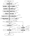
図6は本発明の第1の実施形態における車両検出装置100の動作フロー図である。
Next, the operation at the time of vehicle detection of the
FIG. 6 is an operation flowchart of the
まず、現画像入力手段1は現画像を逐次入力し、時系列的に入力された現画像や元の背景画像を基に背景画像作成手段2は背景画像を作成する。(ステップS1)続いて、差分画像作成手段3は現画像と背景画像の差分画像を作成し(ステップS2)、その差分画像から2値化画像作成手段4は2値化画像を作成する(ステップS3)。
First, the current image input means 1 sequentially inputs the current image, and the background image creation means 2 creates a background image based on the current image input in time series and the original background image. (Step S1) Subsequently, the difference
次に、路面反射認識手段4は、現画像の4×4画素(ブロック)毎の平均輝度を算出し(ステップS11)、現画像の最大輝度を算出する(ステップS12)。続いて、路面反射認識手段4は、平均輝度との比較を行い現画像の最大輝度に基づく閾値の算出し、ブロック単位での平均輝度が閾値以上であれば有効、ブロック単位での平均閾値が閾値未満であれば路面反射候補が無効であると判定する(ステップS13)。そして、路面反射認識手段4は、路面反射候補の有効部分に対して縦、横の連続性をチェックし(ステップS14)、その結果により路面反射領域の検出を行う(ステップS15)。そして、差分あり画像(路面反射を含む車両特徴領域)から路面反射領域を除外して新差分あり画像(車両領域)を特定する(ステップS16)。
Next, the road surface
次に、外接矩形検出手段5は、新差分あり画素の外接矩形を検出し(ステップS17)、車両認識手段6は、その外接矩形から特徴となる部分を車両と認識し(ステップS18)、車両追跡手段7は、車両の追跡処理に入る(S6)。また、本実施形態では、外接矩形の検出を行っているが、矩形以外の形状であってもよい。
Next, the circumscribed
このような本発明の第1の実施形態における車両検出装置100によれば、ライトを点灯した車両を検出する車両検出装置であって、逐次画像を撮像し現画像として入力する現画像入力手段11と、現画像入力手段11によって逐次入力される複数の現画像に基づいて背景画像を作成する背景画像作成手段2と、現画像および背景画像に基づいて、差分画像を作成する差分画像作成手段3と、現画像内から車両のライトによる路面反射領域を検出する路面反射認識手段8と、差分画像から路面反射領域を除いた新差分画像から特徴のある領域を有する車両候補領域を検出する外接矩形検出手段5と、車両候補領域の特徴のある領域を車両として認識する車両認識手段6とを有し、路面反射認識手段8は、現画像において所定の大きさの輝度算出領域毎に輝度を算出し、輝度のうち最大の輝度を示す最大輝度に基づいて輝度閾値を算出し、輝度との比較を行う輝度閾値を上回った輝度を有する輝度算出領域が位置的に連続することで構成する路面反射候補領域の面積が所定値より大きい場合に、路面反射候補領域を路面反射領域として検出する構成とすることで、ヘッドライトによる路面反射が1つになり広がってしまった場合でも、正確に車両の車頭及び車尾を検出することができる。
According to the
(第2の実施形態)
次に、本発明の第2の実施形態における車両検出装置200について説明する。
図7は本発明の第2の実施形態の車両検出装置の構成を示すブロック図である。同図において、第1の実施形態で説明した図1と重複する部分には同一符号を付し、説明を省略する。車両検出装置200は、路面反射認識手段8に替えて、車両確定手段9を有する。
尚、車両確定手段9は車両検出判定部の一例である。
(Second Embodiment)
Next, the
FIG. 7 is a block diagram showing the configuration of the vehicle detection apparatus according to the second embodiment of the present invention. In the figure, the same reference numerals are given to the same parts as those in FIG. 1 described in the first embodiment, and the description thereof is omitted. The
The vehicle determination means 9 is an example of a vehicle detection determination unit.
車両確定手段9は、車両認識手段6によって車両を含むと認識された外接矩形の特徴領域が所定値以上の輝度で監視範囲外の場合に、車両のヘッドライトによる路面反射領域と認識してその部分を除外することにより車両領域を確定する。
When the circumscribed rectangular feature area recognized as including the vehicle by the
この路面反射領域が認識できないと、図8に示すように遠方を走行する車両のヘッドライトによる路面反射が監視範囲内に侵入する際には、ヘッドライト光が徐々に監視範囲内に入ってきて見た目の移動距離が少なくなり、計測される車両(ヘッドライト光)の速度が小さくなり、つまり車両速度が遅いと認識されて、車両の停止や低速などの突発事象として誤報が発生する可能性があるが、車両確定手段9は、外接矩形の水平ライン毎の平均輝度を計測し、計測した平均輝度が最大値の水平ラインが監視範囲外の場合に路面反射領域と認識することが可能である。図8は本発明の第2の実施形態における遠方を走行する車両を示す図である。 If the road surface reflection area cannot be recognized, as shown in FIG. 8, when the road surface reflection by the headlight of a vehicle traveling far away enters the monitoring range, the headlight light gradually enters the monitoring range. The apparent travel distance will be reduced, the speed of the vehicle (headlight light) being measured will be reduced, that is, it will be recognized that the vehicle speed is slow, and false alarms may occur as sudden events such as vehicle stoppage or low speed. However, the vehicle determination means 9 can measure the average luminance for each horizontal line of the circumscribed rectangle, and recognize the road reflection region when the horizontal line whose measured average luminance is the maximum value is outside the monitoring range. . FIG. 8 is a diagram showing a vehicle traveling far away in the second embodiment of the present invention.
次に、車両確定手段9による水平ライン毎の平均輝度の算出について、具体的に説明する。図9は本発明の第2の実施形態における車両候補矩形内の水平ラインおよび最大値ラインを示す図である。 Next, the calculation of the average luminance for each horizontal line by the vehicle determination means 9 will be specifically described. FIG. 9 is a diagram showing a horizontal line and a maximum value line in a vehicle candidate rectangle according to the second embodiment of the present invention.
まず図9(a)に示すように、外接矩形検出手段5によって検出された車両候補矩形の水平ライン毎の平均輝度値を計測し、次に図9(b)に示すように、その平均輝度値が最大である水平ライン(最大値ライン)を検出する。そして、検出した最大値ラインが監視範囲内であるか否かを判定し、図10に示すように監視範囲外であれば、車両候補として登録を行わない。図10は本発明の第2の実施形態における車両候補の矩形が監視範囲外であることを示す図である。最大値ラインによって車両候補とするか否かを判断するのは、平均輝度値が最大の最大値ラインは、実際の車両に最も近い路面反射部分であると考えられるためである。
First, as shown in FIG. 9A, the average luminance value for each horizontal line of the vehicle candidate rectangle detected by the circumscribed
次に、車両検出装置200の車両検出時の動作に関して説明する。
図11は本発明の第2の実施形態における車両検出装置200の動作フロー図である。
Next, the operation at the time of vehicle detection of the
FIG. 11 is an operation flowchart of the
まず、現画像入力手段1は現画像を逐次入力し、背景画像作成手段2は時系列的に入力された現画像や元の背景画像を基に背景画像を作成し(ステップS1)、差分画像作成手段3は差分処理により現画像と背景画像との差分画像を作成する(ステップS2)。続いて、その差分画像から2値化画像作成手段4は2値化画像を作成し(ステップS3)、外接矩形検出手段5は差分のあった画素の外接矩形を検出する(ステップS4)。そして、車両認識手段6は検出した外接矩形の特徴部分を車両として認識する(ステップS5)。また、本実施形態では、外接矩形の検出を行っているが、矩形以外の形状であってもよい。
First, the current image input means 1 sequentially inputs the current image, and the background image creation means 2 creates a background image based on the current image input in time series and the original background image (step S1), and the difference image The creation means 3 creates a difference image between the current image and the background image by difference processing (step S2). Subsequently, the binarized
次に、車両確定手段9は、検出された外接矩形である車両候補矩形の水平ライン毎の平均輝度を算出し(ステップS21)、続いて平均輝度の最大値(最大平均輝度をCmax、最大値ラインをIラインとする)を算出する(ステップS22)。そして、車両確定手段9は、最大値ラインの最大平均輝度Cmaxが所定の輝度を示す輝度閾値Cmax_th以上か否かを判断し(ステップS23)、大きければその最大値ラインが監視範囲内か否かを判断する(ステップS24)。最大値ラインが監視範囲内であれば、車両確定手段9は、その車両候補矩形を車両として確定して登録し(ステップS26)、登録した車両の追跡処理を行う(ステップS6)。尚、最大値ラインの最大平均輝度Cmaxが輝度閾値Cmax_thよりも大きい場合、かつ最大値ラインが監視範囲外である場合には、車両確定手段9は、車両の確定および登録を行わずに処理を終了する(ステップS25)。
Next, the vehicle determination means 9 calculates the average brightness for each horizontal line of the detected vehicle candidate rectangle, which is a circumscribed rectangle (step S21), and then the maximum value of the average brightness (the maximum average brightness is Cmax, the maximum value). The line is defined as I line) (step S22). Then, the
このような本発明の第2の実施形態における車両検出装置200は、逐次画像を撮像し現画像として入力する現画像入力手段1と、現画像入力手段1によって逐次入力される複数の現画像に基づいて背景画像を作成する背景画像作成手段2と、現画像および背景画像に基づいて、差分画像を作成する差分画像作成手段3と、差分画像から特徴のある領域を有する車両候補領域を検出する外接矩形検出手段5と、車両候補領域の前記特徴のある領域を車両として認識する車両認識手段6と、車両の所在する位置に基づいて、車両検出の有無を判定する車両確定手段9とを有し、車両確定手段9は、車両候補領域において水平ライン毎に平均輝度値を算出し、平均輝度値のうち最大のものを有する水平ラインを示す最大値ラインを抽出し、最大値ラインが所定領域の範囲内に位置する場合にのみ認識車両を車両として検出する構成とすることで、監視範囲に進入前の車両の検出を防止することができる。
Such a
本発明は、ヘッドライトによる路面反射が1つになり広がってしまった場合でも、正確に車両の車頭及び車尾を検出することができる車両検出装置等に有用である。また、監視範囲に進入前の車両の検出を防止することができる車両検出装置等に有用である。 INDUSTRIAL APPLICABILITY The present invention is useful for a vehicle detection device or the like that can accurately detect the head and tail of a vehicle even when the road surface reflection by the headlight becomes one and spreads. Further, the present invention is useful for a vehicle detection device that can prevent detection of a vehicle before entering the monitoring range.
100 車両検出装置
1 現画像入力手段
2 背景画像作成手段
3 差分画像作成手段
4 2値化画像作成手段
5 外接矩形検出手段
6 車両認識手段
7 車両追跡手段
8 路面反射認識手段
9 車両確定手段
10 画像格納手段
11 現画像格納手段
12 背景画像格納手段
13 差分画像格納手段
14 2値化画像格納手段
200 車両検出装置
DESCRIPTION OF
Claims (6)
逐次画像を撮像し現画像として入力する画像入力部と、
前記画像入力部によって逐次入力される複数の現画像に基づいて背景画像を作成する背景画像作成部と、
前記現画像および前記背景画像に基づいて、差分画像を作成する差分画像作成部と、
前記現画像内から前記車両のライトによる路面反射領域を検出する路面反射検出部と、
前記差分画像から前記路面反射領域を除いた新差分画像から特徴のある領域を有する車両候補領域を検出する車両候補領域検出部と、
前記車両候補領域の前記特徴のある領域を車両として認識する車両認識部と、
を有し、
前記路面反射検出部は、
前記現画像において所定の大きさの輝度算出領域毎に輝度を算出し、
前記輝度のうち最大の輝度を示す最大輝度に基づいて輝度閾値を算出し、
前記輝度との比較を行う前記輝度閾値を上回った輝度を有する前記輝度算出領域が位置的に連続することで構成する路面反射候補領域の面積が所定値より大きい場合に、前記路面反射候補領域を前記路面反射領域として検出する車両検出装置。 A vehicle detection device for detecting a vehicle that has turned on a light,
An image input unit that sequentially captures images and inputs them as current images;
A background image creation unit that creates a background image based on a plurality of current images sequentially input by the image input unit;
A difference image creation unit for creating a difference image based on the current image and the background image;
A road surface reflection detection unit for detecting a road surface reflection area by the light of the vehicle from within the current image;
A vehicle candidate area detection unit for detecting a vehicle candidate area having a characteristic area from the new difference image obtained by removing the road surface reflection area from the difference image;
A vehicle recognition unit that recognizes the characteristic area of the vehicle candidate area as a vehicle;
Have
The road surface reflection detector is
Calculating the brightness for each brightness calculation area of a predetermined size in the current image;
A luminance threshold is calculated based on the maximum luminance indicating the maximum luminance among the luminances;
When the area of the road surface reflection candidate area constituted by the position of the luminance calculation area having a luminance that exceeds the luminance threshold for comparison with the luminance is consecutively greater than a predetermined value, the road surface reflection candidate area is A vehicle detection device that detects the road surface reflection area.
前記車両を追跡する車両追跡部を有する車両検出装置。 The vehicle detection device according to claim 1,
The vehicle detection apparatus which has a vehicle tracking part which tracks the said vehicle.
前記画像入力部によって逐次入力される複数の現画像に基づいて背景画像を作成する背景画像作成部と、
前記現画像および前記背景画像に基づいて、差分画像を作成する差分画像作成部と、
前記差分画像から特徴のある領域を有する車両候補領域を検出する車両候補領域検出部と、
前記車両候補領域の前記特徴のある領域を車両として認識する車両認識部と、
前記車両の所在する位置に基づいて、車両検出の有無を判定する車両検出判定部と
を有し、
前記車両検出判定部は、
前記車両候補領域において水平ライン毎に平均輝度値を算出し、
前記平均輝度値のうち最大のものを有する水平ラインを示す最大値ラインを抽出し、
前記最大値ラインが所定領域の範囲内に位置する場合にのみ前記認識車両を車両として検出する車両検出装置。 An image input unit that sequentially captures images and inputs them as current images;
A background image creation unit that creates a background image based on a plurality of current images sequentially input by the image input unit;
A difference image creation unit for creating a difference image based on the current image and the background image;
A vehicle candidate area detection unit for detecting a vehicle candidate area having a characteristic area from the difference image;
A vehicle recognition unit that recognizes the characteristic area of the vehicle candidate area as a vehicle;
A vehicle detection determination unit that determines presence or absence of vehicle detection based on a position where the vehicle is located;
The vehicle detection determination unit
Calculating an average luminance value for each horizontal line in the vehicle candidate region;
Extracting a maximum value line indicating a horizontal line having a maximum one of the average luminance values;
A vehicle detection device that detects the recognized vehicle as a vehicle only when the maximum value line is located within a predetermined region.
前記車両検出判定部によって車両が検出された場合、前記車両を追跡する車両追跡部を有する車両検出装置。 The vehicle detection device according to claim 3,
The vehicle detection apparatus which has a vehicle tracking part which tracks the said vehicle, when a vehicle is detected by the said vehicle detection determination part.
逐次画像が撮像され現画像として入力される画像入力ステップと、
前記画像入力ステップにおいて逐次入力される複数の現画像に基づいて背景画像が作成されるステップと、
前記現画像および前記背景画像に基づいて、差分画像が作成されるステップと、
前記現画像内から前記車両のライトによる路面反射領域が検出される路面反射検出ステップと、
前記差分画像から前記路面反射領域を除いた新差分画像から特徴のある領域を有する車両候補領域が検出されるステップと、
前記車両候補領域の前記特徴のある領域が車両として認識されるステップと、
を有し、
前記路面反射検出ステップは、
前記現画像において所定の大きさの輝度算出領域毎に輝度が算出され、
前記輝度のうち最大の輝度を示す最大輝度に基づいて輝度閾値が算出され、
前記輝度との比較を行う前記輝度閾値を上回った輝度を有する前記輝度算出領域が位置的に連続することで構成する路面反射候補領域の面積が所定値より大きい場合に、前記路面反射候補領域が前記路面反射領域として検出される車両検出方法。 A vehicle detection method in which a vehicle with a light turned on is detected,
An image input step in which sequential images are captured and input as the current image;
A step of creating a background image based on a plurality of current images sequentially input in the image input step;
A difference image is created based on the current image and the background image;
A road surface reflection detection step in which a road surface reflection area by the light of the vehicle is detected from within the current image;
A vehicle candidate area having a characteristic area is detected from a new difference image obtained by removing the road surface reflection area from the difference image;
Recognizing the characteristic area of the vehicle candidate area as a vehicle;
Have
The road surface reflection detection step includes:
Luminance is calculated for each luminance calculation area of a predetermined size in the current image,
A luminance threshold is calculated based on the maximum luminance indicating the maximum luminance among the luminances,
When the area of the road surface reflection candidate region formed by the position of the luminance calculation region having a luminance that exceeds the luminance threshold value for comparison with the luminance is consecutively greater than a predetermined value, the road surface reflection candidate region is A vehicle detection method detected as the road surface reflection area.
前記画像入力ステップにおいて逐次入力される複数の現画像に基づいて背景画像が作成されるステップと、
前記現画像および前記背景画像に基づいて、差分画像が作成されるステップと、
前記差分画像から特徴のある領域を有する車両候補領域が検出されるステップと、
前記車両候補領域の前記特徴のある領域が車両として認識される車両認識部と、
前記車両の所在する位置に基づいて、車両検出の有無が判定される車両検出判定ステップと、
を有し、
前記車両検出判定ステップは、
前記車両候補領域において水平ライン毎に平均輝度値が算出され、
前記平均輝度値のうち最大のものを有する水平ラインを示す最大値ラインが抽出され、
前記最大値ラインが所定領域の範囲内に位置する場合にのみ前記認識車両が車両として検出される車両検出方法。 An image input step in which sequential images are captured and input as current images;
A step of creating a background image based on a plurality of current images sequentially input in the image input step;
A difference image is created based on the current image and the background image;
A vehicle candidate area having a characteristic area is detected from the difference image;
A vehicle recognition unit for recognizing the characteristic area of the vehicle candidate area as a vehicle;
A vehicle detection determination step in which presence / absence of vehicle detection is determined based on a position where the vehicle is located;
Have
The vehicle detection determination step includes
An average luminance value is calculated for each horizontal line in the vehicle candidate area,
A maximum value line indicating a horizontal line having a maximum one of the average luminance values is extracted,
A vehicle detection method in which the recognized vehicle is detected as a vehicle only when the maximum value line is located within a predetermined region.
Priority Applications (1)
| Application Number | Priority Date | Filing Date | Title |
|---|---|---|---|
| JP2006089068A JP2007265016A (en) | 2006-03-28 | 2006-03-28 | Vehicle detection device and vehicle detection method |
Applications Claiming Priority (1)
| Application Number | Priority Date | Filing Date | Title |
|---|---|---|---|
| JP2006089068A JP2007265016A (en) | 2006-03-28 | 2006-03-28 | Vehicle detection device and vehicle detection method |
Publications (1)
| Publication Number | Publication Date |
|---|---|
| JP2007265016A true JP2007265016A (en) | 2007-10-11 |
Family
ID=38637943
Family Applications (1)
| Application Number | Title | Priority Date | Filing Date |
|---|---|---|---|
| JP2006089068A Withdrawn JP2007265016A (en) | 2006-03-28 | 2006-03-28 | Vehicle detection device and vehicle detection method |
Country Status (1)
| Country | Link |
|---|---|
| JP (1) | JP2007265016A (en) |
Cited By (6)
| Publication number | Priority date | Publication date | Assignee | Title |
|---|---|---|---|---|
| JP2012203688A (en) * | 2011-03-25 | 2012-10-22 | Mitsubishi Electric Corp | Foreign matter detection device |
| KR101303758B1 (en) | 2012-06-13 | 2013-09-06 | 주식회사 만도 | Camera system and control method there of |
| WO2014017302A1 (en) | 2012-07-27 | 2014-01-30 | クラリオン株式会社 | Vehicle-mounted surrounding environment recognition device |
| EP2879384A4 (en) * | 2012-07-27 | 2016-04-20 | Nissan Motor | Three-dimensional object detection device, and three-dimensional object detection method |
| US20190163994A1 (en) * | 2017-11-28 | 2019-05-30 | Kabushiki Kaisha Toshiba | Image feature emphasis device, road surface feature analysis device, image feature emphasis method, and road surface feature analysis method |
| CN111274982A (en) * | 2020-02-04 | 2020-06-12 | 浙江大华技术股份有限公司 | Method and device for identifying projectile and storage medium |
-
2006
- 2006-03-28 JP JP2006089068A patent/JP2007265016A/en not_active Withdrawn
Cited By (13)
| Publication number | Priority date | Publication date | Assignee | Title |
|---|---|---|---|---|
| JP2012203688A (en) * | 2011-03-25 | 2012-10-22 | Mitsubishi Electric Corp | Foreign matter detection device |
| KR101303758B1 (en) | 2012-06-13 | 2013-09-06 | 주식회사 만도 | Camera system and control method there of |
| US9558546B2 (en) | 2012-07-27 | 2017-01-31 | Nissan Motor Co., Ltd. | Three-dimensional object detection device, and three-dimensional object detection method |
| CN104508722A (en) * | 2012-07-27 | 2015-04-08 | 歌乐株式会社 | Vehicle-mounted surrounding environment recognition device |
| EP2879384A4 (en) * | 2012-07-27 | 2016-04-20 | Nissan Motor | Three-dimensional object detection device, and three-dimensional object detection method |
| CN104508722B (en) * | 2012-07-27 | 2016-08-24 | 歌乐株式会社 | Vehicle-mounted surrounding identification device |
| WO2014017302A1 (en) | 2012-07-27 | 2014-01-30 | クラリオン株式会社 | Vehicle-mounted surrounding environment recognition device |
| RU2619059C2 (en) * | 2012-07-27 | 2017-05-11 | Ниссан Мотор Ко., Лтд. | Device for detecting three-dimensional objects and method for detecting three-dimensional objects |
| US9721460B2 (en) | 2012-07-27 | 2017-08-01 | Clarion Co., Ltd. | In-vehicle surrounding environment recognition device |
| US20190163994A1 (en) * | 2017-11-28 | 2019-05-30 | Kabushiki Kaisha Toshiba | Image feature emphasis device, road surface feature analysis device, image feature emphasis method, and road surface feature analysis method |
| US10872247B2 (en) * | 2017-11-28 | 2020-12-22 | Kabushiki Kaisha Toshiba | Image feature emphasis device, road surface feature analysis device, image feature emphasis method, and road surface feature analysis method |
| CN111274982A (en) * | 2020-02-04 | 2020-06-12 | 浙江大华技术股份有限公司 | Method and device for identifying projectile and storage medium |
| CN111274982B (en) * | 2020-02-04 | 2023-04-07 | 浙江大华技术股份有限公司 | Method and device for identifying projectile and storage medium |
Similar Documents
| Publication | Publication Date | Title |
|---|---|---|
| US7436982B2 (en) | Vehicle surroundings monitoring apparatus | |
| US9619895B2 (en) | Image processing method of vehicle camera and image processing apparatus using the same | |
| JPH08166221A (en) | Vehicle recognizing device for night | |
| US20140002658A1 (en) | Overtaking vehicle warning system and overtaking vehicle warning method | |
| JP2007265016A (en) | Vehicle detection device and vehicle detection method | |
| US8160300B2 (en) | Pedestrian detecting apparatus | |
| WO2013191078A1 (en) | Object detection device for area around vehicle | |
| JP2007066003A (en) | Stop-line detection device | |
| JP4762830B2 (en) | Perimeter monitoring system | |
| JP2005090974A (en) | Preceding car recognition device | |
| JP2013047878A (en) | Road situation grasping device | |
| JP2009146153A (en) | Moving object detection device, moving object detection method and moving object detection program | |
| JP2010093569A (en) | Vehicle periphery monitoring device | |
| JP4321410B2 (en) | Object detection apparatus and method | |
| KR20160137162A (en) | Method for detecting biased vehicle and apparatus thereof | |
| KR101294498B1 (en) | Method of objects recognition for tunnel accident monitoring system | |
| JP4842301B2 (en) | Pedestrian detection device and program | |
| JP3844750B2 (en) | Infrared image recognition device and alarm device using infrared image recognition device | |
| JP2006268678A (en) | Device and method for detecting stopping or low-speed vehicle | |
| JP6177632B2 (en) | Vehicle position detection device and vehicle rear side warning device | |
| JP4074571B2 (en) | Traffic flow measuring device | |
| JP4239834B2 (en) | Object detection device | |
| JP4995555B2 (en) | Image processing device | |
| JP4922642B2 (en) | Vehicle detection device and vehicle detection method | |
| CN114730520A (en) | Signal machine identification method and signal machine identification device |
Legal Events
| Date | Code | Title | Description |
|---|---|---|---|
| RD02 | Notification of acceptance of power of attorney |
Free format text: JAPANESE INTERMEDIATE CODE: A7422 Effective date: 20071113 |
|
| RD04 | Notification of resignation of power of attorney |
Free format text: JAPANESE INTERMEDIATE CODE: A7424 Effective date: 20071120 |
|
| A300 | Withdrawal of application because of no request for examination |
Free format text: JAPANESE INTERMEDIATE CODE: A300 Effective date: 20090602 |