JP2007256559A - Display device with four-display-direction switching function - Google Patents
Display device with four-display-direction switching function Download PDFInfo
- Publication number
- JP2007256559A JP2007256559A JP2006080087A JP2006080087A JP2007256559A JP 2007256559 A JP2007256559 A JP 2007256559A JP 2006080087 A JP2006080087 A JP 2006080087A JP 2006080087 A JP2006080087 A JP 2006080087A JP 2007256559 A JP2007256559 A JP 2007256559A
- Authority
- JP
- Japan
- Prior art keywords
- display
- liquid crystal
- segments
- direction switching
- type
- Prior art date
- Legal status (The legal status is an assumption and is not a legal conclusion. Google has not performed a legal analysis and makes no representation as to the accuracy of the status listed.)
- Pending
Links
Images


Landscapes
- Liquid Crystal (AREA)
- Indicating Measured Values (AREA)
- Liquid Crystal Display Device Control (AREA)
- Control Of Indicators Other Than Cathode Ray Tubes (AREA)
Abstract
Description
本発明は、表示方向が上下左右の4方向に切替可能である、電力量等の数字を主に表示する表示装置に関するものである。 The present invention relates to a display device that mainly displays numbers such as electric energy, the display direction of which can be switched between four directions of up, down, left and right.
近年の地球環境問題への意識向上にともない、電力エネルギーにおいてもきめ細かく管理する必要性が生じており、既存の分電盤や機械設備に取り付けるための小型化を実現した配線用遮断器形の電子式電力量計が既に知られている。 With the recent increase in awareness of global environmental issues, the need to meticulously manage electric power energy has arisen, and circuit breaker-type electronic devices that have been reduced in size to be installed on existing distribution boards and mechanical equipment. An energy meter is already known.
従来1方向接続であった配線用遮断器形の電子式電力量計は、その形状がゆえに4方向接続(上、下、左、右)の要求が発生し、この4方向接続に対応するために、図9に示されるようにそれぞれ4機種を揃えていた。 The circuit breaker-type electronic watt-hour meter that used to be a one-way connection in the past has a demand for four-way connection (up, down, left, right) because of its shape, so that it can handle this four-way connection. In addition, as shown in FIG.
図9において、(a)はTタイプ(上側電源接続タイプ)であり、(b)はBタイプ(下側電源接続タイプ)であり、(c)はLタイプ(左側電源接続タイプ)であり、(d)はRタイプ(右側電源接続タイプ)である。101は電子式電力量計の筐体、102は電源側端子ねじ、103は負荷側端子ねじ、104は複数組の液晶表示7セグメントからなる計量表示部、105は液晶表示による動作表示部である。 In FIG. 9, (a) is a T type (upper power connection type), (b) is a B type (lower power connection type), (c) is an L type (left power connection type), (D) is R type (right power supply connection type). 101 is a housing of an electronic watt-hour meter, 102 is a power supply side terminal screw, 103 is a load side terminal screw, 104 is a metering display unit composed of a plurality of sets of 7 segments of liquid crystal display, and 105 is an operation display unit by liquid crystal display. .
4機種を揃えるため、1機種に比べて機種数が4倍となり、電子式電力量計の製造および管理上の手間が掛かっていた。 Since four models were prepared, the number of models was four times that of one model, which required time and effort for manufacturing and managing an electronic watt-hour meter.
上述した問題点を解決するものとして、従来、計量表示部(液晶表示)を機器本体に対して機械的に回動可能とした表示装置が特開2003−315363号公報(特許文献1)に記載されている。 As a solution to the above-described problems, a display device in which a measurement display unit (liquid crystal display) is mechanically rotatable with respect to a device main body is described in Japanese Patent Application Laid-Open No. 2003-315363 (Patent Document 1). Has been.
これは、計量表示部を機器本体から水平方向に引き出し、表示方向(設置方向)に合わせて回転させた後に元の位置に戻すことによって、計量表示部を機器本体の表示方向に合わせることができる。計量表示部を機器本体から垂直に引き出すのではなく、水平方向に引き出してから回転させる構成としたことにより、分電盤用機器の寸法規制を満足することを可能としたものである。 This is because the weighing display unit can be aligned with the display direction of the device body by pulling the weighing display unit horizontally from the device body, rotating it in accordance with the display direction (installation direction) and then returning it to the original position. . Rather than pulling out the weighing display portion vertically from the device main body, it is possible to satisfy the dimensional regulation of the device for the distribution board by adopting a configuration in which it is pulled out in the horizontal direction and then rotated.
また、図10に示される電子式電力量計が従来知られている。これは、計量表示部を機械的に回動させることなく、表示方向切替スイッチ106の操作にて計量表示部107の表示パターンを切り替えることによって計量値および計量単位などの表示方向を機器本体の設置方向に合わせることを可能としたものである。図10(a)に示されるものは図9のTタイプに相当するものである。表示方向切替スイッチ106を右側に切り替えると、図10(b)に示されるように、Rタイプの表示パターンに切り替えられる。表示方向切替スイッチ106を左側に切り替えると、図10(c)に示されるように、Lタイプの表示パターンに切り替えられる。
An electronic watt-hour meter shown in FIG. 10 is conventionally known. This is because the display direction of the measurement value and the measurement unit can be set by changing the display pattern of the
図10に示されるものは、計量値表示をドットマトリクス液晶表示器で行うことにより、計量値等の表示方向を機器本体の設置方向(3方向)に合わせることができる。 In the case shown in FIG. 10, the measurement value is displayed on the dot matrix liquid crystal display, so that the display direction of the measurement value and the like can be adjusted to the installation direction (three directions) of the apparatus main body.
また、タイムスイッチにおいても、時刻表示をドットマトリクス液晶表示器で行うことにより、表示方向をタイムスイッチの設置方向に合わせることができるものが特許第3308660号公報(引用文献2)に示されている。
特許文献1に示されるものは、計量表示部が固定されている機器に比べ、次のとおり余計な部品を必要とする。
・計量表示部を水平方向に引き出し、摺動させて移動させるための支持部品
・計量表示部を回転させるための支持部品
・計量表示部を90度回転するごとに固定するための支持部品
・計量表示部を機器本体に固定するための部品
・計量表示部を機器本体内部の電子回路基板と接続するための中継基板および接続ケーブル
これらの部品の製造、組立および調整に要する原価のため、計量表示部が固定されている機器に比べ、確実に製造原価の増大を招く。
The thing shown by
・ Support parts for pulling out the weighing display part horizontally and moving it by sliding ・ Support parts for rotating the weighing display part ・ Supporting parts for fixing the weighing display part every 90 degrees Parts and weighing display parts for fixing the display unit to the device body Relay board and connection cable for connecting the electronic circuit board inside the device body The weighing display for the cost required to manufacture, assemble and adjust these parts Compared to equipment with fixed parts, the manufacturing cost is certainly increased.
また、計量表示部を機器本体から水平方向に引き出し、設置方向に合わせて回転させた後、元の位置に戻す、という一連の動作は、動作の途中で計量表示部に無理な加重を加えたり、計量表示部と機器本体の間に異物が混入したりした場合は、動作不良や故障に繋がる。そのため、計量表示部の回転を行う際は、慎重な作業が要求され、使い勝手が悪くなる。 In addition, the series of operations in which the weighing display unit is pulled out from the instrument body in the horizontal direction, rotated in accordance with the installation direction, and then returned to the original position, may cause an excessive load on the weighing display unit during operation. If foreign matter is mixed between the weighing display unit and the device main body, it may lead to malfunction or failure. Therefore, when rotating the measurement display unit, careful work is required, and usability is deteriorated.
図10および特許文献2に示されるものは、数字表示にドットマトリクス液晶表示器を使用することを前提としている。一般的な液晶表示器は、7セグメントとドットマトリクスに大別され、各々最適な用途が異なる。
The thing shown in FIG. 10 and
ドットマトリクス液晶表示器は、表示する文字や図形をドット(画素)、すなわち、細かい点の集まりとして表示する。したがって、ドットを細かくすれば複雑な形状の表示も可能であり、主として図形や画像の表示に使用される。一方、7セグメント液晶表示器は、台形、六角形、あるいは長方形のセグメント(素子)を7個組み合わせて一組としたものである。7個のセグメントの表示の組み合わせによって、主として数字や一部のアルファベットの表示に使用される。 The dot matrix liquid crystal display displays characters and figures to be displayed as dots (pixels), that is, a collection of fine dots. Therefore, if the dots are made fine, it is possible to display a complicated shape, which is mainly used for displaying graphics and images. On the other hand, the seven-segment liquid crystal display is a combination of seven trapezoidal, hexagonal, or rectangular segments (elements). It is mainly used for displaying numbers and some alphabets by combining the display of 7 segments.
このように、両者はその構成や用途が異なるが、表示単位を点灯するか消灯するかによって表示状態を変える、という表示の原理は同様である。この表示単位は、ドットマトリクス液晶表示器ではドット1個、7セグメント液晶表示器ではセグメント1個に相当する。 Thus, although both have different configurations and uses, the display principle of changing the display state depending on whether the display unit is turned on or off is the same. This display unit corresponds to one dot in a dot matrix liquid crystal display and one segment in a 7 segment liquid crystal display.
したがって、例えば数字の「7」を表示する場合、7セグメント液晶表示器では4個のセグメントを点灯するだけで済むが、ドットマトリクス液晶表示では何倍もの数のドットを点灯しなければならない。 Therefore, for example, when displaying the number “7”, it is only necessary to light four segments in a 7-segment liquid crystal display, but many times as many dots must be lighted in a dot matrix liquid crystal display.
表示単位には各々電極を配置して配線する必要があるため、表示単位が多くなればそれに比例して電極や配線の数も多くなり、液晶表示器本体の構造が複雑になる。それに伴い、液晶表示器の表示を制御するための駆動回路の構成も複雑になり、さらには、駆動回路を制御するためのソフトウェアの構成も複雑になる。 Since it is necessary to arrange and wire each display unit with electrodes, as the number of display units increases, the number of electrodes and wiring increases in proportion thereto, and the structure of the liquid crystal display main body becomes complicated. Along with this, the configuration of the drive circuit for controlling the display of the liquid crystal display is also complicated, and further, the configuration of the software for controlling the drive circuit is also complicated.
計量値表示のように、主として数字を表示する目的のためにドットマトリクス液晶表示器を使用した場合、7セグメント液晶表示器に比べ、表示器本体の原価は言うまでもなく、駆動回路の製造原価、およびソフトウェア作成の原価が確実に増大する。 When a dot matrix liquid crystal display is used mainly for the purpose of displaying numbers, such as weighing value display, the manufacturing cost of the drive circuit, not to mention the cost of the display body, compared to the 7-segment liquid crystal display, and The cost of creating software will definitely increase.
また、ドットマトリクス液晶表示器は、画素数が多くなればなるほど、いわゆるドット欠け(一部のドットが点灯しない、または点灯したまま消灯しない不良状態)が起こり易くなるという欠点がある。7セグメント液晶表器でもセグメントの点灯不良が起こることはあるが、セグメントの数はドットマトリクス液晶表示器のドットに比べれば格段に少ないので、点灯不良が起こる確率は格段に低くなる。 In addition, the dot matrix liquid crystal display has a drawback that so-called dot missing (a defective state in which some dots are not lit or not turned off while being lit) is more likely to occur as the number of pixels increases. Although the segment lighting failure may occur even in the 7-segment liquid crystal display device, the number of segments is remarkably smaller than the dots of the dot matrix liquid crystal display device, so the probability of the lighting failure occurring is significantly lower.
(本発明の目的)
本発明の目的は、表示パターン切替による4表示方向に対応するための液晶表示7セグメントのセグメント数を最少限に抑え、コストダウンを図ることのできる4表示方向切替機能付き表示装置を提供することである。
(Object of the present invention)
SUMMARY OF THE INVENTION An object of the present invention is to provide a display device with a 4-display-direction switching function that can minimize the number of segments of the liquid crystal display 7-segment to cope with four display directions by switching display patterns and can reduce costs. It is.
上記目的を達成するために、本発明は、上方向に対応する第1の表示パターン、左方向に対応する第2の表示パターン、下方向に対応する第3の表示パターンおよび右方向に対応する第4の表示パターンが、複数組の液晶表示7セグメントの組み合わせによって形成されている表示手段と、前記第1ないし第4の表示パターンのいずれかを選択させるための表示方向切替操作手段と、該表示方向切替操作手段の操作に応じて前記第1ないし第4の表示パターンのいずれかを選択し、表示動作を行わせる表示方向切替手段とを有する4表示方向切替機能付き表示装置とするものである。
In order to achieve the above object, the present invention corresponds to a first display pattern corresponding to the upward direction, a second display pattern corresponding to the left direction, a third display pattern corresponding to the downward direction, and a right direction. A display means in which the fourth display pattern is formed by a combination of a plurality of
本発明によれば、表示パターン切替による4表示方向に対応するための液晶表示7セグメントのセグメント数を最少限に抑え、コストダウンを図ることができる。 According to the present invention, it is possible to reduce the number of segments of the seven segments of the liquid crystal display for corresponding to the four display directions by switching the display pattern, thereby reducing the cost.
本発明を実施するための最良の形態は後述する実施例1および2に記載の通りである。 The best mode for carrying out the present invention is as described in Examples 1 and 2 described later.
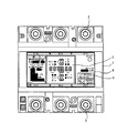
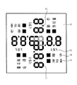
図1ないし図4に本発明の実施例1である配線用遮断器形の電子式電力量計を示す。図1はその正面図を示し、1は電子式電力量計の筐体、2は電源側端子ねじ、3は負荷側端子ねじ、4は銘板、5は銘板4の中央部分に位置する表示手段(液晶表示器)である。図2は表示手段5を拡大して示す図である。図1および図2は全てのセグメントを表示状態(全点灯状態)としたものである。6は押しボタン式の表示方向切替スイッチである。
1 to 4 show a circuit breaker type electronic watt-hour meter which is
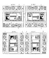
表示手段5は、図3に示されるように、上方向に対応するTタイプ(第1)の表示パターン7、右方向に対応するRタイプ(第2)の表示パターン8、下方向に対応するBタイプ(第3)の表示パターン9および左方向に対応するLタイプ(第4)の表示パターン10が、複数組の液晶表示7セグメント11(図2)の組み合わせによって形成されているものである。液晶表示セグメント11はすべて形状及び大きさが同一である。そして、表示方向切替スイッチ6のオン毎に、表示パターン7ないし10が順次切り替えられる。
As shown in FIG. 3, the display means 5 corresponds to the T type (first)
図2に示されるように、表示手段5は、上下方向と左右方向の十字状に複数組の液晶表示7セグメント11が配列されることによって形成される。その十字状の交差部分では4つの液晶表示7セグメント11がブロック状に組み付けられ、表示パターン7ないし10に共通に使用される液晶表示セグメント(図2でハッチングされたセグメント)を含む。十字状の複数組の液晶表示7セグメント11および小数点表示用の液晶表示セグメント12が計量表示部を構成する。13は計量単位表示部を構成する液晶表示セグメントである。そして、動作を表示するための液晶表示セグメント14および無計量を表示するための液晶表示セグメント15が動作表示部を構成する。
As shown in FIG. 2, the display means 5 is formed by arranging a plurality of sets of
上記計量表示部、計量単位表示部および動作表示部は、図3に示されるように、各表示パターン7ないし10に含まれる。したがって、筐体1の設置方向が図4に示されるように変わると、表示手段5における表示方向もそれに応じて計量表示部と同様に変わる。したがって、表示手段5における表示を読み取り易くすることができる。
The measurement display unit, the measurement unit display unit, and the operation display unit are included in the
なお、図4において、銘板4の文字方向は、TタイプおよびRタイプの場合と、BタイプおよびLタイプの場合とは異なっている。これは、発注を受けた時点で表示方向が指定されている場合にはその表示方向に対応した文字方向の銘板4を製造過程で貼り付けている例を示しているからである。銘板4の文字方向がTタイプのみに対応したものであっても良いことは言うまでもない。 In FIG. 4, the character direction of the nameplate 4 is different between the T type and R type and the B type and L type. This is because when the display direction is specified at the time of receiving the order, the nameplate 4 in the character direction corresponding to the display direction is pasted in the manufacturing process. It goes without saying that the character direction of the nameplate 4 may correspond to only the T type.
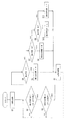
図5のフローチャートによって電子式電力量計に備えられたCPUの表示方向切替動作を説明する。 The display direction switching operation of the CPU provided in the electronic watt-hour meter will be described with reference to the flowchart of FIG.
ステップS1では初期化処理を行う。ステップS2では表示方向切替スイッチ6がオフになっているか否かを判別する。オフとは表示方向切替スイッチ6が押されていない状態のことであり、オンとは表示方向切替スイッチ6が押されている状態のことである。
In step S1, initialization processing is performed. In step S2, it is determined whether or not the display
オフであれば、ステップS3でオンになるまで待ち、オンになるとステップS4に進む。ステップS2およびS3は、表示方向切替スイッチ6のオンから一度オフを検出しないと次のオンを検出しないようにして、オンしたままで順次表示方向が切り替わることのないようにするルーチンである。
If it is off, it waits until it is turned on in step S3, and if it is on, it proceeds to step S4. Steps S <b> 2 and S <b> 3 are routines that do not detect the next turn-on unless the turn-off of the display direction change-over
ステップS4では、EEPROMなどの記憶手段(不図示)に記憶されている表示方向(表示パターン)を読み出し、その表示方向がTタイプであるか否かを判定する。Tタイプであれば、それが現在の表示方向であるとして、ステップS5で表示方向をRタイプに切り替える。そして、ステップS6にて切り替えた表示方向、すなわちRタイプに前記記憶手段の内容を書き換える。 In step S4, the display direction (display pattern) stored in storage means (not shown) such as an EEPROM is read out, and it is determined whether or not the display direction is the T type. If it is T type, it is assumed that it is the current display direction, and the display direction is switched to R type in step S5. Then, the contents of the storage means are rewritten to the display direction switched in step S6, that is, the R type.
ステップS4にて読み出した表示方向がTタイプでないと判定するとステップS7へ進み、Rタイプか否かを判定する。Rタイプであれば、それが現在の表示方向であるとして、ステップS8で表示方向をBタイプに切り替える。そして、ステップS6にて切り替えた表示方向、すなわちBタイプに前記記憶手段の内容を書き換える。 If it determines with the display direction read in step S4 not being T type, it will progress to step S7 and it will be determined whether it is R type. If it is the R type, it is assumed that it is the current display direction, and the display direction is switched to the B type in step S8. Then, the contents of the storage means are rewritten to the display direction switched in step S6, that is, the B type.
ステップS7にて読み出した表示方向がRタイプでないと判定するとステップS9へ進み、Bタイプか否かを判定する。Bタイプであれば、それが現在の表示方向であるとして、ステップS10で表示方向をLタイプに切り替える。そして、ステップS6にて切り替えた表示方向、すなわちLタイプに前記記憶手段の内容を書き換える。 If it is determined that the display direction read in step S7 is not the R type, the process proceeds to step S9 to determine whether it is the B type. If it is the B type, it is assumed that it is the current display direction, and the display direction is switched to the L type in step S10. Then, the contents of the storage means are rewritten to the display direction switched in step S6, that is, the L type.
ステップS9にて読み出した表示方向がBタイプでないと判定するとステップS11へ進み、残りのLタイプが現在の表示方向であるとして、表示方向をTタイプに切り替える。そして、ステップS6にて切り替えた表示方向、すなわちTタイプに前記記憶手段の内容を書き換える。 If it is determined that the display direction read in step S9 is not the B type, the process proceeds to step S11, and the display direction is switched to the T type assuming that the remaining L type is the current display direction. Then, the contents of the storage means are rewritten to the display direction switched in step S6, that is, the T type.
図6は本実施例の構成を機能ブロックで示した機能ブロック図である。表示方向切替操作手段である表示方向切替スイッチ6が操作されると、記憶手段16に記憶された表示方向に基づいて図5のステップS4,S7,S9の動作を行うものに相当するCPUの表示方向判定手段17により現在の表示方向を判定する。その判定結果に応じて、図5のステップS5,S8,S10,S11の動作を行うものに相当するCPUの表示方向切替手段18により表示手段5の表示方向(表示パターン)を切り替える。表示手段5は、液晶表示7セグメント11等からなる計量表示部19、計量単位表示部20および動作表示部21により構成される。
FIG. 6 is a functional block diagram showing the configuration of this embodiment in functional blocks. When the display
以上のように、表示パターン7ないし10を機器本体の設置方向に合わせて切り替えることにより、計量表示部を機械的に回動させることなく、かつ、銘板4の文字方向に関係なく、表示方向を機器本体の設置方向に合わせることができる。そのため、従来例の欠点である、部品点数の増加による製造原価の増大、および機構の複雑化による動作不良や故障を解消することができる。
As described above, by switching the
また、液晶表示7セグメント11を数字表示に使用することにより、ドットマトリクス液晶表示器に比べ、液晶表示器本体、液晶表示器の駆動回路、および駆動回路を制御するためのソフトウェアの構成が簡単になる。また、各セグメントの大きさおよび形状を同一としており、液晶表示器の構造の簡略化に貢献している。そのため、従来例の欠点である、駆動回路の複雑化による製造原価の増大、ソフトウェア作成の原価の増大、およびドット欠けによる表示不良の恐れを解消することができる。
Further, by using the
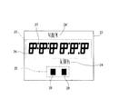
図7に本発明の実施例2である配線用遮断器形の電子式電力量計の表示手段を示し、図8に4つの表示方向に対応した状態を示す。
FIG. 7 shows display means of a circuit breaker type electronic watt-hour meter which is
図7において、22は表示手段であり、計量表示部23と計量単位表示部24,24’と動作表示部25とを有する。計量表示部23の主要部は、二つの液晶表示7セグメントが4セグメントの共用によりカギ状をなす液晶表示セグメント群26を、左右方向に一列に配列することによって形成される。27は計量表示部23の小数点表示用の液晶表示セグメントである。なお、図7は全てのセグメントを表示状態(全点灯状態)としたものである。
In FIG. 7,
計量単位表示部24’は計量単位表示部24に対して上下方向に逆さまになっているものである。動作表示部25は動作を表示するための液晶表示セグメント28と無計量を表示するための液晶表示セグメント29からなる。
The weighing
図8においては、31は電子式電力量計の筐体、32は電源側端子ねじ、33は負荷側端子ねじである。34は銘板、35は表示方向切替スイッチである。図8には表示方向に対応する表示手段22の4つの表示パターン(Tタイプ、Rタイプ、Bタイプ、Lタイプ)が示されている。これから分かるように、RタイプおよびLタイプでは液晶表示7セグメントは上下方向に一列に並んで計量値を表示する。また、表示方向によって表示状態が変化するのは、計量表示部23と計量単位表示部24,24’のみであり、動作表示部25の表示状態は変化しない。
In FIG. 8, 31 is a housing of an electronic watt-hour meter, 32 is a power supply side terminal screw, and 33 is a load side terminal screw.
本発明は電子式電力量計のみならず、表示方向を機器本体の設置方向に合わせることが望ましい、主として数字を表示する電流計、タイムスイッチなどの機器の表示装置として適用することができる。 The present invention can be applied not only to electronic watt-hour meters but also to display devices for devices such as ammeters, time switches, etc., which mainly display numbers, in which the display direction is preferably aligned with the installation direction of the device body.
1,31 電子式電力量計の筐体
2,32 電源側端子ねじ
3,33 負荷側端子ねじ
5,22 表示手段
6,35 表示方向切替スイッチ
7〜10 表示パターン
11 液晶表示7セグメント
12〜15 液晶表示セグメント
16 記憶手段
17 表示方向判定手段
18 表示方向切替手段
19,23 計量表示部
20,24,24’ 計量単位表示部
21,25 動作表示部
26 液晶表示セグメント群
DESCRIPTION OF
Claims (5)
5. The display device with a 4-display direction switching function according to claim 1, wherein each of the first to fourth display patterns includes an operation display unit for displaying an operation.
Priority Applications (1)
| Application Number | Priority Date | Filing Date | Title |
|---|---|---|---|
| JP2006080087A JP2007256559A (en) | 2006-03-23 | 2006-03-23 | Display device with four-display-direction switching function |
Applications Claiming Priority (1)
| Application Number | Priority Date | Filing Date | Title |
|---|---|---|---|
| JP2006080087A JP2007256559A (en) | 2006-03-23 | 2006-03-23 | Display device with four-display-direction switching function |
Publications (1)
| Publication Number | Publication Date |
|---|---|
| JP2007256559A true JP2007256559A (en) | 2007-10-04 |
Family
ID=38630868
Family Applications (1)
| Application Number | Title | Priority Date | Filing Date |
|---|---|---|---|
| JP2006080087A Pending JP2007256559A (en) | 2006-03-23 | 2006-03-23 | Display device with four-display-direction switching function |
Country Status (1)
| Country | Link |
|---|---|
| JP (1) | JP2007256559A (en) |
Cited By (1)
| Publication number | Priority date | Publication date | Assignee | Title |
|---|---|---|---|---|
| JP2009116004A (en) * | 2007-11-06 | 2009-05-28 | Yamatake Corp | Display apparatus |
Citations (5)
| Publication number | Priority date | Publication date | Assignee | Title |
|---|---|---|---|---|
| JPS58166673A (en) * | 1982-03-26 | 1983-10-01 | Mitsubishi Electric Corp | Temperature-humidity exchanger of fuel cell |
| JPS591081A (en) * | 1982-06-28 | 1984-01-06 | Nippon Steel Corp | Horizontal electroslag build-up welding method |
| JPH0720555A (en) * | 1993-07-02 | 1995-01-24 | Asahi Optical Co Ltd | Display device in finder of camera |
| JPH07334135A (en) * | 1994-06-09 | 1995-12-22 | Matsushita Electric Ind Co Ltd | Display device |
| JP2002328658A (en) * | 2001-04-27 | 2002-11-15 | Mitsubishi Electric Corp | Liquid crystal display |
-
2006
- 2006-03-23 JP JP2006080087A patent/JP2007256559A/en active Pending
Patent Citations (5)
| Publication number | Priority date | Publication date | Assignee | Title |
|---|---|---|---|---|
| JPS58166673A (en) * | 1982-03-26 | 1983-10-01 | Mitsubishi Electric Corp | Temperature-humidity exchanger of fuel cell |
| JPS591081A (en) * | 1982-06-28 | 1984-01-06 | Nippon Steel Corp | Horizontal electroslag build-up welding method |
| JPH0720555A (en) * | 1993-07-02 | 1995-01-24 | Asahi Optical Co Ltd | Display device in finder of camera |
| JPH07334135A (en) * | 1994-06-09 | 1995-12-22 | Matsushita Electric Ind Co Ltd | Display device |
| JP2002328658A (en) * | 2001-04-27 | 2002-11-15 | Mitsubishi Electric Corp | Liquid crystal display |
Cited By (2)
| Publication number | Priority date | Publication date | Assignee | Title |
|---|---|---|---|---|
| JP2009116004A (en) * | 2007-11-06 | 2009-05-28 | Yamatake Corp | Display apparatus |
| US8421712B2 (en) | 2007-11-06 | 2013-04-16 | Azbil Corporation | Display apparatus |
Similar Documents
| Publication | Publication Date | Title |
|---|---|---|
| CA2661932C (en) | Enhanced power distribution unit with self-orienting display | |
| JP4063800B2 (en) | Display panel drive device | |
| CN101412374B (en) | Display device | |
| CN101373589A (en) | Display control method used in a display apparatus, and display apparatus | |
| JP2014010263A (en) | Multi-display system | |
| CN102968971A (en) | Liquid crystal display driving method, time sequence control device and liquid crystal display device | |
| JP5325751B2 (en) | Signal operation check support device and signal operation check support method | |
| CN111028762B (en) | Display device | |
| JP2010072924A (en) | Surveillance simulation apparatus | |
| JP2007256559A (en) | Display device with four-display-direction switching function | |
| JP6353643B2 (en) | Vehicle display device | |
| JP5159379B2 (en) | Drawing display device | |
| JP2006010362A (en) | Portable measuring instrument and its display method | |
| JP5020044B2 (en) | Digital protection controller | |
| JP2004348076A (en) | Display | |
| JP2009163681A (en) | Communication equipment equipped with terminator | |
| US20220358886A1 (en) | Electrical Indicator and Method for Displaying an Electrical Value Using a Digital Display | |
| JP2009161128A (en) | Display device in industrial vehicle | |
| JP5508693B2 (en) | Display device | |
| US20230307895A1 (en) | Electric device having multiple displays, and control method therefor | |
| JP2012167934A (en) | Data preparation device, board inspection device, and data preparation method | |
| JPH1115443A (en) | Display equipment | |
| JP2010156651A (en) | Measuring device | |
| JP2001255344A (en) | Display of electronic watt-hour meter | |
| JP2001013483A (en) | Liquid crystal display device |
Legal Events
| Date | Code | Title | Description |
|---|---|---|---|
| A621 | Written request for application examination |
Free format text: JAPANESE INTERMEDIATE CODE: A621 Effective date: 20081021 |
|
| A131 | Notification of reasons for refusal |
Free format text: JAPANESE INTERMEDIATE CODE: A131 Effective date: 20110705 |
|
| A02 | Decision of refusal |
Free format text: JAPANESE INTERMEDIATE CODE: A02 Effective date: 20120207 |