JP2007251994A - Radio-frequency signal receiver - Google Patents
Radio-frequency signal receiver Download PDFInfo
- Publication number
- JP2007251994A JP2007251994A JP2007130235A JP2007130235A JP2007251994A JP 2007251994 A JP2007251994 A JP 2007251994A JP 2007130235 A JP2007130235 A JP 2007130235A JP 2007130235 A JP2007130235 A JP 2007130235A JP 2007251994 A JP2007251994 A JP 2007251994A
- Authority
- JP
- Japan
- Prior art keywords
- signal
- frequency
- microcontroller
- output signal
- carrier
- Prior art date
- Legal status (The legal status is an assumption and is not a legal conclusion. Google has not performed a legal analysis and makes no representation as to the accuracy of the status listed.)
- Pending
Links
- 238000005070 sampling Methods 0.000 claims abstract description 4
- 230000005236 sound signal Effects 0.000 abstract description 10
- 230000005540 biological transmission Effects 0.000 abstract description 6
- 238000004519 manufacturing process Methods 0.000 abstract description 3
- 238000012360 testing method Methods 0.000 abstract description 2
- 238000001514 detection method Methods 0.000 description 16
- 238000010586 diagram Methods 0.000 description 2
- 238000000034 method Methods 0.000 description 2
- 230000003321 amplification Effects 0.000 description 1
- 238000004891 communication Methods 0.000 description 1
- 238000007796 conventional method Methods 0.000 description 1
- 230000009977 dual effect Effects 0.000 description 1
- 238000001914 filtration Methods 0.000 description 1
- 238000003199 nucleic acid amplification method Methods 0.000 description 1
- 238000012545 processing Methods 0.000 description 1
- 238000001228 spectrum Methods 0.000 description 1
Images


Classifications
-
- H—ELECTRICITY
- H04—ELECTRIC COMMUNICATION TECHNIQUE
- H04B—TRANSMISSION
- H04B1/00—Details of transmission systems, not covered by a single one of groups H04B3/00 - H04B13/00; Details of transmission systems not characterised by the medium used for transmission
- H04B1/06—Receivers
- H04B1/10—Means associated with receiver for limiting or suppressing noise or interference
- H04B1/1027—Means associated with receiver for limiting or suppressing noise or interference assessing signal quality or detecting noise/interference for the received signal
-
- H—ELECTRICITY
- H03—ELECTRONIC CIRCUITRY
- H03G—CONTROL OF AMPLIFICATION
- H03G3/00—Gain control in amplifiers or frequency changers
- H03G3/20—Automatic control
- H03G3/30—Automatic control in amplifiers having semiconductor devices
- H03G3/34—Muting amplifier when no signal is present or when only weak signals are present, or caused by the presence of noise signals, e.g. squelch systems
- H03G3/342—Muting when some special characteristic of the signal is sensed which distinguishes it from noise, e.g. using speech detector
-
- H—ELECTRICITY
- H04—ELECTRIC COMMUNICATION TECHNIQUE
- H04B—TRANSMISSION
- H04B17/00—Monitoring; Testing
- H04B17/20—Monitoring; Testing of receivers
Landscapes
- Engineering & Computer Science (AREA)
- Computer Networks & Wireless Communication (AREA)
- Signal Processing (AREA)
- Physics & Mathematics (AREA)
- Electromagnetism (AREA)
- Mobile Radio Communication Systems (AREA)
- Noise Elimination (AREA)
Abstract
Description
本発明は、一般にコードレス電話の分野に関し、特に、RF搬送波の存在を示す信号を検出するマイクロコンピュータを使用する装置に関する。 The present invention relates generally to the field of cordless telephones, and more particularly to an apparatus that uses a microcomputer to detect a signal indicating the presence of an RF carrier.
コードレス電話システムは、アナログ回路を使用して、受信チャンネルにおける搬送波の無線周波(RF)電界強度を測定し、かつ搬送波検出出力ピンに表示信号を発生するのが慣例である。もし信号の強度がプリセットされた閾値レベル以上であるならば、適当な論理レベルの信号が搬送波検出出力ピンに発生する。搬送波検出出力ピンは、典型的には、周期的に論理レベルを読み取るマイクロプロセッサの入力に結合される。 It is customary for cordless telephone systems to use analog circuitry to measure the radio frequency (RF) field strength of the carrier in the receive channel and to generate a display signal at the carrier sense output pin. If the signal strength is above a preset threshold level, an appropriate logic level signal is generated at the carrier detect output pin. The carrier detect output pin is typically coupled to the input of a microprocessor that periodically reads the logic level.
搬送波検出信号から集められる情報にはいくつかの用途がある。例えば、基本ユニット内のマイクロプロセッサは、この情報を使用して、ハンドユニットが範囲外にあるかどうかを確かめる。あるいは、基本ユニットまたはハンドユニット内のマイクロプロセッサはこの情報を使用して、ある特定のチャンネルが占有されているかどうかを確かめることができる。例えば、本願発明の従来技術としては、特開昭61−062237号公報(特許文献1)や、特開平05−090980号公報(特許文献2)などがあり、特開昭61−062237号公報(特許文献1)には、ノイズレベルに基づき搬送波の存在を判定する判定回路が記載されており、特開平05−090980号公報(特許文献2)には、音声スケルチ回路に含まれる帯域フィルタと低域・高域フィルタとが信号成分とノイズ成分をフィルタリングし、その結果、ノイズ成分が高ければ入力信号はスピーカに出力されない回路構成が、記載されている。
都合の悪いことに、特定の閾値で正確なトリガを確実にするためには、製造工程の間に、アナログ搬送波検出回路の調節を行わなければならない。この調節作業は困難になりがちであり、時間がかかり、RF搬送波の検出をしばしば信頼できないものにする。 Unfortunately, to ensure accurate triggering at a particular threshold, adjustments to the analog carrier detection circuit must be made during the manufacturing process. This adjustment task can be difficult, time consuming, and often makes the detection of the RF carrier unreliable.
無線周波(RF)信号の受信機は無線周波信号を受け取る入力を備えており、無線周波信号には不在期間がある。信号検出回路は無線周波信号に応答して出力信号を発生する。出力信号は、RF信号が存在する場合、ベースバンド信号であり、RF信号の不在の場合には雑音信号である。利用回路はベースバンド信号を受け取りそして使用し、マイクロコンピュータ回路は受信機を制御する。 A receiver of a radio frequency (RF) signal has an input for receiving the radio frequency signal, and the radio frequency signal has an absence period. The signal detection circuit generates an output signal in response to the radio frequency signal. The output signal is a baseband signal when an RF signal is present, and a noise signal when no RF signal is present. The utilization circuit receives and uses the baseband signal, and the microcomputer circuit controls the receiver.
マイクロコンピュータは出力信号を受け取り、該出力信号を周期的にサンプリングし、該出力信号の周波数成分を調べる。マイクロコンピュータは少なくとも1つの予め定められた周波数の閾値を使用して、出力信号に含まれている周波数が前記周波数の閾値よりも高くなければ、RF信号が存在すると判定し、出力信号に含まれている周波数が前記周波数の閾値よりも高い周波数であれば、RF信号が不在であると判定する。 The microcomputer receives the output signal, periodically samples the output signal, and examines the frequency component of the output signal. The microcomputer uses at least one predetermined frequency threshold to determine that the RF signal is present if the frequency included in the output signal is not higher than the frequency threshold and is included in the output signal. If the frequency is higher than the frequency threshold, it is determined that the RF signal is absent.
図に示す実施例では、2つの所定の周波数の閾値、高周波閾値と低周波閾値、が使用される。マイクロコンピュータは、出力信号の周波数成分を判定するために、出力信号を周期的にサンプリングして計数値を累算し、出力信号のパルス幅を測定する。マイクロコンピュータは、出力信号に含まれている周波数が低周波閾値よりも高くなければRF信号が存在していると判定し、出力信号に含まれている周波数が高周波閾値よりも高い周波数であればRF信号は不在であると判定する。また、出力信号に含まれている周波数が低周波閾値よりも高く高周波閾値よりも低ければ、マイクロコンピュータはRF信号が不在であると判定する。判定は、計数値が予め定められた値に達した時に行なわれる。高周波閾値はサンプリング速度によって決まるが、その実際の値は、音声範囲にある最高周波数よりも高くさえあれば、厳密なものではない。 In the illustrated embodiment, two predetermined frequency thresholds are used, a high frequency threshold and a low frequency threshold. In order to determine the frequency component of the output signal, the microcomputer periodically samples the output signal, accumulates the count value, and measures the pulse width of the output signal. The microcomputer determines that the RF signal exists unless the frequency included in the output signal is higher than the low frequency threshold, and if the frequency included in the output signal is higher than the high frequency threshold. It is determined that the RF signal is absent. If the frequency included in the output signal is higher than the low frequency threshold and lower than the high frequency threshold, the microcomputer determines that the RF signal is absent. The determination is made when the count value reaches a predetermined value. The high frequency threshold is determined by the sampling rate, but its actual value is not exact as long as it is higher than the highest frequency in the speech range.
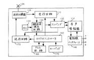
図1に関して述べると、従来技術として知られるコードレス電話100は、アンテナ106から無線周波(RF)信号を受け取り、かつアンテナ106にRF信号を供給するために、送受切換器105を含む。送受切換器105は、Soshin Electric社が製作したDPX46/49−B10型送受切換器である。送受切換器105から受け取られた信号は、検波、処理および増幅のために受信回路110に供給される。
Referring to FIG. 1, a cordless telephone 100 known in the prior art includes a
受信回路110は、ベースバンド音声信号を、スペクトル伸張のためにコンパンダ(compander)120に供給し、コンパンダ120はこの音声信号を音声増幅器130に供給する。音声増幅器130は増幅された音声信号を、電話線インタフェース装置140を介して、電話回路網のチップ(T)端子とリング(R)端子に供給する。
The receiving circuit 110 supplies the baseband audio signal to a
入来する電話信号は、電話線インタフェース装置140により受け取られ、音声増幅器130を介してコンパンダ120に供給される。コンパンダ120は音声信号の振幅を圧縮して雑音排除能力を増加させ、圧縮された信号を送信回路175に供給する。送信回路175は音声信号でRF搬送波を変調し、RF信号を送受切換器105に供給し、アンテナ106を介して送信する。
Incoming telephone signals are received by telephone
電話回路網へのインタフェーシング、ダイヤル操作、チャンネルの選択、およびコードレス電話装置のハンドユニット(図示せず)による通信は、マイクロコントローラ160の制御の下にある。マイクロコントローラ160は、マイクロプロセッサか、マイクロコンピュータかまたは専用のコントローラ集積回路である。マイクロコンピュータ160は、周波数選択のために位相ロックループ(PLL)回路165を制御し、キーボードを介して使用者が入力するデータを受け取る。
Interfacing to the telephone network, dialing, channel selection, and communication by a cordless telephone device hand unit (not shown) are under the control of the
範囲外の警告を与えるような、或る目的のために、RF搬送波信号を検出することが要求される。受信回路110は受け取った信号の一部を搬送波検出回路150に供給し、回路150は、RF搬送波の存在を表示する信号を発生する。搬送波検出回路150はアナログ回路であって、受信チャンネルにおける搬送波のRF電界強度を表わす信号を測定する。搬送波検出回路150により発生される搬送波検出信号はマイクロコントローラ160の入力に供給され、コントローラ160はこの信号を、或る特定のチャンネルがまだ使用されていないことを示すものとして、頼りにする。
For some purposes, such as giving out-of-range warnings, it is required to detect the RF carrier signal. The receiving circuit 110 supplies a portion of the received signal to the
搬送波検出回路150は、関連する調節装置155(通常は、ポテンシオメータ)を備え、これは工場で行われるアラインメント作業の間に調節されなければならない。
The
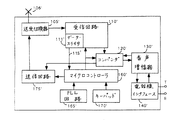
図2は本発明が組み込まれているコードレス電話装置の基本ユニットを示す。図2で、図1の要素と同じ様な番号の付いている要素は同じ機能を果たすものであり、ふたたび説明する必要はない。図2は搬送波検出回路を含まず、搬送波検出調節装置も含まない。すなわち、図2は図1の要素150および155に対応する要素を含んでいないことに注目されたい。
FIG. 2 shows the basic unit of a cordless telephone device incorporating the present invention. In FIG. 2, elements numbered similar to those in FIG. 1 serve the same function and need not be described again. FIG. 2 does not include a carrier wave detection circuit and does not include a carrier wave detection adjustment device. That is, it should be noted that FIG. 2 does not include elements corresponding to
受信回路110′により発生され検出されたベースバンド音声信号の周波数成分をマイクロコントローラ160′に検査させることにより、搬送波検出機能はマイクロコントローラ160′によって実行できることがここに認識される。受信回路110′はデータ・スライサ回路111′を含み、回路111′はベースバンド信号の一部を受け取り、それを予め定められる振幅レベルでスライスし、2進信号を発生する。データ・スライサ111′はこの2進信号を、ライン115′を介して、マイクロコントローラ160′に直接供給する。図3のaは、RF搬送波の不在の時にデータ・スライサ111′が受け取るベースバンド信号の中に存在するであろう、帯域制限された白色雑音を表わしている波形を簡略化して示す。図3のaの波形は、音声信号の周波数範囲よりも一般に高い周波数を有するランダム雑音パルスを含んでいる。図3のbは、データをスライスしたあとの、図3のaの波形を簡略化して示す。図3のbの波形は、RF搬送波の不在の時にライン115′に存在するであろう典型的な信号である。 It will now be appreciated that the carrier detection function can be performed by the microcontroller 160 'by having the microcontroller 160' examine the frequency components of the baseband audio signal generated and detected by the receiver circuit 110 '. The receiving circuit 110 'includes a data slicer circuit 111', which receives a portion of the baseband signal and slices it at a predetermined amplitude level to generate a binary signal. Data slicer 111 'provides this binary signal directly to microcontroller 160' via line 115 '. FIG. 3a shows a simplified waveform representing band-limited white noise that may be present in the baseband signal received by the data slicer 111 'in the absence of an RF carrier. The waveform of FIG. 3a includes random noise pulses having a frequency generally higher than the frequency range of the audio signal. FIG. 3b shows a simplified waveform of FIG. 3a after slicing the data. The waveform of FIG. 3b is a typical signal that would be present on line 115 'in the absence of an RF carrier.
人間の音声は1KHzの回りに集まる周波数を呈する傾向があり、会話が途切れることで生じる沈黙のため、比較的長い期間信号が全く無くなる。従って、図3のcの簡略化された波形は、図3のbに示すランダム雑音よりも周波数の低い(すなわち、パルス幅の長い)信号を示す。マイクロコントローラ160′は、雑音が存在しているか存在していないか(これは、それぞれRF搬送波が存在していないか存在しているかを示す)を判定するのに充分なほど急速に、ライン115′の信号をサンプリングできることがここに認識される。これに関して注目されるのは、マイクロコントローラ160′は、2重トーン多周波トーン(DTMFトーン)を発生する目的で118マイクロ秒ごとに中断されることである。118マイクロ秒の間隔でサンプリングすることにより、マイクロコントローラ160′は約8.5KHzまで音声周波数を識別することができる。 Human speech tends to exhibit frequencies that gather around 1 KHz, and there is no signal at all for a relatively long period of time due to the silence that occurs when the conversation is interrupted. Thus, the simplified waveform of FIG. 3c shows a signal with a lower frequency (ie, a longer pulse width) than the random noise shown in FIG. 3b. Microcontroller 160 'will quickly and sufficiently fast to determine whether noise is present or not (which indicates whether an RF carrier is present or absent, respectively). It will be recognized here that the 'signal can be sampled. It is noted in this regard that the microcontroller 160 'is interrupted every 118 microseconds for the purpose of generating a dual tone multifrequency tone (DTMF tone). By sampling at 118 microsecond intervals, the microcontroller 160 'can identify voice frequencies up to about 8.5 KHz.
通常の動作において、マイクロコントローラ160′はベースバンド信号ストリームを監視して、受信されたアナログ音声信号に伴うディジタル・データを検出する。本発明は、受信された音声信号に含まれる白色雑音に応答して“雑音エネルギ”カウンタの値を変化させる、周波数濾波アルゴリズムを含む。もし雑音エネルギ・カウンタの計数値が所定の値を超えると、現在選択されている受信チャンネルに搬送波が存在しないという判定が行なわれる。 In normal operation, the microcontroller 160 'monitors the baseband signal stream and detects digital data associated with the received analog audio signal. The present invention includes a frequency filtering algorithm that changes the value of a “noise energy” counter in response to white noise contained in the received speech signal. If the count value of the noise energy counter exceeds a predetermined value, a determination is made that no carrier is present in the currently selected receive channel.
搬送波検出機能を実行するマイクロコントローラ160′の制御プログラムの関係する部分は、図4のフローチャートを参照することにより最もよく説明される。ステップ300で、ルーチンに入り、ステップ305に進み、ここでライン115′に存在する音声信号がサンプリングされる。次に、ルーチンはステップ310に進み、ここでカウンタWIDTHの値が検査され、WIDTHの値が、最高音声周波数よりも高く、所定の高周波閾値以下であるかどうか調べられる。もしそうであれば、WIDTHの値は高い音声周波数(すなわち、白色雑音)の検出を示している。計数値が高い音声周波数が含まれていることを示していなければ、ステップ315で検査され、検出されたパルス幅が所定の低周波閾値、例えば、1KHz以上の周波数を示しているかどうか確かめられる(上述したように、人間の音声は周波数1KHzの周囲に集まる傾向がある)。もし検出された周波数が1KHz以下であれば、長いパルス幅(すなわち、低い音声周波数)が検出されており、この状態は音声および/または沈黙を示しており、ステップ320でルーチンから出て、いつものように音声信号の復号化を続ける。
The relevant part of the control program of the microcontroller 160 'that performs the carrier detection function is best explained by referring to the flowchart of FIG. At
もし含まれている周波数が高いのか(すなわち、雑音)それとも低いのか(すなわち、音声)はっきりしなければ、ルーチンはステップ325に進み、周波数が或る最低値に等しいかどうか調べられるために、カウンタ WN_ENERGY(すなわち、白色雑音エネルギ)が検出される。もし等しければ、NO_CARRIER(搬送波無い)フラグは除去され(ステップ330)、搬送波の存在を示す。そしてステップ335でルーチンから出る。WN_ENERGYは、もし最小値になっていなければ、より長いパルス幅(すなわち、より低い周波数)が検出されたので、ステップ328でデクリメントされる。ステップ350でWN_ENERGYの低い方の値を検査して、その値が所定の閾値を超えているかどうか調べる。もし超えていれば、ステップ355でNO_CARRIERフラグが設定される。超えていなければ、ステップ330でNO_CARRIERフラグは除去される。いずれの場合も、ステップ335で、ルーチンはRETURN命令によりルーチンから出る。
If it is not clear whether the included frequency is high (i.e. noise) or low (i.e. speech), the routine proceeds to step 325 and the counter is checked to see if the frequency is equal to some minimum value. WN_ENERGY (ie, white noise energy) is detected. If they are equal, the NO_CARRIER flag is removed (step 330), indicating the presence of a carrier. Step 335 then exits the routine. WN_ENERGY is decremented in
もしステップ310で、高い音声周波数が存在するという判定が行われると、YES路を通ってステップ340に進む。ここで、WN_ENERGYの成分が検査され、最大値になっているか調べられる。最大値になっていれば、YES路を取ってステップ355に進み、NO_CARRIERフラグが設定され、ルーチンから出る。WN_ENERGYは、もし最大値になっていなければ、高い周波数が検出されたので、ステップ345でインクリメントされる。ステップ350で、WN_ENERGYの高い方の値を検査して、所定の閾値を超えているか調べる。もし超えていれば、ステップ355でNO_CARRIERフラグが設定される。超えていなければ、ステップ330でNO_CARRIERフラグは除去される。いずれの場合にも、ステップ335で、RETURN命令によりルーチンから出る。
If it is determined in
従って、コードレス電話環境に役立つ(しかしこれだけに限られない)、マイクロコントローラを基礎とする搬送波検出システムが開示された。分かり易くするために、基本ユニットだけを示すが、本発明はコードレス電話ハンドユニットにも同様に応用できる。有利なことに、本発明を使用すると、個別搬送波検出回路およびそれに関連する調節装置を排除することにより、信頼性が改善される。更に、必要とされる部品の数が少なくなり、組み立ておよび試験が簡単になるので、製造コストが低減される。 Accordingly, a microcontroller-based carrier detection system has been disclosed that is useful for (but not limited to) a cordless telephone environment. For simplicity, only the basic unit is shown, but the invention is equally applicable to a cordless telephone hand unit. Advantageously, the use of the present invention improves reliability by eliminating the separate carrier detection circuit and its associated adjustment device. In addition, manufacturing costs are reduced because fewer parts are required and assembly and testing are simplified.
“マイクロコントローラ”および“マイクロコンピュータ”という用語は互いに交換して使用することができ、マイクロプロセッサ、専用制御集積回路などを含む。 The terms “microcontroller” and “microcomputer” can be used interchangeably and include a microprocessor, a dedicated control integrated circuit, and the like.
100 コードレス電話装置
105 送受切換器
106 アンテナ
110 受信回路
111′ データ・スライサ
120 コンパンダ
130 音声増幅器
140 電話線インタフェース
150 搬送波検出回路
155 調節装置
160 マイクロコントローラ
165 PLL(位相固定ループ)回路
170 キーパッド
175 送信回路
DESCRIPTION OF SYMBOLS 100
Claims (1)
不在期間のある無線周波数信号を受信する入力端と、
前記無線周波数信号に応答して、前記入力端に結合されて出力信号を発生する検波回路であって、前記出力信号は、前記無線周波数信号が存在するときはベースバンド信号であり、前記無線周波数信号が存在しないときは雑音信号である、前記検波回路と、
前記ベースバンド信号を受信し利用する利用回路と、
前記無線周波数信号受信機を制御するマイクロコンピュータ回路と、
からなり、
前記マイクロコンピュータ回路は、
a)前記出力信号を受信するように結合され、前記出力信号を周期的にサンプリングして、前記出力信号の周波数成分を判定する手段と、
b)前記出力信号の前記周波数成分が所定の低周波数閾値以下である場合に無線周波数信号が存在することを示す手段と、
c)前記出力信号の前記周波数成分が所定の高周波数閾値を超えている場合に無線周波数信号が不在であることを示す手段と、
を含む、前記無線周波数信号受信機。 In radio frequency signal receiver,
An input for receiving a radio frequency signal with an absence period;
A detector circuit coupled to the input to generate an output signal in response to the radio frequency signal, wherein the output signal is a baseband signal when the radio frequency signal is present; The detector circuit, which is a noise signal when no signal is present;
A circuit for receiving and using the baseband signal;
A microcomputer circuit for controlling the radio frequency signal receiver;
Consists of
The microcomputer circuit includes:
a) coupled to receive the output signal, periodically sampling the output signal to determine a frequency component of the output signal;
b) means for indicating that a radio frequency signal is present when the frequency component of the output signal is below a predetermined low frequency threshold;
c) means for indicating that no radio frequency signal is present when the frequency component of the output signal exceeds a predetermined high frequency threshold;
The radio frequency signal receiver comprising:
Applications Claiming Priority (1)
| Application Number | Priority Date | Filing Date | Title |
|---|---|---|---|
| US17135393A | 1993-12-21 | 1993-12-21 |
Related Parent Applications (1)
| Application Number | Title | Priority Date | Filing Date |
|---|---|---|---|
| JP6340627A Division JPH07202796A (en) | 1993-12-21 | 1994-12-20 | Radio frequency signal receiver |
Publications (1)
| Publication Number | Publication Date |
|---|---|
| JP2007251994A true JP2007251994A (en) | 2007-09-27 |
Family
ID=22623429
Family Applications (2)
| Application Number | Title | Priority Date | Filing Date |
|---|---|---|---|
| JP6340627A Pending JPH07202796A (en) | 1993-12-21 | 1994-12-20 | Radio frequency signal receiver |
| JP2007130235A Pending JP2007251994A (en) | 1993-12-21 | 2007-05-16 | Radio-frequency signal receiver |
Family Applications Before (1)
| Application Number | Title | Priority Date | Filing Date |
|---|---|---|---|
| JP6340627A Pending JPH07202796A (en) | 1993-12-21 | 1994-12-20 | Radio frequency signal receiver |
Country Status (8)
| Country | Link |
|---|---|
| US (1) | US5864750A (en) |
| EP (1) | EP0660536B1 (en) |
| JP (2) | JPH07202796A (en) |
| KR (1) | KR100355855B1 (en) |
| CN (1) | CN1071983C (en) |
| DE (1) | DE69434275T2 (en) |
| MY (1) | MY114515A (en) |
| SG (1) | SG64868A1 (en) |
Families Citing this family (2)
| Publication number | Priority date | Publication date | Assignee | Title |
|---|---|---|---|---|
| US7127448B1 (en) * | 2000-04-26 | 2006-10-24 | Oracle International Corporation | Reforming queries to selectively audit accesses to rows within a relational database |
| US7373554B2 (en) * | 2004-09-24 | 2008-05-13 | Oracle International Corporation | Techniques for automatic software error diagnostics and correction |
Family Cites Families (16)
| Publication number | Priority date | Publication date | Assignee | Title |
|---|---|---|---|---|
| US3437937A (en) * | 1966-08-08 | 1969-04-08 | Wilcox Electric Co Inc | Digital squelch system |
| US3633112A (en) * | 1970-09-28 | 1972-01-04 | Collins Radio Co | Digital audio squelch |
| US3902123A (en) * | 1973-11-30 | 1975-08-26 | Cincinnati Electronics Corp | Digital circuit for determining if signal source consists primarily of noise or contains information |
| JPS61112435A (en) * | 1984-11-06 | 1986-05-30 | Nec Corp | Carrier detection circuit |
| GB2212032A (en) * | 1987-10-30 | 1989-07-12 | Philips Nv | Controlled csma packet switching system |
| GB2217150B (en) * | 1988-03-05 | 1992-04-01 | Racal Tacticom Systems Ltd | Frequency responsive systems & methods |
| JPH02186723A (en) * | 1988-08-25 | 1990-07-23 | Nec Corp | Receiver |
| US5031233A (en) * | 1989-07-11 | 1991-07-09 | At&E Corporation | Single chip radio receiver with one off-chip filter |
| US5101509A (en) * | 1990-09-14 | 1992-03-31 | Ford Motor Company | Rf filter alignment using digital processor clock |
| JPH04216226A (en) * | 1990-12-17 | 1992-08-06 | Tokyo Electric Co Ltd | Received signal detector |
| JPH04247723A (en) * | 1991-02-01 | 1992-09-03 | Fujitsu Ten Ltd | Detector for radio communication wave |
| US5349701A (en) * | 1992-01-15 | 1994-09-20 | Motorola, Inc. | Method and apparatus for broken link detect using audio energy level |
| JPH05292006A (en) * | 1992-04-07 | 1993-11-05 | Matsushita Electric Ind Co Ltd | Cordless telephone system |
| JPH05347582A (en) * | 1992-06-15 | 1993-12-27 | Funai Electric Co Ltd | Carrier detecting method |
| US5732337A (en) * | 1995-08-10 | 1998-03-24 | Ford Motor Company | Reconfigurable mixer-filter-decimator |
| US5715282A (en) * | 1996-05-08 | 1998-02-03 | Motorola, Inc. | Method and apparatus for detecting interference in a receiver for use in a wireless communication system |
-
1994
- 1994-12-14 EP EP94119710A patent/EP0660536B1/en not_active Expired - Lifetime
- 1994-12-14 SG SG1996002110A patent/SG64868A1/en unknown
- 1994-12-14 DE DE69434275T patent/DE69434275T2/en not_active Expired - Lifetime
- 1994-12-19 KR KR1019940034995A patent/KR100355855B1/en not_active IP Right Cessation
- 1994-12-20 CN CN94113250A patent/CN1071983C/en not_active Expired - Fee Related
- 1994-12-20 MY MYPI94003425A patent/MY114515A/en unknown
- 1994-12-20 JP JP6340627A patent/JPH07202796A/en active Pending
-
1997
- 1997-10-23 US US08/998,938 patent/US5864750A/en not_active Expired - Lifetime
-
2007
- 2007-05-16 JP JP2007130235A patent/JP2007251994A/en active Pending
Also Published As
| Publication number | Publication date |
|---|---|
| EP0660536A2 (en) | 1995-06-28 |
| US5864750A (en) | 1999-01-26 |
| DE69434275T2 (en) | 2005-06-30 |
| CN1071983C (en) | 2001-09-26 |
| EP0660536B1 (en) | 2005-02-16 |
| SG64868A1 (en) | 1999-05-25 |
| EP0660536A3 (en) | 1995-12-27 |
| MY114515A (en) | 2002-11-30 |
| KR100355855B1 (en) | 2002-12-16 |
| CN1114491A (en) | 1996-01-03 |
| JPH07202796A (en) | 1995-08-04 |
| DE69434275D1 (en) | 2005-03-24 |
Similar Documents
| Publication | Publication Date | Title |
|---|---|---|
| EP0738445B1 (en) | Clear channel selection system for a cordless telephone | |
| KR910004059B1 (en) | Radio telephone system | |
| US4663765A (en) | Data muting method and apparatus for audo-digital communications systems | |
| EP0153125A2 (en) | Tone detection apparatus for use in a telephone system | |
| US5598431A (en) | Method and apparatus for signal quality detection in a communication system | |
| US4525868A (en) | Interference wave detection circuit for use in radio receiver | |
| KR20000001839A (en) | Abnormality detecting method of transceiver at base station and device thereof | |
| JP2007251994A (en) | Radio-frequency signal receiver | |
| KR20040078147A (en) | Fast settling data slicer comprising a low-pass filter with switchable cut-off frequency and a notch-filter | |
| JPH11163748A (en) | Tone signal detection circuit | |
| US6055421A (en) | Carrier squelch method and apparatus | |
| US6744748B1 (en) | Method and apparatus for monitoring errors in a wireless transceiver | |
| KR100247040B1 (en) | Apparatus and method for automatically cutting off call | |
| US4984294A (en) | Radio communications device incorporating channel guard decode and priority channel scanning | |
| KR0154694B1 (en) | Radio telephone | |
| JPS5452408A (en) | Radiotelephone set | |
| KR0169323B1 (en) | Dial tone generating circuit in a telephone | |
| JPH05292017A (en) | Cordless telephone set | |
| JPH0255427A (en) | Squelch circuit | |
| JP2000232421A (en) | Radio receiver | |
| KR930015397A (en) | Call radius detection alarm system of wireless telephone using received field strength indication | |
| JPH0226133A (en) | Receiving wave interference detector | |
| KR20000020589A (en) | Apparatus for detecting call connection according to originating call in telecommunication terminal and method therefor | |
| JPH1198235A (en) | Handsfree unit for portable telephone | |
| JPH04267660A (en) | Idle channel discrimination method |
Legal Events
| Date | Code | Title | Description |
|---|---|---|---|
| RD05 | Notification of revocation of power of attorney |
Free format text: JAPANESE INTERMEDIATE CODE: A7425 Effective date: 20080318 |
|
| RD04 | Notification of resignation of power of attorney |
Free format text: JAPANESE INTERMEDIATE CODE: A7424 Effective date: 20080415 |
|
| A131 | Notification of reasons for refusal |
Free format text: JAPANESE INTERMEDIATE CODE: A131 Effective date: 20091118 |
|
| A601 | Written request for extension of time |
Free format text: JAPANESE INTERMEDIATE CODE: A601 Effective date: 20100210 |
|
| A602 | Written permission of extension of time |
Free format text: JAPANESE INTERMEDIATE CODE: A602 Effective date: 20100216 |
|
| A02 | Decision of refusal |
Free format text: JAPANESE INTERMEDIATE CODE: A02 Effective date: 20100728 |