JP2007201283A - Electronic control device and casing therefor - Google Patents

Electronic control device and casing therefor Download PDF

Info

Publication number
JP2007201283A
JP2007201283A JP2006019624A JP2006019624A JP2007201283A JP 2007201283 A JP2007201283 A JP 2007201283A JP 2006019624 A JP2006019624 A JP 2006019624A JP 2006019624 A JP2006019624 A JP 2006019624A JP 2007201283 A JP2007201283 A JP 2007201283A
Authority
JP
Japan
Prior art keywords
control device
electronic control
housing
electronic
electronic component
Prior art date
Legal status (The legal status is an assumption and is not a legal conclusion. Google has not performed a legal analysis and makes no representation as to the accuracy of the status listed.)
Pending
Application number
JP2006019624A
Other languages
Japanese (ja)
Inventor
Satoru Yamauchi
知 山内
Toshiki Kobayashi
俊樹 小林
Current Assignee (The listed assignees may be inaccurate. Google has not performed a legal analysis and makes no representation or warranty as to the accuracy of the list.)
Denso Corp
Original Assignee
Denso Corp
Priority date (The priority date is an assumption and is not a legal conclusion. Google has not performed a legal analysis and makes no representation as to the accuracy of the date listed.)
Filing date
Publication date
Application filed by Denso Corp filed Critical Denso Corp
Priority to JP2006019624A priority Critical patent/JP2007201283A/en
Publication of JP2007201283A publication Critical patent/JP2007201283A/en
Pending legal-status Critical Current

Links

Images

Landscapes

  • Electrical Control Of Air Or Fuel Supplied To Internal-Combustion Engine (AREA)
  • Cooling Or The Like Of Electrical Apparatus (AREA)
  • Cooling Or The Like Of Semiconductors Or Solid State Devices (AREA)

Abstract

<P>PROBLEM TO BE SOLVED: To provide an electronic control device which can increase a heat radiation efficiency by shortening a heat radiation path from a casing to a vehicle, and to provide a casing for the electronic control device. <P>SOLUTION: The electronic control device 100 is mounted to a member such as the side wall 200 of an engine room by thermal conductive brackets 40. The electronic control device 100 comprises a board 21 having a heat generating element 22a or the like mounted thereon and a casing 10 for accommodating the board 21. The casing 10 has mounts 14 for mounting of the brackets 40 thereon. The mounts 14 are provided to be projected inwardly of the casing 10 at a position corresponding to the heat generating element 14. <P>COPYRIGHT: (C)2007,JPO&INPIT

Description

本発明は、発熱する電子部品が実装された回路基板を放熱材料からなる筐体内に収容してなる電子制御装置及び電子制御装置の筐体に関するものである。   The present invention relates to an electronic control device in which a circuit board on which a heat generating electronic component is mounted is housed in a housing made of a heat dissipation material, and a housing of the electronic control device.

従来、車両等に搭載される電子制御装置は、筐体内に電子部品が実装された回路基板を収容することにより構成されており、この電子部品の中には、例えばパワートランジスタのように発熱が大きい部品が含まれている。従って、電子部品から発生する熱を外部へ放熱する必要がある。   2. Description of the Related Art Conventionally, an electronic control device mounted on a vehicle or the like is configured by housing a circuit board on which an electronic component is mounted in a housing, and the electronic component generates heat such as a power transistor, for example. Big parts are included. Therefore, it is necessary to radiate the heat generated from the electronic component to the outside.

例えば本出願人は、特許文献1において、回路基板を収容する筐体に突出部を設けることによって放熱板として利用し、電子部品が搭載された回路基板を、柔軟性を有する(粘弾性が低い)放熱材を介して筐体へ熱的に接続する放熱構造を開示している。
特開2003−289191号公報
For example, in the case of Patent Document 1, the present applicant uses a circuit board on which electronic components are mounted as a heat sink by providing a protrusion on a housing that accommodates a circuit board, and has flexibility (low viscoelasticity). ) A heat dissipation structure that is thermally connected to the housing via a heat dissipation material is disclosed.
JP 2003-289191 A

しかしながら、特許文献1に示す電子制御装置においては、筐体を放熱板として利用すると共に、放熱剤を介して電子部品から発生する熱を外部へ放熱できるものの、筐体から被取付体(車両におけるエンジンルーム内の側壁など)への放熱までは考慮されておらず、筐体から車両への放熱経路が長くなる可能性があった。   However, in the electronic control device shown in Patent Document 1, the housing is used as a heat radiating plate, and heat generated from the electronic component can be radiated to the outside through the heat radiating agent. The heat radiation to the side wall in the engine room is not considered, and there is a possibility that the heat radiation path from the housing to the vehicle becomes long.

本発明は上記問題点に鑑み、筐体から車両への放熱経路を短くし放熱性を向上することができる電子制御装置及び電子制御装置の筐体を提供することを目的とする。   In view of the above problems, an object of the present invention is to provide an electronic control device and a housing for the electronic control device that can shorten the heat dissipation path from the housing to the vehicle and improve heat dissipation.

上記目的を達成するために請求項1に記載の電子制御装置は、熱伝導性の接続部材によって被取付体に取付けられる電子制御装置であって、電子制御装置は、発熱する電子部品が実装された回路基板と、回路基板を収容するものであり、放熱材料からなり、接続部材を取付ける取付部を有する筐体とを備え、取付部は、筐体の内側方向であり電子部品に対応する位置に突出して設けられることを特徴とするものである。   In order to achieve the above object, an electronic control device according to claim 1 is an electronic control device that is attached to a mounted body by a thermally conductive connecting member, and the electronic control device is mounted with an electronic component that generates heat. A circuit board and a housing that contains the circuit board and is made of a heat dissipation material and has a mounting portion to which a connection member is attached. The mounting portion is an inner direction of the housing and corresponds to an electronic component. It is characterized by being provided so as to protrude.

このように、電子制御装置を被取付体に取り付ける接続部材を筐体に取り付けるための取付部を筐体の内側方向であり電子部品に対応する位置に突出して設けることによって、筐体から被取付体への放熱経路を短くすることができ放熱性を向上することができる。   As described above, the mounting portion for mounting the connecting member for mounting the electronic control device on the mounted body is attached to the housing by protruding from a position corresponding to the electronic component in the inner direction of the housing. The heat dissipation path to the body can be shortened and the heat dissipation can be improved.

また、請求項2に記載の電子制御装置では、取付部は、螺子によって接続部材が取り付けられるものであり、筐体の外部から内部に貫通しない螺子穴を備えることを特徴とするものである。   According to a second aspect of the present invention, in the electronic control device according to the second aspect of the present invention, the attachment portion is a member to which the connecting member is attached by a screw, and includes a screw hole that does not penetrate from the outside to the inside of the housing.

このように、取付部に筐体の外部から内部に貫通しない螺子穴を備えることによって、防水性を向上することができる。   Thus, by providing the attachment portion with a screw hole that does not penetrate from the outside to the inside of the housing, the waterproof property can be improved.

また、請求項3に記載の電子制御装置では、取付部は、螺子穴以外を筐体を形成する放熱材料からなることを特徴とするものである。   According to a third aspect of the present invention, the mounting portion is made of a heat dissipating material that forms a casing other than the screw holes.

このように、取付部は、螺子穴以外を筐体を形成する放熱材料とすることによって、取付部の方熱経路を大きくすることができより一層放熱性を向上することができる。   As described above, by using the heat dissipating material other than the screw hole as the heat dissipating material for forming the housing, the attaching portion can increase the heat path of the attaching portion and further improve the heat dissipation.

また、請求項4に記載の電子制御装置では、取付部は、放熱フィンを備えることを特徴とするものである。   According to a fourth aspect of the present invention, in the electronic control device according to the fourth aspect of the present invention, the attachment portion includes a radiation fin.

このように、取付部に放熱フィンを備えることによって、より一層放熱性を向上することができる。   Thus, heat dissipation can be further improved by providing the mounting portion with heat dissipating fins.

また、請求項5に記載の電子制御装置では、取付部と電子部品との間に放熱部材を備えることを特徴とするものである。   According to a fifth aspect of the present invention, the electronic control device includes a heat radiating member between the mounting portion and the electronic component.

このように、取付部と電子部品との間に放熱部材を備えることによって、より一層放熱性を向上することができる。   Thus, heat dissipation can be further improved by providing a heat dissipation member between the attachment portion and the electronic component.

また、請求項6に記載の電子制御装置では、放熱部材は、柔軟性を有することを特徴とするものである。   In the electronic control device according to the sixth aspect, the heat dissipating member has flexibility.

このように、放熱部材が柔軟性を有することによって、筐体と電子部品との密着性を向上することができる。すなわち、放熱性を向上することができる。また、柔軟性を有するので、筐体と回路基板との間隔が一定でなくとも、電子部品の局部に応力が集中し、破損が生じるのを防ぐことができる。さらには、接着剤のように硬化しないため、電子部品に熱応力が加わることもない。   As described above, since the heat dissipation member has flexibility, the adhesion between the housing and the electronic component can be improved. That is, heat dissipation can be improved. Moreover, since it has flexibility, even if the distance between the housing and the circuit board is not constant, it is possible to prevent stress from being concentrated on the local part of the electronic component and causing damage. Furthermore, since it does not harden like an adhesive, thermal stress is not applied to the electronic component.

また、請求項7に記載の電子制御装置では、筐体及び回路基板のうち少なくとも一方に、この筐体と回路基板とを位置決めする位置決め部を備えるものであり、電子部品は、位置決め部の近傍に配置され、取付部は、電子部品に対応する位置に突出して設けられることを特徴とするものである。   In the electronic control device according to claim 7, at least one of the housing and the circuit board is provided with a positioning portion for positioning the housing and the circuit board, and the electronic component is located in the vicinity of the positioning portion. The mounting portion is provided to project at a position corresponding to the electronic component.

このように、電子部品を位置決め部の近傍に配置し、取付部を電子部品に対応する位置に突出して設けることによって、回路基板のそりの公差を考慮することなく放熱剤の厚みを小さく設計することができるため、放熱性をより一層向上させることができる。   In this way, by arranging the electronic component in the vicinity of the positioning portion and providing the mounting portion so as to protrude at a position corresponding to the electronic component, the thickness of the heat radiation agent is designed to be small without considering the tolerance of warping of the circuit board. Therefore, heat dissipation can be further improved.

また、取付部は、請求項8に示すように、筐体における少なくとも一つの側面の一部を含んで設けられるものである。さらに、取付部は、請求項9に示すように、筐体における回路基板に対向する対向面の一部を含んで設けられるものである。   Further, as shown in claim 8, the attachment portion is provided so as to include a part of at least one side surface of the housing. Furthermore, as shown in claim 9, the mounting portion is provided so as to include a part of the facing surface of the housing that faces the circuit board.

また、請求項10に示すように、取付部は、電子部品と対向する位置に設けられ、少なくとも電子部品における取付部との対抗面の全体を覆う形状をなすことを特徴とするものである。   According to a tenth aspect of the present invention, the attachment portion is provided at a position facing the electronic component and has a shape that covers at least the entire surface facing the attachment portion of the electronic component.

このように、取付部は、少なくとも電子部品における取付部との対抗面の全体を覆う形状をなすことによって、電子部品から生じる熱を受けることができ、より一層放熱性を向上することができる。   Thus, the attachment portion can receive heat generated from the electronic component by forming a shape that covers at least the entire surface facing the attachment portion of the electronic component, and can further improve heat dissipation.

また、電子部品としては、請求項11に示すように、表面実装型であることが好ましい。例えば、縦型(スルーホール型)の電子部品である場合、電子部品を回路基板と取付部との間に設けようとすると電子制御装置の体格が大きくなってしまう。したがって、体格を大きくすることなく縦型の電子部品を取付部に対応する位置に設けようとすると、取付部の側面に位置合せして電子部品を搭載する必要がある。しかしながら、取付部の側面と電子部品とを位置合せする場合、位置合せの精度が低下してしまうため放熱性も低下する可能性がる。しかしながら、請求項11に示すように、表面実装型の電子部品の場合、取付部と回路基板との間に設けたとしても電子制御装置の体格が大きくなることを抑制することができる。また、取付部と回路基板との間に電子部品を設ける場合は、比較的位置合せの精度がよくなるので、放熱性も向上する。   The electronic component is preferably a surface mount type as shown in claim 11. For example, in the case of a vertical (through-hole) electronic component, if the electronic component is provided between the circuit board and the mounting portion, the size of the electronic control device is increased. Therefore, if the vertical electronic component is to be provided at a position corresponding to the mounting portion without increasing the size, the electronic component needs to be mounted in alignment with the side surface of the mounting portion. However, when aligning the side surface of the mounting portion and the electronic component, the accuracy of alignment is reduced, and thus heat dissipation may be reduced. However, as shown in claim 11, in the case of the surface-mount type electronic component, even if it is provided between the mounting portion and the circuit board, it is possible to suppress the increase in the size of the electronic control device. Further, when an electronic component is provided between the mounting portion and the circuit board, the alignment accuracy is relatively improved, so that heat dissipation is improved.

また、請求項12に示すように、表面実装型の電子部品は、複数のパワートランジスタを含むものである。このように電子部品が複数のパワートランジスタを含む場合、各パワートランジスタ間の貰い熱などによって電子部品の発熱量がより多くなる。したがって、このように複数のパワートランジスタを用いる場合、取付部にて放熱経路を短くして放熱性を向上させることは特に効果的である。   According to a twelfth aspect of the present invention, the surface mount electronic component includes a plurality of power transistors. When the electronic component includes a plurality of power transistors as described above, the amount of heat generated by the electronic component is increased due to the high heat between the power transistors. Therefore, when a plurality of power transistors are used in this way, it is particularly effective to improve the heat dissipation by shortening the heat dissipation path at the mounting portion.

また、複数のパワートランジスタは、請求項13に示すように、モールドパッケージされた平板形状の集積回路であってもよい。このようにモールドパッケージされた平板形状の集積回路の場合、放熱部材を設けやすいので好ましい。   The plurality of power transistors may be a mold-packaged flat plate-shaped integrated circuit. In the case of a flat-plate integrated circuit molded and packaged in this way, a heat radiating member is easily provided, which is preferable.

また、パワートランジスタとしては、請求項14に示すように、エンジン制御に関する電気負荷に電気的に接続されるものであり、電気負荷に対して電力供給を行うものとすることができる。このようにエンジン制御に関する電気負荷に対して電力を供給するようなパワートランジスタは、比較的発熱量も多くなり、より一層放熱が必要とされる。したがって、このようなパワートランジスタを用いる場合、取付部にて放熱経路を短くして放熱性を向上させることは特に効果的である。   Further, as shown in claim 14, the power transistor is electrically connected to an electric load related to engine control, and power can be supplied to the electric load. Thus, a power transistor that supplies electric power to an electric load related to engine control has a relatively large amount of heat generation, and further heat dissipation is required. Therefore, when such a power transistor is used, it is particularly effective to shorten the heat radiation path at the mounting portion to improve the heat radiation performance.

また、請求項15に示すように、回路基板は、少なくとも入力処理及び/又は演算処理を実行する電子素子が実装されるものである場合、パワートランジスタとしては、バッテリー電圧を前記電子素子に対応する所定の電圧に降圧する降圧回路とすることができる。このように降圧回路として用いられるパワートランジスタに関しても、比較的発熱量が多くなり、より一層放熱が必要とされる。したがって、このようなパワートランジスタを用いる場合に関しても、取付部にて放熱経路を短くして放熱性を向上させることは特に効果的である。   Further, according to a fifteenth aspect of the present invention, in the case where an electronic element that executes at least input processing and / or arithmetic processing is mounted on the circuit board, the power transistor corresponds to a battery voltage corresponding to the electronic element. The step-down circuit can step down to a predetermined voltage. As described above, the power transistor used as the step-down circuit also has a relatively large amount of heat generation, and further heat dissipation is required. Therefore, even when such a power transistor is used, it is particularly effective to shorten the heat radiation path at the mounting portion to improve the heat radiation performance.

また、請求項16乃至請求項19に記載の表示装置での作用・効果に関しては、上述の請求項1乃至請求項4と同様であるため説明を省略する。また、請求項20及び請求項27に記載の表示装置での作用・効果に関しては、上述の請求項8乃至請求項15と同様であるため説明を省略する。   The operation and effect of the display device according to the sixteenth to nineteenth aspects is the same as that of the first to fourth aspects described above, and a description thereof will be omitted. The operation and effect of the display device according to claims 20 and 27 is the same as that of the above-described claims 8 to 15, and thus the description thereof is omitted.

以下、本発明の実施の形態を図に基づいて説明する。   Hereinafter, embodiments of the present invention will be described with reference to the drawings.

(実施形態)
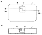
まず、本発明の実施形態について説明する。図1は、本発明における電子制御装置の概略構成を説明するための、組み付け前の状態を示す分解図である。図2は、本発明における電子制御装置の車両への組み付け状態を示す側面図である。図3は、本発明の実施形態における回路基板を説明するための図面であり、(a)は斜視図であり、(b)は表面側の平面図であり、(c)は裏面側の平面図である。図4は、本発明の実施形態における回路基板をベースに取付けた状態を示す平面図である。図5は、本発明の実施形態におけるケースを説明するための図面であり、(a)は平面図であり、(b)は短手方向の側面図であり、(c)は長手方向の側面図である。図6は、本発明の実施形態における筐体と回路基板とを組み付けた状態を説明するための図面であり、(a)は平面図、(b)は短手方向の側面図である。図7は、本発明の実施形態におけるブラケットを電子制御装置に組み付けた状態を説明するための図面であり、(a)は短手方向の側面図であり、(b)はVIIb−VIIb断面図である。なお、本実施形態に示す電子制御装置は、車両のエンジンECU(Electric Control Unit)などに適用されるものである。
(Embodiment)
First, an embodiment of the present invention will be described. FIG. 1 is an exploded view showing a state before assembly for explaining a schematic configuration of an electronic control device according to the present invention. FIG. 2 is a side view showing a state where the electronic control device according to the present invention is assembled to a vehicle. 3A and 3B are diagrams for explaining a circuit board according to an embodiment of the present invention, in which FIG. 3A is a perspective view, FIG. 3B is a plan view on the front surface side, and FIG. FIG. FIG. 4 is a plan view showing a state in which the circuit board according to the embodiment of the present invention is attached to the base. 5A and 5B are diagrams for explaining a case in the embodiment of the present invention, in which FIG. 5A is a plan view, FIG. 5B is a side view in a short direction, and FIG. 5C is a side view in a longitudinal direction. FIG. 6A and 6B are drawings for explaining a state in which the housing and the circuit board are assembled in the embodiment of the present invention, where FIG. 6A is a plan view and FIG. 6B is a side view in the short direction. 7A and 7B are diagrams for explaining a state in which the bracket according to the embodiment of the present invention is assembled to the electronic control device, wherein FIG. 7A is a side view in the short direction, and FIG. 7B is a cross-sectional view along VIIb-VIIb. It is. The electronic control device shown in the present embodiment is applied to an engine ECU (Electric Control Unit) of a vehicle.

図1に示すように、電子制御装置100は、筐体10と、この筐体10内に収容される回路基板20となどを備える。そして、この電子制御装置100は、図2に示すように、エンジンルーム壁面200(被取付体)にブラケット40(接続部材)を介してボルト50で固定される。なお、被取付体としては、エンジンルーム壁面200以外にも、エンジンルーム内における電子制御装置を入れておくECUボックスなどの壁面、エンジン、トランクルームの壁面、車室内の壁面などであってもよい。また、図2においては、電子制御装置100は、エンジンルーム壁面200の側壁に縦に固定されている状態を示したが、本発明はこれに限定されるものではなく、搭載位置に応じて適宜変更可能である。   As shown in FIG. 1, the electronic control device 100 includes a housing 10 and a circuit board 20 accommodated in the housing 10. As shown in FIG. 2, the electronic control device 100 is fixed to the engine room wall surface 200 (attachment body) with a bolt 50 via a bracket 40 (connection member). In addition to the engine room wall surface 200, the attached body may be a wall surface such as an ECU box in which an electronic control device is placed in the engine room, an engine, a wall surface of a trunk room, a wall surface of a vehicle compartment, and the like. 2 shows a state in which the electronic control unit 100 is vertically fixed to the side wall of the engine room wall surface 200. However, the present invention is not limited to this, and is appropriately set according to the mounting position. It can be changed.

回路基板20は、図3(a)〜(c)に示すように、配線パターンや配線パターン間を接続するビアホール等が形成されてなるプリント基板21(以下、単に基板とも称する)に、マイコン、パワートランジスタ、チップ抵抗、コンデンサ、クリスタル等の電子部品22を実装してなるものである。基板21の構成材料としては、熱可塑性樹脂、熱硬化性樹脂、セラミック、ガラス(例えばガラス布)と樹脂との複合体等の公知材料を適用することができる。   As shown in FIGS. 3A to 3C, the circuit board 20 includes a microcomputer, a printed circuit board 21 (hereinafter also simply referred to as a board) in which wiring patterns and via holes for connecting the wiring patterns are formed. An electronic component 22 such as a power transistor, a chip resistor, a capacitor, or a crystal is mounted. As a constituent material of the substrate 21, a known material such as a thermoplastic resin, a thermosetting resin, a ceramic, a composite of glass (for example, a glass cloth) and a resin, or the like can be applied.

また、基板21は、後ほど説明するベース12に対する位置決めを行うための位置決め穴25を備える。一方、ベース12には、この位置決め穴に対応する位置決め突起12aが設けられる。そして、基板21は、図4に示すように、この位置決め穴25とベース12の位置決め突起12aとによってベース12に位置決めされてベース12に固定される。   Moreover, the board | substrate 21 is equipped with the positioning hole 25 for performing positioning with respect to the base 12 demonstrated later. On the other hand, the base 12 is provided with positioning protrusions 12a corresponding to the positioning holes. As shown in FIG. 4, the substrate 21 is positioned on the base 12 and fixed to the base 12 by the positioning holes 25 and the positioning projections 12 a of the base 12.

電子部品22は、図3(b)に示すように、基板21の一方の面(以下、表面とも称する)に実装されると共に、図3(c)に示すように、基板21の他方の面(以下、裏面とも称する)にも実装されてもよい。また、電子部品22には、例えばパワートランジスタといった動作によって過度に発熱する発熱素子22aが含まれている。この発熱素子22aが、特許請求の範囲で示す発熱する電子部品に相当する。この発熱素子22aは、接着剤23を介して基板21に実装さ、接着材23が形成される面とは半対面に放熱剤24を備える。この放熱剤24に関しては、後ほど説明する。   The electronic component 22 is mounted on one surface (hereinafter also referred to as a surface) of the substrate 21 as shown in FIG. 3B, and the other surface of the substrate 21 as shown in FIG. (Hereinafter also referred to as the back surface). Further, the electronic component 22 includes a heating element 22a that generates excessive heat by an operation such as a power transistor. The heating element 22a corresponds to an electronic component that generates heat in the claims. The heat generating element 22a is mounted on the substrate 21 via an adhesive 23, and includes a heat radiating agent 24 on a surface facing the surface on which the adhesive 23 is formed. The heat radiation agent 24 will be described later.

また、発熱素子22aとしては、表面実装型(SMD)であることが好ましい。例えば、縦型(スルーホール型)の発熱素子(トランジスタなど)である場合、縦型の発熱素子を基板21と取付部14との間に設けようとすると電子制御装置100の体格が大きくなってしまう。したがって、電子制御装置100の体格を大きくすることなく縦型の発熱素子を取付部14に対応する位置に設けようとすると、取付部14の側面に位置合せして縦型の発熱素子を搭載する必要がある。しかしながら、取付部14の側面と縦型の発熱素子とを基板21の平行方向での位置合せをする場合、位置合せの精度が低下してしまうため放熱性も低下する可能性がる。また、縦型の発熱素子の場合、側面に放熱剤24を設ける必要があり、この放熱剤24がずれる可能性が高く、放熱性も低下しやすくなる。   The heating element 22a is preferably a surface mount type (SMD). For example, in the case of a vertical (through-hole type) heating element (such as a transistor), if the vertical heating element is provided between the substrate 21 and the mounting portion 14, the size of the electronic control device 100 increases. End up. Therefore, if the vertical heating element is provided at a position corresponding to the mounting portion 14 without increasing the size of the electronic control device 100, the vertical heating element is mounted in alignment with the side surface of the mounting portion 14. There is a need. However, when the side surface of the mounting portion 14 and the vertical heat generating element are aligned in the parallel direction of the substrate 21, the alignment accuracy is reduced, so that heat dissipation may be reduced. Further, in the case of a vertical heating element, it is necessary to provide the heat radiation agent 24 on the side surface, and there is a high possibility that the heat radiation agent 24 will be displaced, and the heat radiation performance is likely to deteriorate.

しかしながら、表面実装型の発熱素子22aの場合、取付部14と基板21との間に設けたとしても電子制御装置100の体格が大きくなることを抑制することができる。また、取付部14と基板21との間に表面実装型の発熱素子22aを設ける場合は、比較的位置合せの精度がよくなるので放熱性も向上する。   However, in the case of the surface mount type heat generating element 22a, even if it is provided between the mounting portion 14 and the substrate 21, it is possible to suppress an increase in the size of the electronic control device 100. Further, when the surface mount type heat generating element 22a is provided between the mounting portion 14 and the substrate 21, the alignment accuracy is relatively improved, so that heat dissipation is improved.

表面実装型の発熱素子22aは、複数のパワートランジスタを含むものであってもよい。このように発熱素子22aが複数のパワートランジスタを含む場合、各パワートランジスタ間の貰い熱などによって発熱素子22aの発熱量がより多くなる。したがって、このように複数のパワートランジスタ(発熱素子22a)を用いる場合、取付部14にて放熱経路を短くして放熱性を向上させることは特に効果的である。   The surface-mounted heating element 22a may include a plurality of power transistors. When the heat generating element 22a includes a plurality of power transistors as described above, the heat generation amount of the heat generating element 22a is increased due to the high heat between the power transistors. Therefore, when using a plurality of power transistors (heating elements 22a) in this way, it is particularly effective to improve the heat dissipation by shortening the heat dissipation path at the mounting portion 14.

また、発熱素子22aである複数のパワートランジスタは、モールドパッケージされた平板形状の集積回路であってもよい。このようにモールドパッケージされた平板形状の集積回路の場合、放熱部材を設けやすいので好ましい。   Further, the plurality of power transistors that are the heat generating elements 22a may be flat-plate integrated circuits that are molded and packaged. In the case of a flat-plate integrated circuit molded and packaged in this way, a heat radiating member is easily provided, which is preferable.

また、電子制御装置100を車両のエンジンECUに適用した場合、発熱素子22a(パワートランジスタなど)は、エンジン制御に関する電気負荷(インジェクタ用ソレノイド、電子スロットル用モータなど)に電気的に接続されるものであり、電気負荷に対して電力供給を行うものである場合がある。このようにエンジン制御に関する電気負荷に対して電力を供給するような発熱素子22a(パワートランジスタなど)は、比較的発熱量も多くなり、より一層放熱が必要とされる。したがって、このような発熱素子22a(パワートランジスタなど)を用いる場合、取付部14にて放熱経路を短くして放熱性を向上させることは特に効果的である。   Further, when the electronic control device 100 is applied to an engine ECU of a vehicle, the heating element 22a (power transistor, etc.) is electrically connected to an electric load (injector solenoid, electronic throttle motor, etc.) related to engine control. In some cases, power is supplied to the electric load. Thus, the heat generating element 22a (power transistor or the like) that supplies electric power to the electric load related to engine control has a relatively large amount of heat generation, and further heat dissipation is required. Therefore, when such a heat generating element 22a (power transistor or the like) is used, it is particularly effective to improve the heat dissipation by shortening the heat dissipation path at the attachment portion 14.

また、基板21は、少なくとも入力処理及び/又は演算処理を実行する電子素子が実装される。そして、発熱素子22a(パワートランジスタなど)は、バッテリー電圧を電子素子に対応する所定の電圧に降圧する降圧回路である場合もある。このように降圧回路として用いられる発熱素子22a(パワートランジスタなど)に関しても、比較的発熱量が多くなり、より一層放熱が必要とされる。したがって、このような発熱素子22a(パワートランジスタなど)を用いる場合に関しても、取付部14にて放熱経路を短くして放熱性を向上させることは特に効果的である。   The substrate 21 is mounted with an electronic element that executes at least input processing and / or arithmetic processing. The heating element 22a (power transistor or the like) may be a step-down circuit that steps down the battery voltage to a predetermined voltage corresponding to the electronic element. As described above, the heat generating element 22a (such as a power transistor) used as a step-down circuit also has a relatively large amount of heat generation, and further heat dissipation is required. Therefore, even when such a heat generating element 22a (power transistor or the like) is used, it is particularly effective to improve the heat dissipation by shortening the heat dissipation path at the mounting portion 14.

なお、符号26は、プリント基板21に実装された外部接続端子としてのコネクタであり、このコネクタ26は、ケース11とベース12を締結した状態で、一端が筐体10外に露出するように構成されている。なお、図面においては、便宜上、回路基板20を構成するプリント基板21を簡略化(配線等を省略)し、説明上必要な部分のみを図示する。   Reference numeral 26 denotes a connector as an external connection terminal mounted on the printed circuit board 21. The connector 26 is configured such that one end is exposed to the outside of the housing 10 in a state where the case 11 and the base 12 are fastened. Has been. In the drawings, for the sake of convenience, the printed circuit board 21 constituting the circuit board 20 is simplified (wiring and the like are omitted), and only the portions necessary for explanation are shown.

筐体10は、例えばアルミニウム等の放熱材料からなり、一方が開放された箱状のケース11と、ケース11の開放面を閉塞する略矩形板状の底の浅いベース12とにより構成される。ケース11は、図5(a)〜(c)などに示すように、電子制御装置100をエンジンルーム壁面200に固定するためのブラケット40を取付けるための取付部14を備える。この取付部14は、筐体10の内側方向であり発熱素子22aに対応する位置に突出して設けられる。取付部14は、ボルト30(本発明の螺子に相当する)に対応するケース11(筐体10)の外部から内部に貫通しない螺子穴13が形成されている。このように、螺子穴13をケース11(筐体10)の外部から内部に貫通しないようにすることによって防水性を向上することができる。   The housing 10 is made of a heat radiating material such as aluminum, and is configured by a box-shaped case 11 having one opened and a shallow base 12 having a substantially rectangular plate shape that closes the open surface of the case 11. As shown in FIGS. 5A to 5C, the case 11 includes an attachment portion 14 for attaching a bracket 40 for fixing the electronic control device 100 to the engine room wall surface 200. The mounting portion 14 is provided so as to protrude in a direction corresponding to the heat generating element 22a in the inner direction of the housing 10. The attachment portion 14 is formed with a screw hole 13 that does not penetrate from the outside to the inside of the case 11 (housing 10) corresponding to the bolt 30 (corresponding to the screw of the present invention). Thus, waterproofness can be improved by preventing the screw hole 13 from penetrating from the outside to the inside of the case 11 (housing 10).

また、発熱素子22aを基板21の位置決め部(位置決め突起12a、位置決め穴25)の近傍に設け、取付部14をこの発熱素子22aに対応する位置に突出して設けると好ましい。つまり、基板21のそりの公差を考慮することなく放熱剤24の厚みを小さく設計することができるため、放熱性をより一層向上させることができる。   Further, it is preferable that the heating element 22a is provided in the vicinity of the positioning portion (positioning protrusion 12a, positioning hole 25) of the substrate 21, and the mounting portion 14 is provided so as to protrude at a position corresponding to the heating element 22a. That is, since the thickness of the heat radiation agent 24 can be designed to be small without considering the warpage tolerance of the substrate 21, the heat dissipation can be further improved.

なお、図5及び、以下に説明する図6及び図7に関しては、回路基板20を簡略化(コネクタ26を省略)し、説明上必要な部分のみを図示する。   5 and FIG. 6 and FIG. 7 described below, the circuit board 20 is simplified (the connector 26 is omitted), and only the portions necessary for the description are shown.

そして、ケース11とベース12とを、例えば図示されない螺子等によって締結することで、回路基板20を収容する内部空間を構成する。なお、筐体10の構成は上記ケース11及びベース12に限定されるものではない。1つの部材からなるものでも良いし、3つ以上の部材から構成されても良い。   Then, the case 11 and the base 12 are fastened with, for example, screws or the like (not shown) to form an internal space that accommodates the circuit board 20. Note that the configuration of the housing 10 is not limited to the case 11 and the base 12. It may be composed of one member or may be composed of three or more members.

このような回路基板20を筐体10に収容した場合、図6(a)、(b)に示すように、取付部14は、発熱素子22aの上面、すなわち基板21との接合面とは反対面上の全面を覆うように配置される。そして、取付部14と発熱素子22aとの間には、放熱剤24が配置される。   When such a circuit board 20 is accommodated in the housing 10, as shown in FIGS. 6A and 6B, the mounting portion 14 is opposite to the upper surface of the heating element 22 a, that is, the bonding surface with the substrate 21. It arrange | positions so that the whole surface may be covered. And the heat dissipation agent 24 is arrange | positioned between the attaching part 14 and the heat generating element 22a.

放熱剤24は、発熱素子22aから生じた熱を、筐体10及びブラケット40を介してエンジンルーム壁面200に放熱するように、発熱素子22aに対応して、筐体10(ケース11)と発熱素子22aとの間に配置される。この放熱剤24としては、本出願人が先に特開2003−289191号公報において開示した、柔軟性を有する(粘弾性が低い)放熱剤24を適用することが好ましい。このように柔軟性を有する放熱剤24を、筐体10(ケース11)と発熱素子22aとの間に配置すると、密着性を向上することができる。すなわち、放熱性を向上することができる。また、柔軟性を有するので、筐体10(ケース11)と基板21との間隔が一定でなくとも、発熱素子22aの局部に応力が集中し、破損が生じるのを防ぐことができる。さらには、接着剤のように硬化しないため、発熱素子22aに熱応力が加わることもない。   The heat dissipation agent 24 generates heat from the casing 10 (case 11) corresponding to the heating element 22a so that heat generated from the heating element 22a is radiated to the engine room wall surface 200 via the casing 10 and the bracket 40. It arrange | positions between the elements 22a. As the heat dissipation agent 24, it is preferable to apply the heat dissipation agent 24 having flexibility (low viscoelasticity) previously disclosed in Japanese Patent Application Laid-Open No. 2003-289191 by the present applicant. Adhesion can be improved by arranging the heat dissipation agent 24 having flexibility in this manner between the housing 10 (case 11) and the heating element 22a. That is, heat dissipation can be improved. Moreover, since it has flexibility, even if the distance between the housing 10 (case 11) and the substrate 21 is not constant, it is possible to prevent stress from being concentrated on the local portion of the heating element 22a and causing damage. Furthermore, since it does not harden like an adhesive, thermal stress is not applied to the heating element 22a.

そして、取付部14は、図7(a)、(b)に示すように、ブラケット40を介してボルト30を螺子穴13に挿入(固定)することによって、ブラケット40が取り付けられる(固定される)。   7A and 7B, the bracket 40 is attached (fixed) by inserting (fixing) the bolt 30 into the screw hole 13 via the bracket 40, as shown in FIGS. ).

このように、取付部14は、ブラケット40の取付部として機能を有すると共に、発熱素子22aが発する熱を効率的に筐体10外部に放熱する放熱部材としての機能を有する、すなわちブラケット40の取付部と発熱素子22aの放熱部材とを兼ねる放熱用突起兼取付部である。したがって、発熱素子22aから生じた熱をブラケット40を介してエンジンルーム壁面200に放熱することを考えた場合、取付部14を筐体10の内側方向であり発熱素子22aに対応する位置に突出して設けることによって、放熱経路を短くすることができ放熱性を向上することができる。また、取付部14を筐体10の内側方向に突出して設けることによって、取付部14を筐体10の外側方向に突出して設ける場合に比べて筐体10の体格を小さくすることができる。   Thus, the attachment portion 14 functions as an attachment portion of the bracket 40 and also has a function as a heat radiating member that efficiently radiates heat generated by the heat generating element 22a to the outside of the housing 10, that is, attachment of the bracket 40. This is a heat dissipation protrusion / attachment portion that also serves as a heat dissipation element of the heat generating element 22a. Therefore, when it is considered that heat generated from the heating element 22a is radiated to the engine room wall surface 200 through the bracket 40, the mounting portion 14 protrudes to a position corresponding to the heating element 22a in the inner direction of the housing 10. By providing, the heat dissipation path can be shortened and the heat dissipation can be improved. Further, by providing the attachment portion 14 so as to protrude in the inner direction of the housing 10, the physique of the housing 10 can be made smaller than when the attachment portion 14 is provided so as to protrude in the outer direction of the housing 10.

なお、本実施形態においては、発熱素子22aの上面の少なくとも一部を覆うように、もしくは発熱素子22aの上面の近傍に設けるようにすれば放熱効果を向上させることができる。しかし、取付部14は、発熱素子22aの上面をより多く覆うように設けた方が、放熱効果をより一層向上させることができるので好ましい。したがって、取付部14は、発熱素子22aと対向する位置に設けられ、少なくとも発熱素子22aにおける取付部14との対抗面の全体を覆う形状をなすことによって、発熱素子22aから生じる熱をより多く受けることができ、より一層放熱性を向上することができる。   In the present embodiment, the heat radiation effect can be improved by covering at least a part of the upper surface of the heat generating element 22a or by providing it near the upper surface of the heat generating element 22a. However, it is preferable to provide the attachment portion 14 so as to cover more of the upper surface of the heat generating element 22a because the heat dissipation effect can be further improved. Therefore, the attachment portion 14 is provided at a position facing the heating element 22a, and receives at least heat generated from the heating element 22a by forming a shape that covers at least the entire surface of the heating element 22a facing the attachment portion 14. The heat dissipation can be further improved.

また、本実施形態においては、取付部14と発熱素子22aとの間に放熱剤24を設ける例を用いて説明したが、本発明はこれに限定されるものではない。取付部14を筐体10の内側方向であり発熱素子22aに対応する位置に突出して設けることで本発明の目的を達成できるものである。しかし、取付部14と発熱素子22aとの間に放熱剤24を設けた方がより一層放熱効果を向上させることができるので好ましい。   Moreover, in this embodiment, although demonstrated using the example which provides the thermal radiation agent 24 between the attaching part 14 and the heat generating element 22a, this invention is not limited to this. The object of the present invention can be achieved by providing the mounting portion 14 in the inner direction of the housing 10 and projecting at a position corresponding to the heating element 22a. However, it is preferable to provide the heat radiation agent 24 between the attachment portion 14 and the heat generating element 22a because the heat radiation effect can be further improved.

また、本実施形態においては、取付部14は、螺子穴13以外を筐体10を構成する、例えばアルミニウム等の放熱材料からなる例を用いて説明したが、取付部14は、筐体10の内側方向であり発熱素子22aに対応する位置に突出して設けられるようなものであれば本発明の目的を達成できるものである。   Moreover, in this embodiment, although the attachment part 14 demonstrated using the example which consists of heat dissipation materials, such as aluminum, which comprises the housing | casing 10 except the screw hole 13, the attachment part 14 is the housing | casing 10. The object of the present invention can be achieved as long as it is provided so as to protrude in a position corresponding to the heating element 22a in the inner direction.

また、本実施形態においては、ボルト30に対応する螺子穴13をケース11(筐体10)の外部から内部に貫通しない螺子穴とする例を用いて説明したが本発明はこれに限定されるものではない。電子制御装置100が防水性を必要としないような場合、ケース11(筐体10)の外部から内部に貫通する螺子穴であってもよい。   In this embodiment, the screw hole 13 corresponding to the bolt 30 is described as an example of a screw hole that does not penetrate from the outside of the case 11 (housing 10) to the inside, but the present invention is limited to this. It is not a thing. When the electronic control device 100 does not require waterproofness, a screw hole penetrating from the outside to the inside of the case 11 (housing 10) may be used.

(変形例1)
次に、本発明の変形例1について説明する。図8は、本発明の実施形態における変形例1のケースを説明するための図面であり、(a)は平面図であり、(b)は短手方向の側面図である。
(Modification 1)
Next, a first modification of the present invention will be described. FIGS. 8A and 8B are diagrams for explaining a case of Modification 1 in the embodiment of the present invention, where FIG. 8A is a plan view and FIG. 8B is a side view in the short direction.

変形例1における電子制御装置100は、上述の実施形態によるものと共通するところが多いので、以下、共通部分についての詳しい説明は省略し、異なる部分を重点的に説明する。変形例1において、上述の実施形態と異なる点は取付部14の構造である。   Since the electronic control device 100 according to the first modification is often in common with that according to the above-described embodiment, a detailed description of common portions will be omitted, and different portions will be mainly described below. The first modification is different from the above-described embodiment in the structure of the attachment portion 14.

変形例1におけるケース11は、図8に示すように、電子制御装置100をエンジンルーム壁面200に固定するためのブラケット40を取付けるための取付部14を備える。この取付部14は、筐体10の内側方向であり発熱素子22aに対応する位置に突出して設けられる。取付部14は、ボルト30(本発明の螺子に相当する)に対応するケース11(筐体10)の外部から内部に貫通しない螺子穴13が形成されている。さらに、取付部14は、螺子穴13間に凸部15aと凹部15bとからなる放熱フィン15を備える。   As shown in FIG. 8, the case 11 in the first modification includes an attachment portion 14 for attaching a bracket 40 for fixing the electronic control device 100 to the engine room wall surface 200. The mounting portion 14 is provided so as to protrude in a direction corresponding to the heat generating element 22a in the inner direction of the housing 10. The attachment portion 14 is formed with a screw hole 13 that does not penetrate from the outside to the inside of the case 11 (housing 10) corresponding to the bolt 30 (corresponding to the screw of the present invention). Furthermore, the attachment portion 14 includes heat radiating fins 15 including a convex portion 15 a and a concave portion 15 b between the screw holes 13.

このように、取付部14に放熱フィン15を備えることによって、発熱素子22aから生じる熱はブラケット40を介してエンジンルーム壁面200へ放熱されると共に、放熱フィン15からも放熱されることとなり、より一層放熱性を向上することができる。   Thus, by providing the radiation fin 15 in the mounting portion 14, the heat generated from the heating element 22a is radiated to the engine room wall surface 200 through the bracket 40 and also radiated from the radiation fin 15. The heat dissipation can be further improved.

なお、放熱フィン15の位置は、螺子穴13間に限定されるものではなく、取付部14の一部に設けるようにすれば本発明の目的を達成できるものである。   In addition, the position of the radiation fin 15 is not limited between the screw holes 13, and the object of the present invention can be achieved if it is provided in a part of the attachment portion 14.

(変形例2)
次に、本発明の変形例2について説明する。図9は、本発明の実施形態における変形例2の取付部を説明するための取付部付近の断面図である。
(Modification 2)
Next, a second modification of the present invention will be described. FIG. 9 is a cross-sectional view of the vicinity of the attachment portion for explaining the attachment portion of Modification 2 according to the embodiment of the present invention.

変形例2における電子制御装置100は、上述の実施形態及び変形例によるものと共通するところが多いので、以下、共通部分についての詳しい説明は省略し、異なる部分を重点的に説明する。変形例2において、上述の実施形態及び変形例と異なる点は放熱剤24の形成位置である。   Since the electronic control device 100 according to the second modification is often in common with that according to the above-described embodiment and modification, a detailed description of the common parts will be omitted, and different parts will be described mainly. The second modification is different from the above-described embodiment and modification in the position where the heat radiation agent 24 is formed.

放熱剤24は、図9に示すように、発熱素子22aと取付部14との間、及びベース12と基板21における発熱素子22aの実装部位の裏面との間に配置するようにしてもよい。このように、放熱剤24を発熱素子22aと取付部14との間だけではなく、ベース12と基板21における発熱素子22aの実装部位の裏面との間に配置することによって、発熱素子22aから生じる熱はブラケット40を介してエンジンルーム壁面200へ短い放熱経路で放熱されると共に、ベース12からも放熱されることとなり、より一層放熱性を向上することができる。   As shown in FIG. 9, the heat radiating agent 24 may be disposed between the heat generating element 22 a and the mounting portion 14 and between the base 12 and the back surface of the mounting portion of the heat generating element 22 a on the substrate 21. As described above, the heat radiating agent 24 is generated not only between the heat generating element 22a and the mounting portion 14, but also between the base 12 and the back surface of the mounting portion of the heat generating element 22a on the substrate 21. The heat is dissipated through the bracket 40 to the engine room wall surface 200 through a short heat dissipation path and is also dissipated from the base 12, so that the heat dissipation can be further improved.

(変形例3)
次に、本発明の変形例3について説明する。図10は、本発明の実施形態における変形例3の取付部を説明するための取付部付近の断面図である。
(Modification 3)
Next, a third modification of the present invention will be described. FIG. 10 is a cross-sectional view of the vicinity of the attachment portion for explaining the attachment portion of Modification 3 according to the embodiment of the present invention.

変形例3における電子制御装置100は、上述の実施形態及び変形例によるものと共通するところが多いので、以下、共通部分についての詳しい説明は省略し、異なる部分を重点的に説明する。変形例3において、上述の実施形態及び変形例と異なる点は発熱素子22aの実装位置である。   Since the electronic control device 100 according to the third modification is often in common with that according to the above-described embodiment and modification, a detailed description of common parts will be omitted, and different parts will be described mainly. The third modification is different from the above-described embodiment and modification in the mounting position of the heating element 22a.

図10に示すように、発熱素子22aの実装位置は、基板21と取付部14との間だけでなく、発熱素子22aが基板21とベース12との間にくるように基板12の裏面(基板21における取付部14に対向する面の裏面側)に実装してもよい。発熱素子22aは、接着剤23を介して基板21に実装さ、接着材23が形成される面とは半対面に放熱剤24を備える。   As shown in FIG. 10, the mounting position of the heating element 22 a is not only between the substrate 21 and the mounting portion 14, but also on the back surface of the substrate 12 (the substrate 12 so that the heating element 22 a is between the substrate 21 and the base 12. You may mount in the back surface side of the surface which opposes the attaching part 14 in 21). The heat generating element 22a is mounted on the substrate 21 via an adhesive 23, and includes a heat dissipation agent 24 on a surface facing the surface on which the adhesive 23 is formed.

このように、発熱素子22aを基板21と取付部14との間だけでなく、発熱素子22aが基板21とベース12との間にくるように基板12の裏面に実装することによって、発熱素子22aから生じる熱はブラケット40を介してエンジンルーム壁面200へ短い放熱経路で放熱されると共に、ベース12からも放熱されることとなり、より一層放熱性を向上することができる。また、基板12の裏面にも発熱素子22aを設けることによって、基板21における実装面積を増やすことができる。   As described above, the heat generating element 22a is mounted not only between the substrate 21 and the mounting portion 14 but also on the back surface of the substrate 12 so that the heat generating element 22a is located between the substrate 21 and the base 12. The heat generated from the heat is dissipated through the bracket 40 to the engine room wall surface 200 through a short heat dissipating path, and is also dissipated from the base 12, thereby further improving heat dissipation. Further, by providing the heating element 22 a on the back surface of the substrate 12, the mounting area on the substrate 21 can be increased.

(変形例4)
次に、本発明の変形例4について説明する。図11は、本発明の実施形態における変形例4の取付部を説明するための取付部付近の断面図である。
(Modification 4)
Next, a fourth modification of the present invention will be described. FIG. 11 is a cross-sectional view of the vicinity of the attachment portion for explaining the attachment portion of Modification 4 in the embodiment of the present invention.

変形例4における電子制御装置100は、上述の実施形態及び変形例によるものと共通するところが多いので、以下、共通部分についての詳しい説明は省略し、異なる部分を重点的に説明する。変形例4において、上述の実施形態及び変形例と異なる点は発熱素子22aの実装位置と放熱剤24の形成位置である。   Since the electronic control device 100 according to the fourth modification is often in common with that according to the above-described embodiment and modification, a detailed description of common parts will be omitted, and different parts will be described mainly. The fourth modification is different from the above-described embodiment and modification in the mounting position of the heating element 22a and the formation position of the heat dissipation agent 24.

図11に示すように、発熱素子22aの実装位置は、基板21と取付部14との間でなく、基板21とベース12との間であって取付部14に対応する位置に実装してもよい。そして、基板21と取付部14との間に放熱剤24を設けるようにしてもよい。   As shown in FIG. 11, the mounting position of the heat generating element 22 a is not between the substrate 21 and the mounting portion 14 but between the substrate 21 and the base 12 and mounted at a position corresponding to the mounting portion 14. Good. And you may make it provide the thermal radiation agent 24 between the board | substrate 21 and the attaching part 14. FIG.

このように、発熱素子22aを基板21とベース12との間であって取付部14に対応する位置に実装し、基板21と取付部14との間に放熱剤24を設けるようにした場合であっても、発熱素子22aから生じる熱をブラケット40を介してエンジンルーム壁面200へ短い放熱経路で放熱させることができる。したがって、発熱素子22aを基板21に実装する際の自由度を向上させることもできる。   In this way, the heat generating element 22a is mounted between the substrate 21 and the base 12 at a position corresponding to the mounting portion 14, and the heat radiation agent 24 is provided between the substrate 21 and the mounting portion 14. Even if it exists, the heat which arises from the heat generating element 22a can be radiated to the engine room wall surface 200 via the bracket 40 by a short heat dissipation path. Therefore, the degree of freedom when mounting the heating element 22a on the substrate 21 can be improved.

(変形例5)
次に、本発明の変形例5について説明する。図12は、本発明の実施形態における変形例5のケースを説明するための図面であり、(a)は平面図であり、(b)はXIIb−XIIb断面図である。

実施形態における電子制御装置100は、上述の実施形態及び変形例によるものと共通するところが多いので、以下、共通部分についての詳しい説明は省略し、異なる部分を重点的に説明する。実施形態において、上述の実施形態及び変形例と異なる点は取付部14の形成位置である。
(Modification 5)
Next, a fifth modification of the present invention will be described. FIGS. 12A and 12B are diagrams for explaining a case of Modification 5 in the embodiment of the present invention, where FIG. 12A is a plan view and FIG. 12B is a cross-sectional view along XIIb-XIIb.

Since the electronic control device 100 in the embodiment has many parts in common with those according to the above-described embodiment and modification examples, detailed description of common parts will be omitted, and different parts will be described mainly. In the embodiment, the point different from the above-described embodiment and modification is the formation position of the attachment portion 14.

図12に示すように、取付部14は、ケース11(筐体10)の上面、すなわち基板21に対向する対抗面における発熱素子22aに対応する位置に突出して設けるようにしてもよい。このように、取付部14をケース11の対抗面に設けた場合であっても発熱素子22aから生じる熱をブラケット40を介してエンジンルーム壁面200へ短い放熱経路で放熱させることができる。   As shown in FIG. 12, the attachment portion 14 may be provided so as to protrude at a position corresponding to the heating element 22 a on the upper surface of the case 11 (housing 10), that is, on the opposing surface facing the substrate 21. Thus, even when the mounting portion 14 is provided on the facing surface of the case 11, the heat generated from the heating element 22 a can be radiated to the engine room wall surface 200 via the bracket 40 through a short heat dissipation path.

また、このように取付部14は、ケース11の側面のみならず基板21に対向する対抗面にも設けることができるので、ケース11に形成する際の自由度を向上させることができる。したがって、発熱素子22aの実装位置が基板21の中央付近であった場合でも放熱性を向上させることができる。   In addition, since the attachment portion 14 can be provided not only on the side surface of the case 11 but also on the opposing surface facing the substrate 21, the degree of freedom in forming the case 11 can be improved. Therefore, even when the mounting position of the heating element 22a is near the center of the substrate 21, the heat dissipation can be improved.

なお、取付部14は、ケース11(筐体10)における基板21に対向する対抗面の一部を含んで設けるようにすれば、本発明の目的は達成できるものである。   Note that the object of the present invention can be achieved if the mounting portion 14 is provided so as to include a part of the facing surface facing the substrate 21 in the case 11 (housing 10).

(変形例6)
次に、本発明の変形例6について説明する。図13は、本発明の変形例6におけるケースを説明するための図面であり、(a)は平面図であり、(b)は短手方向の側面図であり、(c)は長手方向の側面図である。
(Modification 6)
Next, Modification 6 of the present invention will be described. FIGS. 13A and 13B are diagrams for explaining a case according to the sixth modification of the present invention, in which FIG. 13A is a plan view, FIG. 13B is a side view in the short direction, and FIG. It is a side view.

変形例6における電子制御装置100は、上述の実施形態及び変形例によるものと共通するところが多いので、以下、共通部分についての詳しい説明は省略し、異なる部分を重点的に説明する。変形例6において、上述の実施形態及び変形例と異なる点は取付部14の形成位置である。   Since the electronic control device 100 according to the modification 6 is often in common with that according to the above-described embodiment and modification, detailed description of the common parts will be omitted, and different parts will be described mainly. In the modified example 6, the difference from the above-described embodiment and modified example is the formation position of the attachment portion 14.

図13に示すように、取付部14は、ケース11(筐体10)の側面、すなわち基板21に対して略垂直となる方向の面の少なくとも一部において、発熱素子22aに対応する位置に突出して設けるようにしてもよい。このように、取付部14をケース11(筐体10)の側面、すなわち基板21に対して略垂直となる方向の面の少なくとも一部にに設けた場合であっても発熱素子22aから生じる熱をブラケット40を介してエンジンルーム壁面200へ短い放熱経路で放熱させることができる。   As shown in FIG. 13, the attachment portion 14 protrudes at a position corresponding to the heating element 22 a on at least a part of the side surface of the case 11 (housing 10), that is, the surface in a direction substantially perpendicular to the substrate 21. You may make it provide. Thus, even when the mounting portion 14 is provided on at least a part of the side surface of the case 11 (housing 10), that is, the surface in a direction substantially perpendicular to the substrate 21, the heat generated from the heating element 22a. Can be radiated to the engine room wall surface 200 via the bracket 40 by a short heat radiation path.

なお、取付部14は、ケース11(筐体10)における少なくとも一つの側面の一部を含んで設けるようにすれば、本発明の目的は達成できるものである。   Note that the object of the present invention can be achieved if the mounting portion 14 is provided so as to include a part of at least one side surface of the case 11 (housing 10).

なお、上述の実施形態及び変形例は、適宜組み合わせて実施可能である。   In addition, the above-mentioned embodiment and modification can be implemented in combination as appropriate.

本発明における電子制御装置の概略構成を説明するための、組み付け前の状態を示す分解図である。It is an exploded view which shows the state before an assembly | attachment for demonstrating schematic structure of the electronic controller in this invention. 本発明における電子制御装置の車両への組み付け状態を示す側面図である。It is a side view which shows the assembly | attachment state to the vehicle of the electronic controller in this invention. 本発明の実施形態における回路基板を説明するための図面であり、(a)は斜視図であり、(b)は表面側の平面図であり、(c)は裏面側の平面図である。BRIEF DESCRIPTION OF THE DRAWINGS It is drawing for demonstrating the circuit board in embodiment of this invention, (a) is a perspective view, (b) is a top view on the surface side, (c) is a top view on the back side. 本発明の実施形態における回路基板をベースに取付けた状態を示す平面図である。It is a top view which shows the state which attached the circuit board in embodiment of this invention to the base. 本発明の実施形態におけるケースを説明するための図面であり、(a)は平面図であり、(b)は短手方向の側面図であり、(c)は長手方向の側面図である。It is drawing for demonstrating the case in embodiment of this invention, (a) is a top view, (b) is a side view of a transversal direction, (c) is a side view of a longitudinal direction. 本発明の実施形態における筐体と回路基板とを組み付けた状態を説明するための図面であり、(a)は平面図、(b)は短手方向の側面図である。It is drawing for demonstrating the state which assembled | attached the housing | casing and the circuit board in embodiment of this invention, (a) is a top view, (b) is a side view of a transversal direction. 本発明の実施形態におけるブラケットを電子制御装置に組み付けた状態を説明するための図面であり、(a)は短手方向の側面図であり、(b)はVIIb−VIIb断面図である。It is drawing for demonstrating the state which assembled | attached the bracket in embodiment of this invention to the electronic control apparatus, (a) is a side view of a transversal direction, (b) is VIIb-VIIb sectional drawing. 本発明の実施形態における変形例1のケースを説明するための図面であり、(a)は平面図であり、(b)は短手方向の側面図である。It is drawing for demonstrating the case of the modification 1 in embodiment of this invention, (a) is a top view, (b) is a side view of a transversal direction. 本発明の実施形態における変形例2の取付部を説明するための取付部付近の断面図である。It is sectional drawing of the attachment part vicinity for demonstrating the attachment part of the modification 2 in embodiment of this invention. 本発明の実施形態における変形例3の取付部を説明するための取付部付近の断面図である。It is sectional drawing of the attachment part vicinity for demonstrating the attachment part of the modification 3 in embodiment of this invention. 本発明の実施形態における変形例4の取付部を説明するための取付部付近の断面図である。It is sectional drawing of the attachment part vicinity for demonstrating the attachment part of the modification 4 in embodiment of this invention. 本発明の実施形態における変形例5のケースを説明するための図面であり、(a)は平面図であり、(b)はXIIb−XIIb断面図である。It is drawing for demonstrating the case of the modification 5 in embodiment of this invention, (a) is a top view, (b) is XIIb-XIIb sectional drawing. 本発明の実施形態における変形例6のケースを説明するための図面であり、(a)は平面図であり、(b)は短手方向の側面図であり、(c)は長手方向の側面図である。It is drawing for demonstrating the case of the modification 6 in embodiment of this invention, (a) is a top view, (b) is a side view of a transversal direction, (c) is a side surface of a longitudinal direction FIG.

符号の説明Explanation of symbols

10 筐体、11 ケース、12 ベース、13 螺子穴、14 取付部、放熱フィン、20 回路基板、21 プリント基板、22 電子部品、22a 発熱素子22a 接着剤、24 放熱剤、25 位置決め穴、26 コネクタ、30 ボルト、40 ブラケット、50 ボルト、100 電子制御装置、200 エンジンルーム壁面 DESCRIPTION OF SYMBOLS 10 Housing | casing, 11 Case, 12 Base, 13 Screw hole, 14 Mounting part, Radiation fin, 20 Circuit board, 21 Printed circuit board, 22 Electronic component, 22a Heating element 22a Adhesive agent, 24 Heat radiation agent, 25 Positioning hole, 26 Connector , 30 volts, 40 bracket, 50 volts, 100 electronic control unit, 200 engine room wall

Claims (27)

熱伝導性の接続部材によって被取付体に取付けられる電子制御装置であって、
前記電子制御装置は、発熱する電子部品が実装された回路基板と、前記回路基板を収容するものであり、放熱材料からなり、前記接続部材を取付ける取付部を有する筐体と、を備え、
前記取付部は、前記筐体の内側方向であり前記電子部品に対応する位置に突出して設けられることを特徴とする電子制御装置。
An electronic control device attached to the mounted body by a thermally conductive connecting member,
The electronic control device includes a circuit board on which an electronic component that generates heat is mounted, a housing that houses the circuit board, is made of a heat dissipation material, and has a mounting portion to which the connection member is attached,
The electronic control device according to claim 1, wherein the attachment portion projects from a position corresponding to the electronic component in an inner direction of the housing.
前記取付部は、螺子によって前記接続部材が取り付けられるものであり、前記筐体の外部から内部に貫通しない螺子穴を備えることを特徴とする請求項1に記載の電子制御装置。   The electronic control apparatus according to claim 1, wherein the attachment portion is a portion to which the connection member is attached by a screw, and includes a screw hole that does not penetrate from the outside to the inside of the housing. 前記取付部は、前記螺子穴以外を前記筐体を形成する放熱材料からなることを特徴とする請求項1又は請求項2に記載の電子制御装置。   The electronic control device according to claim 1, wherein the attachment portion is made of a heat dissipation material that forms the casing except for the screw holes. 前記取付部は、放熱フィンを備えることを特徴とする請求項1乃至請求項3のいずれかに記載の電子制御装置。   The electronic control device according to claim 1, wherein the attachment portion includes a heat radiating fin. 前記取付部と前記電子部品との間に放熱部材を備えることを特徴とする請求項1乃至請求項4のいずれかに記載の電子制御装置。   The electronic control device according to claim 1, further comprising a heat dissipation member between the attachment portion and the electronic component. 前記放熱部材は、柔軟性を有することを特徴とする請求項5に記載の電子制御装置。   The electronic control apparatus according to claim 5, wherein the heat radiating member has flexibility. 前記筐体及び前記回路基板のうち少なくとも一方に、当該筐体と当該回路基板とを位置決めする位置決め部を備えるものであり、前記電子部品は、前記位置決め部の近傍に配置され、前記取付部は、当該電子部品に対応する位置に突出して設けられることを特徴とする請求項5又は請求項6に記載の電子制御装置。   At least one of the casing and the circuit board is provided with a positioning portion for positioning the casing and the circuit board, the electronic component is disposed in the vicinity of the positioning portion, and the mounting portion is The electronic control device according to claim 5, wherein the electronic control device is provided so as to protrude at a position corresponding to the electronic component. 前記取付部は、前記筐体における少なくとも一つの側面の一部を含んで設けられることを特徴とする請求項1乃至請求項7のいずれかに記載の電子制御装置。   The electronic control device according to claim 1, wherein the attachment portion is provided so as to include a part of at least one side surface of the housing. 前記取付部は、前記筐体における前記回路基板に対向する対向面の一部を含んで設けられることを特徴とする請求項1乃至請求項8のいずれかに記載の電子制御装置。   9. The electronic control device according to claim 1, wherein the attachment portion is provided so as to include a part of a facing surface of the housing that faces the circuit board. 10. 前記取付部は、前記電子部品と対向する位置に設けられ、少なくとも当該電子部品における当該取付部との対抗面の全体を覆う形状をなすことを特徴とする請求項1乃至請求項9のいずれかに記載の電子制御装置。   The said attachment part is provided in the position facing the said electronic component, and makes the shape which covers the whole the opposing surface with the said attachment part in the said electronic component at least, The any one of Claim 1 thru | or 9 characterized by the above-mentioned. The electronic control device according to 1. 前記電子部品は、表面実装型の電子部品であることを特徴とする請求項1乃至請求項10のいずれかに記載の電子制御装置。   The electronic control device according to claim 1, wherein the electronic component is a surface-mount type electronic component. 前記表面実装型の電子部品は、複数のパワートランジスタを含むことを特徴とする請求項11に記載の電子制御装置。   The electronic control device according to claim 11, wherein the surface-mount electronic component includes a plurality of power transistors. 前記複数のパワートランジスタは、モールドパッケージされた平板形状の集積回路であることを特徴とする請求項12に記載の電子制御装置。   The electronic control device according to claim 12, wherein the plurality of power transistors are flat-plate integrated circuits molded and packaged. 前記パワートランジスタは、エンジン制御に関する電気負荷に電気的に接続されるものであり、当該電気負荷に対して電力供給を行うものであることを特徴とする請求項12又は請求項13に記載の電子制御装置。   14. The electron according to claim 12, wherein the power transistor is electrically connected to an electric load related to engine control, and supplies power to the electric load. Control device. 前記回路基板は、少なくとも入力処理及び/又は演算処理を実行する電子素子が実装されるものであり、前記パワートランジスタは、バッテリー電圧を前記電子素子に対応する所定の電圧に降圧する降圧回路であることを特徴とする請求項12又は請求項13に記載の電子制御装置。   The circuit board is mounted with an electronic element that executes at least input processing and / or arithmetic processing, and the power transistor is a step-down circuit that steps down a battery voltage to a predetermined voltage corresponding to the electronic element. The electronic control device according to claim 12 or claim 13, 発熱する電子部品が実装された回路基板を収容するものであり、熱伝導性の接続部材によって被取付体に取付けられる電子制御装置用の筐体であって、
前記筐体は、放熱材料からなり、前記接続部材を取付ける取付部を備え、
前記取付部は、前記筐体の内側方向であり前記電子部品に対応する位置に突出して設けられることを特徴とする電子制御装置用の筐体。
A housing for an electronic control device that accommodates a circuit board on which electronic components that generate heat are mounted, and is attached to a mounted body by a thermally conductive connecting member,
The housing is made of a heat dissipation material, and includes an attachment portion for attaching the connection member,
The housing for an electronic control device, wherein the mounting portion is provided to protrude in a position corresponding to the electronic component in an inner direction of the housing.
前記取付部は、螺子によって前記接続部材が取り付けられるものであり、前記筐体の外部から内部に貫通しない螺子穴を備えることを特徴とする請求項16に記載の電子制御装置用の筐体。   The housing for an electronic control device according to claim 16, wherein the attachment portion includes a screw hole through which the connection member is attached by a screw and does not penetrate from the outside to the inside of the housing. 前記取付部は、前記螺子穴以外を前記筐体を形成する放熱材料からなることを特徴とする請求項16又は請求項17に記載の電子制御装置用の筐体。   The casing for an electronic control device according to claim 16 or 17, wherein the mounting portion is made of a heat dissipation material that forms the casing except for the screw holes. 前記取付部は、放熱フィンを備えることを特徴とする請求項16乃至請求項18のいずれかに記載の電子制御装置用の筐体。   The casing for an electronic control device according to claim 16, wherein the attachment portion includes a heat radiating fin. 前記取付部は、前記筐体における少なくとも一つの側面の一部を含んで設けられることを特徴とする請求項16乃至請求項19のいずれかに記載の電子制御装置用の筐体。   The case for an electronic control device according to claim 16, wherein the attachment portion is provided so as to include a part of at least one side surface of the case. 前記取付部は、前記筐体における前記回路基板に対向する対向面の一部を含んで設けられることを特徴とする請求項16乃至請求項20のいずれかに記載の電子制御装置の筐体。   21. The casing of the electronic control device according to claim 16, wherein the mounting portion is provided so as to include a part of a facing surface of the casing facing the circuit board. 前記取付部は、前記電子部品と対向する位置に設けられ、少なくとも当該電子部品における当該取付部との対抗面の全体を覆う形状をなすことを特徴とする請求項16乃至請求項21のいずれかに記載の電子制御装置。   The said attachment part is provided in the position facing the said electronic component, and makes the shape which covers the whole the opposing surface with the said attachment part in the said electronic component at least, The any one of Claim 16 thru | or 21 characterized by the above-mentioned. The electronic control device according to 1. 前記電子部品は、表面実装型の電子部品であることを特徴とする請求項16乃至請求項22のいずれかに記載の電子制御装置。   23. The electronic control device according to claim 16, wherein the electronic component is a surface-mount type electronic component. 前記表面実装型の電子部品は、複数のパワートランジスタを含むことを特徴とする請求項23に記載の電子制御装置。   24. The electronic control device according to claim 23, wherein the surface-mount electronic component includes a plurality of power transistors. 前記複数のパワートランジスタは、モールドパッケージされた平板形状の集積回路であることを特徴とする請求項24に記載の電子制御装置。   25. The electronic control device according to claim 24, wherein the plurality of power transistors are flat-plate integrated circuits molded and packaged. 前記パワートランジスタは、エンジン制御に関する電気負荷に電気的に接続されるものであり、当該電気負荷に対して電力供給を行うものであることを特徴とする請求項24又は請求項25に記載の電子制御装置。   26. The electron according to claim 24, wherein the power transistor is electrically connected to an electric load related to engine control, and supplies power to the electric load. Control device. 前記回路基板は、少なくとも入力処理及び/又は演算処理を実行する電子素子が実装されるものであり、前記パワートランジスタは、バッテリー電圧を前記電子素子に対応する所定の電圧に降圧する降圧回路であることを特徴とする請求項24又は請求項25に記載の電子制御装置。   The circuit board is mounted with an electronic element that executes at least input processing and / or arithmetic processing, and the power transistor is a step-down circuit that steps down a battery voltage to a predetermined voltage corresponding to the electronic element. 26. The electronic control device according to claim 24 or claim 25.
JP2006019624A 2006-01-27 2006-01-27 Electronic control device and casing therefor Pending JP2007201283A (en)

Priority Applications (1)

Application Number Priority Date Filing Date Title
JP2006019624A JP2007201283A (en) 2006-01-27 2006-01-27 Electronic control device and casing therefor

Applications Claiming Priority (1)

Application Number Priority Date Filing Date Title
JP2006019624A JP2007201283A (en) 2006-01-27 2006-01-27 Electronic control device and casing therefor

Publications (1)

Publication Number Publication Date
JP2007201283A true JP2007201283A (en) 2007-08-09

Family

ID=38455539

Family Applications (1)

Application Number Title Priority Date Filing Date
JP2006019624A Pending JP2007201283A (en) 2006-01-27 2006-01-27 Electronic control device and casing therefor

Country Status (1)

Country Link
JP (1) JP2007201283A (en)

Cited By (8)

* Cited by examiner, † Cited by third party
Publication number Priority date Publication date Assignee Title
EP2020591A2 (en) 2007-08-01 2009-02-04 Sony Corporation Displacement measuring apparatus
JP2009123812A (en) * 2007-11-13 2009-06-04 Denso Corp Electronic control device of heat radiating structure
JP2012004216A (en) * 2010-06-15 2012-01-05 Denso Corp Electronic control unit
JP2012129305A (en) * 2010-12-14 2012-07-05 Denso Corp Electronic apparatus
JP2012129306A (en) * 2010-12-14 2012-07-05 Denso Corp Electronic apparatus
JP2018063921A (en) * 2016-10-14 2018-04-19 株式会社デンソー Cell device
CN109195421A (en) * 2018-11-01 2019-01-11 徐州尚恒工控技术有限公司 A kind of electric vehicle high efficiency and heat radiation Waterproof controller
CN110731009A (en) * 2017-06-28 2020-01-24 株式会社自动网络技术研究所 Circuit arrangement

Cited By (9)

* Cited by examiner, † Cited by third party
Publication number Priority date Publication date Assignee Title
EP2020591A2 (en) 2007-08-01 2009-02-04 Sony Corporation Displacement measuring apparatus
JP2009123812A (en) * 2007-11-13 2009-06-04 Denso Corp Electronic control device of heat radiating structure
JP2012004216A (en) * 2010-06-15 2012-01-05 Denso Corp Electronic control unit
JP2012129305A (en) * 2010-12-14 2012-07-05 Denso Corp Electronic apparatus
JP2012129306A (en) * 2010-12-14 2012-07-05 Denso Corp Electronic apparatus
JP2018063921A (en) * 2016-10-14 2018-04-19 株式会社デンソー Cell device
CN110731009A (en) * 2017-06-28 2020-01-24 株式会社自动网络技术研究所 Circuit arrangement
CN110731009B (en) * 2017-06-28 2023-08-01 株式会社自动网络技术研究所 Circuit arrangement
CN109195421A (en) * 2018-11-01 2019-01-11 徐州尚恒工控技术有限公司 A kind of electric vehicle high efficiency and heat radiation Waterproof controller

Similar Documents

Publication Publication Date Title
KR100774060B1 (en) Electronic circuit apparatus
JP3864873B2 (en) Electronic control unit
JP2007201283A (en) Electronic control device and casing therefor
JP4387314B2 (en) Electrical junction box
JP5093481B2 (en) Heat dissipation structure in electronic component housing case
US10880989B2 (en) Electrical junction box
JP2008193108A (en) Electronic control device
JP2006287100A (en) Capacitor module
JP4122862B2 (en) Heat dissipation structure for electronic devices
WO2017038419A1 (en) Circuit structure and electrical junction box
JP2002299867A (en) Electronic control apparatus
JP6303981B2 (en) Electrical equipment
JP2002299873A (en) Electronic control apparatus
JPH11266090A (en) Semiconductor device
JP2003264386A (en) Electronic controller
JP4871676B2 (en) Electronic circuit equipment
JP2004259948A (en) Electronic controller
JP2506898B2 (en) Electronic circuit device
JP2002320313A (en) Control unit structure for vehicle
JP2000252657A (en) Heat dissipation unit for control apparatus
CN112106454A (en) Circuit arrangement
JP2001223489A (en) Electronic control device for vehicle
JP3663868B2 (en) Semiconductor device and manufacturing method thereof
WO2023037856A1 (en) Electronic device
JP2003224387A (en) Control unit