JP2007200353A - Information processor and information processing method - Google Patents
Information processor and information processing method Download PDFInfo
- Publication number
- JP2007200353A JP2007200353A JP2007102037A JP2007102037A JP2007200353A JP 2007200353 A JP2007200353 A JP 2007200353A JP 2007102037 A JP2007102037 A JP 2007102037A JP 2007102037 A JP2007102037 A JP 2007102037A JP 2007200353 A JP2007200353 A JP 2007200353A
- Authority
- JP
- Japan
- Prior art keywords
- image
- translucent surface
- information
- unit
- information processing
- Prior art date
- Legal status (The legal status is an assumption and is not a legal conclusion. Google has not performed a legal analysis and makes no representation as to the accuracy of the status listed.)
- Granted
Links
Images


Landscapes
- Position Input By Displaying (AREA)
Abstract
Description
本発明は、例えばインタラクティブな入出力のために利用して好適な情報処理装置及び情報処理方法に関するものである。 The present invention relates to an information processing apparatus and an information processing method suitable for use, for example, for interactive input / output.
例えばコンピュータ装置などでは、様々なアプリケーションプログラムなどのもとで、ユーザの操作に応答してコンピュータ装置側が所定の反応を表示等によって提示する、いわゆるインタラクティブな入出力形態が広く採用されている。 For example, a computer apparatus or the like widely employs a so-called interactive input / output mode in which a computer apparatus side presents a predetermined response in response to a user operation based on various application programs.
上記のようなインタラクティブな入出力を行うために用いられる入力装置の1つとして例えばタッチパネルが広く知られている。タッチパネルは、パネル上に対して例えばユーザの指を接触させながら、任意の方向にスライド操作させるようにして、所要の操作を行うものである。 For example, a touch panel is widely known as one of input devices used for interactive input / output as described above. The touch panel performs a required operation by sliding it in an arbitrary direction while bringing a user's finger into contact with the panel, for example.
また、コンピュータ化されたホワイトボードとして機能するプロジェクションディスプレイも知られている。このようなプロジェクションディスプレイでは、例えばユーザが専用の赤外線発光ペンを利用して、上記ホワイトボード上に対して操作を行うようにされる。 A projection display that functions as a computerized whiteboard is also known. In such a projection display, for example, a user operates the whiteboard using a dedicated infrared light emitting pen.
また、「ビデオプレイス」といわれるインタラクティブな効果をねらった装置が知られている。このビデオプレイスは、例えばビデオカメラを利用した芸術性を有する装置とされる。例えばビデオプレイスの鑑賞者は、ビデオカメラに自身の手あるいはその他の人体の一部をシルエットとして撮影させる。鑑賞者は、この撮影画像と例えば他の画像とが合成された何らかの画像をモニタ装置でみながら自在に手や人体の一部を動かすことにより、モニタ装置に表示される画像の反応や変化を楽しむことができるようになっている。 There is also known a device that aims at an interactive effect called “video place”. The video place is an artistic device using a video camera, for example. For example, a viewer of a video place causes a video camera to photograph a part of his / her hand or other human body as a silhouette. The viewer can freely move the hand or a part of the human body while looking at the monitor device for any image obtained by combining this captured image with another image, for example, to change the response or change of the image displayed on the monitor device. You can enjoy it.
ところで、更に拡大されたインタラクティブな入出力環境を実現することを考えた場合、上記したようなこれまでの入力装置では次のような点で限界が見えてくる。
タッチパネルを例に採った場合、ポインティングの操作は概して指に限定される。また、タッチパネル上の空間での操作は行えず、操作面に対して指などの物理的な操作体をパネル面上に接触させる必要がある。更に、タッチパネルは比較的高価なので大型の操作パネルとしては好適でない。
また、コンピュータ化されたホワイトボードとして機能するプロジェクションディスプレイの場合、操作画面の大型化は容易に実現可能なのであるが、例えば上記したように赤外線発光ペンなどの特殊なポインティングデバイスが必要となる。
By the way, when it is considered to realize a further expanded interactive input / output environment, the above-described input devices as described above have limitations in the following points.
When the touch panel is taken as an example, the pointing operation is generally limited to the finger. Further, it is not possible to perform an operation in the space on the touch panel, and it is necessary to bring a physical operation body such as a finger into contact with the operation surface on the panel surface. Further, since the touch panel is relatively expensive, it is not suitable as a large operation panel.
In the case of a projection display that functions as a computerized whiteboard, the operation screen can be easily enlarged. However, as described above, a special pointing device such as an infrared light emitting pen is required.
また、ビデオプレイスの場合には、手や人体のシルエットを利用して何らかのインタラクティブな操作を実現するため、その入出力間のインターフェイスが間接的であり、直接的な操作を望む場合には機能的に不十分となる。 In addition, in the case of a video place, since some kind of interactive operation is realized using the silhouette of the hand or human body, the interface between the input and output is indirect, and it is functional when direct operation is desired. Is insufficient.
このように、これまでの入力装置ではインタラクティブな入出力環境を強化拡大するには様々な障害となる要因が存在する。 As described above, there are various factors that hinder the interactive input / output environment in the conventional input devices.
そこで、本発明は上記した課題を解決するため、情報処理装置として、半透明面と、前記半透明面に情報を表示する情報表示部と、画像を撮像する撮像部と、前記撮像部により撮像された画像に基づいて前記表示部に対する信号、および情報処理装置の所定のパラメータ値を変更するためのパラメータ変更信号を出力する制御部と、前記半透明面に所定の波長帯域の光を照射する照射部とを含み、前記撮像部は、撮像素子と、前記所定の波長帯域の光のみを透過するフィルタとを備え、前記制御部は、前記撮像部により撮像された画像に基づき、前記半透明面の近傍における操作体の動きの方向を認識し、当該動きの方向に応じた前記表示部に対する信号を出力すると共に、当該動きの方向に応じたパラメータ変更信号を出力することとした。
また、前記制御部は、前記撮像部により撮像された画像に基づき、前記半透明面に対して前記操作体が近接することによって生じる所定の波長帯域の光の強度が変化する領域の大きさを認識し、当該領域の大きさに応じた前記表示部に対する信号を出力することとした。
さらに、前記制御部は、前記撮像部により撮像された画像に基づき、前記半透明面と前記操作体との距離が変化することによって生じる所定の波長帯域の光の強度の変化を認識し、当該強度の変化に応じた前記表示部に対する信号を出力することとした。
また、前記情報処理装置はテーブル状の形状を有し、前記半透明面はテーブル面に配置され、前記撮像部はテーブルの下部からテーブル面を撮像するように配置され、前記照射部はテーブルの下部からテーブル面に向けて光を照射するように配置されている構成とした。
また、前記撮像部および前記照射部は、テーブル下部に設けられたミラーによる反射を利用することで、テーブル面を撮像および照射を行うこととした。
Therefore, in order to solve the above-described problems, the present invention provides an information processing apparatus that uses a translucent surface, an information display unit that displays information on the translucent surface, an imaging unit that captures an image, and an image that is captured by the imaging unit. A control unit that outputs a signal for the display unit and a parameter change signal for changing a predetermined parameter value of the information processing device based on the image that has been processed, and irradiates the translucent surface with light of a predetermined wavelength band An imaging unit, the imaging unit includes an imaging element and a filter that transmits only light in the predetermined wavelength band, and the control unit is based on an image captured by the imaging unit and is translucent Recognize the direction of movement of the operating tool in the vicinity of the surface, and output a signal to the display unit according to the direction of the movement, and also output a parameter change signal according to the direction of the movement.
In addition, the control unit determines a size of a region where the intensity of light in a predetermined wavelength band generated when the operation body approaches the semitransparent surface based on an image captured by the imaging unit. Recognizing and outputting a signal to the display unit according to the size of the area.
Further, the control unit recognizes a change in intensity of light in a predetermined wavelength band caused by a change in the distance between the translucent surface and the operation body based on the image captured by the imaging unit, A signal for the display unit corresponding to the change in intensity is output.
The information processing apparatus has a table-like shape, the translucent surface is disposed on the table surface, the imaging unit is disposed so as to capture the table surface from a lower part of the table, and the irradiation unit is configured to It was set as the structure arrange | positioned so that light may be irradiated toward a table surface from a lower part.
Further, the imaging unit and the irradiation unit perform imaging and irradiation on the table surface by utilizing reflection by a mirror provided at the lower part of the table.
さらに本発明は、情報処理方法として、半透明面と、前記半透明面に情報を表示する情報表示部と、画像を撮像する撮像部と、前記撮像部により撮像された画像に基づいて前記表示部に対する信号、および情報処理装置の所定のパラメータ値を変更するためのパラメータ変更信号を出力する制御部と、前記半透明面に所定の波長帯域の光を照射する照射部とを含む情報処理装置の情報処理方法において、前記所定の波長帯域の光のみを透過するフィルタを介して前記撮像部の撮像素子により画像を撮像し、前記撮像部により撮像された画像に基づき、前記半透明面の近傍における操作体の動きの方向を認識し、当該動きの方向に応じた前記表示部に対する信号を出力すると共に、当該動きの方向に応じたパラメータ変更信号を出力することとした。 Furthermore, the present invention provides an information processing method based on a translucent surface, an information display unit that displays information on the translucent surface, an image capturing unit that captures an image, and an image captured by the image capturing unit. An information processing apparatus comprising: a control unit that outputs a signal for a unit and a parameter change signal for changing a predetermined parameter value of the information processing apparatus; and an irradiation unit that irradiates the semitransparent surface with light of a predetermined wavelength band In this information processing method, an image is picked up by the image pickup device of the image pickup unit through a filter that transmits only light in the predetermined wavelength band, and based on the image picked up by the image pickup unit, in the vicinity of the translucent surface Recognizing the direction of movement of the operating body in step, outputting a signal to the display unit corresponding to the direction of movement, and outputting a parameter change signal corresponding to the direction of movement It was.
本発明は以下のような効果を有する。
本発明としての情報処理装置は、所定波長帯域の光又は電磁波を反射するなどしてこれに状態変化を与えることのできる物体であれば、操作を行うための操作体として成立する。つまり、操作のために特殊なポインティングデバイスを必要としないことになる。また、半透明面に近い位置(例えば半透明面の前面の中空位置)で操作体が認識可能なので、操作方法としても、操作パネルである半透明面に対して操作体を接触させることなくその前面の空間において操作を行ったり、半透明面に接近してくる物体を認識して何らかの応答処理を行わせるといったこともできることになる。
また、半発明の操作パネルとしては単なる半透明面が得られればよく、例えば従来のタッチパネルとは異なり、そのサイズの大型化も容易に実現される。
The present invention has the following effects.
The information processing apparatus according to the present invention is established as an operating body for performing an operation as long as it is an object that can change a state of the object by reflecting light or electromagnetic waves in a predetermined wavelength band. That is, no special pointing device is required for the operation. In addition, since the operating tool can be recognized at a position close to the translucent surface (for example, the hollow position on the front surface of the translucent surface), the operating method can be performed without bringing the operating tool into contact with the translucent surface that is the operation panel. An operation can be performed in the front space, or an object approaching the translucent surface can be recognized to perform some kind of response processing.
Further, a semi-transparent surface may be obtained as a semi-invention operation panel. For example, unlike a conventional touch panel, the size can be easily increased.
そして、同時に複数の検出対象を認識して、それぞれに応答した所要の制御処理を独立的に実行することが可能なので、例えば複数のメニュー画面に対して同時に操作を行ったりさせることなどが可能となる。
また、検出対象の形状によりこれを操作情報として認識するか否かを決定することができ、人体の手や指などによる操作のみを操作情報として扱うことが容易に実現することが可能である。
And since it is possible to recognize a plurality of detection targets at the same time and independently execute the required control processing in response to each, it is possible to simultaneously operate a plurality of menu screens, etc. Become.
In addition, it is possible to determine whether or not to recognize this as operation information depending on the shape of the detection target, and it is possible to easily realize only the operation with a human hand or finger as operation information.
更に、検出画像情報に得られる画像形状に基づいて、人体の手もしくは指の動きを操作情報として認識して、それ以外の検出対象については操作情報として無視できるようにすることも可能である。 Furthermore, based on the image shape obtained in the detected image information, it is possible to recognize the movement of the human hand or finger as the operation information, and to ignore other detection targets as the operation information.
続いて、半透明面の半透明性を利用してプロジェクタなどによって画像を投影表示することで、半透明面を操作パネルとしてだけではなく、画像表示を行う表示パネルとしても兼用することが可能となり、表示用画像として、ユーザに各種操作を促すためのメニュー画面を設定したり、地図などのの初期画像を表示させて、地図上のある地域を指定すれば、その地域の説明などの属性情報を表示させるなどのようにして利用することができる。この場合には、ユーザが半透明面に対して表示された画像に対して操作を行うという直接的な操作情報の入力形態も実現されることになる。 Subsequently, by projecting and displaying an image with a projector or the like using the translucency of the translucent surface, the translucent surface can be used not only as an operation panel but also as a display panel for displaying an image. If you set a menu screen for prompting the user to perform various operations as a display image or display an initial image such as a map and specify a certain area on the map, attribute information such as the description of that area It is possible to use it by displaying In this case, a direct operation information input form in which the user operates the image displayed on the translucent surface is also realized.
また、半透明面に表示すべき画像として、撮像手段により撮像された撮像信号に基づいて検出された検出画像情報を利用して表示することが可能となり、また、検出画像情報を利用することで、半透明面上に配置した物体に対応してその影物を表示させるなどの視覚的効果を与えることも可能となる。 In addition, as an image to be displayed on the translucent surface, it is possible to display using the detected image information detected based on the imaging signal captured by the imaging unit, and by using the detected image information Further, it is possible to give a visual effect such as displaying a shadow object corresponding to an object placed on a translucent surface.
また、撮像手段が撮像すべき光又は電磁波を上記半透明面に対して定常的に輻射する輻射手段が備えられることで、撮像手段により撮像される媒体(例えば赤外線光やマイクロ波など)を安定的に得られることになり、当該情報処理装置を備えてなるシステムの設置環境によらず、高い信頼性を得ることができる。 In addition, by providing radiation means that radiates light or electromagnetic waves to be imaged by the imaging means steadily to the translucent surface, a medium (for example, infrared light, microwaves, etc.) imaged by the imaging means is stabilized. Therefore, high reliability can be obtained regardless of the installation environment of the system including the information processing apparatus.
また、半透明面は、例えばガラスなどの透明面を形成する材質と何らかの半透明膜などの半透明面を形成する材質とを組み合わせるだけで構成することができ、安価で済ませることができる。また、前述した大型化の可能性も妨げない。 Moreover, a semi-transparent surface can be comprised only by combining the material which forms transparent surfaces, such as glass, for example, and the material which forms semi-transparent surfaces, such as a certain semi-transparent film | membrane, and can be cheaply processed. Moreover, the possibility of the enlargement mentioned above is not disturbed.
さらに、半透明面は壁面、曲面形状としたり、また、テーブル面として機能させるなど多様な形態に対応することが可能であり、それだけ、本発明の情報処理装置が適用される用途範囲が拡大されることになる。 Furthermore, the translucent surface can be made into a wall surface, a curved surface shape, or can correspond to various forms such as functioning as a table surface, and accordingly, the range of applications to which the information processing apparatus of the present invention is applied is expanded. Will be.
また、、撮像手段が撮像すべき所定の波長帯域の光又は電磁波を輻射するポインティングデバイスを設けることで、本発明の基本的な構成においては、撮像手段が撮像すべき所定の波長帯域の光又は電磁波に対して何らかの変化を与えることのできる物であれば操作体となり得ることに基づいて構成されるもので、特定のポインティングデバイスを用いることで、ユーザが比較的半透明面から離れた位置から正確な操作情報を与えることが可能になる。 Further, by providing a pointing device that radiates light or electromagnetic waves in a predetermined wavelength band to be imaged by the imaging means, in the basic configuration of the present invention, light in a predetermined wavelength band to be imaged by the imaging means or It is configured based on the fact that it can be an operating body as long as it can give some change to electromagnetic waves. By using a specific pointing device, the user can move from a position relatively away from the translucent surface. Accurate operation information can be given.
また、異なる拡大率により検出用の画像情報を得られることができ、ユーザが半透明面に対してポインティングした位置を識別する際にこのポインティングされた領域を拡大して他の撮像手段により撮像させて検出画像情報を得るようにすれば、ポインティングされた位置(座標)をより高精度に検出することができる。 In addition, image information for detection can be obtained with different magnifications, and when the user identifies the position pointed to the translucent surface, the pointed area is enlarged and captured by another imaging means. If the detected image information is obtained, the pointed position (coordinates) can be detected with higher accuracy.
このように本発明は、操作などの情報入力に際して、上記のごとき自由度を与えると共に、表示パネルとして兼用可能な操作パネルとして大型化されたものを容易に提供できるようにすることで様々な利用形態を採る可能性が与えれることになり、容易にインタラクティブな入出力環境を強化拡大することができるという効果が得られることになる。 As described above, the present invention provides various degrees of use by providing a degree of freedom as described above when inputting information such as operations and providing an enlarged operation panel that can also be used as a display panel. The possibility of adopting the form is given, and the effect that the interactive input / output environment can be easily strengthened and expanded can be obtained.
以下、本発明の実施の形態の情報処理装置について説明する。なお、以降の説明は次の順序で行う。
<1.第1の実施の形態>
<2.第2の実施の形態>
<3.第3の実施の形態>
<4.第4の実施の形態>
<5.第5の実施の形態>
<6.第6の実施の形態>
<7.第7の実施の形態>
<8.第8の実施の形態>
Hereinafter, an information processing apparatus according to an embodiment of the present invention will be described. The following description will be given in the following order.
<1. First Embodiment>
<2. Second Embodiment>
<3. Third Embodiment>
<4. Fourth Embodiment>
<5. Fifth embodiment>
<6. Sixth Embodiment>
<7. Seventh Embodiment>
<8. Eighth Embodiment>
<1.第1の実施の形態>
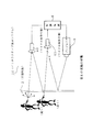
先ず、図1〜図10を参照して本発明の第1の実施の形態について説明する。 図1は、本発明の第1の実施の形態としての情報入力装置を備えてなるインタラクティブ表示システムの構成例を概念的に示している。
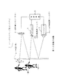
本実施の形態としてのインタラクティブ表示システム1は、半透明面2、赤外線発光ダイオード素子(LED:Light Emitted Diode )パネル3、CCD(Charge Coupled Device) カメラ4、プロジェクタ5、及び制御装置6を備えて構成される。赤外線LEDパネル3、CCDカメラ4、及びプロジェクタ5は半透明面2の背面側に対して設けられる。
<1. First Embodiment>
First, a first embodiment of the present invention will be described with reference to FIGS. FIG. 1 conceptually shows a configuration example of an interactive display system including an information input device as a first embodiment of the present invention.
An
半透明面2は、例えば透明なガラス板に対してトレーシングペーパーのような見え方をする半透明膜を貼り合わせる、あるいは磨りガラスのような半透明の性質を有するものを利用するなどして形成され、後述するようにして当該インタラクティブ表示システム1における操作パネルと表示パネルとの両者の機能を併せ持つ。
赤外線LEDパネル3は、例えばパネル面に対して多数の赤外線LEDが集合的に配列されることによって構成され、上記赤外線LEDから発光出力される赤外線光が半透明面の背面全体に対して照射されるように設けられる。上記赤外線LEDは制御装置6によって定常的に赤外線を発光するように駆動される。
なお、赤外線LEDパネル3としては、発光出力される赤外線光が半透明面2全体に対して照射されるのに充分な数の赤外線LEDが設けられればよい。また、後述するように、初期の赤外線画像に対する現在の赤外線画像の差分に基づいて半透明面2側から反射してくる画像情報を得るようにされることから、半透明面2全体に対して照射される赤外線光量が一律であるべき必要もない。従って赤外線LEDパネル3のサイズは、半透明面2よりもはるかに小さいもので済ませることができる。
The
The
The
CCDカメラ4は、撮像素子としてCCDを用いたカメラ装置であり、この場合には、半透明面2に映る画像光として赤外線光の成分のみを撮像することにより、半透明面2に対して行われた操作を画像情報として認識するために設けられる。このため、CCDカメラ4の光学系の部分に対しては、赤外線領域の波長帯域のみを透過する赤外線透過フィルタ4aが設けられる。また、CCDカメラ4により撮影される構図として半透明面2全体が含まれるようにその配置位置が設定される。
The
プロジェクタ5は、制御装置6から供給される画像情報に基づいて、可視光による画像光を半透明面2の背面に対して投影表示する。例えばユーザは、半透明面2に投影表示されたプロジェクタ5の画像を、半透明面2の前面側から観察することができる。ここで、プロジェクタ5の光学系には赤外線領域の波長を遮断する赤外線遮断フィルタ5aが設けられているが、これにより、半透明面2に投影表示される画像光には赤外線が含まれなくなるため、プロジェクタ5の投影画像は、CCDカメラ4からは不可視となる。
The
制御装置6は、例えばマイクロコンピュータを備えて構成され、CCDカメラ4から供給される撮像信号から画像情報(映像データ)を得て、更にこの画像情報をもとに操作情報を得る。そして、この操作情報に基づいて、例えばプロジェクタ5により半透明面2に表示させる画像に関する表示制御を実行する他、各種所要の制御処理を行う。また、赤外線LEDパネル3の赤外線LEDの発光駆動を行う。
なお、上記赤外線LEDパネル3、CCDカメラ4及びプロジェクタ5の配置位置は、それぞれが果たすべき役割が充分機能することを考慮して設定されればよい。
The
It should be noted that the arrangement positions of the
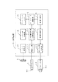
図2は、上記制御装置6の内部構成例を示すブロック図である。この図に示す制御装置6において、LED駆動部10は、赤外線LEDパネル3に設けられた複数の赤外線LEDを発光駆動するための回路部位である。
FIG. 2 is a block diagram showing an example of the internal configuration of the
画像入力部11は、CCDカメラ4から供給された撮像信号について所要の信号処理を施すことによって映像信号を生成して入力画像処理部12に供給する。つまり、画像入力部11では、半透明面2側からCCDカメラ4を介して入射してきた赤外線光を映像情報として出力する。
The
入力画像処理部12では、例えば画像入力部11から供給された映像信号をデジタル信号による映像信号データに変換する。入力画像処理部12においては、この映像信号データに基づいて得られる「画像情報(例えばフレーム単位の映像データ)」を利用して所要の解析処理等を実行することで、半透明面2に対して行われた操作情報を得るようにされる。ここで画像情報に基づいて得られる操作情報としては、例えば、半透明面2に対して操作を行っている操作体の画像上の位置(座標)や画像の信号レベルなどが用いられる。この操作情報はデータベース駆動部14に伝送される。また、上記映像信号データは、画像合成部17に対しても供給可能とされている。
For example, the input
しきい値制御部13は、入力画像処理部12にて実行される操作情報に関する処理に必要なしきい値を設定して入力画像処理部12に伝送する。上記入力画像処理部12では、しきい値制御部13において設定されるしきい値を利用して画像情報について解析を行うなど所要の処理を実行することで操作情報を得る。また、本実施の形態では後述するようにして入力画像データのフレーム差分を算出することにより、現在の半透明面2の画像状態(検出画像情報)を得るようにされるが、フレーム差分演算に利用する基準値(基準画像入力レベル)等の情報も、後述するようにして、しきい値制御部13に格納されるものとする。
The
データベース駆動部14は、入力画像処理部12により得られた操作情報を取り込み、この操作情報に基づいて適宜所要の処理を実行する。この際、データベース駆動部14が実行すべき制御処理に必要なプログラムデータはデータベースメモリ15に格納されており、データベース駆動部14は、データベースメモリ15に格納されたプログラムデータに基づいて所要の制御処理を実行することになる。
The
画像生成部16は、データベース駆動部14の制御によって、必要な画像データ(デジタル信号による映像信号データ)を生成して画像合成部17に出力する。
画像合成部17においては、必要があれば上記画像生成部16から供給された映像信号データに対して、入力画像処理部12から供給された映像信号データを合成してRGB信号生成部18に対して出力する。
RGB信号生成部18では、上記画像合成部17から供給された映像信号データについて、例えばアナログによるRGB信号に変換してプロジェクタ5に対して出力する。これにより、プロジェクタ5からは、半透明面2に対して行われる操作に応答した映像による画像光が半透明面2に対して照射出力されることになる。
The
In the
In the RGB
次に、上記構成による本実施の形態のインタラクティブ表示システム1における操作情報の検出方法について説明する。
前述のように、図1に示す半透明面2全体に対しては、その背面から赤外線LEDパネル3により赤外線光が照射されるのであるが、この赤外線光は半透明面2が半透明であることから、全ての赤外線光が半透明面2を通過するのではなく、幾分かの赤外線光が半透明面2の作用によって反射されることになる。
そして、本実施の形態においては半透明面2に対して何も操作が行われていないとされる状態のもとで、半透明面2にて反射される赤外線光をCCDカメラ4により撮像して得られる映像信号データの初期レベルを「基準入力画像レベル」として記憶する。この基準入力画像レベルは、入力された映像信号データに基づいて例えば1フレームにおける画素ごとの信号レベルを検出することにより行うようにすればよい。この検出処理は、入力画像処理部12により行われるものとされる。このようにして検出された基準入力画像レベルの情報はしきい値検出部13に伝送され、ここで保持されることになる。
Next, a method for detecting operation information in the
As described above, the entire
In the present embodiment, infrared light reflected by the
上記基準入力画像レベルの検出処理は、例えば図3のフローチャートに示すものとなる。この図に示すように、先ず入力画像処理部12では、ステップS101において、CCDカメラ4から画像入力部11を介して供給された映像信号から得られる1フレーム分の画像データに基づいて、上述のようにして画素ごとに信号レベルを検出し、この検出結果を基準入力画像レベルLintとして得る。なお、具体的には画素ごとの輝度信号成分のレベルを検出してこれを基準入力画像レベルLintとすることが考えられる。
入力画像処理部12は、続くステップS102において、上記基準入力画像レベルLintをしきい値制御部13に伝送して記憶させるように処理を実行する。
The reference input image level detection process is, for example, as shown in the flowchart of FIG. As shown in this figure, first, in the input
In the subsequent step S102, the input
なお、基準入力画像レベルLintを検出してしきい値制御部13に記憶させる処理(上記図3に示す処理動作)は、例えば当該インタラクティブ表示システムの電源オン時などに実行させたり、あるいは何らかのユーザの指示によって必要なときに基準入力画像レベルLintを更新させるように構成することが考えられる。
Note that the processing (the processing operation shown in FIG. 3) for detecting the reference input image level Lint and storing it in the
上記のようにして基準入力画像レベルLintの情報が保持された状態のもとで、操作情報として扱われる画像情報は次のようにして得るようにされる。
図4は、操作情報のもととなる画像情報(以下、この「画像情報」については特に「検出画像情報」という)を得るための入力画像処理部12の処理動作を示すフローチャートである。この場合、入力画像処理部12は、先ずステップS201において現在の入力画像レベルLprsを検出する処理を実行する。ここでいう入力画像レベルLprsは、現在においてCCDカメラ4により撮像された、赤外線光に基づく半透明面2の画像についてのフレーム単位のデータであり、このフレーム単位の画像データにおける画素ごとの信号レベルを検出して得られる情報である。
続いて、入力画像処理部12はステップS202において、基準入力画像レベルLintと上記現在の入力画像レベルLprsの差分を演算する(L=Lprs−Lint)ことによって差分入力画像レベルLを算出する。具体的には、基準入力画像レベルLintと上記入力画像レベルLprsとして得られたデータ値を、同一位置の画素ごとに差分を求めることによって差分入力画像レベルLを得るようにされる。従って、差分入力画像レベルLとしては、常に基準入力画像レベルLintに対する現在の入力画像レベルLprsとの信号レベル差が画素ごとに得られることになる。そして、入力画像処理部12は、ステップS203に進み、上記差分入力画像レベルLに基づいて、現在の検出画像情報(フレーム単位で画素ごとのレベル情報を有する形式の映像データ)を生成するようにされる。
Image information treated as operation information is obtained in the following manner while the information of the reference input image level Lint is held as described above.
FIG. 4 is a flowchart showing the processing operation of the input
Subsequently, in step S202, the input
上記のごとき検出画像情報の検出動作を、実際のユーザの半透明面2の前面側での動きと共に説明する。例えばユーザは、半透明面2の前面側において赤外線を反射可能な何らかの物体を利用して半透明面2の前面側において操作を行うようにするのであるが、ここでは、説明の簡単のためにユーザ自身の指や身体を用いることとする。
ここで、例えば図1に示すように半透明面2の前面側においてユーザが半透明面2から遠く離れた距離にいるときには、例えば半透明面2を通過してユーザの身体に反射するとされる赤外線光量は少ないことから、そのほとんどが半透明面2の前面から背面を通過して戻ることはない。このとき、上述した基準入力画像レベルLintと上記現在の入力画像レベルLprsとは同等であり、入力画像処理部12では、差分入力画像レベルLとしてほぼ0であると検出することになる。つまり、差分入力画像レベルLに基づいて生成される検出画像情報としては、初期状態と同様の変化の無いとされる状態が得られることになる。
The detection operation of the detected image information as described above will be described together with the movement of the actual user on the front side of the
Here, for example, as shown in FIG. 1, when the user is far away from the
ここで、例えば上記の状態からユーザが徐々に半透明面2に対して近づいていったとすると、半透明面2を通過してユーザの身体に反射する赤外線光のうち、半透明面2を通過して背面側に到達する光量が次第に増加していくことになる。この状態を、入力画像処理部12からみた場合には、ユーザの身体に対応する画像部分の基準入力画像レベルLintに対する現在の入力画像レベルLprsのレベルが徐々に増加していく状態として捉えられる。これに応じて、検出画像情報としては算出される差分入力画像レベルLに応じて、半透明面2に接近するユーザの姿が徐々に捉えられていくことになる。
そして、半透明面2に対して例えばユーザの体が非常に接近した状態(しきい値の設定にもよるが例えば半透明面2から30cm以内)では、その人体に反射した赤外線光がほとんど半透明面2を通過して背面側に到達することになるので、その身体形状がより鮮明な状態の検出画像情報が生成されることになる。
For example, if the user gradually approaches the
When the user's body is very close to the translucent surface 2 (for example, within 30 cm from the
また、ここでユーザがその身体を半透明面2からある程度距離を置いた状態で、例えば自身の指を手前にかざして半透明面2の非常に近い位置においたとする。
この場合、半透明面2に近接するユーザの指は他の身体部分よりも多くの赤外線光を反射するため、入力画像処理部12において得られる画像情報としては、ユーザの指にあたるに位置の画像領域のレベルが強く、その背景となる部分においてユーザの身体部分にあたる位置の画像領域のレベルは半透明面2からの距離に応じて弱くなることになる。そして、例えばこの状態のもとで、しきい値制御部13にて設定された所定のしきい値と検出画像情報とを比較すれば、容易にユーザの指にあたる部分のみの画像を背景から分離させることが可能であり、同様にしきい値の設定によっては、半透明面2から離れた距離にあるユーザの身体部分のみを抽出した画像情報を得ることも可能である。このようなしきい値は、前述のように実際に必要とされる条件に応じた値がしきい値制御部13において設定されるものである。
Here, it is assumed that the user places his / her body at a certain distance from the
In this case, since the user's finger close to the
このようにして、半透明面2の前面側の状態を検出する構成を採ることにより、この半透明面2を例えばインタラクティブなインターフェイスのための操作パネルとして機能させる場合には次のような利点が得られる。
先ず、本実施の形態では半透明面2側からの赤外線の反射光量によって得られる画像に基づいて操作情報を得ることになるので、操作を行うための操作体としては、特に特殊なポインティングデバイスを必要とせず、赤外線を反射する物体であればその種類は問わないことになる。つまり、操作体としては、上述のように人体全体もしくはその一部や、その他の何らかの物体を問題なく使用することができる。
In this way, by adopting a configuration for detecting the state of the front surface side of the
First, in the present embodiment, operation information is obtained based on an image obtained from the amount of reflected infrared light from the
また、例えばタッチパネルなどでは操作パネル面に対して指などの操作体を接触させる必要があるが、本実施の形態の場合には操作体の位置や動きは赤外線光の反射として検出されればよいことから、半透明面2に操作体を接触させる必要性はなく、その前面の空間において操作を行うような方法を採ることができる。
Further, for example, in a touch panel or the like, an operation body such as a finger needs to be brought into contact with the operation panel surface. In the case of the present embodiment, the position and movement of the operation body may be detected as reflection of infrared light. Therefore, it is not necessary to bring the operating body into contact with the
また、上述したように赤外線の反射光量は、操作体の半透明面2に対する距離に応じて変化するために、例えば操作体の半透明面2からの距離を操作情報として利用することも考えられる。
In addition, as described above, since the amount of reflected infrared light changes according to the distance of the operating body relative to the
更に、半透明面2は前述のように例えば透明のガラス板などに対してトレーシングペーパーのような半透明の薄膜を組み合わせたり、磨りガラスのようなものを利用するなどの簡略な手段により構成可能とされ、特にパネルに固有の駆動回路などは不要なので、低コストで容易に大型化を実現することができ、この点で大型化が困難なタッチパネルなどとは大きく異なる。
そして、半透明面2側からの赤外線の反射光により得られる画像に基づいて操作情報を得ることで、画像認識さえ可能であれば複数の操作体を同時に認識して所要の制御を実行させることが可能である。つまり、複数の異なる操作対象に対する同時操作が可能となるものであり、特に半透明面2が大画面として構成される場合には半透明面2上のいろいろな領域を利用して異なる種類の操作を同時に行うことができることにもなるので非常に有効となる。
Further, as described above, the
Then, by obtaining operation information based on an image obtained by infrared reflected light from the
そして、半透明面2は画像表示パネルとしての機能も有することから、例えば後述するように操作対象となるメニュー画面のようなものを表示させた上で、ユーザがこのメニュー画面に対して指などにより操作を行えるようにするなどの直接的な操作を実現することも容易に可能となる。
このように、本実施の形態としてのインタラクティブ表示システムでは、その操作情報を入力するのに多くの可能性が得られるために、これまでには無かったようなインタラクティブな入出力環境を容易に構築することができる。
Since the
As described above, the interactive display system according to the present embodiment provides many possibilities for inputting the operation information, and thus it is easy to construct an interactive input / output environment that has never existed before. can do.
次に、上記構成による本実施の形態のインタラクティブ表示システム1の利用例について、図5〜図9を参照して説明する。
図5には、本実施の形態のインタラクティブ表示システム1の第1の利用例として、メニュー操作を行う場合が示されており、ここでは半透明面2を前面側からみた状態が示されている。
例えばこの図に示すように、ユーザが半透明面2の前面に近づいたとすると、先ず、インタラクティブ表示システム1の制御装置6では、このときに得られる検出画像情報に基づいてユーザが近づいた半透明面2上の位置を認識する。そして、半透明面2上においてユーザが近づいたと認識された位置に対して、図のようにメニュー画面Mを表示するように表示制御を行う。このメニュー画面Mは当然のこととしてプロジェクタ5から半透明面2に対して投影された画像である。 そして、ユーザ自身が位置している付近の半透明面2上にメニュー画面Mが表示された状態のもとで、例えばユーザは自身の指を用いて、メニュー画面Mにおいて操作項目が表示されている任意の領域を指さすように指定したとする。このとき、ユーザの指先は、半透明面2上から3cm〜30cm程度の範囲内の距離にあるようにされる。
Next, usage examples of the
FIG. 5 shows a case where a menu operation is performed as a first usage example of the
For example, as shown in this figure, if the user approaches the front surface of the
これにより、例えばメニュー画面Mにおいては、ユーザが指し示した操作項目の領域が選択されたことを示す何らかの指示表示(例えば選択領域に対するカーソルの配置表示や所定の形態による強調表示など)が行われることになる。この強調表示のための表示制御は、検出画像情報に基づいてユーザの指が指し示している領域の座標を検出することにより実現される。
ここでは、上記のようにして指示表示が開始された状態から所定時間(例えば数秒程度)経過したときにエンター操作が行われたとみなすこととする。そして、ユーザがエンター操作を行った、つまり、特定の操作項目が強調表示された状態を所定時間以上維持させたとすると、指定された操作項目に従った所要の制御動作を実行することになる。例えば、指定された操作項目に従って、他の階層のメニュー画面を表示させたり、当該インタラクティブ表示システム1に対して所望の動作を実行させたりすることになる。あるいは、当該インタラクティブ表示システム1が何らかの外部機器を制御可能に構成されており、メニュー画面がその外部機器の動作についての操作制御を行うためのものであるとすれば、指定された操作項目に従って外部機器の動作を制御することになる。
なお、ユーザが半透明面2の前面から離れていき、ユーザと半透明面2との間にある程度以上の距離があいた場合には、それまで表示されていたメニュー画面Mは自動的に消去されるものとされる。
Thus, for example, on the menu screen M, some instruction display (for example, cursor placement display on the selected region or highlight display in a predetermined form) is performed indicating that the region of the operation item pointed to by the user has been selected. become. This display control for highlighting is realized by detecting the coordinates of the region pointed by the user's finger based on the detected image information.
Here, it is assumed that the enter operation is performed when a predetermined time (for example, about several seconds) has passed since the instruction display is started as described above. If the user performs an enter operation, that is, if a state in which a specific operation item is highlighted is maintained for a predetermined time or longer, a required control operation according to the specified operation item is executed. For example, according to the designated operation item, a menu screen of another hierarchy is displayed, or a desired operation is executed on the
When the user moves away from the front surface of the
ここで、図6のフローチャートに、上記図5に示した利用例に対応して実行される制御装置6の処理動作を示す。この図に示す処理動作は、主として制御装置6内の入力画像処理部12が検出画像情報に基づいて操作情報を認識すると共に、データベース駆動部14がデータベースメモリ15に格納されたプログラムに従って、上記操作情報に基づいて適宜処理動作を実行することにより実現されるものである。
Here, the flowchart of FIG. 6 shows the processing operation of the
この図に示すルーチンにおいては、先ずステップS301において現在の検出画像情報から「接近体」が検出されるか否かについて判別を行う。ここで、「接近体」とは半透明面2に対して所定の距離範囲まで接近した何らかの検出対象(図5ではユーザ自身の身体とされている)をいうものとされる。
この「接近体」の検出は、例えば入力画像処理部12が検出画像情報と接近体の検出用に設定されたしきい値(しきい値制御部13により設定される)を比較して、例えば検出画像情報のある領域においてこのしきい値以上の値が得られた場合には「接近体有り」と検出し、しきい値以上の値が得られる領域がない場合には、「接近体無し」と検出することになる。上記接近体検出用のしきい値は、例えば通常、人体(ユーザ)が半透明面2にある程度(例えば数十cm)近づいたときに検出画像情報として得られる人体部分の画像レベルに基づいて設定されればよい。
In the routine shown in this figure, first, in step S301, it is determined whether or not an “approaching object” is detected from the current detected image information. Here, the “approximate body” refers to some detection target (referred to as the user's own body in FIG. 5) that has approached the
This “approaching object” is detected by comparing, for example, the input
上記ステップS301において接近体が検出されなかった場合にはステップS308に進んで、ここで現在メニュー画面Mが表示中であるか否かについて判別が行われ、ここでメニュー画面Mが表示されていない場合には元のルーチンに戻る(即ち再度ステップS301の処理に移行する)が、メニュー画面Mが表示中の状態である場合にはステップS309に進み、メニュー画面Mを消去するための制御処理を実行する。このメニュー画面Mの消去処理は、例えばデータベース駆動部14が画像生成部16に対するメニュー画面Mの画像データの生成処理を停止することで実現される。
If no approaching object is detected in step S301, the process proceeds to step S308, where it is determined whether or not the menu screen M is currently displayed. Here, the menu screen M is not displayed. In this case, the process returns to the original routine (i.e., shifts to the process of step S301 again). However, if the menu screen M is being displayed, the process proceeds to step S309, and the control process for deleting the menu screen M is performed. Execute. The menu screen M erasing process is realized, for example, when the
これに対して、ステップS301において接近体が検出された場合には、ステップS302に進んで、半透明面2上における上記接近体の位置を検出することが行われる。この処理は、例えば検出画像情報における接近体の部分が占有する領域の座標を検出することで可能となる。この場合、検出すべき座標としては接近体の領域の所定の一地点であっても、所定規則に従って求められる複数地点であっても構わなく実際の使用環境等に応じて任意に設定されればよい。
On the other hand, when an approaching body is detected in step S301, the process proceeds to step S302, and the position of the approaching body on the
続くステップS303においては、上記ステップS302にて検出された接近体の位置に応じた半透明面2の領域に対してメニュー画面Mを表示させるための制御を実行する。この制御処理は、例えばデータベース駆動部14がデータベースメモリ15に格納されているメニュー画面表示用のプログラムに基づいて、画像生成部16において所要の種類のメニュー画面の画像データが作成されるよう
に制御を行うことになる。
この際、データベース駆動部14は、ステップS302にて検出された接近体の位置に対応する表示領域に対して、例えばメニュー画面の画像データをマッピングするようにして、表示用画像データを作成する。この結果、最終的にプロジェクタ5から投影される画像としては、半透明面2におけるユーザが近づいた位置に対してメニュー画面Mが表示されたものとなる。
In the subsequent step S303, control for displaying the menu screen M on the region of the
At this time, the
上記ステップS303の処理が実行された後は、ステップS304において、現在表示中のメニュー画面Mの操作項目とされる表示領域内において、「操作体」が検出されたか否かについて判別が行われる。ここで、「操作体」とは半透明面2の前面において至近距離(しきい値の設定にもよるが3cm〜30cm程度)にある物体(検出対象)のことをいうものとされる。つまり、図5においてはメニュー画面Mを指し示す指が対象となる。
そして、この「操作体」の検出処理は、先ず、操作体検出用としてしきい値制御部13において設定されたしきい値と、検出画像情報の画像レベルとを比較することにより、操作体の有無を検出することが行われる。このとき設定されるしきい値としては、半透明面2の前面において至近距離にある物体を背景から分離して検出する必要上、前述した接近体検出用のしきい値よりも大きい値が設定される。
そして、例えばしきい値と比較した結果、操作体が検出されたとすれば、その操作体が検出された検出画像情報上の座標位置を検出し、この検出位置とメニュー画面Mが表示されているとされる画像情報上の位置が一致しているか否かを判別することで、現在表示中のメニュー画面の表示領域内における操作体の有無を検出することになる。
After the process of step S303 is executed, in step S304, it is determined whether or not an “operation tool” has been detected in the display area that is the operation item of the currently displayed menu screen M. Here, the “operation body” refers to an object (detection target) at a close distance (approximately 3 cm to 30 cm depending on the setting of the threshold) on the front surface of the
Then, in the detection process of the “operation object”, first, the threshold value set in the threshold
For example, if an operating tool is detected as a result of comparison with a threshold value, the coordinate position on the detected image information from which the operating tool is detected is detected, and the detected position and the menu screen M are displayed. By determining whether or not the positions on the image information are the same, the presence or absence of the operating body in the display area of the currently displayed menu screen is detected.
上記ステップS304においてメニュー画面Mの操作項目とされる表示領域内において操作体が検出されない場合とは、検出画像情報上に操作体が検出されなかった(ユーザが至近距離で半透明面2上を指し示していないような状態)か、或いは、検出画像情報上に操作体を検出したとしても、この操作体の検出位置(座標)がメニュー画面Mの表示領域内に対応する画像情報上の領域に無かった(ユーザが至近距離で半透明面2上を指し示していた位置がメニュー画面Mの操作項目以外の領域であったような状態)ことになるが、このような場合にはステップS301に戻るようにされる。
The case where the operating tool is not detected in the display area which is the operation item of the menu screen M in the above step S304 means that the operating tool is not detected on the detected image information (the user moves on the
なお、ここで操作体が人体の手又は指に特定されるような場合には、ステップS304における操作体の検出処理として、例えば、データベースメモリ15に対して操作時に現れる人体の手又は指の形状の情報を記憶させておき、この手又は指の形状の情報と、検出画像情報として得られた画像形状とを比較して、その一致状態をみて操作体の検出の有無を識別するように構成することが可能である。本発明では、画像情報から入力情報を検出するために、検出画像情報に得られる画像の形状に基づいてもこれを操作情報として認識可能である。
When the operating body is specified as a human hand or finger, for example, as the operating body detection process in step S304, for example, the shape of the human hand or finger appearing during operation on the
ステップS304においてメニュー画面Mの操作項目とされる表示領域内において操作体が検出されたと判別された場合には、ステップS305に進んで、操作体が検出された位置に対応するメニュー画面Mの操作項目について指示表示が行われるように制御を実行してステップS306に進む。 If it is determined in step S304 that the operating tool has been detected within the display area that is the operation item of the menu screen M, the process proceeds to step S305, and the operation of the menu screen M corresponding to the position where the operating tool is detected. Control is performed so that instructions are displayed for the item, and the process proceeds to step S306.
ステップS306の処理はエンター操作の待機処理となる。前述のように、ここでのエンター操作は、指示表示が開始された状態から所定時間経過したときに確定されるものと規定している。そこで、ステップS306においては、ステップS304にて検出された操作体の検出状態が所定時間以上維持されるか否かについて検出を行うようにしている。この検出処理は、入力画像処理部12において現在の検出画像の状態遷移を監視することにより行われる。
そして、例えば現在の検出画像情報上から操作体が検出されなくなったり、あるいは現在の検出画像情報上における操作体の検出位置が、ステップS304にて検出されたメニュー画面Mの操作項目とされる表示領域内から外れたことが検出されたような場合には、ステップS306からステップS301以降の処理に戻ることになる。(この処理により、例えばユーザがこれまでとは異なるメニュー画面M上の操作項目を指し示すように、その指定位置を変更した場合には、新たに指定されたメニュー画面M上の操作項目に対して指示表示が行われたりすることになる。)
The process in step S306 is an enter operation standby process. As described above, the enter operation here is defined to be determined when a predetermined time elapses from the state in which the instruction display is started. Therefore, in step S306, detection is made as to whether or not the detection state of the operating tool detected in step S304 is maintained for a predetermined time or more. This detection process is performed by monitoring the state transition of the current detected image in the input
Then, for example, the operating tool is no longer detected from the current detected image information, or the detection position of the operating tool on the current detected image information is displayed as the operation item of the menu screen M detected in step S304. If it is detected that the region has fallen out, the process returns from step S306 to step S301. (By this process, for example, when the designated position is changed so that the user points to a different operation item on the menu screen M, the operation item on the newly designated menu screen M is changed. Instruction display will be performed.)
これに対して、ステップS306において、直前のステップS304にて検出された操作体の検出状態が所定時間以上維持されたと判別された場合には、エンター操作が行われたものとしてステップS307に進む。
ステップS307においては、メニュー画面M上において操作体が検出された位置の操作項目に応じた所要の制御処理が実行される。この処理は、データベース駆動部14がデータベースメモリ15に格納されたプログラムに従って実行することになる。
On the other hand, if it is determined in step S306 that the detection state of the operating tool detected in the immediately preceding step S304 has been maintained for a predetermined time or longer, the process proceeds to step S307 assuming that the enter operation has been performed.
In step S307, a required control process corresponding to the operation item at the position where the operating tool is detected on the menu screen M is executed. This process is executed by the
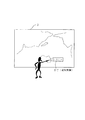
図7には、本実施の形態のインタラクティブ表示システム1の第2の利用例が示されている。この場合には、制御部6の制御によってプロジェクタ5から投影される画像として、世界地図が半透明面2上に表示されている。
例えば、この世界地図を表示するのに際しては、例えば図5に示したようなメニュー画面Mの操作により表示させるようにしてもよいし、ユーザ(説明者)が半透明面2に対してある程度近づいたときにこれを「接近体」として検出することにより自動的に表示させるようにすることも考えられる。また、このときの表示形態としても、半透明面2の前面で説明者が立っている水平方向の位置に対応して、基準となる国や地域(例えば日本)が常に説明者の位置する付近に表示されるようにすることなどが可能である。
そして、この場合には、地図(半透明面2)上で説明者が指し示した位置に対して、その指定された地域についての何らかの説明を行う説明画像DTが、地図上にインポーズされるようにして表示される。この場合には、制御装置6において、説明者が指等で指し示した位置(座標)を操作体として検出し、この検出した操作体の位置に一致するとされる地域の説明画像DTを表示するように制御することになる。なお、この場合の地図としての画像データや、各種説明画像DTは、データベースメモリ15に対して格納されているものとされる。
前述のように、本実施の形態のインタラクティブ表示システム1は表示画面(及び操作パネル)である半透明面2の大型化が容易であることから、この第2例のように、大型の半透明面2を利用した会議やデモンストレーションなどは、その用途として本実施の形態のインタラクティブ表示システム1として、十分に考えられるものである。
FIG. 7 shows a second usage example of the
For example, when the world map is displayed, it may be displayed by operating the menu screen M as shown in FIG. 5, for example, or the user (explainer) approaches the
In this case, an explanation image DT that explains something about the designated area is imposed on the map at the position indicated by the explainer on the map (semi-transparent surface 2). Is displayed. In this case, the
As described above, the
次に、図8に本実施の形態のインタラクティブ表示システム1の第3の利用例を示す。ここでは、2つのメニュー画面M1,M2が同時に表示されていると共に、これらメニュー画面M1,M2に対して、ユーザが同時に操作を行っている状態が示されている。
前述のように、本実施の形態ではCCDカメラ4にて撮像される赤外線光に基づいて得られる「検出画像情報」から操作情報を得るようにされる。つまり、画像状態を認識することにより操作情報を得る。このため、例えば図8の場合のように、操作体(ここではユーザの手や指)が検出画像情報上において、複数同時に検出されたとしても、各操作体についての検出結果をそれぞれ異なる操作情報として処理させることが可能である。
そこで、図8のように複数(ここでは2つ)のメニュー画面M1,M2を表示させた上で、ユーザがこれらメニュー画面M1,M2に対して両手を使用して同時に操作を行ったとしても、本実施の形態では、メニュー画面M1,M2に対して行われた操作に応答する所要の動作を実行するように構成することが可能である。特に、本実施の形態のインタラクティブ表示システム1は半透明面2の大型化が容易なので、このように操作対象となる画像を複数同時に表示してやるようにすれば、大型化された表示パネル(操作パネル)を有効に利用することができるものである。
Next, FIG. 8 shows a third usage example of the
As described above, in this embodiment, operation information is obtained from “detected image information” obtained based on infrared light imaged by the
Therefore, even if the user performs a simultaneous operation using both hands on the menu screens M1 and M2 after displaying a plurality of (here, two) menu screens M1 and M2 as shown in FIG. In the present embodiment, it is possible to perform a required operation in response to an operation performed on the menu screens M1 and M2. In particular, since the
図9は、本実施の形態のインタラクティブ表示システム1の第4の利用例を示している。この図においては、何らかの所定のパラメータ値を調整するためのパラメータ調整画像PC1,PC2が半透明面2に対して表示されていると共に、このパラメータ調整画像PC1,PC2に対してユーザが両手を使用して同時操作を行っている場合が示されている。このパラメータ調整画像PC1,PC2は、例えばスライドボリュームを模した形態により表示されている。
この場合、例えばユーザは自身の両手を、それぞれパラメータ調整画像PC1,PC2におけるレバー部分(レバー画像LV,LV)の表示された前面部に位置させ、所望のパラメータ値が得られるようにその手を上下方向にスライドさせるように動かすようにして操作を行うことになる。この場合には、この手の動きに応じてレバー画像LV,LVが上下に移動するように表示され、これに応じて実際のパラメータ値も可変制御されるように制御装置6における処理が適宜実行されることになる。この際、レバー画像LV,LVが同時に操作されたとしても、図8の場合と同様に、各操作情報を同時に認識してそれぞれの操作に応じたパラメータ値の変更を同時に行うように構成されるものである。
FIG. 9 shows a fourth usage example of the
In this case, for example, the user places his / her hands on the front portions of the parameter adjustment images PC1 and PC2 where the lever portions (lever images LV and LV) are displayed, and puts the hands so that a desired parameter value can be obtained. The operation is performed by moving it so as to slide up and down. In this case, the lever images LV and LV are displayed so as to move up and down according to the movement of the hand, and the process in the
図10に、本実施の形態のインタラクティブ表示システム1の第5の利用例を示す。この図では、大人と子供がそれぞれ同時に異なるメニュー画面を同時に操作している状態が示されている。
例えば、この場合の使用状況として、ユーザは立った状態で半透明面2に対する操作を行うことが通常であるとした場合、大人と子供では、図6にて説明したような検出画像情報上における接近体の占有率やその位置状態、及び、操作体として半透明面に現れる垂直方向における位置(高さ)が異なってくることになる。つまり、大人と子供との身長差によって、接近体としては大人よりも子供のほうが検出画像上においては下側の領域に現れることになり、同様に操作体(ユーザが指等により指し示す位置)も、大人よりも子供のほうが検出画像情報上においては下側の領域に現れる傾向となる。
FIG. 10 shows a fifth usage example of the
For example, as a usage situation in this case, when it is normal for the user to perform an operation on the
そこで、この第5の利用例では、例えばそのアプリケーションが大人と子供とで異なる種類の操作を行わせるようなものである場合には、検出画像情報上において高さ方向(垂直方向)に対して所定のしきい値を設定し、この所定のしきい値を越えるほどの高さを有する接近体或いは操作体が検出されたときには、半透明面2上においてこの接近体に対応する位置(この場合には表示位置として半透明面2上における高さも変更される)に大人用のメニュー画面Madを表示させ、しきい値を越えない高さの接近体或いは操作体が検出されたのであれば、半透明面2上の接近体に対応する位置(及び高さ)に対して子供用のメニュー画面Mchを表示させるように構成される。なお、上記しきい値としては、接近体と操作体とでそれぞれ異なる適切な値が設定されても構わないし、大人と子供を識別する高さ方向のしきい値としてもそれぞれ異なる値が設定されて構わない。また、第5の利用例においても、大人用のメニュー画面Madと子供用のメニュー画面Mchに対して同時に操作が行われた場合には、この操作情報を同時に認識してそれぞれに応答した制御動作が実行可能に構成される点では図8及び図9の場合と同様である。
Therefore, in this fifth usage example, for example, when the application is to perform different types of operations for adults and children, the height direction (vertical direction) on the detected image information When a predetermined threshold value is set and an approaching body or operation body having a height exceeding the predetermined threshold value is detected, a position corresponding to the approaching body on the translucent surface 2 (in this case) If the height of the display on the
また、図7〜図10に示した第2〜第5の利用例に関しては、フローチャートによる制御装置6の処理動作の説明は省略するが、何れの利用例においても、「接近体」或いは「操作体」の有無及びその位置(座標)を検出し、その検出結果と、半透明面2に表示されている何らかの操作対象画像との位置関係を識別することにより所要の制御動作を実行させる点では、図5の第1の利用例の場合と同様であり、図6に示したフローチャートに準じて各利用例における処理動作を実現することができるものである。
In addition, regarding the second to fifth usage examples shown in FIGS. 7 to 10, the description of the processing operation of the
<2.第2の実施の形態>
図11は、本発明の第2の実施の形態としてのインタラクティブ表示システムを示す図であり、図1と同一部分には同一符号を付して説明を省略する。また、制御装置6の内部構成は例えば図2に示したものと同様でよいものとされる。
この第2の実施の形態においては、図11に示すように、赤外線光を出射する赤外線発信器PDをポインティングデバイスとして使用するものとされる。
<2. Second Embodiment>
FIG. 11 is a diagram showing an interactive display system according to the second embodiment of the present invention. The same parts as those in FIG. The internal configuration of the
In the second embodiment, as shown in FIG. 11, an infrared transmitter PD that emits infrared light is used as a pointing device.
前述のように、本実施の形態ではCCDカメラ4により撮像される半透明面2からの赤外線光により得られる検出画像情報から操作情報を得るようにされる。つまり、本実施の形態においては半透明面2からCCDカメラ4に入射する赤外線光の光量に変化が与えられさえすれば、これを操作情報として認識することができることになる。
As described above, in this embodiment, the operation information is obtained from the detected image information obtained from the infrared light from the
例えば、先の第1の実施の形態においては、半透明面2の所望の位置をポインティングするのに指等を用いた代わりに、第2の実施の形態では、ユーザが上記赤外線発信器PDを手に持って、半透明面2の所望の位置に対して赤外線発信器PDにより出射された赤外線光を半透明面2の前面側に対して照射するようにされる。
このようにして赤外線発信器PDからの赤外線光が半透明面2に照射されると、このとき検出される検出画像情報としては、赤外線光の照射部分に対応する位置(座標)のレベルが周囲に対して変化することになる。そこで、制御装置6の入力画像処理部12では、この検出画像情報のレベル変化を操作情報として認識するように処理を行えばよいことになる。
なお、赤外線光は不可視であることから、例えば、半透明面2における赤外線発信器PDからの赤外線光の現在の照射位置が分かるように、スポットSPなどの表示を半透明面2上に行わせることが好ましい。このスポット表示は、制御装置6の入力画像処理部12が検出画像情報に基づいて現在赤外線光が照射されている位置(座標)を識別し、この識別された照射位置に対して、プロジェクタ5によるスポットSPの表示が行われるように表示制御を実行することで実現が可能である。
For example, in the previous first embodiment, instead of using a finger or the like to point to a desired position on the
When the infrared light from the infrared transmitter PD is irradiated onto the
Since the infrared light is invisible, for example, the spot SP is displayed on the
<3.第3の実施の形態>
図12及び図13は、それぞれ本発明の第3の実施の形態としてのインタラクティブ表示システム1B全体の構成と、制御装置6の内部構成を示すブロック図であり図1及び図2と同一部分については同一符号を付して説明を省略する。
<3. Third Embodiment>
FIGS. 12 and 13 are block diagrams showing the overall configuration of the interactive display system 1B as the third embodiment of the present invention and the internal configuration of the
図12及び図13に示すように、本実施の形態のインタラクティブ表示システム1Bとしては、第1CCDカメラ4A及び第2CCDカメラ4Bの2台のCCDカメラが設けられる。 第1CCDカメラ4Aは、先の実施の形態におけるCCDカメラ4と同一の役割が与えられているものとされる。つまり、半透明面2の背面側において半透明面2全体を撮像範囲として、ここから入射されてくる赤外線光を撮影するために設けられる。
As shown in FIGS. 12 and 13, the interactive display system 1B of the present embodiment is provided with two CCD cameras, a
第2CCDカメラ4Bは、後述するように半透明面2における所要の一部領域を拡大縮小して撮像するために設けられている。このため、第2CCDカメラ4Bには、図のようにパン/チルト/ズーム機構7が設けられる。パン/チルト/ズーム機構7は、第2CCDカメラ4Bを水平方向と垂直方向の両方向に回転移動させることのできる機構(パン/チルト機構)を備えると共に、第2CCDカメラに備えられているとされるズームレンズを移動させることにより撮像画像の拡大率を可変する機構(ズーム機構)を備えている。このパン/チルト/ズーム機構7に対する制御、つまりパン/チルト位置の可変制御及びズーム率の可変制御は、図13に示すようにデータベース駆動部14により行われる。従って、データベースメモリには、必要に応じてパン/チルト/ズーム機構7を制御するためのプログラムが格納されているものとされる。
なお、CCDカメラ4A,4Bの何れに対してもその光学系に赤外線透過フィルタ4aが備えられて、赤外線光のみによる半透明面2上の画像を撮像するようにされている。
The
Note that the optical system of each of the
この場合、制御装置6においては図13に示すように、第1CCDカメラ4A及び第2CCDカメラ4Bの2台のCCDカメラが設けられたことに対応して、2つの画像入力部11A,11Bが設けられることになる。画像入力部11Aは、第1CCDカメラ4Aの撮像信号を入力して映像信号として入力画像処理部12に対して供給し、画像入力部11Bは、第2CCDカメラ4Bの撮像信号を入力して映像信号として入力画像処理部12に対して供給する。従って、本実施の形態の入力画像処理部12では、第1CCDカメラ4Aの映像信号に基づいて得られる検出画像情報と、第2CCDカメラ4Bの映像信号に基づいて得られる検出画像情報を生成し、両者の検出画像情報から所要の操作情報を得るようにされる。
In this case, in the
本実施の形態としてのインタラクティブ表示システム1Bは例えば次のようにして使用することができる。
例えば図12に示すようにしてユーザが半透明板2の前面に位置した状態で、半透明板2のある位置に対して指で指定操作を行っているとする。この場合、半透明板2全体を撮像する第1CCDカメラ4Aにより撮像されて、入力画像処理部において得られる検出画像情報としては、例えば図14(a)に示すようなものとなる。上記のような操作を行っている場合、通常はユーザの指(手)の部分が最も半透明面2に近接し、残りの身体部分は手の部分よりも半透明面2から離れた距離にあることになる。
従って、図14(a)に示す検出画像情報においては、大きく分けて身体部分が表示される画像領域Aの部分よりも手の部分が表示される画像領域Bの部分のほうが高い値(例えば輝度レベル)が得られることになる。ここでしきい値制御部13においてしきい値を適切に設定することにより、入力画像処理部12において、画像領域Aの部分を含む背景から画像領域Bの部分を「操作体」として分離して識別できることは前述したとおりである。なお、前述のように操作体が人体の手又は指に限定される場合には、検出画像情報として得られるユーザの手間他は指の形状に基づいて、これを操作体として認識するように構成することも可能である。
The interactive display system 1B as the present embodiment can be used as follows, for example.
For example, it is assumed that the user performs a designation operation with a finger on a certain position of the
Therefore, in the detected image information shown in FIG. 14A, the image area B where the hand part is displayed has a higher value (for example, luminance) than the image area A where the body part is displayed. Level). Here, by appropriately setting the threshold value in the
ここで、上記のようにして入力画像処理部12が画像領域Bの部分を「操作体」として検出したとすると、データベース駆動部14は、上記半透明面2上における操作体の位置情報に基づいて、操作体の部分、つまり画像領域Bの部分を第2CCDカメラ4Bによりズーム撮影するように制御を実行する。つまり、半透明面2上における画像領域Bの部分の位置情報に基づいて、この画像領域Bの部分がほぼ第2CCDカメラ4Bの撮像画像のほぼ中心にくるように、パン/チルト/ズーム機構7に対してパン/チルト制御を実行したうえで、画像領域Bの部分が撮像画像のほぼ全体を占めるように、パン/チルト/ズーム機構7に対してズーム制御を実行する。このような制御によって、第2CCDカメラ4Bの撮像信号に基づいて得られる検出画像情報としては、図14(b)に示すように画像領域B(操作体)の部分が拡大された画像情報を得ることができる。
Here, if the input
例えば、上記図14(b)に示す検出画像情報に基づいて操作情報を得る場合として、特にその指定位置を操作情報として検出する場合、例えば図14(a)に示す検出画像情報に基づいてその指定位置情報を得る場合よりも、相対的な解像度が上がることになる。従って、より精度の高い指定位置情報を得ることが可能となる。 For example, when obtaining the operation information based on the detected image information shown in FIG. 14B, particularly when detecting the designated position as the operation information, for example, based on the detected image information shown in FIG. The relative resolution will be higher than when the designated position information is obtained. Therefore, it is possible to obtain designated position information with higher accuracy.
なお、上記した利用方法はあくまでも一例であって、2つのCCDカメラを利用した適用例は他にも各種考えられるものである。また、2つのCCDカメラに対してパン/チルト/ズーム機構7を設けてもよいし、更には2以上の複数のCCDカメラ(この際、どのCCDカメラにパン/チルト/ズーム機構を設けるのかは任意である)を利用して、これらCCDカメラの各々から独立的に操作情報を得るようにしても、多様な適用例が考えられるものである。 Note that the above-described usage method is merely an example, and various other application examples using two CCD cameras are conceivable. Further, the pan / tilt / zoom mechanism 7 may be provided for two CCD cameras, or more than two CCD cameras (which CCD camera is provided with the pan / tilt / zoom mechanism at this time). Even if the operation information is obtained independently from each of these CCD cameras by using (optional), various application examples can be considered.
<4.第4の実施の形態>
図15は本発明の第4の実施の形態としてのインタラクティブ表示システム1Cの構成例を概念的に示す図であり、例えば図1と同一部分については同一符号を付して説明を省略する。また、制御装置6の内部構成は図2と同様でよいものとされる。
これまで実施の形態として説明してきた各インタラクティブ表示システムは、半透明面2がいわゆる壁面状であるものとして説明してきたのであるが、本発明としての半透明面2の機能(表示パネル機能及び操作パネル機能)を考慮すれば、これに限定されるものではない。そこで、第4の実施の形態のインタラクティブ表示システム1Cでは、半透明面2Aを曲面形状に形成している。図15においては、半球面状とされた半透明面2Aが設置されている状態が示されており、この半球面状の半透明面2Aの内壁側に対して、例えば少なくとも赤外線LEDパネル3、CCDカメラ4、及びプロジェクタ5が設けられるようにされる。ユーザは半透明面2Aの外壁側から操作を行うことになる。なお、この図においては、CCDカメラ4に対して設けられる赤外線透過フィルタ4aと、プロジェクタ5に対して設けられる赤外線遮断フィルタ5aの図示は省略しているが、実際には、これまでの実施の形態と同様に設けられているものとされる。
なお、この図では半透明面2Aに対して世界地図が投影表示されている状態が示されているが、例えばこの場合であれば、先の第1の実施の形態において図7にて説明したようにして利用することが考えられる。
<4. Fourth Embodiment>
FIG. 15 is a diagram conceptually showing a configuration example of an interactive display system 1C as a fourth embodiment of the present invention. For example, the same parts as those in FIG. The internal configuration of the
Each interactive display system described so far in the embodiment has been described assuming that the
In this figure, a state in which a world map is projected and displayed on the semi-transparent surface 2A is shown. For example, in this case, as described in FIG. 7 in the first embodiment. It can be considered to be used in this way.
<5.第5の実施の形態>
図16は、本発明の第5の実施の形態としてのインタラクティブ表示システム1Dの構築例を概念的に示す図であり、図1と同一部分については同一符号を付して説明を省略する。この図においても、赤外線透過フィルタ4aと赤外線遮断フィルタ5aの図示は省略しているが、実際には、CCDカメラ4とプロジェクタ5に対してそれぞれ設けられているものである。また、ここでは制御装置6の図示も省略されているが、実際には、赤外線LEDパネル3、CCDカメラ4、及びプロジェクタ5に対する制御を実現するために設けられているものであり、その内部構成も図2と同様でよい。
<5. Fifth embodiment>
FIG. 16 is a diagram conceptually showing a construction example of an interactive display system 1D as the fifth embodiment of the present invention. The same parts as those in FIG. Also in this figure, the
この場合には、例えば通路の壁面が半透明面2として構成されており、例えば赤外線LEDパネル3、CCDカメラ4、及びプロジェクタ5などは、この通路壁面(半透明面2)の背後に設けられる。つまり、本実施の形態のインタラクティブ表示システム1Dは通路の壁面の一部として構成されている。
ここで、たとえばユーザ(歩行者)が通路を歩いており、インタラクティブ表示システム1Dの半透明面2(壁面)の脇を通過したとする。
前述のように、本発明では操作パネルとして機能する半透明面2からある程度離れた距離にユーザがいたとしても、これを「接近体」として検出することが可能である。そこで、この場合には、歩行者がインタラクティブ表示システム1Dの半透明面2(壁面)の脇にきたときに、その姿が接近体として検出するようにされる。そして接近体の検出結果に基づいて、例えば図16に示すように壁面である半透明面2に対して、行き先などを提示する案内画像GDをプロジェクタ5により投影表示するように動作させることができる。
このようなインタラクティブ表示システム1Dの動作を歩行者からみたときには、自分が通路を歩くと壁面に対して自動的に行き先の案内表示が行われることになる。
In this case, for example, the wall surface of the passage is configured as a
Here, for example, it is assumed that the user (pedestrian) is walking along the passage and passes by the side of the translucent surface 2 (wall surface) of the interactive display system 1D.
As described above, in the present invention, even if the user is at a distance from the
When such an interactive display system 1D is viewed from a pedestrian, the destination guidance display is automatically performed on the wall surface when the person walks along the passage.
また、上述した第5の実施の形態において、例えば通路の壁面の裏側において、赤外線LEDパネル3、CCDカメラ4、プロジェクタ5(及び制御装置6)などの設置スペースが限られているような状況では、図17のようにミラーMRを用いて赤外線LEDパネル3、プロジェクタ5の出射光やCCDカメラ4の入射光を光路を反射により変更させるようにすることが考えられる。特に、CCDカメラ4やプロジェクタ5の画角によっては、大画面化された半透明面2をカバーできるだけの撮像範囲や投影表示範囲を得るのには相当の距離が必要となるのであるが、このようにしてミラーMRを設ければ、狭い奥行きであっても充分な撮像範囲や投影表示範囲を得ることが可能となり、本実施の形態のインタラクティブ表示システム1Dを設置環境として要求される条件を緩和させることができる。
In the fifth embodiment described above, for example, in the situation where the installation space for the
<6.第6の実施の形態>
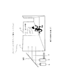
図18は、本発明の第6の実施の形態としてのインタラクティブ表示システム1Eの構成例を概念的に示す図であり、図1と同一部分については同一符号を付して説明を省略する。また、この図においても赤外線透過フィルタ4aと赤外線遮断フィルタ5aの図示は省略されているが、実際にはCCDカメラ4とプロジェクタ5に対して備えられるものである。
<6. Sixth Embodiment>
FIG. 18 is a diagram conceptually showing a configuration example of an interactive display system 1E as a sixth embodiment of the present invention. The same parts as those in FIG. In this figure, the
この場合には、半透明面2Bはテーブルとして設置されている。つまり、4本のテーブル脚F,F,F,Fにより指示されることにより、通常の家具としてのテーブルの天面としても機能している。この場合、半透明面2Bの下面側に対して図のように赤外線LEDパネル3、CCDカメラ4、プロジェクタ5(及び制御装置6)が設けられる。
また、本実施の形態においては、後述するようにしてユーザが半透明面2Bに対して操作を行うことによって、モニタ装置30に対する操作制御が行えるようにされている。
In this case, the
In the present embodiment, the user can perform operation control on the
図19には、本実施の形態のインタラクティブ表示システム1Eとしての制御装置6の内部構成を示すブロック図であり、図2Bと同一部分については同一符号を付して説明を省略する。
この図に示す制御装置6においては、外部機器制御部20が設けられる。この場合、外部機器制御部20は、モニタ装置30に対する操作制御を行うための回路部位とされ、データベース駆動部14から与えられる操作情報によって、テレビジョン受像機30に対して所要の操作制御を行うためのコマンド信号を送信出力する。従って、この場合のデータベースメモリ14には、当該インタラクティブ表示システム1Eによりテレビジョン受像機30に対する操作が実現されるようにするためのプログラムが格納されることになる。
FIG. 19 is a block diagram showing the internal configuration of the
In the
この第6の実施の形態としてのインタラクティブ表示システム1Eにおいては、例えば図18に示すように、半透明面2Bの特定の領域にリモートコントロール(以下リモコンと略す)表示RMDが表示される。このリモコン表示RMDには、テレビジョン受像機30に対する各種操作が可能なキーが設けられたリモートコントローラの操作パネル面を模した形態により表示が行われるものとされる。なお、このリモコン表示RMDの表示制御は、データベースメモリ14に格納されているとされるリモコン表示RMDの画像データ利用してデータベース駆動部14が表示制御を行うことで、リモコン表示RMDの映像がプロジェクタ5により投影表示されるようにすることで実現される。
なお、リモコン表示RMDの表示位置は任意に設定されればよく、例えば当該インタラクティブ表示システム1Eに対する所定の設定操作によって、ユーザが使いやすいとされる位置に表示されるように任意に設定できるようにすることも考えられる。この際、データベース駆動部14が現在のリモコン表示RMDの表示位置を認識してさえいれば、リモコン表示RMDの各種キーの表示部分の位置(座標)は、常にデータベース駆動部14において把握することが可能である。
In the interactive display system 1E as the sixth embodiment, for example, as shown in FIG. 18, a remote control (hereinafter abbreviated as “remote control”) display RMD is displayed in a specific area of the
The display position of the remote control display RMD may be arbitrarily set. For example, by a predetermined setting operation on the interactive display system 1E, the display position can be arbitrarily set to be displayed at a position that is easy for the user to use. It is also possible to do. At this time, as long as the
例えば、上記半透明面2Bに表示されたリモコン表示RMDに対するユーザの操作として、ここでは、数字キーの操作によって所望のチャンネルを選択したとする。このとき、例えばユーザは半透明面2B上のリモコン表示RMDにおける数字キーのうち、所望の1つの数字キーを押圧操作するようなイメージで半透明面2B上に対して操作を行えばよい。この場合、しきい値制御部13におけるキー操作判別のためのしきい値の設定にもよるが、ユーザは必ずしもテーブル面(半透明面2B)上に対して指などの操作体を接触させる必要はなく、所望のキーが表示されている部分の中空に対して操作を行うようにするだけでもキー操作として判別可能なようにすることは当然可能である。
For example, as a user operation on the remote control display RMD displayed on the
上記したユーザの操作は、CCDカメラ4により撮像されて得られる検出画像情報に基づいて、入力画像処理部12においてその操作位置(座標)が検出される。そして、データベース駆動部14では、検出された操作位置の座標が、リモコン表示RMDとして表示されているどのキー部分の座標と一致するのかを識別して、例えば操作位置の座標と一致しているキーの種別を示す情報を外部機器制御部20に対して伝送する。
外部機器制御部20においては、データベース駆動部14から入力されたキー種別を示す情報に基づいて、このキー種別に対応するコマンド信号をモニタ装置30に出力する。
この場合には、ある1つの数字キーによるチャンネル切換操作であることから、例えばデータベース駆動部14は、チャンネル番号に対応する数字による数字キーが操作されたとの情報を伝送することになる。そして、外部機器制御部20では、この指定された数字キーが示すチャンネル番号に切り換えるためのコマンド信号を送信する。これにより、テレビジョン受像機30においては、ユーザが操作したチャンネルの画面に切り替わるように動作することになる。
The operation position (coordinates) of the above-described user operation is detected by the input
The external
In this case, since it is a channel switching operation using a certain number key, for example, the
なお、当然のこととして当該インタラクティブ表示システム1Eにより操作が可能な外部機器はテレビジョン受像機に限定される物ではなく、他の各種電子機器に対しても操作が可能なように構成することは可能であり、更には本発明に基づけば、同時に複数種類の機器に対応するリモコン表示RMDを表示させてユーザによる操作が可能なように構成することも可能であり、また、1つのリモコン表示RMDにおける複数キーに対する同時操作を認識して外部機器を制御することも可能とされる。 As a matter of course, the external device that can be operated by the interactive display system 1E is not limited to the television receiver, and may be configured to be able to operate other various electronic devices. Further, according to the present invention, it is possible to display a remote control display RMD corresponding to a plurality of types of devices at the same time so that the user can perform an operation, and one remote control display RMD is also possible. It is also possible to control external devices by recognizing simultaneous operations on a plurality of keys.
また、本実施の形態のように半透明面2Bがテーブル面である場合には、次のような動作も行わせることができる。
例えば、テーブル面としての半透明面2Bに対して食器その他の何らかの物を置いた場合、この半透明面2Bに置かれた物が赤外線光を反射することにより、この設置物の形状の画像が検出画像情報として得られることになる。これまで説明してきた実施の形態では、このような画像変化を操作情報として扱ってきたが、この場合には、この検出画像情報としての画像データをプロジェクタ5により投影表示させる画像として利用することもできる。これにより、例えば図18の影表示SHDとして示すように、半透明面2Bに対して置かれた物の画像を、その影のようにして表示できるように構成することが考えられる。この場合、物が置かれる位置に応じて半透明面2B上の影表示SHDの位置も追随するようにして変化したり、半透明面2Bの表面からの距離変化に応じて影表示SHDの形状なども変化するので、ユーザにとって興味深い視覚的効果が得られることになる。
Further, when the
For example, when a tableware or some other object is placed on the
上記のような影表示SHDを実現するためには、例えば制御装置6の入力画像処理部12において得られる検出画像情報を画像データとして画像合成部17に供給すればよい。これにより、画像合成部17においては、上記検出画像情報としての画像データ(影表示SHDの画像データ)と、データベース駆動部14の制御により画像生成部16において作成されたリモコン表示RMDが合成されることで、最終的に図18に示すような半透明面2Bに対する投影表示が行われることになる。
なお、ここでは詳しい説明は省略するが、上記検出画像情報を画像データに対して各種信号処理によって、マルチカラー化を施したり、画像の形状を変化させるなどの特殊効果を与えることで更に視覚的効果を高めるように構成することも可能である。
In order to realize the shadow display SHD as described above, for example, detected image information obtained in the input
Although detailed explanation is omitted here, the detected image information can be further visualized by applying special effects such as multi-coloring or changing the shape of the image by various signal processing on the image data. It can also be configured to enhance the effect.
ところで、上述の第6の実施の形態では、テーブルの下側に少なくとも赤外線LEDパネル3、CCDカメラ4、プロジェクタ5を配置してやる必要があるが、例えば床からテーブル面(半透明面2B)までの高さ(距離)はさほど多く取ることができないため、CCDカメラ4やプロジェクタ5が半透明面2B全体をカバーできるのに必要な直線距離を得ることが難しい場合が生じる。そこで、先の第5の実施の形態でも説明したが、この場合も同様に、図20に示すように半透明面2B(テーブル面)の下側に光路を反射により変更させるミラーMRを配置させ、赤外線LEDパネル3、CCDカメラ4、及びプロジェクタ5などの装置はテーブルの横側に配置させるようにすることが考えられる。
By the way, in the above-described sixth embodiment, at least the
なお、ミラーMRの代わりに、所定の光透過率と反射率が設定されたハーフミラーMRを用いることも考えられる。このようなハーフミラーMRを用いた場合には、例えば、赤外線LEDパネル3はテーブルの横側に配置させずに、テーブル下部の床面部分に設置することなどが可能となってそれだけ設置自由度が高くなる。なお、ハーフミラーを用いた設置方法は、たとえば先の第5の実施の形態における図17のような設置形態の場合にも適用することができる。
Instead of the mirror MR, a half mirror MR in which predetermined light transmittance and reflectance are set may be used. When such a half mirror MR is used, for example, the
<7.第7の実施の形態>
図21は本発明の第7の実施の形態としてのインタラクティブ表示システム1Fの構成例を示す図であり、図1と同一部分には同一符号を付して説明を省略する。
インタラクティブ表示システム1Fにおいては、赤外線LEDパネル3が設けられていない。
たとえば、本発明に基づくインタラクティブ表示システムを屋外などの外光の強い環境で使用する場合、たとえば日中の自然光に含まれる赤外線が強いために、図1に示すような赤外線LEDパネル3から照射される赤外線光を操作情報検出用の光源とする構成では、赤外線LEDパネル3から照射される赤外線光の強度が自然光に含まれる赤外線に対して相対的に弱まるので、場合によっては適切な操作情報の検出が行われない(つまり操作情報を認識可能な適正な検出画像情報が得られない)可能性がある。
そこで、このような場合には、本実施の形態のように赤外線LEDパネル3を省略する代わりに、自然光に含まれる赤外線光を操作情報検出用の光源として利用するものである。
この場合、検出画像情報を得るために必要な基準入力画像レベルLintは、例えば接近体及び操作体等の検出対象が無い(半透明面2に対して何の操作も行われていない)とされる状態のもとで、その前面側から半透明面2を透過してCCDカメラ4において撮像される撮像信号から得た画像情報に基づいて検出するようにされる。
<7. Seventh Embodiment>
FIG. 21 is a diagram showing a configuration example of an interactive display system 1F as a seventh embodiment of the present invention. The same parts as those in FIG.
In the interactive display system 1F, the
For example, when the interactive display system according to the present invention is used in an environment with strong outside light such as outdoors, the
In such a case, instead of omitting the
In this case, the reference input image level Lint necessary for obtaining the detected image information is assumed that there is no detection target such as an approaching body and an operating body (no operation is performed on the translucent surface 2). In this state, detection is performed based on image information obtained from an imaging signal that is transmitted through the
そして、例えば半透明面2に対して何らかの操作が行われるとすると、このと
きの半透明面2における接近体及び操作体などの部分をCCDカメラ4側からみた場合には、接近体及び操作体などにより自然光の赤外線が遮られることから、これを自然光に含まれる赤外線光の影として見ることができる。本実施の形態のい制御装置6では、基準入力画像レベルLintに対して、画像レベルがより低くなる(暗くなる)ようにして変化する画像情報を操作情報として扱うことになる。
なお、インタラクティブ表示システム1Fの制御装置6の内部構成の図示は省略するが、赤外線LEDパネル3が省略されたことに応じて、LED駆動部10が設けられないことになる。
For example, if any operation is performed on the
In addition, although illustration of the internal structure of the
<8.第8の実施の形態>
図22は、本発明の第8の実施の形態としてのインタラクティブ表示システム1Gの構成を示す概念図、図23は本実施の形態のインタラクティブ表示システム1Gに備えられる制御装置6の構成を示すブロック図であり、それぞれ図1及び図2と同一部分については同一符号を付して説明を省略する。
インタラクティブ表示システム1Gとしては、先に説明した各種実施の形態のインタラクティブ表示システムに備えられた赤外線LEDパネル3の代わりにマイクロ波発生器40が備えられ、また、CCDカメラ4の代わりにマイクロ波受信器41が備えられる。
<8. Eighth Embodiment>
FIG. 22 is a conceptual diagram showing a configuration of an interactive display system 1G as an eighth embodiment of the present invention, and FIG. 23 is a block diagram showing a configuration of a
As the interactive display system 1G, a
そして、これに対応して制御装置6においては、マイクロ波発生器40を駆動するためのマイクロ波駆動回路110がLED駆動部10(図1参照)の代わりに備えられる。また、マイクロ波受信器41から供給される受信マイクロ波を入力して例えば所定形式のデータに変換して出力する画像信号入力部111と、この画像信号入力部111から供給されるマイクロ波の受信データを入力して所要の処理を行うことにより、例えば検出画像情報を得ると共にこの検出画像情報に基づいて操作情報を得る入力データ処理部112が設けられる。上記画像信号入力部111及び入力データ処理部112は、それぞれ画像入力部11及び入力画像処理部12(図1参照)に代わる機能回路部である。この場合、操作情報検出用の媒体としてマイクロ波を利用するため、CCDカメラ4に備えられた赤外線透過フィルタ4aや、プロジェクタ5に備えられた赤外線遮断フィルタ5aは不要となる。
本実施の形態のように、それが照射された物体に反射する性質を有するマイクロ波のような媒体を操作情報の検出に利用するように構成しても、これまで説明してきた実施の形態(赤外線を操作情報の検出に利用した例)と同様にして本発明としての情報処理装置を構成することが可能である。
Correspondingly, in the
Even if it is configured such that a medium such as a microwave having a property of reflecting an object irradiated with the object is used for detection of operation information as in the present embodiment, the embodiment described so far ( The information processing apparatus according to the present invention can be configured in the same manner as in the case of using infrared rays for detecting operation information.
なお、特に具体的な適用例の図示及び説明は省略するが、本発明としては半透明面2に対して行われたとされる操作情報が検出されればよいことから、上記各実施の形態に示したプロジェクタ5を省略して本発明としての情報処理装置を構成することは当然考えられる。つまり、この場合の半透明面2は操作パネルとしてのみ機能する。この構成に準ずる場合、たとえばインタラクティブな応答表示をする表示手段が必要であれば、半透明面2ではなく、別の他の種類の表示デバイスを使用しても構わない。
また、本発明に基づいて構成されるインタラクティブ表示システムの適用例は、これまで述べてきた実施の形態や適用例に限定されるものではなく、本発明としての入力装置の利点を活かした操作方法やアプリケーションなどの適用は、他にも各種考えられるものである。また、本発明の実施の形態としてのインタラクティブ表示システムにおいて、インタラクティブな応答を音声により行うことも考えられる。
In addition, although illustration and description of a specific application example are omitted, it is only necessary to detect operation information performed on the
Further, the application example of the interactive display system configured based on the present invention is not limited to the embodiment and application examples described so far, and an operation method utilizing the advantages of the input device as the present invention. There are various other possible applications of the application and application. Moreover, in the interactive display system as an embodiment of the present invention, interactive response may be performed by voice.
1,1A,1B,1C,1D,1E,1F,1G インタラクティブ表示システム、2,2A,2B 半透明面、3 赤外線LEDパネル、4 CCDカメラ、4A 第1CCDカメラ、4B 第2CCDカメラ、5 プロジェクタ、6 制御装置、7 パン/チルト/ズーム機構、10 LED駆動部、11,11A,11B 画像入力部、12 入力画像処理部、13 しきい値制御部、14 データベース駆動部、15 データベースメモリ、16 画像生成部、17 画像合成部、18 RGB信号生成部、30 テレビジョン受像機、40 マイクロ波発生器、41 マイクロ波受信器、110 マイクロ波駆動部、111 受信信号入力部、112 入力データ処理部、PD 赤外線発信器、MR ミラー、ハーフミラー、RMD リモコン表示、SHD 影表示 1, 1A, 1B, 1C, 1D, 1E, 1F, 1G interactive display system, 2, 2A, 2B translucent surface, 3 infrared LED panel, 4 CCD camera, 4A first CCD camera, 4B second CCD camera, 5 projector, 6 control device, 7 pan / tilt / zoom mechanism, 10 LED drive unit, 11, 11A, 11B image input unit, 12 input image processing unit, 13 threshold control unit, 14 database drive unit, 15 database memory, 16 image Generation unit, 17 image composition unit, 18 RGB signal generation unit, 30 television receiver, 40 microwave generator, 41 microwave receiver, 110 microwave drive unit, 111 received signal input unit, 112 input data processing unit, PD infrared transmitter, MR mirror, half mirror, RMD remote control display, HD shadow display
Claims (6)
前記半透明面に情報を表示する情報表示部と、
画像を撮像する撮像部と、
前記撮像部により撮像された画像に基づいて前記表示部に対する信号、および情報処理装置の所定のパラメータ値を変更するためのパラメータ変更信号を出力する制御部と、
前記半透明面に所定の波長帯域の光を照射する照射部とを含み、
前記撮像部は、撮像素子と、前記所定の波長帯域の光のみを透過するフィルタとを備え、
前記制御部は、前記撮像部により撮像された画像に基づき、前記半透明面の近傍における操作体の動きの方向を認識し、当該動きの方向に応じた前記表示部に対する信号を出力すると共に、当該動きの方向に応じたパラメータ変更信号を出力すること
を特徴とする情報処理装置。 A translucent surface,
An information display unit for displaying information on the translucent surface;
An imaging unit that captures an image;
A control unit that outputs a signal for the display unit based on an image captured by the imaging unit and a parameter change signal for changing a predetermined parameter value of the information processing device;
An irradiation unit that irradiates light of a predetermined wavelength band to the translucent surface,
The imaging unit includes an imaging device and a filter that transmits only light in the predetermined wavelength band,
The control unit recognizes the direction of movement of the operating body in the vicinity of the translucent surface based on the image captured by the imaging unit, and outputs a signal to the display unit according to the direction of the movement, An information processing apparatus that outputs a parameter change signal according to the direction of the movement.
前記制御部は、前記撮像部により撮像された画像に基づき、前記半透明面に対して前記操作体が近接することによって生じる所定の波長帯域の光の強度が変化する領域の大きさを認識し、当該領域の大きさに応じた前記表示部に対する信号を出力することを特徴とする情報処理装置。 The information processing apparatus according to claim 1,
The control unit recognizes the size of a region in which the intensity of light in a predetermined wavelength band, which is generated when the operating body approaches the semitransparent surface, based on an image captured by the imaging unit. An information processing apparatus that outputs a signal to the display unit in accordance with the size of the area.
前記制御部は、前記撮像部により撮像された画像に基づき、前記半透明面と前記操作体との距離が変化することによって生じる所定の波長帯域の光の強度の変化を認識し、当該強度の変化に応じた前記表示部に対する信号を出力することを特徴とする情報処理装置。 The information processing apparatus according to claim 1,
The control unit recognizes a change in intensity of light in a predetermined wavelength band caused by a change in the distance between the translucent surface and the operation body based on an image captured by the imaging unit, An information processing apparatus that outputs a signal to the display unit according to a change.
前記情報処理装置はテーブル状の形状を有し、
前記半透明面はテーブル面に配置され、
前記撮像部はテーブルの下部からテーブル面を撮像するように配置され、
前記照射部はテーブルの下部からテーブル面に向けて光を照射するように配置されていること
を特徴とする情報処理装置。 The information processing apparatus according to claim 1,
The information processing apparatus has a table shape,
The translucent surface is disposed on a table surface;
The imaging unit is arranged to image the table surface from the bottom of the table,
The information processing apparatus, wherein the irradiation unit is arranged to irradiate light from a lower part of the table toward the table surface.
前記撮像部および前記照射部は、テーブル下部に設けられたミラーによる反射を利用することで、テーブル面を撮像および照射を行うことを特徴とする情報処理装置。 The information processing apparatus according to claim 4.
The information processing apparatus, wherein the imaging unit and the irradiation unit perform imaging and irradiation on a table surface by using reflection by a mirror provided at a lower part of the table.
前記所定の波長帯域の光のみを透過するフィルタを介して前記撮像部の撮像素子により画像を撮像し、
前記撮像部により撮像された画像に基づき、前記半透明面の近傍における操作体の動きの方向を認識し、
当該動きの方向に応じた前記表示部に対する信号を出力すると共に、当該動きの方向に応じたパラメータ変更信号を出力すること
を特徴とする情報処理方法。 A translucent surface, an information display unit that displays information on the translucent surface, an imaging unit that captures an image, a signal for the display unit based on an image captured by the imaging unit, and a predetermined information processing device In an information processing method of an information processing apparatus, including a control unit that outputs a parameter change signal for changing the parameter value of the light source, and an irradiation unit that irradiates the semitransparent surface with light of a predetermined wavelength band,
An image is captured by the image sensor of the imaging unit through a filter that transmits only light in the predetermined wavelength band,
Recognizing the direction of movement of the operating body in the vicinity of the translucent surface based on the image captured by the imaging unit,
An information processing method characterized by outputting a signal for the display unit corresponding to the direction of the motion and outputting a parameter change signal corresponding to the direction of the motion.
Priority Applications (1)
| Application Number | Priority Date | Filing Date | Title |
|---|---|---|---|
| JP2007102037A JP4712754B2 (en) | 2007-04-09 | 2007-04-09 | Information processing apparatus and information processing method |
Applications Claiming Priority (1)
| Application Number | Priority Date | Filing Date | Title |
|---|---|---|---|
| JP2007102037A JP4712754B2 (en) | 2007-04-09 | 2007-04-09 | Information processing apparatus and information processing method |
Related Parent Applications (1)
| Application Number | Title | Priority Date | Filing Date |
|---|---|---|---|
| JP18093697A Division JP3968477B2 (en) | 1997-07-07 | 1997-07-07 | Information input device and information input method |
Related Child Applications (1)
| Application Number | Title | Priority Date | Filing Date |
|---|---|---|---|
| JP2009256385A Division JP4687820B2 (en) | 2009-11-09 | 2009-11-09 | Information input device and information input method |
Publications (2)
| Publication Number | Publication Date |
|---|---|
| JP2007200353A true JP2007200353A (en) | 2007-08-09 |
| JP4712754B2 JP4712754B2 (en) | 2011-06-29 |
Family
ID=38454824
Family Applications (1)
| Application Number | Title | Priority Date | Filing Date |
|---|---|---|---|
| JP2007102037A Expired - Fee Related JP4712754B2 (en) | 2007-04-09 | 2007-04-09 | Information processing apparatus and information processing method |
Country Status (1)
| Country | Link |
|---|---|
| JP (1) | JP4712754B2 (en) |
Cited By (4)
| Publication number | Priority date | Publication date | Assignee | Title |
|---|---|---|---|---|
| JP2009069970A (en) * | 2007-09-11 | 2009-04-02 | Fujitsu Ltd | Information providing device, information providing method, and information providing program |
| JP2009277194A (en) * | 2008-04-18 | 2009-11-26 | Panasonic Electric Works Co Ltd | Display operation system |
| JP2012168595A (en) * | 2011-02-10 | 2012-09-06 | Meijo University | Integrated input interface |
| JP2016009286A (en) * | 2014-06-24 | 2016-01-18 | 船井電機株式会社 | Image display input device |
Citations (5)
| Publication number | Priority date | Publication date | Assignee | Title |
|---|---|---|---|---|
| JPH06332612A (en) * | 1993-05-20 | 1994-12-02 | Hitachi Ltd | Pointing position detecting method |
| JPH07200160A (en) * | 1993-12-28 | 1995-08-04 | Hitachi Ltd | Information providing device and information display device |
| JPH0895707A (en) * | 1994-09-27 | 1996-04-12 | Sony Corp | Computer display system |
| JPH09152856A (en) * | 1995-11-28 | 1997-06-10 | Fuji Facom Corp | Screen scrolling controller |
| JP2000506643A (en) * | 1996-02-16 | 2000-05-30 | トムソン・トレイニング・アンド・シミュレイション・リミテッド | Method and system for determining a contact point between a screen and an object |
-
2007
- 2007-04-09 JP JP2007102037A patent/JP4712754B2/en not_active Expired - Fee Related
Patent Citations (5)
| Publication number | Priority date | Publication date | Assignee | Title |
|---|---|---|---|---|
| JPH06332612A (en) * | 1993-05-20 | 1994-12-02 | Hitachi Ltd | Pointing position detecting method |
| JPH07200160A (en) * | 1993-12-28 | 1995-08-04 | Hitachi Ltd | Information providing device and information display device |
| JPH0895707A (en) * | 1994-09-27 | 1996-04-12 | Sony Corp | Computer display system |
| JPH09152856A (en) * | 1995-11-28 | 1997-06-10 | Fuji Facom Corp | Screen scrolling controller |
| JP2000506643A (en) * | 1996-02-16 | 2000-05-30 | トムソン・トレイニング・アンド・シミュレイション・リミテッド | Method and system for determining a contact point between a screen and an object |
Cited By (4)
| Publication number | Priority date | Publication date | Assignee | Title |
|---|---|---|---|---|
| JP2009069970A (en) * | 2007-09-11 | 2009-04-02 | Fujitsu Ltd | Information providing device, information providing method, and information providing program |
| JP2009277194A (en) * | 2008-04-18 | 2009-11-26 | Panasonic Electric Works Co Ltd | Display operation system |
| JP2012168595A (en) * | 2011-02-10 | 2012-09-06 | Meijo University | Integrated input interface |
| JP2016009286A (en) * | 2014-06-24 | 2016-01-18 | 船井電機株式会社 | Image display input device |
Also Published As
| Publication number | Publication date |
|---|---|
| JP4712754B2 (en) | 2011-06-29 |
Similar Documents
| Publication | Publication Date | Title |
|---|---|---|
| JP3968477B2 (en) | Information input device and information input method | |
| US11470377B2 (en) | Display apparatus and remote operation control apparatus | |
| US8693732B2 (en) | Computer vision gesture based control of a device | |
| US9600078B2 (en) | Method and system enabling natural user interface gestures with an electronic system | |
| WO2012124730A1 (en) | Detection device, input device, projector, and electronic apparatus | |
| WO2018003861A1 (en) | Display device and control device | |
| US9787943B2 (en) | Natural user interface having video conference controls | |
| KR20050075031A (en) | User interface system based on pointing device | |
| JP2009140498A (en) | Information input/output device and information input/output method | |
| US20140053115A1 (en) | Computer vision gesture based control of a device | |
| JP2000222097A (en) | Solid state image pickup device | |
| JP2011133955A (en) | Video reproducing apparatus and method | |
| JPH1157216A (en) | Game device | |
| JP4712754B2 (en) | Information processing apparatus and information processing method | |
| JP2022160533A (en) | Display device | |
| JP4687820B2 (en) | Information input device and information input method | |
| JP2005063225A (en) | Interface method, system and program using self-image display | |
| JP4296607B2 (en) | Information input / output device and information input / output method | |
| JP2011187086A (en) | Video reproduction device and video reproduction method | |
| JP4296606B2 (en) | Electronic device and display method | |
| JP2007272927A (en) | Information input/output device and information input/output method | |
| WO2016031038A1 (en) | Video display system and projection-type video display device | |
| JP2006040110A (en) | Pointing device, and method for displaying point image |
Legal Events
| Date | Code | Title | Description |
|---|---|---|---|
| A977 | Report on retrieval |
Free format text: JAPANESE INTERMEDIATE CODE: A971007 Effective date: 20090508 |
|
| A131 | Notification of reasons for refusal |
Free format text: JAPANESE INTERMEDIATE CODE: A131 Effective date: 20090519 |
|
| A521 | Written amendment |
Free format text: JAPANESE INTERMEDIATE CODE: A523 Effective date: 20090716 |
|
| A02 | Decision of refusal |
Free format text: JAPANESE INTERMEDIATE CODE: A02 Effective date: 20090818 |
|
| A521 | Written amendment |
Free format text: JAPANESE INTERMEDIATE CODE: A523 Effective date: 20091109 |
|
| A911 | Transfer of reconsideration by examiner before appeal (zenchi) |
Free format text: JAPANESE INTERMEDIATE CODE: A911 Effective date: 20091125 |
|
| A912 | Removal of reconsideration by examiner before appeal (zenchi) |
Free format text: JAPANESE INTERMEDIATE CODE: A912 Effective date: 20091218 |
|
| A61 | First payment of annual fees (during grant procedure) |
Free format text: JAPANESE INTERMEDIATE CODE: A61 Effective date: 20110323 |
|
| R250 | Receipt of annual fees |
Free format text: JAPANESE INTERMEDIATE CODE: R250 |
|
| LAPS | Cancellation because of no payment of annual fees |