JP2007194367A - Washing apparatus, and dicing equipment provided therewith - Google Patents
Washing apparatus, and dicing equipment provided therewith Download PDFInfo
- Publication number
- JP2007194367A JP2007194367A JP2006010317A JP2006010317A JP2007194367A JP 2007194367 A JP2007194367 A JP 2007194367A JP 2006010317 A JP2006010317 A JP 2006010317A JP 2006010317 A JP2006010317 A JP 2006010317A JP 2007194367 A JP2007194367 A JP 2007194367A
- Authority
- JP
- Japan
- Prior art keywords
- cleaning
- wafer
- cutting
- scrub
- water
- Prior art date
- Legal status (The legal status is an assumption and is not a legal conclusion. Google has not performed a legal analysis and makes no representation as to the accuracy of the status listed.)
- Pending
Links
Images


Landscapes
- Dicing (AREA)
- Cleaning Or Drying Semiconductors (AREA)
Abstract
Description
本発明は洗浄装置及び該洗浄装置を備えるダイシング装置に係り、特に、半導体や電子部品材料のウェーハ等の被加工材をダイス状チップに切断する際に使用される洗浄装置及び該洗浄装置を備えるダイシング装置に関する。 The present invention relates to a cleaning device and a dicing device including the cleaning device, and in particular, includes a cleaning device used for cutting a workpiece such as a semiconductor or electronic component material wafer into dice chips, and the cleaning device. The present invention relates to a dicing apparatus.
半導体や電子部品材料等のワークに溝加工や切断加工を行うダイシングマシンにおいては、高速で回転するブレードと称する薄型砥石を使用し、研削水や冷却水をかけながらワークを加工している。このダイシングマシンでは、ブレードを保持したスピンドルに対しY軸方向のインデックス送りとZ軸方向の切込み送りとがなされ、ワークを載置したワーク加工テーブルがX方向に研削送りされるようになっている。 In a dicing machine that performs grooving or cutting on a workpiece such as a semiconductor or electronic component material, a thin grindstone called a blade that rotates at high speed is used, and the workpiece is processed while applying grinding water or cooling water. In this dicing machine, index feed in the Y-axis direction and cut feed in the Z-axis direction are performed on the spindle holding the blade, and the workpiece processing table on which the workpiece is placed is ground and fed in the X direction. .
また、このダイシングマシンでは、加工中に発生する微細な研削粉によるワーク表面や研削溝内の汚染物(コンタミネーション:以下略して「コンタミ」と言う)付着を極度に嫌うため、回転ブレードの近傍に洗浄ノズルを設け、ダイシング中のコンタミ付着を削減し、更に、ダイシング加工終了後のワークをダイシングマシン中に設けられたスピン洗浄装置に搬入し、ワークを回転させながら洗浄ノズルをワーク面内で揺動させてスピン洗浄を行っていた。 In addition, this dicing machine is extremely disliked by contaminants (contamination: hereinafter referred to as “contamination” for short) due to the fine grinding powder generated during machining, so it is in the vicinity of the rotating blade. A cleaning nozzle is provided to reduce adhesion of contamination during dicing, and the work after dicing processing is carried into a spin cleaning device provided in the dicing machine, and the cleaning nozzle is moved within the work surface while rotating the work. The spin cleaning was performed with rocking.
この加工中及び加工後の洗浄においては、約0.2MPaの市水程度の圧力の純水が用いられていた。この従来のダイシングマシンの洗浄装置では、洗浄水をワーク表面に垂直に噴射していた。このためワークに付着しているコンタミが剥がれにくく、また、剥がれても周囲に飛び散りワークを再汚染していた。また、スピン洗浄装置では洗浄ノズルが等速で揺動運動していたので、ワークの周縁部の洗浄が不十分だった。 In the cleaning during and after the processing, pure water having a pressure of about 0.2 MPa of city water was used. In this conventional dicing machine cleaning apparatus, cleaning water is sprayed perpendicularly to the workpiece surface. For this reason, the contamination adhering to the workpiece is difficult to peel off, and even if it is peeled off, it is scattered around and recontaminated the workpiece. In the spin cleaning apparatus, since the cleaning nozzle oscillated at a constant speed, the peripheral portion of the work was not sufficiently cleaned.
この問題点を解決すべく、本出願人により洗浄水とエアとが良好に混合され、洗浄力の優れた洗浄ノズルを有する洗浄装置を提供するとともに、加工中及び加工後のワークに対して有効なコンタミ除去が行われる洗浄方法の提案がなされており(特許文献1参照。)、所期の効果が確認されている。
しかしながら、上記従来の洗浄装置、洗浄方法であっても、微細なコンタミの完全な除去は困難な場合がある。ましてや、最近の半導体ウェーハは大径化(たとえば、直径が203mm(公称8インチ)以上)が進み、このような大径の半導体ウェーハは切断加工時間が長いので、汚水がチップ上に留まっている時間も長くなる。したがって、半導体ウェーハが大径になるに従って、チップが汚染される確率が高くなるという問題点があった。 However, even with the conventional cleaning apparatus and cleaning method described above, it may be difficult to completely remove fine contaminants. Moreover, recent semiconductor wafers have been increased in diameter (for example, a diameter of 203 mm (nominally 8 inches) or more), and such a large-diameter semiconductor wafer has a long cutting time, so that sewage remains on the chip. The time also becomes longer. Therefore, there is a problem that the probability that the chip is contaminated increases as the semiconductor wafer becomes larger in diameter.
本発明は、このような事情に鑑みてなされたもので、加工後のワークに対して有効なコンタミ除去を行うことができる洗浄装置及び該洗浄装置を備えるダイシング装置を提供することを目的とする。 The present invention has been made in view of such circumstances, and an object of the present invention is to provide a cleaning device that can effectively remove contaminants on a workpiece after processing, and a dicing device including the cleaning device. .
本発明は、前記目的を達成するために、被洗浄材に向けて洗浄水を噴射する洗浄水噴射手段と、被洗浄材を支持しながら回転駆動されるスピンテーブルと、先端部分が被洗浄材に接離可能となるように装置本体に支持されており、被洗浄材の表面に当接されながら該被洗浄材の表面を洗浄するスクラブ洗浄手段と、が設けられていることを特徴とする洗浄装置を提供する。 In order to achieve the above object, the present invention provides a cleaning water jetting unit that jets cleaning water toward a material to be cleaned, a spin table that is driven to rotate while supporting the material to be cleaned, and a tip portion of the material to be cleaned And scrub cleaning means for cleaning the surface of the material to be cleaned while being in contact with the surface of the material to be cleaned. A cleaning device is provided.
本発明によれば、従来タイプの洗浄方式に加え、被洗浄材の表面に当接されながら被洗浄材の表面を洗浄するスクラブ洗浄手段が設けられているので、加工後のワークに対して有効なコンタミ除去を行うことができる。 According to the present invention, in addition to the conventional type of cleaning method, scrub cleaning means for cleaning the surface of the material to be cleaned while being in contact with the surface of the material to be cleaned is provided. Contaminant removal can be performed.
本発明において、前記スピンテーブルは、前記スクラブ洗浄手段が駆動されている際に第1の回転数で回転駆動され、前記スクラブ洗浄手段の駆動が終了した際に第1の回転数より大きい第2の回転数で回転駆動されることが好ましい。このように、スクラブ洗浄時と終了後のスプレー洗浄時又はスピン乾燥時とで回転数を可変とすることにより、洗浄効率が向上する。 In the present invention, the spin table is rotationally driven at a first rotational speed when the scrub cleaning means is being driven, and a second speed greater than the first rotational speed when driving of the scrub cleaning means is completed. It is preferable that the rotational drive is performed at a rotational speed of. Thus, the cleaning efficiency is improved by making the rotation speed variable between scrub cleaning and spray cleaning after completion or spin drying.
また、本発明において、被洗浄材の表面に当接される前記スクラブ洗浄手段の先端部分の長さが前記被洗浄材の半径より長くなっていることが好ましい。このようなスクラブ洗浄手段であれば、被洗浄材の表面の全面をカバーできる。 In the present invention, it is preferable that the length of the tip portion of the scrub cleaning means that is in contact with the surface of the material to be cleaned is longer than the radius of the material to be cleaned. Such a scrub cleaning means can cover the entire surface of the material to be cleaned.
また、本発明において、被洗浄材の表面に当接される前記スクラブ洗浄手段の先端部分の幅が10mm以下であることが好ましい。このように、スクラブ洗浄手段と被洗浄材との接触幅を適正値にすることにより、洗浄性と装置レイアウトの効率化を両立できる。 In the present invention, it is preferable that the width of the tip portion of the scrub cleaning means that is in contact with the surface of the material to be cleaned is 10 mm or less. Thus, by making the contact width between the scrub cleaning means and the material to be cleaned an appropriate value, it is possible to achieve both cleaning performance and efficiency of the apparatus layout.
また、本発明は、切断刃を回転駆動させる切断装置と、被加工材を支持し前記切断装置に対して相対移動される支持テーブルと、を備え、前記被加工材のダイシング処理を行うダイシング手段の後段に前記の洗浄装置が設けられていることを特徴とするダイシング装置を提供する。 The present invention also includes a cutting device that rotationally drives the cutting blade, and a support table that supports the workpiece and is moved relative to the cutting device, and performs a dicing process on the workpiece. Provided is a dicing apparatus characterized in that the cleaning apparatus is provided in a subsequent stage.
以上説明したように、本発明によれば、加工後のワークに対して有効なコンタミ除去を行うことができる。 As described above, according to the present invention, effective contamination removal can be performed on a workpiece after machining.
以下、添付図面に従って、本発明に係る洗浄装置及び該洗浄装置を備えるダイシング装置の好ましい実施の形態について詳説する。なお、各図において同一部材には同一の番号又は符号を付してある。 Hereinafter, preferred embodiments of a cleaning apparatus according to the present invention and a dicing apparatus including the cleaning apparatus will be described in detail with reference to the accompanying drawings. In addition, the same number is attached | subjected to the same member in each figure.
図1は、本発明の実施の形態のダイシング装置1の斜視図であり、図2はその平面図である。図1に示されるように、ダイシング装置1は、主として切断装置(ダイシング手段に相当)10、洗浄装置20、カセット収納部30、エレベータ装置40、及び搬送装置50等から構成されている。
FIG. 1 is a perspective view of a
このように構成されたダイシング装置1によるウェーハWの切断工程について説明する。先ず、カセット収納部30に複数枚収納されている加工前のウェーハWが、エレベータ装置40によって順次引き出され、そして、引き出されたウェーハWは、図2に示される位置P4にセットされる。
A process of cutting the wafer W by the
次に、このウェーハWは、搬送装置50によって位置P1のプリロードステージを介して位置P2(ロード位置、及びアンロード位置)に搬送され、この位置P2で切断装置10のカッティングテーブル60(図3参照)上に載置される。ここで、ウェーハWはカッティングテーブル60に吸着保持される。
Next, the wafer W is transferred to the position P2 (loading position and unloading position) by the
吸着保持されたウェーハWは、図2に示されるアライメント部12によってウェーハW上のパターンが画像認識され、これに基づいてアライメントされる。そして、アライメントされたウェーハWは、切断装置10を構成するブレード14の矢印A、Bで示すY軸方向移動と、カッティングテーブル60の矢印C、Dで示すX軸方向移動(ウェーハWとカッティングテーブル60の相対移動に相当)とによって、ストリートが切断される。
The wafer W held by suction is subjected to image recognition of the pattern on the wafer W by the
最初のストリートが切断されると、切断装置10のブレード14をストリートのピッチ分だけY軸方向に移動させ、そして、カッティングテーブル60を再びX軸方向に移動させる。これによって、次のストリートが切断される。
When the first street is cut, the
このような切断動作を繰り返して行い、一方向(X方向)の全てのストリートの切断が終了すると、カッティングテーブル60を90°回動させて、切断したストリートに直交する他方向(図2上でY方向)のストリートを同様な動作を繰り返して順次切断する。これにより、ウェーハWは最終的にダイス状に切断される。 When such a cutting operation is repeated and all the streets in one direction (X direction) are cut, the cutting table 60 is rotated by 90 °, and the other direction orthogonal to the cut street (in FIG. 2) The same operation is repeated to sequentially cut the streets in the Y direction). Thereby, the wafer W is finally cut into dice.
切断終了したウェーハWは、カッティングテーブル60によって位置P2(アンロード位置)に戻された後、搬送装置50によって位置P3の洗浄装置20のスピンテーブル47(図7、図8参照)に搬送される。ここでウェーハWは、洗浄水により洗浄された後、エアブローによって乾燥される。乾燥したウェーハWは、搬送装置50によって位置P4に搬送された後、エレベータ装置40によってカセット部30に向けて搬送され、所定のカセットに収納される。以上が前記ダイシング装置1による1枚のウェーハWの切断工程の流れである。
After the cutting, the wafer W is returned to the position P2 (unload position) by the cutting table 60 and then transferred to the spin table 47 (see FIGS. 7 and 8) of the
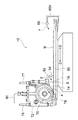
次に、ダイシング装置1の構成について説明する。図3は、切断装置10の形態を示す正面図であり、図4は、同じく平面図である。
Next, the configuration of the
ダイシング装置1の切断装置10は、図3、図4に示されるように、ブレード14、カッティングテーブル60、固定ウォーターカーテンノズル62、スポンジブロック64、及び移動ウォーターカーテンノズル66等から構成されている。
As shown in FIGS. 3 and 4, the
ブレード14は、図2に示されるモータ68のスピンドル70に取り付けられている。このモータ68が駆動されると、ブレード14は図3上矢印Aで示される方向に高速回転される。また、ブレード14は、図3に示されるフランジカバー72によって包囲されている。フランジカバー72は図4に示されるYキャリッジ74に固定され、このYキャリッジ74が図示しないY軸方向移動機構に連結されている。
The
フランジカバー72には、図3に示されるように、切削水供給ノズル76、及び冷却水供給ノズル78が設けられている。切削水供給ノズル76は、ブレード14に対向して配置され、この切削水供給ノズル76から図3上矢印B方向に噴射された切削水が、切断直前のブレード14に供給される。また、冷却水供給ノズル78は、ブレード14を挟んで一対設けられており、この冷却水供給ノズル78から噴射された冷却水が、切断中のブレード14及びウェーハWの切断部に供給され、ブレード14及び切断部が冷却される。
As shown in FIG. 3, the
なお、フランジカバー72には、切削水供給ノズル76に切削水を供給するチューブ77が接続されるとともに、冷却水供給ノズル78に冷却水を供給するチューブ79が接続されている。また、フランジカバー72には、ブレード14の磨耗、欠け等を非接触で検出するセンサが内蔵され、このセンサからの情報がケーブル80を介して図示しない制御装置に出力されるようになっている。
A
ところで、固定ウォーターカーテンノズル62、及びスポンジブロック64は図4に示されるように、ブレード14のX軸移動方向のうちD方向側(一方側)に配設されている。また、固定ウォーターカーテンノズル62、及びスポンジブロック64は、上下に近接して配置されるとともにカッティングテーブル60のX軸移動方向に対して直交する方向に配設されている。
Incidentally, as shown in FIG. 4, the fixed
更に、固定ウォーターカーテンノズル62は、この下方を通過するウェーハW全体に洗浄水を噴射することができ、スポンジブロック64は、この下方を通過するウェーハW全面をスクラブ洗浄できる長さに設定されている。また、固定ウォーターカーテンノズル62、及びスポンジブロック64は、Yキャリッジ74に連結されている。これによって、固定ウォーターカーテンノズル62、及びスポンジブロック64はブレード14とともにY軸方向に移動される。
Further, the fixed
固定ウォーターカーテンノズル62は、図示しない遮断弁を介して給水源に接続されている。また、固定ウォーターカーテンノズル62の下面には、ノズル62の軸方向に沿って多数の噴射孔(不図示)が形成されている。したがって、遮断弁が開放されると、給水源から圧送された洗浄水が噴射孔から噴射(噴霧)され、そして、噴射された洗浄水はカーテン状となってウェーハWの表面に供給される。この洗浄水によってウェーハWの表面に付着した汚水が洗い流され、汚水中の切り粉等が除去される。なお、遮断弁は、ウェーハWの切断加工中に常時開放されているので、ウェーハWは常に濡れた状態に保持される。これにより、ウェーハWの乾燥が防止されている。
The fixed
固定ウォーターカーテンノズル62の噴射孔から噴射される洗浄水の噴射方向は、ブレード14によって吹き飛ばされる切削水及び冷却水の吹き飛び方向に対して逆らわない方向に設定されている。これによって、固定ウォーターカーテンノズル62から噴射された洗浄水は、切削水及び冷却水で邪魔されることなく、ウェーハWに供給される。洗浄水の噴射方向は、図3及び図5上で矢印Eで示している。この方向Eは、切削水供給ノズル76から噴射される切削水の噴射方向Bと略同方向である。
The spraying direction of the cleaning water sprayed from the spray hole of the fixed
スポンジブロック64は、先端(下端)がウェーハWに接するように設けられるスクラブ洗浄手段である。スクラブ洗浄手段としてのスポンジブロック64は、ウェーハWに傷、スクラッチ等の欠陥を生じさせずに、ウェーハWの表面の汚染を除去できるものであれば、材質的な制限はないが、たとえば、PVAスポンジ(商品名:ベルクリン)のブロックが好ましく使用できる。
The
スポンジブロック64は、先端がウェーハWの全幅に亘ってもれなく接してスクラブ洗浄できるように、真直度が良好に形成されている、又は支持されていることが好ましい。また、スポンジブロック64の先端のウェーハWと接触する幅は、10mm以下であることが好ましい。
The
スポンジブロック64によるスクラブ洗浄の際には、スポンジブロック64に洗浄水が供給されていることが好ましいが、この洗浄水の供給は、後述する移動ウォーターカーテンノズル66によりなされる。
At the time of scrub cleaning by the
なお、スポンジブロック64の形態は、図示の例(たとえば、ベルクリンD3)に限定されるものではなく、他の形態、たとえば、PVAスポンジのシート(たとえば、ベルクリンD1)を小径のバックアップローラに巻き掛けた構成でウェーハWと接触させる等、各種の形態が採用できる。
The form of the
移動ウォーターカーテンノズル66は、カッティングテーブル60の右端部の斜め上方に固定されている。すなわち、カッティングテーブル60の右端部には断面コ字状の部材であるブラケット66Aの一端部が固定され、このブラケット66Aの他端部に移動ウォーターカーテンノズル66が取り付けられている。したがって、移動ウォーターカーテンノズル66は、カッティングテーブル60とともにX軸方向に移動される。
The moving
また、移動ウォーターカーテン66は、カッティングテーブル60のX軸移動方向に対して直交する方向に配設されている。更に、移動ウォーターカーテンノズル66は、ウェーハW全体に洗浄水を噴射することができる長さに設定されている。
Further, the moving
移動ウォーターカーテンノズル66は、図示しない遮断弁を介して給水源に接続されている。また、移動ウォーターカーテンノズル66の下面には、ノズル66の軸方向に沿って多数の噴射孔(不図示)が形成されている。したがって、遮断弁が開放されると、給水源から圧送された洗浄水が噴射孔から噴射(噴霧)され、そして、噴射された洗浄水はカーテン状となってウェーハWの表面に供給される。この洗浄水によってウェーハWの表面に付着した汚水が洗い流され、汚水中の切り粉等が除去される。なお、遮断弁は、ウェーハWの切断加工中に常時開放されているので、ウェーハWは常に濡れた状態に保持される。これにより、ウェーハWの乾燥が防止されている。
The moving
移動ウォーターカーテンノズル66の噴射孔から噴射される洗浄水の噴射方向は、ブレード14によって吹き飛ばされる切削水及び冷却水の吹き飛び方向に対して逆らわない方向に設定されている。これによって、移動ウォーターカーテンノズル66から噴射された洗浄水は、切削水及び冷却水で邪魔されることなく、ウェーハWに供給される。洗浄水の噴射方向は、図3及び図5上で矢印Fで示している。この方向Fは、切削水供給ノズル76から噴射される切削水の噴射方向Bと略同方向である。
The spraying direction of the cleaning water sprayed from the spray hole of the moving
次に、前記の如く構成された切断装置10の作用について説明する。先ず、図2の位置P2でウェーハWを吸着保持したカッティングテーブル60は、図3に示される切断開始位置まで移動され、その位置に待機される。そして、カッティングテーブル60を図3上矢印C方向に移動させることにより、ウェーハWの切断が開始される。図5は、切断中間の位置であり、図6は切断が終了したブレード14とカッティングテーブルと60の相対位置である。
Next, the operation of the cutting
ウェーハWの切断時において、切削水供給ノズル76からブレード14に向けて切削水が常時供給され、また、冷却水供給ノズル78からブレード14に、そして切断部に冷却水が常時供給されている。そして、固定ウォーターカーテンノズル62、及び移動ウォーターカーテンノズル66から、切断加工中のウェーハWに洗浄液が常時噴射されている。これにより、ウェーハWに付着した汚水が直ぐに洗い流されるとともにウェーハWの乾燥が防止されている。
At the time of cutting the wafer W, cutting water is constantly supplied from the cutting
この際、固定ウォーターカーテンノズル62から、切断加工中のウェーハWに洗浄液が噴射された場合、カッティングテーブル60の位置により、洗浄液が噴射されるウェーハWの部位が時々刻々異なり、たとえば、図6の状態では、ウェーハWの左端部近傍への洗浄液の噴射量が不足気味になる。
At this time, when the cleaning liquid is sprayed from the fixed
一方、移動ウォーターカーテンノズル66とウェーハWとの相対位置は常に一定であり、移動ウォーターカーテンノズル66から、切断加工中のウェーハWに洗浄液が噴射された場合、カッティングテーブル60の位置に拘らず洗浄液が噴射されるウェーハWの部位に変化はない。したがって、あらかじめ移動ウォーターカーテンノズル66の洗浄液の噴射方向Fを適正にセットしておくことにより、ウェーハWに洗浄液が常時噴射されている状態を維持できる。
On the other hand, the relative position between the moving
以上説明した切断装置10によれば、汚水によるウェーハW及びチップの汚染を防止することができる。また、ウェーハWの乾燥が防止されているので、切断加工後の洗浄装置20(図2参照)における洗浄時間を短縮することができる。よって、ウェーハWのスループットを向上させることができる。特に、本切断装置10は、大径のウェーハWに好適となる。
According to the cutting
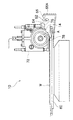
次に、本発明に係る洗浄装置20について説明する。図7は、ダイシング装置1の洗浄装置20の正面図であり、図8は、同じく平面図である。
Next, the
図7及び図8に示されるように、洗浄装置20では、図示しない洗浄槽内において、スピンテーブル47が不図示のモータによって回転される軸47Aに取付けられ、約500〜3,000rpmの速度で回転されるようになっている。
As shown in FIGS. 7 and 8, in the
スピンテーブル47にはダイシングシートSを介してウェーハWが吸着可能となっている。ウェーハWの上方には洗浄ノズル41が、上下調整手段42及び傾斜調整手段43を介してアーム44に取付けられている。アーム44はモータ46で一定角度往復回転される回転シャフト45に接続されている。
The wafer W can be attracted to the spin table 47 via the dicing sheet S. Above the wafer W, a cleaning
洗浄ノズル41は上下調整手段42によって適宜の高さに調整されるとともに、傾斜調整手段43によってウェーハWに対して傾斜して取付けできるようになっている。したがって、洗浄水の噴射中心が後述するスクラブスポンジ49と干渉しないように調整でき、必要に応じて、洗浄水の噴射中心とウェーハWの中心とが一致するように調整できる。
The cleaning
また、スクラブスポンジ49の調整や、ウェーハWの搬入・搬出の際に、図8に示されるように、洗浄ノズル41をウェーハWの上方より退避させることができ、更に、必要に応じて、洗浄ノズル41をウェーハWの周縁から中心を経由して反対側の周縁までの間を往復揺動させることもできる。
Further, when the
洗浄ノズル41としては、洗浄水の中に圧縮エアを供給して、水とエアとを混合して噴射する混合ノズル(2流体ノズル)であってもよく、洗浄水のみ噴射する1流体ノズルであってもよい。また、洗浄ノズル41として洗浄水に超音波を印加して噴射する超音波ノズルを採用することもできる。
The cleaning
スクラブスポンジ49は、先端(下端)がウェーハWに接するように設けられるスクラブ洗浄手段である。スクラブ洗浄手段としてのスクラブスポンジ49は、ウェーハWに傷、スクラッチ等の欠陥を生じさせずに、ウェーハWの表面の汚染を除去できるものであれば、材質的な制限はないが、たとえば、PVAスポンジ(商品名:ベルクリン)のブロックが好ましく使用できる。
The
スクラブスポンジ49は、先端がウェーハWの全幅に亘ってもれなく接してスクラブ洗浄できるように、真直度が良好に形成されている、又は支持されていることが好ましい。スクラブスポンジ49の支持手段の図示は省略するが、ウェーハWに接触する状態と、ウェーハWの上方へ退避した状態の2位置以上に可変とする構成が必要である。
The
スクラブスポンジ49の先端部分の長さは、ウェーハWの半径より長くなっていることが好ましい。このようなスクラブスポンジ49であれば、ウェーハWの表面の全面をカバーできる。また、スクラブスポンジ49の先端のウェーハWと接触する幅は、10mm以下であることが好ましい。
The length of the tip portion of the
スクラブスポンジ49によるスクラブ洗浄の際には、スクラブスポンジ49に洗浄水が供給されていることが好ましいが、この洗浄水の供給は、既述の洗浄ノズル41によりなされる。
At the time of scrub cleaning with the
なお、スクラブスポンジ49の形態は、図示の例(たとえば、ベルクリンD3)に限定されるものではなく、他の形態、たとえば、PVAスポンジのシート(たとえば、ベルクリンD1)を小径のバックアップローラに巻き掛けた構成でウェーハWと接触させる等、各種の形態が採用できる。
The form of the
次に、前記の如く構成された洗浄装置20の作用について説明する。先ず、スピンテーブル47にダイシングシートSを介してウェーハWを吸着保持させる。次いで、洗浄ノズル41より洗浄水を噴射させるとともに、スピンテーブル47を起動させ所定の回転数(たとえば、500rpm)まで増速させる。
Next, the operation of the
次いで、スクラブスポンジ49を下降させ、先端の全長がウェーハWと接触するようにスクラブ位置にセットする。この状態で所定時間スクラブ洗浄を行った後、スクラブスポンジ49を上方に退避させる。
Next, the
次いで、スピン洗浄に移る。このスピン洗浄では、洗浄水の噴射量、及びスピンテーブル47の回転数をスクラブ洗浄時と異ならせてもよく、スクラブ洗浄時と同一に維持させてもよい。 Then, it moves to spin cleaning. In this spin cleaning, the amount of cleaning water sprayed and the rotation speed of the spin table 47 may be different from those during scrub cleaning, or may be maintained the same as during scrub cleaning.
次いで、洗浄水の噴射を停止させ、スピン乾燥に移る。このスピン乾燥では、スピンテーブル47の回転数をスクラブ洗浄時より高く設定する(たとえば、3,000rpm)ことが好ましい。所定時間(たとえば、10分)のスピン乾燥で洗浄・乾燥工程が終了する。この後、スピンテーブル47よりウェーハWをアンロードさせる。 Next, the washing water jet is stopped and the process proceeds to spin drying. In this spin drying, it is preferable to set the rotation speed of the spin table 47 higher than that during scrub cleaning (for example, 3,000 rpm). The cleaning / drying process is completed by spin drying for a predetermined time (for example, 10 minutes). Thereafter, the wafer W is unloaded from the spin table 47.
以上説明した洗浄装置20によれば、従来タイプの洗浄方式に加え、ウェーハWの表面に当接されながらウェーハWの表面を洗浄するスクラブスポンジ49が設けられているので、ダイシング加工後のウェーハWに対して有効なコンタミ除去を行うことができる。
According to the
以上、本発明に係る洗浄装置及び該洗浄装置を備えるダイシング装置の実施形態について説明したが、本発明は上記実施形態に限定されるものではなく、各種の態様が採り得る。 As mentioned above, although embodiment of the washing | cleaning apparatus which concerns on this invention, and a dicing apparatus provided with this washing | cleaning apparatus was described, this invention is not limited to the said embodiment, Various aspects can be taken.
たとえば、本実施形態においては、スクラブ洗浄手段としてのスクラブスポンジ49として、棒状の固定部材が採用されているが、これに代えてローラ状のスポンジ部材を使用してもよく、本実施形態と同様の効果が得られる。この場合、ローラ状スポンジ部材は、回転駆動させてもよく、従動状態に支持してもよい。
For example, in the present embodiment, a rod-shaped fixing member is employed as the
また、本実施形態においては、洗浄水を噴射(噴霧)してウェーハWに供給したが、シャワー状、又はスプレー状にして供給してもよい。 In this embodiment, the cleaning water is sprayed (sprayed) and supplied to the wafer W. However, the cleaning water may be supplied in the form of a shower or spray.
更に、本実施形態においては、半導体ウェーハを切断するダイシング装置について説明したが、被加工材の適用対象は半導体ウェーハに限定されるものではなく、切断しながら洗浄することを必要とする被加工材(たとえば、液晶セル等)であれば、本発明を適用することができる。 Furthermore, in this embodiment, although the dicing apparatus which cut | disconnects a semiconductor wafer was demonstrated, the application object of a workpiece is not limited to a semiconductor wafer, The workpiece which needs to wash | clean while cut | disconnecting The present invention can be applied to any device (for example, a liquid crystal cell).
図1等に示されるダイシング装置1を使用してシリコンウェーハのダイシング処理を行った。
Dicing processing of the silicon wafer was performed using the
ウェーハWとしては、外径が100mm(公称4インチサイズ)のシリコンウェーハ(厚さ2mm)を使用した。ブレード14の外径は56mmであり、回転数は30,000rpmである。X方向の研削送り速度は5mm/秒とした。
As the wafer W, a silicon wafer (thickness 2 mm) having an outer diameter of 100 mm (nominal 4 inch size) was used. The outer diameter of the
スクラブスポンジ49として、既述のベルクリンD3を使用した。スクラブスポンジ49の幅は、80mmとした。
As the
スクラブ洗浄時(10分)の洗浄水の噴射量を2リットル/分とし、スピンテーブル47の回転数を200rpmとした。スピン洗浄時(10分)の洗浄水の噴射量を2リットル/分とし、スピンテーブル47の回転数を200rpmとした。スピン乾燥時(10分)のスピンテーブル47の回転数を3,000rpmとした。 The amount of cleaning water sprayed during scrub cleaning (10 minutes) was 2 liters / minute, and the rotation speed of the spin table 47 was 200 rpm. The amount of cleaning water sprayed at the time of spin cleaning (10 minutes) was 2 liters / minute, and the rotation speed of the spin table 47 was 200 rpm. The rotation speed of the spin table 47 during spin drying (10 minutes) was set to 3,000 rpm.
洗浄・乾燥後のシリコンウェーハ(チップ)の表面を光学顕微鏡(倍率:50倍及び200倍)により観察(撮像)し、汚染の状態を評価した。 The surface of the cleaned and dried silicon wafer (chip) was observed (imaged) with an optical microscope (magnification: 50 times and 200 times) to evaluate the state of contamination.
実施例として、スクラブスポンジ49を使用してスクラブ洗浄を行った。
As an example, scrub cleaning was performed using a
比較例として、スクラブスポンジ49を使用しないで同じ時間だけ洗浄水の噴射による洗浄を行った。
As a comparative example, cleaning was performed by spraying cleaning water for the same time without using the
実施例においては、乾燥後のシリコンウェーハ(N=5点)の表面に汚染は認められなかった。 In the examples, no contamination was observed on the surface of the dried silicon wafer (N = 5 points).
比較例においては、乾燥後のシリコンウェーハ(N=5点)の表面のほぼ全面に汚染が認められた。 In the comparative example, contamination was observed on almost the entire surface of the dried silicon wafer (N = 5 points).
以上の結果より、本実施例の顕著な効果が確認できた。 From the above results, the remarkable effect of the present example was confirmed.
1…ダイシング装置、10…切断装置、14…ブレード、20…洗浄装置、60…カッティングテーブル、41…洗浄ノズル、47…スピンテーブル、49…スクラブスポンジ、72…フランジカバー、76…切削水供給ノズル、78…冷却水供給ノズル、W…ウェーハ
DESCRIPTION OF
Claims (5)
被洗浄材を支持しながら回転駆動されるスピンテーブルと、
先端部分が被洗浄材に接離可能となるように装置本体に支持されており、被洗浄材の表面に当接されながら該被洗浄材の表面を洗浄するスクラブ洗浄手段と、
が設けられていることを特徴とする洗浄装置。 Cleaning water jetting means for jetting cleaning water toward the material to be cleaned;
A spin table that is driven to rotate while supporting the material to be cleaned;
A scrub cleaning means that is supported by the apparatus main body so that the tip portion can be contacted and separated from the material to be cleaned, and that cleans the surface of the material to be cleaned while being in contact with the surface of the material to be cleaned;
Is provided.
A cutting device that rotationally drives a cutting blade, and a support table that supports the workpiece and is moved relative to the cutting device, and is provided at a stage subsequent to dicing means for performing a dicing process on the workpiece. A dicing apparatus, wherein the cleaning apparatus according to any one of -4 is provided.
Priority Applications (1)
| Application Number | Priority Date | Filing Date | Title |
|---|---|---|---|
| JP2006010317A JP2007194367A (en) | 2006-01-18 | 2006-01-18 | Washing apparatus, and dicing equipment provided therewith |
Applications Claiming Priority (1)
| Application Number | Priority Date | Filing Date | Title |
|---|---|---|---|
| JP2006010317A JP2007194367A (en) | 2006-01-18 | 2006-01-18 | Washing apparatus, and dicing equipment provided therewith |
Publications (1)
| Publication Number | Publication Date |
|---|---|
| JP2007194367A true JP2007194367A (en) | 2007-08-02 |
Family
ID=38449828
Family Applications (1)
| Application Number | Title | Priority Date | Filing Date |
|---|---|---|---|
| JP2006010317A Pending JP2007194367A (en) | 2006-01-18 | 2006-01-18 | Washing apparatus, and dicing equipment provided therewith |
Country Status (1)
| Country | Link |
|---|---|
| JP (1) | JP2007194367A (en) |
Cited By (10)
| Publication number | Priority date | Publication date | Assignee | Title |
|---|---|---|---|---|
| KR101097516B1 (en) | 2009-09-30 | 2011-12-22 | 윤점채 | A cleaning system in semiconductor equipments |
| JP2013115278A (en) * | 2011-11-29 | 2013-06-10 | Tokyo Seimitsu Co Ltd | Supply device and supply method of cleaning solution |
| KR101336960B1 (en) * | 2011-09-26 | 2013-12-04 | 주식회사 세운티.엔.에스 | Fiberglass insulation with water-jet cutting device |
| WO2014027516A1 (en) * | 2012-08-17 | 2014-02-20 | 株式会社プレテック | Immersion-type cleaning device |
| JP2014143322A (en) * | 2013-01-24 | 2014-08-07 | Disco Abrasive Syst Ltd | Cleaning device and cleaning method |
| KR20150114428A (en) * | 2014-04-01 | 2015-10-12 | 가부시키가이샤 에바라 세이사꾸쇼 | Cleaning apparatus and cleaning method |
| CN105551996A (en) * | 2014-10-22 | 2016-05-04 | 东和株式会社 | Cutting device and cutting method |
| WO2021132133A1 (en) * | 2019-12-26 | 2021-07-01 | ヤマハロボティクスホールディングス株式会社 | Semiconductor chip cleaning method and semiconductor chip cleaning device |
| CN114536226A (en) * | 2022-03-29 | 2022-05-27 | 武汉江丰电子材料有限公司 | Rotary target material sand blasting cleaning system device, sand blasting cleaning method and application |
| WO2024041321A1 (en) * | 2022-08-23 | 2024-02-29 | Tcl Zhonghuan Renewable Energy Technology Co., Ltd. | Devices for automatic cleaning of a monocrystalline silicon bar |
Citations (7)
| Publication number | Priority date | Publication date | Assignee | Title |
|---|---|---|---|---|
| JPS61181134A (en) * | 1985-02-07 | 1986-08-13 | Hitachi Ltd | Cleansing apparatus |
| JPS62114228A (en) * | 1985-11-13 | 1987-05-26 | Nec Kansai Ltd | Manufacture of semiconductor |
| JPH01287808A (en) * | 1988-05-16 | 1989-11-20 | Hitachi Ltd | Precision cleaning equipment |
| JPH065576A (en) * | 1992-06-19 | 1994-01-14 | Komatsu Denshi Kinzoku Kk | Method and device for cleaning plate to which wafer is attached |
| JPH07240452A (en) * | 1994-02-28 | 1995-09-12 | Seiko Seiki Co Ltd | Processing machine for semiconductor wafer |
| JPH11179299A (en) * | 1997-12-25 | 1999-07-06 | Toray Ind Inc | Cleaner |
| JP2001007069A (en) * | 1999-06-17 | 2001-01-12 | Ebara Corp | Substrate cleaner |
-
2006
- 2006-01-18 JP JP2006010317A patent/JP2007194367A/en active Pending
Patent Citations (7)
| Publication number | Priority date | Publication date | Assignee | Title |
|---|---|---|---|---|
| JPS61181134A (en) * | 1985-02-07 | 1986-08-13 | Hitachi Ltd | Cleansing apparatus |
| JPS62114228A (en) * | 1985-11-13 | 1987-05-26 | Nec Kansai Ltd | Manufacture of semiconductor |
| JPH01287808A (en) * | 1988-05-16 | 1989-11-20 | Hitachi Ltd | Precision cleaning equipment |
| JPH065576A (en) * | 1992-06-19 | 1994-01-14 | Komatsu Denshi Kinzoku Kk | Method and device for cleaning plate to which wafer is attached |
| JPH07240452A (en) * | 1994-02-28 | 1995-09-12 | Seiko Seiki Co Ltd | Processing machine for semiconductor wafer |
| JPH11179299A (en) * | 1997-12-25 | 1999-07-06 | Toray Ind Inc | Cleaner |
| JP2001007069A (en) * | 1999-06-17 | 2001-01-12 | Ebara Corp | Substrate cleaner |
Cited By (18)
| Publication number | Priority date | Publication date | Assignee | Title |
|---|---|---|---|---|
| KR101097516B1 (en) | 2009-09-30 | 2011-12-22 | 윤점채 | A cleaning system in semiconductor equipments |
| KR101336960B1 (en) * | 2011-09-26 | 2013-12-04 | 주식회사 세운티.엔.에스 | Fiberglass insulation with water-jet cutting device |
| JP2013115278A (en) * | 2011-11-29 | 2013-06-10 | Tokyo Seimitsu Co Ltd | Supply device and supply method of cleaning solution |
| WO2014027516A1 (en) * | 2012-08-17 | 2014-02-20 | 株式会社プレテック | Immersion-type cleaning device |
| JP2014143322A (en) * | 2013-01-24 | 2014-08-07 | Disco Abrasive Syst Ltd | Cleaning device and cleaning method |
| US11164758B2 (en) | 2014-04-01 | 2021-11-02 | Ebara Corporation | Washing device and washing method |
| KR102314682B1 (en) * | 2014-04-01 | 2021-10-20 | 가부시키가이샤 에바라 세이사꾸쇼 | Cleaning apparatus and cleaning method |
| KR20150114428A (en) * | 2014-04-01 | 2015-10-12 | 가부시키가이샤 에바라 세이사꾸쇼 | Cleaning apparatus and cleaning method |
| US11837477B2 (en) | 2014-04-01 | 2023-12-05 | Ebara Corporation | Washing device and washing method |
| CN105551996A (en) * | 2014-10-22 | 2016-05-04 | 东和株式会社 | Cutting device and cutting method |
| JP2016082195A (en) * | 2014-10-22 | 2016-05-16 | Towa株式会社 | Cutting device and cutting method |
| KR101793337B1 (en) * | 2014-10-22 | 2017-11-20 | 토와 가부시기가이샤 | Cutting device and cutting method |
| WO2021132133A1 (en) * | 2019-12-26 | 2021-07-01 | ヤマハロボティクスホールディングス株式会社 | Semiconductor chip cleaning method and semiconductor chip cleaning device |
| JPWO2021132133A1 (en) * | 2019-12-26 | 2021-07-01 | ||
| TWI768613B (en) * | 2019-12-26 | 2022-06-21 | 日商雅馬哈發動機智能機器控股股份有限公司 | Semiconductor wafer cleaning method and semiconductor wafer cleaning device |
| JP7444410B2 (en) | 2019-12-26 | 2024-03-06 | ヤマハロボティクスホールディングス株式会社 | Semiconductor chip cleaning method and semiconductor chip cleaning device |
| CN114536226A (en) * | 2022-03-29 | 2022-05-27 | 武汉江丰电子材料有限公司 | Rotary target material sand blasting cleaning system device, sand blasting cleaning method and application |
| WO2024041321A1 (en) * | 2022-08-23 | 2024-02-29 | Tcl Zhonghuan Renewable Energy Technology Co., Ltd. | Devices for automatic cleaning of a monocrystalline silicon bar |
Similar Documents
| Publication | Publication Date | Title |
|---|---|---|
| JP2007194367A (en) | Washing apparatus, and dicing equipment provided therewith | |
| KR101277614B1 (en) | Substrate processing apparatus and substrate processing method | |
| US5868866A (en) | Method of and apparatus for cleaning workpiece | |
| KR102142893B1 (en) | Method of polishing back surface of substrate and substrate processing apparatus | |
| US20020007840A1 (en) | Substrate cleaning apparatus, substrate cleaning method and substrate processing apparatus | |
| JP4777072B2 (en) | Dicing machine | |
| JP2001246331A (en) | Cleaning device | |
| JP2006344878A (en) | Processing apparatus and processing method | |
| JP6054805B2 (en) | Substrate cleaning device | |
| TW201330148A (en) | Substrate cleaning method and substrate cleaning device | |
| US20160074988A1 (en) | Processing module, processing apparatus, and processing method | |
| JP2016058724A (en) | Processing module, processor, and processing method | |
| JP2009160700A (en) | Polishing device | |
| JP7290695B2 (en) | Cleaning equipment for ultrasonic cleaning equipment and cleaning tools | |
| JP4721968B2 (en) | Spinner cleaning device | |
| JP2020184581A (en) | Substrate processing apparatus and substrate processing method | |
| JP5389473B2 (en) | Spinner cleaning device | |
| WO2021044694A1 (en) | Polishing device, polishing method and substrate processing device | |
| JP2011031359A (en) | Polishing tool, polishing device, and polishing machining method | |
| JP2007194612A (en) | Semiconductor device or manufacturing method for semiconductor wafer | |
| JP2015044250A (en) | Polishing method | |
| JP4295469B2 (en) | Polishing method | |
| JP2022157038A (en) | Machining device | |
| JP2017174940A (en) | Polishing device and polishing method | |
| JP2015044251A (en) | Polishing method |
Legal Events
| Date | Code | Title | Description |
|---|---|---|---|
| A621 | Written request for application examination |
Free format text: JAPANESE INTERMEDIATE CODE: A621 Effective date: 20081212 |
|
| A977 | Report on retrieval |
Effective date: 20100831 Free format text: JAPANESE INTERMEDIATE CODE: A971007 |
|
| A131 | Notification of reasons for refusal |
Effective date: 20100909 Free format text: JAPANESE INTERMEDIATE CODE: A131 |
|
| A521 | Written amendment |
Effective date: 20101105 Free format text: JAPANESE INTERMEDIATE CODE: A523 |
|
| A131 | Notification of reasons for refusal |
Effective date: 20110414 Free format text: JAPANESE INTERMEDIATE CODE: A131 |
|
| A02 | Decision of refusal |
Free format text: JAPANESE INTERMEDIATE CODE: A02 Effective date: 20111003 |