JP2007185237A - Washing machine - Google Patents
Washing machine Download PDFInfo
- Publication number
- JP2007185237A JP2007185237A JP2006003716A JP2006003716A JP2007185237A JP 2007185237 A JP2007185237 A JP 2007185237A JP 2006003716 A JP2006003716 A JP 2006003716A JP 2006003716 A JP2006003716 A JP 2006003716A JP 2007185237 A JP2007185237 A JP 2007185237A
- Authority
- JP
- Japan
- Prior art keywords
- washing machine
- wiring board
- back side
- wall
- substrate support
- Prior art date
- Legal status (The legal status is an assumption and is not a legal conclusion. Google has not performed a legal analysis and makes no representation as to the accuracy of the status listed.)
- Granted
Links
Images


Landscapes
- Main Body Construction Of Washing Machines And Laundry Dryers (AREA)
Abstract
Description
本発明は、電装品を操作する操作部材を、パネル部材の開口部を貫通するように設けた構成の洗濯機に関する。 The present invention relates to a washing machine having a configuration in which an operation member for operating an electrical component is provided so as to penetrate an opening of a panel member.
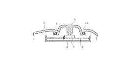
この種の従来構成の例を図10及び図11に示す。まず、図10に示す第1の従来例は、次のような構成となっている。洗濯機本体に設けられるパネル部材1には開口部1aが形成され、パネル部材1の裏側には、配線基板2を支持する基板支持部材3が配設されている。配線基板2上には、例えばタイマーからなる電装品4が配設されていて、この電装品4は、開口部1aを貫通するように設けられた操作部材5により回転操作される構成となっている。そして、開口部1aの内周部と操作部材5の外周部との間には、防水用のシール部材6が設けられていて、それら開口部1aの内周部と操作部材5の外周部との間から配線基板2側へ水が浸入することを防止する構成となっている。
An example of this type of conventional configuration is shown in FIGS. First, the first conventional example shown in FIG. 10 has the following configuration. An opening 1 a is formed in the
一方、図11に示す第2の従来例は、電装品7として防水タイプの独立した構成のものを使用し、この電装品7を、パネル部材1の裏側にねじ止めした構成としている(例えば、特許文献1参照)。
第1の従来例のものの場合、パネル部材1の開口部1aと操作部材5との間にシール部材6を設けているので、操作部材5を操作する際の操作感を悪くするという問題点がある。また、第2の従来例のものの場合、電装品7が防水タイプとした特別なものとなり、コストが高くなるという問題点がある。
In the case of the first conventional example, since the seal member 6 is provided between the opening 1a of the
本発明は上記した事情に鑑みてなされたものであり、その目的は、操作部材の操作感を悪くすることを防止でき、また、防水対策を安価な構成にて達成することができる洗濯機を提供するにある。 The present invention has been made in view of the above-described circumstances, and an object of the present invention is to provide a washing machine that can prevent the operation feeling of the operation member from being deteriorated and can achieve waterproof measures with an inexpensive configuration. In offer.
上記した目的を達成するために、本発明の洗濯機は、洗濯機本体に設けられ、開口部を有するパネル部材と、このパネル部材の裏側に配設された基板支持部材と、この基板支持部材に支持された配線基板と、前記開口部にこれを貫通するように設けられた操作部材と、前記配線基板に設けられ、前記操作部材によって操作される電装品と、前記基板支持部材に設けられ、前記操作部材及び前記電装品を囲むように設けられた囲い壁と、前記基板支持部材において前記囲い壁の内側に位置させて設けられた排水口とを備え、前記開口部の内周部と前記操作部材の外周部との間の隙間から前記パネル部材の裏側へ浸入した水を、前記排水口から前記基板支持部材の裏側へ排出する構成としたことを特徴とする。 In order to achieve the above object, a washing machine of the present invention is provided with a panel member having an opening, a substrate support member disposed on the back side of the panel member, and the substrate support member. A wiring board supported on the opening, an operation member provided to penetrate the opening, an electrical component provided on the wiring board and operated by the operation member, and provided on the board support member. An enclosure wall provided so as to surround the operation member and the electrical component, and a drain outlet provided in the substrate support member so as to be positioned inside the enclosure wall, and an inner peripheral portion of the opening Water that has entered the back side of the panel member from the gap between the outer peripheral portion of the operation member is discharged from the drain port to the back side of the substrate support member.
本発明によれば、開口部と操作部材との間の隙間からパネル部材の裏側へ水が浸入した場合、その水は、基板支持部材に設けられた排水口から基板支持部材の裏側へ排出される構成となっているので、電装品に水が掛かることを防止できる。この場合、開口部と操作部材との間に防水用のシール部材を設ける必要がないため、操作部材の操作感を悪くすることを防止できる。また、電装品に、防水タイプのような特別なものを用いる必要がなく、防水対策を安価な構成にて達成することができる。 According to the present invention, when water enters the back side of the panel member from the gap between the opening and the operation member, the water is discharged from the drain port provided in the substrate support member to the back side of the substrate support member. Therefore, it is possible to prevent water from splashing on the electrical components. In this case, since it is not necessary to provide a waterproof seal member between the opening and the operation member, it is possible to prevent the operation feeling of the operation member from being deteriorated. In addition, it is not necessary to use a special type of electrical component such as a waterproof type, and waterproof measures can be achieved with an inexpensive configuration.
(第1の実施形態)
以下、本発明を、乾燥機能も有するドラム式洗濯機に適用した第1の実施形態を図1ないし図8を参照して説明する。
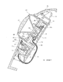
まず、図2及び図3において、洗濯機本体11の外殻を構成する外箱12の前面(図2及び図3の左側)のほぼ中央部には、洗濯物出入口13が形成されていると共に、この洗濯物出入口13を開閉する扉14が回動可能に設けられている。外箱12の内部には、水槽15が防振ダンパー16を介して配設されている。外箱12の底部には台板12aが設けられている。水槽15は、前面側が開口し、かつ後面が閉塞されたほぼ円筒状をなしていて、軸方向が横向きで、前部側が高くなるように傾斜した前上がりの傾斜状に配置されている。この水槽15の前面の開口部は、ベローズ17を介して洗濯物出入口13に連通している。
(First embodiment)
Hereinafter, a first embodiment in which the present invention is applied to a drum-type washing machine having a drying function will be described with reference to FIGS.
First, in FIGS. 2 and 3, a
水槽15の内部には、ドラム18が回転可能に配設されている。このドラム18も前面側が開口し、かつ後面が閉塞されたほぼ円筒状をなしていて、軸方向が横向きで、前部側が高くなるように傾斜した前上がりの傾斜状に配置されている。このドラム18には、通水及び通風が可能な孔19が多数形成されていると共に、内周部にバッフル20が複数個(図3には1個のみ示されている)設けられていている。ドラム18の前面開口部は、洗濯物出入口13に連通している。ドラム18は、洗濯物出入口13から投入された洗濯物を収容するようになっていて、洗濯槽と脱水槽を兼ねると共に、乾燥時の槽としても機能する。水槽15の背面部のほぼ中央部には、ドラム駆動用のモータ21が設けられている。このモータ21は、外転形のDCブラシレスモータから構成されていて、ロータ22に直結された回転軸23を介してドラム18を直接回転駆動する構成となっている。
A
水槽15の背面から上部にかけては、乾燥機構25が設けられている。乾燥機構25は、水冷式の熱交換器26と、送風機27と、ヒータ28を有する加熱装置29と、水槽15の内部と連通する循環風路30とを備えている。この乾燥機構25は、乾燥運転時に、水槽15内の空気(ドラム18内の空気)を循環風路30を介して循環させ、その過程でヒータ28により加熱して温風化し、その温風によりドラム18内の洗濯物を加熱して湿気を奪い、熱交換器26において湿気を凝縮させて除湿することにより、洗濯物を乾燥させるようになっている。
A
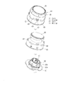
さて、外箱12の前面の上部の右側には、操作パネルユニット35が設けられている。この操作パネルユニット35の表面を構成するパネル部材36は、合成樹脂により形成されている。このパネル部材36には、図4にも示すように、電源の入り、切りを行なうための電源操作部37,38、洗濯、洗濯及び乾燥、乾燥のみを選択する選択操作部39,40,41、コース表示部42、液晶パネル43、洗い、すすぎ、脱水、乾燥をマニュアルで設定するための設定ボタン44a〜44dなどが設けられている。また、このパネル部材36には、選択操作部39,40,41とコース表示部42との間に位置させて、円形の開口部45(図1参照)が形成されていて、この開口部45内に、操作部材ユニット46が設けられている。操作部材ユニット46は、円筒状をなし回転操作が可能で、操作部材を構成するダイヤル48と、このダイヤル48の内側に押圧操作可能に配設され、第2の操作部材を構成する押釦49とを備えている。
An
この場合、ダイヤル48は、電装品であるロータリエンコーダ50を操作するためのものであり、そのロータリエンコーダ50の回転操作に基づきコース表示部42の表示が順次切り替わる構成となっている。また、押釦49は、電装品であるタクトスイッチ51を操作するためのものであり、スタートと一時停止の操作を兼ねている。操作パネルユニット35の下側には、前記扉14を開放させるための扉開放ボタン52が設けられている。また、パネル部材36において、操作部材ユニット46の下側でかつ扉開放ボタン52の近傍に位置させて、ドアロック表示部53が設けられている。
In this case, the
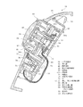
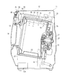
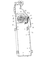
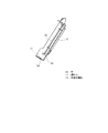
パネル部材36は、図1に示すように下部が前方へ出るように傾斜していて、その裏側に合成樹脂製の基板支持部材54がねじ55により取付固定されている。この基板支持部材54の上面側の周囲部には、図5及び図6に示すように壁56が枠状に設けられていて、その内部に第1の配線基板57が支持された状態で配設されている。また、基板支持部材54においてパネル部材36の開口部45に対応する部分には、操作部材ユニット46(ダイヤル48及びロータリエンコーダ50)を囲うように囲い壁58が設けられている。この囲い壁58は、下部側が開口部45に沿うような円弧状をなし、上部が上記壁56に連結されていて、前方から見てほぼU字形に形成されている。
As shown in FIG. 1, the
囲い壁58の上面側の開口部58aは、パネル部材36の開口部45よりも大きくなるように形成されていて、パネル部材36の開口部45の周縁部が、囲い壁58の開口部58aより内側へ突出している。囲い壁58の下部側の上端部にはシート状の防水部材59が接着されていて、この防水部材59が、囲い壁58の上端部とパネル部材36の裏面との間に挟まれた状態となっている。
The opening 58 a on the upper surface side of the surrounding
また、基板支持部材54において、囲い壁58の内側に位置させて、短円筒状をなす第2の囲い壁60が設けられていて、この第2の囲い壁60の内側に第2の配線基板61が支持された状態で配設されている。この第2の配線基板61上には、図6及び図8(c)にも示すように、ほぼ中央部に上記タクトスイッチ51が設けられ、その周囲にロータリエンコーダ50が設けられている。ロータリエンコーダ50の固定部50aは第2の配線基板61に固定され、回転部50bはその固定部50aに対して回転可能に設けられている。
Further, in the
上記押釦49の裏側には弾性変形が可能な押圧部材65が設けられていて、押釦49の押圧操作に伴い、その押圧部材65を介してタクトスイッチ51が押圧操作されるようになっている。ロータリエンコーダ50の回転部50bの外周部には、カバー部材を兼ねる回転伝達部材66が回転部50bと一体に回転するように取り付けられている。この回転伝達部材66は、第2の囲い壁60を開口部45側から覆う覆い部66aを有していて、その覆い部66aの後端部が第2の囲い壁60の外側に配置されている。
A pressing
回転伝達部材66の外周部には、図8(b)に示すように、複数個の係合孔67と、複数個の嵌合凹部68が形成されている。上記ダイヤル48の後ろ側には、複数個の係合爪69と、複数個の嵌合凸部70とが設けられている。そして、ダイヤル48と回転伝達部材66とは、図8(a)に示すように、各係合爪69と各係合孔67とを係合させると共に、各嵌合凸部70と各嵌合凹部68とを嵌合させることにより、一体に回転するように連結されている。したがって、ダイヤル48が回転操作されると、その回転が回転伝達部材66を介してロータリエンコーダ50の回転部50bに伝達されて当該回転部50bが回転する構成となっている。
As shown in FIG. 8B, a plurality of engagement holes 67 and a plurality of
上記基板支持部材54において、囲い壁58の内側のうちの下部、換言すれば囲い壁58と第2の囲い壁60との間のうちの下部に位置させて、貫通孔からなる排水口72が形成されている。また、基板支持部材54において、第2の囲い壁60の内側のうちの下部に位置させて、貫通孔からなる第2の排水口73が形成されている。
第1の配線基板57において、上記ドアロック表示部53の裏側に位置させて、LEDからなる表示素子74がLED支え75を介して設けられている。なお、第1の配線基板57には、上記電源操作部37,38、選択操作部39,40,41、コース表示部42、設定ボタン44a〜44dの裏側に位置させて、図示はしないが、それらに対応するスイッチや表示素子が実装されていると共に、液晶パネル43などが実装されている。
In the
In the
第2の囲い壁60の内側に配置された第2の配線基板61と、囲い壁58の外側に配置された第1の配線基板57との間を電気的に接続する電線76は、図1、図5及び図6に示すように、第2の排水口73を通り、基板支持部材54の下部を通して配線している。基板支持部材54の外周部の壁56において、操作部材ユニット46の近傍の下部には、図5ないし図7に示すように、他の部分より厚さを薄くした薄肉部77が形成されている。
An
ここで、基板支持部材54に配設される第1の配線基板57は、スイッチなどの電装品を実装した状態で、防湿用樹脂78(図7の二点鎖線参照)により防湿処理される。そして、防湿処理後、壁56から上記薄肉部77部分を切り離すことにより、壁56の下部に排水用の開口部を形成できる構成となっている。なお、基板支持部材54の裏側には、図3に示すように、裏カバー79が設けられている。
Here, the
上記構成において、例えば操作パネルユニット35のパネル部材36部分に水が掛かるなどして、開口部45の内周部とダイヤル48の外周部との間の隙間からパネル部材36の裏側へ水が浸入した場合、その水は、囲い壁58により排水口72へ導かれ、その排水口72から基板支持部材54の裏側へ排出される(図1の点線矢印A1参照)。このとき、囲い壁58により当該囲い壁58の内側と外側とが仕切られているから、開口部45の内周部とダイヤル48の外周部との間の隙間からパネル部材36の裏側へ浸入した水が、囲い壁58の外側に配置された第1の配線基板57側へ浸入することが阻止される。また、囲い壁58の内側には回転伝達部材66及び第2の囲い壁60があり、これら回転伝達部材66及び第2の囲い壁60が電装品であるロータリエンコーダ50、タクトスイッチ51及び第2の配線基板61を囲むように位置しているので、上記隙間からパネル部材36の裏側へ浸入した水が、それらロータリエンコーダ50、タクトスイッチ51及び第2の配線基板61に掛かることも防止できる。
In the above configuration, for example, water is applied to the
また、仮にダイヤル48の内周部と押釦49の外周部との間の隙間から押釦49の裏側へ水が浸入したとしても、その水は、回転伝達部材66の覆い部66aにより排水口72へ導かれ、その排水口72から基板支持部材54の裏側へ排出されるので、この場合もロータリエンコーダ50、タクトスイッチ51及び第2の配線基板61に掛かることを防止できる。
なお、排水口72から基板支持部材54の裏側へ排出された水は、図3に点線矢印A2で示すように、裏カバー79、ベローズ17の外周部を通り、水槽15の下部外面から台板12a側へ落下して排出される。
Even if water enters the back side of the
Note that the water discharged from the
上記した実施例においては、次のような作用効果を得ることができる。まず、パネル部材36の開口部45の内周部とダイヤル48の外周部との間の隙間からパネル部材36の裏側へ水が浸入した場合、その水は、基板支持部材54に設けられた排水口72から基板支持部材54の裏側へ排出される構成となっているので、第1及び第2の配線基板57,61、ロータリエンコーダ50、タクトスイッチ51などに水が掛かることを防止できる。この場合、開口部45とダイヤル48との間に防水用のシール部材を設ける必要がないため、ダイヤル48の操作感を悪くすることを防止できる。また、電装品であるロータリエンコーダ50やタクトスイッチ51に、防水タイプのような特別なものを用いる必要がなく、防水対策を安価な構成にて達成することができる。
In the embodiment described above, the following operational effects can be obtained. First, when water enters the back side of the
ダイヤル48の下側に位置させて囲い壁48及び排水口72を形成して、その排水口72から排水可能な構成としているので、ダイヤル48の下方近傍に、表示素子74を設けることができる。
Since the surrounding
基板支持部材54において、囲い壁58よりも内側に位置させて、電装品であるロータリエンコーダ50やタクトスイッチ51を囲むように設けられた第2の囲い壁60と、この第2の囲い壁60の内側に位置させて設けられた第2の排水口73とを備えた構成としているので、万一第2の囲い壁60の内側に水が浸入したとしても、その水を第2の排水口73から基板支持部材54の裏側へ排出させることができる。
In the
第2の囲い壁60の内側に配置された第2の配線基板61と、囲い壁の58の外側に配置された第1の配線基板57との間を電気的に接続する電線76を、第2の排水口73を通り、基板支持部材54の下部を通して配線していて、電線76を、第2の配線基板61から下方に向かって配線することができる。したがって、水がその電線76を伝って第2の配線基板61側へ浸入することを防止できる。
An
押釦49の裏側に第2の囲い壁60を開口部45側から覆うように設けられたカバー部材を兼ねる回転伝達部材66を備えているので、ダイヤル48の内周部と押釦49の外周部との間の隙間から押釦49の裏側へ水が浸入したとしても、その水を、回転伝達部材66の外面を介して囲い壁58と第2の囲い壁60との間の排水口72から基板支持部材54の裏側へ排出することができる。
Since the
ダイヤル48と、ロータリエンコーダ50の回転部50bと一体に回転する回転伝達部材66とを、係合爪69と係合孔67による係合と、嵌合凸部70とこれと嵌合する嵌合凹部68との嵌合とにより連結する構成としたので、軸方向のがたつきと、回転方向(円周方向)のがたつきとを抑えることができる。
基板支持部材54は、防湿用樹脂78により防湿処理される第1の配線基板57を囲む壁56を有していて、この壁56の下部に、切離可能な薄肉部77を形成しているので、防湿処理後、その薄肉部77を壁56から切り離すことにより、そこに排水用の開口部を形成することができる。
The
The
(第2の実施形態)
図9は本発明の第2の実施形態を示したものであり、この第2の実施形態は上記した第1の実施形態とは次の点が異なっている。
すなわち、操作部材ユニット85において、第2の配線基板61のほぼ中央部には、タクトスイッチ51に代えて、LEDからなる発光素子86を設けている。ダイヤル48の内側には、押釦49に代えて、透光性を有する透光部材87を設けていると共に、この透光部材87の裏側に、前上方に向けて拡開したLED支え88が設けられている。この場合、透光部材87は、LED支え88を介して第2の配線基板61に固定されている。
上記構成において、発光素子86が点灯すると、その発光素子86により透光部材87が照明される。
(Second Embodiment)
FIG. 9 shows a second embodiment of the present invention. This second embodiment differs from the first embodiment described above in the following points.
That is, in the
In the above configuration, when the
(他の実施形態)
本発明は、上記した各実施形態にのみ限定されるものではなく、次のように変形または拡張できる。
ドラム18の軸方向が横方向を指向したドラム式洗濯機に限られず、洗濯槽及び脱水槽を兼ねる回転槽の軸方向が上下方向に指向する縦軸形の洗濯機にも適用できる。
ダイヤル48により操作される電装品としては、ロータリエンコーダ50に限らず、タイマーでもよい。
(Other embodiments)
The present invention is not limited to the above embodiments, and can be modified or expanded as follows.
The present invention is not limited to a drum-type washing machine in which the axial direction of the
The electrical component operated by the
図面中、11は洗濯機本体、35は操作パネルユニット、36はパネル部材、45は開口部、46は操作部材ユニット、48はダイヤル(操作部材)、49は押釦(第2の操作部材)、50はロータリエンコーダ(電装品)、50bは回転部、51はタクトスイッチ(電装品)、54は基板支持部材、56は壁、57は第1の配線基板(配線基板)、58は囲い壁、59は防水部材、60は第2の囲い壁、61は第2の配線基板(配線基板)、66は回転伝達部材(カバー部材)、67は係合孔、68は嵌合凹部、69は係合爪、70は嵌合凸部、72は排水口、73は第2の排水口、76は電線、77は薄肉部、78は防湿用樹脂、85は操作部材ユニット、86は発光素子を示す。 In the drawing, 11 is a washing machine body, 35 is an operation panel unit, 36 is a panel member, 45 is an opening, 46 is an operation member unit, 48 is a dial (operation member), 49 is a push button (second operation member), 50 is a rotary encoder (electrical component), 50b is a rotating part, 51 is a tact switch (electrical component), 54 is a board support member, 56 is a wall, 57 is a first wiring board (wiring board), 58 is a surrounding wall, 59 is a waterproof member, 60 is a second enclosure wall, 61 is a second wiring board (wiring board), 66 is a rotation transmission member (cover member), 67 is an engagement hole, 68 is a fitting recess, and 69 is an engagement. Joint claw, 70 is a fitting convex portion, 72 is a drain port, 73 is a second drain port, 76 is an electric wire, 77 is a thin portion, 78 is a moisture-proof resin, 85 is an operation member unit, and 86 is a light emitting element. .
Claims (7)
このパネル部材の裏側に配設された基板支持部材と、
この基板支持部材に支持された配線基板と、
前記開口部にこれを貫通するように設けられた操作部材と、
前記配線基板に設けられ、前記操作部材によって操作される電装品と、
前記基板支持部材に設けられ、前記操作部材及び前記電装品を囲むように設けられた囲い壁と、
前記基板支持部材において前記囲い壁の内側に位置させて設けられた排水口とを備え、
前記開口部の内周部と前記操作部材の外周部との間の隙間から前記パネル部材の裏側へ浸入した水を、前記排水口から前記基板支持部材の裏側へ排出する構成としたことを特徴とする洗濯機。 A panel member provided in the washing machine body and having an opening;
A substrate support member disposed on the back side of the panel member;
A wiring board supported by the board support member;
An operation member provided in the opening to penetrate the opening,
Electrical components provided on the wiring board and operated by the operation member;
An enclosure wall provided on the substrate support member and provided to surround the operation member and the electrical component;
A drain outlet provided in the substrate support member so as to be positioned inside the enclosure wall;
Water that has entered the back side of the panel member from the gap between the inner peripheral part of the opening and the outer peripheral part of the operation member is configured to be discharged from the drain port to the back side of the substrate support member. And a washing machine.
前記操作部材の内周部と前記第2の操作部材の外周部との間の隙間から前記操作部材の裏側へ浸入した水を、前記カバー部材の外面を介して囲い壁と前記第2の囲い壁との間の排水口から基板支持部材の裏側へ排出する構成としたことを特徴とする請求項2記載の洗濯機。 A second operation member provided inside the operation member, and a cover member provided on the back side of the second operation member so as to cover the second enclosure wall from the opening side,
Water that has entered the back side of the operating member from the gap between the inner peripheral portion of the operating member and the outer peripheral portion of the second operating member passes through the outer surface of the cover member and the second enclosure. The washing machine according to claim 2, wherein the washing machine is configured to discharge to a back side of the substrate support member from a drain port between the wall and the wall.
Priority Applications (1)
| Application Number | Priority Date | Filing Date | Title |
|---|---|---|---|
| JP2006003716A JP4777070B2 (en) | 2006-01-11 | 2006-01-11 | Washing machine |
Applications Claiming Priority (1)
| Application Number | Priority Date | Filing Date | Title |
|---|---|---|---|
| JP2006003716A JP4777070B2 (en) | 2006-01-11 | 2006-01-11 | Washing machine |
Related Child Applications (1)
| Application Number | Title | Priority Date | Filing Date |
|---|---|---|---|
| JP2011087321A Division JP5127949B2 (en) | 2011-04-11 | 2011-04-11 | Washing machine |
Publications (2)
| Publication Number | Publication Date |
|---|---|
| JP2007185237A true JP2007185237A (en) | 2007-07-26 |
| JP4777070B2 JP4777070B2 (en) | 2011-09-21 |
Family
ID=38340826
Family Applications (1)
| Application Number | Title | Priority Date | Filing Date |
|---|---|---|---|
| JP2006003716A Expired - Fee Related JP4777070B2 (en) | 2006-01-11 | 2006-01-11 | Washing machine |
Country Status (1)
| Country | Link |
|---|---|
| JP (1) | JP4777070B2 (en) |
Cited By (11)
| Publication number | Priority date | Publication date | Assignee | Title |
|---|---|---|---|---|
| JP2009125426A (en) * | 2007-11-27 | 2009-06-11 | Sanyo Electric Co Ltd | Electric washing machine |
| JP2011229864A (en) * | 2010-04-30 | 2011-11-17 | Toshiba Corp | Vacuum cleaner |
| JP2011240110A (en) * | 2010-04-19 | 2011-12-01 | Toshiba Corp | Washing machine |
| CN102560960A (en) * | 2010-12-02 | 2012-07-11 | 株式会社东芝 | Washing machine |
| KR101424561B1 (en) | 2008-12-04 | 2014-08-13 | 삼성전자 주식회사 | Washing Machine |
| CN110804839A (en) * | 2018-08-01 | 2020-02-18 | 无锡小天鹅电器有限公司 | Clothes treatment device and computer board box and key assembly thereof |
| KR20200085168A (en) * | 2019-01-04 | 2020-07-14 | 엘지전자 주식회사 | Laundry treatment apparatus |
| JP2020191155A (en) * | 2019-05-17 | 2020-11-26 | 象印マホービン株式会社 | Switch device and equipment |
| WO2022141830A1 (en) * | 2020-12-29 | 2022-07-07 | 无锡小天鹅电器有限公司 | Rotary knob assembly and electrical apparatus |
| WO2023231269A1 (en) * | 2022-05-31 | 2023-12-07 | 无锡小天鹅电器有限公司 | Display mounting structure and clothes treatment equipment |
| JP7407622B2 (en) | 2020-03-04 | 2024-01-04 | 東芝ライフスタイル株式会社 | Operation panel and washing machine |
Citations (8)
| Publication number | Priority date | Publication date | Assignee | Title |
|---|---|---|---|---|
| JPS5745882A (en) * | 1980-09-01 | 1982-03-16 | Daiwa Corp | Solid combination toy |
| JPS62127283A (en) * | 1985-11-27 | 1987-06-09 | General Kk | Thermal transfer recording medium and correction using the same |
| JPH0414328A (en) * | 1990-05-07 | 1992-01-20 | Sharp Corp | Responder in mobile object identification system |
| JPH0724187A (en) * | 1993-07-15 | 1995-01-27 | Toshiba Corp | Washing machine |
| JPH08323094A (en) * | 1995-05-31 | 1996-12-10 | Matsushita Electric Ind Co Ltd | Washing machine |
| JPH11267395A (en) * | 1998-03-19 | 1999-10-05 | Toshiba Corp | Manufacture of washing machine and controller therefor |
| JP2001162092A (en) * | 1999-12-06 | 2001-06-19 | Toshiba Corp | Operation device for washing machine |
| JP2002315993A (en) * | 2001-04-19 | 2002-10-29 | Matsushita Electric Ind Co Ltd | Washing machine |
-
2006
- 2006-01-11 JP JP2006003716A patent/JP4777070B2/en not_active Expired - Fee Related
Patent Citations (8)
| Publication number | Priority date | Publication date | Assignee | Title |
|---|---|---|---|---|
| JPS5745882A (en) * | 1980-09-01 | 1982-03-16 | Daiwa Corp | Solid combination toy |
| JPS62127283A (en) * | 1985-11-27 | 1987-06-09 | General Kk | Thermal transfer recording medium and correction using the same |
| JPH0414328A (en) * | 1990-05-07 | 1992-01-20 | Sharp Corp | Responder in mobile object identification system |
| JPH0724187A (en) * | 1993-07-15 | 1995-01-27 | Toshiba Corp | Washing machine |
| JPH08323094A (en) * | 1995-05-31 | 1996-12-10 | Matsushita Electric Ind Co Ltd | Washing machine |
| JPH11267395A (en) * | 1998-03-19 | 1999-10-05 | Toshiba Corp | Manufacture of washing machine and controller therefor |
| JP2001162092A (en) * | 1999-12-06 | 2001-06-19 | Toshiba Corp | Operation device for washing machine |
| JP2002315993A (en) * | 2001-04-19 | 2002-10-29 | Matsushita Electric Ind Co Ltd | Washing machine |
Cited By (14)
| Publication number | Priority date | Publication date | Assignee | Title |
|---|---|---|---|---|
| JP2009125426A (en) * | 2007-11-27 | 2009-06-11 | Sanyo Electric Co Ltd | Electric washing machine |
| KR101424561B1 (en) | 2008-12-04 | 2014-08-13 | 삼성전자 주식회사 | Washing Machine |
| JP2011240110A (en) * | 2010-04-19 | 2011-12-01 | Toshiba Corp | Washing machine |
| JP2011229864A (en) * | 2010-04-30 | 2011-11-17 | Toshiba Corp | Vacuum cleaner |
| CN102560960A (en) * | 2010-12-02 | 2012-07-11 | 株式会社东芝 | Washing machine |
| TWI468571B (en) * | 2010-12-02 | 2015-01-11 | Toshiba Kk | Washing machine |
| CN110804839A (en) * | 2018-08-01 | 2020-02-18 | 无锡小天鹅电器有限公司 | Clothes treatment device and computer board box and key assembly thereof |
| CN110804839B (en) * | 2018-08-01 | 2022-03-25 | 无锡小天鹅电器有限公司 | Clothes treatment device and computer board box and key assembly thereof |
| KR20200085168A (en) * | 2019-01-04 | 2020-07-14 | 엘지전자 주식회사 | Laundry treatment apparatus |
| KR102578642B1 (en) * | 2019-01-04 | 2023-09-15 | 엘지전자 주식회사 | Laundry treatment apparatus |
| JP2020191155A (en) * | 2019-05-17 | 2020-11-26 | 象印マホービン株式会社 | Switch device and equipment |
| JP7407622B2 (en) | 2020-03-04 | 2024-01-04 | 東芝ライフスタイル株式会社 | Operation panel and washing machine |
| WO2022141830A1 (en) * | 2020-12-29 | 2022-07-07 | 无锡小天鹅电器有限公司 | Rotary knob assembly and electrical apparatus |
| WO2023231269A1 (en) * | 2022-05-31 | 2023-12-07 | 无锡小天鹅电器有限公司 | Display mounting structure and clothes treatment equipment |
Also Published As
| Publication number | Publication date |
|---|---|
| JP4777070B2 (en) | 2011-09-21 |
Similar Documents
| Publication | Publication Date | Title |
|---|---|---|
| JP4777070B2 (en) | Washing machine | |
| JP5127949B2 (en) | Washing machine | |
| US7397005B2 (en) | Control panel assembly for washing machine | |
| KR20080104643A (en) | Dehumidifying apparatus for washing machine and dehumidifying method of the same | |
| JP4561798B2 (en) | Drum washing machine | |
| KR20060052203A (en) | Drum-type washing machine | |
| WO2006090576A1 (en) | Washer-dryer | |
| JP2005143794A (en) | Drum type washing machine | |
| JP2008183050A (en) | Display part for washing machine and washing machine | |
| WO2013105494A1 (en) | Washing machine | |
| WO2013105499A1 (en) | Power source device and washing machine provided with same | |
| JP6254920B2 (en) | Washing machine | |
| JP2011041739A (en) | Drum-type washing machine | |
| WO2013105497A1 (en) | Washing machine | |
| JP2005058779A (en) | Washing machine | |
| JP3682051B2 (en) | Washing machine | |
| KR101233195B1 (en) | Control panel of washing machine | |
| JP2008295941A (en) | Washing machine | |
| JP2005143795A (en) | Drum type washing machine | |
| KR100505973B1 (en) | Washing machine | |
| JP4444197B2 (en) | Washing and drying machine | |
| JP2006230716A (en) | Washer drier | |
| KR20190034175A (en) | Washing machine | |
| TWI825143B (en) | washing machine | |
| JP6017258B2 (en) | Washing machine |
Legal Events
| Date | Code | Title | Description |
|---|---|---|---|
| A621 | Written request for application examination |
Free format text: JAPANESE INTERMEDIATE CODE: A621 Effective date: 20080919 |
|
| A977 | Report on retrieval |
Free format text: JAPANESE INTERMEDIATE CODE: A971007 Effective date: 20101119 |
|
| A131 | Notification of reasons for refusal |
Free format text: JAPANESE INTERMEDIATE CODE: A131 Effective date: 20101124 |
|
| A521 | Request for written amendment filed |
Free format text: JAPANESE INTERMEDIATE CODE: A523 Effective date: 20110121 |
|
| A131 | Notification of reasons for refusal |
Free format text: JAPANESE INTERMEDIATE CODE: A131 Effective date: 20110208 |
|
| A521 | Request for written amendment filed |
Free format text: JAPANESE INTERMEDIATE CODE: A523 Effective date: 20110411 |
|
| TRDD | Decision of grant or rejection written | ||
| A01 | Written decision to grant a patent or to grant a registration (utility model) |
Free format text: JAPANESE INTERMEDIATE CODE: A01 Effective date: 20110607 |
|
| A01 | Written decision to grant a patent or to grant a registration (utility model) |
Free format text: JAPANESE INTERMEDIATE CODE: A01 |
|
| A61 | First payment of annual fees (during grant procedure) |
Free format text: JAPANESE INTERMEDIATE CODE: A61 Effective date: 20110629 |
|
| R150 | Certificate of patent or registration of utility model |
Ref document number: 4777070 Country of ref document: JP Free format text: JAPANESE INTERMEDIATE CODE: R150 Free format text: JAPANESE INTERMEDIATE CODE: R150 |
|
| FPAY | Renewal fee payment (event date is renewal date of database) |
Free format text: PAYMENT UNTIL: 20140708 Year of fee payment: 3 |
|
| S111 | Request for change of ownership or part of ownership |
Free format text: JAPANESE INTERMEDIATE CODE: R313115 Free format text: JAPANESE INTERMEDIATE CODE: R313117 |
|
| S531 | Written request for registration of change of domicile |
Free format text: JAPANESE INTERMEDIATE CODE: R313531 |
|
| S533 | Written request for registration of change of name |
Free format text: JAPANESE INTERMEDIATE CODE: R313533 |
|
| R350 | Written notification of registration of transfer |
Free format text: JAPANESE INTERMEDIATE CODE: R350 |
|
| LAPS | Cancellation because of no payment of annual fees |