JP2007184023A - Disk drive and its control method - Google Patents
Disk drive and its control method Download PDFInfo
- Publication number
- JP2007184023A JP2007184023A JP2006000254A JP2006000254A JP2007184023A JP 2007184023 A JP2007184023 A JP 2007184023A JP 2006000254 A JP2006000254 A JP 2006000254A JP 2006000254 A JP2006000254 A JP 2006000254A JP 2007184023 A JP2007184023 A JP 2007184023A
- Authority
- JP
- Japan
- Prior art keywords
- heater
- head element
- disk drive
- slider
- disk
- Prior art date
- Legal status (The legal status is an assumption and is not a legal conclusion. Google has not performed a legal analysis and makes no representation as to the accuracy of the status listed.)
- Pending
Links
- 238000000034 method Methods 0.000 title claims description 20
- 230000001133 acceleration Effects 0.000 claims abstract description 45
- 230000005291 magnetic effect Effects 0.000 claims description 62
- 238000001514 detection method Methods 0.000 claims description 29
- 230000005484 gravity Effects 0.000 claims description 7
- 101100284507 Schizosaccharomyces pombe (strain 972 / ATCC 24843) hdd1 gene Proteins 0.000 abstract 2
- 230000035939 shock Effects 0.000 description 14
- 230000008569 process Effects 0.000 description 10
- 238000010586 diagram Methods 0.000 description 8
- 230000008859 change Effects 0.000 description 6
- 230000004044 response Effects 0.000 description 6
- 230000007613 environmental effect Effects 0.000 description 5
- 239000010408 film Substances 0.000 description 5
- 238000010438 heat treatment Methods 0.000 description 5
- 230000001965 increasing effect Effects 0.000 description 4
- 239000010409 thin film Substances 0.000 description 4
- 238000013459 approach Methods 0.000 description 3
- 230000007423 decrease Effects 0.000 description 3
- 230000001681 protective effect Effects 0.000 description 3
- PNEYBMLMFCGWSK-UHFFFAOYSA-N aluminium oxide Inorganic materials [O-2].[O-2].[O-2].[Al+3].[Al+3] PNEYBMLMFCGWSK-UHFFFAOYSA-N 0.000 description 2
- 238000007726 management method Methods 0.000 description 2
- 230000015654 memory Effects 0.000 description 2
- 238000005352 clarification Methods 0.000 description 1
- 230000008602 contraction Effects 0.000 description 1
- 238000013500 data storage Methods 0.000 description 1
- 230000007547 defect Effects 0.000 description 1
- 230000006866 deterioration Effects 0.000 description 1
- 230000005292 diamagnetic effect Effects 0.000 description 1
- 239000000284 extract Substances 0.000 description 1
- 230000006870 function Effects 0.000 description 1
- 230000020169 heat generation Effects 0.000 description 1
- 230000001939 inductive effect Effects 0.000 description 1
- 230000007246 mechanism Effects 0.000 description 1
- 230000003287 optical effect Effects 0.000 description 1
- 229910000889 permalloy Inorganic materials 0.000 description 1
- 238000007747 plating Methods 0.000 description 1
- 238000005498 polishing Methods 0.000 description 1
- 230000005588 protonation Effects 0.000 description 1
- 238000011084 recovery Methods 0.000 description 1
- 239000004065 semiconductor Substances 0.000 description 1
- 238000004544 sputter deposition Methods 0.000 description 1
- 239000000758 substrate Substances 0.000 description 1
Images


Classifications
-
- G—PHYSICS
- G11—INFORMATION STORAGE
- G11B—INFORMATION STORAGE BASED ON RELATIVE MOVEMENT BETWEEN RECORD CARRIER AND TRANSDUCER
- G11B5/00—Recording by magnetisation or demagnetisation of a record carrier; Reproducing by magnetic means; Record carriers therefor
- G11B5/48—Disposition or mounting of heads or head supports relative to record carriers ; arrangements of heads, e.g. for scanning the record carrier to increase the relative speed
- G11B5/54—Disposition or mounting of heads or head supports relative to record carriers ; arrangements of heads, e.g. for scanning the record carrier to increase the relative speed with provision for moving the head into or out of its operative position or across tracks
- G11B5/55—Track change, selection or acquisition by displacement of the head
- G11B5/5521—Track change, selection or acquisition by displacement of the head across disk tracks
- G11B5/5582—Track change, selection or acquisition by displacement of the head across disk tracks system adaptation for working during or after external perturbation, e.g. in the presence of a mechanical oscillation caused by a shock
-
- G—PHYSICS
- G11—INFORMATION STORAGE
- G11B—INFORMATION STORAGE BASED ON RELATIVE MOVEMENT BETWEEN RECORD CARRIER AND TRANSDUCER
- G11B5/00—Recording by magnetisation or demagnetisation of a record carrier; Reproducing by magnetic means; Record carriers therefor
- G11B5/48—Disposition or mounting of heads or head supports relative to record carriers ; arrangements of heads, e.g. for scanning the record carrier to increase the relative speed
- G11B5/58—Disposition or mounting of heads or head supports relative to record carriers ; arrangements of heads, e.g. for scanning the record carrier to increase the relative speed with provision for moving the head for the purpose of maintaining alignment of the head relative to the record carrier during transducing operation, e.g. to compensate for surface irregularities of the latter or for track following
- G11B5/60—Fluid-dynamic spacing of heads from record-carriers
- G11B5/6005—Specially adapted for spacing from a rotating disc using a fluid cushion
-
- G—PHYSICS
- G11—INFORMATION STORAGE
- G11B—INFORMATION STORAGE BASED ON RELATIVE MOVEMENT BETWEEN RECORD CARRIER AND TRANSDUCER
- G11B19/00—Driving, starting, stopping record carriers not specifically of filamentary or web form, or of supports therefor; Control thereof; Control of operating function ; Driving both disc and head
- G11B19/02—Control of operating function, e.g. switching from recording to reproducing
- G11B19/04—Arrangements for preventing, inhibiting, or warning against double recording on the same blank or against other recording or reproducing malfunctions
- G11B19/041—Detection or prevention of read or write errors
- G11B19/042—Detection or prevention of read or write errors due to external shock or vibration
-
- G—PHYSICS
- G11—INFORMATION STORAGE
- G11B—INFORMATION STORAGE BASED ON RELATIVE MOVEMENT BETWEEN RECORD CARRIER AND TRANSDUCER
- G11B19/00—Driving, starting, stopping record carriers not specifically of filamentary or web form, or of supports therefor; Control thereof; Control of operating function ; Driving both disc and head
- G11B19/02—Control of operating function, e.g. switching from recording to reproducing
- G11B19/04—Arrangements for preventing, inhibiting, or warning against double recording on the same blank or against other recording or reproducing malfunctions
- G11B19/041—Detection or prevention of read or write errors
- G11B19/043—Detection or prevention of read or write errors by detecting a free-fall condition
-
- G—PHYSICS
- G11—INFORMATION STORAGE
- G11B—INFORMATION STORAGE BASED ON RELATIVE MOVEMENT BETWEEN RECORD CARRIER AND TRANSDUCER
- G11B5/00—Recording by magnetisation or demagnetisation of a record carrier; Reproducing by magnetic means; Record carriers therefor
- G11B5/48—Disposition or mounting of heads or head supports relative to record carriers ; arrangements of heads, e.g. for scanning the record carrier to increase the relative speed
- G11B5/58—Disposition or mounting of heads or head supports relative to record carriers ; arrangements of heads, e.g. for scanning the record carrier to increase the relative speed with provision for moving the head for the purpose of maintaining alignment of the head relative to the record carrier during transducing operation, e.g. to compensate for surface irregularities of the latter or for track following
- G11B5/60—Fluid-dynamic spacing of heads from record-carriers
- G11B5/6005—Specially adapted for spacing from a rotating disc using a fluid cushion
- G11B5/6011—Control of flying height
- G11B5/607—Control of flying height using thermal means
-
- G—PHYSICS
- G11—INFORMATION STORAGE
- G11B—INFORMATION STORAGE BASED ON RELATIVE MOVEMENT BETWEEN RECORD CARRIER AND TRANSDUCER
- G11B5/00—Recording by magnetisation or demagnetisation of a record carrier; Reproducing by magnetic means; Record carriers therefor
- G11B5/40—Protective measures on heads, e.g. against excessive temperature
-
- G—PHYSICS
- G11—INFORMATION STORAGE
- G11B—INFORMATION STORAGE BASED ON RELATIVE MOVEMENT BETWEEN RECORD CARRIER AND TRANSDUCER
- G11B5/00—Recording by magnetisation or demagnetisation of a record carrier; Reproducing by magnetic means; Record carriers therefor
- G11B5/48—Disposition or mounting of heads or head supports relative to record carriers ; arrangements of heads, e.g. for scanning the record carrier to increase the relative speed
- G11B5/58—Disposition or mounting of heads or head supports relative to record carriers ; arrangements of heads, e.g. for scanning the record carrier to increase the relative speed with provision for moving the head for the purpose of maintaining alignment of the head relative to the record carrier during transducing operation, e.g. to compensate for surface irregularities of the latter or for track following
- G11B5/596—Disposition or mounting of heads or head supports relative to record carriers ; arrangements of heads, e.g. for scanning the record carrier to increase the relative speed with provision for moving the head for the purpose of maintaining alignment of the head relative to the record carrier during transducing operation, e.g. to compensate for surface irregularities of the latter or for track following for track following on disks
- G11B5/59694—System adaptation for working during or after external perturbation, e.g. in the presence of a mechanical oscillation caused by a shock
Abstract
Description
本発明はディスク・ドライブ及びその制御方法に関し、特に、ヘッド素子部と記録ディスクとの間のクリアランスを調整するヒータをヘッド・スライダに備えるディスク・ドライブにおけるそのヒータ制御に関する。 The present invention relates to a disk drive and a control method therefor, and more particularly, to a heater control in a disk drive in which a head slider is provided with a heater for adjusting a clearance between a head element unit and a recording disk.
データ記憶装置として、光ディスク、磁気テープあるいは半導体メモリなどの様々な態様のメディアを使用する装置が知られているが、その中で、ハードディスク・ドライブ(HDD)は、コンピュータの記憶装置として広く普及し、現在のコンピュータ・システムにおいて欠かすことができない記憶装置の一つとなっている。さらに、コンピュータにとどまらず、動画像記録再生装置、カーナビゲーション・システム、携帯電話、あるいはデジタル・カメラなどで使用されるリムーバブルメモリなど、HDDの用途は、その優れた特性により益々拡大している。 As data storage devices, devices using various forms of media such as optical disks, magnetic tapes, and semiconductor memories are known. Among them, hard disk drives (HDDs) are widely used as computer storage devices. It is one of the storage devices indispensable in the current computer system. Furthermore, the use of HDDs such as a removable memory used in a moving image recording / reproducing apparatus, a car navigation system, a mobile phone, a digital camera, etc. is expanding more and more due to its excellent characteristics.
HDDで使用される磁気ディスクは、同心円状に形成された複数のデータ・トラックを有しており、各データ・トラックはアドレス情報を有する複数のサーボ・データとユーザ・データを含む複数のデータ・セクタが記録されている。各サーボ・データの間には、複数のデータ・セクタが記録されている。揺動するアクチュエータに支持されたヘッド・スライダのヘッド素子部が、サーボ・データのアドレス情報に従って所望のデータ・セクタにアクセスすることによって、データ・セクタへのデータ書き込み及びデータ・セクタからのデータ読み出しを行うことができる。 The magnetic disk used in the HDD has a plurality of data tracks formed concentrically, and each data track has a plurality of data including a plurality of servo data having address information and user data. A sector is recorded. A plurality of data sectors are recorded between each servo data. The head element part of the head slider supported by the oscillating actuator accesses the desired data sector according to the servo data address information, thereby writing data to the data sector and reading data from the data sector. It can be performed.
磁気ディスクの記録密度を向上するには、磁気ディスク上を浮上するヘッド素子部と磁気ディスクとの間のクリアランスを小さくすることが重要である。このため、このクリアランスを調整するいくつかの機構が提案されている。そのうちの一つは、ヘッド・スライダにヒータを備え、そのヒータでヘッド素子部を加熱することよってクリアランスを調整する(例えば、特許文献1を参照)。本明細書において、これをTFC(Thermal Fry height Control)と呼ぶ。TFCは、ヒータに電流(電力)を供給して発熱させ、熱膨張によってヘッド素子部を突出させる。これによって、磁気ディスクとヘッド素子部との間のクリアランスを小さくすることができる。
うる。通常動作におけるヘッド素子部の突出には2つのタイプがあり、一つは環境温度の上昇に伴うヘッド素子部の突出であり(これを環境プロトリュージョンと呼ぶ)、他の一つはデータ書き込み時におけるライト素子の発熱によるヘッド素子部の突出である(これを、ライト・プロトリュージョンと呼ぶ)。ライト素子はコイルに電流を流すことによって磁界を生成し、磁気ディスクにデータを書き込むため、そのライト電流によってライト素子が発熱する。 sell. There are two types of protrusion of the head element in normal operation, one is the protrusion of the head element as the environmental temperature rises (this is called environmental prototyping), and the other is data writing This is the protrusion of the head element portion due to the heat generation of the write element at this time (this is called write protonation). Since the write element generates a magnetic field by passing a current through the coil and writes data to the magnetic disk, the write element generates heat due to the write current.
HDDの設計においては、ヘッド素子部と磁気ディスクとの間の衝突を避けるため、上述の環境温度による突出や、ライト電流による突出を考慮してクリアランスを決定する。このため、例えば、環境プロトリュージョンによって高温環境において十分な読み出し特性を達成することができるが、低温環境において十分な読み出し特性を得ることができないことがある。あるいは、ライト・プロトリュージョンのために、データ書き込みの初期段階とその後との間においてクリアランスに差があり、データ書き込み初期において十分な書き込みができない(プア・オーバーライト)ことがある。 In designing the HDD, in order to avoid a collision between the head element portion and the magnetic disk, the clearance is determined in consideration of the protrusion due to the environmental temperature and the protrusion due to the write current. For this reason, for example, sufficient read characteristics can be achieved in a high temperature environment by environmental prototyping, but sufficient read characteristics cannot be obtained in a low temperature environment. Alternatively, due to write prototyping, there is a difference in clearance between the initial stage of data writing and thereafter, and sufficient writing may not be performed at the initial stage of data writing (poor overwrite).
TFCは、ヘッド素子部と磁気ディスクとの間のクリアランスを低減することで、これら環境温度変化による読み出し特性の低下や、データ書き込み初期のプア・オーバーライトの問題を解決する手段を与える。一方、TFCは通常状態よりもヘッド素子部を突出するため、磁気ディスクとヘッド素子部との衝突を引き起こしやすい。そのため、TFCにおいてはヒータに通電することによってヘッド素子部を突出させるタイミングの制御が非常に重要である。 The TFC provides a means for solving the problem of deterioration of read characteristics due to environmental temperature changes and poor / overwrite initial data write by reducing the clearance between the head element portion and the magnetic disk. On the other hand, since the TFC protrudes from the head element portion as compared with the normal state, it easily causes a collision between the magnetic disk and the head element portion. Therefore, in TFC, it is very important to control the timing at which the head element portion protrudes by energizing the heater.
上述のように、HDDは様々な用途に使用されている。そのため、特に、ノートPCやデジタル・カメラなど携帯電子機器において、HDDに対して外部から衝撃が加えられることが多い。外部から衝撃が加えられるとアクチュエータが振動し、ヘッド素子部と磁気ディスクとが衝突することがある。アクチュエータが大きく振動しているときにTFCによってヘッド素子部が突出状態にあると、ヘッド素子部と磁気ディスクとの衝突の蓋然性が高まる。 As described above, HDDs are used for various purposes. For this reason, in particular, in portable electronic devices such as notebook PCs and digital cameras, an external impact is often applied to the HDD. When an impact is applied from the outside, the actuator vibrates and the head element portion and the magnetic disk may collide. If the head element portion is in a protruding state by TFC when the actuator is vibrated greatly, the probability of collision between the head element portion and the magnetic disk is increased.
また、衝撃によるアクチュエータの振動はすぐに収まることなく、その後も残留振動が続く。このような残留振動においてもヘッド素子部が磁気ディスクに近づくため、ヘッド素子部が突出状態にあるとヘッド素子部と磁気ディスクとの衝突の蓋然性が高まる。一方、HDDのパフォーマンスの観点からは、できるだけ早いタイミングでヒータをONして、データ書き込み/読み出しを開始することが求められる。 Further, the vibration of the actuator due to the impact does not immediately stop, and the residual vibration continues thereafter. Even in such residual vibration, the head element portion approaches the magnetic disk. Therefore, if the head element portion is in a protruding state, the probability of collision between the head element portion and the magnetic disk increases. On the other hand, from the viewpoint of HDD performance, it is required to turn on the heater at the earliest possible timing to start data writing / reading.
本発明は上述のような事情を背景としてなされたものであって、ヒータを使用してヘッド素子部を突出させて記録ディスクとのクリアランスを調整する技術において、記録ディスクとヘッドとの衝突の可能性を低減することを目的とするものである。 The present invention has been made in the background as described above, and in a technique for adjusting the clearance between the recording disk and the head by projecting the head element portion using a heater, the collision between the recording disk and the head is possible. It aims at reducing the property.
本発明の第1の態様に係るディスク・ドライブは、回転する記録ディスク上を浮上するスライダと、前記スライダに配置されたヘッド素子部と、前記スライダに配置され、前記ヘッド素子部を熱膨張によって突出させて前記記録ディスクとの間のクリアランスを調整するヒータと、前記スライダを保持し移動するアクチュエータと、加速度検知部と、前記加速度検知部が検知した加速度に基づいて前記ヒータを制御するコントローラとを備えるものである。加速度検知部が検知した加速度に基づいてヒータを制御することによって、ヘッド特性を改善するともに、ヒータ加熱によるヘッド・ディスク衝突の発生を抑制することができる。 A disk drive according to a first aspect of the present invention includes a slider that floats on a rotating recording disk, a head element portion that is disposed on the slider, and a slider that is disposed on the slider. The head element portion is thermally expanded. A heater that protrudes and adjusts a clearance between the recording disk, an actuator that holds and moves the slider, an acceleration detector, and a controller that controls the heater based on the acceleration detected by the acceleration detector; Is provided. By controlling the heater based on the acceleration detected by the acceleration detector, the head characteristics can be improved and the occurrence of head-disk collision due to the heater heating can be suppressed.
前記コントローラは、前記加速度検知部が重力方向において第1基準レベル以下の加速度を検知した場合に前記ヒータをOFFすることが好ましい。これによって、ディスク・ドライブへの衝撃を予め予測することができ、衝突に対して早いタイミングでヒータ制御を行うことができる。 It is preferable that the controller turns off the heater when the acceleration detection unit detects an acceleration equal to or lower than a first reference level in the direction of gravity. Thereby, the impact on the disk drive can be predicted in advance, and the heater control can be performed at an early timing with respect to the collision.
前記コントローラは、前記加速度検知部が第2基準レベル以上の加速度を検知した場合に前記ヒータをOFFすることが好ましい。これによって基準以上の衝撃があったことを検知することができ、衝撃によるヘッド・ディスク衝突の発生を抑制するとともに、不要なヒータOFF制御を避けることができる。 Preferably, the controller turns off the heater when the acceleration detection unit detects an acceleration equal to or higher than a second reference level. As a result, it is possible to detect the occurrence of an impact exceeding the reference, and it is possible to suppress the occurrence of head-disk collision due to the impact and to avoid unnecessary heater OFF control.
前記コントローラは、前記加速度検知部が重力方向にける第1基準レベル以下の加速度及び第2基準レベル以上の加速度の少なくとも一方を検知した場合に前記ヒータをOFFする。2つの加速度レベルの基準を設けることによって、落下による衝撃及び落下を伴わない衝撃の双方に対応することができる。 The controller turns off the heater when the acceleration detection unit detects at least one of acceleration equal to or lower than the first reference level and acceleration equal to or higher than the second reference level in the direction of gravity. By providing two acceleration level references, it is possible to cope with both impacts caused by dropping and impacts not involving dropping.
前記コントローラは、前記ヒータをOFFした後に、前記ヘッド素子部の残留振動が基準以下であることを条件として前記ヒータをONすることが好ましい。これによって残留振動があるときにヒータをONすることで、ヘッド・ディスク衝突の可能性を高めることを避けることができる。 The controller preferably turns on the heater after the heater is turned off on condition that the residual vibration of the head element portion is below a reference. Thus, by turning on the heater when there is residual vibration, it is possible to avoid increasing the possibility of head-disk collision.
前記コントローラは、前記ヘッド素子部が前記磁気ディスクから読み出した信号振幅に基づいて前記ヘッド素子部の残留振動のレベルを決定することが好ましい。さらに、前記ヘッド素子部が読み出した信号を増幅する可変ゲイン・アンプをさらに備え、前記コントローラは、前記信号振幅を表すデータとして前記可変ゲイン・アンプのゲイン値を使用することが好ましい。これによって、確実かつ容易に残留振動を検出することができる。 The controller preferably determines a residual vibration level of the head element unit based on a signal amplitude read from the magnetic disk by the head element unit. Furthermore, it is preferable to further include a variable gain amplifier that amplifies the signal read by the head element unit, and the controller uses a gain value of the variable gain amplifier as data representing the signal amplitude. As a result, the residual vibration can be detected reliably and easily.
前記コントローラは、前記ヘッド素子部が読み出したサーボ信号の信号振幅に基づいて前記ヘッドの残留振動のレベルを決定することが好ましい。これによって、サーボ制御処理において残留振動検出することが可能となり、効率的かつ効果的に残留振動検出を行うことができる。 It is preferable that the controller determines a residual vibration level of the head based on a signal amplitude of a servo signal read by the head element unit. Thus, residual vibration can be detected in the servo control process, and the residual vibration can be detected efficiently and effectively.
本発明の他の態様は、回転する記録ディスク上を浮上するスライダと、前記スライダに配置されたヘッド素子部と、前記スライダに配置され前記ヘッド素子部を熱膨張によって突出させて前記記録ディスクとの間のクリアランスを調整するヒータと、を備えるディスク・ドライブにおける制御方法であって、前記記録ディスクに前記ヘッド素子部がアクセスするために前記ヒータをONし、前記ディスク・ドライブの落下及び/もしくは前記ディスク・ドライブへの衝撃を検知し、前記ディスク・ドライブの落下もしくは基準レベル以上の衝撃を検知した場合に、前記ヒータをOFFするものである。ディスク・ドライブの落下もしくはそれへの衝撃がある場合にヒータをOFFすることで、ヒータによるヘッド特性の向上と共に、ヘッド・ディスク衝突の可能性を低減することができる。 According to another aspect of the present invention, there is provided a slider that floats on a rotating recording disk, a head element portion that is disposed on the slider, and the recording disk that is disposed on the slider and projects the head element portion by thermal expansion. And a heater for adjusting a clearance between the recording element, the head element unit to access the recording disk, the heater is turned on, and / or the disk drive is dropped and / or When the impact to the disk drive is detected, and the fall of the disk drive or an impact exceeding a reference level is detected, the heater is turned off. By turning off the heater when the disk drive is dropped or there is an impact on the disk drive, the head characteristics by the heater can be improved and the possibility of head-disk collision can be reduced.
前記ディスク・ドライブの落下及び前記ディスク・ドライブへの衝撃を検知し、前記ディスク・ドライブの落下及び基準レベル以上の衝撃の少なくとも一方を検知した場合に前記ヒータをOFFすることが好ましい。これによって、落下による衝撃及び落下を伴わない衝撃の双方に対応することができる。 It is preferable to detect the fall of the disk drive and the impact to the disk drive, and to turn off the heater when at least one of the fall of the disk drive and the impact exceeding the reference level is detected. As a result, it is possible to deal with both impact caused by dropping and impact not accompanied by dropping.
前記ヒータをOFFした後に、前記ヘッド素子部の残留振動を検出し、前記検出された残留振動が基準以下であることを条件として前記ヒータをONすることが好ましい。これによって残留振動があるときにヒータをONすることで、ヘッド・ディスク衝突の可能性を高めることを避けることができる。 It is preferable that after the heater is turned off, residual vibration of the head element portion is detected, and the heater is turned on on condition that the detected residual vibration is below a reference. Thus, by turning on the heater when there is residual vibration, it is possible to avoid increasing the possibility of head-disk collision.
前記残留振動のレベルを、前記ヘッド素子部が前記記録ディスクから読み出した信号の振幅に基づいて判定することが好ましい。さらに、前記残留振動を、前記ヘッド素子部が前記記録ディスクから読み出したサーボ信号の振幅に基づいて判定することが好ましい。 The level of the residual vibration is preferably determined based on the amplitude of a signal read from the recording disk by the head element unit. Further, it is preferable that the residual vibration is determined based on an amplitude of a servo signal read from the recording disk by the head element unit.
本発明の他の態様に係るディスク・ドライブは、回転する記録ディスク上を浮上するスライダと、前記スライダに配置されたヘッド素子部と、前記スライダに配置され、前記ヘッド素子部を熱膨張によって突出させて前記記録ディスクとの間のクリアランスを調整するヒータと、前記スライダを保持し移動するアクチュエータと、前記ディスク・ドライブの落下及び/もしくは前記ディスク・ドライブへの衝撃を検知する検知部と、前記ディスク・ドライブの落下もしくは基準レベル以上の衝撃を検知した場合に、前記ヒータをOFFするコントローラを備えるものである。ディスク・ドライブの落下もしくはそれへの衝撃がある場合にヒータをOFFすることで、ヒータによるヘッド特性の向上と共に、ヘッド・ディスク衝突の可能性を低減することができる。 A disk drive according to another aspect of the present invention includes a slider that floats on a rotating recording disk, a head element portion that is disposed on the slider, and a slider that is disposed on the slider and projects the head element portion by thermal expansion. A heater that adjusts a clearance between the recording disk, an actuator that holds and moves the slider, a detection unit that detects a drop of the disk drive and / or an impact on the disk drive, and A controller is provided to turn off the heater when a disk drive drop or an impact exceeding a reference level is detected. By turning off the heater when the disk drive is dropped or there is an impact on the disk drive, the head characteristics by the heater can be improved and the possibility of head-disk collision can be reduced.
本発明によれば、ヒータを使用してヘッド素子部を突出させて記録ディスクとのクリアランスを調整する技術において、記録ディスクとヘッドとの衝突の可能性を低減することができる。 According to the present invention, it is possible to reduce the possibility of collision between the recording disk and the head in the technique of adjusting the clearance with the recording disk by projecting the head element portion using the heater.
以下に、本発明を適用可能な実施の形態を説明する。説明の明確化のため、以下の記載及び図面は、適宜、省略及び簡略化がなされている。又、各図面において、同一要素には同一の符号が付されており、説明の明確化のため、必要に応じて重複説明は省略されている。 Hereinafter, embodiments to which the present invention can be applied will be described. For clarity of explanation, the following description and drawings are omitted and simplified as appropriate. Moreover, in each drawing, the same code | symbol is attached | subjected to the same element and the duplication description is abbreviate | omitted as needed for clarification of description.
本形態のディスク・ドライブは、熱膨張によってヘッド素子部と記録ディスクとのクリアランスを調整するTFC(Thermal Flyheight Control)を実行する。本形態のヘッド・スライダはヒータを備え、そのヒータからの熱による熱膨張によってヘッドと記録ディスクとのクリアランスを調整する。本形態のディスク・ドライブは、その加速度を検知し、それに基づいてTFCのヒータを制御する。これによって、ヘッド素子部と記録ディスクとの間の衝突の蓋然性を低減する。 The disk drive of this embodiment executes TFC (Thermal Flyheight Control) that adjusts the clearance between the head element portion and the recording disk by thermal expansion. The head slider of this embodiment includes a heater, and adjusts the clearance between the head and the recording disk by thermal expansion due to heat from the heater. The disk drive of this embodiment detects the acceleration and controls the TFC heater based on the detected acceleration. As a result, the probability of collision between the head element portion and the recording disk is reduced.
また、衝撃が加えられた後の残留振動を検知し、残留振動が基準レベル以下の収束することを条件として、ヒータを再びONする。これにより、衝撃に伴う残留振動による記録ディスクとヘッド素子部との間の衝突の可能性を低減する。また、残留振動を検出してヒータをONとすることによって、振動に応じた早いタイミングでヒータをONすることができる。 Further, the residual vibration after the impact is applied is detected, and the heater is turned on again on condition that the residual vibration converges below the reference level. As a result, the possibility of collision between the recording disk and the head element portion due to residual vibration accompanying impact is reduced. Further, by detecting the residual vibration and turning on the heater, the heater can be turned on at an early timing according to the vibration.
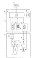
以下においては、ディスク・ドライブの一例であるハードディスク・ドライブ(HDD)を例として、本発明の実施形態を説明する本実施形態の特徴点の理解を容易とするため、最初に、HDDの全体構成の概略を説明する。図1は、本実施の形態に係るHDD1の全体構成を模式的に示すブロック図である。図1に示すように、HDD1は、密閉されたエンクロージャ10内に、メディア(記録媒体)の一例である磁気ディスク11、ヘッドの一例であるヘッド・スライダ12、アーム電子回路(AE:Arm Electronics)13、スピンドル・モータ(SPM)14、ボイス・コイル・モータ(VCM)15、そしてアクチュエータ16を備えている。
In the following, the hard disk drive (HDD), which is an example of a disk drive, will be taken as an example to describe the embodiments of the present invention. The outline of will be described. FIG. 1 is a block diagram schematically showing the overall configuration of the HDD 1 according to the present embodiment. As shown in FIG. 1, an HDD 1 includes a hermetically sealed
HDD1は、さらに、エンクロージャ10の外側に固定された回路基板20を備えている。回路基板20上には、リード・ライト・チャネル(R/Wチャネル)21、モータ・ドライバ・ユニット22、ハードディスク・コントローラ(HDC)とMPUの集積回路(以下、HDC/MPU)23及びRAM24などの各ICを備えている。さらに、回路基板20には、HDDの加速度を検知する加速度検知部25が実装されている。尚、各回路構成は一つのICに集積すること、あるいは、複数のICに分けて実装することができる。また、加速度検知部25はエンクロージャ10内に実装することができる。外部ホスト51からのユーザ・データは、HDC/MPU23によって受信され、R/Wチャネル21、AE13を介して、ヘッド・スライダ12によって磁気ディスク11に書き込まれる。また、磁気ディスク11に記憶されているユーザ・データはヘッド・スライダ12によって読み出され、そのユーザ・データは、AE13、R/Wチャネル21を介して、HDC/MPU23から外部ホスト51に出力される。
The HDD 1 further includes a
磁気ディスク11は、SPM14に固定されている。SPM14は所定の速度で磁気ディスク11を回転する。HDC/MPU23からの制御データに従って、モータ・ドライバ・ユニット22がSPM14を駆動する。本例の磁気ディスク11は、データを記録する記録面を両面に備え、各記録面に対応するヘッド・スライダ12が設けられている。各ヘッド・スライダ12は、磁気ディスク上を浮上するスライダと、スライダに固定され磁気信号と電気信号との間の変換を行うヘッド素子部とを備えている。本形態のヘッド・スライダ12は、加熱によってヘッド素子部を突出させ、その磁気ディスク11との間のクリアランス(浮上高)を調整するTFC(Thermal Fly height Control)のためのヒータを備えている。ヘッド・スライダ12の構造については、後に図2を参照して詳述する。
The
各ヘッド・スライダ12はアクチュエータ16の先端部に固定されている。アクチュエータ16はVCM15に連結され、回動軸を中心に回動することによって、ヘッドヘッド・スライダ12を回転する磁気ディスク11上においてその半径方向に移動する。モータ・ドライバ・ユニット22は、HDC/MPU23からの制御データ(DACOUTと呼ぶ)に従ってVCM15を駆動する。なお、磁気ディスク11は、1枚以上あればよく、記録面は磁気ディスク11の片面あるいは両面に形成することができる。
Each
AE13は、複数のヘッド素子部12の中から磁気ディスク11へのアクセスを行う1つのヘッド素子部12を選択し、選択されたヘッド素子部12により再生される再生信号を一定のゲインで増幅(プリアンプ)し、R/Wチャネル21に送る。また、R/Wチャネル21からの記録信号を選択されたヘッド素子部12に送る。AE13は、さらに、ヒータへ電流を供給し、その電流量(電力量)を調節する調節回路として機能する。
The
R/Wチャネル21は、リード処理において、AE13から供給されたリード信号を一定の振幅となるように増幅し、取得したリード信号からデータを抽出し、デコード処理を行う。読み出されるデータは、ユーザ・データとサーボ・データを含む。デコード処理されたリード・ユーザ・データは、HDC/MPU23に供給される。また、R/Wチャネル21は、ライト処理を、HDC/MPU23からの制御信号に従って実行する。ライト処理において、R/Wチャネル21はHDC/MPU23から供給されたライト・データをコード変調し、更にコード変調されたライト・データをライト信号に変換してAE13に供給する。
In the read process, the R /
HDC/MPU23において、MPUはRAM24にロードされたマイクロ・コードに従って動作する。HDD1の起動に伴い、RAM24には、MPU上で動作するマイクロ・コードの他、制御及びデータ処理に必要とされるデータが磁気ディスク11あるいはROM(不図示)からロードされる。HDC/MPU23は、リード/ライト処理制御、コマンド実行順序の管理、サーボ信号を使用したヘッド素子部12のポジショニング制御(サーボ制御)、インターフェース制御、ディフェクト管理などのデータ処理に関する必要な処理の他、HDD1の全体制御を実行する。特に、本形態のHDC/MPU23は、加速度検知部25が検知した加速度に基づいたTFCを実行する。この点については後述する。
In the HDC /
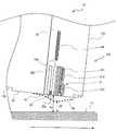
上述にように、本形態のHDD1はTFCが実装され、ヘッド素子部と磁気ディスク11との間のクリアランスを調整する。次に、本形態におけるTFCヘッド・スライダ12構成について説明を行う。図2は、ヘッド・スライダ12の空気流出端面(トレーリング側端面)121近傍におけるその一部構成を示す断面図である。磁気ディスク11は、図2の左から右に向かって回転する。ヘッド・スライダ12は、ヘッド素子部122とヘッド素子部122を支持するスライダ123とを備えている。なお、本形態のTFCは水平磁気記録及び垂直磁気記録のHDDに適用することができる。
As described above, the HDD 1 of the present embodiment is mounted with a TFC and adjusts the clearance between the head element unit and the
ヘッド素子部122は、磁気ディスク11との間で磁気データを読み書きする。ヘッド素子部122は、リード素子32とそのトレーリング側のライト素子31とを備えている。ライト素子31は、ライト・コイル311を流れる電流で磁極312間に磁界を発生し、磁気データを磁気ディスク11に記録するインダクティブ素子である。リード素子32は磁気抵抗型の素子であって、磁気異方性を有する磁気抵抗素子32aを備え、磁気ディスク11からの磁界によって変化するその抵抗値によって磁気ディスク11に記録されている磁気データを読み出す。
The
ヘッド素子部122は、スライダ123を構成するアルチック基板に、メッキ、スパッタ、研磨などの薄膜形成プロセスを用いて形成される。磁気抵抗素子32aは、磁気シールド33a、bによって挟まれており、ライト・コイル311は絶縁膜313で囲まれている。また、ヘッド素子部122はライト素子31とリード素子32の周囲にアルミナなどの保護膜34を備え、ヘッド素子部122全体はその保護膜34で保護されている。
The
ライト素子31およびリード素子32の近傍には、薄膜で形成された抵抗体によるヒータ124が薄膜プロセスを用いて形成されている。本例において、ヒータ124は、ヘッド素子部122の反磁気ディスク11側に位置している。例えば、薄膜抵抗体として、パーマロイを蛇行させ、間隙はアルミナで埋めてヒータ124を形成することができる。
In the vicinity of the
AE13がヒータ124に電流を流すと、ヒータ124の熱によってヘッド素子部122の近傍が突出変形する。非加熱時において、ヘッド・スライダ12のABS面は、S1で示される形状であり、ヘッド素子部122と磁気ディスクとの間の距離であるクリアランスは、C1で示されている。ヒータ124加熱時における突出形状S2を、図2に破線で示す。ヘッド素子部122が磁気ディスク11に近づき、このときのクリアランスC2は、クリアランスC1よりも小さい。なお、図2は概念図であり、寸法関係は正確ではない。例えば、突出面形状S2はナノメートル・オーダ(数ナノメートル)の突出量である。
When the
上述のように、本形態のHDD1はその加速度を検知し、検知した加速度に基づいてヒータ124のON/OFF制御を行ことによって、ヘッド素子部122と磁気ディスク11との衝突の発生を抑制する。好ましい態様として、図3に示すように、加速度検知部25は、無重力センサ251を備えている。無重力センサ251は重力方向における加速度を検知し、HDD1の落下を検知する。停止状態において、重力方向には1Gの加速度が存在する。重力方向において検知する加速度が基準値以下となると、無重力センサ251が落下を検知する。HDD1の落下を検知したことに応答してヒータ124をOFFすることで、衝突前に予めヘッド素子部122の突出量を減少させ、ヘッド素子部122と磁気ディスク11との衝突を防止する。
As described above, the HDD 1 of the present embodiment detects the acceleration, and controls the ON / OFF of the
例えば、無重力センサ251はX、Y、Z方向の3軸における加速度を検知し、3軸全ての方向で加速度が基準レベル以下となると落下状態であることを示す信号を出力する。センサのタイプとしては、例えば、ピエゾ抵抗型、静電容量型、磁気センサ型などが知られている。本形態の無重力センサ251は、これらのいずれのタイプのセンサを使用することもできる。
For example, the zero-
無重力センサ251が落下を検知すると、HDC/MPU23は、ヒータ124への電流供給を停止し、ヒータ124をOFFする。HDD1の落下後には大きな衝撃が加えられる蓋然性が高い。衝撃が加わる前にヒータ124をOFFしてヘッド素子部122突出量を小さくし、磁気ディスク11とヘッド素子部122との間のクリアランスを増加することでこれらの衝突を防止する。無重力センサ251が落下を検知してから衝撃が加えられるまでには相応の時間が経過するため、衝撃前に予めヘッド素子部122の突出量を小さくしておくことができる。
When the
さらに、HDC/MPU23は、アクチュエータ16(ヘッド素子部122)の残留振動を検知し、その残留振動が収まった後にヒータ122をONする。HDD1に衝撃が加わると、アクチュエータ16が大きく振動した後、特に共振周波数において大きな残留振動が起こる。残留振動が基準レベル以下になった後にヒータ124をONとすることで、残留振動によってヘッド素子部122と磁気ディスク11との衝突の可能性を低減する。
Further, the HDC /
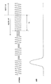
ヘッド素子部122(アクチュエータ16)の残留振動は、その読み出し信号の振幅に基づいて決定することができる。図4は、HDD1に加えられた衝撃と、ヘッド素子部122が磁気ディスク11から読み出した信号振幅との関係を模式的に示している。AE13の出力も、同様の変化を示す。
The residual vibration of the head element unit 122 (actuator 16) can be determined based on the amplitude of the read signal. FIG. 4 schematically shows the relationship between the impact applied to the HDD 1 and the signal amplitude read from the
衝撃があると、信号振幅が大きく変化する。ヘッド素子部122が磁気ディスク11から離れると振幅が減少し、近づくと増加する。衝撃があった後、残留振動のために、読み出し信号は振幅の増減を繰り返す。残留振動が収束すると、正常の信号振幅が続く。従って、残留振動有無の判定については、例えば、信号振幅が基準時間T0の間に基準以上の変化を示さない場合に、残留振動が収束したと判定することができる。
When there is an impact, the signal amplitude changes greatly. The amplitude decreases as the
各構成要素の処理について具体的に説明する。例えば、リード/ライト処理において、ホスト51からのコマンドに従って、HDC/MPU23は、アクチュエータ16を制御してヘッド素子部122をターゲット・セクタにむけて移動する。MPU232は、予め定められたタイミングにおいて、電流を供給してヒータ124をONする。その後、無重力センサ251がHDD1の落下を検知すると、MPU232はヒータ122をOFFするようにAE13に指示する。AE13は、MPU232からの指示に従って、ヒータ124への電力供給を停止する。
The processing of each component will be specifically described. For example, in the read / write process, the HDC /
その後、落下が停止すると、HDC/MPU23はサーボ制御によってヘッド素子部122のポジショニングを行う。このとき、MPU232は、R/Wチャネル21からサーボ信号の可変ゲイン・アンプ(VGA)のゲイン値(VGAゲイン)を取得する。R/Wチャネル21は、AE13からの信号についてオート・ゲイン・コントロール(AGC)行い、AE13からの信号を一定の振幅に増幅するように可変ゲイン・アンプ回路を備えている。
Thereafter, when the dropping stops, the HDC /
MPU232は、VGAゲインを使用して、ヘッド素子部122の残留振動を検出する。VGAゲインはAE13からの信号振幅と反比例の関係にあるので、図4に示した信号振幅と逆の増減変化を示す。MPU232は、例えば、基準時間T0の間、VGAゲインの変動もしくは最大値が基準レベル以下である場合に、残留振動が基準レベル以下に収束したと判定する。残留振動収束は、ヒータ124をONにする条件の一つとして使用され、他の条件が満たされたタイミングで、MPU232はヒータ124に電力を供給するONするようにAE13に指示する。
The
なお、R/Wチャネル21は、VGAゲインを格納するレジスタを備えており、そのレジスタにアクセスすることで、MPU232は衝撃後のVGAゲインを取得する。また、AE13がヒータ124のON/OFFもしくは電力(電流)値を格納するレジスタを備えており、MPU232はそのレジスタにアクセスしてヒータ124の制御を行う。
The R /
また、制御が複雑になるが、残留振動の検出には、サーボ信号の信号振幅の他に、ユーザ・データの信号振幅を使用することもできる。HDC/MPU23はサーボ制御と共に、R/Wチャネル21のユーザ・データの読み出しを制御する。サーボ信号のVGAゲインに加え、ユーザ・データのVGAゲインを取得して残留振動の判定に使用する。なお、上述の例おいては、MPU232は信号振幅に対応するVGAゲインを使用して残留振動の判定を行うが、AE13からの信号振幅の変化から直接に残留振動を判定することもできる。これらの点は、以下の他の態様において同様である。
Further, although the control is complicated, the signal amplitude of the user data can be used in addition to the signal amplitude of the servo signal for detecting the residual vibration. The HDC /
次に、加速度検出部25が、無重力センサ251に代えてショック・センサ252を備えている例について、図5を参照して説明する。ショック・センサ252は、1軸もしくは複数軸における加速度を検知し、その加速度つまり衝撃の大きさを示す信号を出力する。センサのタイプとしては、無重力センサ251と同様に、ピエゾ抵抗型、静電容量型、磁気センサ型のいずれのタイプを使用することもできる。
Next, an example in which the
本例のHDD1において、ショック・センサ252の衝撃検知に基づいて、HDC231がヒータ124をOFFする。図4を参照して説明したように、衝撃が加えられてからアクチュエータ16(ヘッド素子部122)が大きく変移するまでに、わずかながらインターバルが存在する。従って、その間にヒータ124をOFFしてヘッド素子部122の突出量を減少させることで、ヘッド素子部122と磁気ディスク11との衝突の可能性を低減する。
In the HDD 1 of this example, the
通常、ヒータ124の加熱に対するヘッド素子部122の突出・収縮の応答時間は、数msである。一方、HDD1に衝撃があってからヘッド素子部122が変移するまでの時間は衝撃に態様によって異なり、短いものは数msとなる。従って、ショック・センサ252が衝撃を検知してから即座にヒータ124をOFFすることが必要とされる。本例においては、ハードウェア・ロジックであるHDC231が、ショック・センサ252の検知に応答してヒータ124をOFFする。これによって、遅滞なくヒータ124をOFFする。
Usually, the response time of the protrusion / contraction of the
具体的には、リード/ライト処理などのためにヒータ124がONされている状態において、ショック・センサ252が基準以上の衝撃を検知すると、HDC231がそれに応答して、AE13にヒータ124をOFFするように指示する。その後、アクチュエータ16の残留振動が収束した後に、ヒータ124を再びONする。残留振動の検出方法は、上述の例と同様の構成とすることができるので、説明を省略する。
Specifically, when the
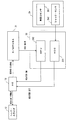
続いて、図6のブロック図に示すように、加速度検出部25が、無重力センサ251とショック・センサ252の双方を備えている例について説明する。これら二つのセンサを備えることによって、落下による衝撃に対して確実にヒータ124のON/OFF制御を行うことができると同時に、落下を伴わない衝撃に対してもヒータ124のON/OFF制御行うことができる。
Next, an example in which the
なお、本例においては加速度検出部25が二つのセンサ要素を備えるが、一つのセンサ要素がこれら二つの状態を検知できる構成としてもよい。また、本例においては、無重力センサ251及びショック・センサ252の双方の検知信号がHDC231に出力されるが、無重力センサ251の検知信号をMPU232が受け、それに従ってヒータ制御してもよい。
In addition, in this example, although the
図6のブロック図及び図7のフローチャートを参照しながら、本例のヒータ制御について説明する。リード/ライト処理など、磁気ディスク11へのアクセスが開始されると、MPU232はヒータ124をONする(S11)。つまり、MPU232は、AE13のレジスタにヒータONのコマンドをセットし、AE13がそれに従ってヒータ124に電力を供給する。
The heater control of this example will be described with reference to the block diagram of FIG. 6 and the flowchart of FIG. When access to the
その後、無重力センサ251がHDD1の落下を検知すると(S12におけるYES)、それを示す信号がHDC231に入力される。HDC231は、落下の検知に応答して、ヒータ124をOFFする(S14)。つまり、HDC231は、AE13のレジスタにヒータOFFのコマンドをセットし、AE13がそれに従ってヒータ124への電力供給を停止する。
Thereafter, when the
ヒータ124をOFFした後、HDD1はヘッド素子部122の残留振動を測定し、それが基準レベル以下に収束すると(S15)、ヒータ124がONされる(S16)。つまり、MPU232は、R/Wチャネル21におけるサーボ信号のVGAゲインをモニタし、その変化が基準レベル以下に収束するのを待ってヒータ124をONする。その後、エラー・リカバリ処理(ERP)などの所定の処理が行われる。
After the
ショック・センサ252が衝撃を検知すると(S13におけるYES)、それを示す信号がHDC232に入力される。HDC231は、落下の検知と同様に、基準レベル以上の衝撃の検知に応答して、ヒータ124をOFFする(S14)。その後の処理は上述の通りである。HDD1の落下及び衝撃が検知されない場合(S12及びS13におけるNO)、HDD1は通常の処理及びそれに伴うTFCを続行し、処理が完了する。
When
以上、本発明について好ましい実施形態を例として説明したが、本発明が上記の実施形態に限定されるものではない。当業者であれば、上記の実施形態の各要素を、本発明の範囲において容易に変更、追加、変換することが可能である。例えば、リード素子あるいはライト素子のみを備えるヘッド・スライダを実装するHDDに、本発明のTFCを適用することも可能である。また、同様のTFCを行う他のタイプのディスク・ドライブに適用することもできる。 As mentioned above, although preferable embodiment was described as an example about this invention, this invention is not limited to said embodiment. A person skilled in the art can easily change, add, and convert each element of the above-described embodiment within the scope of the present invention. For example, the TFC of the present invention can be applied to an HDD on which a head slider provided with only a read element or a write element is mounted. It can also be applied to other types of disk drives that perform similar TFC.
1 ハードディスク・ドライブ、10 エンクロージャ、11 磁気ディスク
12 ヘッド・スライダ、14 スピンドル・モータ、15 ボイス・コイル・モータ
16 アクチュエータ、17 ランプ、20 回路基板
21 リード・ライト・チャネル、22 モータ・ドライバ・ユニット
23 ハードディスク・コントローラ/MPU、24 RAM、25 加速度検知部
31 ライト素子、32 リード素子、32a 磁気抵抗素子、
33a、b シールド、34 保護膜、51 ホスト、
121 トレーリング側端面、122 ヘッド素子部、123 スライダ
124 ヒータ、251 無重力センサ、252 ショック・センサ
311 ライト・コイル、312 磁極、313 絶縁膜
DESCRIPTION OF SYMBOLS 1 Hard disk drive, 10 Enclosure, 11
33a, b shield, 34 protective film, 51 host,
121 Trailing side end face, 122 Head element part, 123
Claims (14)
前記スライダに配置されたヘッド素子部と、
前記スライダに配置され、前記ヘッド素子部を熱膨張によって突出させて前記記録ディスクとの間のクリアランスを調整するヒータと、
前記スライダを保持し移動するアクチュエータと、
加速度検知部と、
前記加速度検知部が検知した加速度に基づいて前記ヒータを制御するコントローラと、
を備えるディスク・ドライブ。 A slider that floats on a rotating recording disk;
A head element portion disposed on the slider;
A heater which is disposed on the slider and adjusts a clearance between the recording disk by projecting the head element portion by thermal expansion;
An actuator for holding and moving the slider;
An acceleration detector;
A controller for controlling the heater based on the acceleration detected by the acceleration detector;
A disk drive with
前記コントローラは、前記信号振幅を表すデータとして前記可変ゲイン・アンプのゲイン値を使用する、請求項6に記載のディスク・ドライブ。 A variable gain amplifier that amplifies the signal read by the head element unit;
The disk drive according to claim 6, wherein the controller uses a gain value of the variable gain amplifier as data representing the signal amplitude.
前記記録ディスクに前記ヘッド素子部がアクセスするために前記ヒータをONし、
前記ディスク・ドライブの落下及び/もしくは前記ディスク・ドライブへの衝撃を検知し、
前記ディスク・ドライブの落下もしくは基準レベル以上の衝撃を検知した場合に、前記ヒータをOFFする方法。 A slider that floats on a rotating recording disk, a head element section disposed on the slider, and a heater that is disposed on the slider and adjusts the clearance between the recording disk by projecting the head element section by thermal expansion. A control method in a disk drive comprising:
The heater is turned on for the head element unit to access the recording disk,
Detecting the fall of the disk drive and / or impact to the disk drive;
A method in which the heater is turned off when a drop of the disk drive or an impact exceeding a reference level is detected.
前記ディスク・ドライブの落下及び基準レベル以上の衝撃の少なくとも一方を検知した場合に前記ヒータをOFFする、請求項9に記載の方法。 Detecting the fall of the disk drive and the impact on the disk drive;
The method according to claim 9, wherein the heater is turned off when at least one of a fall of the disk drive and an impact exceeding a reference level is detected.
前記検出された残留振動が基準以下であることを条件として前記ヒータをONする、
請求項9に記載の方法。 After turning off the heater, the residual vibration of the head element portion is detected,
The heater is turned on on condition that the detected residual vibration is below a reference,
The method of claim 9.
前記スライダに配置されたヘッド素子部と、
前記スライダに配置され、前記ヘッド素子部を熱膨張によって突出させて前記記録ディスクとの間のクリアランスを調整するヒータと、
前記スライダを保持し移動するアクチュエータと、
前記ディスク・ドライブの落下及び/もしくは前記ディスク・ドライブへの衝撃を検知する検知部と、
前記ディスク・ドライブの落下もしくは基準レベル以上の衝撃を検知した場合に、前記ヒータをOFFするコントローラと、
を備えるディスク・ドライブ。 A slider that floats on a rotating recording disk;
A head element portion disposed on the slider;
A heater which is disposed on the slider and adjusts a clearance between the recording disk by projecting the head element portion by thermal expansion;
An actuator for holding and moving the slider;
A detection unit for detecting a fall of the disk drive and / or an impact on the disk drive;
A controller that turns off the heater when the disk drive is dropped or an impact exceeding a reference level is detected;
A disk drive with
Priority Applications (3)
| Application Number | Priority Date | Filing Date | Title |
|---|---|---|---|
| JP2006000254A JP2007184023A (en) | 2006-01-04 | 2006-01-04 | Disk drive and its control method |
| US11/645,251 US7616397B2 (en) | 2006-01-04 | 2006-12-21 | Disk drive and disk drive control method |
| CN2007100022513A CN101000788B (en) | 2006-01-04 | 2007-01-04 | Disk drive and disk drive control method |
Applications Claiming Priority (1)
| Application Number | Priority Date | Filing Date | Title |
|---|---|---|---|
| JP2006000254A JP2007184023A (en) | 2006-01-04 | 2006-01-04 | Disk drive and its control method |
Publications (2)
| Publication Number | Publication Date |
|---|---|
| JP2007184023A true JP2007184023A (en) | 2007-07-19 |
| JP2007184023A5 JP2007184023A5 (en) | 2009-02-05 |
Family
ID=38339973
Family Applications (1)
| Application Number | Title | Priority Date | Filing Date |
|---|---|---|---|
| JP2006000254A Pending JP2007184023A (en) | 2006-01-04 | 2006-01-04 | Disk drive and its control method |
Country Status (3)
| Country | Link |
|---|---|
| US (1) | US7616397B2 (en) |
| JP (1) | JP2007184023A (en) |
| CN (1) | CN101000788B (en) |
Cited By (1)
| Publication number | Priority date | Publication date | Assignee | Title |
|---|---|---|---|---|
| JP2007299517A (en) * | 2006-05-02 | 2007-11-15 | Samsung Electronics Co Ltd | Hard disk drive, fod voltage control method of hard disk drive, and recording medium with computer program for executing the method recorded thereon |
Families Citing this family (15)
| Publication number | Priority date | Publication date | Assignee | Title |
|---|---|---|---|---|
| KR100761841B1 (en) * | 2006-04-04 | 2007-09-28 | 삼성전자주식회사 | Apparatus and method for controlling a flying height of magnetic head in retry mode and disk drive using the same |
| KR100884002B1 (en) * | 2007-01-24 | 2009-02-17 | 삼성전자주식회사 | Head slider, hard disk drive with the same, and method for controlling a flying height of the head slider |
| JP2008186563A (en) * | 2007-01-31 | 2008-08-14 | Toshiba Corp | Disk storage and spacing control method |
| FR2912748B1 (en) * | 2007-02-16 | 2009-11-13 | Centre Nat Rech Scient | ALKYL H-PHOSPHONATES OF N, N'-DIALKYLIMIDAZOULIUMS, QUATERNARY AMMONIUMS AND USES THEREOF |
| JP2010123231A (en) * | 2008-11-21 | 2010-06-03 | Hitachi Global Storage Technologies Netherlands Bv | Disk drive and method for controlling clearance |
| US8199431B2 (en) * | 2010-04-08 | 2012-06-12 | Tdk Corporation | Magnetic head including sensor |
| US9773514B2 (en) * | 2011-02-25 | 2017-09-26 | Headway Technologies, Inc. | Magnetic head for perpendicular magnetic recording that includes a sensor for detecting contact with a recording medium |
| AU2012275265B2 (en) | 2011-06-29 | 2017-05-04 | Covidien Lp | Dissolution of oxidized cellulose |
| US8810953B2 (en) | 2011-12-02 | 2014-08-19 | HGST Netherlands B.V. | Error recovery based on applying current/voltage to a heating element of a magnetic head |
| US9271937B2 (en) | 2012-05-31 | 2016-03-01 | Covidien Lp | Oxidized cellulose microspheres |
| US9499636B2 (en) | 2012-06-28 | 2016-11-22 | Covidien Lp | Dissolution of oxidized cellulose and particle preparation by cross-linking with multivalent cations |
| US10413566B2 (en) | 2013-03-15 | 2019-09-17 | Covidien Lp | Thixotropic oxidized cellulose solutions and medical applications thereof |
| US9472224B2 (en) | 2013-12-05 | 2016-10-18 | Seagate Technology Llc | Electrically removable heater for a thermally actuatable thermal asperity sensor |
| US9558774B1 (en) * | 2015-09-25 | 2017-01-31 | Seagate Technology Llc | Recording head with electrically removable component |
| JP2023012315A (en) | 2021-07-13 | 2023-01-25 | 株式会社東芝 | magnetic disk device |
Citations (6)
| Publication number | Priority date | Publication date | Assignee | Title |
|---|---|---|---|---|
| JPH0887731A (en) * | 1994-09-14 | 1996-04-02 | Toshiba Corp | Magnetic recording and reproducing device |
| JPH09259556A (en) * | 1996-03-19 | 1997-10-03 | Toshiba Corp | Magnetic recording/reproducing apparatus |
| JP2005114402A (en) * | 2003-10-03 | 2005-04-28 | Sony Corp | Method and device for detecting falling-off |
| JP2005243105A (en) * | 2004-02-25 | 2005-09-08 | Hitachi Global Storage Technologies Netherlands Bv | Data storage device and control method therefor |
| JP2005322279A (en) * | 2004-05-06 | 2005-11-17 | Tdk Corp | Thin-film magnetic head equipped with heater, head gimbal assembly equipped with the same, and magnetic disk device equipped with the head gimbal assembly |
| JP2005346840A (en) * | 2004-06-03 | 2005-12-15 | Sony Corp | Fall detector, hard disk device and fall detection method |
Family Cites Families (14)
| Publication number | Priority date | Publication date | Assignee | Title |
|---|---|---|---|---|
| US4040103A (en) * | 1976-02-05 | 1977-08-02 | Sperry Rand Corporation | Shock force compensating system |
| JPH0520635A (en) | 1991-07-11 | 1993-01-29 | Fujitsu Ltd | Magnetic head and magnetic disk device |
| US6359746B1 (en) * | 1994-09-14 | 2002-03-19 | Kabushiki Kaisha Toshiba | Magnetic disk drive |
| US6046877A (en) * | 1995-02-16 | 2000-04-04 | Mobile Storage Technology, Inc. | Protection apparatus and method for hard disk drive unit of a portable computer |
| US5777815A (en) | 1996-06-13 | 1998-07-07 | International Business Machines Corporation | Disk drive with shock detection based on thermoresistive signal from magnetoresistive head |
| US5991113A (en) * | 1997-04-07 | 1999-11-23 | Seagate Technology, Inc. | Slider with temperature responsive transducer positioning |
| US6282038B1 (en) * | 1999-02-19 | 2001-08-28 | International Business Machines Corporation | Variable gain amplifier with temperature compensation for use in a disk drive system |
| JP3706015B2 (en) * | 2000-11-06 | 2005-10-12 | 株式会社日立グローバルストレージテクノロジーズ | Magnetic disk drive and control method thereof |
| US6683737B2 (en) * | 2001-07-19 | 2004-01-27 | Hitachi Global Storage Technologies Netherlands B.V. | Method and apparatus for predictive failure analysis technique for head crashes in hard drives using position error signal |
| JP2003272335A (en) * | 2002-03-13 | 2003-09-26 | Toshiba Corp | Magnetic disk device |
| JP4076434B2 (en) * | 2002-12-12 | 2008-04-16 | 株式会社日立グローバルストレージテクノロジーズ | Magnetic head and head gimbal assembly |
| JP3626954B2 (en) * | 2003-03-12 | 2005-03-09 | Tdk株式会社 | Thin-film magnetic head manufacturing method, thin-film magnetic head, head gimbal assembly, and hard disk device |
| JP2005004909A (en) | 2003-06-13 | 2005-01-06 | Hitachi Global Storage Technologies Inc | Magnetic disk device and floating control method of magnetic head slider |
| US7372665B1 (en) * | 2005-01-18 | 2008-05-13 | Western Digital (Fremont), Llc | Magnetic recording head with resistive heating element located near the write coil |
-
2006
- 2006-01-04 JP JP2006000254A patent/JP2007184023A/en active Pending
- 2006-12-21 US US11/645,251 patent/US7616397B2/en not_active Expired - Fee Related
-
2007
- 2007-01-04 CN CN2007100022513A patent/CN101000788B/en not_active Expired - Fee Related
Patent Citations (6)
| Publication number | Priority date | Publication date | Assignee | Title |
|---|---|---|---|---|
| JPH0887731A (en) * | 1994-09-14 | 1996-04-02 | Toshiba Corp | Magnetic recording and reproducing device |
| JPH09259556A (en) * | 1996-03-19 | 1997-10-03 | Toshiba Corp | Magnetic recording/reproducing apparatus |
| JP2005114402A (en) * | 2003-10-03 | 2005-04-28 | Sony Corp | Method and device for detecting falling-off |
| JP2005243105A (en) * | 2004-02-25 | 2005-09-08 | Hitachi Global Storage Technologies Netherlands Bv | Data storage device and control method therefor |
| JP2005322279A (en) * | 2004-05-06 | 2005-11-17 | Tdk Corp | Thin-film magnetic head equipped with heater, head gimbal assembly equipped with the same, and magnetic disk device equipped with the head gimbal assembly |
| JP2005346840A (en) * | 2004-06-03 | 2005-12-15 | Sony Corp | Fall detector, hard disk device and fall detection method |
Cited By (1)
| Publication number | Priority date | Publication date | Assignee | Title |
|---|---|---|---|---|
| JP2007299517A (en) * | 2006-05-02 | 2007-11-15 | Samsung Electronics Co Ltd | Hard disk drive, fod voltage control method of hard disk drive, and recording medium with computer program for executing the method recorded thereon |
Also Published As
| Publication number | Publication date |
|---|---|
| CN101000788A (en) | 2007-07-18 |
| US20080019032A1 (en) | 2008-01-24 |
| CN101000788B (en) | 2011-05-25 |
| US7616397B2 (en) | 2009-11-10 |
Similar Documents
| Publication | Publication Date | Title |
|---|---|---|
| JP2007184023A (en) | Disk drive and its control method | |
| US8773801B2 (en) | Magnetic-recording head with first thermal fly-height control element and embedded contact sensor element configurable as second thermal fly-height control element | |
| US7426089B2 (en) | Disk drive with heater for slider and control method thereof | |
| US8125728B2 (en) | Disk drive, head-slider and method for controlling clearance of a read element and a write element in the disk drive | |
| US7969681B2 (en) | Disk drive and control method thereof | |
| JP2009157987A (en) | Method for adjusting recess depth of head slider and disk drive device | |
| WO2010091084A1 (en) | Variable spindle speed control for data storage devices | |
| US7583467B2 (en) | Hard disk drive apparatus, method to control flying on demand of hard disk drive apparatus using thermal asperity signal, and recording media for computer program thereof | |
| JP2007066488A (en) | Data storage device, and method of controlling same | |
| JP2008204602A (en) | Hard disk drive apparatus, method to control flying height of magnetic head of hard disk drive, and recording medium recording computer program therefor | |
| JP2007294007A (en) | Disk drive device and control method thereof | |
| JP2006073075A (en) | Magnetic disk device and its control method | |
| US7719783B2 (en) | Hard disk drive with mechanism for controlling protrusion of head | |
| US20080180833A1 (en) | Method and apparatus for spacing control in a disk drive | |
| JP2007250162A (en) | Media drive device and its control method | |
| JP2006085832A (en) | Control method of recording current and magnetic disk apparatus | |
| JP4743855B2 (en) | Data storage device and control method thereof | |
| JP2007234113A (en) | Disk device and control method of disk device | |
| US7570446B2 (en) | Disk drive with improved format efficiency and control method thereof | |
| US7426086B2 (en) | Off track write protection for data storage device | |
| GB2381937A (en) | Write method for a storage system including a dummy write operation | |
| JP2009134834A (en) | Disk drive device and clearance adjustment method thereof | |
| US9542959B2 (en) | Protecting information written to recording medium | |
| JP2004095010A (en) | Disk drive and control method based on its environment temperature | |
| JP2009070452A (en) | Disk drive device and control method thereof |
Legal Events
| Date | Code | Title | Description |
|---|---|---|---|
| A521 | Written amendment |
Free format text: JAPANESE INTERMEDIATE CODE: A523 Effective date: 20081211 |
|
| A621 | Written request for application examination |
Free format text: JAPANESE INTERMEDIATE CODE: A621 Effective date: 20081211 |
|
| RD04 | Notification of resignation of power of attorney |
Free format text: JAPANESE INTERMEDIATE CODE: A7424 Effective date: 20100510 |
|
| A977 | Report on retrieval |
Free format text: JAPANESE INTERMEDIATE CODE: A971007 Effective date: 20110221 |
|
| A131 | Notification of reasons for refusal |
Free format text: JAPANESE INTERMEDIATE CODE: A131 Effective date: 20110301 |
|
| A02 | Decision of refusal |
Free format text: JAPANESE INTERMEDIATE CODE: A02 Effective date: 20111213 |