JP2007145055A - Automobile door hinge device - Google Patents
Automobile door hinge device Download PDFInfo
- Publication number
- JP2007145055A JP2007145055A JP2005338500A JP2005338500A JP2007145055A JP 2007145055 A JP2007145055 A JP 2007145055A JP 2005338500 A JP2005338500 A JP 2005338500A JP 2005338500 A JP2005338500 A JP 2005338500A JP 2007145055 A JP2007145055 A JP 2007145055A
- Authority
- JP
- Japan
- Prior art keywords
- door
- check
- check spring
- door hinge
- cylinder
- Prior art date
- Legal status (The legal status is an assumption and is not a legal conclusion. Google has not performed a legal analysis and makes no representation as to the accuracy of the status listed.)
- Pending
Links
- 230000002093 peripheral effect Effects 0.000 claims abstract description 17
- 238000010586 diagram Methods 0.000 description 7
- 230000004048 modification Effects 0.000 description 6
- 238000012986 modification Methods 0.000 description 6
- 230000008602 contraction Effects 0.000 description 3
- 238000005452 bending Methods 0.000 description 2
- 230000008878 coupling Effects 0.000 description 2
- 238000010168 coupling process Methods 0.000 description 2
- 238000005859 coupling reaction Methods 0.000 description 2
- 230000000149 penetrating effect Effects 0.000 description 2
- 239000000428 dust Substances 0.000 description 1
- 230000000694 effects Effects 0.000 description 1
- 230000001105 regulatory effect Effects 0.000 description 1
Images


Classifications
-
- E—FIXED CONSTRUCTIONS
- E05—LOCKS; KEYS; WINDOW OR DOOR FITTINGS; SAFES
- E05D—HINGES OR SUSPENSION DEVICES FOR DOORS, WINDOWS OR WINGS
- E05D11/00—Additional features or accessories of hinges
- E05D11/08—Friction devices between relatively-movable hinge parts
- E05D11/082—Friction devices between relatively-movable hinge parts with substantially radial friction, e.g. cylindrical friction surfaces
- E05D11/084—Friction devices between relatively-movable hinge parts with substantially radial friction, e.g. cylindrical friction surfaces the friction depending on direction of rotation or opening angle of the hinge
-
- E—FIXED CONSTRUCTIONS
- E05—LOCKS; KEYS; WINDOW OR DOOR FITTINGS; SAFES
- E05Y—INDEXING SCHEME ASSOCIATED WITH SUBCLASSES E05D AND E05F, RELATING TO CONSTRUCTION ELEMENTS, ELECTRIC CONTROL, POWER SUPPLY, POWER SIGNAL OR TRANSMISSION, USER INTERFACES, MOUNTING OR COUPLING, DETAILS, ACCESSORIES, AUXILIARY OPERATIONS NOT OTHERWISE PROVIDED FOR, APPLICATION THEREOF
- E05Y2900/00—Application of doors, windows, wings or fittings thereof
- E05Y2900/50—Application of doors, windows, wings or fittings thereof for vehicles
- E05Y2900/53—Type of wing
- E05Y2900/531—Doors
Landscapes
- Engineering & Computer Science (AREA)
- Mechanical Engineering (AREA)
- Hinge Accessories (AREA)
- Closing And Opening Devices For Wings, And Checks For Wings (AREA)
Abstract
Description
本発明は,ボディ及びドアの一方に固着される第1ブラケット,それらの他方に固着される第2ブラケット,及びこれら両ブラケットを相対回動可能に連結するヒンジピンを備える,自動車のドアヒンジ装置に関し,特にドアのチェック位置を問わない,つまりドアをどのような開度位置でも保持し得るドアヒンジ装置に関する。 The present invention relates to a door hinge device for an automobile, comprising a first bracket fixed to one of a body and a door, a second bracket fixed to the other of the body, and a hinge pin that connects both the brackets so as to be relatively rotatable. In particular, the present invention relates to a door hinge device that can hold the door at any opening position regardless of the door check position.
従来の自動車では,一般的に,ボディのドアを連結するドアヒンジの他に,ドアを所定の開度位置に保持するためのドアチェッカが設けられる。そのドアチェッカは,特許文献1に開示されるように,ドアに固着されるケースと,ボディに軸支されてケースを移動可能に貫通するチェックプレートと,ケースに保持されてチェックプレートに向かって進退し得るシューホルダと,このシューホルダに保持されて,ケース及びチェックプレートの相対移動に伴ないチェックプレート上を摺動するシューと,このシューをチェックプレートに圧接すべくケース内でシューホルダをチェックプレート側に弾発するチェックばねとを備え,チェックプレートには,シューが係合するデテントノッチを形成し,このデテントノッチとシューとの係合力によりドアを規定の開度に停止,保持するようにしたものが多い。
上記従来のドアチェッカでは,ドアを保持する開度が節度的に規定されているから,規定開度以外では,ドアを停止,保持することはできない。またそのドアチェッカは,ドアヒンジと並んでボディ及びドア間に取り付けられるので,全体として部品点数が多く,組立工数も多くなり,コストの低減に限界があり,また外観上も好ましくない。 In the conventional door checker described above, since the opening degree for holding the door is moderately specified, the door cannot be stopped and held at other than the specified opening degree. Further, since the door checker is mounted between the body and the door along with the door hinge, the number of parts as a whole is increased, the number of assembling steps is increased, the cost reduction is limited, and the appearance is not preferable.
本発明は,かゝる事情に鑑みてなされたもので,ドアヒンジが,ドアを,どのような開度でも保持し得る無段のドアチェック機能を発揮し得るようにした,自動車のドアヒンジ装置を提供することを目的とする。 SUMMARY OF THE INVENTION The present invention has been made in view of such circumstances. A door hinge device for an automobile in which a door hinge can exhibit a stepless door check function capable of holding the door at any opening degree. The purpose is to provide.
上記目的を達成するために,本発明は,ボディ及びドアの一方に固着される第1ブラケット,それらの他方に固着される第2ブラケット,及びこれら両ブラケットを相対回動可能に連結するヒンジピンを備える,自動車のドアヒンジ装置において,第1ブラケットに一体的に結合されてヒンジピンの外周に回転可能に嵌合する内側筒体と,第2ブラケットに一体的に結合されて内側筒体を囲繞する外側筒体と,内側筒体及び外側筒体間に配設されて内側筒体の外周面又は外側筒体の内周面にそれ自体の弾発力で圧接するチェックばねと,内側筒体及び外側筒体の一方に設けられてチェックばねの一端の第1係合部に対向配置され,内側筒体及び外側筒体の一方の相対回転時に該第1係合部を,チェックばねの前記圧接を解除する方向に変位させる第1制御部と,同じく内側筒体及び外側筒体の一方に設けられてチェックばねの他端の第2係合部に対向配置され,内側筒体及び外側筒体の他方の相対回転時に該第2係合部を,チェックばねの前記圧接を解除する方向に変位させる第2制御部とを備えることを第1の特徴とする。 In order to achieve the above object, the present invention includes a first bracket fixed to one of the body and the door, a second bracket fixed to the other of them, and a hinge pin for connecting both the brackets so as to be relatively rotatable. In an automobile door hinge device, an inner cylinder integrally coupled to the first bracket and rotatably fitted on the outer periphery of the hinge pin, and an outer integrally coupled to the second bracket and surrounding the inner cylinder A check spring disposed between the inner cylinder and the outer cylinder and pressed against the outer peripheral surface of the inner cylinder or the inner peripheral surface of the outer cylinder by its own elastic force, the inner cylinder and the outer cylinder One of the cylinders is disposed opposite to the first engagement part at one end of the check spring. When the inner cylinder and the outer cylinder are relatively rotated, the first engagement part is connected to the pressure contact of the check spring. Displaced in the release direction The first control unit is provided on one of the inner cylinder and the outer cylinder, and is disposed opposite to the second engagement part at the other end of the check spring. When the other of the inner cylinder and the outer cylinder rotates relative to each other, A first feature is that the second engagement portion includes a second control portion that displaces the second engagement portion in a direction to release the pressure contact of the check spring.
また本発明は,第1の特徴に加えて,チェックばねを,これが外側筒体の内周面に圧接するように構成すると共に,第1及び第2制御部を内側筒体に設けたことを第2の特徴とする。 According to the present invention, in addition to the first feature, the check spring is configured so that it is pressed against the inner peripheral surface of the outer cylinder, and the first and second control portions are provided on the inner cylinder. The second feature.
さらに本発明は,第1の特徴に加えて,チェックばねを,これが内側筒体の外周面に圧接するように構成すると共に,第1及び第2制御部を外側筒体に設けたことを第3の特徴とする。 Furthermore, in addition to the first feature, the present invention is configured such that the check spring is configured so as to be pressed against the outer peripheral surface of the inner cylinder, and the first and second control units are provided on the outer cylinder. Three features.
さらにまた本発明は,第1〜第3の特徴の何れかに加えて,チェックばねをコイルばねで構成したことを第4の特徴とする。 Furthermore, in addition to any of the first to third features, the present invention has a fourth feature in that the check spring is constituted by a coil spring.
本発明の第1の特徴によれば,雌ブラケット及び雄ブラケットをヒンジピンにより連結してなるドアヒンジに,内側筒体,外側筒体及びチェックばねを組み込むことにより,ドアヒンジに,ドアチェック機能を付与するようにしたので,全体として部品点数が少なく,したがって組立工数も少なく,コストの低減及び外観の向上に寄与し得るドアヒンジ装置を提供することができる。しかも,そのドアチェック機能は,ドアを,どのような開度でも保持し得るので,常にドアの妄動を防ぐことができる。 According to the first feature of the present invention, a door check function is provided to the door hinge by incorporating the inner cylinder body, the outer cylinder body and the check spring into the door hinge formed by connecting the female bracket and the male bracket with the hinge pin. As a result, it is possible to provide a door hinge device that has a small number of parts as a whole and therefore has a small number of assembly steps, and that can contribute to cost reduction and appearance improvement. In addition, the door check function can keep the door at any opening, so that it can always prevent the door from moving away.
本発明の第2の特徴によれば,チェックばねの拡張弾発力により,チェックばね及び外側筒体間に大なる摩擦力を発生させ,これによりドアを任意の開度位置に保持することができる。 According to the second feature of the present invention, a large frictional force is generated between the check spring and the outer cylindrical body by the expanded elastic force of the check spring, whereby the door can be held at an arbitrary opening position. it can.
本発明の第3の特徴によれば,チェックばねの収縮弾発力により,チェックばね及び内側筒体間に大なる摩擦力を発生させ,これによりドアを任意の開度位置に保持することができる。 According to the third feature of the present invention, a large frictional force is generated between the check spring and the inner cylindrical body by the contraction elastic force of the check spring, and thereby the door can be held at an arbitrary opening position. it can.
本発明の第4の特徴によれば,チェックばねをコイルばねで構成することで,チェックばねの全周面を外側筒体の内周面又は内側筒体の外周面に確実に圧接させることができ,ドアに対する保持力を常に安定させることができる。 According to the fourth feature of the present invention, the check spring is constituted by a coil spring, so that the entire peripheral surface of the check spring can be reliably pressed against the inner peripheral surface of the outer cylinder or the outer peripheral surface of the inner cylinder. And the holding force against the door can always be stabilized.
本発明の実施の形態を,添付図面に示す本発明の好適な実施例に基づいて以下に説明する。 Embodiments of the present invention will be described below on the basis of preferred embodiments of the present invention shown in the accompanying drawings.
本発明の実施の形態を,添付図面に示す本発明の実施例に基づいて以下に説明する。 DESCRIPTION OF THE PREFERRED EMBODIMENTS Embodiments of the present invention will be described below based on examples of the present invention shown in the accompanying drawings.
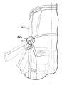
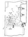
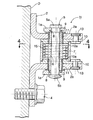
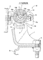
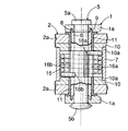
図1は本発明の第1実施例に係るドアヒンジ装置を備える自動車の要部斜視図,図2は図1の2部拡大図,図3は図2の3−3線拡大断面図,図4は図3の4−4線断面図(ドアの全閉状態を示す。),図5は図4の5−5線断面図,図6は上記ドアヒンジ装置の分解斜視図,図7はドアの中間開度保持状態を示す,図4との対応図,図8はドアの全開状態を示す,図4との対応図,図9は本発明の第2実施例を示す,図4との対応図(ドアの全閉状態を示す。),図10はドアの中間開度保持状態を示す,図9との対応図,図11はドアの全開状態を示す,図9との対応図,図12は前記第1実施例中のチェックばねの変形例を示す斜視図,図13は前記第2実施例中のチェックばねの変形例を示す斜視図である。
1 is a perspective view of an essential part of an automobile equipped with a door hinge device according to a first embodiment of the present invention, FIG. 2 is an enlarged view of
先ず,図1〜図8に示す本発明の第1実施例の説明より始める。 First, the description starts with the description of the first embodiment of the present invention shown in FIGS.
図1及び図2において,自動車のボディBに,その乗降口を開閉すべくドアDが上下一対のドアヒンジH(図には,その内の一つを示す。)を介して回動可能に取付けられる。各ドアヒンジHは,ボディBに複数のボルト3,3で固着される雌ブラケット1と,ドアDに複数のボルト4,4で固着される雄ブラケット2と,これら両ブラケット1,2を相対回動可能に連結すべく鉛直方向に配置されるヒンジピン5とで構成される。
1 and 2, a door D is rotatably attached to a body B of an automobile via a pair of upper and lower door hinges H (one of them is shown in the figure) so as to open and close its entrance. It is done. Each door hinge H includes a female bracket 1 fixed to the body B with a plurality of
図2〜図6に示すように,上記一対のドアヒンジHの内の一方又は両方に,更に次のような構成が付与される。 As shown in FIGS. 2 to 6, one or both of the pair of door hinges H is further provided with the following configuration.
雌ブラケット1の上下一対の雌アーム部1a,1aの内側に,雄ブラケット2の上下一対の雄アーム部2a,2aがそれぞれ隣接して配置され,これらを上下に貫通するように前記ヒンジピン5が配置される。このヒンジピン5の外周には,雌アーム部1a,1aを貫通する内側筒体6が相対回転可能に嵌合され,この内側筒体6の両端部は雌アーム部1a,1aに,それらの対向面にそれぞれ設けられる各複数の凸部8及び凹部9の係合により一体的に結合され,その結合状態は,ヒンジピン5の頭部5a及びかしめ端部5bにより保持される。
A pair of upper and lower
一対の雄アーム部2a,2aの内側面には,内側筒体6に貫通される一対の蓋板10,10がそれぞれリベット13,13により固着され,互いに固着された各雄アーム部2a及び蓋板10には,内側筒体6を回転自在に支承する共通の軸受ブッシュ11が装着される。
A pair of
一対の蓋板10,10の相対向面には,内側筒体6と同心の円形の連結ボス10a,10aがそれぞれ一体に形成されており,これら連結ボス10a,10aの外周面に外側筒体7の両端部が圧入されて固着される。したがって,この外側筒体7は,内側筒体6を同心上で囲繞するように配置されることになり,この外側筒体7内にチェックばね15が収容される。このチェックばね15は,コイルばねよりなるもので,その自由状態では,外径が外側筒体7の内径より大きく設定されており,これを半径方向に収縮させて外側筒体7に挿入し,収縮力を解除することにより,チェックばね15は,それ自体の拡張弾発力で外側筒体7の内周面に圧接するように配設される。
図4〜図6に示すように,チェックばね15の両端には,該ばねの素線端末を半径方向内方に屈曲してなる第1及び第2係合部15a,15bが形成されており,これら第1及び第2係合部15a,15bの,チェックばね15の周方向に沿う内側面にそれぞれ微小間隙を存して対向する第1及び第2制御部16a,16bが内側筒体6の外周に形成される。
As shown in FIGS. 4 to 6, first and second
図4及び図8に示すように,雌ブラケット1及び雄ブラケット2には,互いに当接可能に対向する固定ストッパ部19及び可動ストッパ部18がそれぞれ形成され,これらが互いに当接することでドアDの全開位置が規制されるようになっている。
As shown in FIGS. 4 and 8, the female bracket 1 and the
次に,この第1実施例の作用について説明する。 Next, the operation of the first embodiment will be described.
内側筒体6は,ボディBに固着される雌ブラケット1に一体的に結合され,外側筒体7は,ドアDに固着される雄ブラケット2に一体的に結合されるので,内側筒体6及び外側筒体7は,ドアDの開閉に伴ない相対的に回転することになる。
Since the
一方,外側筒体7内に配置されるチェックばね15は,通常,それ自体の拡張弾発力により外側筒体7の内周面に圧接していているため,外側筒体7及びチェックばね15間には,それらの相対回転に抵抗する大なる摩擦力が発生している。また内側筒体6の第1及び第2制御部16a,16bは,チェックばね15の回転を阻止するように,その第1及び第2係合部15a,15bに対向する。
On the other hand, the
したがって,例えば図4,図7及び図8に示すように,ドアDがどのような開度位置にあろうとも,無負荷状態に置かれるときは,チェックばね15及び外側筒体7間の大なる摩擦力により,ドアDをその任意の停止位置に保持することができる。
Therefore, as shown in FIGS. 4, 7 and 8, for example, when the door D is placed in an unloaded state regardless of the opening position, a large space between the
図7に示すように,例えば任意の中間開度位置に保持されるドアDに所定値以上の開き操作力Oを加えれば,内側筒体6の第1制御部16aがチェックばね15の第1係合部15aを相対的に押動してチェックばね15を絞り込み,これによりチェックばね15を半径方向に収縮させ,チェックばね15と外側筒体7との間の摩擦力を減少させるため,外側筒体7及びチェックばね15間に滑りを生じさせながら,ドアDをスムーズに開くことができる。
As shown in FIG. 7, for example, if an opening operation force O of a predetermined value or more is applied to the door D held at an arbitrary intermediate opening position, the
またドアDに所定値以上の閉じ操作力Cを加えれば,今度は内側筒体6の第2制御部16bがチェックばね15の第2係合部15bを押動して,同じくチェックばね15を絞り込み,これによりチェックばね15を半径方向に収縮させ,チェックばね15と外側筒体7との間の摩擦力を減少させるため,外側筒体7及びチェックばね15間に滑りを生じさせながら,ドアDをスムーズに閉じることができる。
Further, if a closing operation force C of a predetermined value or more is applied to the door D, the
上記のようにしてドアDを開き方向又は閉じ方向に回動して,任意の開度位置でドアDに対する開き操作力O又は閉じ操作力Cを解除すれば,ドアDは再び無負荷状態となり,前述のようにチェックばね15及び外側筒体7間に発生する大なる摩擦力により,そのドアDを,その任意の停止位置に保持することができる。
If the door D is rotated in the opening direction or the closing direction as described above and the opening operation force O or the closing operation force C for the door D is released at an arbitrary opening position, the door D is again in a no-load state. As described above, the door D can be held at the arbitrary stop position by the large frictional force generated between the
上記のように,雌ブラケット1及び雄ブラケット2をヒンジピン5により連結してなるドアヒンジHに,内側筒体6,外側筒体7及びチェックばね15を組み込むことにより,ドアヒンジHに,ドアチェック機能を付与するようにしたので,全体として部品点数が少なく,したがって組立工数も少なく,コストの低減及び外観の向上に寄与し得るドアチェック装置を提供することができ,しかも,そのドアチェック機能は,ドアを,どのような開度でも保持し得るので,常にドアの妄動を防ぐことができる。
As described above, by incorporating the
またチェックばね15を収容する外側筒体7の両端の開放面は,一対の蓋板10,10により閉塞されるので,外観を一層良好にすることができると共に,外側筒体7内への塵埃等の侵入を防ぎ,チェックばね15及び外側筒体7間の摩擦力特性の安定化を図ることができる。
In addition, since the open surfaces at both ends of the
さらにチェックばね15はコイルばねで構成されるので,その全周面を外側筒体7の内周面に確実に圧接させることができ,ドアDに対する保持力を常に安定させることができる。
Further, since the
次に,図9〜図11に示す本発明の第2実施例について説明する。 Next, a second embodiment of the present invention shown in FIGS. 9 to 11 will be described.
この第2実施例では,コイルばねよりなるチェックばね115を,その自由状態では,内径が内側筒体16の外径より小さくなるに構成し,これを半径方向に拡張させて内側筒体16の外周に嵌めた後,拡張力を解除することにより,チェックばね115は,それ自体の収縮弾発力で内側筒体16の外周面に圧接するように配設される。
In the second embodiment, the
チェックばね115の両端には,該ばねの素線端末を半径方向外方に屈曲してなる第1及び第2係合部115a,115bが形成され,これら第1及び第2係合部115a,115bの,チェックばね115の周方向に沿う内側面にそれぞれ微小間隙を存して対向する第1及び第2制御部116a,116bが外側筒体17の外周に形成される。その他の構成は前実施例と同様であるので,図9〜図11中,前実施例と対応する部分には同一の参照符号を付して,重複する説明を省略する。
At both ends of the
而して,外側筒体17内に配置されるチェックばね115は,通常,それ自体の収縮弾発力により内側筒体16の内周面に圧接していているため,内側筒体16及びチェックばね115間には,それらの相対回転に抵抗する大なる摩擦力が発生している。また外側筒体17の第1及び第2制御部116a,116bは,チェックばね115の回転を阻止するように,その第1及び第2係合部115a,115bに対向する。
Thus, the
したがって,例えば図9〜図11に示すように,ドアDがどのような開度位置にあろうとも,無負荷状態に置かれるときは,チェックばね115及び内側筒体16間の大なる摩擦力により,ドアDをその任意の停止位置に保持することができる。
Therefore, for example, as shown in FIGS. 9 to 11, when the door D is placed in an unloaded state regardless of the opening position, a large frictional force between the
図10に示すように,例えば任意の中間開度位置に保持されるドアDに所定値以上の開き操作力Oを加えれば,外側筒体17の第1制御部116aがチェックばね115の第1係合部115aを押動してチェックばね115を半径方向に拡張させ,チェックばね115と内側筒体16との間の摩擦力を減少させるため,内側筒体16及びチェックばね115間に滑りを生じさせながら,ドアDをスムーズに開くことができる。
As shown in FIG. 10, for example, if an opening operation force O equal to or greater than a predetermined value is applied to the door D held at an arbitrary intermediate opening position, the
またドアDに所定値以上の閉じ操作力Cを加えれば,今度は外側筒体17の第2制御部116bがチェックばね115の第2係合部115bを押動して,同じくチェックばね115を半径方向に拡張させ,チェックばね115と内側筒体16との間の摩擦力を減少させるため,内側筒体16及びチェックばね115間に滑りを生じさせながら,ドアDをスムーズに閉じることができる。
If a closing operation force C greater than or equal to a predetermined value is applied to the door D, the
上記のようにしてドアDを開き方向又は閉じ方向に回動して,任意の開度位置でドアDに対する開き操作力O又は閉じ操作力Cを解除すれば,ドアDは再び無負荷状態となり,前述のようにチェックばね115及び外側筒体17間に発生する大なる摩擦力により,そのドアDを,その任意の停止位置に保持することができる。 そして,この第2実施例によっても前記第1実施例と同様の効果を達成することができる。
If the door D is rotated in the opening direction or the closing direction as described above and the opening operation force O or the closing operation force C for the door D is released at an arbitrary opening position, the door D is again in a no-load state. As described above, the door D can be held at the arbitrary stop position by the large frictional force generated between the
図12は,前記第1実施例中のチェックばね15の変形例を示すもので,この場合のチェックばね215は,板ばねを優弧状に曲げると共に,その両端部を半径方向内方に屈曲させて第1及び第2係合部215a,215bに形成したものであり,その外側筒体7及び内側筒体6への取り付け構造及び機能は,第1実施例と同様である。
FIG. 12 shows a modification of the
また図13は,前記第2実施例中のチェックばね115の変形例を示すもので,この場合のチェックばね315は,板ばねを優弧状に曲げると共に,その両端部を半径方向外方に屈曲させて第1及び第2係合部315a,315bに形成したものであり,その外側筒体17及び内側筒体16への取り付け構造及び機能は,第2実施例と同様である。
FIG. 13 shows a modification of the
本発明は,上記実施例に限定されるものではなく,その要旨を逸脱しない範囲で種々の設計変更が可能である。例えば,雌ブラケット1はドアDに,雄ブラケット2はボディBにそれぞれ固着することもできる。
The present invention is not limited to the above embodiments, and various design changes can be made without departing from the scope of the invention. For example, the female bracket 1 can be fixed to the door D, and the
B・・・・・ボディ
D・・・・・ドア
H・・・・・ドアヒンジ
1・・・・・第1ブラケット(雌ブラケット)
2・・・・・第2ブラケット(雄ブラケット)
5・・・・・ヒンジピン
6,16・・・内側筒体
7,17・・・外側筒体
15,115,215,315・・・チェックばね
15a,115a・・・第1係合部
15b,115b・・・第2係合部
16a,116a・・・第1制御部
16b,116b・・・第2制御部
B ... Body D ... Door H ... Door hinge 1 ... First bracket (female bracket)
2 ... 2nd bracket (male bracket)
5... Hinge pins 6, 16...
Claims (4)
第1ブラケット(1)に一体的に結合されてヒンジピン(5)の外周に回転可能に嵌合する内側筒体(6,16)と,第2ブラケット(2)に一体的に結合されて内側筒体(6,16)を囲繞する外側筒体(7,17)と,内側筒体(6,16)及び外側筒体(7,17)間に配設されて内側筒体(6,16)の外周面又は外側筒体(7,17)の内周面にそれ自体の弾発力で圧接するチェックばね(15,115,215,315)と,内側筒体(6,16)及び外側筒体(7,17)の一方に設けられてチェックばね(15,115,215,31216,316)の一端の第1係合部(15a,115a,215a,315a)に対向配置され,内側筒体(6,16)及び外側筒体(7,17)の一方の相対回転時に該第1係合部(15a,115a,215a,315a)を,チェックばね(15,115,215,315)の前記圧接を解除する方向に変位させる第1制御部(16a,116a)と,同じく内側筒体(6,16)及び外側筒体(7,17)の一方に設けられてチェックばね(15,115,215,315)の他端の第2係合部(15b,115b,215b,315b)に対向配置され,内側筒体(6,16)及び外側筒体(7,17)の他方の相対回転時に該第2係合部(15b,115b,215b,315b)を,チェックばね(15,115,215,315)の前記圧接を解除する方向に変位させる第2制御部(16b,116b)とを備えることを特徴とする,自動車のドアヒンジ装置。 The first bracket (1) fixed to one of the body (B) and the door (D), the second bracket (2) fixed to the other of them, and the two brackets (1, 2) can be rotated relative to each other. In a door hinge device of an automobile, comprising a hinge pin (5) connected to
An inner cylinder (6, 16) integrally coupled to the first bracket (1) and rotatably fitted to the outer periphery of the hinge pin (5), and an inner cylinder (6) integrally coupled to the second bracket (2) An outer cylinder (7, 17) surrounding the cylinder (6, 16) and an inner cylinder (6, 16) disposed between the inner cylinder (6, 16) and the outer cylinder (7, 17). ) Or the outer cylinder (7, 17), the inner spring (15, 115, 215, 315), the inner cylinder (6, 16) and the outer cylinder. It is provided on one side of the cylindrical body (7, 17) and is arranged opposite to the first engaging portion (15a, 115a, 215a, 315a) at one end of the check spring (15, 115, 215, 31216, 316), During the relative rotation of one of the body (6, 16) and the outer cylinder (7, 17), the first engaging portion (1 a, 115a, 215a, 315a) and a first control part (16a, 116a) for displacing the check springs (15, 115, 215, 315) in the direction to release the pressure contact, and the inner cylinders (6, 16). ) And the outer cylindrical body (7, 17) and disposed opposite to the second engaging portion (15b, 115b, 215b, 315b) at the other end of the check spring (15, 115, 215, 315), When the other of the inner cylinder (6, 16) and the outer cylinder (7, 17) is rotated relative to the other, the second engaging portion (15b, 115b, 215b, 315b) is connected to the check spring (15, 115, 215, 315). And a second control unit (16b, 116b) that displaces the pressure contact in a direction to release the pressure contact.
チェックばね(15,215)を,これが外側筒体(7)の内周面に圧接するように構成すると共に,第1及び第2制御部(16a,16b)を内側筒体(6,16)に設けたことを特徴とする,自動車のドアヒンジ装置。 The door hinge device for an automobile according to claim 1,
The check springs (15, 215) are configured so as to be in pressure contact with the inner peripheral surface of the outer cylinder (7), and the first and second control units (16a, 16b) are configured as the inner cylinders (6, 16). A door hinge device for an automobile characterized by being provided in
チェックばね(115,315)を,これが内側筒体(6,16)の外周面に圧接するように構成すると共に,第1及び第2制御部(116a,116b,)を外側筒体(7,17)に設けたことを特徴とする,自動車のドアヒンジ装置。 The door hinge device for an automobile according to claim 1,
The check springs (115, 315) are configured so as to be pressed against the outer peripheral surface of the inner cylinder (6, 16), and the first and second control units (116a, 116b,) are configured to be connected to the outer cylinder (7, 17) A door hinge device for an automobile characterized by being provided in 17).
チェックばね(15,115)をコイルばねで構成したことを特徴とする,自動車のドアヒンジ装置。
In the door hinge apparatus of the motor vehicle in any one of Claims 1-3,
A door hinge device for an automobile, wherein the check springs (15, 115) are coil springs.
Priority Applications (4)
| Application Number | Priority Date | Filing Date | Title |
|---|---|---|---|
| JP2005338500A JP2007145055A (en) | 2005-11-24 | 2005-11-24 | Automobile door hinge device |
| US11/602,468 US20070136993A1 (en) | 2005-11-24 | 2006-11-21 | Automobile door hinge device |
| CA002568819A CA2568819A1 (en) | 2005-11-24 | 2006-11-23 | Automobile door hinge device |
| CN200610146776.XA CN1970983A (en) | 2005-11-24 | 2006-11-24 | Automobile door hinge device |
Applications Claiming Priority (1)
| Application Number | Priority Date | Filing Date | Title |
|---|---|---|---|
| JP2005338500A JP2007145055A (en) | 2005-11-24 | 2005-11-24 | Automobile door hinge device |
Publications (2)
| Publication Number | Publication Date |
|---|---|
| JP2007145055A true JP2007145055A (en) | 2007-06-14 |
| JP2007145055A5 JP2007145055A5 (en) | 2008-12-04 |
Family
ID=38066760
Family Applications (1)
| Application Number | Title | Priority Date | Filing Date |
|---|---|---|---|
| JP2005338500A Pending JP2007145055A (en) | 2005-11-24 | 2005-11-24 | Automobile door hinge device |
Country Status (4)
| Country | Link |
|---|---|
| US (1) | US20070136993A1 (en) |
| JP (1) | JP2007145055A (en) |
| CN (1) | CN1970983A (en) |
| CA (1) | CA2568819A1 (en) |
Cited By (2)
| Publication number | Priority date | Publication date | Assignee | Title |
|---|---|---|---|---|
| JP2008144569A (en) * | 2006-11-17 | 2008-06-26 | Honda Motor Co Ltd | Door hinge with check function for vehicle |
| KR101936964B1 (en) | 2013-11-19 | 2019-01-09 | 현대자동차주식회사 | Door hinge apparatus having door checker |
Families Citing this family (6)
| Publication number | Priority date | Publication date | Assignee | Title |
|---|---|---|---|---|
| JP2008157012A (en) * | 2006-12-01 | 2008-07-10 | Riken Kaki Kogyo Kk | Vehicular door hinge device with checker |
| JP5090811B2 (en) * | 2007-07-20 | 2012-12-05 | 理研化機工業株式会社 | Door hinge device with checker for vehicle |
| EP2476566A4 (en) * | 2009-09-10 | 2014-01-29 | Toyota Auto Body Co Ltd | Hinge for vehicle door |
| US20160130850A1 (en) * | 2014-11-12 | 2016-05-12 | Duncan Bolt Co. | Tamper resitant hinge pin retention |
| US20180298647A1 (en) * | 2017-04-13 | 2018-10-18 | Ford Global Technologies, Llc | Supplemental active lock mechanism for center-opening door assembly |
| CN111379486A (en) * | 2018-12-28 | 2020-07-07 | 观致汽车有限公司 | Hinge with integrated infinite limiter |
Citations (4)
| Publication number | Priority date | Publication date | Assignee | Title |
|---|---|---|---|---|
| US244539A (en) * | 1881-07-19 | beown | ||
| JPH053561U (en) * | 1991-06-26 | 1993-01-19 | 日本発条株式会社 | Lock hinge |
| JPH0639526U (en) * | 1992-11-05 | 1994-05-27 | デルタ工業株式会社 | Car door checker |
| JP2000045614A (en) * | 1998-07-31 | 2000-02-15 | Sugatsune Ind Co Ltd | Free stop hinge |
Family Cites Families (6)
| Publication number | Priority date | Publication date | Assignee | Title |
|---|---|---|---|---|
| US571133A (en) * | 1896-11-10 | Spring-hinge | ||
| CA2277114C (en) * | 1999-07-07 | 2004-06-01 | Multimatic Inc. | Integrated door check hinge for automobiles |
| US7096536B2 (en) * | 2002-06-07 | 2006-08-29 | Illinois Tool Works Inc | Hinge apparatus with check mechanism |
| US6779234B1 (en) * | 2003-04-14 | 2004-08-24 | Shin Zu Shing Co., Ltd. | Elastic hinge for a notebook computer |
| US6938303B2 (en) * | 2003-10-22 | 2005-09-06 | Daimlerchrysler Corporation | Double pivot concealed hinge |
| US7076836B1 (en) * | 2004-06-28 | 2006-07-18 | Honda Motor Co., Ltd. | Integrated hinge and temporary door checker |
-
2005
- 2005-11-24 JP JP2005338500A patent/JP2007145055A/en active Pending
-
2006
- 2006-11-21 US US11/602,468 patent/US20070136993A1/en not_active Abandoned
- 2006-11-23 CA CA002568819A patent/CA2568819A1/en not_active Abandoned
- 2006-11-24 CN CN200610146776.XA patent/CN1970983A/en active Pending
Patent Citations (4)
| Publication number | Priority date | Publication date | Assignee | Title |
|---|---|---|---|---|
| US244539A (en) * | 1881-07-19 | beown | ||
| JPH053561U (en) * | 1991-06-26 | 1993-01-19 | 日本発条株式会社 | Lock hinge |
| JPH0639526U (en) * | 1992-11-05 | 1994-05-27 | デルタ工業株式会社 | Car door checker |
| JP2000045614A (en) * | 1998-07-31 | 2000-02-15 | Sugatsune Ind Co Ltd | Free stop hinge |
Cited By (4)
| Publication number | Priority date | Publication date | Assignee | Title |
|---|---|---|---|---|
| JP2008144569A (en) * | 2006-11-17 | 2008-06-26 | Honda Motor Co Ltd | Door hinge with check function for vehicle |
| JP4734283B2 (en) * | 2006-11-17 | 2011-07-27 | 本田技研工業株式会社 | Door hinge with vehicle check function |
| US8136204B2 (en) | 2006-11-17 | 2012-03-20 | Honda Motor Co., Ltd. | Door hinge for vehicle, having check function |
| KR101936964B1 (en) | 2013-11-19 | 2019-01-09 | 현대자동차주식회사 | Door hinge apparatus having door checker |
Also Published As
| Publication number | Publication date |
|---|---|
| CN1970983A (en) | 2007-05-30 |
| US20070136993A1 (en) | 2007-06-21 |
| CA2568819A1 (en) | 2007-05-24 |
Similar Documents
| Publication | Publication Date | Title |
|---|---|---|
| JP2007145055A (en) | Automobile door hinge device | |
| US8108969B2 (en) | Checker-equipped door hinge device for vehicle | |
| JP2007145055A5 (en) | ||
| US7506406B2 (en) | Door checker for automobile | |
| JP5307637B2 (en) | Hinge device | |
| JP4199230B2 (en) | Hinge structure of vehicle glove box | |
| US8347460B2 (en) | Checker-equipped door hinge device for vehicle | |
| JP4308254B2 (en) | Hinge with damper | |
| JP2009024429A5 (en) | ||
| JP2008157012A (en) | Vehicular door hinge device with checker | |
| JP2016216973A (en) | Resistance generating device | |
| JP2006290296A (en) | Door checker | |
| EP1411203B1 (en) | Clutch | |
| JP5507008B2 (en) | Hinge mechanism and in-vehicle display device | |
| JP6663390B2 (en) | Switchgear for trunk lid | |
| JP5215896B2 (en) | Anti-seismic hinge and door device using the same | |
| JP4701023B2 (en) | Hinge structure | |
| WO2010134211A1 (en) | Hinge apparatus | |
| JP2012181416A (en) | Opening/closing device of document pressure plate | |
| JP5215930B2 (en) | Hinge manufacturing method, anti-seismic hinge and door device using it | |
| JP2005054971A (en) | Hinge unit | |
| JP2004116275A (en) | Flange type pipe spring and hinge device using the same | |
| JP4394129B2 (en) | Door closing order adjuster | |
| JP2010151182A (en) | Hinge device | |
| JP3010223B2 (en) | Hinge device |
Legal Events
| Date | Code | Title | Description |
|---|---|---|---|
| A521 | Request for written amendment filed |
Free format text: JAPANESE INTERMEDIATE CODE: A523 Effective date: 20081022 |
|
| A621 | Written request for application examination |
Free format text: JAPANESE INTERMEDIATE CODE: A621 Effective date: 20081022 |
|
| A131 | Notification of reasons for refusal |
Free format text: JAPANESE INTERMEDIATE CODE: A131 Effective date: 20110119 |
|
| A977 | Report on retrieval |
Free format text: JAPANESE INTERMEDIATE CODE: A971007 Effective date: 20110120 |
|
| A02 | Decision of refusal |
Free format text: JAPANESE INTERMEDIATE CODE: A02 Effective date: 20110727 |