JP2007124657A - Cellular single frequency network, base station, mobile terminal, and transmission method in mobile network - Google Patents
Cellular single frequency network, base station, mobile terminal, and transmission method in mobile network Download PDFInfo
- Publication number
- JP2007124657A JP2007124657A JP2006290753A JP2006290753A JP2007124657A JP 2007124657 A JP2007124657 A JP 2007124657A JP 2006290753 A JP2006290753 A JP 2006290753A JP 2006290753 A JP2006290753 A JP 2006290753A JP 2007124657 A JP2007124657 A JP 2007124657A
- Authority
- JP
- Japan
- Prior art keywords
- pilot
- antenna
- frequency
- antennas
- power
- Prior art date
- Legal status (The legal status is an assumption and is not a legal conclusion. Google has not performed a legal analysis and makes no representation as to the accuracy of the status listed.)
- Withdrawn
Links
Images


Classifications
-
- H—ELECTRICITY
- H04—ELECTRIC COMMUNICATION TECHNIQUE
- H04B—TRANSMISSION
- H04B7/00—Radio transmission systems, i.e. using radiation field
- H04B7/14—Relay systems
- H04B7/15—Active relay systems
- H04B7/185—Space-based or airborne stations; Stations for satellite systems
- H04B7/18521—Systems of inter linked satellites, i.e. inter satellite service
-
- H—ELECTRICITY
- H04—ELECTRIC COMMUNICATION TECHNIQUE
- H04L—TRANSMISSION OF DIGITAL INFORMATION, e.g. TELEGRAPHIC COMMUNICATION
- H04L23/00—Apparatus or local circuits for systems other than those covered by groups H04L15/00 - H04L21/00
- H04L23/02—Apparatus or local circuits for systems other than those covered by groups H04L15/00 - H04L21/00 adapted for orthogonal signalling
-
- H—ELECTRICITY
- H04—ELECTRIC COMMUNICATION TECHNIQUE
- H04L—TRANSMISSION OF DIGITAL INFORMATION, e.g. TELEGRAPHIC COMMUNICATION
- H04L27/00—Modulated-carrier systems
- H04L27/26—Systems using multi-frequency codes
- H04L27/2601—Multicarrier modulation systems
- H04L27/2602—Signal structure
- H04L27/261—Details of reference signals
- H04L27/2613—Structure of the reference signals
-
- H—ELECTRICITY
- H04—ELECTRIC COMMUNICATION TECHNIQUE
- H04L—TRANSMISSION OF DIGITAL INFORMATION, e.g. TELEGRAPHIC COMMUNICATION
- H04L25/00—Baseband systems
- H04L25/02—Details ; arrangements for supplying electrical power along data transmission lines
- H04L25/0202—Channel estimation
- H04L25/0224—Channel estimation using sounding signals
- H04L25/0228—Channel estimation using sounding signals with direct estimation from sounding signals
-
- H—ELECTRICITY
- H04—ELECTRIC COMMUNICATION TECHNIQUE
- H04L—TRANSMISSION OF DIGITAL INFORMATION, e.g. TELEGRAPHIC COMMUNICATION
- H04L5/00—Arrangements affording multiple use of the transmission path
- H04L5/0001—Arrangements for dividing the transmission path
- H04L5/0014—Three-dimensional division
- H04L5/0023—Time-frequency-space
-
- H—ELECTRICITY
- H04—ELECTRIC COMMUNICATION TECHNIQUE
- H04L—TRANSMISSION OF DIGITAL INFORMATION, e.g. TELEGRAPHIC COMMUNICATION
- H04L5/00—Arrangements affording multiple use of the transmission path
- H04L5/003—Arrangements for allocating sub-channels of the transmission path
- H04L5/0048—Allocation of pilot signals, i.e. of signals known to the receiver
Landscapes
- Engineering & Computer Science (AREA)
- Computer Networks & Wireless Communication (AREA)
- Signal Processing (AREA)
- Physics & Mathematics (AREA)
- Astronomy & Astrophysics (AREA)
- Aviation & Aerospace Engineering (AREA)
- General Physics & Mathematics (AREA)
- Mobile Radio Communication Systems (AREA)
Abstract
Description
本発明は請求項1のプリアンブルに記載のセル式単一周波数ネットワーク、請求項17のプリアンブルに記載のモバイル端末、請求項18のプリアンブルに記載の基地局、および請求項19のプリアンブルに記載のモバイルネットワークでの伝送方法に関する。
The present invention relates to a cellular single frequency network according to the preamble of
直交周波数多重分割(OFDM)無線システムは、3GPP技術仕様化グループ(TSG)の無線アクセスネットワーク(RAN1)など、多くの場所で現在議論中である。こうした無線システムは、現在のW−CDMA(W−CDMA=広帯域符号分割多重アクセス)のような単一周波数のネットワークであるべきである。 Orthogonal frequency division multiplexing (OFDM) radio systems are currently under discussion in many places, such as the 3GPP Technical Specification Group (TSG) Radio Access Network (RAN1). Such a radio system should be a single frequency network such as current W-CDMA (W-CDMA = Wideband Code Division Multiple Access).
OFDMチャネル、すなわちOFDMの時間・周波数グリッドは、異なるユーザまたはモバイル端末の間で多重化されなければならない。一部のビーム形成が信号対干渉・ノイズ比(SINR)(signal to interference plus noise ratio)を引き上げるために使用されなければならないため、および優良なSINR値を有する一部の多重入出力(MIMO)伝送がデータ処理率を増加させるのに使用されることが可能なため、OFDMチャネルのうちの一部は適応可能な副搬送波割当または周波数スケジューリングに含まれなければならず、一部のものは特にセルの端部での干渉調整から利益を得ることが可能である。さらに、ビーム形成は一部のユーザまたはモバイル端末のためには、それらの速度が理由で、使用されることができないが、それらが配置されている方向から独立した、改良されたSINR値は必要とされる。 The OFDM channel, that is, the OFDM time and frequency grid, must be multiplexed between different users or mobile terminals. Some beamforming must be used to raise signal to interference plus noise ratio (SINR), and some Multiple Input / Output (MIMO) with good SINR values Since transmission can be used to increase the data processing rate, some of the OFDM channels must be included in adaptive subcarrier allocation or frequency scheduling, some of which are especially It is possible to benefit from interference adjustment at the edge of the cell. In addition, beamforming cannot be used for some users or mobile terminals because of their speed, but an improved SINR value is required, independent of the direction in which they are located. It is said.
したがって、セルに所属するすべてのモバイル端末が現在ある受信環境から独立して受信できなければならないということから、異なるモバイル端末への専用データの送信、および共通の制御チャネル送信が必要とされる。 Therefore, since all mobile terminals belonging to a cell must be able to receive independently from the current reception environment, transmission of dedicated data to different mobile terminals and transmission of a common control channel are required.
さらなる1つの目標は、アンテナパイロット情報を搬送する伝送時間間隔(TTI)の中で数個のOFDMシンボルか、または場合によっては1つのみのOFDMシンボルとともに機能することと、いわゆるマイクロスリープ方式を可能にすることである。 One further goal is to work with several OFDM symbols or possibly only one OFDM symbol in a transmission time interval (TTI) carrying antenna pilot information and to enable a so-called microsleep scheme Is to do.
本発明の目的は、チャネル多重化構造に構成されたパイロットを用いた、OFDMシステムでのビーム形成、MIMO伝送、周波数スケジューリングおよび干渉調整のための方法を提案することである。 An object of the present invention is to propose a method for beam forming, MIMO transmission, frequency scheduling and interference adjustment in an OFDM system using pilots configured in a channel multiplexing structure.
この目的は、請求項1の教示による方法、請求項17の教示による基地局、請求項18の教示によるモバイル端末、および請求項19の教示によるモバイルネットワークによって達成される。
This object is achieved by a method according to the teaching of
本発明の主な着想は、パイロット拡散系列長(pilot spreading sequence length)が帯域幅に適合し、パイロット拡散系列長が、セルの端部か、またはそれを越えて行われるモバイル端末によるチャネル推定が可能になるために、および必要であれば逆拡散パイロットを使用してチャネル推定を実行するために十分に長くなるように、チャネル多重化のために、周波数ブロックの周波数帯域幅を備えた隣接するOFDM副搬送波の周波数ブロックを使用することである。 The main idea of the present invention is that channel estimation by a mobile terminal is performed where the pilot spreading sequence length is adapted to the bandwidth and the pilot spreading sequence length is at or beyond the edge of the cell. Adjacent with frequency bandwidth of frequency blocks for channel multiplexing to be possible and long enough to perform channel estimation using despread pilot if necessary Using frequency blocks of OFDM subcarriers.
本発明のさらなる展開は、従属請求項および以下の説明から集められることが可能である。 Further developments of the invention can be gathered from the dependent claims and the following description.
以下で、本発明は添付の図面を参照することによって、さらに説明される。 In the following, the present invention will be further described by reference to the accompanying drawings.
本発明によるモバイルネットワークは、モバイル端末と基地局とを含む。 The mobile network according to the present invention includes a mobile terminal and a base station.
前記モバイル端末の各々は、1つまたは複数の前記基地局に接続され、基地局は基地局コントローラを経由して、順次中核ネットワークに接続される。 Each of the mobile terminals is connected to one or more of the base stations, and the base stations are sequentially connected to the core network via a base station controller.
モバイル端末は、例えばOFDMネットワークなどの単一周波数ネットワークでの送信および受信のためのモバイル端末の機能を含み、すなわちこれらは基地局によってモバイルネットワークに接続されることが可能である。 A mobile terminal includes the mobile terminal's capabilities for transmission and reception in a single frequency network, eg, an OFDM network, ie, they can be connected to the mobile network by a base station.
さらに、本発明によるモバイル端末は、周波数ブロックの各々の周波数帯域幅に適合し、チャネル推定を可能にするために十分に長いパイロット拡散系列長を備えたパイロットを含むチャネルの多重化のために使用されるOFDM副搬送波に隣接する周波数ブロックを受信するための手段を含み、モバイル端末はチャネル推定を可能にするために十分に長いパイロット拡散系列長を備えた前記パイロットを使用して、チャネル推定を実行するための手段を含む。 Furthermore, the mobile terminal according to the present invention is used for multiplexing of channels including pilots with pilot spreading sequence lengths that are sufficiently long to accommodate the frequency bandwidth of each of the frequency blocks and to enable channel estimation. Means for receiving a frequency block adjacent to an OFDM subcarrier, wherein the mobile terminal uses the pilot with a sufficiently long pilot spreading sequence length to enable channel estimation, and performs channel estimation. Means for performing.
基地局はWLANまたはOFDMネットワークなどの単一周波数ネットワークの基地局の機能を含み、すなわちそれらはモバイルネットワークに接続される可能性をモバイル端末に提供する。 The base station includes the functions of a base station of a single frequency network such as a WLAN or OFDM network, i.e. they provide the mobile terminal with the possibility to be connected to the mobile network.
基地局は、モバイル端末の信号またはデータへ送信するか、またはモバイル端末の信号またはデータから受信するための少なくとも1つのアンテナを含む。 The base station includes at least one antenna for transmitting to or receiving from the mobile terminal signal or data.
さらに本発明による基地局は、パイロット拡散系列長が周波数ブロックの各々の周波数帯域幅に適合するようなチャネル多重化に使用される、隣接するOFDM副搬送波の周波数ブロックを選択するための手段を含み、基地局はチャネル推定を可能にするために十分に長いパイロット拡散系列長を選択するための手段を含む。 Furthermore, the base station according to the invention comprises means for selecting frequency blocks of adjacent OFDM subcarriers used for channel multiplexing such that the pilot spreading sequence length is adapted to the frequency bandwidth of each of the frequency blocks. The base station includes means for selecting a sufficiently long pilot spreading sequence length to enable channel estimation.
以下で、本発明による方法は実施例として、図1から7を参照して詳細に説明される。 In the following, the method according to the invention will be described in detail by way of example with reference to FIGS.
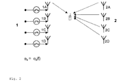
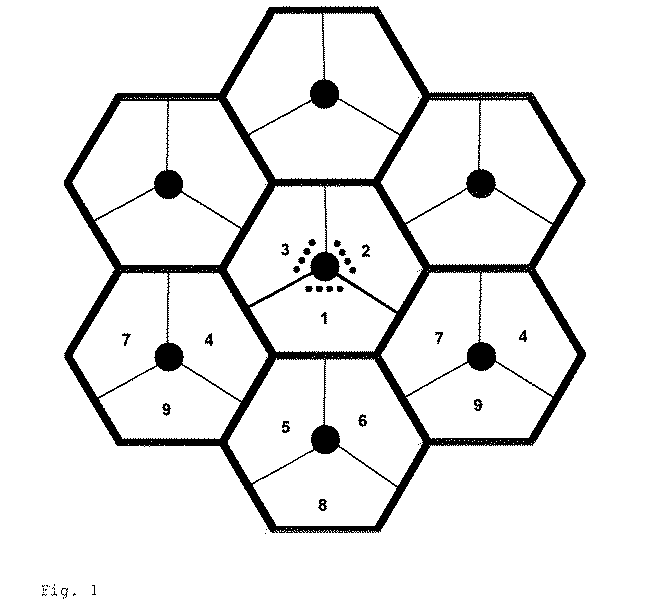
TDM方式のパイロットは例えば、時間枠の中の例えば7つのOFDMシンボルのうちの1つまたは複数のOFDMシンボルの中でパイロット副搬送波が配置されるところで使用されることが可能である。これらのパイロット副搬送波は、1つまたは複数のアンテナ伝送のために使用され、アンテナに特有のものとしてセットされる。セクタ当たり4つのアンテナのためのシナリオは、セクタ化されたセルが1、2および3と表示されるセクタを有するものとして、図1に例として示されている。セクタ1、2および3の各々で、4つのアンテナは点で表されているとする。隣接するセルもまた、例えばすべてがアンテナ特有のパイロットを送信することができる複数のアンテナを備えた、これらのセクタを有する。
A TDM pilot may be used, for example, where pilot subcarriers are arranged in one or more OFDM symbols of, for example, seven OFDM symbols in a time frame. These pilot subcarriers are used for one or more antenna transmissions and are set as antenna specific. A scenario for four antennas per sector is shown by way of example in FIG. 1 with the sectorized cells having sectors denoted 1, 2 and 3. Assume that in each of
図2はセクタ1からの4つのアンテナ1A、1B、1Cおよび1D、ならびにセクタ2からの4つのアンテナ2A、2B、2Cおよび2Dを示す。送信されるパイロットは、2つのセクタまたは2つのセルの間の干渉領域の中のモバイル端末のためにも、チャネル推定が可能となるように適合されなければならない。モバイル端末はセル1のアンテナ1Aからのアンテナに特有のパイロットを測定しなければならず、セル2からの4つのアンテナからの4倍の干渉に対処しなければならない。
FIG. 2 shows four
TDMパイロットの構成は図3に示される。ここで副搬送波周波数は時間に対して記入される。TTI間隔とも呼ばれるデータの時間枠の単位は、s個のOFDMシンボルから構成される。図3で、例えば0.5ミリ秒のTTI間隔は例として、0、1、・・・6と表示されるs=7のOFDMシンボルから構成される。各OFDMシンボルは、パイロットまたはデータが配置されることが可能な周波数軸に沿った、例えばM=72である、Mの有効な副搬送波を有する。パイロット情報を運搬するOFDMシンボルは、図3の中で1と表示されるOFDMシンボルである。パイロット情報を運搬するOFDMシンボルは通常パイロットのみを運搬するが、パイロットとデータとを運搬することもまた可能である。 The structure of the TDM pilot is shown in FIG. Here, the subcarrier frequency is entered with respect to time. The unit of data time frame, also called TTI interval, is composed of s OFDM symbols. In FIG. 3, for example, a TTI interval of 0.5 milliseconds is composed of s = 7 OFDM symbols denoted as 0, 1,. Each OFDM symbol has M valid subcarriers, eg, M = 72, along the frequency axis where pilot or data can be located. The OFDM symbol that carries pilot information is the OFDM symbol labeled 1 in FIG. OFDM symbols that carry pilot information usually carry only pilots, but it is also possible to carry pilots and data.
隣接するセルの間でのパイロット調整を必要としないために、パイロット副搬送波シンボルはデータ副搬送波シンボルとほぼ同じ電力を有するべきであり、パイロット拡散とセルに特有のスクランブル符号とを備えた構成が使用されるべきである。したがって各アンテナのために、図3に丸または四角で表示されているような、アンテナ特有の拡散系列が使用されるべきである。 In order not to require pilot adjustment between adjacent cells, the pilot subcarrier symbol should have approximately the same power as the data subcarrier symbol, and the configuration with pilot spreading and cell specific scrambling codes Should be used. Therefore, for each antenna, an antenna-specific spreading sequence, such as represented by a circle or square in FIG. 3, should be used.
さらに、時間が同期化されておらず、調整されることが不可能な隣接するセルへの、またはそうした隣接するセルからの影響をランダム化するために、例えばすべてのパイロットシンボルのための周波数軸に沿った、セルに特有のスクランブリングが使用されるべきである。このことは、起こりうるパイロット対パイロットの干渉を回避する。 In addition, the frequency axis for all pilot symbols, for example, to randomize the effects to or from neighboring cells that are not time synchronized and cannot be adjusted. Cell-specific scrambling along the line should be used. This avoids possible pilot-to-pilot interference.
パイロットの逆拡散からの利得によって、モバイル端末がセルの重複する領域にあり、信号対干渉比がSIR=−7、・・・−8dBとなる場合でさえもチャネル推定を可能にする、干渉よりもパイロット信号水準がずっと高くなることが達成される。このためには約6の逆拡散利得が必要である。 Gain from pilot despreading enables channel estimation even when mobile terminals are in overlapping areas of the cell and the signal-to-interference ratio is SIR = −7,. Even higher pilot signal levels are achieved. This requires a despread gain of about 6.
1つの基地局の隣接するセクタに属するアンテナは、少なくとも同期化されているとみなされることが可能である。したがって、アンテナに特有の直交拡散系列は1つのセルの中で使用される。次に、1つのセクタの1つのOFDMシンボルか、または隣接するセクタの2つ以上のアンテナパイロットは、チャネル転送関数が拡散系列長に沿ってほぼ一定していれば、受信機の中で直交であるとみなされることが可能である。このことによって、各伝送アンテナのためのすべてのチャネル転送関数の推定が可能になる。 Antennas belonging to adjacent sectors of one base station can be considered at least synchronized. Therefore, the orthogonal spreading sequence specific to the antenna is used in one cell. Next, one OFDM symbol in one sector, or two or more antenna pilots in adjacent sectors, are orthogonal in the receiver if the channel transfer function is approximately constant along the spreading sequence length. It can be considered to be. This allows estimation of all channel transfer functions for each transmit antenna.
各セクタにアンテナが2つの場合、例えば1つの隣接するセルアンテナのための四位相偏移変調のデータ振幅は
![]()
![]()
![]()
![]()
制御チャネルデータはパイロットとともに、または単一のOFDMシンボル上で適時に分配されるパイロット情報の隣のOFDMシンボルの中で伝送される。このような方法で、チャネル推定は共通の制御チャネルのシンボルに適用される場合、非常にうまく行われる。さらに、いわゆるマイクロスリープ方式では、モバイル端末は1つのOFDMシンボルでパイロット情報を受信して、次のOFDMシンボルで制御チャネルを復号することが可能であり、基地局によってアドレスされない場合には静止状態に入る、すなわち電力を節約するために信号処理のスイッチを切り、TTIの中のすべての他のOFDMの受信を省略することができる。 Control channel data is transmitted with the pilot or in the OFDM symbol next to the pilot information distributed in time on a single OFDM symbol. In this way, channel estimation is performed very well when applied to common control channel symbols. Furthermore, in the so-called microsleep method, the mobile terminal can receive pilot information with one OFDM symbol and decode the control channel with the next OFDM symbol, and is stationary when not addressed by the base station. In order to save power, the signal processing can be switched off and reception of all other OFDMs in the TTI can be omitted.
さらに、図2に示すようなアンテナウェイトまたは位相要素
![]()
![]()
本発明により、チャネルの多重化のために、パイロット拡散系列長が帯域幅に適合し、パイロット拡散系列長が、セルの端部か、またはそれを越えるモバイル端末によるチャネル推定が可能になるために十分に長くなるように、隣接するOFDM副搬送波の周波数ブロックはブロックの周波数帯域幅とともに使用され、必要であれば、逆拡散パイロットを使用するチャネル推定が実行される。 According to the present invention, for channel multiplexing, the pilot spreading sequence length is adapted to the bandwidth, and the pilot spreading sequence length can be estimated by the mobile terminal at or beyond the end of the cell. To be sufficiently long, adjacent OFDM subcarrier frequency blocks are used with the frequency bandwidth of the block, and if necessary, channel estimation using despread pilots is performed.
周波数ブロックは図3に示され、FB1、FB2、FB3等と表示される。 The frequency blocks are shown in FIG. 3 and are labeled FB1, FB2, FB3, etc.
本発明の実施形態で、前記周波数ブロックは、例えば周波数ブロック間に櫛状の形で挿入された、多様な周波数の周波数パターンとともに組み合わせられる。図4に示すように、これらは制御情報か、または例えばマルチメディアブロードキャスト(MBMS)情報のために使用されることが可能である。 In an embodiment of the present invention, the frequency blocks are combined with frequency patterns of various frequencies inserted, for example, in a comb shape between the frequency blocks. As shown in FIG. 4, these can be used for control information or for example, multimedia broadcast (MBMS) information.
本発明の実施形態で、1つまたは複数のOFDMシンボルの副搬送波は周波数ブロックの内部で共通の制御チャネルに割り当てられる。 In an embodiment of the present invention, the subcarriers of one or more OFDM symbols are assigned to a common control channel within the frequency block.
本発明の実施形態で、各ブロックのための周波数ブロックに特有のアンテナウェイトか、または各パターンのための周波数パターンに特有のアンテナウェイトが使用される。ブロックの内部でこれらのウェイトはさらに制御のために、および1つまたは複数のデータ部分のために異なっていてもよい。 In an embodiment of the present invention, the antenna weight specific to the frequency block for each block or the antenna weight specific to the frequency pattern for each pattern is used. Within a block, these weights may be different for further control and for one or more data portions.
本発明の実施形態で、前記周波数ブロックのデータ部分はビーム形成、MIMO伝送、周波数スケジューリングまたは干渉調整の目的で、異なるチャネル状態にある異なるユーザに割り当てられて、これらの割り当てられたブロックの内部で、アンテナ上の適切な分配によって、アンテナパイロットおよびアンテナウェイトの適切な構成によって、必要であれば、非常に遠距離に配置されたユーザのためでもあり、同時に専用データのためでもある制御データの全方向伝送、ビーム形成もしくはMIMO伝送、または周波数ブロックおよびユーザに依存する通常の伝送を形成し、前記周波数ブロック割当またはスケジューリングは、チャネル推定の測定値もしくはパイロット測定値もしくは干渉測定値もしくは特定のユーザの処理量の増大に関する測定に基づいて、またはMIMOもしくはビーム形成伝送のために算出された予測処理量に基づいて行われる。 In an embodiment of the present invention, the data portion of the frequency block is allocated to different users in different channel states for the purpose of beamforming, MIMO transmission, frequency scheduling or interference coordination, and within these allocated blocks. By appropriate distribution on the antennas, by appropriate configuration of the antenna pilots and antenna weights, if necessary, all of the control data, both for users located at very long distances and at the same time for dedicated data Form directional transmission, beamforming or MIMO transmission, or normal transmission depending on frequency block and user, said frequency block allocation or scheduling is a channel estimation measurement or pilot measurement or interference measurement or a specific user's For increased throughput Based on the measurements, or is performed based on the prediction processing amount calculated for MIMO or beamforming transmission.
本発明の実施形態では、各セクタまたはセルの中で周波数ブロックに配置された多様な周波数の特定の組合せは、セル1およびセル2の2つのセルのための時間・周波数グリッドの中の点で表された周波数ブロックとして示される、前記組合せの中のすべての周波数ブロックでの電力と使用の制限を課すために、例えば図5で示されるように選択される。次いで前記組合せは、モバイル端末が干渉調整から、すなわち制限されたセルの境界で前記周波数ブロックを使用することにより改善されたSIR率から利益を得ることができるように、セルまたはセクタ間で異なることが可能である。
In an embodiment of the present invention, the particular combination of various frequencies arranged in the frequency block within each sector or cell is a point in the time-frequency grid for two cells,
本発明の実施形態で、アンテナに特有のパイロットと、それらに応じて異なる電力を備えた複数のアンテナのための、引き起こされた干渉を制限するための同様のパイロットとが使用される。 In embodiments of the present invention, antenna specific pilots and similar pilots for limiting the induced interference for multiple antennas with different powers accordingly are used.
本発明の実施形態で、各周波数ブロックの制御情報部分は、電力が適切に高められたアンテナパイロットを備えた単一のアンテナを介してのみ伝送され、さらに制御情報の伝送のための異なるアンテナは、アンテナ間の電力の釣り合わせを達成するために周波数ブロックによって選択される。 In an embodiment of the present invention, the control information portion of each frequency block is transmitted only via a single antenna with an appropriately enhanced antenna pilot, and different antennas for transmission of control information are , Selected by the frequency block to achieve a power balance between the antennas.
本発明の実施形態で、アンテナが制御チャネルを伝送するアンテナパイロットの電力は高められ、別のパイロットはセット1と呼ばれるすべてのアンテナのうちの一部を介してビーム指示ウェイトとともに伝送され、データ部分はセット1のために、ビーム形成のために以前に選択された同様のビーム指示ウェイトを使用して、すべてのアンテナを介して伝送され、すべてのアンテナの一部(セット1)を介して伝送されるこの別のパイロットの電力は、特にビームの外部の干渉を軽減するために弱められる。
In an embodiment of the present invention, the power of the antenna pilot on which the antenna transmits the control channel is increased, and another pilot is transmitted with a beam indication weight via a portion of all the antennas called
本発明の実施形態で、1つの周波数ブロックは全方向伝送のために、1つのアンテナからのみ1つのパイロットとともに送信され、パイロットの電力は、例えばすべてのパイロットに利用可能な最大総電力を使い切るために高められる。 In an embodiment of the present invention, one frequency block is transmitted with only one pilot from one antenna for omnidirectional transmission, and the pilot power is used, for example, to use up the maximum total power available to all pilots. Enhanced.
本発明の1つの実施形態で、アンテナ特有のパイロットは周波数ブロックのパイロット部分で、例えば位相要素を伴わずに各アンテナから送信され、アンテナが制御チャネルを伝送するアンテナパイロットの電力は高められ、別のパイロットはすべてのパイロットのために利用可能な総パイロット電力を保存するために弱められ、各アンテナでは、MIMO伝送のためのアンテナ特有のデータが伝送される。 In one embodiment of the invention, the antenna-specific pilot is the pilot portion of the frequency block, eg, transmitted from each antenna without a phase element, and the antenna pilot power over which the antenna transmits the control channel is increased. Pilots are weakened to conserve total pilot power available for all pilots, and each antenna transmits antenna specific data for MIMO transmission.
本発明の実施形態で、アンテナ上の適切な分配、パイロットの使用法、電力、およびMIMOまたはビーム形成伝送などの伝送方式の選択は、モバイル端末のフィードバックに依存する。 In an embodiment of the present invention, selection of appropriate distribution on the antenna, pilot usage, power, and transmission scheme such as MIMO or beamforming transmission depends on the feedback of the mobile terminal.
本方法は、単一のアンテナ特有の測定されたチャネル転送関数の加重された重ね合わせ(weighted superposition)によって、ビーム形成で組み合わせられたチャネル転送関数を算出することを含む。 The method includes calculating a combined channel transfer function in beamforming by weighted superposition of a single antenna specific measured channel transfer function.
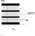
本発明の実施形態で、アンテナパイロット構成は、周波数ブロックの中でパイロット系列と同じアンテナによって伝送される制御情報をパイロット系列が直接的に常に伴うように、他のアンテナパイロット系列に差し込まれた(interleave)異なるOFDMシンボルの中のいくつかのアンテナパイロット系列とともに使用される。この状況は図7の中に示されている。この図では、1つのセルのための時間・周波数グリッドの中の時間方向と周波数方向で、アンテナAおよびBのためのパイロットシンボルはアンテナCおよびDのためのパイロットに差し込まれている。 In an embodiment of the present invention, the antenna pilot configuration is inserted into another antenna pilot sequence so that the pilot sequence always always carries control information transmitted by the same antenna as the pilot sequence in the frequency block ( interleave) Used with several antenna pilot sequences in different OFDM symbols. This situation is shown in FIG. In this figure, pilot symbols for antennas A and B are inserted into pilots for antennas C and D in the time and frequency directions in the time-frequency grid for one cell.
以下に3つの実施形態が示される。 Three embodiments are shown below.
図3に示すように、セクタ毎にちょうど2つのアンテナのある構成では、各アンテナは常にアンテナ特有のパイロットを伝送する。周波数ブロックの幅は12の副搬送波であり、拡散要素がSF=12であるアンテナ毎のパイロット系列が使用される。各パイロットの電力は、すべての利用可能な、または有効な受信状態でのチャネル推定のために十分な|PA|2=|PB|2=1/2である。制御チャネルはちょうど1つのアンテナからのみ送信され、選択されるアンテナはアンテナ間の電力の釣り合わせを達成するために、各周波数ブロックと交替する。 As shown in FIG. 3, in a configuration with exactly two antennas per sector, each antenna always transmits an antenna specific pilot. The width of the frequency block is 12 subcarriers, and a pilot sequence for each antenna whose spreading factor is SF = 12 is used. The power of each pilot is | P A | 2 = | P B | 2 = 1/2 sufficient for channel estimation in all available or valid reception conditions. The control channel is transmitted from exactly one antenna, and the selected antenna alternates with each frequency block to achieve a power balance between the antennas.
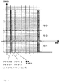
さらに、図6でセクタ毎に4つのアンテナのある構成が示される。周波数ブロックFB1、FB2・・・等毎の制御データは、単一のアンテナから送信される。選択されるアンテナは周波数ブロックと交替し、対応するアンテナパイロットは、例えば周波数ブロックFB1で丸、またはFB2で四角によって示される、第1アンテナ上の第1パイロットと呼ばれる。このアンテナパイロットは|PP|2=1/2の電力を有する。すべての第2アンテナパイロットの合計Σ|PS|2=1/2は、単に1/2でもある。 Further, FIG. 6 shows a configuration with four antennas per sector. The control data for each frequency block FB1, FB2,... Is transmitted from a single antenna. The selected antenna alternates with the frequency block, and the corresponding antenna pilot is referred to as the first pilot on the first antenna, indicated for example by a circle in frequency block FB1 or a square in FB2. This antenna pilot has a power of | P P | 2 = 1/2. The sum of all second antenna pilots Σ | P S | 2 = 1/2 is also simply 1/2.
ビーム形成の場合、1つのみの第2パイロット系列は、|PB|2=|PC|2=|PD|2=1/18または=1/6の残りのすべてのアンテナを介して伝送される。次に図6のFB1で、四角でシンボル化されたアンテナBパイロット、×でシンボル化されたアンテナCパイロットおよび+記号でシンボル化されたアンテナCパイロットは、この周波数ブロックFB1の中でこの場合同一である。次いでビーム内部の振幅は高められ、上述の電力設定の第1ケースでの電力量は
![]()
![]()
![]()
![]()
パイロットのビーム指示アンテナウェイトもまたデータのために使用される。データ伝送のために結合されたチャネル転送関数Htotは、それぞれ第1アンテナと第2アンテナとのチャネル転送関数であるHAとHBtotとの加重された結合によって見つけ出される。例えば、wA=wB=1として、Htot=wAHA+wBHBtotとなる。 The pilot beam pointing antenna weights are also used for data. Channel transfer function H tot coupled for data transmission, are found by weighted combining of H A and H Btot is the channel transfer function between the first antenna and the second antenna, respectively. For example, assuming w A = w B = 1, H tot = w A HA + w B H Btot .
MIMO伝送の場合、電力が|Pp|2=1/2である第1パイロットの他に、例えばFB1の周波数ブロックの内部で、図6の中で四角、×または+記号で示されているような、3つの異なるアンテナ特有のパイロットが使用される。第2パイロットの電力は|PB|2=|PC|2=|PD|2=1/6である。弱められた電力のため、MIMO送信を受信するモバイル端末は、第2パイロットのためのチャネル推定をうまく実行するためには基地局のアンテナに十分近くなければならない。データのMIMO受信のために、いかなる場合でも優良なSINR率が必要であることから、この条件は過度に制限されるべきではない。 In the case of MIMO transmission, in addition to the first pilot whose power is | P p | 2 = 1/2, for example, inside the frequency block of FB1, it is indicated by a square, x or + symbol in FIG. Three different antenna specific pilots are used. The power of the second pilot is | P B | 2 = | P C | 2 = | P D | 2 = 1/6 . Due to the weakened power, the mobile terminal receiving the MIMO transmission must be close enough to the base station antenna to successfully perform channel estimation for the second pilot. This condition should not be overly limited, as a good SINR rate is required in any case for MIMO reception of data.
4つすべてのアンテナを介した送信のとき、全方向の放射を与えるアンテナウェイトが見つけ出されることが可能な、特定のアンテナ構成が与えられる場合、パイロット構成のその他の可能性も実行できる。次に、第1パイロットが見つけ出されたウェイトを用いて4つすべてのアンテナを介して伝送され、共通の制御チャネルもまたそれらのウェイトを用いて伝送される。第1パイロット電力は、例えば|Pp|2=1/2であってよい。さらに第2、第3、第4等のパイロットは、専用の送信データに対応して、異なるアンテナウェイトを備えたすべてのアンテナのうちの単一のものか、またはその一部を介して各々伝送される。例えばMIMO伝送の場合、各々の単一のアンテナパイロットは単一のアンテナの専用データに対応し、第2、第3、第4および第5パイロットの電力は|Pα|2=|Pβ|2=|Pγ|2=|Pδ|2=1/8である。 Other possibilities of the pilot configuration can also be implemented, given a specific antenna configuration where antenna weights that provide omnidirectional radiation can be found when transmitting through all four antennas. The first pilot is then transmitted via all four antennas using the found weights, and a common control channel is also transmitted using those weights. The first pilot power may be, for example, | P p | 2 = 1/2. Further, the second, third, fourth, etc. pilots are each transmitted via a single one of all antennas having different antenna weights or a part thereof corresponding to dedicated transmission data. Is done. For example, for MIMO transmission, each single antenna pilot corresponds to dedicated data for a single antenna, and the power of the second, third, fourth, and fifth pilots is | P α | 2 = | P β | 2 = | Pγ | 2 = | Pδ | 2 = 1/8.
図7の第3の構成で、差し込まれた形で配置された4つのアンテナパイロットが示される。 In the third configuration of FIG. 7, four antenna pilots arranged in an inserted form are shown.
各アンテナは、アンテナ特有のパイロットを常に伝送する。利用可能な、または有効なすべての受信状態でのチャネル推定のために十分な各パイロットの電力は、|PA|2=|PB|2=|PC|2=|PD|2=1/2である。制御チャネルは、制御情報の近くのこの周波数ブロックの中にそれらのパイロットを有する2つのアンテナのうちの1つである、1つのアンテナからまさに伝送され、選択されたアンテナは、アンテナ間の電力の釣り合わせを達成するために、各周波数ブロックと交替する。 Each antenna always transmits an antenna-specific pilot. The power of each pilot sufficient for channel estimation in all available or valid reception states is | P A | 2 = | P B | 2 = | P C | 2 = | P D | 2 = 1/2. The control channel is just transmitted from one antenna, one of the two antennas with their pilots in this frequency block near the control information, and the selected antenna is Alternate with each frequency block to achieve balancing.
この構成は、以前の構成と比較すると、パイロット情報のためにより多くのスペースを必要とし、データ伝送のために残すスペースはより少なくなる。 This configuration requires more space for pilot information and less space for data transmission compared to the previous configuration.
説明した概念とともに、ここに、あらゆる種類の複数アンテナ技術のためのものであり、同時にマイクロスリープ方式をも可能にする柔軟な解決法が存在する。 Along with the described concept, here is a flexible solution that is for all kinds of multi-antenna technologies and at the same time also enables a microsleep scheme.
この解決法は、あらゆる種類の選択的な周波数および多様な周波数の周波数パターンを可能にする、一般的で柔軟な概念である。この解決法はさらに、干渉調整、MIMOおよびビーム形成伝送、ならびに周波数スケジューリングのためのチャネル多重化を可能にし、同時に無線チャネルのチャネル容量を最大限に利用することを可能にする。 This solution is a general and flexible concept that allows all kinds of selective frequencies and frequency patterns of various frequencies. This solution further allows channel multiplexing for interference coordination, MIMO and beamforming transmissions, and frequency scheduling, while at the same time making the best use of the channel capacity of the radio channel.
パイロット対パイロットの干渉を回避することに関して、本方法はここで、例えば必要なネットワークのパイロット計画などの、より高い柔軟性を有する。 With regard to avoiding pilot-to-pilot interference, the method now has greater flexibility, for example the required network pilot planning.
1、2、3 セクタ
1A、1B、1C、1D、2A、2B、2C、2D アンテナ
FB1、FB2、FB3 周波数ブロック
1, 2, 3
Claims (19)
周波数ブロック(FB1〜FB3)の各々の周波数帯域幅に適合するパイロット拡張系列長を備えた隣接するOFDM副搬送波の周波数ブロック(FB1〜FB3)がチャネル多重化のために使用されることと、
パイロット拡張系列長が、逆拡散パイロットを使用したチャネル推定を可能にするために十分に長いこととを特徴とする、方法。 A transmission method using a pilot configured in a channel multiplexing structure in a cellular single frequency network including at least one antenna (1A-1D, 2A-2D) in each cell, comprising:
The adjacent OFDM subcarrier frequency blocks (FB1 to FB3) with pilot extension sequence lengths adapted to the respective frequency bandwidths of the frequency blocks (FB1 to FB3) are used for channel multiplexing;
A method characterized in that the pilot extension sequence length is sufficiently long to allow channel estimation using despread pilots.
前記分配された周波数ブロック(FB1〜FB3)の内部で、アンテナ(1A〜1D、2A〜2D)上の適切な分配によって、アンテナパイロットおよびアンテナウェイトの適切な構成によって、非常に遠距離に配置されたユーザのためでもあり、同時に専用データのためでもある制御データの全方向伝送、ビーム形成もしくはMIMO伝送、または周波数ブロック(FB1〜FB3)とユーザとに依存する通常の伝送が実行されることと、
前記周波数ブロック(FB1〜FB3)の割当が、チャネル推定の測定値、パイロット測定値、干渉測定値、特定のユーザの処理量の増大に関する測定、またはMIMOもしくはビーム形成伝送のために算出された予測処理量に基づくこととを特徴とする、請求項1に記載の方法。 Data portions of the frequency blocks (FB1 to FB3) are allocated to different users in different channel states for beamforming, MIMO transmission, frequency scheduling or interference coordination;
Inside the distributed frequency blocks (FB1 to FB3), with appropriate distribution on the antennas (1A to 1D, 2A to 2D), the antenna pilot and the antenna weight are arranged at a very long distance. Omnidirectional transmission of control data, beam forming or MIMO transmission, or normal transmission depending on the frequency block (FB1 to FB3) and the user, which is also for dedicated users and at the same time for dedicated data; ,
Prediction calculated for allocation of frequency blocks (FB1 to FB3) for channel estimation measurements, pilot measurements, interference measurements, measurements related to increased throughput of a particular user, or MIMO or beamforming transmission The method according to claim 1, wherein the method is based on throughput.
周波数ブロック(FB1〜FB3)の各々の周波数帯域幅に適合し、チャネル推定を可能にするために十分に長いパイロット拡散系列長を備えたパイロットを含むチャネル多重化のために使用される隣接するOFDM副搬送波の周波数ブロック(FB1〜FB3)を受信するための手段を含むことと、
チャネル推定を可能にするために十分に長いパイロット拡散系列長を備えた前記パイロットを使用して、チャネル推定を実行するための手段を含むこととを特徴とする、モバイル端末。 A mobile terminal for transmission using a pilot configured in a channel multiplexing structure in a cellular single frequency network including at least one antenna (1A-1D, 2A-2D) in each cell ,
Adjacent OFDM used for channel multiplexing that includes a pilot with a pilot spreading sequence length that is long enough to accommodate the frequency bandwidth of each of the frequency blocks (FB1-FB3) and to allow channel estimation Including means for receiving subcarrier frequency blocks (FB1-FB3);
A mobile terminal comprising means for performing channel estimation using said pilot with a sufficiently long pilot spreading sequence length to enable channel estimation.
パイロット拡散系列長が周波数ブロック(FB1〜FB3)の各々の周波数帯域幅に適合するようなチャネル多重化のために使用される隣接するOFDM副搬送波の周波数ブロック(FB1〜FB3)を選択するための手段を含むことと、
チャネル推定を可能にするために十分に長いパイロット拡散系列長を選択するための手段を含むこととを特徴とする、基地局。 A base station for transmission using a pilot configured in a channel multiplexing structure in a cellular single frequency network including at least one antenna (1A-1D, 2A-2D) in each cell ,
For selecting adjacent OFDM subcarrier frequency blocks (FB1 to FB3) used for channel multiplexing such that the pilot spreading sequence length matches the frequency bandwidth of each of the frequency blocks (FB1 to FB3). Including means,
A base station comprising means for selecting a pilot spreading sequence length that is long enough to enable channel estimation.
Applications Claiming Priority (1)
| Application Number | Priority Date | Filing Date | Title |
|---|---|---|---|
| EP05292301A EP1780968A1 (en) | 2005-10-28 | 2005-10-28 | OFDM based transmission in a cellular single frequency network with a pilot adapted channel multiplexing structure |
Publications (1)
| Publication Number | Publication Date |
|---|---|
| JP2007124657A true JP2007124657A (en) | 2007-05-17 |
Family
ID=35976498
Family Applications (1)
| Application Number | Title | Priority Date | Filing Date |
|---|---|---|---|
| JP2006290753A Withdrawn JP2007124657A (en) | 2005-10-28 | 2006-10-26 | Cellular single frequency network, base station, mobile terminal, and transmission method in mobile network |
Country Status (4)
| Country | Link |
|---|---|
| US (1) | US20070116095A1 (en) |
| EP (1) | EP1780968A1 (en) |
| JP (1) | JP2007124657A (en) |
| CN (1) | CN1972151A (en) |
Cited By (1)
| Publication number | Priority date | Publication date | Assignee | Title |
|---|---|---|---|---|
| JP2015508601A (en) * | 2012-01-05 | 2015-03-19 | 富士通株式会社 | Linkage resource distribution method, user equipment, multiplex transmission method, and base station |
Families Citing this family (17)
| Publication number | Priority date | Publication date | Assignee | Title |
|---|---|---|---|---|
| US8243850B2 (en) * | 2006-10-24 | 2012-08-14 | Samsung Electronics Co., Ltd. | Method and system for generating reference signals in a wireless communication system |
| CN101400126B (en) * | 2007-09-26 | 2010-08-18 | 大唐移动通信设备有限公司 | Slotted SFN networking method, network side and terminal |
| US7782757B2 (en) * | 2007-10-03 | 2010-08-24 | Industrial Technology Research Institute | Adaptive pilot design for mobile system |
| US8311143B2 (en) * | 2008-03-31 | 2012-11-13 | Qualcomm Incorporated | Scaling methods and apparatus using SNR estimate to avoid overflow |
| WO2009135516A1 (en) | 2008-05-09 | 2009-11-12 | Nokia Siemens Networks Oy | Multi-cell channel estimation in 3g-lte based virtual pilot sequences |
| US8098750B2 (en) * | 2008-07-10 | 2012-01-17 | Infineon Technologies Ag | Method and device for transmitting a plurality of data symbols |
| US8825100B2 (en) | 2008-08-11 | 2014-09-02 | Blackberry Limited | Method and system for providing a power boost for a wireless communication link using a subset of subcarrier frequencies of the wireless communication link channel as a reduced bandwidth channel |
| US8331310B2 (en) * | 2008-08-22 | 2012-12-11 | Qualcomm Incorporated | Systems and methods employing multiple input multiple output (MIMO) techniques |
| WO2010081293A1 (en) | 2009-01-13 | 2010-07-22 | 华为技术有限公司 | Method, device and system for information transmitting and obtaining |
| CN104980976B (en) * | 2009-01-13 | 2019-06-21 | 华为技术有限公司 | The methods, devices and systems that information sends and obtains |
| JP5279677B2 (en) * | 2009-10-13 | 2013-09-04 | 株式会社日立製作所 | Wireless communication system, wireless base station apparatus, and wireless communication method |
| WO2012153994A2 (en) * | 2011-05-10 | 2012-11-15 | 엘지전자 주식회사 | Method for transmitting signal using plurality of antenna ports and transmission end apparatus for same |
| US9137717B2 (en) * | 2012-01-13 | 2015-09-15 | Qualcomm Incorporated | Method and apparatus for managing mobility events in a dual-frequency dual-cell wireless communication network |
| BR112015002718A2 (en) | 2012-08-06 | 2020-04-22 | Ericsson Telefon Ab L M | systems and methods for reporting pilot signal power information in a minimum four-branch system |
| KR102323130B1 (en) * | 2013-11-27 | 2021-11-10 | 삼성전자 주식회사 | Method and apparatus for open-loop mimo transmission in beamforming system |
| DE102015212093B3 (en) * | 2015-06-29 | 2016-12-15 | Kt - Elektronik Klaucke Und Partner Gmbh | Receiver, transmitter and method for determining channel coefficients |
| CN112653479B (en) * | 2020-12-16 | 2022-04-15 | 重庆邮电大学 | DMB baseband SoC supporting single frequency network function |
Family Cites Families (9)
| Publication number | Priority date | Publication date | Assignee | Title |
|---|---|---|---|---|
| JP3581072B2 (en) * | 2000-01-24 | 2004-10-27 | 株式会社エヌ・ティ・ティ・ドコモ | Channel configuration method and base station using the method |
| DE10058336B4 (en) * | 2000-11-24 | 2005-08-04 | Tobias P. Kurpjuhn | Method for beam shaping in systems with array antennas at transmitting and receiving stations |
| JP4454308B2 (en) * | 2001-08-30 | 2010-04-21 | 富士通株式会社 | Multi-carrier CDMA transmission method and base station transmitter |
| CA2459129C (en) * | 2001-08-30 | 2009-09-29 | Ntt Docomo, Inc. | Radio transmission system and method and transmission station apparatus and reception station apparatus used in the radio transmission system |
| CA2428576C (en) * | 2002-05-16 | 2008-10-07 | Ntt Docomo, Inc. | Transmitter for multi-carrier transmission and multi-carrier transmitting method |
| US7986742B2 (en) * | 2002-10-25 | 2011-07-26 | Qualcomm Incorporated | Pilots for MIMO communication system |
| JP3669991B2 (en) * | 2003-02-18 | 2005-07-13 | 三星電子株式会社 | Wireless transceiver, wireless transmission / reception method and program thereof |
| US7302238B2 (en) * | 2003-04-25 | 2007-11-27 | Samsung Electronics Co., Ltd. | Transmit diversity system, method and computer program product |
| US7139328B2 (en) * | 2004-11-04 | 2006-11-21 | Motorola, Inc. | Method and apparatus for closed loop data transmission |
-
2005
- 2005-10-28 EP EP05292301A patent/EP1780968A1/en not_active Withdrawn
-
2006
- 2006-10-26 US US11/586,524 patent/US20070116095A1/en not_active Abandoned
- 2006-10-26 JP JP2006290753A patent/JP2007124657A/en not_active Withdrawn
- 2006-10-27 CN CNA2006101425038A patent/CN1972151A/en active Pending
Cited By (1)
| Publication number | Priority date | Publication date | Assignee | Title |
|---|---|---|---|---|
| JP2015508601A (en) * | 2012-01-05 | 2015-03-19 | 富士通株式会社 | Linkage resource distribution method, user equipment, multiplex transmission method, and base station |
Also Published As
| Publication number | Publication date |
|---|---|
| US20070116095A1 (en) | 2007-05-24 |
| CN1972151A (en) | 2007-05-30 |
| EP1780968A1 (en) | 2007-05-02 |
Similar Documents
| Publication | Publication Date | Title |
|---|---|---|
| JP2007124657A (en) | Cellular single frequency network, base station, mobile terminal, and transmission method in mobile network | |
| KR101294116B1 (en) | Point to multipoint device for communication with a plurality of telecommunications units | |
| EP1597852B1 (en) | Pilot signals for use in multi-sector cells | |
| EP1175802B1 (en) | A method of directional radio communication | |
| EP2052562B1 (en) | Method and apparatus for scheduling resources and avoiding interference in a multi-cellular wireless communication system | |
| US9603102B2 (en) | Method of transmitting pilot tones in a multi-sector cell, including null pilot tones, for generating channel quality indicators | |
| EP1700398B1 (en) | A measurement method for spatial scheduling | |
| US8565773B2 (en) | Method and apparatus for enabling soft handoff in an OFDMA-based communication system | |
| EP1869797B1 (en) | High rate packet data spatial division multiple access (sdma) | |
| EP1343339A2 (en) | Channel structure having a shared downlink channel in a mobile communication system | |
| KR100749448B1 (en) | Method and system for selecting switched beam using maximum received power | |
| EP1876847A1 (en) | A method for scheduling of user terminals in an SDMA capable radio communication network, a base station and a network therefor |
Legal Events
| Date | Code | Title | Description |
|---|---|---|---|
| A300 | Application deemed to be withdrawn because no request for examination was validly filed |
Free format text: JAPANESE INTERMEDIATE CODE: A300 Effective date: 20100105 |