JP2007122108A - Control of storage system using disk drive device with self-check function - Google Patents
Control of storage system using disk drive device with self-check function Download PDFInfo
- Publication number
- JP2007122108A JP2007122108A JP2005309198A JP2005309198A JP2007122108A JP 2007122108 A JP2007122108 A JP 2007122108A JP 2005309198 A JP2005309198 A JP 2005309198A JP 2005309198 A JP2005309198 A JP 2005309198A JP 2007122108 A JP2007122108 A JP 2007122108A
- Authority
- JP
- Japan
- Prior art keywords
- timing
- mode
- test
- disk drive
- operation mode
- Prior art date
- Legal status (The legal status is an assumption and is not a legal conclusion. Google has not performed a legal analysis and makes no representation as to the accuracy of the status listed.)
- Pending
Links
Images


Classifications
-
- G—PHYSICS
- G11—INFORMATION STORAGE
- G11B—INFORMATION STORAGE BASED ON RELATIVE MOVEMENT BETWEEN RECORD CARRIER AND TRANSDUCER
- G11B20/00—Signal processing not specific to the method of recording or reproducing; Circuits therefor
- G11B20/10—Digital recording or reproducing
- G11B20/18—Error detection or correction; Testing, e.g. of drop-outs
- G11B20/1816—Testing
-
- G—PHYSICS
- G06—COMPUTING; CALCULATING OR COUNTING
- G06F—ELECTRIC DIGITAL DATA PROCESSING
- G06F11/00—Error detection; Error correction; Monitoring
- G06F11/22—Detection or location of defective computer hardware by testing during standby operation or during idle time, e.g. start-up testing
- G06F11/2205—Detection or location of defective computer hardware by testing during standby operation or during idle time, e.g. start-up testing using arrangements specific to the hardware being tested
- G06F11/2221—Detection or location of defective computer hardware by testing during standby operation or during idle time, e.g. start-up testing using arrangements specific to the hardware being tested to test input/output devices or peripheral units
Landscapes
- Engineering & Computer Science (AREA)
- General Engineering & Computer Science (AREA)
- Theoretical Computer Science (AREA)
- Signal Processing (AREA)
- Computer Hardware Design (AREA)
- Quality & Reliability (AREA)
- Physics & Mathematics (AREA)
- General Physics & Mathematics (AREA)
- Signal Processing For Digital Recording And Reproducing (AREA)
Abstract
Description
本発明は、セルフチェック機能を有するディスクドライブ装置を用いたストレージシステムの制御技術に関する。 The present invention relates to a storage system control technique using a disk drive device having a self-check function.
従来より、ディスクドライブ装置を用いたストレージシステムが利用されている。ディスクドライブ装置の中には、セルフチェック(セルフテスト)機能を有するものがある。このような機能(技術)としては、S.M.A.R.T.(Self Monitoring Analysis and Reporting Technology)が知られている。このようなセルフチェック機能は、例えば、ディスクドライブの交換に利用されている(特許文献1参照)。 Conventionally, a storage system using a disk drive device has been used. Some disk drive devices have a self-check (self-test) function. As such a function (technology), S.M.A.R.T. (Self Monitoring Analysis and Reporting Technology) is known. Such a self-check function is used, for example, for disk drive replacement (see Patent Document 1).
ところで、従来のストレージシステムでは、そのストレージシステムに設けられた複数のディスクドライブ装置の動作状態は、基本的にスピンアップ状態である。従って、セルフチェックに伴って、ディスクドライブ装置がスピンアップされることは少なかった。一方、近年では、MAID(Massive Array of Inactive Disk)技術を適用したストレージシステムが利用される場合がある。MAIDでは、複数のディスクドライブ装置の中の、アクセスの無いディスクドライブ装置の中の少なくとも一部がスピンダウンされる。このようなMAIDを用いることによって、消費電力を抑え、ストレージシステムの高密度化(省スペース化)を実現し、さらには、ディスクドライブ装置の長寿命化を実現することも可能となる。ここで、ディスクドライブ装置の最新の状態を取得するためには、セルフチェックが繰り返し実行される。ところが、セルフチェックの実行によって、ディスクドライブ装置に負荷がかかる。その結果、セルフチェックに起因してディスクドライブ装置の寿命が短縮される可能性があった。特に、MAID技術を適用したストレージシステムでは、セルフチェックに伴ってスピンアップやスピンダウンが実行される場合があり、その結果、ディスクドライブ装置に大きな負荷がかかる可能性があった。 Incidentally, in the conventional storage system, the operation state of the plurality of disk drive devices provided in the storage system is basically a spin-up state. Therefore, the disk drive device is rarely spun up with the self-check. On the other hand, in recent years, a storage system to which MAID (Massive Array of Inactive Disk) technology is applied may be used. In MAID, at least some of the disk drive devices without access among the plurality of disk drive devices are spun down. By using such a MAID, it is possible to reduce power consumption, increase the density (space saving) of the storage system, and further extend the life of the disk drive device. Here, in order to acquire the latest state of the disk drive device, the self-check is repeatedly executed. However, the execution of the self-check places a load on the disk drive device. As a result, the life of the disk drive device may be shortened due to the self-check. In particular, in a storage system to which the MAID technology is applied, spin-up and spin-down may be executed along with the self-check, and as a result, a large load may be applied to the disk drive device.
なお、このような問題は、セルフチェックに伴ってスピンアップやスピンダウンが実行される場合に限らず、スピンアップやスピンダウンを伴わないセルフチェックが実行される場合にも共通する問題であった。また、このような問題は、MAIDのように一部のディスクドライブ装置がスピンダウンされるストレージシステムに限らず、ディスクドライブ装置がスピンダウンされないストレージシステムにも共通する問題であった。 Such a problem is not limited to a case where a spin-up or spin-down is performed in conjunction with a self-check, but is a common problem when a self-check without a spin-up or spin-down is performed. . Such a problem is not limited to a storage system in which some disk drive devices are spun down, such as MAID, but is also a problem common to storage systems in which disk drive devices are not spun down.
本発明は、上記の課題を解決するためになされたものであり、セルフチェックの結果の利用時点での信頼性と、セルフチェックに起因するディスクドライブ装置の寿命の短縮抑制と、のバランスをとることができる技術を提供することである。 The present invention has been made to solve the above problems, and balances the reliability at the time of use of the result of the self-check and the suppression of shortening the life of the disk drive device due to the self-check. Is to provide technology that can.
上述の課題の少なくとも一部を解決するため、本発明のストレージシステムは、データの読み書きが可能な記憶領域をホストコンピュータに提供するストレージシステムであって、ディスクドライブ装置であって、前記記憶領域と、前記ディスクドライブ装置の動作のテスト処理を実行するテスト実行部と、を有するディスクドライブ装置と、前記テスト実行部に前記テスト処理の実行指示を送信するテスト指示部と、前記テスト処理の結果を取得する結果取得部と、前記ディスクドライブ装置の動作状況と、前記ディスクドライブ装置の動作履歴と、の少なくとも一方に関する稼働情報を取得する稼働情報取得部と、を備え、前記テスト指示部は、前記テスト処理実行指示のタイミング決定のモードであるタイミングモードとして、前記稼働情報の少なくとも一部の第1稼働情報に基づいて前記タイミングを決定する第1タイミングモードを有する。 In order to solve at least a part of the above-described problems, a storage system according to the present invention is a storage system that provides a host computer with a storage area where data can be read and written, and is a disk drive device that includes the storage area and the storage area. A test execution unit that executes a test process of the operation of the disk drive device, a test instruction unit that transmits an execution instruction of the test process to the test execution unit, and a result of the test process An operation information acquisition unit that acquires operation information related to at least one of a result acquisition unit, an operation status of the disk drive device, and an operation history of the disk drive device, and the test instruction unit includes: As the timing mode, which is the mode for determining the timing of the test process execution instruction, Having a first timing mode of determining the timing based at least in part a first operation information of the information.
このストレージシステムによれば、テスト処理のタイミングが、ディスクドライブ装置の動作状況と、ディスクドライブ装置の動作履歴と、の少なくとも一方に関する稼働情報の少なくとも一部の第1稼働情報に基づいて決定されるので、セルフチェックの結果の利用時点での信頼性と、セルフチェックに起因するディスクドライブ装置の寿命の短縮抑制と、のバランスをとることができる。 According to this storage system, the timing of the test process is determined based on the first operation information of at least a part of the operation information related to at least one of the operation status of the disk drive device and the operation history of the disk drive device. Therefore, it is possible to balance the reliability at the time of using the result of the self-check and the suppression of shortening the life of the disk drive device due to the self-check.
上記ストレージシステムにおいて、前記テスト指示部は、さらに、前記タイミングモードとして、前記第1タイミングモードとは異なるタイミングを決定する第2タイミングモードを有し、前記テスト指示部は、前記タイミングモードの選択の契機に応じて、前記稼働情報の少なくとも一部の第2稼働情報が、与えられた第1タイミング条件を満たしているか否かを判断し、(i)前記第1タイミング条件が満たされている場合には、前記第1タイミングモードに従って前記テスト処理の実行指示のタイミングを決定し、(ii)前記第1タイミング条件が満たされていない場合には、前記第2タイミングモードに従って前記テスト処理の実行指示のタイミングを決定することとしてもよい。 In the storage system, the test instruction unit further includes a second timing mode for determining a timing different from the first timing mode as the timing mode, and the test instruction unit selects the timing mode. According to a trigger, it is determined whether at least a part of the second operation information of the operation information satisfies a given first timing condition, and (i) the first timing condition is satisfied Determining the timing of execution of the test process in accordance with the first timing mode, and (ii) instructing execution of the test process in accordance with the second timing mode if the first timing condition is not satisfied. The timing may be determined.
この構成によれば、稼働情報の少なくとも一部の第2稼働情報に基づいて、タイミングを決定するモードが選択されるので、セルフチェックの結果の利用時点での信頼性と、セルフチェックに起因するディスクドライブ装置の寿命の短縮抑制と、のバランスをとることができる。 According to this configuration, since the mode for determining the timing is selected based on at least part of the second operation information of the operation information, the reliability at the time of using the self-check result and the self-check result. A balance between shortening the life of the disk drive device can be achieved.
上記ストレージシステムにおいて、前記テスト指示部は、前記第2タイミングモードにおいて、一定時間間隔毎に前記テスト処理の実行指示を送信することとしてもよい。 In the storage system, the test instruction unit may transmit an instruction to execute the test process at regular time intervals in the second timing mode.
この構成によれば、第2タイミングモードでは、一定時間間隔でテスト処理が実行されるので、セルフチェックの結果の利用時点での信頼性を高めることができる。 According to this configuration, in the second timing mode, the test process is executed at regular time intervals, so that the reliability at the time of using the self-check result can be improved.
上記各ストレージシステムにおいて、前記ディスクドライブ装置は、アップ動作モードとダウン動作モードとを含む複数の動作モードを有し、前記アップ動作モードは、前記ダウン動作モードと比べて、前記ディスクドライブ装置の読み書きの実行時の状態に近い状態で動作する動作モードであり、前記第2稼働情報は、前記ディスクドライブ装置の動作モードが前記アップ動作モードから前記ダウン動作モードへ切り替わった回数と、前記ディスクドライブ装置の動作モードが前記ダウン動作モードから前記アップ動作モードへ切り替わった回数と、前記ディスクドライブ装置の電源がONからOFFへ切り替わった回数と、前記ディスクドライブ装置の電源がOFFからONへ切り替わった回数と、前記ディスクドライブ装置を対象として読み書きされたデータ量に正の相関のある値と、の中の少なくとも一部のパラメータを含み、前記第1タイミング条件は、前記第2稼働情報に含まれる各パラメータの少なくとも一部がそれぞれの閾値を超えていることを含むことが好ましい。 In each of the above storage systems, the disk drive device has a plurality of operation modes including an up operation mode and a down operation mode, and the up operation mode is read / write of the disk drive device as compared with the down operation mode. The second operation information includes the number of times the operation mode of the disk drive device has been switched from the up operation mode to the down operation mode, and the disk drive device. The number of times the operation mode is switched from the down operation mode to the up operation mode, the number of times the power of the disk drive device is switched from ON to OFF, and the number of times the power of the disk drive device is switched from OFF to ON Targeting the disk drive device A value having a positive correlation with the amount of data read and written, and at least a part of the parameters, and the first timing condition includes at least a part of each parameter included in the second operation information as a threshold value It is preferable to include exceeding.
アップ/ダウンの回数と、電源ON/OFFの回数と、読み書きされたデータ量に正の相関のある値とは、ディスクドライブ装置200の寿命との関連性が特に強い。従って、この構成によれば、タイミングモード選択の条件に、これらのパラメータの少なくとも一部が用いられるので、ディスクドライブ装置の状態の適した選択を行うことができる。
The value that is positively correlated with the number of times of up / down, the number of times of power ON / OFF, and the amount of data read / written is particularly strongly related to the life of the
上記ストレージシステムにおいて、さらに、前記ディスクドライブ装置は、アップ動作モードとダウン動作モードとを含む複数の動作モードを有し、前記アップ動作モードは、前記ダウン動作モードと比べて、前記ディスクドライブ装置の読み書きの実行時の状態に近い状態で動作する動作モードであり、前記稼働情報の少なくとも一部の第3稼働情報は、前記ディスクドライブ装置の現行の動作モードを含み、前記結果取得部は、前記テスト処理結果の参照要求に応じて前記ディスクドライブ装置の現行の動作モードが前記アップ動作モードであるか否かを判断するとともに、(A)前記動作モードが前記アップ動作モードである場合には、前記テスト処理の実行指示を前記テスト実行部に送信することによって新たな前記テスト処理の結果を取得するとともに、取得した前記テスト処理の結果を提供し、(B)前記動作モードが前記アップ動作モードでない場合には、さらに、前記第3稼働情報が、与えられた実行可能条件を満たしているか否かを判断し、(B1)前記実行可能条件が満たされている場合には、前記テスト処理の実行指示を前記テスト実行部に送信することによって新たな前記テスト処理の結果を取得するとともに、取得した前記テスト処理の結果を提供し、(B2)前記実行可能条件が満たされていない場合には、前記テスト処理の実行指示を前記テスト実行部に送信せずに、前記テスト指示部の指示に従って実行されたテスト処理の結果であって取得済みの結果を、提供することとしてもよい。 In the above storage system, the disk drive device further has a plurality of operation modes including an up operation mode and a down operation mode, and the up operation mode is compared with the down operation mode in the disk drive device. It is an operation mode that operates in a state close to the state at the time of execution of reading and writing, at least a part of the third operation information of the operation information includes a current operation mode of the disk drive device, the result acquisition unit, In response to a test process result reference request, it is determined whether the current operation mode of the disk drive device is the up operation mode, and (A) when the operation mode is the up operation mode, By sending an instruction to execute the test process to the test execution unit, a new test process result is transmitted. And (B) when the operation mode is not the up operation mode, the third operation information further satisfies a given executable condition. (B1) When the executable condition is satisfied, a test process execution instruction is transmitted to the test execution unit to obtain a new test process result. (B2) If the executable condition is not satisfied, (B2) without sending an instruction to execute the test process to the test execution unit; It is also possible to provide an acquired result that is a result of the test process executed in accordance with the instruction.
この構成によれば、テスト処理結果の参照要求が発行された場合に、新たなテスト処理の結果を提供するか、取得済みのテスト結果を提供するかが、稼働情報の少なくとも一部の第3稼働情報(ディスクドライブ装置の現行の動作モードを含む)に基づいて決定されるので、セルフチェックの結果の利用時点での信頼性と、セルフチェックに起因するディスクドライブ装置の寿命の短縮抑制と、のバランスをとることができる。 According to this configuration, when a test process result reference request is issued, whether to provide a new test process result or an acquired test result, the third part of at least a part of the operation information. Since it is determined based on the operation information (including the current operation mode of the disk drive device), the reliability at the time of use of the result of the self-check, the suppression of shortening the life of the disk drive device due to the self-check, Can be balanced.
上記ストレージシステムにおいて、前記第3稼働情報は、さらに、前記ディスクドライブ装置の動作モードが前記アップ動作モードから前記ダウン動作モードへ切り替わった回数と、前記ディスクドライブ装置の動作モードが前記ダウン動作モードから前記アップ動作モードへ切り替わった回数と、前記ディスクドライブ装置の電源がONからOFFへ切り替わった回数と、前記ディスクドライブ装置の電源がOFFからONへ切り替わった回数と、前記ディスクドライブ装置を対象として読み書きされたデータ量に正の相関のある値と、の中の少なくとも一部のパラメータを含み、前記実行可能条件は、前記第3稼働情報に含まれる各パラメータがそれぞれの閾値以下であることを含む、ことが好ましい。 In the storage system, the third operation information further includes the number of times the operation mode of the disk drive device has been switched from the up operation mode to the down operation mode, and the operation mode of the disk drive device from the down operation mode. The number of times of switching to the up operation mode, the number of times that the power of the disk drive device has been switched from ON to OFF, the number of times that the power of the disk drive device has been switched from OFF to ON, and the read / write to the disk drive device And at least some of the parameters that are positively correlated with the amount of data obtained, and the executable condition includes that each parameter included in the third operation information is equal to or less than a threshold value. It is preferable.
アップ/ダウンの回数と、電源ON/OFFの回数と、読み書きされたデータ量に正の相関のある値とは、ディスクドライブ装置200の寿命との関連性が特に強い。従って、この構成によれば、テスト結果の選択の条件に、これらのパラメータの少なくとも一部が用いられるので、ディスクドライブ装置の状態の適した選択を行うことができる。
The value that is positively correlated with the number of times of up / down, the number of times of power ON / OFF, and the amount of data read / written is particularly strongly related to the life of the
上記ストレージシステムにおいて、前記結果取得部は、与えられた閾値設定要求に応じて前記閾値を設定することとしてもよい。 In the storage system, the result acquisition unit may set the threshold according to a given threshold setting request.
この構成によれば、閾値が要求に応じて設定されるので、結果取得部は、ストレージシステムの利用状況に適した閾値を用いることができる。 According to this configuration, since the threshold is set according to the request, the result acquisition unit can use a threshold suitable for the usage status of the storage system.
上記各ストレージシステムにおいて、前記ホストコンピュータと前記ディスクドライブ装置とに接続されるとともに、前記ホストコンピュータの要求に応じて前記ディスクドライブ装置を制御するストレージ制御部を備え、前記テスト指示部と前記結果取得部と前記稼働情報取得部とは前記ストレージ制御部に設けられており、前記ディスクドライブ装置は、第1と第2のディスクドライブ装置を含み、前記実行可能条件は、第1と第2の実行可能条件を含み、前記結果取得部は、前記第1実行可能条件を用いて前記第1ディスクドライブ装置に対する処理を行い、前記第2実行可能条件を用いて前記第2ディスクドライブ装置に対する処理を行うこととしてもよい。 Each of the storage systems includes a storage control unit that is connected to the host computer and the disk drive device and controls the disk drive device in response to a request of the host computer, the test instruction unit and the result acquisition And the operation information acquisition unit are provided in the storage control unit, the disk drive device includes first and second disk drive devices, and the executable condition is the first and second execution conditions The result obtaining unit includes processing for the first disk drive device using the first executable condition, and performs processing for the second disk drive device using the second executable condition. It is good as well.
この構成によれば、結果取得部は、各ディスクドライブ装置に適した結果を取得することができる。 According to this configuration, the result acquisition unit can acquire a result suitable for each disk drive device.
上記ストレージシステムにおいて、前記ディスクドライブ装置は、アップ動作モードとダウン動作モードとを含む複数の動作モードを有し、前記アップ動作モードは、前記ダウン動作モードと比べて、前記ディスクドライブ装置の読み書きの実行時の状態に近い状態で動作する動作モードであり、前記第1稼働情報は、前記ディスクドライブ装置の動作モードの前記アップ動作モードから前記ダウン動作モードへの移行の契機であるダウン契機を含み、前記テスト指示部は、前記第1タイミングモードとして、ダウンタイミングモードを有し、前記テスト指示部は、前記ダウンタイミングモードにおいて、前記ダウン契機に応じて、前記テスト処理を実行する旨の指示を前記テスト実行部に送信することによって、前記テスト実行部に前記動作モードの移行前に前記テスト処理を実行させることとしてもよい。 In the storage system, the disk drive device has a plurality of operation modes including an up operation mode and a down operation mode, and the up operation mode is read / write of the disk drive device as compared with the down operation mode. The operation mode is an operation mode that operates in a state close to a state at the time of execution, and the first operation information includes a down trigger that is a trigger for transition of the operation mode of the disk drive device from the up operation mode to the down operation mode. The test instruction unit has a down timing mode as the first timing mode, and the test instruction unit gives an instruction to execute the test process in response to the down trigger in the down timing mode. The operation to the test execution unit by transmitting to the test execution unit The test process may be executed before the mode transition.
この構成によれば、動作モードがアップ動作モードからダウン動作モードへの移行の契機に応じてテスト処理が実行されるので、テスト結果の利用時点での信頼性の低下を抑制しつつ、取得済みのテスト結果を、新たなテスト処理の結果の代わりに利用することができる。 According to this configuration, the test process is executed in response to the transition of the operation mode from the up operation mode to the down operation mode. Therefore, the acquisition has been performed while suppressing a decrease in reliability at the time of using the test result. This test result can be used in place of the result of a new test process.
上記ストレージシステムにおいて、前記ディスクドライブ装置は、アップ動作モードとダウン動作モードとを含む複数の動作モードを有し、前記アップ動作モードは、前記ダウン動作モードと比べて、前記ディスクドライブ装置の読み書きの実行時の状態に近い状態で動作する動作モードであり、前記第1稼働情報は、前記ディスクドライブ装置の動作モードの前記ダウン動作モードから前記アップ動作モードへの移行の契機であるアップ契機を含み、前記テスト指示部は、前記第1タイミングモードとして、アップタイミングモードを有し、前記テスト指示部は、前記アップタイミングモードにおいて、前記アップ契機に応じて、前記テスト処理を実行する旨の指示を前記テスト実行部に送信することによって、前記テスト実行部に前記動作モードの移行後に前記テスト処理を実行させることとしてもよい。 In the storage system, the disk drive device has a plurality of operation modes including an up operation mode and a down operation mode, and the up operation mode is read / write of the disk drive device as compared with the down operation mode. It is an operation mode that operates in a state close to the state at the time of execution, and the first operation information includes an up opportunity that is an opportunity for transition of the operation mode of the disk drive device from the down operation mode to the up operation mode. The test instruction unit has an up timing mode as the first timing mode, and the test instruction unit issues an instruction to execute the test process in response to the up trigger in the up timing mode. The operation to the test execution unit by transmitting to the test execution unit The test process may be executed after the mode transition.
この構成によれば、動作モードがダウン動作モードからアップ動作モードへの移行の契機に応じてテスト処理が実行されるので、テスト結果の利用時点での信頼性の低下を抑制しつつ、取得済みのテスト結果を、新たなテスト処理の結果の代わりに利用することができる。 According to this configuration, test processing is executed in response to the transition of the operation mode from the down operation mode to the up operation mode, so acquisition of the test result is suppressed while suppressing a decrease in reliability. This test result can be used in place of the result of a new test process.
上記ストレージシステムにおいて、前記第1稼働情報は、前記ディスクドライブ装置を対象とする読み書きの契機を含み、前記テスト指示部は、前記第1タイミングモードとして、アクセスタイミングモードを有し、前記テスト指示部は、前記アクセスタイミングモードにおいて、前記テスト処理の指示の要否確認の契機に応じて、前記ディスクドライブ装置を対象とする読み書きの契機に応じて前記テスト処理の実行指示を前記テスト実行部に送信することとしてもよい。 In the storage system, the first operation information includes a read / write opportunity for the disk drive device, and the test instruction unit has an access timing mode as the first timing mode, and the test instruction unit In the access timing mode, the test process execution instruction is transmitted to the test execution unit in response to the read / write trigger for the disk drive device in response to the necessity confirmation of the test process instruction. It is good to do.
この構成によれば、テスト処理がアクセスに同期して実行されるので、テスト処理の実行に起因するディスクドライブ装置の寿命の短縮を抑えることができる。 According to this configuration, since the test process is executed in synchronization with the access, the shortening of the life of the disk drive device due to the execution of the test process can be suppressed.
上記ストレージシステムにおいて、前記テスト指示部は、前記第1タイミングモードとして、状況実行タイミングモードを有し、前記テスト指示部は、前記状況実行タイミングモードにおいて、前記テスト処理の指示の要否確認の契機に応じて、前記第1稼働情報が、与えられた状況実行条件を満たしているか否かを判断し、(i)前記状況実行条件が満たされている場合には、前記テスト処理の実行指示を前記テスト実行部に送信し、(ii)前記状況実行条件が満たされていない場合には、前記テスト処理の実行指示を送信せずに、次の前記要否確認契機を待つこととしてもよい。 In the storage system, the test instruction unit has a situation execution timing mode as the first timing mode, and the test instruction unit triggers confirmation of necessity of the test processing instruction in the situation execution timing mode. In response, the first operation information determines whether or not the given situation execution condition is satisfied. (I) If the situation execution condition is satisfied, an instruction to execute the test process is issued. It may be transmitted to the test execution unit, and (ii) when the condition execution condition is not satisfied, the next necessity confirmation opportunity may be waited without transmitting the execution instruction of the test process.
この構成によれば、第1稼働情報が、与えられた状況実行条件を満たしているか否かに応じて、テスト処理が実行されるか否かが決定されるので、セルフチェックの結果の利用時点での信頼性と、テストに起因するディスクドライブ装置の寿命の短縮抑制と、のバランスをとることができる。 According to this configuration, whether or not the test process is executed is determined depending on whether or not the first operation information satisfies the given situation execution condition. Therefore, it is possible to balance the reliability of the disk drive with the reduction in the life of the disk drive device due to the test.
上記ストレージシステムにおいて、前記第1稼働情報は、前記ディスクドライブ装置を対象とする読み書きの頻度に相関のある頻度パラメータを含み、前記状況実行条件は、前記頻度パラメータが表す頻度が閾値未満であることを含むこととしてもよい。 In the storage system, the first operation information includes a frequency parameter correlated with a read / write frequency for the disk drive device, and the status execution condition includes that the frequency represented by the frequency parameter is less than a threshold value. It is good also as including.
この構成によれば、現時点での読み書きの頻度が比較的高い場合にはテスト処理が実行されないので、テスト処理の実行に起因するディスクドライブ装置の寿命の短縮を抑えることができる。 According to this configuration, since the test process is not executed when the read / write frequency at this time is relatively high, it is possible to suppress the shortening of the life of the disk drive device due to the execution of the test process.
上記ストレージシステムにおいて、前記ディスクドライブ装置は、アップ動作モードとダウン動作モードとを含む複数の動作モードを有し、前記アップ動作モードは、前記ダウン動作モードと比べて、前記ディスクドライブ装置の読み書きの実行時の状態に近い状態で動作する動作モードであり、前記第1稼働情報は、前記ディスクドライブ装置を対象とする読み書きの契機と、前記ディスクドライブ装置の現行の動作モードと、を含み、前記テスト指示部は、前記第1タイミングモードとして、状況判定モードを有し、前記テスト指示部は、前記状況判定モードにおいて、前記テスト処理の指示の要否確認の契機に応じて、前記ディスクドライブ装置の現行の動作モードが前記ダウン動作モードであるか否かを判断し、(A)前記動作モードが前記ダウン動作モードではない場合には、前記テスト処理の実行指示を前記テスト実行部に送信し、(B)前記動作モードが前記ダウン動作モードである場合には、さらに、前記第1稼働情報が、与えられた状況判定条件を満たしているか否かを判断し、(B1)前記状況判定条件が満たされている場合には、前記テスト処理の実行指示を前記テスト実行部に送信し、(B2)前記状況判定条件が満たされていない場合には、前記テスト処理の実行指示の送信を保留し、前記ディスクドライブ装置を対象とする読み書きの契機に応じて前記テスト処理の実行指示を前記テスト実行部に送信することとしてもよい。 In the storage system, the disk drive device has a plurality of operation modes including an up operation mode and a down operation mode, and the up operation mode is read / write of the disk drive device as compared with the down operation mode. An operation mode that operates in a state close to a state at the time of execution, and the first operation information includes a read / write trigger for the disk drive device and a current operation mode of the disk drive device, The test instruction unit has a situation determination mode as the first timing mode, and the test instruction unit is configured to check the necessity of the instruction for the test process in the situation determination mode. To determine whether the current operation mode is the down operation mode, and (A) the operation mode When the operation mode is not the down operation mode, an instruction to execute the test process is transmitted to the test execution unit. (B) When the operation mode is the down operation mode, the first operation information is further transmitted. Determines whether or not a given situation determination condition is satisfied. (B1) If the condition determination condition is satisfied, an instruction to execute the test process is transmitted to the test execution unit. B2) If the condition determination condition is not satisfied, transmission of the test process execution instruction is suspended, and the test process execution instruction is sent to the test according to the read / write trigger for the disk drive device. It is good also as transmitting to an execution part.
この構成によれば、テスト処理の実行タイミングが、ディスクドライブ装置を対象とする読み書きの契機と、ディスクドライブ装置の現行の動作モードと、を含む第1稼働情報に基づいて決定されるので、セルフチェックの結果の利用時点での信頼性と、セルフチェックに起因するディスクドライブ装置の寿命の短縮抑制と、のバランスをとることができる。 According to this configuration, the execution timing of the test process is determined based on the first operation information including the read / write timing for the disk drive device and the current operation mode of the disk drive device. It is possible to balance the reliability at the time of use of the check result with the suppression of shortening of the life of the disk drive device due to the self-check.
上記ストレージシステムにおいて、前記第1稼働情報は、前記ディスクドライブ装置の動作モードが前記アップ動作モードから前記ダウン動作モードへ切り替わった回数と、前記ディスクドライブ装置の動作モードが前記ダウン動作モードから前記アップ動作モードへ切り替わった回数と、前記ディスクドライブ装置の電源がONからOFFへ切り替わった回数と、前記ディスクドライブ装置の電源がOFFからONへ切り替わった回数と、前記ディスクドライブ装置を対象として読み書きされたデータ量に正の相関のある値と、の中の少なくとも一部のパラメータを含み、前記状況判定条件は、前記第1稼働情報に含まれる各パラメータがそれぞれの閾値以下であることを含むことが好ましい。 In the storage system, the first operation information includes the number of times the operation mode of the disk drive device has been switched from the up operation mode to the down operation mode, and the operation mode of the disk drive device from the down operation mode to the up operation mode. The number of times of switching to the operation mode, the number of times the power of the disk drive device was switched from ON to OFF, the number of times the power of the disk drive device was switched from OFF to ON, and the read / write for the disk drive device A value having a positive correlation with the data amount and at least some of the parameters, and the situation determination condition includes that each parameter included in the first operation information is equal to or less than a threshold value. preferable.
アップ/ダウンの回数と、電源ON/OFFの回数と、読み書きされたデータ量に正の相関のある値とは、ディスクドライブ装置200の寿命との関連性が特に強い。従って、この構成によれば、テスト処理のタイミングの決定に、これらのパラメータの少なくとも一部が用いられるので、ディスクドライブ装置の状態に適したタイミングを決定することができる。
The value that is positively correlated with the number of times of up / down, the number of times of power ON / OFF, and the amount of data read / written is particularly strongly related to the life of the
上記各ストレージシステムにおいて、さらに、前記ホストコンピュータと前記ディスクドライブ装置とに接続されるとともに、前記ホストコンピュータの要求に応じて前記ディスクドライブ装置を制御するストレージ制御部を備え、前記テスト指示部と前記結果取得部と前記稼働情報取得部とは前記ストレージ制御部に設けられており、前記ディスクドライブ装置は、第1と第2のディスクドライブ装置を含み、前記条件は、第1ドライブ用と第2ドライブ用の条件を含み、前記テスト指示部は、前記第1ドライブ用条件を用いて前記第1ディスクドライブ装置に対する処理を行い、前記第2ドライブ用条件を用いて前記第2ディスクドライブ装置に対する処理を行うこととしてもよい。 Each of the storage systems further includes a storage control unit that is connected to the host computer and the disk drive device and controls the disk drive device in response to a request from the host computer, the test instruction unit, The result acquisition unit and the operation information acquisition unit are provided in the storage control unit, the disk drive device includes first and second disk drive devices, and the condition is for the first drive and the second drive Including a drive condition, wherein the test instruction unit performs a process for the first disk drive device using the first drive condition, and a process for the second disk drive device using the second drive condition. It is good also as performing.
この構成によれば、テスト指示部は、各ディスクドライブ装置に適したタイミングで指示を行うことができる。 According to this configuration, the test instruction unit can issue an instruction at a timing suitable for each disk drive device.
上記各ストレージシステムにおいて、前記テスト指示部は、与えられた閾値設定要求に応じて前記閾値を設定することとしてもよい。 In each of the above storage systems, the test instruction unit may set the threshold according to a given threshold setting request.
この構成によれば、閾値が要求に応じて設定されるので、テスト指示部は、ストレージシステムの利用状況に適した閾値を用いることができる。 According to this configuration, since the threshold value is set according to the request, the test instruction unit can use a threshold value suitable for the usage status of the storage system.
上記各ストレージシステムにおいて、前記ホストコンピュータと前記ディスクドライブ装置とに接続されるとともに、前記ホストコンピュータの要求に応じて前記ディスクドライブ装置を制御するストレージ制御部を備え、前記結果取得部は前記ストレージ制御部に設けられており、前記テスト指示部と前記稼働情報取得部とは前記ディスクドライブ装置に設けられており、前記ストレージ制御部は、さらに、与えられた閾値設定要求に応じて前記テスト指示部に前記閾値設定要求を送信する閾値設定部を有し、前記テスト指示部は、受信した前記閾値設定要求に応じて前記閾値を設定することとしてもよい。 Each of the storage systems includes a storage control unit that is connected to the host computer and the disk drive device and controls the disk drive device in response to a request from the host computer, and the result acquisition unit includes the storage control unit The test instruction unit and the operation information acquisition unit are provided in the disk drive device, and the storage control unit further includes the test instruction unit in response to a given threshold setting request. The threshold value setting unit that transmits the threshold value setting request may be included, and the test instruction unit may set the threshold value according to the received threshold value setting request.
この構成によれば、閾値が要求に応じて設定されるので、テスト指示部は、ストレージシステムの利用状況に適した閾値を用いることができる。 According to this configuration, since the threshold value is set according to the request, the test instruction unit can use a threshold value suitable for the usage status of the storage system.
上記ストレージシステムにおいて、前記ホストコンピュータと前記ディスクドライブ装置とに接続されるとともに、前記ホストコンピュータの要求に応じて前記ディスクドライブ装置を制御するストレージ制御部を備え、前記結果取得部は前記ストレージ制御部に設けられており、前記テスト指示部と前記稼働情報取得部とは前記ディスクドライブ装置に設けられていることとしてもよい。 The storage system includes a storage control unit that is connected to the host computer and the disk drive device and controls the disk drive device in response to a request of the host computer, and the result acquisition unit is the storage control unit The test instruction unit and the operation information acquisition unit may be provided in the disk drive device.
この構成によれば、ストレージ制御部の構成を簡略化することができる。 According to this configuration, the configuration of the storage control unit can be simplified.
上記ストレージシステムにおいて、前記テスト指示部は、前記テスト処理の完了に応じて、完了通知を前記ストレージ制御部に送信し、前記結果取得部は、前記完了通知を受信したことに応じて、前記テスト処理の結果を前記ディスクドライブ装置から取得することとしてもよい。 In the storage system, the test instruction unit transmits a completion notification to the storage control unit in response to completion of the test process, and the result acquisition unit receives the completion notification in response to receiving the completion notification. The processing result may be obtained from the disk drive device.
この構成によれば、結果取得部は、適切に、テスト処理の結果を取得することができる。 According to this configuration, the result acquisition unit can appropriately acquire the result of the test process.
上記ストレージシステムにおいて、前記結果取得部は、前記完了通知を受信しない状態が、与えられた待ち時間以上続いた場合に、前記テスト実行部に前記テスト処理の実行指示を送信することが好ましい。 In the storage system, it is preferable that the result acquisition unit transmits an instruction to execute the test process to the test execution unit when the state where the completion notification is not received continues for a given waiting time or longer.
この構成によれば、ディスクドライブ装置に不具合が生じているにも拘わらず、結果取得部がその旨の情報を有していない状態が過剰に長く続くことを抑制できる。 According to this configuration, it is possible to prevent an excessively long state in which the result acquisition unit does not have information to that effect in spite of a malfunction in the disk drive device.
なお、本発明は、種々の形態で実現することが可能であり、例えば、セルフチェックの制御方法および装置、それらの方法または装置の機能を実現するためのコンピュータプログラム、そのコンピュータプログラムを記録した記録媒体、そのコンピュータプログラムを含み搬送波内に具現化されたデータ信号、等の形態で実現することができる。 The present invention can be realized in various forms. For example, a self-check control method and apparatus, a computer program for realizing the function of the method or apparatus, and a recording in which the computer program is recorded. It can be realized in the form of a medium, a data signal including the computer program and embodied in a carrier wave, and the like.
次に、本発明の実施の形態を実施例に基づいて以下の順序で説明する。
A.第1実施例:
B.第2実施例:
C.第3実施例:
D.第4実施例:
E.第5実施例:
F.第6実施例:
G.第7実施例:
H.第8実施例:
I.第9実施例:
J.変形例:
Next, embodiments of the present invention will be described in the following order based on examples.
A. First embodiment:
B. Second embodiment:
C. Third embodiment:
D. Fourth embodiment:
E. Example 5:
F. Example 6:
G. Seventh embodiment:
H. Example 8:
I. Ninth embodiment:
J. et al. Variation:
A.第1実施例:
図1は、本発明の一実施例としてのデータ処理システムの構成を示す概略図である。このデータ処理システム10は、互いに接続されたホストコンピュータ400とストレージシステム300とを有している。ストレージシステム300は、データの記憶領域をホストコンピュータ400に提供する。ホストコンピュータ400は、提供された記憶領域を利用しつつ、所定の機能を実現する。ホストコンピュータ400の機能としては、例えば、データファイルをクライアント装置(図示せず)に提供するファイルサーバとしての機能や、種々のデータを管理するデータベースサーバとしての機能がある。
A. First embodiment:
FIG. 1 is a schematic diagram showing the configuration of a data processing system as an embodiment of the present invention. The
ストレージシステム300は、ストレージコントローラ100と、ストレージコントローラ100に接続された複数のディスクドライブ装置200、200a、200bと、を有している。ストレージコントローラ100は、ホストコンピュータ400の要求に応じて、各ディスクドライブ装置200、200a、200bを対象とするデータの読み書きを実行する。
The
ストレージコントローラ100は、ホストインターフェース(I/F)130と、キャッシュメモリ140と、メモリ150と、ストレージディスクコントローラ110と、スイッチ160と、を有している。
The
ホストI/F130は、ホストコンピュータ400との接続のためのインターフェースである。キャッシュメモリ140は、ホストコンピュータ400と、ディスクドライブ装置200、200a、200bとの間で転送されるデータを一時的に記憶するための半導体メモリである。メモリ150は、ストレージシステム300内の制御情報や管理情報を格納する半導体メモリである。ストレージディスクコントローラ110は、ディスクドライブ装置200、200a、200bとの接続のためのインターフェースとして機能する。スイッチ160は、上述の各構成要素110、130、140、150のそれぞれと接続されており、これらの各構成要素間のデータ通信を中継する。
The host I /
ストレージディスクコントローラ110は、CPU(中央処理装置)112と、メモリ114と、を有している。メモリ114は、指示モジュール120と、結果取得モジュール121と、データ中継モジュール122と、稼働情報取得モジュール123と、閾値管理テーブル126と、チェック間隔設定テーブル128と、を格納している。各モジュール120、121、122、123は、CPU112によって実行されるコンピュータプログラムである。各モジュールの詳細については後述する。
The
データ中継モジュール122は、ホストコンピュータ400の要求に応じて、各ディスクドライブ装置200、200a、200bとホストコンピュータ400との間のデータ転送を中継する。具体的には、データ中継モジュール122は、ホストコンピュータ400からのリードコマンドやライトコマンドに応じて、各ディスクドライブ装置200、200a、200bにリードコマンドやライトコマンドを、それぞれ送信する。また、第1実施例では、データ中継モジュール122は、複数のディスクドライブ装置200、200a、200bを用いてRAID(Redundant Array of Inexpensive Disks)システムを構成する。ただし、RAIDシステムを用いなくてもよい。
The data relay module 122 relays data transfer between each
ディスクドライブ装置200は、ドライブコントローラ210と、ドライブコントローラ210に接続されたディスクドライブ機構コントローラ250と、ディスクドライブ機構コントローラ250に接続されたディスクドライブ機構260と、を有している。ドライブコントローラ210は、ストレージディスクコントローラ110の要求に応じて、ディスクドライブ機構コントローラ250を制御することによって、ディスクドライブ機構260を対象とするデータの読み書きを実行する。なお、本実施例では、ドライブコントローラ210は、ATA(AT Attachment)規格に従った制御を行うこととしている。ただし、他の規格(例えば、SCSI)に従った制御を行うこととしてもよい。
The
ディスクドライブ機構260は、記憶領域としてのディスク262と、ヘッド264と、を有している。ヘッド264は、回転するディスク262を対象としてデータを読み書きする。ディスクドライブ機構コントローラ250は、ディスク262を回転させるスピンドルモータ(図示省略)と、ヘッド264を移動させるアクチュエータ(図示省略)とを有している。ディスクドライブ機構コントローラ250は、ドライブコントローラ210の要求に応じて、ディスクドライブ機構260を駆動する。
The
また、ドライブコントローラ210は、ドライブインターフェース(I/F)212と、CPU214と、キャッシュメモリ216と、メモリ218と、を有している。メモリ218は、自己テストモジュール220と、モード制御モジュール222と、データ中継モジュール224と、を格納している。これらのモジュール220、222、224は、CPU214によって実行されるコンピュータプログラムである。自己テストモジュール220は、ディスクドライブ装置200の動作をテストする。モード制御モジュール222は、ドライブコントローラ210の動作モードを制御する。データ中継モジュール224は、ストレージディスクコントローラ110の要求に応じた、ディスクドライブ機構260を対象とするデータの読み書きを行う。各モジュールの詳細については後述する。
The
以上、ディスクドライブ装置200の構成について説明したが、他のディスクドライブ装置200a、200bの構成も、ディスクドライブ装置200の構成と同じである。
Although the configuration of the
図2は、図1のディスクドライブ装置200の電力管理に関する動作状態(動作モード)の遷移を示す状態遷移図である。例えば、ATA規格では、以下の4つの動作状態(動作モード)が規定されている。
(1)Activeモード(St110):
(2)Idleモード(St120):
(3)Standbyモード(St130):
(4)Sleepモード(St140):
FIG. 2 is a state transition diagram showing a transition of an operation state (operation mode) related to power management of the
(1) Active mode (St110):
(2) Idle mode (St120):
(3) Standby mode (St130):
(4) Sleep mode (St140):
Activeモードは、データ中継モジュール224(図1)が、すぐに、リードコマンドやライトコマンドに応答することができる動作モードである。このActiveモードでは、ディスク262とヘッド264とは稼働状態にある。リードコマンドとライトコマンドとに対する応答時間は、後述する他のモードのいずれよりも短い。ただし、ディスクドライブ装置200は、後述する他の動作モードと比べて、より多くの電力を消費する。
The Active mode is an operation mode in which the data relay module 224 (FIG. 1) can immediately respond to a read command or a write command. In this active mode, the
Idleモードは、ベンダ(製造者)独自の電力管理が行われる動作モードである。このIdleモードでは、モード制御モジュール222(図1)は、例えば、ヘッド264の所定の退避位置への退避や、一部の電子回路への電力供給の停止などを行う。これにより、Idleモードでのディスクドライブ装置200の電力消費量は、Activeモードよりも少なくなる。ただし、Activeモードと比べると、リードコマンドとライトコマンドとに対する応答時間は長くなる。これは、Activeモードへの切り替えに時間がかかるからである。
The Idle mode is an operation mode in which power management unique to a vendor (manufacturer) is performed. In this idle mode, the mode control module 222 (FIG. 1), for example, retracts the
Standbyモードは、Idleモードよりもさらに電力消費量を小さくする動作モードである。このStandbyモードでは、モード制御モジュール222(図1)は、例えば、スピンドルモータ(図示省略)を停止させる。ただし、ActiveモードとIdleモードとのいずれよりも、リードコマンドとライトコマンドとに対する応答時間は長くなる。これは、Activeモードへの切り替えに時間がかかるからである。 The standby mode is an operation mode in which the power consumption is further reduced as compared with the idle mode. In the standby mode, the mode control module 222 (FIG. 1) stops, for example, a spindle motor (not shown). However, the response time for the read command and the write command is longer than in either the Active mode or the Idle mode. This is because it takes time to switch to the Active mode.
Sleepモードは、Standbyモードよりもさらに電力消費量を小さくする動作モードである。このSleepモードでは、モード制御モジュール222(図1)は、他のモードよりも多くの電子回路への電力供給を停止する。その結果、Sleepモードでの電力消費量は、4つのモードの中で最小である。ただし、Sleepモードでは、データ中継モジュール224は、リードコマンドとライトコマンドとに応答することができない。この代わり、モード制御モジュール222は、外部からのリセット要求に応じて、動作モードを、SleepモードからStandbyモードに移行させる(C142)。リセット要求としては、例えば、ハードウェアリセットや、ストレージディスクコントローラ110からのDEVICE RESETコマンドを採用可能である。
The Sleep mode is an operation mode in which the power consumption is further reduced as compared with the Standby mode. In this sleep mode, the mode control module 222 (FIG. 1) stops supplying power to more electronic circuits than in other modes. As a result, the power consumption in the Sleep mode is the smallest among the four modes. However, in the sleep mode, the
ドライブコントローラ210(図1)が、Standbyモード、あるいは、Idleモードで動作している状態で、リードコマンドやライトコマンドをストレージディスクコントローラ110から受信すると、モード制御モジュール222は、動作モードをActiveモードに移行させる(C132、C122)。動作状態がActive状態に移行した後、データ中継モジュール224が、ストレージディスクコントローラ110からのコマンドに応じてリード処理とライト処理とを、それぞれ実行する。
When the drive controller 210 (FIG. 1) receives a read command or a write command from the
また、ドライブコントローラ210(図1)が、Activeモードで動作している状態で、モード切替要求をストレージディスクコントローラ110から受信すると、モード制御モジュール222は、要求に従って、動作モードをIdleモードやStandbyモード、Sleepモードに移行させる(C112、C114、C116)。このような要求としては、例えば、IDLEコマンドやIDLE IMMEDIATEコマンド、STANDBYコマンド、STANDBY IMMEDIATEコマンド、SLEEPコマンドがある。なお、モード切替要求に応じたモードの切り替えは、ドライブコントローラ210が他のモードで動作している場合も同様である(C124、C134、C136、C126)。また、モード制御モジュール222が自発的に動作モードを切り替える構成を採用してもよい。例えば、ドライブコントローラ210が、リードコマンドとライトコマンドとを所定の一定時間受信しなかった時に、モード制御モジュール222が、自発的に動作モードをStandbyモードに移行させることとしてもよい。
When the drive controller 210 (FIG. 1) operates in the active mode and receives a mode switching request from the
以上説明したように、ディスクドライブ装置200の複数の動作モードの、読み書きの実行時の状態に近い順は、Activeモード、Idleモード、Standbyモード、Sleepモードの順である。なお、複数の動作モードの順番に関しては、リードコマンドとライトコマンドとに対する応答時間の短い順と、読み書きの実行時の状態に近い順とは、同じである。また、通常は、読み書きの実行時の状態から遠い動作モードほど、電力の供給が止められている構成要素(電子回路)の割合が高いので、電力消費量の大きい順と、読み書きの実行時の状態に近い順とは、同じである。
As described above, the order in which the plurality of operation modes of the
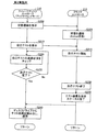
図3は、第1実施例における自己テストのタイミング制御処理の手順を示すフローチャートである。図3の例では、指示モジュール120は、ダウンタイミングモードに従って自己テストの実行タイミングを制御する。ダウンタイミングモードとは、タイミング制御処理のモード(以下「タイミングモード」とも呼ぶ)の一つである。このダウンタイミングモードでは、ディスクドライブ装置200の動作モードがActiveモードから非Activeモードに切り替えられる契機に応じて、その切り替え前に自己テストが実行される。なお、図3の例では、ディスクドライブ装置200の現行の動作モードがActiveモードであることとしている。
FIG. 3 is a flowchart showing the procedure of the self-test timing control process in the first embodiment. In the example of FIG. 3, the instruction module 120 controls the execution timing of the self test according to the down timing mode. The down timing mode is one of timing control processing modes (hereinafter also referred to as “timing mode”). In this down timing mode, a self-test is executed before the switching according to a trigger when the operation mode of the
最初のステップS100では、稼働情報取得モジュール123は、ディスクドライブ装置200の動作状態(動作モード)がActiveから非Active(例えば、IdleモードやStandbyモード)へ移行するタイミングであるか否かを判断する。この判断は、動作状態の切り替えの契機に応じて行われる。
In the first step S100, the operation information acquisition module 123 determines whether or not it is the timing when the operation state (operation mode) of the
第1実施例では、ストレージディスクコントローラ110がディスクドライブ装置200への読み書き要求を受信しない状態が所定の一定時間続くという条件が満たされたことを契機に、データ中継モジュール122は、ドライブコントローラ210に、動作モードをActiveから非Activeに切り替えるコマンド(例えば、STANDBYコマンド)を送信する。データ中継モジュール122は、ストレージディスクコントローラ110のタイマ(図示せず)を用いることによって、このような制御を行う。また、このような制御は、他のディスクドライブ装置200a、200bに対しても行われる。その結果、アクセス頻度の少ないディスクドライブ装置の動作モードが非Activeに切り替えられるので、ストレージシステム300の消費電力を低下させることが可能となる。また、ストレージシステム300全体の発熱量も小さくなるので、ディスクドライブ装置の高密度実装が可能となり、ストレージシステム300の小型化を図ることもできる。また、単位時間(例えば、1週間)あたりの動作時間(Active状態の時間)が短くなるので、ディスクドライブ装置の寿命を延ばす効果も得られる。なお、このようなストレージシステムは、MAID(Massive Array of Inactive Disk)とも呼ばれる。なお、動作モードが非Activeに切り替えられるディスクドライブ装置としては、アクセス頻度の少ないディスクドライブ装置に限らず、任意のものを採用可能である。例えば、予め選択された所定のディスクドライブ装置の動作モードが、アクセスが無い場合に非Activeに切り替えられることとしてもよい。また、このように、アクセスの無いディスクドライブ装置の中の少なくとも一部の動作モードを、読み書きの実行時の状態に近い動作モードから遠い動作モードへ(例えば、Activeモードから非Activeへ)切り替える処理を実行するダウン制御部としては、データ中継モジュール122に限らず、任意の構成を採用可能である。また、ストレージシステムの構成としては、このようなダウン制御部を有する構成に限らず、アクセスの無いディスクドライブ装置の中の少なくとも一部の動作モードが、読み書きの実行時の状態に近い動作モードから遠い動作モードへ切り替えられるような任意の構成を採用可能である。
In the first embodiment, when the condition that the
稼働情報取得モジュール123は、データ中継モジュール122の動作をモニタすることにより、データ中継モジュール122が動作モードを切り替えようとしていることを検知して、その旨を指示モジュール120に通知する。指示モジュール120は、この通知に応じて、動作モード切替コマンドの送信前に、現時点が移行タイミングであると判断する(S100:Yes)。 The operation information acquisition module 123 monitors the operation of the data relay module 122 to detect that the data relay module 122 is about to switch the operation mode, and notifies the instruction module 120 to that effect. In response to this notification, the instruction module 120 determines that the current time is the transition timing before transmitting the operation mode switching command (S100: Yes).
なお、モード制御モジュール222(図1)が自発的に動作モードをActiveから非Activeに切り替える構成を採用することもできる。この場合には、モード制御モジュール222が、動作状態を切り替える前に、切り替える旨の通知をストレージディスクコントローラ110に送信し、稼働情報取得モジュール123が、この通知を受信して、その旨を指示モジュール120に通知する。指示モジュール120は、この通知に応じてステップS100の判断を行う。この判断の後、ストレージディスクコントローラ110とドライブコントローラ210とは、図3の手順に従って、処理を進行させる。なお、動作状態の切り替えの契機としては、上述したものに限らず、任意のものを採用可能である。例えば、ユーザの指示を契機として用いてもよい。
The mode control module 222 (FIG. 1) may employ a configuration that spontaneously switches the operation mode from active to non-active. In this case, the
現時点が移行タイミングではない場合には、ステップS105で、ストレージディスクコントローラ110は、通常の処理(例えば、ホストコンピュータ400からのリードコマンドとライトコマンドとに応じた読み書き処理)を継続する。
If the current time is not the migration timing, the
現時点が移行タイミングである場合には、次のステップS110で、指示モジュール120は、ディスクドライブ装置200に自己テストの実行指示を送信する。すると、自己テストモジュール220は、指示に応じて自己テストを開始する(ステップS115)。自己テストとは、ディスクドライブ装置200自身の機能を診断する処理である。自己テスト処理としては、種々の処理を採用可能である。例えば、データの読み書きを試行する処理や、ヘッド264やスピンドルモータ(図示せず)の駆動を試行する処理を採用可能である。また、種々の機能を診断するために、自己テストは、しばしば、リード処理やライト処理の実行時と同じ動作モード(図2の例では、Activeモード)で実行される。なお、自己テストの内容は、一般的には、ベンダ(製造者)が独自に定めることができる。また、ドライブコントローラ210に対する自己テスト実行指示の形式としては、種々の形式を採用可能である。例えば、ATAで規定されているSMART EXECUTE OFF-LINE IMMEDIATEコマンドを送信する形式を採用してもよい。
If the current time is the transition timing, the instruction module 120 transmits a self-test execution instruction to the
次に、結果取得モジュール121は、自己テストの進捗状況を繰り返しチェックし(ステップS120)、自己テストの終了を待つ(ステップS125)。結果取得モジュール121は、例えば、ATAで規定されているREAD DATAコマンドをドライブコントローラ210に送信することによって、ドライブコントローラ210(自己テストモジュール220)から進捗状況を取得できる。ただし、進捗状況の取得方法としては、他の種々の方法を採用可能である。
Next, the result acquisition module 121 repeatedly checks the progress of the self test (step S120) and waits for the end of the self test (step S125). The result acquisition module 121 can acquire the progress status from the drive controller 210 (self-test module 220), for example, by transmitting a READ DATA command defined by ATA to the
自己テストモジュール220は、自己テストが終了したことに応じて(ステップS130)、次のステップS135で、テスト結果をドライブコントローラ210のメモリ218に保存し、結果取得モジュール121に送信される進捗状況を「実行中」から「完了」に切り替える。
In response to the completion of the self test (step S130), the
結果取得モジュール121は、「完了」であることを示す進捗状況を取得すると(ステップS125:Yes)、次のステップS140で、ドライブコントローラ210からテスト結果を取得し、取得したテスト結果をメモリ114に保存する。テスト結果の取得は、進捗状況の取得と同様に行われる。
When the result acquisition module 121 acquires the progress status indicating “complete” (step S125: Yes), the test result is acquired from the
ここで、正常な自己テスト結果が届かない場合(例えば、不具合のある旨のテスト結果が届いた場合や、テスト結果が届かない場合)には、結果取得モジュール121は、異常通知を行うことが好ましい。ここで、通知の相手と形式としては、任意のものを採用可能である。例えば、データ中継モジュール122に異常を通知してもよい。また、ホストコンピュータ400に異常を通知してもよい。また、ストレージシステム300に接続された管理端末のモニタ(図示せず)にエラーメッセージを表示させてもよく、管理端末のスピーカ(図示せず)に警告音を鳴らせても良い。これらは、後述する他の実施例についても同様である。
Here, when the normal self-test result does not arrive (for example, when the test result indicating that there is a defect or when the test result does not arrive), the result acquisition module 121 may notify the abnormality. preferable. Here, any notification partner and format can be adopted. For example, the data relay module 122 may be notified of the abnormality. Further, the host computer 400 may be notified of the abnormality. Further, an error message may be displayed on a monitor (not shown) of a management terminal connected to the
次のステップS145では、データ中継モジュール122は、動作状態を遷移させる指示(モード切替要求)をドライブコントローラ210に送信する。このような要求としては、例えば、STANDBYコマンドやIDLEコマンドが用いられ得る。次のステップS150では、モード制御モジュール222は、受信したモード切替要求に従って、動作モードを移行させる。
In the next step S <b> 145, the data relay module 122 transmits an instruction (mode switching request) for changing the operation state to the
なお、自己テストモジュール220が、動作モードの移行前に自己テストを実行する方法としては、任意の方法を採用可能である。例えば、データ中継モジュール122が、自己テストの完了に応じて、モード切替要求を送信することとすればよい。
It should be noted that any method can be adopted as a method for the
以後、ディスクドライブ装置200の動作モードが移行したことに応じて、ストレージディスクコントローラ110とドライブコントローラ210とは、タイミング制御処理を終了する。なお、図3のタイミング制御処理は、動作モードがActiveから非Activeに移行される毎に実行される。
Thereafter, the
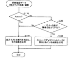
図4は、自己テストデータ(自己テスト結果)の選択処理の手順を示すフローチャートである。結果取得モジュール121は、自己テスト結果の参照要求に応じて、図4の手順に従って、提供すべき自己テスト結果を選択する。選択肢としては、新たな自己テストによる自己テスト結果と、メモリ114に格納済みの自己テスト結果と、がある。結果取得モジュール121は、ディスクドライブ装置の現時点での動作モードと、ディスクドライブ装置の動作履歴を表すパラメータ値と、に従って選択を行う。
FIG. 4 is a flowchart showing a procedure for selecting self-test data (self-test result). The result acquisition module 121 selects a self test result to be provided according to the procedure of FIG. 4 in response to a request for referring to the self test result. Options include a self test result by a new self test and a self test result stored in the
なお、自己テスト結果の参照要求としては、任意の要求を採用可能である。例えば、ストレージディスクコントローラ110が、不具合の生じる可能性が高いディスクドライブ装置を、自己テスト結果を用いて検知する処理を実行することとしてもよい。また、結果取得モジュール121が、ユーザの要求に応じて、自己テスト結果をユーザに提供することとしてもよい。例えば、結果取得モジュール121は、ストレージコントローラ100に接続された管理端末(図示せず)からユーザの指示を受信し、この管理端末のモニタ(図示せず)に、自己テスト結果を表示させてもよい。
An arbitrary request can be adopted as a reference request for the self test result. For example, the
図5は、閾値管理テーブル126の一例を示す説明図である。図5の例では、パラメータとして、「Spin-up」と、「Spin-down」と、「Power-on」と、「Power-off」と、「リード/ライト(R/W)」と、の各処理の回数と頻度とが用いられている。また、パラメータとして、連続稼働時間も用いられている。これらのパラメータは、いずれも、ディスクドライブ装置200の動作履歴を表すパラメータである。閾値管理テーブル126は、これらのパラメータの現在の値と閾値とを格納している。
FIG. 5 is an explanatory diagram showing an example of the threshold management table 126. In the example of FIG. 5, “Spin-up”, “Spin-down”, “Power-on”, “Power-off”, and “Read / Write (R / W)” are parameters. The number and frequency of each process are used. Moreover, continuous operation time is also used as a parameter. These parameters are parameters that represent the operation history of the
「Spin-up」は、ディスクドライブ装置200の動作状態を、読み書きを行う状態により近い状態に移行させる処理を意味する。「Spin-up」の例としては、ディスク262(スピンドルモータ)の回転速度を、読み書きのための所定の回転速度に上げる処理や、退避位置に退避されたヘッド264を、ディスク262上に配置する処理がある。第1実施例では、動作状態を、非Active状態からActive状態へ移行することを「Spin-up」として扱うこととしている。例えば、Spin-up回数は、ディスクドライブ装置200の電源が投入されたときと、動作状態が非Active状態からActive状態へ移行したときに、「1」増える。
“Spin-up” means a process of shifting the operation state of the
「Spin-down」は、上述した「Spin-up」とは逆の処理を意味する。「Spin-down」の例としては、ディスク262(スピンドルモータ)を停止させる処理や、ディスク262上に配置されたヘッド264を、退避位置に退避する処理がある。第1実施例では、動作状態を、Active状態から非Active状態へ移行することを「Spin-down」として扱うこととしている。
“Spin-down” means the reverse process of “Spin-up” described above. Examples of “Spin-down” include a process of stopping the disk 262 (spindle motor) and a process of retracting the
「Power-on」は、ディスクドライブ装置200の電源をONにする処理を意味する。第1実施例では、Power-on回数は、ディスクドライブ装置200の電源が投入されたときと、ディスクドライブ装置200の動作モードがSleepモードから非Sleepモード(例えば、StandbyやActive)に移行したときに、「1」増える。
“Power-on” means processing to turn on the power of the
「Power-off」は、「Power-on」とは逆の処理を意味する。第1実施例では、Power-off回数は、ディスクドライブ装置200の電源がOFFにされたときと、ディスクドライブ装置200の動作モードが非Sleepモード(例えば、ActiveやIdle)からSleepモードに移行したときに、「1」増える。
“Power-off” means the reverse of “Power-on”. In the first embodiment, the number of power-offs is the same as when the power of the
「R/W」とは、ディスクドライブ装置200に対するリードとライトとのそれぞれの処理を意味する。
“R / W” means each processing of reading and writing to the
なお、図5の閾値管理テーブル126において、「頻度」としては、現時点に至る所定の一定時間内における処理回数が用いられている。例えば、「Spin-up頻度」としては、最近の一定時間内にディスクドライブ装置200がスピンアップされた回数が用いられる。一定時間としては、種々の時間を採用可能であり、例えば、数時間から数日を採用可能である。なお、頻度のパラメータとしては、頻度に相関のある任意のパラメータを採用可能である。例えば、最後に処理を実行してからの経過時間を頻度のパラメータとして用いてもよい。
In the threshold management table 126 of FIG. 5, the “frequency” uses the number of times of processing within a predetermined fixed time until the present time. For example, as the “Spin-up frequency”, the number of times the
また、「連続稼働時間」は、ディスクドライブ装置200への電力供給が開始されてから現時点までの経過時間を意味している。単位は「分」である。
The “continuous operation time” means an elapsed time from the start of power supply to the
なお、上述した各パラメータの閾値は、予め設定された値である。また、上述した各パラメータの現在の値は、ストレージディスクコントローラ110の動作をモニタする稼働情報取得モジュール123によって、適宜更新される。
In addition, the threshold value of each parameter mentioned above is a preset value. In addition, the current value of each parameter described above is updated as appropriate by the operation information acquisition module 123 that monitors the operation of the
ところで、閾値管理テーブル126のパラメータとしては、各パラメータ毎に定められた処理が実行された回数と頻度と、連続稼働時間と、が用いられている。従って、各パラメータ値が大きいほど、近い将来にディスクドライブ装置200に不具合が生じる可能性が高いと推定される。換言すれば、各パラメータ値が大きいほど、ディスクドライブ装置200の余命が短いと推定される。そこで、結果取得モジュール121は、図4の選択処理において、各パラメータ値の大きさに応じて、提供する自己テスト結果、すなわち、自己テストを実行するか否かを選択する。
By the way, as the parameters of the threshold management table 126, the number and frequency of execution of the processing determined for each parameter and the continuous operation time are used. Therefore, it is estimated that the larger the parameter value, the higher the possibility that the
図4の最初のステップS170では、結果取得モジュール121は、ディスクドライブ装置200の動作状態が、Active状態であるか否かを判断する。指示モジュール120は、稼働情報取得モジュール123を介して、ドライブコントローラ210から、現行の動作状態を取得する。
In the first step S170 of FIG. 4, the result acquisition module 121 determines whether or not the operation state of the
動作状態がActive状態である場合には、結果取得モジュール121は、現時点が自己テストを指示すべきタイミングであると判断する。そして、次のステップS180で、結果取得モジュール121は、自己テストの実行指示をドライブコントローラ210に送信し、その自己テストの結果をドライブコントローラ210から取得する。ステップS180の処理は、図3のステップS110〜S140の処理と同様である。結果取得モジュール121は、こうして得られた自己テスト結果を採用し、選択処理を終了する。
When the operation state is the active state, the result acquisition module 121 determines that the current time is the timing for instructing the self test. In the next step S180, the result acquisition module 121 transmits a self-test execution instruction to the
動作状態がActive状態である場合には、自己テストモジュール220は、動作モードを切り替えることなく自己テストを実行できる。従って、結果取得モジュール121は、動作モードの切り替えに起因するディスクドライブ装置200の寿命の短縮を抑制しつつ、新しい自己テスト結果を得ることができる。
When the operation state is the active state, the
一方、動作状態がActive状態ではない場合には、結果取得モジュール121は、ステップS175に移行し、閾値管理テーブル126を参照して、閾値を超えているパラメータの有無を判断する。閾値を超えているパラメータがある場合には、結果取得モジュール121は、ステップS185に移行し、ディスクドライブ装置200に新たな自己テストを実行させることなく、メモリ114に保存済みの自己テスト結果を採用する。
On the other hand, when the operation state is not the active state, the result acquisition module 121 proceeds to step S175 and refers to the threshold management table 126 to determine whether there is a parameter exceeding the threshold. If there is a parameter that exceeds the threshold, the result acquisition module 121 proceeds to step S185 and adopts the self test result stored in the
閾値を超えているパラメータがある場合に、メモリ114に保存済みの自己テスト結果が採用される理由は以下の通りである。ディスクドライブ装置200の動作モードが非Activeモードである場合には、自己テストモジュール220が自己テストを実行すると、自己テストの実行に伴ってディスクドライブ装置200の動作モードが非ActiveモードからActiveモードに切り替えられる可能性がある。このような動作モードの切り替えは、ディスクドライブ装置200に対する負荷が特に高く、ディスクドライブ装置200の寿命を短縮させてしまう可能性が高い。そこで、結果取得モジュール121は、閾値を超えているパラメータがある場合には(図4:S175:Yes)、ディスクドライブ装置200に新たな自己テストを実行させることなく、メモリ114に格納済みの自己テスト結果を採用する。その結果、自己テストの実行に伴う動作モードの切り替えに起因するディスクドライブ装置200の寿命の短縮を抑えることができる。また、この場合には、自己テストの完了を待たずに迅速に自己テスト結果を提供することが可能となる。
The reason why the self-test result stored in the
なお、格納済みの結果は、動作モードが非Activeに切り替えられる直前に実行された自己テストの結果である(図3)。ここで、この自己テストの実行後には動作モードはActiveモードに切り替えられていないので、自己テストの実行時点と現時点との間のディスクドライブ装置200の劣化の度合いの差は十分に小さいと推定される。すなわち、自己テスト結果の利用時点での信頼性の低下を抑制しつつ、格納済みの自己テスト結果を、新たな自己テストの結果の代わりに利用することができる。
The stored result is a result of a self test executed immediately before the operation mode is switched to non-active (FIG. 3). Here, since the operation mode is not switched to the Active mode after the self-test is executed, it is estimated that the difference in the degree of deterioration of the
一方、閾値を超えているパラメータが無い場合には(図4:S175:No)、結果取得モジュール121は、現時点が自己テストを指示すべきタイミングであると判断し、ステップS180に移行する。ステップS180では、結果取得モジュール121は、自己テストモジュール220に自己テストを実行させ、得られた自己テスト結果を採用する。なお、モード制御モジュール222は、自己テストのために、動作モードをActiveモードに切り替える。この場合には、ディスクドライブ装置200の余命が長いと推定されるので、自己テストの実行による最新の自己テスト結果の取得が優先されている。
On the other hand, if there is no parameter exceeding the threshold (FIG. 4: S175: No), the result acquisition module 121 determines that the current time is the timing for instructing the self test, and the process proceeds to step S180. In step S180, the result acquisition module 121 causes the
以上説明したように、ダウンタイミングモード(図3)では、指示モジュール120は、ディスクドライブ装置200の動作モードがActiveモードから非Activeモードに切り替えられる契機、すなわち、スピンダウンの契機に応じて、動作モードの切り替え前に、自己テストモジュール220に自己テストを実行させる。この自己テストの結果は、次に動作モードが非ActiveモードからActiveモードに切り替えられるまでの間は、すなわち、次のスピンアップまでの間は、現時点でのディスクドライブ装置200の状態を表すものとして、利用することが可能である。その結果、自己テストの結果の利用時点での信頼性と、自己テストに起因するディスクドライブ装置の寿命の短縮抑制と、のバランスをとることができる。
As described above, in the down timing mode (FIG. 3), the instruction module 120 operates in response to the trigger for switching the operation mode of the
また、第1実施例では、図4に示すように、結果取得モジュール121は、テスト結果の参照要求に応じて、ディスクドライブ装置200の動作モードとパラメータとに基づいて自己テストを実行するか否かを選択する。従って、自己テストの結果の利用時点での信頼性と、自己テストに起因するディスクドライブ装置の寿命の短縮抑制と、のバランスをとることができる。なお、ステップS175における、自己テストを実行すると判断するための条件としては、近い将来の不具合の可能性が比較的低いことを示す任意の条件を採用可能である。例えば、パラメータとして、図5に示すパラメータの任意の一部のみを用いることとしてもよい。
In the first embodiment, as shown in FIG. 4, the result acquisition module 121 determines whether or not to execute a self test based on the operation mode and parameters of the
B.第2実施例:
図6は、第2実施例におけるタイミング制御処理の手順を示すフローチャートである。図3に示す第1実施例との差違は、指示モジュール120が、ダウンタイミングモードの代わりに、アップタイミングモードに従ってタイミング制御処理を実行する点である。アップタイミングモードでは、ディスクドライブ装置200の動作モードが非ActiveモードからActiveモードに切り替えられたことに応じて、自己テストが実行される。データ処理システムの構成は、図1に示すデータ処理システム10と同じである。
B. Second embodiment:
FIG. 6 is a flowchart showing a procedure of timing control processing in the second embodiment. The difference from the first embodiment shown in FIG. 3 is that the instruction module 120 executes the timing control process according to the up timing mode instead of the down timing mode. In the up timing mode, a self test is executed in response to the operation mode of the
最初のステップS200では、データ中継モジュール122(図1)が、動作モードを非ActiveモードからActiveモードに遷移させる指示(モード切替要求)をドライブコントローラ210に送信する。第2実施例では、ディスクドライブ装置200の動作モードが非Activeモードである状態でストレージディスクコントローラ110がディスクドライブ装置200に対する読み書き要求を受信したことを契機に、データ中継モジュール122は、ドライブコントローラ210に、動作モードを非ActiveからActiveに切り替えるコマンドを送信する。
In the first step S200, the data relay module 122 (FIG. 1) transmits an instruction (mode switching request) for changing the operation mode from the non-active mode to the active mode to the
なお、動作モードの切り替えの契機としては、任意のものを採用可能である。例えば、ユーザの指示を契機として用いてもよい。 Note that any operation mode can be used as a trigger. For example, a user instruction may be used as a trigger.
次のステップS205では、モード制御モジュール222は、受信したモード切替要求に従って、動作モードを移行させる。
In the next step S205, the
稼働情報取得モジュール123は、ストレージディスクコントローラ110(データ中継モジュール122)の動作をモニタすることにより、データ中継モジュール122がモード切替要求を送信したことを検知して、その旨を指示モジュール120に通知する。指示モジュール120は、この通知に応じて、自己テストの実行指示をドライブコントローラ210に送信し、結果取得モジュール121は、その自己テストの結果をドライブコントローラ210から取得する(S210〜S240)。これらのステップS210〜S240の処理は、図3のステップS110〜S140の処理と、それぞれ同様である。結果取得モジュール121が自己テスト結果をメモリ114に保存したことに応じて、タイミング制御処理は終了する。図6に示すタイミング制御処理は、動作モードが非ActiveからActiveに移行される毎に実行される。
The operation information acquisition module 123 monitors the operation of the storage disk controller 110 (data relay module 122), detects that the data relay module 122 has transmitted a mode switching request, and notifies the instruction module 120 accordingly. To do. In response to this notification, the instruction module 120 transmits a self-test execution instruction to the
なお、自己テストの実行は、動作モードのActiveモードへの移行後の、読み書き処理の実行前に、行われることが好ましい。こうすれば、ディスクドライブ装置200に不具合のある状態で読み書き処理が実行されることを抑制できる。このようなタイミングで自己テストを実行する方法としては、任意の方法を採用可能である。例えば、データ中継モジュール122が、自己テストの完了に応じて、読み書き処理を実行することとすればよい。
The self test is preferably performed before the read / write process is performed after the operation mode is shifted to the Active mode. In this way, it is possible to prevent the read / write process from being executed in a state where the
ところで、結果取得モジュール121は、第1実施例と同様に、自己テスト結果の参照要求に応じて、図4の手順に従って、提供すべき自己テスト結果を選択する。ここで、ステップS185では、メモリ114に格納済みの自己テスト結果が用いられる。この格納済みの自己テスト結果は、最後に動作モードが非ActiveモードからActiveモードに切り替えられたときに実行された自己テストの結果である。ここで、この自己テストの実行後には動作モードはActiveモードに切り替えられていないので、自己テストの実行時点と現時点との間のディスクドライブ装置200の状態の差は十分に小さいと推定される。従って、自己テスト結果の利用時点での信頼性の低下を抑制しつつ、格納済みの自己テスト結果を、現時点でのディスクドライブ装置200の状態を表すものとして、利用することが可能である。
By the way, the result acquisition module 121 selects the self-test result to be provided according to the procedure of FIG. 4 according to the reference request for the self-test result, as in the first embodiment. Here, in step S185, the self test result stored in the
以上のように、アップタイミングモード(図6)では、指示モジュール120は、ディスクドライブ装置200の動作モードが非ActiveモードからActiveモードに切り替えられる契機、すなわち、スピンアップの契機に応じて、動作モードの切り替え後に、自己テストモジュール220に自己テスト実行の指示を送信する。従って、図4のステップS185では、結果取得モジュール121は、ドライブコントローラ210に自己テストを実行させることなく、適切な自己テスト結果を利用することができる。その結果、自己テストの結果の利用時点での信頼性と、自己テストに起因するディスクドライブ装置の寿命の短縮抑制と、のバランスをとることができる。
As described above, in the up-timing mode (FIG. 6), the instruction module 120 determines the operation mode according to the timing when the operation mode of the
C.第3実施例:
図7は、第3実施例におけるタイミングモードを選択する処理の手順を示すフローチャートである。上述の第1と第2の実施例との差違は、指示モジュール120が、タイミングモードとして、一定間隔モードとアクセスタイミングモードとの2つのモードを有している点である。データ処理システムの構成は、図1に示すデータ処理システム10と同じである。
C. Third embodiment:
FIG. 7 is a flowchart showing a processing procedure for selecting a timing mode in the third embodiment. The difference between the first and second embodiments described above is that the instruction module 120 has two modes, a fixed interval mode and an access timing mode, as timing modes. The configuration of the data processing system is the same as that of the
一定間隔モードでは、指示モジュール120は、所定の一定時間間隔毎にドライブコントローラ210に自己テストを実行させる。アクセスタイミングモードでは、指示モジュール120は、ディスクドライブ装置へのアクセス状況に応じて、自己テストを実行させるか否かを決定する。このように、2つのタイミングモード間では、自己テストの実行タイミング(チェックタイミング)が互いに異なっている。なお、各モードの詳細については後述する。また、以下、ディスクドライブ装置200が対象であることとして説明する。ただし、他のディスクドライブ装置200a、200bを対象とする場合についても処理内容は同様である。
In the regular interval mode, the instruction module 120 causes the
指示モジュール120は、図7の手順に従って、タイミングモードを選択する。この選択処理は、自己テスト結果の参照要求の有無に拘わらずに実行される。選択処理を実行するタイミングとしては、任意のタイミングを採用可能である。例えば、指示モジュール120が、所定の一定時間毎に選択処理を実行することとしてもよい。また、ユーザの指示を契機として用いてもよい。なお、第3実施例では、指示モジュール120は、タイミングモードの初期値として一定間隔モードを採用する。ただし、他のモードを初期値として採用してもよい。 The instruction module 120 selects a timing mode according to the procedure of FIG. This selection process is executed regardless of whether or not a self-test result reference request is present. Arbitrary timings can be adopted as the timing for executing the selection process. For example, the instruction module 120 may execute the selection process at predetermined time intervals. Moreover, you may use a user's instruction | indication as a trigger. In the third embodiment, the instruction module 120 adopts the constant interval mode as the initial value of the timing mode. However, other modes may be adopted as initial values.
最初のステップS300、S304では、指示モジュール120は、現行のタイミングモードを確認し、アクセスタイミングモードであるか否かを判断する。現行のタイミングモードがアクセスタイミングモードである場合には、指示モジュール120は、選択処理を終了する。 In first steps S300 and S304, the instruction module 120 confirms the current timing mode and determines whether or not it is the access timing mode. If the current timing mode is the access timing mode, the instruction module 120 ends the selection process.
現行のタイミングモードがアクセスタイミングモードではない場合、すなわち、一定間隔モードである場合には、次のステップS308で、指示モジュール120は、閾値管理テーブル126(図5)を参照して、閾値を超えているパラメータの有無を判断する。 If the current timing mode is not the access timing mode, that is, if it is the constant interval mode, the instruction module 120 refers to the threshold management table 126 (FIG. 5) and exceeds the threshold in the next step S308. Determine whether there are any parameters.
閾値を超えているパラメータがない場合には、指示モジュール120は、ステップS312に移行し、一定間隔モードを選択(維持)して、選択処理を終了する。 If there is no parameter exceeding the threshold value, the instruction module 120 proceeds to step S312, selects (maintains) the constant interval mode, and ends the selection process.
閾値を超えているパラメータがある場合には、指示モジュール120は、ステップS316に移行し、アクセスタイミングモードを選択して、選択処理を終了する。 If there is a parameter that exceeds the threshold, the instruction module 120 proceeds to step S316, selects an access timing mode, and ends the selection process.
指示モジュール120は、タイミングモードの選択の契機がある毎に、上述の選択処理を実行する。 The instruction module 120 executes the above selection process every time the timing mode is selected.
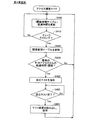
図8は、一定間隔モードにおけるタイミング制御処理の手順を示すフローチャートである。このタイミング制御処理は、自己テスト結果の参照要求の有無に拘わらずに実行される。最初のステップS350では、指示モジュール120は、チェック間隔設定テーブル128(図1)を参照することによって、現時点が自己テストの実行タイミングであるか否かを判断する。図9は、チェック間隔設定テーブル128の一例を示す説明図である。閾値は、ディスクドライブ装置の状態のチェック(自己テスト)を行う時間間隔を意味している。図9の例では、予め1440分(24時間)に設定されている。ただし、これとは異なる値に設定されていてもよい。現在の値は、最後の自己テストの実行時点から現時点までの経過時間である。以下、この現在の値(チェック間隔の現在の値)のことを「チェック経過時間」とも呼ぶ。指示モジュール120は、ストレージディスクコントローラ110のタイマ(図示せず)を用いることによって、このチェック経過時間を更新する。
FIG. 8 is a flowchart showing a procedure of timing control processing in the constant interval mode. This timing control process is executed regardless of whether or not a self-test result reference request is present. In the first step S350, the instruction module 120 refers to the check interval setting table 128 (FIG. 1) to determine whether or not the current time is the self test execution timing. FIG. 9 is an explanatory diagram showing an example of the check interval setting table 128. The threshold means a time interval for checking the state of the disk drive device (self-test). In the example of FIG. 9, it is set in advance to 1440 minutes (24 hours). However, it may be set to a value different from this. The current value is the elapsed time from the time of the last self test execution to the present time. Hereinafter, this current value (the current value of the check interval) is also referred to as “check elapsed time”. The instruction module 120 updates this check elapsed time by using a timer (not shown) of the
チェック経過時間が閾値以下である場合には、指示モジュール120は、実行タイミングではないと判断し、チェック経過時間が閾値を超えることを待つ。 When the check elapsed time is equal to or less than the threshold, the instruction module 120 determines that it is not the execution timing, and waits for the check elapsed time to exceed the threshold.
チェック経過時間が閾値を超えている場合には、指示モジュール120は、自己テストの実行指示をドライブコントローラ210に送信し、結果取得モジュール121は、その自己テストの結果をドライブコントローラ210から取得する(S355〜S365)。これらのステップS355、S360、S365のそれぞれの処理は、図3のステップS110、S120−S125、S140のそれぞれの処理と同じである(ステップS360の処理は、ステップS120、S125の処理と同じである)。なお、一定間隔モードでは、自己テストは、ディスクドライブ装置200の現行の動作モードに拘わらずに実行される。
When the check elapsed time exceeds the threshold value, the instruction module 120 transmits a self-test execution instruction to the
指示モジュール120は、自己テスト結果が読み出されてメモリ114に保存されたことに応じて、チェック経過時間をゼロにリセットし、次の実行タイミングを待つ。なお、チェック経過時間のリセットのタイミングとしては、自己テストの実行に応じて定まる任意のタイミングを採用可能である。例えば、図8のステップS355でチェック経過時間がリセットされることとしてもよい。これは、後述する他の実施例についても同様である。
The instruction module 120 resets the check elapsed time to zero in response to the self-test result being read and stored in the
図10は、アクセスタイミングモードにおけるタイミング制御処理の手順を示すフローチャートである。図8に示す一定間隔モードとの差違は、チェック経過時間が閾値を超えている場合に、指示モジュール120が、さらに、ディスクドライブ装置200に対する読み書き要求を待って、ドライブコントローラ210に自己テストを実行させる点である。具体的には、ステップS350とステップS355との間に、読み書き要求を待つステップS352が設けられている。また、ステップS365の後に、読み書き要求に応じた読み書き処理を実行するステップS370が設けられている。他のステップS350、S355、S360、S365の処理は、図8の例と同じである。
FIG. 10 is a flowchart illustrating a procedure of timing control processing in the access timing mode. The difference from the constant interval mode shown in FIG. 8 is that when the check elapsed time exceeds the threshold, the instruction module 120 further waits for a read / write request to the
チェック経過時間が閾値を超えている場合には(ステップS350:Yes)、指示モジュール120は、ステップS352に移行する。ステップS352では、稼働情報取得モジュール123は、データ中継モジュール122の動作をモニタすることにより、データ中継モジュール122(コントローラ110)がリードコマンドやライトコマンドを受信したことを検知して、その旨を指示モジュール120に通知する。指示モジュール120は、この通知に応じて、現時点が自己テストを指示すべきタイミングであると判断し、ステップS355に移行して、自己テストの実行指示をドライブコントローラ210に送信する。そして、結果取得モジュール121は、その自己テストの結果をドライブコントローラ210から取得して、メモリ114に保存する(S360、S365)。これらのステップS355、S360、S365の処理は、データ中継モジュール122がホストコンピュータ400からのリードコマンドやライトコマンドに応じたリード処理やライト処理を実行する前に、実行される。
When the check elapsed time exceeds the threshold (step S350: Yes), the instruction module 120 proceeds to step S352. In step S352, the operation information acquisition module 123 monitors the operation of the data relay module 122, detects that the data relay module 122 (controller 110) has received a read command or a write command, and gives an instruction to that effect. Notify the module 120. In response to this notification, the instruction module 120 determines that the current time is the timing for instructing the self test, moves to step S355, and transmits a self test execution instruction to the
自己テストの完了に応じて、次のステップS370で、データ中継モジュール122は、ディスクドライブ装置200にリードコマンドやライトコマンドを送信する。送信されるコマンドは、ホストコンピュータ400の要求に応じたものである。
In response to the completion of the self test, the data relay module 122 transmits a read command and a write command to the
以上のようにして、自己テスト結果がメモリ114に保存される。この自己テスト結果は、図4と同じ手順に従って利用される。
As described above, the self test result is stored in the
以上のように、アクセスタイミングモードでは、指示モジュール120は、ディスクドライブ装置200に対する読み書き要求に同期して、自己テストモジュール220に自己テストを実行させる。従って、アクセスタイミングモードでは、自己テスト実行のみのためにディスクドライブ装置200の動作モードが非ActiveモードからActiveモードに切り替えられることが抑制される。その結果、自己テストの実行に起因するディスクドライブ装置200の寿命の短縮を抑えることができる。
As described above, in the access timing mode, the instruction module 120 causes the
また、第3実施例では、指示モジュール120は、ディスクドライブ装置200の動作履歴を表すパラメータに基づいて自己テスト実行のタイミングを切り替えている(図7)。具体的には、指示モジュール120は、パラメータに基づいて、近い将来にディスクドライブ装置200に不具合が生じる可能性の高さを判断する。そして、指示モジュール120は、可能性が比較的高いと判断した場合には、アクセスタイミングモードを選択し、可能性が比較的低いと判断した場合には、一定間隔モードを選択する。その結果、自己テストの結果の利用時点での信頼性と、自己テストに起因するディスクドライブ装置の寿命の短縮抑制と、のバランスをとることができる。
In the third embodiment, the instruction module 120 switches the self test execution timing based on a parameter representing the operation history of the disk drive device 200 (FIG. 7). Specifically, the instruction module 120 determines the high possibility that a failure will occur in the
なお、図7のステップS308における、アクセスタイミングモードを選択するための条件としては、近い将来の不具合の可能性が比較的高いことを示す任意の条件を採用可能である。例えば、パラメータとして、図5に示すパラメータの任意の一部のみを用いることとしてもよい。 Note that as the condition for selecting the access timing mode in step S308 in FIG. 7, any condition indicating that the possibility of a failure in the near future is relatively high can be employed. For example, only a part of the parameters shown in FIG. 5 may be used as the parameters.
また、アクセスタイミングモードの代わりに用いられるタイミングモードとしては、一定間隔モードに限らず、任意のタイミングモードを利用可能である。ただし、ディスクドライブ装置200の動作状況と動作履歴とに拘わらずに自己テストの実行を指示するモードを採用することが好ましい。こうすれば、自己テスト結果の利用時点での信頼性を高めることができる。例えば、所定のスケジュールに従って自己テストの実行を指示するモードを採用してもよい。ただし、一定間隔モードを採用すれば、定期的にテスト結果が更新されるので、テスト結果の利用時点での信頼性を効果的に高めることができる。
Further, the timing mode used instead of the access timing mode is not limited to the constant interval mode, and any timing mode can be used. However, it is preferable to adopt a mode instructing execution of a self test regardless of the operation status and operation history of the
D.第4実施例:
図11は、タイミング制御処理の別の例の手順を示すフローチャートである。図8に示す一定間隔モードとの差違は、このアクセス頻度モードでは、チェック経過時間が閾値を超えている場合に、さらに、指示モジュール120が、ディスクドライブ装置への現時点でのアクセス頻度に応じて、自己テストを実行するか否かを判断する点である。なお、このタイミング制御処理は、自己テスト結果の参照要求の有無に拘わらずに実行される。また、以下、ディスクドライブ装置200が対象であることとして説明する。ただし、他のディスクドライブ装置200a、200bを対象とする場合についても処理内容は同様である。
D. Fourth embodiment:
FIG. 11 is a flowchart illustrating the procedure of another example of the timing control process. The difference from the constant interval mode shown in FIG. 8 is that, in this access frequency mode, when the check elapsed time exceeds the threshold, the instruction module 120 further responds to the current access frequency to the disk drive device. The point is to determine whether or not to execute a self-test. This timing control process is executed regardless of whether there is a request for referring to the self-test result. In the following description, it is assumed that the
最初のステップS400では、稼働情報取得モジュール123が、データ中継モジュール122の動作をモニタすることにより、閾値管理テーブル126の「R/W頻度」の現在の値を更新する。第4実施例では、「R/W頻度」として、最後のディスクドライブ装置200に対するリード処理あるいはライト処理の実行時点からの経過時間を採用している。以下、R/W頻度の現在の値を「アクセス経過時間」とも呼ぶ。
In the first step S400, the operation information acquisition module 123 updates the current value of “R / W frequency” in the threshold management table 126 by monitoring the operation of the data relay module 122. In the fourth embodiment, as the “R / W frequency”, an elapsed time from the execution time of the read process or the write process with respect to the last
次のステップS410では、指示モジュール120は、チェック間隔設定テーブル128(図9)を参照することによって、チェック経過時間が閾値以下であるか否かを判断する。このステップS410の処理は、図8のステップS350の処理と同じである。 In the next step S410, the instruction module 120 refers to the check interval setting table 128 (FIG. 9) to determine whether or not the check elapsed time is equal to or less than a threshold value. The processing in step S410 is the same as the processing in step S350 in FIG.
チェック経過時間が閾値以下である場合には(S410:No)、指示モジュール120は、実行タイミングではないと判断し、チェック経過時間が閾値を超えることを待つ。この間も、稼働情報取得モジュール123は、適切に、アクセス経過時間(「R/W頻度」の現在の値)を更新する。 When the check elapsed time is equal to or less than the threshold (S410: No), the instruction module 120 determines that it is not the execution timing, and waits for the check elapsed time to exceed the threshold. During this time, the operation information acquisition module 123 appropriately updates the access elapsed time (current value of “R / W frequency”).
チェック経過時間が閾値を超えている場合には(S410:Yes)、指示モジュール120は、ステップS420で閾値管理テーブル126(図5)を参照し、ステップS430で、アクセス経過時間が閾値を超えているか否かを判断する。ここで、アクセス経過時間が閾値を超えていることは、アクセスの頻度が閾値で表される頻度未満であることを意味している。 If the check elapsed time exceeds the threshold (S410: Yes), the instruction module 120 refers to the threshold management table 126 (FIG. 5) in step S420, and the access elapsed time exceeds the threshold in step S430. Determine whether or not. Here, that the access elapsed time exceeds the threshold means that the access frequency is less than the frequency represented by the threshold.
アクセス経過時間が閾値を超えていない場合には、指示モジュール120は、ディスクドライブ装置200に新たな自己テストを実行させることなく、チェック経過時間をゼロにリセットし、次の実行タイミングを待つ。
If the access elapsed time does not exceed the threshold, the instruction module 120 resets the check elapsed time to zero without waiting for the next execution timing without causing the
アクセス経過時間が閾値を超えている場合には、指示モジュール120は、現時点が自己テストを指示すべきタイミングであると判断して、自己テストの実行指示をドライブコントローラ210に送信する。結果取得モジュール121は、その自己テストの結果をドライブコントローラ210から取得する(S455〜S465)。これらのステップS455、S460、S465の処理は、図8のステップS355、S360、S365の処理と、それぞれ同じである。指示モジュール120は、自己テスト結果が読み出されてメモリ114に保存された後、チェック経過時間をゼロにリセットし、次の実行タイミングを待つ。
If the access elapsed time exceeds the threshold value, the instruction module 120 determines that the current time is the timing for instructing the self test, and transmits a self test execution instruction to the
このように、自己テスト結果がメモリ114に保存される。この自己テスト結果は、図4と同じ手順に従って利用される。
In this way, the self test result is stored in the
以上のように、アクセス頻度モードでは、指示モジュール120は、現時点でのアクセス経過時間が閾値以下である場合、すなわち、現時点でのアクセス頻度が閾値によって表される頻度よりも高い場合には、ディスクドライブ装置200に自己テストを実行させない。この理由は、以下の通りである。現時点でのアクセス頻度が高いことは、ディスクドライブ装置200が頻繁な読み書き要求に応じて正常に動作していることを意味している。従って、近い将来にディスクドライブ装置200に不具合が生じる可能性の現時点までの変化は十分に小さいと推定される。換言すれば、格納済みの自己テスト結果を取得した時点と現時点との間のディスクドライブ装置200の劣化の度合いの差は十分に小さいと推定される。そこで、アクセス頻度モードでは、現時点でのアクセス頻度が比較的高い場合には自己テストは実行されず、格納済みの自己テスト結果が引き続き利用される。この場合でも、上述したように、自己テスト結果の利用時点での信頼性の低下が抑制される。また、自己テストの実行に起因するディスクドライブ装置200の寿命の短縮を抑えることができる。
As described above, in the access frequency mode, the instruction module 120 determines whether the current access elapsed time is less than or equal to the threshold, that is, if the current access frequency is higher than the frequency represented by the threshold. The
なお、アクセス頻度モードに従った処理の実施形態としては、種々の形態を採用可能である。例えば、指示モジュール120が、アクセス頻度モードに従った処理を継続することとしてもよい。この代わりに、図7に示す手順において、アクセスタイミングモードの代わりにアクセス頻度モードを用いることとしてもよい。 Various forms of processing according to the access frequency mode can be adopted. For example, the instruction module 120 may continue processing according to the access frequency mode. Instead, in the procedure shown in FIG. 7, an access frequency mode may be used instead of the access timing mode.
E.第5実施例:
図12は、タイミング制御処理の別の例の手順を示すフローチャートである。図8に示す一定間隔モードとの差違は、この状況判定モードでは、チェック経過時間が閾値を超えている場合に、さらに、指示モジュール120が、ディスクドライブ装置の動作状態と、スピンアップとスピンダウンとのそれぞれの回数と、に応じて、自己テスト実行のタイミングを切り替える点である。なお、このタイミング制御処理は、自己テスト結果の参照要求の有無に拘わらずに実行される。また、以下、ディスクドライブ装置200が対象であることとして説明する。ただし、他のディスクドライブ装置200a、200bを対象とする場合についても処理内容は同様である。
E. Example 5:
FIG. 12 is a flowchart illustrating a procedure of another example of the timing control process. The difference from the constant interval mode shown in FIG. 8 is that, in this situation determination mode, when the check elapsed time exceeds a threshold value, the instruction module 120 further determines the operation status of the disk drive device, spin-up and spin-down. The timing of self-test execution is switched in accordance with the number of times. This timing control process is executed regardless of whether there is a request for referring to the self-test result. In the following description, it is assumed that the
最初のステップS500では、指示モジュール120は、チェック間隔設定テーブル128(図9)を参照することによって、チェック経過時間が閾値以下であるか否かを判断する。このステップS500の処理は、図8のステップS350の処理と同じである。 In the first step S500, the instruction module 120 determines whether or not the check elapsed time is equal to or less than the threshold by referring to the check interval setting table 128 (FIG. 9). The processing in step S500 is the same as the processing in step S350 in FIG.
次のステップS510では、指示モジュール120は、稼働情報取得モジュール123を介して、ディスクドライブ装置200の動作モードが非Activeモードであるか否かを判断する。
In the next step S510, the instruction module 120 determines whether the operation mode of the
動作モードがActiveモードである場合には、指示モジュール120は、現時点が自己テストを指示すべきタイミングであると判断して、自己テストの実行指示をドライブコントローラ210に送信する(S555)。結果取得モジュール121は、その自己テストの結果をドライブコントローラ210から取得する(S560〜S565)。これらのステップS555、S560、S565の処理は、図8のステップS355、S360、S365の処理と、それぞれ同様である。指示モジュール120は、自己テスト結果が読み出されてメモリ114に保存された後、チェック経過時間をゼロにリセットして、次の実行タイミングを待つ。
When the operation mode is the active mode, the instruction module 120 determines that the current time is the timing for instructing the self test, and transmits an instruction to execute the self test to the drive controller 210 (S555). The result acquisition module 121 acquires the result of the self test from the drive controller 210 (S560 to S565). The processes in steps S555, S560, and S565 are the same as the processes in steps S355, S360, and S365 in FIG. The instruction module 120 reads the self test result and saves it in the
動作モードが非Activeモードである場合(Activeモードでない場合)には、指示モジュール120は、ステップS520に移行する。このステップS520では、指示モジュール120は、図4のS175や図7のS308と同様に、近い将来にディスクドライブ装置200に不具合が生じる可能性の高さを判断する。具体的には、指示モジュール120は、「Spin-up回数」と「Spin-down回数」とのそれぞれが、それぞれの閾値に基づく基準値以上か否かを判断する。ここで、基準値としては、閾値よりも小さい種々の値を採用可能である。例えば、閾値よりも所定値(例えば「1」)だけ小さい値を採用可能である。判断の基準値として閾値よりも小さい値が用いられる理由については後述する。
If the operation mode is the non-active mode (not the active mode), the instruction module 120 proceeds to step S520. In this step S520, the instruction module 120 determines the possibility that a problem will occur in the
「Spin-up回数」と「Spin-down回数」と両方が、それぞれの判断基準値よりも小さい場合には、指示モジュール120が、現時点が自己テストを指示すべきタイミングであると判断する。そして、指示モジュール120と結果取得モジュール121とは、ステップS555、S560、S565の処理を実行することによって、新たな自己テストによる自己テスト結果をメモリ114に格納する。
If both “Spin-up count” and “Spin-down count” are smaller than the respective judgment reference values, the instruction module 120 determines that the current time is the timing at which the self-test should be instructed. Then, the instruction module 120 and the result acquisition module 121 store the self test results of the new self test in the
「Spin-up回数」と「Spin-down回数」との少なくとも一方が、それぞれの判断基準値以上である場合には、指示モジュール120は、ステップS530に移行する。このステップS530の処理は、図10のステップS352の処理と同じである。ストレージディスクコントローラ110がリードコマンドやライトコマンドを受信したことに応じて、指示モジュール120は、現時点が自己テストを指示すべきタイミングであると判断する。そして、指示モジュール120は、ステップS555に移行し、自己テストの実行指示をドライブコントローラ210に送信する。そして、結果取得モジュール121は、その自己テストの結果をドライブコントローラ210から取得して、メモリ114に保存する(S560、S565)。これらのステップS555、S560、S565の処理は、図10の例と同様に、データ中継モジュール122がホストコンピュータ400からのリードコマンドやライトコマンドに応じたリード処理やライト処理を実行する前に、実行される。また、この場合には、データ中継モジュール122は、自己テストの完了に応じて、リード処理やライト処理を実行する(図示省略)。なお、データ中継モジュール122によるリード処理やライト処理の実行タイミングとしては、自己テストの完了後の任意のタイミングを採用可能である。例えば、ステップS560とステップS565との間でもよく、ステップS565の後でもよい。
If at least one of the “Spin-up count” and the “Spin-down count” is equal to or greater than each determination reference value, the instruction module 120 proceeds to Step S530. The processing in step S530 is the same as the processing in step S352 in FIG. In response to the
以上のようにして、自己テスト結果がメモリ114に保存される。この自己テスト結果は、図4と同じ手順に従って利用される。
As described above, the self test result is stored in the
以上のように、状況判定モードでは、指示モジュール120は、ディスクドライブ装置200の現行の動作モードと、ディスクドライブ装置200の動作履歴を表すパラメータと、の両方に基づいて自己テスト実行のタイミングを切り替えている。具体的には、動作モードがActiveモードである場合には、チェック経過時間で決まるタイミングで自己テストが実行される。この場合には、図4のステップS170、S180と同様に、動作モードの切り替えに起因するディスクドライブ装置200の寿命の短縮を抑制しつつ、新しい自己テスト結果が取得される。
As described above, in the situation determination mode, the instruction module 120 switches the timing of self-test execution based on both the current operation mode of the
また、現行の動作モードが非Activeモードであっても、「Spin-up回数」と「Spin-down回数」と両方が、それぞれの判断基準値よりも小さい場合には、チェック経過時間で決まるタイミングで自己テストが実行される。この場合には、ディスクドライブ装置200の余命が長いと推定されるので、自己テストの実行による最新の自己テスト結果の取得が優先されている。
In addition, even if the current operation mode is the non-active mode, if both “Spin-up count” and “Spin-down count” are smaller than the respective criterion values, the timing determined by the check elapsed time A self-test is performed. In this case, since the life expectancy of the
一方、現行の動作モードが非Activeモードであり、かつ、「Spin-up回数」と「Spin-down回数」との少なくとも一方が、それぞれの判断基準値以上である場合には、ディスクドライブ装置200に対する読み書き要求に同期して、自己テストが実行される。従って、この場合には、自己テスト実行のみのために動作モードが非ActiveモードからActiveモードに切り替えられることが抑制される。その結果、自己テストの実行に伴う動作モードの切り替えに起因するディスクドライブ装置200の寿命の短縮を抑えることができる。
On the other hand, when the current operation mode is the non-active mode and at least one of the “spin-up count” and the “spin-down count” is equal to or more than the respective determination reference values, the disk drive device 200 A self-test is executed in synchronization with the read / write request for. Therefore, in this case, switching the operation mode from the non-active mode to the active mode only for the self test execution is suppressed. As a result, it is possible to suppress the shortening of the life of the
なお、ステップS520の判断で用いるパラメータとしては、「Spin-up回数」と「Spin-down回数」とに限らず、他の種々のパラメータを採用可能である。例えば、図5に示す閾値管理テーブル126の全てのパラメータに関して、それぞれの判断基準値以上のパラメータが有る場合に、指示モジュール120がステップS530に移行することとしてもよい。なお、判断基準値として閾値よりも小さい値が用いられるのは、パラメータ値が自己テストの実行によって閾値を超えてしまうことを抑制するためである。ただし、判断基準値として閾値をそのまま用いてもよい。また、ステップS520における、読み書き要求の有無に拘わらずに自己テストを指示するための条件としては、近い将来の不具合の可能性が比較的低いことを示す任意の条件を採用可能である。 Note that the parameters used in the determination in step S520 are not limited to “Spin-up count” and “Spin-down count”, and various other parameters can be adopted. For example, regarding all the parameters in the threshold management table 126 shown in FIG. 5, the instruction module 120 may move to step S530 when there are parameters equal to or greater than the respective determination reference values. The reason why the value smaller than the threshold is used as the determination reference value is to prevent the parameter value from exceeding the threshold due to the execution of the self test. However, the threshold value may be used as it is as the determination reference value. In addition, as a condition for instructing the self-test regardless of the presence / absence of the read / write request in step S520, any condition indicating that the possibility of a failure in the near future is relatively low can be adopted.
また、状況判定モードに従った処理の実施形態としては、種々の形態を採用可能である。例えば、指示モジュール120が、状況判定モードに従った処理を継続することとしてもよい。この代わりに、図7に示す手順において、アクセスタイミングモードの代わりに状況判定モードを用いることとしてもよい。 Moreover, various forms can be adopted as embodiments of processing according to the situation determination mode. For example, the instruction module 120 may continue processing according to the situation determination mode. Instead, the situation determination mode may be used instead of the access timing mode in the procedure shown in FIG.
また、ステップS510とS520の間に、指示モジュール120が、ディスクドライブ装置200が非Active状態となる直前に自己テストが実行されたか否かを判断することとしてもよい。ここで、このような自己テストの結果が結果取得モジュール121によって取得されている場合には、指示モジュール120は、自己テスト指示をせずに、チェック経過時間をゼロにリセットして、次の実行タイミングを待つこととしてもよい。こうすれば、自己テストの実行に起因するディスクドライブ装置200の寿命の短縮を抑制できる。
Also, between steps S510 and S520, the instruction module 120 may determine whether or not a self-test has been executed immediately before the
F.第6実施例:
F1.装置構成:
図13は、第6実施例におけるストレージシステム300fの構成を示す説明図である。図1に示すストレージシステム300との差違は、タイミング制御処理、すなわち、自己テストの実行タイミングの決定が、ストレージディスクコントローラ110の代わりに、ドライブコントローラ210の指示モジュール120fによって行われる点である。そのために、ストレージシステム300fでは、指示モジュール120fと、稼働情報取得モジュール123fと、閾値管理テーブル126と、チェック間隔設定テーブル128とが、ストレージディスクコントローラ110の代わりに、ドライブコントローラ210のメモリ218に格納されている。他の構成は、図1のストレージシステム300と同じである。
F. Example 6:
F1. Device configuration:
FIG. 13 is an explanatory diagram showing the configuration of the
なお、図13では、ストレージコントローラ100の構成要素として、ストレージディスクコントローラ110のメモリ114と、結果取得モジュール121fと、のみが示されており、他の構成要素は図示が省略されている。また、ディスクドライブ装置200の構成要素として、ドライブコントローラ210のメモリ218と、指示モジュール120fと、稼働情報取得モジュール123fと、閾値管理テーブル126と、チェック間隔設定テーブル128と、自己テストモジュール220fと、のみが示されており、他の構成要素は図示が省略されている。なお、図13には示されていない他のディスクドライブ装置200a、200b(図1)の構成も、図13のディスクドライブ装置200と同じである。
In FIG. 13, only the
F2.タイミング制御処理:
図14は、第6実施例におけるタイミング制御処理の手順を示すフローチャートである。図14の例では、指示モジュール120fは、図8と同様の一定間隔モードに従ってタイミング制御処理を実行する。このタイミング制御処理は、自己テスト結果の参照要求の有無に拘わらずに実行される。また、以下、ディスクドライブ装置200が対象であることとして説明する。ただし、他のディスクドライブ装置200a、200bを対象とする場合についても処理内容は同様である。
F2. Timing control processing:
FIG. 14 is a flowchart showing a procedure of timing control processing in the sixth embodiment. In the example of FIG. 14, the
最初のステップS600では、ストレージディスクコントローラ110が、チェック間隔設定テーブル128の閾値を、ドライブコントローラ210に送信する。すると、指示モジュール120fは、受信した閾値をチェック間隔設定テーブル128に格納する。以後、指示モジュール120fは、実行タイミングであるか否かを判断するために、この閾値と、チェック経過時間(チェック間隔の現在の値)とを用いる。なお、ストレージディスクコントローラ110は、予め設定された所定の閾値を送信する。また、このステップS600は、ディスクドライブ装置200がストレージコントローラ100に接続された後に1回だけ実行されればよい。なお、予め所定の閾値をチェック間隔設定テーブル128に格納しておくこととしてもよい。この場合には、このステップS600を省略してもよい。
In the first step S600, the
次のステップS605では、指示モジュール120fが、現時点が自己テストの実行タイミングであるか否かを判断する。この処理は、図8のステップS350と同じである。また、指示モジュール120fは、ドライブコントローラ210のタイマ(図示せず)を用いることによって、チェック経過時間(チェック間隔の現在の値)を更新する。
In the next step S605, the
チェック経過時間が閾値以下である場合には、指示モジュール120fは、実行タイミングではないと判断し、チェック経過時間が閾値を超えることを待つ。
If the check elapsed time is equal to or less than the threshold, the
チェック経過時間が閾値を超えている場合には、指示モジュール120fは、次のステップS615で、自己テストの実行を自己テストモジュール220fに指示する。自己テストモジュール220fは、自己テストが終了したことに応じて(ステップS630)、ステップS635に移行する。ステップS635では、自己テストモジュール220fは、テスト結果をドライブコントローラ210のRAM(図示せず)に保存し、さらに、ストレージディスクコントローラ110に、テスト完了の通知を送信する。
If the check elapsed time exceeds the threshold, the
一方、結果取得モジュール121fは、ドライブコントローラ210からの通知の有無を確認する(S610)。通知が無い場合には、結果取得モジュール121fはステップS612に移行して通知を待つ。また、ストレージディスクコントローラ110は、通常の処理(例えば、ホストコンピュータ400からのリードコマンドとライトコマンドとに応じた読み書き処理)を継続する。
On the other hand, the
結果取得モジュール121fは、ドライブコントローラ210から自己テスト完了通知を受信することに応じて(S610:Yes)、次のステップS640に移行する。このステップS640では、結果取得モジュール121fは、ドライブコントローラ210に、テスト結果の読み出しコマンドを送信する。すると、ステップS645で、自己テストモジュール220fは、受信したコマンドに応じて、テスト結果をストレージディスクコントローラ110に送信する。結果取得モジュール121fは、次のステップS650で、受信したテスト結果をメモリ114に保存する。以後、指示モジュール120fと自己テストモジュール220fとは、図14の処理を繰り返し実行する。
In response to receiving the self-test completion notification from the drive controller 210 (S610: Yes), the
以上、ディスクドライブ装置200に関するタイミング制御処理について説明したが、他のディスクドライブ装置200a、200bについても同様に処理が実行される。
The timing control processing related to the
以上のように、第6実施例では、ドライブコントローラ210(指示モジュール120fと自己テストモジュール220f)は、ストレージディスクコントローラ110からの指示を用いずに、自発的に、自己テストを実行している。従って、ストレージディスクコントローラ110とドライブコントローラ210との間で交換されるコマンドの量を低減し、これらのコントローラ110、210間の接続ラインの負荷を低減することができる。また、第6実施例では、自己テストの実行タイミング制御が、ストレージディスクコントローラ110の代わりにドライブコントローラ210によって行われるので、ストレージディスクコントローラ110の構成を簡略化することができる。これらの利点は、ストレージコントローラ100に接続されるディスクドライブ装置の数が多いほど顕著である。
As described above, in the sixth embodiment, the drive controller 210 (the
なお、自己テストモジュール220fによって実行されるタイミング制御処理のモード(タイミングモード)としては、一定間隔モードに限らず、他の種々のタイミングモードを採用可能である。例えば、上述の各実施例で説明した各タイミングモードを採用可能である。この際、指示モジュール120fは、図14のステップS605の代わりに、上述の各タイミングモードにおいて自己テストの実行指示に至るまでに指示モジュール120によって実行された処理を実行すればよい。
Note that the timing control processing mode (timing mode) executed by the self-test module 220f is not limited to the constant interval mode, and various other timing modes can be employed. For example, each timing mode described in the above embodiments can be employed. At this time, the
例えば、図10に示すアクセスタイミングモードを採用してもよい。この場合には、指示モジュール120fは、図14のステップS605の代わりに、図10のステップS350、S352と同様の処理を実行すればよい。ステップS352では、指示モジュール120fは、ドライブコントローラ210の動作をモニタする稼働情報取得モジュール123fを介して、ドライブコントローラ210がストレージコントローラ100からリードコマンドやライトコマンドを受信したことを検知する。
For example, the access timing mode shown in FIG. 10 may be adopted. In this case, the
また、図3に示すダウンタイミングモードを採用してもよい。この場合には、指示モジュール120fは、稼働情報取得モジュール123fを介して、モード制御モジュール222(図1)が動作モードをActiveから非Activeに切り替える旨を検知し、その切り替え前に、自己テストの実行を指示すればよい。
Further, the down timing mode shown in FIG. 3 may be adopted. In this case, the
また、図6に示すアップタイミングモードを採用してもよい。この場合には、指示モジュール120fは、モード制御モジュール222(図1)が動作モードを非ActiveからActiveに切り替えたことに応じて、自己テストの実行を指示すればよい。
Moreover, you may employ | adopt the up timing mode shown in FIG. In this case, the
また、図11に示すアクセス頻度モードを採用してもよい。この場合には、指示モジュール120fと稼働情報取得モジュール123fとが、図14のステップS605の代わりに、図11のステップS400、S410、S420、S430と同様の処理を実行すればよい。
Further, the access frequency mode shown in FIG. 11 may be adopted. In this case, the
また、図12に示す状況判定モードを採用してもよい。この場合には、指示モジュール120fと稼働情報取得モジュール123fとは、図14のステップS605の代わりに、図12のステップS500、S510、S520、S530と同様の処理を実行すればよい。
Moreover, you may employ | adopt the situation determination mode shown in FIG. In this case, the
また、自己テストモジュール220fが、図7に示す処理に従って、タイミングモードを選択することとしてもよい。この場合も、上述した各実施例と同様に、アクセスタイミングモードの代わりに、他のタイミングモードを採用可能である。 Further, the self-test module 220f may select the timing mode according to the process shown in FIG. In this case as well, other timing modes can be employed instead of the access timing mode, as in the above-described embodiments.
なお、自己テストモジュール220fが一定間隔モードのみを実行する場合には、メモリ218(図13)から閾値管理テーブル126を省略してもよい。また、結果取得モジュール121fが、図4の手順に従って、提供すべき自己テスト結果を選択することとしてもよい。この場合には、メモリ114にも稼働情報取得モジュール123(図1)と閾値管理テーブル126とが格納される。なお、この場合には、稼働情報取得モジュール123と稼働情報取得モジュール123fとの全体が、本発明における「稼働情報取得部」に相当する。
When the self-test module 220f executes only the constant interval mode, the threshold management table 126 may be omitted from the memory 218 (FIG. 13). Further, the
F3.自己テスト完了通知の無い状態が続いた場合の処理:
図15は、結果取得モジュール121f(図13)が自己テスト完了通知を受信しない状態が続いた場合に実行される処理の手順を示すフローチャートである。最初のステップS600は、図14のステップS600と同じである。その後、結果取得モジュール121fは、ドライブコントローラ210からの自己テスト完了通知を待つ。ここで、結果取得モジュール121fは、最後に自己テストの完了通知を受けてからの経過時間(以下、「通知経過時間」とも呼ぶ)をストレージディスクコントローラ110のタイマ(図示せず)を用いて計測する。
F3. Processing when there is no self-test completion notification:
FIG. 15 is a flowchart showing a procedure of processing executed when the
通知経過時間が、ステップS600で設定された閾値を越えるまでにテスト完了通知が届いた場合には(S610a:Yes)、結果取得モジュール121fは、通知経過時間をゼロにリセットするとともに図14のステップS640に移行し、図14と同じ処理を実行する。
If the test completion notification arrives before the notification elapsed time exceeds the threshold set in step S600 (S610a: Yes), the
テスト完了通知が届かない状態で通知経過時間が閾値を越えた場合には(S610a:No)、結果取得モジュール121fは、さらに閾値と同じ時間だけ、自己テスト完了通知を待つ。すなわち、結果取得モジュール121fは、閾値の2倍の時間、通知を待つ。この間にテスト完了通知が届いた場合には(S610b:Yes)、結果取得モジュール121fは、通知経過時間をゼロにリセットするとともに図14のステップS640に移行し、図14と同じ処理を実行する。
When the notification elapsed time exceeds the threshold value in a state where the test completion notification has not arrived (S610a: No), the
閾値の2倍の時間内にテスト完了通知が届かない場合には(S610b:No)、結果取得モジュール121fは、自己テストの実行指示をドライブコントローラ210に送信し、その自己テストの結果をドライブコントローラ210から取得する(S660〜S690)。これらのステップS660、S670、S675、S690の処理は、図3のステップS210、S220、S225、S240の処理と、それぞれ同様である。ここで、正常な自己テスト結果が届かない場合には、結果取得モジュール121fは、異常通知を行うことが好ましい。
When the test completion notification is not received within the time twice the threshold (S610b: No), the
以上のように、第6実施例では、ディスクドライブ装置200が自発的に自己テストを実行する場合であっても、自己テスト完了通知が届かない状態が続く場合には、結果取得モジュール121fは、ディスクドライブ装置200に自己テストの実行指示を送信する。その結果、ディスクドライブ装置200に不具合が生じているにも拘わらず、ストレージコントローラ100がその旨の情報を有していない状態が過剰に長く続くことを抑制できる。
As described above, in the sixth embodiment, even when the
なお、結果取得モジュール121fが最後に自己テストの完了通知を受けてから自己テスト実行指示を送信するまでの待ち時間としては、閾値の2倍の時間に限らず、任意の時間を採用可能である。ただし、この待ち時間が、通常時の自己テストの繰り返し時間間隔よりも長いことが好ましい。こうすれば、過剰な回数の自己テストの実行に起因するディスクドライブ装置200の寿命の短縮を抑制できる。このような待ち時間としては、所定の値を採用可能である。
Note that the waiting time from when the
G.第7実施例:
上記各実施例において、指示モジュールが、閾値設定要求に応じて各テーブル126、128の閾値を設定することとしてもよい。図16は、このようなストレージシステム300gの構成の一例を示す説明図である。図1に示すストレージシステム300との差違は、ストレージコントローラ100gが、管理インターフェース(I/F)170を有している点である。この管理I/F170には、管理端末500が接続されている。他の構成は、図1のストレージシステム300と同じである。なお、図16では、ストレージシステム300gの構成要素として、ストレージコントローラ100gの一部(管理I/F170と、スイッチ160と、ストレージディスクコントローラ110と、メモリ114と、指示モジュール120gと、閾値管理テーブル126と、チェック間隔設定テーブル128)のみが示されており、他の構成要素は図示が省略されている。
G. Seventh embodiment:
In each of the above embodiments, the instruction module may set the threshold values of the tables 126 and 128 in response to a threshold setting request. FIG. 16 is an explanatory diagram showing an example of the configuration of such a storage system 300g. The difference from the
管理端末500は、キーボードや操作パネル等の入力部(図示せず)を有しており、ユーザは、この管理端末500(入力部)を操作することによって、各テーブル126、128の閾値Thを指定できる。ここで、閾値Thの指定方法としては、種々の方法を採用可能である。例えば、ユーザが直接に閾値Thを入力する方法や、ユーザが閾値Thを格納するデータファイルを指定する方法を採用可能である。管理端末500は、入力されたユーザの指示に従って、閾値を指定閾値Thに設定する旨の要求をストレージコントローラ100gに送信する。指示モジュール120gは、受信した要求に応じて、各テーブル126、128の閾値を、受信した指定閾値Thに設定する。
The
このように、第7実施例では、指示モジュール120gは、閾値設定要求に応じて閾値を設定することが可能である。従って、指示モジュール120gは、タイミング制御処理の実行に、ストレージシステム300gの利用状況に適した閾値を用いることができる。例えば、ディスクドライブ装置に適した閾値の利用が可能となる。この利点は、ストレージコントローラ100gに接続されるディスクドライブ装置が、仕様が異なる他の種類のディスクドライブ装置に交換される場合に、特に顕著となる。
As described above, in the seventh embodiment, the
同様に、指示モジュール120gが、図15の実施例で用いられる待ち時間を、設定要求に応じて設定することとしてもよい。なお、閾値管理テーブル126とチェック間隔設定テーブル128とのそれぞれの閾値の内の一部の閾値(例えば、チェック間隔設定テーブル128の閾値のみ)のみを設定可能としてもよい。
Similarly, the
H.第8実施例:
上記各実施例において、指示モジュールが、閾値設定要求に応じて各テーブル126、128の閾値を設定することとしてもよい。図17は、このようなストレージシステム300hの構成の一例を示す説明図である。図13に示すストレージシステム300fとの差違は2点ある。1つ目の差違は、ストレージコントローラ100hが、管理インターフェース(I/F)170を有している点である。この管理I/F170には、管理端末500が接続されている。2つ目の差違は、メモリ114が閾値設定モジュール123hを格納している点である。他の構成は、図13のストレージシステム300fと同じである。なお、図17では、ストレージシステム300hの構成要素として、ストレージコントローラ100hの一部(管理I/F170と、スイッチ160と、ストレージディスクコントローラ110と、メモリ114と、閾値設定モジュール123h)と、ディスクドライブ装置200の一部(ドライブコントローラ210と、メモリ218と、指示モジュール120hと、閾値管理テーブル126と、チェック間隔設定テーブル128)と、のみが示されており、他の構成要素は図示が省略されている。
H. Example 8:
In each of the above embodiments, the instruction module may set the threshold values of the tables 126 and 128 in response to a threshold setting request. FIG. 17 is an explanatory diagram showing an example of the configuration of such a
管理端末500の構成と機能とは、図16で説明した管理端末500と同じである。管理端末500は、入力されたユーザの指示に従って、閾値を指定閾値Thに設定する旨の要求をストレージコントローラ100に送信する。閾値設定モジュール123hは、受信した要求に応じて、各テーブル126、128の閾値を、受信した指定閾値Thに設定する旨の要求をドライブコントローラ210に送信する。すると、指示モジュール120hは、受信した要求に応じて、各テーブル126、128の閾値を、受信した指定閾値Thに設定する。
The configuration and functions of the
このように、第8実施例では、指示モジュール120hは、閾値設定要求に応じて閾値を設定することができる。また、閾値設定モジュール123hは、閾値設定要求に応じて、同じ閾値の設定要求をドライブコントローラ210(指示モジュール120h)に送信することができる。従って、指示モジュール120hは、タイミング制御処理の実行に、ストレージシステム300hの利用状況に適した閾値を用いることができる。例えば、ディスクドライブ装置に適した閾値の利用が可能となる。
As described above, in the eighth embodiment, the
I.第9実施例:
上記各実施例では、複数のディスクドライブ装置のそれぞれに対して、共通の閾値(各テーブル126、128の閾値)が用いられていたが、互いに独立な閾値が、それぞれ用いられてもよい。図18は、このようなストレージシステム300iの構成の一例を示す説明図である。図1に示すストレージシステム300との差違は、少なくとも一部のパラメータの閾値が互いに異なる、第1テーブルセット126i1、128i1と第2テーブルセット126i2、128i2とが、メモリ114に格納されている点である。またストレージコントローラ100には、2つのディスクドライブ装置200i1、200i2が接続されている。他の構成は、図1のストレージシステム300と同じである。なお、図18では、ストレージシステム300iの構成要素として、ストレージコントローラ100の一部(ストレージディスクコントローラ110と、メモリ114と、指示モジュール120iと、閾値管理テーブル126i1、126i2と、チェック間隔設定テーブル128i1、128i2)と、ディスクドライブ装置200i1、200i2と、のみが示されており、他の構成要素は図示が省略されている。
I. Ninth embodiment:
In each of the above embodiments, a common threshold value (threshold value of each table 126, 128) is used for each of a plurality of disk drive devices, but mutually independent threshold values may be used. FIG. 18 is an explanatory diagram showing an example of the configuration of such a
指示モジュール120iは、各ディスクドライブ装置200i1、200i2に対して、上述の各実施例と同様のタイミング制御処理を実行する。ここで、指示モジュール120iは、第1ディスクドライブ装置200i1の制御には、第1閾値管理テーブル126i1と第1チェック間隔設定テーブル128i1とを利用する。また、指示モジュール120iは、第2ディスクドライブ装置200i2の制御には、第2閾値管理テーブル126i2と第2チェック間隔設定テーブル128i2とを利用する。
The
以上のように、第9実施例では、指示モジュール120iは、2つのディスクドライブ装置200i1、200i2に対するタイミング制御処理を、互いに独立な閾値をそれぞれ用いることによって、実行する。従って、指示モジュール120iは、各ディスクドライブ装置200i1、200i2に適したタイミング制御処理を実行することができる。
As described above, in the ninth embodiment, the
以上、指示モジュール120iについて説明したが、結果取得モジュール(図示せず)も、同様に、2つのディスクドライブ装置200i1、200i2に対するテスト結果の選択処理を(図4)、互いに独立な閾値をそれぞれ用いることによって、実行してもよい。こうすれば、結果取得モジュールも、各ディスクドライブ装置200i1、200i2に適したテスト結果を取得することができる。
Although the
なお、ストレージコントローラ100に接続されるディスクドライブ装置の総数としては、2以上の任意の数を採用可能である。ここで、各ディスクドライブ装置毎に、独立な閾値が用いられることとしてもよい。また、複数のディスクドライブ装置を複数のグループに分割し、各グループ毎に、独立な閾値が用いられることとしてもよい。この場合には、1つのグループのディスクドライブ装置に対しては、共通の閾値が用いられる。なお、グループを構成する方法としては、種々の方法を採用可能である。例えば、仕様が同じである1以上のディスクドライブ装置を1つのグループにまとめる方法を採用できる。
Note that the total number of disk drive devices connected to the
また、図16に示す実施例と同様に、指示モジュール120iが、閾値設定要求に応じて閾値を設定することとしてもよい。
Similarly to the embodiment shown in FIG. 16, the
J.変形例:
なお、上記各実施例における構成要素の中の、独立クレームでクレームされた要素以外の要素は、付加的な要素であり、適宜省略可能である。また、この発明は上記の実施例や実施形態に限られるものではなく、その要旨を逸脱しない範囲において種々の態様において実施することが可能であり、例えば次のような変形も可能である。
J. et al. Variation:
In addition, elements other than the elements claimed in the independent claims among the constituent elements in each of the above embodiments are additional elements and can be omitted as appropriate. The present invention is not limited to the above-described examples and embodiments, and can be implemented in various modes without departing from the gist thereof. For example, the following modifications are possible.
変形例1:
上記各実施例において、ディスクドライブ装置の動作モードが、アクセス頻度に応じて制御されないこととしてもよい。ただし、上記各実施例の利点は、MAIDのようにアクセスの無いディスクドライブ装置の少なくとも一部の動作モードを積極的に非Activeモードに切り替えるストレージシステムにおいて、特に顕著である。ここで、ストレージシステムに設けられたディスクドライブ装置の総数としては、「1」を採用してもよく、また、2以上の任意の数を採用してもよい。ただし、MAID技術の効果は、複数のディスクドライブ装置を利用する場合に、特に顕著である。
Modification 1:
In each of the above embodiments, the operation mode of the disk drive device may not be controlled according to the access frequency. However, the advantages of the above embodiments are particularly remarkable in a storage system that actively switches at least a part of the operation mode of a disk drive device that is not accessed, such as MAID, to the non-active mode. Here, “1” may be adopted as the total number of disk drive devices provided in the storage system, or any number of two or more may be adopted. However, the effect of the MAID technology is particularly remarkable when a plurality of disk drive devices are used.
変形例2:
上述した第1と第2の実施例では、チェック間隔設定テーブル128(図1)は使用されていないので、チェック間隔設定テーブル128を省略してもよい。
Modification 2:
In the first and second embodiments described above, the check interval setting table 128 (FIG. 1) is not used, so the check interval setting table 128 may be omitted.
変形例3:
上記各実施例において、ディスクドライブ装置の動作履歴を表すパラメータとしては、図5に示したパラメータに限らず、種々のパラメータを用いることができる。例えば、読み書きされたデータ量に正の相関のある種々のパラメータ(「データ量パラメータ」とも呼ぶ)を採用可能である。データ量パラメータとしては、例えば、上述した「R/W回数」や、リードコマンドとライトコマンドとで要求されたデータブロック(セクタ)の総数を採用可能である。
Modification 3:
In each of the above embodiments, the parameters representing the operation history of the disk drive device are not limited to the parameters shown in FIG. 5, and various parameters can be used. For example, various parameters (also referred to as “data amount parameters”) having a positive correlation with the amount of data read and written can be employed. As the data amount parameter, for example, the above-mentioned “R / W count” or the total number of data blocks (sectors) requested by the read command and the write command can be adopted.
なお、「Spin-up」と、「Spin-down」と、「Power-on」と、「Power-off」と、のそれぞれの回数と、「データ量パラメータ」とは、ディスクドライブ装置200によって実行された処理の総量を表すパラメータであるので、ディスクドライブ装置200の寿命との関連性が特に強い。従って、近い将来にディスクドライブ装置200に不具合が生じる可能性の高さの判断(例えば、図4のS175、図7のS308、図12のS520)には、これらのパラメータの少なくとも一部を利用することが好ましい。
The number of times “Spin-up”, “Spin-down”, “Power-on”, and “Power-off” and the “data amount parameter” are executed by the
また、各パラメータの頻度としては、所定の一定時間内における回数に限らず、頻度に相関のある種々の値を採用可能である。例えば、最後に処理を実行してからの経過時間を採用してもよい。例えば、「Spin-up頻度」として、ディスクドライブ装置200が最後にスピンアップされてからの経過時間を採用してもよい。他のパラメータの頻度についても同様である。
In addition, the frequency of each parameter is not limited to the number of times within a predetermined time period, and various values correlated with the frequency can be adopted. For example, an elapsed time since the last execution of the process may be employed. For example, as “Spin-up frequency”, an elapsed time since the
変形例4:
上記各実施例において、メモリ114に格納済みの自己テスト結果を利用するための条件としては、図4に示す条件に限らず、種々の条件を採用可能である。例えば、常に、メモリ114に格納済みの自己テスト結果を利用することとしてもよい。ただし、図4に示す実施例のように、ディスクドライブ装置の動作履歴を表すパラメータに基づいて、近い将来にディスクドライブ装置に不具合が生じる可能性の高さを判断し、可能性が比較的高いと判断した場合には、自己テストを実行せずにメモリ114に格納済みの結果を利用し、可能性が比較的低いと判断した場合には、新たな自己テストの結果を利用することが好ましい。こうすれば、自己テストの実行時点と自己テスト結果の利用時点との時間差が過剰に大きくなることを抑制できる。その結果、自己テストの結果の利用時点での信頼性と、自己テストに起因するディスクドライブ装置の寿命の短縮抑制と、のバランスをとることができる。
Modification 4:
In each of the embodiments described above, the conditions for using the self-test result stored in the
また、図4に示す実施例のように、ディスクドライブ装置の動作モードが、動作モードを切り替えずに自己テストの実行が可能なモード(例えば、Activeモード)である場合には、新たな自己テストによる自己テスト結果を利用することが好ましい。こうすれば、動作モードの切り替えに起因するディスクドライブ装置200の寿命の短縮を抑制しつつ、新しい自己テスト結果を得ることができる。
Further, as in the embodiment shown in FIG. 4, when the operation mode of the disk drive device is a mode in which the self test can be executed without switching the operation mode (for example, the Active mode), a new self test is performed. It is preferable to use the self-test result by. In this way, a new self-test result can be obtained while suppressing the shortening of the life of the
変形例5:
図10、図11、図12に示す実施例において、自己テストの指示の要否を確認するタイミングとしては、一定時間間隔のタイミングに限らず、任意のタイミングを採用可能である。例えば、ユーザの指示を契機として、要否を確認することとしてもよい。また、所定のスケジュールに従って、要否を確認することとしてもよい。
Modification 5:
In the embodiments shown in FIGS. 10, 11, and 12, the timing for confirming whether or not a self-test instruction is necessary is not limited to a certain time interval, and any timing can be adopted. For example, the necessity may be confirmed in response to a user instruction. Moreover, it is good also as confirming necessity according to a predetermined schedule.
変形例6:
図16、図17に示す実施例において、閾値設定要求を発行する装置としては、管理端末500に限らず、任意の装置を採用可能である。例えば、ホストコンピュータ400(図1)が、閾値の設定要求をストレージコントローラ100g、100hに送信することとしてもよい。また、ストレージコントローラ100g、100hに接続された外部の装置に限らず、ストレージディスクコントローラ110が、閾値設定要求を発行することとしてもよい。
Modification 6:
In the embodiments shown in FIGS. 16 and 17, the device that issues the threshold setting request is not limited to the
変形例7:
上記各実施例では、指示モジュール120と結果取得モジュール121とが、共通の閾値(例えば、閾値管理テーブル126)を利用していたが、互いに異なる閾値を利用することとしてもよい。また、結果取得モジュール121が、図16に示す実施例の指示モジュール120gと同様に、閾値設定要求に応じて、図4のステップS175で利用する閾値(例えば、メモリ114の閾値管理テーブル126の閾値)を設定することとしてもよい。
Modification 7:
In each of the above embodiments, the instruction module 120 and the result acquisition module 121 use a common threshold (for example, the threshold management table 126). However, different thresholds may be used. Similarly to the
変形例8:
上記各実施例において、ストレージコントローラとドライブコントローラとの接続形態としては、種々の形態を採用可能である。例えば、データの転送ラインと、コマンドやステータス情報(例えば、動作モード情報)の転送ラインとが、独立に設けられていてもよい。
Modification 8:
In each of the above embodiments, various forms can be adopted as a connection form between the storage controller and the drive controller. For example, a data transfer line and a command or status information (for example, operation mode information) transfer line may be provided independently.
変形例9:
上記各実施例において、自己テスト結果を格納するメモリとして、不揮発性メモリを採用することが好ましい。こうすれば、ストレージコントローラ100やディスクドライブ装置200の電源がOFFにされた場合にも、自己テスト結果が不揮発性メモリによって保持される。その結果、電源がONにされた後に、すぐに自己テスト結果を利用することが可能となる。
Modification 9:
In each of the above embodiments, it is preferable to employ a nonvolatile memory as a memory for storing the self-test result. In this way, even when the power to the
また、自己テスト結果を、メモリ150(図1)に格納することとしてもよい。こうすれば、1つのストレージコントローラ100に複数のストレージディスクコントローラ110が設けられる場合であっても、各コントローラ110によって取得された自己テスト結果のそれぞれが共通のメモリ150に格納される。その結果、各コントローラ110へのアクセスの代わりに、このメモリ150のみへのアクセスによって、各自己テストを参照することができるので、自己テストを参照する処理の簡素化を図ることができる。
Further, the self test result may be stored in the memory 150 (FIG. 1). In this way, even if a plurality of
変形例10:
上記各実施例では、各ディスクドライブ装置毎にタイミング制御処理が実行されているが、複数のディスクドライブ装置のグループ毎にタイミング制御処理が実行されることとしてもよい。この場合には、1つのグループの複数のディスクドライブ装置に対しては、同じタイミングで自己テストが実行されることとなる。このようなグループとしては、任意のグループを採用可能である。例えば、複数のディスクドライブ装置を用いることによって1つの論理的な記憶領域(論理ボリュームとも呼ばれる)が形成される場合がある。このような場合には、1つの論理ボリュームを形成する複数のディスクドライブ装置を1つのグループとして扱えばよい。
Modification 10:
In each of the above embodiments, the timing control processing is executed for each disk drive device, but the timing control processing may be executed for each group of a plurality of disk drive devices. In this case, the self test is executed at the same timing for a plurality of disk drive devices in one group. Any group can be adopted as such a group. For example, one logical storage area (also called a logical volume) may be formed by using a plurality of disk drive devices. In such a case, a plurality of disk drive devices forming one logical volume may be handled as one group.
変形例11:
上記各実施例において、ソフトウェアによって実現されていた構成の一部をハードウェアに置き換えるようにしてもよく、逆に、ハードウェアによって実現されていた構成の一部をソフトウェアに置き換えるようにしてもよい。例えば、データ中継モジュール122(図1)の機能を、論理回路を有するハードウェア回路によって実現することとしてもよい。
Modification 11:
In each of the above embodiments, a part of the configuration realized by software may be replaced by hardware, and conversely, a part of the configuration realized by hardware may be replaced by software. . For example, the function of the data relay module 122 (FIG. 1) may be realized by a hardware circuit having a logic circuit.
10…データ処理システム
100、100g、100h…ストレージコントローラ
110…ストレージディスクコントローラ
112…CPU
114…メモリ
120、120f、120g、120h、120i…指示モジュール
121、121f…結果取得モジュール
122…データ中継モジュール
123、123f…稼働情報取得モジュール
123h…閾値設定モジュール
126、126i1、126i2…閾値管理テーブル
128、128i1、128i2…チェック間隔設定テーブル
130…ホストI/F
140…キャッシュメモリ
150…メモリ
160…スイッチ
170…管理I/F
200、200a、200i1、200i2…ディスクドライブ装置
210…ドライブコントローラ
214…CPU
216…キャッシュメモリ
218…メモリ
220、220f…自己テストモジュール
222…モード制御モジュール
224…データ中継モジュール
250…ディスクドライブ機構コントローラ
260…ディスクドライブ機構
262…ディスク
264…ヘッド
300、300f、300g、300h、300i…ストレージシステム
400…ホストコンピュータ
500…管理端末
DESCRIPTION OF
114 ...
140:
200, 200a, 200i1, 200i2 ...
216 ...
Claims (18)
ディスクドライブ装置であって、前記記憶領域と、前記ディスクドライブ装置の動作のテスト処理を実行するテスト実行部と、を有するディスクドライブ装置と、
前記テスト実行部に前記テスト処理の実行指示を送信するテスト指示部と、
前記テスト処理の結果を取得する結果取得部と、
前記ディスクドライブ装置の動作状況と、前記ディスクドライブ装置の動作履歴と、の少なくとも一方に関する稼働情報を取得する稼働情報取得部と、
を備え、
前記テスト指示部は、前記テスト処理実行指示のタイミング決定のモードであるタイミングモードとして、前記稼働情報の少なくとも一部の第1稼働情報に基づいて前記タイミングを決定する第1タイミングモードを有する、
ストレージシステム。 A storage system that provides a host computer with a storage area where data can be read and written,
A disk drive device, comprising: the storage area; and a test execution unit that executes a test process of the operation of the disk drive device;
A test instruction unit that transmits an instruction to execute the test process to the test execution unit;
A result acquisition unit for acquiring a result of the test process;
An operation information acquisition unit that acquires operation information on at least one of the operation status of the disk drive device and the operation history of the disk drive device;
With
The test instruction unit has a first timing mode for determining the timing based on at least a part of first operation information of the operation information as a timing mode which is a timing determination mode of the test processing execution instruction.
Storage system.
前記テスト指示部は、さらに、前記タイミングモードとして、
前記第1タイミングモードとは異なるタイミングを決定する第2タイミングモードを有し、
前記テスト指示部は、前記タイミングモードの選択の契機に応じて、前記稼働情報の少なくとも一部の第2稼働情報が、与えられた第1タイミング条件を満たしているか否かを判断し、
(i)前記第1タイミング条件が満たされている場合には、前記第1タイミングモードに従って前記テスト処理の実行指示のタイミングを決定し、
(ii)前記第1タイミング条件が満たされていない場合には、前記第2タイミングモードに従って前記テスト処理の実行指示のタイミングを決定する、
ストレージシステム。 The storage system according to claim 1,
The test instruction unit further includes, as the timing mode,
A second timing mode for determining a timing different from the first timing mode;
The test instruction unit determines whether at least a part of the second operation information of the operation information satisfies a given first timing condition according to the timing mode selection trigger,
(I) If the first timing condition is satisfied, determine the timing of the execution instruction of the test process according to the first timing mode;
(Ii) When the first timing condition is not satisfied, the timing for executing the test process is determined according to the second timing mode.
Storage system.
前記ディスクドライブ装置は、アップ動作モードとダウン動作モードとを含む複数の動作モードを有し、
前記アップ動作モードは、前記ダウン動作モードと比べて、前記ディスクドライブ装置の読み書きの実行時の状態に近い状態で動作する動作モードであり、
前記稼働情報の少なくとも一部の第3稼働情報は、前記ディスクドライブ装置の現行の動作モードを含み、
前記結果取得部は、前記テスト処理結果の参照要求に応じて前記ディスクドライブ装置の現行の動作モードが前記アップ動作モードであるか否かを判断するとともに、
(A)前記動作モードが前記アップ動作モードである場合には、前記テスト処理の実行指示を前記テスト実行部に送信することによって新たな前記テスト処理の結果を取得するとともに、取得した前記テスト処理の結果を提供し、
(B)前記動作モードが前記アップ動作モードでない場合には、さらに、前記第3稼働情報が、与えられた実行可能条件を満たしているか否かを判断し、
(B1)前記実行可能条件が満たされている場合には、前記テスト処理の実行指示を前記テスト実行部に送信することによって新たな前記テスト処理の結果を取得するとともに、取得した前記テスト処理の結果を提供し、
(B2)前記実行可能条件が満たされていない場合には、前記テスト処理の実行指示を前記テスト実行部に送信せずに、前記テスト指示部の指示に従って実行されたテスト処理の結果であって取得済みの結果を、提供する、
ストレージシステム。 The storage system according to claim 1, further comprising:
The disk drive device has a plurality of operation modes including an up operation mode and a down operation mode,
The up operation mode is an operation mode that operates in a state close to the state at the time of reading and writing of the disk drive device as compared with the down operation mode,
The third operation information at least a part of the operation information includes a current operation mode of the disk drive device,
The result acquisition unit determines whether the current operation mode of the disk drive device is the up operation mode in response to a reference request for the test processing result, and
(A) When the operation mode is the up operation mode, the test process execution instruction is transmitted to the test execution unit to acquire a new test process result, and the acquired test process Provide the results of
(B) If the operation mode is not the up operation mode, it is further determined whether the third operation information satisfies a given executable condition;
(B1) When the executable condition is satisfied, the test process execution instruction is transmitted to the test execution unit to acquire a new test process result, and the acquired test process Provide results,
(B2) When the executable condition is not satisfied, the test process execution instruction is not transmitted to the test execution unit and is executed according to the instruction from the test instruction unit. Providing the obtained results,
Storage system.
前記ディスクドライブ装置は、アップ動作モードとダウン動作モードとを含む複数の動作モードを有し、
前記アップ動作モードは、前記ダウン動作モードと比べて、前記ディスクドライブ装置の読み書きの実行時の状態に近い状態で動作する動作モードであり、
前記第1稼働情報は、前記ディスクドライブ装置の動作モードの前記アップ動作モードから前記ダウン動作モードへの移行の契機であるダウン契機を含み、
前記テスト指示部は、前記第1タイミングモードとして、ダウンタイミングモードを有し、
前記テスト指示部は、前記ダウンタイミングモードにおいて、
前記ダウン契機に応じて、前記テスト処理を実行する旨の指示を前記テスト実行部に送信することによって、前記テスト実行部に前記動作モードの移行前に前記テスト処理を実行させる、
ストレージシステム。 The storage system according to claim 1,
The disk drive device has a plurality of operation modes including an up operation mode and a down operation mode,
The up operation mode is an operation mode that operates in a state close to the state at the time of reading and writing of the disk drive device as compared with the down operation mode,
The first operation information includes a down opportunity that is an opportunity of transition from the up operation mode to the down operation mode of the operation mode of the disk drive device,
The test instruction unit has a down timing mode as the first timing mode,
The test instruction unit, in the down timing mode,
In response to the down trigger, by sending an instruction to execute the test process to the test execution unit, the test execution unit is caused to execute the test process before transition to the operation mode.
Storage system.
前記ディスクドライブ装置は、アップ動作モードとダウン動作モードとを含む複数の動作モードを有し、
前記アップ動作モードは、前記ダウン動作モードと比べて、前記ディスクドライブ装置の読み書きの実行時の状態に近い状態で動作する動作モードであり、
前記第1稼働情報は、前記ディスクドライブ装置の動作モードの前記ダウン動作モードから前記アップ動作モードへの移行の契機であるアップ契機を含み、
前記テスト指示部は、前記第1タイミングモードとして、アップタイミングモードを有し、
前記テスト指示部は、前記アップタイミングモードにおいて、
前記アップ契機に応じて、前記テスト処理を実行する旨の指示を前記テスト実行部に送信することによって、前記テスト実行部に前記動作モードの移行後に前記テスト処理を実行させる、
ストレージシステム。 The storage system according to claim 1,
The disk drive device has a plurality of operation modes including an up operation mode and a down operation mode,
The up operation mode is an operation mode that operates in a state close to the state at the time of reading and writing of the disk drive device as compared with the down operation mode,
The first operation information includes an up opportunity that is an opportunity of transition from the down operation mode to the up operation mode of the operation mode of the disk drive device,
The test instruction unit has an up timing mode as the first timing mode,
In the up-timing mode, the test instruction unit is
In response to the up trigger, by transmitting an instruction to the test execution unit to execute the test process, the test execution unit is caused to execute the test process after shifting to the operation mode.
Storage system.
前記第1稼働情報は、前記ディスクドライブ装置を対象とする読み書きの契機を含み、
前記テスト指示部は、前記第1タイミングモードとして、アクセスタイミングモードを有し、
前記テスト指示部は、前記アクセスタイミングモードにおいて、
前記テスト処理の指示の要否確認の契機に応じて、前記ディスクドライブ装置を対象とする読み書きの契機に応じて前記テスト処理の実行指示を前記テスト実行部に送信する、
ストレージ制御装置。 The storage system according to claim 1,
The first operation information includes a read / write opportunity for the disk drive device,
The test instruction unit has an access timing mode as the first timing mode,
The test instruction unit, in the access timing mode,
In response to a trigger for confirming the necessity of an instruction for the test process, an instruction to execute the test process is transmitted to the test execution unit in response to a read / write trigger for the disk drive device.
Storage controller.
前記テスト指示部は、前記第1タイミングモードとして、状況実行タイミングモードを有し、
前記テスト指示部は、前記状況実行タイミングモードにおいて、
前記テスト処理の指示の要否確認の契機に応じて、前記第1稼働情報が、与えられた状況実行条件を満たしているか否かを判断し、
(i)前記状況実行条件が満たされている場合には、前記テスト処理の実行指示を前記テスト実行部に送信し、
(ii)前記状況実行条件が満たされていない場合には、前記テスト処理の実行指示を送信せずに、次の前記要否確認契機を待つ、
ストレージシステム。 The storage system according to claim 1,
The test instruction unit has a situation execution timing mode as the first timing mode,
The test instruction unit, in the situation execution timing mode,
Determining whether the first operation information satisfies a given condition execution condition in response to a trigger for confirming the necessity of the test processing instruction;
(I) If the condition execution condition is satisfied, an instruction to execute the test process is transmitted to the test execution unit,
(Ii) If the condition execution condition is not satisfied, the next execution necessity confirmation opportunity is waited without transmitting the execution instruction of the test process.
Storage system.
前記ディスクドライブ装置は、アップ動作モードとダウン動作モードとを含む複数の動作モードを有し、
前記アップ動作モードは、前記ダウン動作モードと比べて、前記ディスクドライブ装置の読み書きの実行時の状態に近い状態で動作する動作モードであり、
前記第1稼働情報は、前記ディスクドライブ装置を対象とする読み書きの契機と、前記ディスクドライブ装置の現行の動作モードと、を含み、
前記テスト指示部は、前記第1タイミングモードとして、状況判定モードを有し、
前記テスト指示部は、前記状況判定モードにおいて、
前記テスト処理の指示の要否確認の契機に応じて、前記ディスクドライブ装置の現行の動作モードが前記ダウン動作モードであるか否かを判断し、
(A)前記動作モードが前記ダウン動作モードではない場合には、前記テスト処理の実行指示を前記テスト実行部に送信し、
(B)前記動作モードが前記ダウン動作モードである場合には、さらに、前記第1稼働情報が、与えられた状況判定条件を満たしているか否かを判断し、
(B1)前記状況判定条件が満たされている場合には、前記テスト処理の実行指示を前記テスト実行部に送信し、
(B2)前記状況判定条件が満たされていない場合には、前記テスト処理の実行指示の送信を保留し、前記ディスクドライブ装置を対象とする読み書きの契機に応じて前記テスト処理の実行指示を前記テスト実行部に送信する、
ストレージ制御装置。 The storage system according to claim 1,
The disk drive device has a plurality of operation modes including an up operation mode and a down operation mode,
The up operation mode is an operation mode that operates in a state close to the state at the time of reading and writing of the disk drive device as compared with the down operation mode,
The first operation information includes a read / write opportunity for the disk drive device and a current operation mode of the disk drive device,
The test instruction unit has a situation determination mode as the first timing mode,
The test instruction unit, in the situation determination mode,
In response to the trigger confirmation of the necessity of the test processing instruction, it is determined whether the current operation mode of the disk drive device is the down operation mode,
(A) When the operation mode is not the down operation mode, an instruction to execute the test process is transmitted to the test execution unit,
(B) When the operation mode is the down operation mode, it is further determined whether or not the first operation information satisfies a given condition determination condition;
(B1) When the condition determination condition is satisfied, an instruction to execute the test process is transmitted to the test execution unit,
(B2) When the condition determination condition is not satisfied, the transmission of the execution instruction for the test process is suspended, and the execution instruction for the test process is issued in response to a read / write trigger for the disk drive device. Send to the test execution part,
Storage controller.
前記ホストコンピュータと前記ディスクドライブ装置とに接続されるとともに、前記ホストコンピュータの要求に応じて前記ディスクドライブ装置を制御するストレージ制御部を備え、
前記結果取得部は前記ストレージ制御部に設けられており、
前記テスト指示部と前記稼働情報取得部とは前記ディスクドライブ装置に設けられている、
ストレージシステム。 The storage system according to claim 1,
A storage control unit that is connected to the host computer and the disk drive device and controls the disk drive device in response to a request from the host computer;
The result acquisition unit is provided in the storage control unit,
The test instruction unit and the operation information acquisition unit are provided in the disk drive device,
Storage system.
前記ディスクドライブ装置は、前記ディスクドライブ装置の動作のテスト処理を実行するテスト実行部を有し、
前記制御方法は、
(A)前記制御部が、前記ディスクドライブ装置の動作状況と、前記ディスクドライブ装置の動作履歴と、の少なくとも一方に関する稼働情報を取得する工程と、
(B)前記制御部が、前記テスト処理実行指示のタイミング決定処理を実行する工程と、
(C)前記制御部が、前記決定されたタイミングに従って前記テスト実行部に前記テスト処理の実行指示を送信する工程と、
(D)前記制御部が、前記テスト処理の結果を取得する工程と、
を備え、
前記タイミング決定処理は、前記稼働情報の少なくとも一部の第1稼働情報に基づいて前記タイミングを決定する第1タイミングモードを有し、
前記工程(B)は、前記第1タイミングモードによるタイミング決定処理を実行する工程を含む、
制御方法。 A storage system control method comprising: a disk drive device having a storage area capable of reading and writing data; and a control unit for controlling the disk drive device, and providing the storage area to a host computer,
The disk drive device has a test execution unit that executes a test process of the operation of the disk drive device,
The control method is:
(A) The control unit acquires operation information on at least one of an operation status of the disk drive device and an operation history of the disk drive device;
(B) the control unit executing a timing determination process of the test process execution instruction;
(C) the control unit transmitting an instruction to execute the test process to the test execution unit according to the determined timing;
(D) the control unit obtaining a result of the test process;
With
The timing determination process includes a first timing mode for determining the timing based on at least a part of the first operation information of the operation information;
The step (B) includes a step of performing a timing determination process in the first timing mode.
Control method.
前記タイミング決定処理は、さらに、前記第1タイミングモードとは異なるタイミングを決定する第2タイミングモードを有し、
前記工程(B)は、
前記制御部が、前記タイミングモードの選択の契機に応じて、前記稼働情報の少なくとも一部の第2稼働情報が、与えられた第1タイミング条件を満たしているか否かを判断する工程と、
(i)前記第1タイミング条件が満たされている場合には、前記第1タイミングモードに従って前記タイミングを決定し、
(ii)前記第1タイミング条件が満たされていない場合には、前記第2タイミングモードに従って前記タイミングを決定する工程と、を含む、
制御方法。 The control method according to claim 10, comprising:
The timing determination process further includes a second timing mode for determining a timing different from the first timing mode,
The step (B)
A step of determining whether or not at least a part of the second operation information of the operation information satisfies a given first timing condition, according to an opportunity of selection of the timing mode;
(I) If the first timing condition is satisfied, determine the timing according to the first timing mode;
(Ii) when the first timing condition is not satisfied, determining the timing according to the second timing mode,
Control method.
前記ディスクドライブ装置は、アップ動作モードとダウン動作モードとを含む複数の動作モードを有し、
前記アップ動作モードは、前記ダウン動作モードと比べて、前記ディスクドライブ装置の読み書きの実行時の状態に近い状態で動作する動作モードであり、
前記稼働情報の少なくとも一部の第3稼働情報は、前記ディスクドライブ装置の現行の動作モードを含み、
前記制御方法は、さらに、
(E)前記制御部が、前記テスト処理結果の参照要求に応じて前記ディスクドライブ装置の現行の動作モードが前記アップ動作モードであるか否かを判断する工程と、
(F)前記動作モードが前記アップ動作モードである場合には、前記制御部が、前記テスト処理の実行指示を前記テスト実行部に送信することによって新たな前記テスト処理の結果を取得するとともに、取得した前記テスト処理の結果を提供する工程と、
(G)前記動作モードが前記アップ動作モードでない場合には、前記制御部が、さらに、前記第3稼働情報が、与えられた実行可能条件を満たしているか否かを判断する工程と、
(H)前記実行可能条件が満たされている場合には、前記制御部が、前記テスト処理の実行指示を前記テスト実行部に送信することによって新たな前記テスト処理の結果を取得するとともに、取得した前記テスト処理の結果を提供する工程と、
(I)前記実行可能条件が満たされていない場合には、前記制御部が、前記テスト処理の実行指示を前記テスト実行部に送信せずに、前記テスト指示部の指示に従って実行されたテスト処理の結果であって取得済みの結果を、提供する工程と、
を含む、制御方法。 The control method according to claim 10, comprising:
The disk drive device has a plurality of operation modes including an up operation mode and a down operation mode,
The up operation mode is an operation mode that operates in a state close to the state at the time of reading and writing of the disk drive device as compared with the down operation mode,
The third operation information at least a part of the operation information includes a current operation mode of the disk drive device,
The control method further includes:
(E) determining whether the current operation mode of the disk drive device is the up operation mode in response to a reference request for the test processing result;
(F) When the operation mode is the up operation mode, the control unit acquires a new test process result by transmitting an instruction to perform the test process to the test execution unit, and Providing the obtained result of the test process;
(G) When the operation mode is not the up operation mode, the control unit further determines whether or not the third operation information satisfies a given executable condition;
(H) When the executable condition is satisfied, the control unit acquires a new test process result by transmitting an instruction to execute the test process to the test execution unit. Providing a result of said testing process;
(I) When the executable condition is not satisfied, the control unit does not transmit an instruction to execute the test process to the test execution unit, and is executed according to the instruction from the test instruction unit Providing the results obtained and obtained, and
Including a control method.
前記ディスクドライブ装置は、アップ動作モードとダウン動作モードとを含む複数の動作モードを有し、
前記アップ動作モードは、前記ダウン動作モードと比べて、前記ディスクドライブ装置の読み書きの実行時の状態に近い状態で動作する動作モードであり、
前記第1稼働情報は、前記ディスクドライブ装置の動作モードの前記アップ動作モードから前記ダウン動作モードへの移行の契機であるダウン契機を含み、
前記タイミング決定処理は、前記第1タイミングモードとして、前記ダウン契機に応じたタイミングを決定することによって、前記テスト実行部に前記動作モードの移行前に前記テスト処理を実行させる工程を含むダウンタイミングモードを有し、
前記工程(B)は、前記制御部が、前記ダウンタイミングモードによるタイミング決定処理を実行する工程を含む、
制御方法。 The control method according to claim 10, comprising:
The disk drive device has a plurality of operation modes including an up operation mode and a down operation mode,
The up operation mode is an operation mode that operates in a state close to the state at the time of reading and writing of the disk drive device as compared with the down operation mode,
The first operation information includes a down opportunity that is an opportunity of transition from the up operation mode to the down operation mode of the operation mode of the disk drive device,
The timing determination process includes a step of causing the test execution unit to execute the test process before shifting to the operation mode by determining a timing according to the down trigger as the first timing mode. Have
The step (B) includes a step in which the control unit executes a timing determination process in the down timing mode.
Control method.
前記ディスクドライブ装置は、アップ動作モードとダウン動作モードとを含む複数の動作モードを有し、
前記アップ動作モードは、前記ダウン動作モードと比べて、前記ディスクドライブ装置の読み書きの実行時の状態に近い状態で動作する動作モードであり、
前記第1稼働情報は、前記ディスクドライブ装置の動作モードの前記ダウン動作モードから前記アップ動作モードへの移行の契機であるアップ契機を含み、
前記タイミング決定処理は、前記第1タイミングモードとして、前記アップ契機に応じたタイミングを決定することによって、前記テスト実行部に前記動作モードの移行後に前記テスト処理を実行させる工程を含むアップタイミングモードを有し、
前記工程(B)は、前記制御部が、前記アップタイミングモードによるタイミング決定処理を実行する工程を含む、
制御方法。 The control method according to claim 10, comprising:
The disk drive device has a plurality of operation modes including an up operation mode and a down operation mode,
The up operation mode is an operation mode that operates in a state close to the state at the time of reading and writing of the disk drive device as compared with the down operation mode,
The first operation information includes an up opportunity that is an opportunity of transition from the down operation mode to the up operation mode of the operation mode of the disk drive device,
The timing determination process includes, as the first timing mode, an up timing mode including a step of causing the test execution unit to execute the test process after transitioning to the operation mode by determining a timing according to the up trigger. Have
The step (B) includes a step in which the control unit executes a timing determination process in the up timing mode.
Control method.
前記第1稼働情報は、前記ディスクドライブ装置を対象とする読み書きの契機を含み、
前記タイミング決定処理は、前記第1タイミングモードとして、前記テスト処理の指示の要否確認の契機に応じて、前記ディスクドライブ装置を対象とする読み書きの契機に応じたタイミングを決定する工程を含むアクセスタイミングモードを有し、
前記工程(B)は、前記制御部が、前記アクセスタイミングモードによるタイミング決定処理を実行する工程を含む、制御方法。 The control method according to claim 10, comprising:
The first operation information includes a read / write opportunity for the disk drive device,
The timing determination process includes a step of determining, as the first timing mode, a timing according to a read / write trigger for the disk drive device according to a trigger for confirming the necessity of the test process instruction. Have a timing mode,
The said process (B) is a control method in which the said control part includes the process of performing the timing determination process by the said access timing mode.
前記タイミング決定処理は、前記第1タイミングモードとして、
前記テスト処理の指示の要否確認の契機に応じて、前記第1稼働情報が、与えられた状況実行条件を満たしているか否かを判断する工程と、
(i)前記状況実行条件が満たされている場合には、前記要否確認の契機に応じたタイミングを決定し、
(ii)前記状況実行条件が満たされていない場合には、前記タイミングを決定せずに、次の前記要否確認契機を待つ工程と、を含む状況実行タイミングモードを有し、
前記工程(B)は、前記制御部が、前記状況実行タイミングモードによるタイミング決定処理を実行する工程を含む、制御方法。 The control method according to claim 10, comprising:
In the timing determination process, as the first timing mode,
Determining whether the first operation information satisfies a given status execution condition in response to a trigger for confirming the necessity of the test processing instruction;
(I) If the situation execution condition is satisfied, determine a timing according to the trigger for the necessity confirmation;
(Ii) if the situation execution condition is not satisfied, the situation execution timing mode includes a step of waiting for the next necessity confirmation trigger without determining the timing;
The said process (B) is a control method in which the said control part includes the process of performing the timing determination process by the said condition execution timing mode.
前記ディスクドライブ装置は、アップ動作モードとダウン動作モードとを含む複数の動作モードを有し、
前記アップ動作モードは、前記ダウン動作モードと比べて、前記ディスクドライブ装置の読み書きの実行時の状態に近い状態で動作する動作モードであり、
前記第1稼働情報は、前記ディスクドライブ装置を対象とする読み書きの契機と、前記ディスクドライブ装置の現行の動作モードと、を含み、
前記タイミング決定処理は、前記第1タイミングモードとして、
前記テスト処理の指示の要否確認の契機に応じて、前記ディスクドライブ装置の現行の動作モードが前記ダウン動作モードであるか否かを判断する工程と、
(E)前記動作モードが前記ダウン動作モードではない場合には、前記要否確認の契機に応じたタイミングを決定する工程と、
(F)前記動作モードが前記ダウン動作モードである場合には、さらに、前記第1稼働情報が、与えられた状況判定条件を満たしているか否かを判断する工程と、
(G)前記状況判定条件が満たされている場合には、前記要否確認の契機に応じたタイミングを決定する工程と、
(H)前記状況判定条件が満たされていない場合には、前記タイミングの決定を保留し、前記ディスクドライブ装置を対象とする読み書きの契機に応じたタイミングを決定する工程と、を含む状況判定モードを有し、
前記工程(B)は、前記制御部が、前記状況判定モードによるタイミング決定処理を実行する工程を含む、制御方法。 The control method according to claim 10, comprising:
The disk drive device has a plurality of operation modes including an up operation mode and a down operation mode,
The up operation mode is an operation mode that operates in a state close to the state at the time of reading and writing of the disk drive device as compared with the down operation mode,
The first operation information includes a read / write opportunity for the disk drive device and a current operation mode of the disk drive device,
In the timing determination process, as the first timing mode,
Determining whether or not the current operation mode of the disk drive device is the down operation mode in response to the confirmation of necessity of the test processing instruction;
(E) when the operation mode is not the down operation mode, determining a timing according to the trigger of the necessity confirmation;
(F) If the operation mode is the down operation mode, the step of determining whether or not the first operation information satisfies a given condition determination condition;
(G) If the condition determination condition is satisfied, determining a timing according to the trigger for the necessity confirmation;
(H) If the condition determination condition is not satisfied, the determination of the timing is suspended, and the determination of the timing according to the read / write trigger for the disk drive device is included. Have
The said process (B) is a control method in which the said control part includes the process of performing the timing determination process by the said condition determination mode.
前記制御部は、
前記ディスクドライブ装置に設けられるとともに前記ディスクドライブ装置を制御するドライブ制御部と、
前記ホストコンピュータと前記ドライブ制御部とに接続されるとともに、前記ホストコンピュータの要求に応じて前記ディスクドライブ装置を制御するストレージ制御部と、を含み、
前記工程(A)(B)(C)のそれぞれは、前記ドライブ制御部によって実行され、
前記工程(D)は、前記ストレージ制御部によって実行される、制御方法。 The control method according to claim 10, comprising:
The controller is
A drive control unit that is provided in the disk drive device and controls the disk drive device;
A storage control unit connected to the host computer and the drive control unit and controlling the disk drive device in response to a request of the host computer,
Each of the steps (A), (B), and (C) is executed by the drive control unit,
The control method, wherein the step (D) is executed by the storage control unit.
Priority Applications (2)
| Application Number | Priority Date | Filing Date | Title |
|---|---|---|---|
| JP2005309198A JP2007122108A (en) | 2005-10-25 | 2005-10-25 | Control of storage system using disk drive device with self-check function |
| US11/296,319 US7519869B2 (en) | 2005-10-25 | 2005-12-08 | Control of storage system using disk drive device having self-check function |
Applications Claiming Priority (1)
| Application Number | Priority Date | Filing Date | Title |
|---|---|---|---|
| JP2005309198A JP2007122108A (en) | 2005-10-25 | 2005-10-25 | Control of storage system using disk drive device with self-check function |
Publications (2)
| Publication Number | Publication Date |
|---|---|
| JP2007122108A true JP2007122108A (en) | 2007-05-17 |
| JP2007122108A5 JP2007122108A5 (en) | 2008-03-06 |
Family
ID=37985095
Family Applications (1)
| Application Number | Title | Priority Date | Filing Date |
|---|---|---|---|
| JP2005309198A Pending JP2007122108A (en) | 2005-10-25 | 2005-10-25 | Control of storage system using disk drive device with self-check function |
Country Status (2)
| Country | Link |
|---|---|
| US (1) | US7519869B2 (en) |
| JP (1) | JP2007122108A (en) |
Cited By (1)
| Publication number | Priority date | Publication date | Assignee | Title |
|---|---|---|---|---|
| JPWO2009008084A1 (en) * | 2007-07-12 | 2010-09-02 | 富士通株式会社 | Disk array device, control method, and control program |
Families Citing this family (54)
| Publication number | Priority date | Publication date | Assignee | Title |
|---|---|---|---|---|
| JPWO2006100760A1 (en) * | 2005-03-22 | 2008-08-28 | 富士通株式会社 | Storage device, storage device management system, and storage device management method |
| JP2008077794A (en) * | 2006-09-22 | 2008-04-03 | Toshiba Corp | Information processor and disk drive control method |
| US7500023B2 (en) | 2006-10-10 | 2009-03-03 | International Business Machines Corporation | Facilitating input/output processing by using transport control words to reduce input/output communications |
| US7502873B2 (en) * | 2006-10-10 | 2009-03-10 | International Business Machines Corporation | Facilitating access to status and measurement data associated with input/output processing |
| JP2008134830A (en) * | 2006-11-28 | 2008-06-12 | Hitachi Ltd | Storage system having both power saving function and diagnostic function |
| JP4891811B2 (en) * | 2007-02-28 | 2012-03-07 | 東芝ストレージデバイス株式会社 | Control device and storage device |
| JP2009015584A (en) * | 2007-07-04 | 2009-01-22 | Hitachi Ltd | Storage control device and method for controlling power supply of casing unit |
| US8140754B2 (en) * | 2008-01-03 | 2012-03-20 | Hitachi, Ltd. | Methods and apparatus for managing HDD's spin-down and spin-up in tiered storage systems |
| US8108570B2 (en) * | 2008-02-14 | 2012-01-31 | International Business Machines Corporation | Determining the state of an I/O operation |
| US8117347B2 (en) | 2008-02-14 | 2012-02-14 | International Business Machines Corporation | Providing indirect data addressing for a control block at a channel subsystem of an I/O processing system |
| US9052837B2 (en) | 2008-02-14 | 2015-06-09 | International Business Machines Corporation | Processing communication data in a ships passing condition |
| US7941570B2 (en) | 2008-02-14 | 2011-05-10 | International Business Machines Corporation | Bi-directional data transfer within a single I/O operation |
| US8214562B2 (en) | 2008-02-14 | 2012-07-03 | International Business Machines Corporation | Processing of data to perform system changes in an input/output processing system |
| US7890668B2 (en) | 2008-02-14 | 2011-02-15 | International Business Machines Corporation | Providing indirect data addressing in an input/output processing system where the indirect data address list is non-contiguous |
| US8095847B2 (en) * | 2008-02-14 | 2012-01-10 | International Business Machines Corporation | Exception condition handling at a channel subsystem in an I/O processing system |
| US8166206B2 (en) * | 2008-02-14 | 2012-04-24 | International Business Machines Corporation | Cancel instruction and command for determining the state of an I/O operation |
| US8001298B2 (en) | 2008-02-14 | 2011-08-16 | International Business Machines Corporation | Providing extended measurement data in an I/O processing system |
| US8312189B2 (en) | 2008-02-14 | 2012-11-13 | International Business Machines Corporation | Processing of data to monitor input/output operations |
| US8176222B2 (en) | 2008-02-14 | 2012-05-08 | International Business Machines Corporation | Early termination of an I/O operation in an I/O processing system |
| US8082481B2 (en) | 2008-02-14 | 2011-12-20 | International Business Machines Corporation | Multiple CRC insertion in an output data stream |
| US8478915B2 (en) | 2008-02-14 | 2013-07-02 | International Business Machines Corporation | Determining extended capability of a channel path |
| US8196149B2 (en) | 2008-02-14 | 2012-06-05 | International Business Machines Corporation | Processing of data to determine compatability in an input/output processing system |
| JP2009211510A (en) * | 2008-03-05 | 2009-09-17 | Hitachi Ltd | Disk array device |
| US20090265377A1 (en) * | 2008-04-16 | 2009-10-22 | Theethut Mungronpet | Method and system for identifying a unit to be tested in a multi-array test apparatus |
| JP5184206B2 (en) * | 2008-05-14 | 2013-04-17 | 株式会社バッファロー | Control device, control method, computer program, and recording medium for controlling external storage device incorporating a plurality of storage devices |
| US8145932B2 (en) * | 2008-06-30 | 2012-03-27 | Dell Products L.P. | Systems, methods and media for reducing power consumption in multiple controller information handling systems |
| US8055807B2 (en) | 2008-07-31 | 2011-11-08 | International Business Machines Corporation | Transport control channel program chain linking including determining sequence order |
| JP5215898B2 (en) * | 2009-02-10 | 2013-06-19 | 株式会社日立製作所 | File server, file management system, and file relocation method |
| JP2010211529A (en) * | 2009-03-10 | 2010-09-24 | Fujitsu Ltd | Storage device, relay device, and diagnostic method |
| WO2011011336A2 (en) * | 2009-07-20 | 2011-01-27 | Caringo, Inc. | Adaptive power conservation in storage clusters |
| US8332542B2 (en) | 2009-11-12 | 2012-12-11 | International Business Machines Corporation | Communication with input/output system devices |
| US10922225B2 (en) | 2011-02-01 | 2021-02-16 | Drobo, Inc. | Fast cache reheat |
| EP2671160A2 (en) * | 2011-02-01 | 2013-12-11 | Drobo, Inc. | System, apparatus, and method supporting asymmetrical block-level redundant storage |
| US8677027B2 (en) | 2011-06-01 | 2014-03-18 | International Business Machines Corporation | Fibre channel input/output data routing system and method |
| US8583988B2 (en) | 2011-06-01 | 2013-11-12 | International Business Machines Corporation | Fibre channel input/output data routing system and method |
| US8364854B2 (en) | 2011-06-01 | 2013-01-29 | International Business Machines Corporation | Fibre channel input/output data routing system and method |
| US9021155B2 (en) | 2011-06-01 | 2015-04-28 | International Business Machines Corporation | Fibre channel input/output data routing including discarding of data transfer requests in response to error detection |
| US8738811B2 (en) | 2011-06-01 | 2014-05-27 | International Business Machines Corporation | Fibre channel input/output data routing system and method |
| US8364853B2 (en) | 2011-06-01 | 2013-01-29 | International Business Machines Corporation | Fibre channel input/output data routing system and method |
| US8549185B2 (en) | 2011-06-30 | 2013-10-01 | International Business Machines Corporation | Facilitating transport mode input/output operations between a channel subsystem and input/output devices |
| US8473641B2 (en) | 2011-06-30 | 2013-06-25 | International Business Machines Corporation | Facilitating transport mode input/output operations between a channel subsystem and input/output devices |
| US8346978B1 (en) | 2011-06-30 | 2013-01-01 | International Business Machines Corporation | Facilitating transport mode input/output operations between a channel subsystem and input/output devices |
| US8312176B1 (en) | 2011-06-30 | 2012-11-13 | International Business Machines Corporation | Facilitating transport mode input/output operations between a channel subsystem and input/output devices |
| JP6191604B2 (en) * | 2012-07-04 | 2017-09-06 | 富士通株式会社 | Information processing apparatus, access control program, and access control method |
| JP6126493B2 (en) * | 2012-09-27 | 2017-05-10 | パナソニック インテレクチュアル プロパティ コーポレーション オブ アメリカPanasonic Intellectual Property Corporation of America | Server device, terminal device, maintenance information transmission method and computer program |
| US10445229B1 (en) | 2013-01-28 | 2019-10-15 | Radian Memory Systems, Inc. | Memory controller with at least one address segment defined for which data is striped across flash memory dies, with a common address offset being used to obtain physical addresses for the data in each of the dies |
| US9652376B2 (en) | 2013-01-28 | 2017-05-16 | Radian Memory Systems, Inc. | Cooperative flash memory control |
| US11249652B1 (en) | 2013-01-28 | 2022-02-15 | Radian Memory Systems, Inc. | Maintenance of nonvolatile memory on host selected namespaces by a common memory controller |
| US8918542B2 (en) | 2013-03-15 | 2014-12-23 | International Business Machines Corporation | Facilitating transport mode data transfer between a channel subsystem and input/output devices |
| US8990439B2 (en) | 2013-05-29 | 2015-03-24 | International Business Machines Corporation | Transport mode data transfer between a channel subsystem and input/output devices |
| US9542118B1 (en) | 2014-09-09 | 2017-01-10 | Radian Memory Systems, Inc. | Expositive flash memory control |
| DE112018002033T5 (en) * | 2017-06-22 | 2020-01-09 | Hitachi Automotive Systems, Ltd. | VEHICLE CONTROL DEVICE |
| JP2022115179A (en) * | 2021-01-28 | 2022-08-09 | キオクシア株式会社 | Semiconductor integrated circuit device, and operation method of the same |
| US11841396B1 (en) * | 2021-03-22 | 2023-12-12 | Marvell Asia Pte Ltd | United states test controller for system-on-chip validation |
Citations (8)
| Publication number | Priority date | Publication date | Assignee | Title |
|---|---|---|---|---|
| JPH0574059A (en) * | 1991-03-18 | 1993-03-26 | Hitachi Ltd | Diagnostic system for disk device |
| JPH05334013A (en) * | 1992-06-01 | 1993-12-17 | Hitachi Ltd | Auxiliary storage device |
| JPH0954742A (en) * | 1995-08-17 | 1997-02-25 | Fujitsu Ltd | Disk device |
| JPH11167610A (en) * | 1997-12-03 | 1999-06-22 | Ntt Data Corp | Ic card system and its communication method |
| JP2000293314A (en) * | 1999-04-05 | 2000-10-20 | Hitachi Ltd | Disk array device |
| US6401214B1 (en) * | 1999-03-04 | 2002-06-04 | International Business Machines Corporation | Preventive recovery action in hard disk drives |
| JP2002334003A (en) * | 2001-05-09 | 2002-11-22 | Tsubasa System Co Ltd | System check method for computer |
| JP2004005162A (en) * | 2002-05-31 | 2004-01-08 | Toppan Printing Co Ltd | Storage device and automatic recovery method |
Family Cites Families (19)
| Publication number | Priority date | Publication date | Assignee | Title |
|---|---|---|---|---|
| US5481733A (en) * | 1994-06-15 | 1996-01-02 | Panasonic Technologies, Inc. | Method for managing the power distributed to a disk drive in a laptop computer |
| US5761411A (en) * | 1995-03-13 | 1998-06-02 | Compaq Computer Corporation | Method for performing disk fault prediction operations |
| US5717850A (en) * | 1996-03-12 | 1998-02-10 | International Business Machines Corporation | Efficient system for predicting and processing storage subsystem failure |
| US5819100A (en) * | 1996-11-19 | 1998-10-06 | Dell Usa, L.P. | Operating system independent method and system for preserving hard disk drive life span in power managed computers |
| US6198590B1 (en) * | 1998-07-21 | 2001-03-06 | Western Digital Corporation | Disk drive employing method of spinning down its spindle motor to reduce the time required for subsequently spinning it up |
| JP3663302B2 (en) * | 1998-08-20 | 2005-06-22 | 株式会社日立グローバルストレージテクノロジーズ | Magnetic disk unit |
| US6980381B2 (en) * | 1998-09-21 | 2005-12-27 | William F. Gray | Apparatus and method for predicting failure of a disk drive |
| US6405329B1 (en) * | 1999-07-27 | 2002-06-11 | Dell Usa, L.P. | Method and apparatus for HDD time stamp benchmark and installation identification |
| US6408406B1 (en) * | 1999-08-31 | 2002-06-18 | Western Digital Technologies, Inc. | Hard disk drive infant mortality test |
| US6600614B2 (en) * | 2000-09-28 | 2003-07-29 | Seagate Technology Llc | Critical event log for a disc drive |
| US6771440B2 (en) * | 2001-12-18 | 2004-08-03 | International Business Machines Corporation | Adaptive event-based predictive failure analysis measurements in a hard disk drive |
| JP3966459B2 (en) * | 2002-05-23 | 2007-08-29 | 株式会社日立製作所 | Storage device management method, system, and program |
| US7434097B2 (en) * | 2003-06-05 | 2008-10-07 | Copan System, Inc. | Method and apparatus for efficient fault-tolerant disk drive replacement in raid storage systems |
| US20060090098A1 (en) * | 2003-09-11 | 2006-04-27 | Copan Systems, Inc. | Proactive data reliability in a power-managed storage system |
| US7373559B2 (en) * | 2003-09-11 | 2008-05-13 | Copan Systems, Inc. | Method and system for proactive drive replacement for high availability storage systems |
| US7136247B2 (en) * | 2003-09-30 | 2006-11-14 | Hitachi Global Storage Technologies Netherlands B.V. | Drive temperature self-adjustment for temperature-sensitive measurements |
| US7409582B2 (en) * | 2004-05-06 | 2008-08-05 | International Business Machines Corporation | Low cost raid with seamless disk failure recovery |
| JP2006048789A (en) * | 2004-08-02 | 2006-02-16 | Hitachi Global Storage Technologies Netherlands Bv | Failure predicting method of magnetic disk device and magnetic disk device using the same |
| JP4824374B2 (en) * | 2005-09-20 | 2011-11-30 | 株式会社日立製作所 | System that controls the rotation of the disc |
-
2005
- 2005-10-25 JP JP2005309198A patent/JP2007122108A/en active Pending
- 2005-12-08 US US11/296,319 patent/US7519869B2/en not_active Expired - Fee Related
Patent Citations (8)
| Publication number | Priority date | Publication date | Assignee | Title |
|---|---|---|---|---|
| JPH0574059A (en) * | 1991-03-18 | 1993-03-26 | Hitachi Ltd | Diagnostic system for disk device |
| JPH05334013A (en) * | 1992-06-01 | 1993-12-17 | Hitachi Ltd | Auxiliary storage device |
| JPH0954742A (en) * | 1995-08-17 | 1997-02-25 | Fujitsu Ltd | Disk device |
| JPH11167610A (en) * | 1997-12-03 | 1999-06-22 | Ntt Data Corp | Ic card system and its communication method |
| US6401214B1 (en) * | 1999-03-04 | 2002-06-04 | International Business Machines Corporation | Preventive recovery action in hard disk drives |
| JP2000293314A (en) * | 1999-04-05 | 2000-10-20 | Hitachi Ltd | Disk array device |
| JP2002334003A (en) * | 2001-05-09 | 2002-11-22 | Tsubasa System Co Ltd | System check method for computer |
| JP2004005162A (en) * | 2002-05-31 | 2004-01-08 | Toppan Printing Co Ltd | Storage device and automatic recovery method |
Cited By (1)
| Publication number | Priority date | Publication date | Assignee | Title |
|---|---|---|---|---|
| JPWO2009008084A1 (en) * | 2007-07-12 | 2010-09-02 | 富士通株式会社 | Disk array device, control method, and control program |
Also Published As
| Publication number | Publication date |
|---|---|
| US7519869B2 (en) | 2009-04-14 |
| US20070091497A1 (en) | 2007-04-26 |
Similar Documents
| Publication | Publication Date | Title |
|---|---|---|
| JP2007122108A (en) | Control of storage system using disk drive device with self-check function | |
| US8824261B1 (en) | Peer to peer vibration mitigation | |
| JP5068086B2 (en) | Storage controller | |
| JP4794370B2 (en) | Storage system and storage control method that achieve both power saving and performance | |
| US8219748B2 (en) | Storage system comprising both power saving and diagnostic functions | |
| US20050235171A1 (en) | Electronic device with serial ATA interface and power saving method for serial ATA buses | |
| JP2008287644A (en) | Power control method of computer system, program, and computer system | |
| US20080005461A1 (en) | Power-saving control apparatus, power-saving control method, and computer product | |
| EP1965385A1 (en) | Storage device control apparatus, storage device, and data storage control method | |
| JP2008090352A (en) | Storage control device | |
| JP5545108B2 (en) | Storage system, control device, and control method | |
| JP2009294802A (en) | Storage device and start-up control method for storage device | |
| JP2009015584A (en) | Storage control device and method for controlling power supply of casing unit | |
| US9653110B2 (en) | Speed control of data storage device using service controller | |
| JP5022773B2 (en) | Method and system for saving power consumption of storage system as remote copy destination using journal | |
| JP2010003149A (en) | Storage device and method for controlling disk device | |
| JP6179101B2 (en) | Management device, management method, and management program | |
| JP2012022562A (en) | Communication monitoring apparatus and method, and program | |
| JP2011008483A (en) | Storage control apparatus and operation control method for storage device | |
| US9021275B1 (en) | Method and apparatus to exercise and manage a related set of power managed storage devices | |
| US9141172B1 (en) | Method and apparatus to manage and control a power state of a device set based on availability requirements of corresponding logical addresses | |
| US20190056135A1 (en) | Information processing apparatus and information processing system | |
| JP4798037B2 (en) | Hard disk drive status monitoring device and hard disk drive status monitoring method | |
| JP2008027240A (en) | Disk array device, patrol diagnostic method, and patrol diagnostic control program | |
| JP2008243177A (en) | Storage device |
Legal Events
| Date | Code | Title | Description |
|---|---|---|---|
| A521 | Written amendment |
Free format text: JAPANESE INTERMEDIATE CODE: A523 Effective date: 20080117 |
|
| A621 | Written request for application examination |
Free format text: JAPANESE INTERMEDIATE CODE: A621 Effective date: 20080117 |
|
| A977 | Report on retrieval |
Free format text: JAPANESE INTERMEDIATE CODE: A971007 Effective date: 20100830 |
|
| A131 | Notification of reasons for refusal |
Free format text: JAPANESE INTERMEDIATE CODE: A131 Effective date: 20100921 |
|
| A521 | Written amendment |
Free format text: JAPANESE INTERMEDIATE CODE: A523 Effective date: 20101122 |
|
| A02 | Decision of refusal |
Free format text: JAPANESE INTERMEDIATE CODE: A02 Effective date: 20110105 |