JP2007117945A - Filter device - Google Patents
Filter device Download PDFInfo
- Publication number
- JP2007117945A JP2007117945A JP2005316532A JP2005316532A JP2007117945A JP 2007117945 A JP2007117945 A JP 2007117945A JP 2005316532 A JP2005316532 A JP 2005316532A JP 2005316532 A JP2005316532 A JP 2005316532A JP 2007117945 A JP2007117945 A JP 2007117945A
- Authority
- JP
- Japan
- Prior art keywords
- filter
- media
- filter media
- filter medium
- filter body
- Prior art date
- Legal status (The legal status is an assumption and is not a legal conclusion. Google has not performed a legal analysis and makes no representation as to the accuracy of the status listed.)
- Pending
Links
Images


Classifications
-
- B—PERFORMING OPERATIONS; TRANSPORTING
- B01—PHYSICAL OR CHEMICAL PROCESSES OR APPARATUS IN GENERAL
- B01D—SEPARATION
- B01D46/00—Filters or filtering processes specially modified for separating dispersed particles from gases or vapours
- B01D46/52—Particle separators, e.g. dust precipitators, using filters embodying folded corrugated or wound sheet material
- B01D46/521—Particle separators, e.g. dust precipitators, using filters embodying folded corrugated or wound sheet material using folded, pleated material
- B01D46/523—Particle separators, e.g. dust precipitators, using filters embodying folded corrugated or wound sheet material using folded, pleated material with means for maintaining spacing between the pleats or folds
-
- B—PERFORMING OPERATIONS; TRANSPORTING
- B01—PHYSICAL OR CHEMICAL PROCESSES OR APPARATUS IN GENERAL
- B01D—SEPARATION
- B01D27/00—Cartridge filters of the throw-away type
- B01D27/04—Cartridge filters of the throw-away type with cartridges made of a piece of unitary material, e.g. filter paper
- B01D27/06—Cartridge filters of the throw-away type with cartridges made of a piece of unitary material, e.g. filter paper with corrugated, folded or wound material
-
- B—PERFORMING OPERATIONS; TRANSPORTING
- B01—PHYSICAL OR CHEMICAL PROCESSES OR APPARATUS IN GENERAL
- B01D—SEPARATION
- B01D27/00—Cartridge filters of the throw-away type
- B01D27/14—Cartridge filters of the throw-away type having more than one filtering element
- B01D27/146—Cartridge filters of the throw-away type having more than one filtering element connected in series
- B01D27/148—Cartridge filters of the throw-away type having more than one filtering element connected in series arranged concentrically or coaxially
-
- F—MECHANICAL ENGINEERING; LIGHTING; HEATING; WEAPONS; BLASTING
- F02—COMBUSTION ENGINES; HOT-GAS OR COMBUSTION-PRODUCT ENGINE PLANTS
- F02M—SUPPLYING COMBUSTION ENGINES IN GENERAL WITH COMBUSTIBLE MIXTURES OR CONSTITUENTS THEREOF
- F02M37/00—Apparatus or systems for feeding liquid fuel from storage containers to carburettors or fuel-injection apparatus; Arrangements for purifying liquid fuel specially adapted for, or arranged on, internal-combustion engines
- F02M37/22—Arrangements for purifying liquid fuel specially adapted for, or arranged on, internal-combustion engines, e.g. arrangements in the feeding system
- F02M37/32—Arrangements for purifying liquid fuel specially adapted for, or arranged on, internal-combustion engines, e.g. arrangements in the feeding system characterised by filters or filter arrangements
- F02M37/34—Arrangements for purifying liquid fuel specially adapted for, or arranged on, internal-combustion engines, e.g. arrangements in the feeding system characterised by filters or filter arrangements by the filter structure, e.g. honeycomb, mesh or fibrous
-
- B—PERFORMING OPERATIONS; TRANSPORTING
- B01—PHYSICAL OR CHEMICAL PROCESSES OR APPARATUS IN GENERAL
- B01D—SEPARATION
- B01D2201/00—Details relating to filtering apparatus
- B01D2201/12—Pleated filters
- B01D2201/122—Pleated filters with pleats of different length
-
- B—PERFORMING OPERATIONS; TRANSPORTING
- B01—PHYSICAL OR CHEMICAL PROCESSES OR APPARATUS IN GENERAL
- B01D—SEPARATION
- B01D2201/00—Details relating to filtering apparatus
- B01D2201/18—Filters characterised by the openings or pores
- B01D2201/188—Multiple filtering elements having filtering areas of different size
-
- F—MECHANICAL ENGINEERING; LIGHTING; HEATING; WEAPONS; BLASTING
- F02—COMBUSTION ENGINES; HOT-GAS OR COMBUSTION-PRODUCT ENGINE PLANTS
- F02B—INTERNAL-COMBUSTION PISTON ENGINES; COMBUSTION ENGINES IN GENERAL
- F02B3/00—Engines characterised by air compression and subsequent fuel addition
- F02B3/06—Engines characterised by air compression and subsequent fuel addition with compression ignition
Abstract
Description
本発明は、燃料、水、オイル、空気等の流体を濾過するためのフィルタ装置に関する。 The present invention relates to a filter device for filtering fluid such as fuel, water, oil, and air.
フィルタ装置では、これを使用する技術分野での技術革新等に応じて、従来以上の濾過能力を求められることがある。一例として、ディーゼルエンジンの分野では、近年における厳しい環境規制に応じて、いわゆる次世代ディーゼルと呼ばれている高圧噴射の燃料システムを備えた技術が登場している。このようないわゆる次世代ディーゼルエンジンの分野では、燃料噴射システムを構成する部品の磨耗やかじりがその寿命に大きく影響することから、燃料をより清浄な状態に管理しなければならない。 The filter device may be required to have a filtration capacity higher than that in the past in accordance with technological innovation in the technical field in which the filter device is used. As an example, in the field of diesel engines, a technology including a high-pressure injection fuel system called a so-called next-generation diesel has appeared in response to severe environmental regulations in recent years. In the field of such a so-called next-generation diesel engine, the wear and galling of the components constituting the fuel injection system greatly affect the life of the fuel, so the fuel must be managed in a cleaner state.
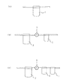
例えば、従来は、図7(a)に例示するように、高効率なメインフィルタ1だけによって要求される燃料の清浄度が維持されていたのに対して、次世代ディーゼルエンジンの分野では、そのような構成によっては要求される燃料の清浄度が維持し得ないことが生じている。そこで、要求される燃料の清浄度を維持するためには、図7(b)に例示するようなプレフィルタ2とメインフィルタ1とのポンプ3を介した組み合わせや、更には図7(c)に例示するようなプレフィルタ2と二つのメインフィルタ1とのポンプ3を介した組み合わせというような構成が必要となる。
For example, conventionally, as illustrated in FIG. 7A, the cleanliness of fuel required only by the high-efficiency main filter 1 has been maintained, whereas in the field of next-generation diesel engines, In some configurations, the required cleanliness of the fuel cannot be maintained. Therefore, in order to maintain the required cleanliness of the fuel, a combination of the pre-filter 2 and the main filter 1 as illustrated in FIG. 7B through the
しかしながら、図7(b)や図7(c)のような濾過システムを構築する場合、どうしてもスペース効率が低下し、その上、コスト的にも割高となる。そこで、図8に示すような従来から知られている複数枚の濾材11、12を重ね合わせた二重構造の濾過体13を使用することも考えられるが、この場合には各濾材11、12のそれぞれにケーキ層による効果をもたらすことができない。つまり、フィルタ装置では、その使用に伴い濾過体の表面に濾過対象物である異物が堆積したケーキ層が形成され、これによって濾過効率が維持される。ところが、図8に例示するような二重構造の濾過体13の場合、流体の流入側である表層側の濾材11にはケーキ層が形成されるのに対して、流体の流出側である次層側の濾材12にはケーキ層が形成され得ない。次層側の濾材12は、表層側の濾材11に密着しているからである。このため、どうしても濾過効率が低下し易くなるという問題がある。
However, when constructing a filtration system as shown in FIGS. 7B and 7C, the space efficiency is inevitably lowered, and the cost is also increased. Therefore, it is conceivable to use a
この点、特許文献1には、筒状のフィルタエレメントの内側に小径の筒状のフィルタエレメントを組み込んで二重構造にしたフィルタ装置が記載されている。このようなフィルタ装置であれば、外周側のフィルタエレメントが有する濾過体ばかりでなく、内周側のフィルタエレメントが有する濾過体にもケーキ層の生成を促すことができる。 In this regard, Patent Document 1 describes a filter device having a double structure by incorporating a small-diameter cylindrical filter element inside a cylindrical filter element. If it is such a filter apparatus, the production | generation of a cake layer can be promoted not only to the filter body which the filter element of an outer peripheral side has but to the filter body which the filter element of an inner peripheral side has.
しかしながら、特許文献1に記載されたようなフィルタ装置では、筒状のフィルタエレメントの内側に小径の筒状のフィルタエレメントを組み込んで二重構造にするという構造上、どうしてもフィルタ装置全体の外径が大径化してしまい、装置の大型化を招くという問題がある。しかも、径が異なる二つのフィルタエレメントを組み込むという構造上、構造が複雑化し、組立性も低下してしまうという問題も生ずる。 However, in the filter device described in Patent Document 1, the outer diameter of the entire filter device is inevitably increased due to the structure of incorporating a small-diameter cylindrical filter element inside the cylindrical filter element into a double structure. There is a problem that the diameter is increased and the size of the apparatus is increased. In addition, the structure of incorporating two filter elements having different diameters complicates the structure and causes problems in assembly.
本発明は、装置全体を大型化させず、構造の複雑化や組立性の低下を招来せずに、濾過効率を向上させ、しかもその濾過効率を維持することができるフィルタ装置を提供することである。 The present invention provides a filter device capable of improving the filtration efficiency and maintaining the filtration efficiency without increasing the overall size of the device, causing the structure to be complicated, and causing no deterioration in assembly. is there.
本発明のフィルタ装置は、一面が開口した筒状のハウジングと、前記ハウジング内に収容され、複数枚のシート状の濾材が隙間を開けて積層配置されて形成された濾過体を波形形状に形状保持させて形成されたフィルタエレメントと、前記フィルタエレメントに対する流体の流入側と流出側とを区分けして前記ハウジング内で前記フィルタエレメントを保持する機構と、を備える。 The filter device of the present invention has a tubular housing having an opening on one side, and a filter body that is accommodated in the housing and is formed by laminating a plurality of sheet-like filter media with a gap therebetween. A filter element formed to be held, and a mechanism for holding the filter element in the housing by dividing an inflow side and an outflow side of fluid with respect to the filter element.
本発明の濾過体は、複数枚のシート状の濾材が隙間を開けて積層配置されて形成されている。 The filter body of the present invention is formed by laminating and arranging a plurality of sheet-like filter media with a gap.
本発明によれば、単一の濾材からなる濾過体を用いるフィルタ装置との比較において、濾過体全体の厚みが若干厚くなる程度の変更だけしか生じさせず、したがって、装置全体を大型化させず、構造の複雑化や組立性の低下を招来せずに、複数枚の濾材により濾過効率を向上させることができ、しかも、各濾材にケーキ層の生成を促すことができるので、向上した濾過効率を維持することができる。 According to the present invention, in comparison with a filter device using a filter body made of a single filter medium, only the change to the extent that the thickness of the entire filter body is slightly increased is caused, and therefore the entire apparatus is not enlarged. The filtration efficiency can be improved with multiple filter media without complicating the structure and degrading the assembly, and each filter media can promote the formation of a cake layer. Can be maintained.
本発明の実施の一形態を図1ないし図5に基づいて説明する。本実施の形態は、燃料を濾過するための燃料フィルタ装置への適用例である。 An embodiment of the present invention will be described with reference to FIGS. This embodiment is an application example to a fuel filter device for filtering fuel.
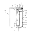
図1は、一部を切り欠いて示すフィルタ装置の正面図である。本実施の形態のフィルタ装置101、エンジン等に設けられたフィルタヘッド(いずれも図示せず)に着脱自在に取り付けられる構造を有している。つまり、フィルタヘッドは、フィルタ装置101による濾過を必要とする燃料の流路中に配置され、濾過前の燃料をフィルタ装置101に供給する領域と、濾過後の燃料をフィルタ装置101から供給される領域とを有している。フィルタヘッドは、管状部材(図示せず)を有しており、この管状部材の外周側が濾過前の燃料をフィルタ装置101に供給する領域となり、管状部材の内周側が濾過後の燃料をフィルタ装置101から供給される領域として形成されている。フィルタ装置101は、そのようなフィルタヘッドに装着されることにより、濾過前の燃料を濾過してフィルタ装置に戻すように構造を有している。
FIG. 1 is a front view of a filter device shown with a part cut away. The
フィルタ装置101は、図示しないフィルタヘッドに着脱自在に取り付けられるハウジング102を有している。ハウジング102は、金属薄板、すなわち、鉄板による円筒状の下ハウジング103を有する。下ハウジング103は、一端(図1中の下端)が閉鎖され、他端(図1中の上端)が開口するキャップ形状を有している。下ハウジング103の上面開口部分には、リング状の上ハウジング104が加締めにより固定されている。そして、上ハウジング104には、円筒状のパッキング105が加締めによって固定されている。パッキング105は、図示しないフィルタヘッドにフィルタ装置101を取り付けた際、両者の間の密閉性を保つ機能を果たす。
The
ハウジング102の内部には、フィルタエレメント106が内蔵されている。フィルタエレメント106は、多数の穴107がメッシュ状に開口した内筒108の外側に円筒状の濾過体109が取り付けられて形成されている。これらの内筒108と濾過体109とは、一対の円板状の保持プレート110a,110bによって一体に接着保持されている。
A
フィルタ装置101は、フィルタエレメント106に対する燃料の流入側と流出側とを区分けしてハウジング102の内部でフィルタエレメント106を保持する機構を有している。この機構として、フィルタ装置101は、コイルスプリング111とカバー112とを有する。
The
コイルスプリング111は、下ハウジング103の閉鎖端部側でフィルタエレメント106を弾性的に支持する。このようなコイルスプリング111は、下ハウジング103の閉鎖端部内壁とフィルタエレメント106を構成する一方の保持プレート110aとの間に位置付けられている。当該一方の保持プレート110aは、コイルスプリング111の座りを良好にするために中央部が窪んだ形状となっている。図1中、この窪んでコイルスプリング111の座りを良好にする部分を符号aで示す。
The coil spring 111 elastically supports the
カバー112は、下ハウジング103の内径と略同一径を有する円板状の隔壁113の中央部にねじ部114を有する部材である。このようなカバー112とフィルタエレメント106との間にはパッキング115が挟み込まれ、燃料の流入側と流出側とを区分けしている。
The
パッキング115は、フィルタエレメント106を構成するもう一方の保持プレート110bに当接している。当該もう一方の保持プレート110bは、パッキング115の座りを良好にするために中央部が窪んだ形状となっている。図1中、この窪んでパッキング115の座りを良好にする部分を符号bで示す。
The
カバー112には、上ハウジング104がスポット溶接等で取り付けられている。このような上ハウジング104が取り付けられたカバー112は、コイルスプリング111、フィルタエレメント106、パッキング115が順に収容された下ハウジング103に挿入され、この状態で下ハウジング103の口元と上ハウジング104の外周部を共に加締めることによって下ハウジング103に取り付けられる。
The
カバー112のねじ部114は、図示しないフィルタヘッドに対するフィルタ装置101のねじ止め固定を可能にする。更に、隔壁113の一部には流通孔116が形成されている。
The
こうして、コイルスプリング111とパッキング115とカバー112とが設けられることにより、フィルタエレメント106は、フィルタエレメント106に対する燃料の流入側と流出側とを区分けしてハウジング102の内部で保持されることになる。つまり、フィルタヘッドにおいては、ねじ部114に螺合する部分が前述した濾過前の燃料を供給する領域と濾過後の燃料を供給される領域とを区分けする管状部材となっている。したがって、フィルタ装置101では、いずれも図示しないフィルタヘッドの管状部材の外周側からパッキング105の内周側で燃料の供給を受け、流通孔116を通して供給された燃料をフィルタエレメント106の外周側に導く。この領域がフィルタエレメント106に対する燃料の流入側である。そして、燃料はフィルタエレメント106の外周側から濾過体109を通りフィルタエレメント106の内周側に至り、その過程で濾過される。濾過後の燃料は、ねじ部114に螺合するフィルタヘッドの管状部材の内周側に供給される。したがって、この領域がフィルタエレメント106からの燃料の流出側である。
Thus, by providing the coil spring 111, the packing 115, and the
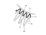
図2は、濾過体109の平面図である。濾過体109は、一対の保持プレート110a,110bの間で、波形形状で保持されている。つまり、濾過体109は、当初はシート形状をしており、波形形状に形が付され、全体がドーナツ形状となるように環状に両端が繋ぎ合わされて形成されている。図2に示すように、このような濾過体109は、多層構造となっている。以下、濾過体109の多層構造について詳細に説明する。
FIG. 2 is a plan view of the
図3は、構造を示すために拡大した濾過体109の平面図である。濾過体109は、一例として、二枚の濾材117a,117bを有している。これらの二枚の濾材117a,117bは、メッシュ材118の表裏面に保持されている。メッシュ材118は、メッシュ構造体119の間に無数の空間部120を有している。したがって、空間部120の存在により、二枚の濾材117a,117bは、隙間を開けて配置されることになる。このような濾材117a,117bは、一例として、ガラス、ポリエステル、セルロース等の材料から構成される。二枚の濾材117a,117bのうち、外周側に位置付けられるのは濾材117a、内周側に位置付けられるのは濾材117bである。
FIG. 3 is a plan view of the
図4は、濾過体109に用いる濾材のバリエーションを例示する模式図である。
FIG. 4 is a schematic view illustrating variations of the filter medium used for the
図4(a)に例示するのは、外周側に位置付けられる一方の濾材117aをプレ濾材とし、内周側に位置付けられるもう一方の濾材117bをメイン濾材とした構造の濾過体109である。一例として、5μmのダスト捕捉効率として、一方の濾材117aは50%、もう一方の濾材117bは90%程度のものが用いられる。
Illustrated in FIG. 4A is a
図4(b)に例示するのは、二枚の濾材117a,117bのそれぞれをメイン濾材として構成した濾過体109である。一例として、5μmのダスト捕捉効率として、いずれの濾材117a,117bも90%程度のものが用いられる。
FIG. 4B illustrates a
図4(c)に例示するのは、三枚の濾材117a,117b,117cを有する濾過体109である。メッシュ材118が二枚用意され、一方のメッシュ材118aの表裏面にはプレ濾材となる一枚の濾材117aとメイン濾材となる一枚の濾材117bとが保持されている。そして、もう一方のメッシュ材118bの表裏面には、メイン濾材となる一枚の濾材117bと、同様にメイン濾材となる一枚の濾材117cとが保持されている。一例として、5μmのダスト捕捉効率として、プレ濾材となる濾材117aは50%、メイン濾材となる二枚の濾材117b,117cは90%程度のものが用いられる。
FIG. 4C illustrates a
このような構成において、濾過すべき燃料は、パッキング105の内周側から流通孔116を通ってフィルタエレメント106の外周側に導かれる。そして、フィルタエレメント106の外周側から濾過体109を通りフィルタエレメント106の内周側に至り、その過程で濾過される。濾過後の燃料は、ねじ部114に螺合するフィルタヘッドの管状部材の内周側に供給され、フィルタヘッドの側の図示しないエンジンに供給される。
In such a configuration, the fuel to be filtered is guided from the inner peripheral side of the packing 105 to the outer peripheral side of the
このようなフィルタエレメント106による燃料の濾過過程において、フィルタエレメント106は、複数枚の濾材117(117a,117b又は117a,117b,117c)が積層された濾過体109により、優れた異物の濾過効率を発揮する。例えば、図4(a)、(b)、(c)に例示するバリエーションを用いて説明すると、図4(a)に例示する濾過体109では、プレ濾材となる一方の濾材117aのダスト捕捉効率は50%、メイン濾材となるもう一方の濾材117bのダスト捕捉効率は90%程度であることから、この濾過体109のダスト濾側効率は95%となる。例えば、燃料に100個の異物が含まれていると想定した場合、プレ濾材となる一方の濾材117aを通過することで50個の異物が濾過され、残りの50個の異物がメイン濾材となるもう一方の濾材117bを通過することで5個となるからである。同様に、図4(b)に例示する濾過体109では、いずれもメイン濾材となる一方の濾材117aともう一方の濾材117bとのダスト捕捉効率はいずれも90%程度であることから、この濾過体109のダスト濾側効率は99%となる。例えば、燃料に100個の異物が含まれていると想定した場合、一方の濾材117aを通過することで90個の異物が濾過され、残りの10個の異物がもう一方の濾材117bを通過することで1個となるからである。更に、図4(c)に例示する濾過体109では、プレ濾材となる一枚の濾材117aのダスト捕捉効率は50%、メイン濾材となる二枚の濾材117b,117cのそれぞれのダスト捕捉効率は90%程度であることから、この濾過体109のダスト濾側効率は99.5%となる。例えば、燃料に100個の異物が含まれていると想定した場合、プレ濾材となる一枚の濾材117aを通過することで50個の異物が濾過され、残りの50個の異物がメイン濾材となる一方の濾材117bを通過することで5個となり、残りの5個の異物がメイン濾材となるもう一方の濾材117cを通過することで0.5個となるからである。このように、本実施の形態のフィルタエレメント106によれば、複数枚の濾材117(117a,117b又は117a,117b,117c)が積層された濾過体109による優れた異物の濾過効率を得ることができる。
In such a fuel filtering process by the
また、フィルタエレメント106では、濾過体109を構成する複数枚の濾材117(117a,117b又は117a,117b,117c)は、メッシュ材118が有する無数の空間部120の存在により、隙間を開けて配置されることになる。このため、各層の濾材117(117a,117b又は117a,117b,117c)のそれぞれに、ケーキ層の生成を促すことができ、濾過効率を維持することができる。
Further, in the
したがって、本実施の形態のフィルタ装置101によれば、単一の濾過体を用いる従来構造のフィルタ装置との比較において、濾過体109の全体の厚みが若干厚くなる程度の変更だけしか生じさせず、したがって、装置全体を大型化させず、構造の複雑化や組立性の低下を招来せずに、複数枚の濾材117(117a,117b又は117a,117b,117c)により濾過効率を向上させることができ、しかも、各濾材117(117a,117b又は117a,117b,117c)にケーキ層の生成を促すことができるので、濾過効率を維持することができる。
Therefore, according to the
図5は、別の実施の一形態として、構造を示すために拡大した濾過体109の平面図である。先の実施の形態と同一部分は同一符号で示しその説明も省略する。
FIG. 5 is a plan view of a
本実施の形態では、濾過体109の構成要素として、メッシュ材118が設けられず、二枚の濾材117a,117bの形状の工夫だけによってそれらの二枚の濾材117a,117bを隙間を開けて積層配置している。つまり、二枚の濾材117a,117bは、波型形状をなす波の高さをそれぞれ違えて配置されている。本実施の形態の場合、外周側に位置する一方の濾材117aの方が波型形状をなす波の高さが高い。したがって、二枚の濾材117a,117bの間には、空間部121が形成されている。
In the present embodiment, the
本実施の形態においても、前述した実施の形態と同様に、二枚の濾材117a,117bについて、その濾過効率を違えたり、同一の濾過効率を有するものを用いたり、様々なバリエーションを生成することができる。例えば、外周側の一方の濾材117aは濾過効率が比較的に低いプレ濾材とし、内周側のもう一方の濾材117bは濾過効率が比較的に高いメイン部材としたり、二枚の濾材117a,117bのそれぞれを濾過効率が比較的に高いメイン濾材としたりするようなことが可能である。濾過体109は、そのような二枚の濾材117a,117bにより、優れた異物の濾過効率を発揮する。そして、濾過体109は、二枚の濾材117a,117bの間の空間部121の存在により、各層の濾材117a,117bのそれぞれにケーキ層の生成を促すことができ、濾過効率を維持することができる。
Also in the present embodiment, similar to the above-described embodiment, the two
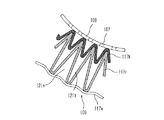
図6は、更に別の実施の一形態として、構造を示すために拡大した濾過体109の平面図である。先の二つの実施の形態と同一部分は同一符号で示しその説明も省略する。
FIG. 6 is a plan view of a
本実施の形態では、濾過体109の構成要素として、メッシュ材118が設けられず、三枚の濾材117a,117b,117cの形状の工夫だけによってそれらの三枚の濾材117a,117b,117cを隙間を開けて積層配置している。つまり、濾過体109は、流体の流入側と流出側とにそれぞれ配置された第1の濾材117aと第2の濾材117bとの間に当該第1及び第2の濾材117a,117bが有している波形形状をなす波の高さよりも波の高さが高い波形形状を有する中間濾材117cを介在させて形成されている。第1の濾材117aと第2の濾材117bとは、波形形状をなす波の高さが同一であっても、また異なっても良い。したがって、第1の濾材117aと中間濾材117cとの間には空間部121aが形成され、中間濾材117cと第2の濾材117bとの間には空間部121bが形成されている。
In the present embodiment, the
本実施の形態においても、三枚の濾材117a,117b,117cについて、その濾過効率を違えたり、同一の濾過効率を有するものを用いたり、様々なバリエーションを生成することができる。例えば、最外周側の第1の濾材117aは濾過効率が比較的に低いプレ濾材とし、内周側の二枚の中間濾材117c及び第2の濾材117bは濾過効率が比較的に高いメイン部材としたり、第1の濾材117aと中間濾材117cと第2の濾材117bとのそれぞれを濾過効率が比較的に高いメイン濾材としたりするようなことが可能である。濾過体109は、そのような各層の濾材117(第1の濾材117a、中間濾材117c、第2の濾材117b)により、優れた異物の濾過効率を発揮する。そして、濾過体109は、第1の濾材117aと中間濾材117cとの間の空間部121a、中間濾材117cと第2の濾材117bとの間の空間部121bの存在により、各層の濾材117(第1の濾材117a、中間濾材117c、第2の濾材117b)のそれぞれにケーキ層の生成を促すことができ、濾過効率を維持することができる。
Also in the present embodiment, the three
102 ハウジング
106 フィルタエレメント
109 濾過体
117 濾材
117a 濾材、第1の濾材
117b 濾材、第2の濾材
117c 濾材、中間濾材
118(118a,118b) メッシュ材
120 空間部(隙間)
121(121a,121b) 空間部(隙間)
102
121 (121a, 121b) Space (gap)
Claims (12)
前記ハウジング内に収容され、複数枚のシート状の濾材が隙間を開けて積層配置されて形成された濾過体を波形形状に形状保持させて形成されたフィルタエレメントと、
前記フィルタエレメントに対する流体の流入側と流出側とを区分けして前記ハウジング内で前記フィルタエレメントを保持する機構と、
を備えるフィルタ装置。 A cylindrical housing with one side open;
A filter element that is housed in the housing, and is formed by holding a filter body formed by laminating and arranging a plurality of sheet-like filter media with a gap therebetween;
A mechanism for separating the inflow side and the outflow side of the fluid with respect to the filter element and holding the filter element in the housing;
A filter device comprising:
複数枚のシート状の濾材が隙間を開けて積層配置されて形成されている、濾過体。 A filter body that is used while being held in a waveform shape in a filter element of a filter device,
A filter body formed by laminating a plurality of sheet-like filter media with a gap therebetween.
The filter body according to any one of claims 7 to 11, wherein the filter body includes at least two filter media having the same filtration efficiency.
Priority Applications (5)
| Application Number | Priority Date | Filing Date | Title |
|---|---|---|---|
| JP2005316532A JP2007117945A (en) | 2005-10-31 | 2005-10-31 | Filter device |
| EP06822498A EP1952869B1 (en) | 2005-10-31 | 2006-10-27 | Filter device and filter element |
| DE602006019130T DE602006019130D1 (en) | 2005-10-31 | 2006-10-27 | FILTER DEVICE AND FILTER ELEMENT |
| US12/091,876 US20080308488A1 (en) | 2005-10-31 | 2006-10-27 | Filter Apparatus and Filter Body |
| PCT/JP2006/321537 WO2007052563A1 (en) | 2005-10-31 | 2006-10-27 | Filter device and filtration body |
Applications Claiming Priority (1)
| Application Number | Priority Date | Filing Date | Title |
|---|---|---|---|
| JP2005316532A JP2007117945A (en) | 2005-10-31 | 2005-10-31 | Filter device |
Publications (1)
| Publication Number | Publication Date |
|---|---|
| JP2007117945A true JP2007117945A (en) | 2007-05-17 |
Family
ID=38005715
Family Applications (1)
| Application Number | Title | Priority Date | Filing Date |
|---|---|---|---|
| JP2005316532A Pending JP2007117945A (en) | 2005-10-31 | 2005-10-31 | Filter device |
Country Status (5)
| Country | Link |
|---|---|
| US (1) | US20080308488A1 (en) |
| EP (1) | EP1952869B1 (en) |
| JP (1) | JP2007117945A (en) |
| DE (1) | DE602006019130D1 (en) |
| WO (1) | WO2007052563A1 (en) |
Cited By (4)
| Publication number | Priority date | Publication date | Assignee | Title |
|---|---|---|---|---|
| JP2013519825A (en) * | 2010-02-12 | 2013-05-30 | ドナルドソン カンパニー,インコーポレイティド | Liquid filter media |
| JP2013533802A (en) * | 2010-07-12 | 2013-08-29 | ランデュストリエル デュ ポナン | Sterilization filter and filtration cartridge incorporating the filter |
| KR101744557B1 (en) | 2011-06-08 | 2017-06-20 | 코웨이 주식회사 | Method for manufacturing filter and filter thereof |
| CN111085021A (en) * | 2018-10-24 | 2020-05-01 | 帕尔公司 | Support and drainage material, filter, and method of use |
Families Citing this family (6)
| Publication number | Priority date | Publication date | Assignee | Title |
|---|---|---|---|---|
| GB2450735B (en) * | 2007-07-05 | 2012-11-28 | Air Safety Ltd | Air filter assembly |
| US20130220918A1 (en) * | 2012-02-24 | 2013-08-29 | Insonic Company | Double-layer filter strcutre |
| JP2014095357A (en) * | 2012-11-12 | 2014-05-22 | Daimaru Kogyo Service Kk | Fuel injection system and removal method of impurity |
| US9868083B2 (en) * | 2014-06-24 | 2018-01-16 | Robovent Products Group, Inc. | Filter media cartridge |
| US20160199757A1 (en) * | 2015-01-08 | 2016-07-14 | In-Tec Water Products, LLC. | Filter cartridge with elliptical shaped pleats |
| EP3474967A4 (en) * | 2016-06-24 | 2020-02-12 | K & N Engineering, Inc. | Compound air filter |
Citations (2)
| Publication number | Priority date | Publication date | Assignee | Title |
|---|---|---|---|---|
| JP2002129925A (en) * | 2000-10-27 | 2002-05-09 | Buko Sangyo Kk | Oil filter |
| JP2003175309A (en) * | 2002-11-11 | 2003-06-24 | Hiroshi Miyata | Filter element |
Family Cites Families (14)
| Publication number | Priority date | Publication date | Assignee | Title |
|---|---|---|---|---|
| US1101811A (en) | 1910-12-07 | 1914-06-30 | Barber Colman Co | Bobbin-holder. |
| US2101811A (en) * | 1935-12-28 | 1937-12-07 | Alvin W Franzmeier | Filter pad |
| US3227600A (en) * | 1962-12-18 | 1966-01-04 | Kenneth M Holland | Formable honeycomb |
| US3260370A (en) * | 1963-09-05 | 1966-07-12 | Gen Motors Corp | Drycleaning filter element |
| US3368687A (en) * | 1965-01-11 | 1968-02-13 | Gen Motors Corp | Series parallel sheet media filter element |
| CH594437A5 (en) * | 1975-12-04 | 1978-01-13 | Erhard Charles Andreae | |
| JPS6034329Y2 (en) | 1980-03-19 | 1985-10-14 | 和興産業株式会社 | filter body |
| CH678154A5 (en) * | 1989-04-26 | 1991-08-15 | Robert Andreae | |
| JP2000130142A (en) | 1998-10-23 | 2000-05-09 | Nissan Diesel Motor Co Ltd | Filter for internal combustion engine |
| US6224655B1 (en) * | 1998-11-03 | 2001-05-01 | Pierre Messier | Biostatic air filter |
| US6315130B1 (en) | 1999-01-07 | 2001-11-13 | Cuno Incorporated | Pleated filter element |
| US6569330B1 (en) * | 2000-07-19 | 2003-05-27 | Velcon Filters, Inc. | Filter coalescer cartridge |
| DE10155879C2 (en) | 2001-11-14 | 2003-09-11 | Inatec Gmbh | Filter element and method and plant for its production |
| DE10250969A1 (en) | 2002-11-02 | 2004-05-19 | Hydac Filtertechnik Gmbh | Filter cylinder for hydraulic oil, in a hydraulic system, has a pleated structure with pleat folds covering the radial gap between the outer mantle and inner tube and shorter intermediate folds |
-
2005
- 2005-10-31 JP JP2005316532A patent/JP2007117945A/en active Pending
-
2006
- 2006-10-27 EP EP06822498A patent/EP1952869B1/en not_active Expired - Fee Related
- 2006-10-27 DE DE602006019130T patent/DE602006019130D1/en active Active
- 2006-10-27 WO PCT/JP2006/321537 patent/WO2007052563A1/en active Application Filing
- 2006-10-27 US US12/091,876 patent/US20080308488A1/en not_active Abandoned
Patent Citations (2)
| Publication number | Priority date | Publication date | Assignee | Title |
|---|---|---|---|---|
| JP2002129925A (en) * | 2000-10-27 | 2002-05-09 | Buko Sangyo Kk | Oil filter |
| JP2003175309A (en) * | 2002-11-11 | 2003-06-24 | Hiroshi Miyata | Filter element |
Cited By (6)
| Publication number | Priority date | Publication date | Assignee | Title |
|---|---|---|---|---|
| JP2013519825A (en) * | 2010-02-12 | 2013-05-30 | ドナルドソン カンパニー,インコーポレイティド | Liquid filter media |
| US10226723B2 (en) | 2010-02-12 | 2019-03-12 | Donaldson Company, Inc. | Liquid filtration media, filter elements and methods |
| US11565206B2 (en) | 2010-02-12 | 2023-01-31 | Donaldson Company, Inc. | Liquid filtration media, filter elements and methods |
| JP2013533802A (en) * | 2010-07-12 | 2013-08-29 | ランデュストリエル デュ ポナン | Sterilization filter and filtration cartridge incorporating the filter |
| KR101744557B1 (en) | 2011-06-08 | 2017-06-20 | 코웨이 주식회사 | Method for manufacturing filter and filter thereof |
| CN111085021A (en) * | 2018-10-24 | 2020-05-01 | 帕尔公司 | Support and drainage material, filter, and method of use |
Also Published As
| Publication number | Publication date |
|---|---|
| EP1952869A4 (en) | 2009-11-04 |
| EP1952869A1 (en) | 2008-08-06 |
| WO2007052563A1 (en) | 2007-05-10 |
| US20080308488A1 (en) | 2008-12-18 |
| DE602006019130D1 (en) | 2011-02-03 |
| EP1952869B1 (en) | 2010-12-22 |
Similar Documents
| Publication | Publication Date | Title |
|---|---|---|
| JP2007117945A (en) | Filter device | |
| JP3161596B2 (en) | Dual medium fuel filter and method for manufacturing dual medium fuel filter | |
| US7597734B2 (en) | Multi-element filter arrangement and methods | |
| JP6559651B2 (en) | Liquid filter assembly | |
| US8051989B1 (en) | Support structure for a filter | |
| US20020056684A1 (en) | Multilayer filter element | |
| EP2950907B1 (en) | Filter with dual pleat pack | |
| JP2016501119A (en) | Filter element | |
| WO2011096325A1 (en) | Filter element, filter device, and method for manufacturing filter element | |
| US20080308485A1 (en) | Self-adjusting minimum load filter cartridge and bypass valve | |
| EP2950908B1 (en) | Filter with dual pleat pack | |
| JP2014205097A (en) | Filter device, filtration method using the same, and manufacturing method of filtration fluid using the same | |
| JP3755487B2 (en) | Oil filter for construction machinery | |
| JPH03175141A (en) | Fuel filter for internal combustion engine | |
| US20180264383A1 (en) | System and method for oil filtration in bypass mode | |
| JP2008119579A (en) | Filtration device | |
| JP2012040455A (en) | Filter element and filter device | |
| JP6998261B2 (en) | Filter device | |
| JPH08100622A (en) | Filter element | |
| CN1762537A (en) | Cleaner filter core assembly | |
| JPH09313812A (en) | Spiral filter element | |
| JP2002085928A (en) | Filter device | |
| JP2000042314A (en) | Filter | |
| JP5821774B2 (en) | Filter element for fuel filter and fuel filter device including the same | |
| JP3196081B2 (en) | Filter media |
Legal Events
| Date | Code | Title | Description |
|---|---|---|---|
| A621 | Written request for application examination |
Free format text: JAPANESE INTERMEDIATE CODE: A621 Effective date: 20081020 |
|
| A131 | Notification of reasons for refusal |
Free format text: JAPANESE INTERMEDIATE CODE: A131 Effective date: 20111115 |
|
| A02 | Decision of refusal |
Free format text: JAPANESE INTERMEDIATE CODE: A02 Effective date: 20120306 |