JP2007113874A - Freezer for trailer - Google Patents
Freezer for trailer Download PDFInfo
- Publication number
- JP2007113874A JP2007113874A JP2005307855A JP2005307855A JP2007113874A JP 2007113874 A JP2007113874 A JP 2007113874A JP 2005307855 A JP2005307855 A JP 2005307855A JP 2005307855 A JP2005307855 A JP 2005307855A JP 2007113874 A JP2007113874 A JP 2007113874A
- Authority
- JP
- Japan
- Prior art keywords
- engine
- electric compressor
- power generation
- compressor
- rotational speed
- Prior art date
- Legal status (The legal status is an assumption and is not a legal conclusion. Google has not performed a legal analysis and makes no representation as to the accuracy of the status listed.)
- Pending
Links
Images


Classifications
-
- F—MECHANICAL ENGINEERING; LIGHTING; HEATING; WEAPONS; BLASTING
- F25—REFRIGERATION OR COOLING; COMBINED HEATING AND REFRIGERATION SYSTEMS; HEAT PUMP SYSTEMS; MANUFACTURE OR STORAGE OF ICE; LIQUEFACTION SOLIDIFICATION OF GASES
- F25B—REFRIGERATION MACHINES, PLANTS OR SYSTEMS; COMBINED HEATING AND REFRIGERATION SYSTEMS; HEAT PUMP SYSTEMS
- F25B27/00—Machines, plants or systems, using particular sources of energy
-
- B—PERFORMING OPERATIONS; TRANSPORTING
- B60—VEHICLES IN GENERAL
- B60P—VEHICLES ADAPTED FOR LOAD TRANSPORTATION OR TO TRANSPORT, TO CARRY, OR TO COMPRISE SPECIAL LOADS OR OBJECTS
- B60P3/00—Vehicles adapted to transport, to carry or to comprise special loads or objects
- B60P3/20—Refrigerated goods vehicles
-
- F—MECHANICAL ENGINEERING; LIGHTING; HEATING; WEAPONS; BLASTING
- F25—REFRIGERATION OR COOLING; COMBINED HEATING AND REFRIGERATION SYSTEMS; HEAT PUMP SYSTEMS; MANUFACTURE OR STORAGE OF ICE; LIQUEFACTION SOLIDIFICATION OF GASES
- F25B—REFRIGERATION MACHINES, PLANTS OR SYSTEMS; COMBINED HEATING AND REFRIGERATION SYSTEMS; HEAT PUMP SYSTEMS
- F25B49/00—Arrangement or mounting of control or safety devices
- F25B49/02—Arrangement or mounting of control or safety devices for compression type machines, plants or systems
- F25B49/025—Motor control arrangements
-
- F—MECHANICAL ENGINEERING; LIGHTING; HEATING; WEAPONS; BLASTING
- F25—REFRIGERATION OR COOLING; COMBINED HEATING AND REFRIGERATION SYSTEMS; HEAT PUMP SYSTEMS; MANUFACTURE OR STORAGE OF ICE; LIQUEFACTION SOLIDIFICATION OF GASES
- F25D—REFRIGERATORS; COLD ROOMS; ICE-BOXES; COOLING OR FREEZING APPARATUS NOT OTHERWISE PROVIDED FOR
- F25D29/00—Arrangement or mounting of control or safety devices
- F25D29/003—Arrangement or mounting of control or safety devices for movable devices
-
- F—MECHANICAL ENGINEERING; LIGHTING; HEATING; WEAPONS; BLASTING
- F25—REFRIGERATION OR COOLING; COMBINED HEATING AND REFRIGERATION SYSTEMS; HEAT PUMP SYSTEMS; MANUFACTURE OR STORAGE OF ICE; LIQUEFACTION SOLIDIFICATION OF GASES
- F25B—REFRIGERATION MACHINES, PLANTS OR SYSTEMS; COMBINED HEATING AND REFRIGERATION SYSTEMS; HEAT PUMP SYSTEMS
- F25B2327/00—Refrigeration system using an engine for driving a compressor
-
- F—MECHANICAL ENGINEERING; LIGHTING; HEATING; WEAPONS; BLASTING
- F25—REFRIGERATION OR COOLING; COMBINED HEATING AND REFRIGERATION SYSTEMS; HEAT PUMP SYSTEMS; MANUFACTURE OR STORAGE OF ICE; LIQUEFACTION SOLIDIFICATION OF GASES
- F25B—REFRIGERATION MACHINES, PLANTS OR SYSTEMS; COMBINED HEATING AND REFRIGERATION SYSTEMS; HEAT PUMP SYSTEMS
- F25B2600/00—Control issues
- F25B2600/02—Compressor control
- F25B2600/021—Inverters therefor
-
- F—MECHANICAL ENGINEERING; LIGHTING; HEATING; WEAPONS; BLASTING
- F25—REFRIGERATION OR COOLING; COMBINED HEATING AND REFRIGERATION SYSTEMS; HEAT PUMP SYSTEMS; MANUFACTURE OR STORAGE OF ICE; LIQUEFACTION SOLIDIFICATION OF GASES
- F25B—REFRIGERATION MACHINES, PLANTS OR SYSTEMS; COMBINED HEATING AND REFRIGERATION SYSTEMS; HEAT PUMP SYSTEMS
- F25B2600/00—Control issues
- F25B2600/11—Fan speed control
- F25B2600/111—Fan speed control of condenser fans
-
- F—MECHANICAL ENGINEERING; LIGHTING; HEATING; WEAPONS; BLASTING
- F25—REFRIGERATION OR COOLING; COMBINED HEATING AND REFRIGERATION SYSTEMS; HEAT PUMP SYSTEMS; MANUFACTURE OR STORAGE OF ICE; LIQUEFACTION SOLIDIFICATION OF GASES
- F25B—REFRIGERATION MACHINES, PLANTS OR SYSTEMS; COMBINED HEATING AND REFRIGERATION SYSTEMS; HEAT PUMP SYSTEMS
- F25B2600/00—Control issues
- F25B2600/11—Fan speed control
- F25B2600/112—Fan speed control of evaporator fans
Landscapes
- Engineering & Computer Science (AREA)
- Physics & Mathematics (AREA)
- Mechanical Engineering (AREA)
- Thermal Sciences (AREA)
- General Engineering & Computer Science (AREA)
- Chemical & Material Sciences (AREA)
- Combustion & Propulsion (AREA)
- Health & Medical Sciences (AREA)
- Public Health (AREA)
- Transportation (AREA)
- Devices That Are Associated With Refrigeration Equipment (AREA)
- Control Of Positive-Displacement Pumps (AREA)
Abstract
Description
本発明は、トレーラー用冷凍装置に関し、特に、小型化および軽量化対策に係るものである。 The present invention relates to a refrigeration apparatus for trailers, and particularly relates to measures for downsizing and weight reduction.
従来より、冷凍食品等を陸上輸送する冷凍車に設けられてその冷凍庫内を冷却する冷凍装置が知られている。この種の冷凍装置としては、冷凍車の走行用エンジンの動力によって発電した電力により圧縮機を駆動するものがある。 2. Description of the Related Art Conventionally, a refrigeration apparatus is known that is provided in a refrigeration vehicle that transports frozen foods and the like and cools the inside of the freezer. As this type of refrigeration apparatus, there is an apparatus that drives a compressor with electric power generated by the power of a traveling engine of a refrigeration vehicle.
ところが、この場合、冷凍車が走行停止すると圧縮機も停止するので、冷凍庫内の温度が上昇してしまうという問題があった。また、運転室を有する運転車両(トレーラーヘッド)と冷凍庫が積載される荷台車両(トレーラー)とが切り離し可能に構成されている冷凍車がある。その場合、走行用エンジンが運転車両に設けられ、冷凍装置が荷台車両に設けられることから、運転車両を交換する等で荷台車両を切り離した際、やはり圧縮機が停止するという問題があった。 However, in this case, since the compressor is stopped when the refrigeration vehicle stops running, there is a problem that the temperature in the freezer rises. In addition, there is a freezing vehicle in which a driving vehicle (trailer head) having a driver's cab and a loading platform vehicle (trailer) on which a freezer is loaded are separable. In that case, since the driving engine is provided in the driving vehicle and the refrigeration device is provided in the loading platform vehicle, there is a problem that the compressor is stopped when the loading platform vehicle is disconnected by replacing the driving vehicle.
そこで、走行用エンジンとは別に冷凍機用のエンジンを荷台車両(トレーラー)に設け、そのエンジンによって圧縮機を駆動する冷凍装置が知られている(例えば、特許文献1参照)。つまり、この冷凍装置では、走行エンジンが停止したり運転車両が切り離されても、荷台車両側で冷凍装置が継続して運転される。
しかしながら、上述した特許文献1の冷凍装置では、圧縮機がエンジンに直結されて駆動されるため、圧縮機の許容回転数の制約によりエンジンの回転数を低く抑えなければならないという問題があった。つまり、圧縮機には効率や信頼性の観点から最大許容回転数が設定されているが、この回転数はエンジンの定格回転数よりも極端に低いため、その許容回転数以下でエンジンを運転する必要がある。したがって、エンジンは低回転で高トルクを出さなければならないため、エンジンの排気量が必要以上に大きくなり、エンジンの大型化および重量増大を招くという問題があった。
However, in the above-described refrigeration apparatus of
本発明は、斯かる点に鑑みてなされたものであり、その目的とするところは、荷台車両(トレーラー)に設置され、走行用エンジンとは別のエンジンを備えて圧縮機等の冷凍機器を駆動する冷凍装置において、エンジンおよび圧縮機等を別個独立に制御することによりエンジンの小型化および軽量化を図ることである。 The present invention has been made in view of such a point, and an object of the present invention is to install a refrigerating apparatus such as a compressor, which is installed in a cargo vehicle (trailer) and has an engine different from a traveling engine. In a driving refrigeration system, the engine and the compressor are controlled separately and independently to reduce the size and weight of the engine.
第1の発明は、発電機(22)と、該発電機(22)を駆動する発電用エンジン(21)と、上記発電機(22)で発電された交流電力を直流電力に変換するコンバータ(23)と、該コンバータ(23)の直流電力を交流電力に変換するインバータ(24,25,26)と、該インバータ(24,25,26)の交流電力によってそれぞれ駆動される電動圧縮機(31)およびファン(35,36)を有する冷媒回路(30)と、上記発電用エンジン(21)、電動圧縮機(31)およびファン(35,36)の各回転数を個別に制御する制御手段(40)とを備えているものである。 The first invention includes a generator (22), a power generation engine (21) that drives the power generator (22), and a converter that converts AC power generated by the generator (22) into DC power ( 23), an inverter (24, 25, 26) for converting DC power of the converter (23) into AC power, and an electric compressor (31) driven by the AC power of the inverter (24, 25, 26), respectively ) And a refrigerant circuit (30) having a fan (35, 36), and control means for individually controlling the rotational speeds of the power generation engine (21), the electric compressor (31) and the fan (35, 36) ( 40).
上記の発明では、発電機(22)と電動圧縮機(31)との間にコンバータ(23)およびインバータ(24,25,26)を設けるようにしたので、発電用エンジン(21)の回転数が電動圧縮機(31)等の回転数に連動することはない。そこで、制御手段(40)により、発電用エンジン(21)と、電動圧縮機(31)と、ファン(35,36)とがそれぞれ異なる回転数で駆動される。したがって、例えば、発電用エンジン(21)が最適効率となる割と高い回転数で駆動しても、電動圧縮機(31)およびファン(35,36)がそれぞれ最適効率となる発電用エンジン(21)の回転数よりも低い回転数で駆動される。 In the above invention, since the converter (23) and the inverter (24, 25, 26) are provided between the generator (22) and the electric compressor (31), the rotational speed of the generator engine (21) However, it is not linked to the rotational speed of the electric compressor (31). Therefore, the control means (40) drives the power generation engine (21), the electric compressor (31), and the fans (35, 36) at different rotational speeds. Therefore, for example, even if the power generation engine (21) is driven at a rotational speed that is high enough to achieve the optimum efficiency, the electric compressor (31) and the fan (35, 36) each have the optimum efficiency (21 ) Is driven at a lower rotational speed than
また、第2の発明は、上記第1の発明において、上記制御手段(40)は、電動圧縮機(31)が最大回転数で駆動する場合、発電用エンジン(21)の回転数が上記電動圧縮機(31)の最大回転数よりも低くなるように上記発電用エンジン(21)を制御するものである。 In a second aspect based on the first aspect, the control means (40) is configured such that when the electric compressor (31) is driven at the maximum rotational speed, the rotational speed of the power generation engine (21) is The power generation engine (21) is controlled to be lower than the maximum rotational speed of the compressor (31).
上記の発明では、最大冷凍能力が必要な場合に、電動圧縮機(31)が最大回転数で駆動される。その場合でも、発電用エンジン(21)は、電動圧縮機(31)の回転数と同じ回転数で駆動する必要がなく、その最大回転数よりも低い回転数で駆動される。したがって、発電用エンジン(21)の排気量を電動圧縮機(31)により発揮し得る冷凍能力に合わす必要がない。これにより、発電用エンジン(21)を小型化させることができる。 In the above invention, when the maximum refrigeration capacity is required, the electric compressor (31) is driven at the maximum rotational speed. Even in this case, the power generation engine (21) does not need to be driven at the same rotational speed as that of the electric compressor (31), and is driven at a rotational speed lower than the maximum rotational speed. Therefore, it is not necessary to match the displacement of the power generation engine (21) with the refrigeration capacity that can be exhibited by the electric compressor (31). Thereby, the power generation engine (21) can be reduced in size.
また、第3の発明は、上記第1または第2の発明において、上記制御手段(40)は、電動圧縮機(31)が最小回転数で駆動する場合、発電用エンジン(21)の回転数が上記電動圧縮機(31)の最小回転数よりも高くなるように上記発電用エンジン(21)を制御するものである。 According to a third aspect of the present invention, in the first or second aspect of the invention, when the electric compressor (31) is driven at the minimum rotational speed, the control means (40) rotates the rotational speed of the power generation engine (21). Is for controlling the power generation engine (21) so as to be higher than the minimum rotational speed of the electric compressor (31).
上記の発明では、最小冷凍能力が必要な場合に、電動圧縮機(31)が最小回転数で駆動される。その場合でも、発電用エンジン(21)は、電動圧縮機(31)の回転数と同じ回転数で駆動する必要がなく、その最小回転数よりも高い回転数で駆動される。したがって、発電用エンジン(21)は、低回転数で高トルクを発揮する必要がない。これにより、発電用エンジン(21)の大型化が防止される。 In the above invention, when the minimum refrigerating capacity is required, the electric compressor (31) is driven at the minimum rotation speed. Even in this case, the power generation engine (21) does not need to be driven at the same rotational speed as that of the electric compressor (31), and is driven at a rotational speed higher than the minimum rotational speed. Therefore, the power generation engine (21) does not need to exhibit high torque at a low rotational speed. Thereby, the enlargement of the power generation engine (21) is prevented.
また、第4の発明は、上記第1乃至第3の発明の何れか1において、上記制御手段(40)が、上記トレーラー庫内の温度に基づいてインバータ(24,25,26)の出力を制御して電動圧縮機(31)およびファン(35,36)の各回転数を制御する冷凍機器制御部(41)を備えると共に、上記インバータ(24,25,26)の入出力状態またはコンバータ(23)の入出力状態に基づいて発電用エンジン(21)の回転数を制御するエンジン制御部(42)を備えているものである。 According to a fourth invention, in any one of the first to third inventions, the control means (40) outputs the output of the inverter (24, 25, 26) based on the temperature in the trailer cabinet. A refrigeration equipment control unit (41) that controls the rotational speeds of the electric compressor (31) and the fan (35, 36) to control the input / output state of the inverter (24, 25, 26) or the converter ( The engine control unit (42) for controlling the rotational speed of the power generation engine (21) based on the input / output state of 23) is provided.
上記の発明では、冷凍機器制御部(41)により、電動圧縮機(31)およびファン(35,36)がそれぞれ最適効率となる回転数で駆動するように各インバータ(24,25,26)が制御される。一方、エンジン制御部(42)により、インバータ(24,25,26)またはコンバータ(23)の入出力状態に基づいて発電機(22)における必要電力が求められる。そして、エンジン制御部(42)により、上記必要電力が発電されるように発電用エンジン(21)が最適効率となる回転数で制御される。つまり、発電用エンジン(21)は、電動圧縮機(31)等の回転数とは関係なく、個別に制御される。 In the above invention, each inverter (24, 25, 26) is driven by the refrigeration equipment controller (41) so that the electric compressor (31) and the fan (35, 36) are driven at the respective rotational speeds at which the optimum efficiency is achieved. Be controlled. On the other hand, the required power in the generator (22) is obtained by the engine control unit (42) based on the input / output states of the inverter (24, 25, 26) or the converter (23). Then, the power generation engine (21) is controlled by the engine control section (42) at a rotational speed at which the efficiency is optimum so that the necessary power is generated. That is, the power generation engine (21) is individually controlled regardless of the rotational speed of the electric compressor (31) or the like.
また、第5の発明は、上記第4の発明において、上記エンジン制御部(42)が、上記発電用エンジン(21)の燃料供給量を調節することによって該発電用エンジン(21)の回転数を制御するように構成されているものである。 According to a fifth aspect, in the fourth aspect, the engine control unit (42) adjusts the fuel supply amount of the power generation engine (21) to thereby adjust the rotational speed of the power generation engine (21). It is comprised so that it may control.
上記の発明では、燃料供給量を増大されば発電用エンジン(21)の回転数が上昇し、燃料供給量を減少されば発電用エンジン(21)の回転数が低下する。 In the above invention, if the fuel supply amount is increased, the rotational speed of the power generation engine (21) is increased, and if the fuel supply amount is decreased, the rotational speed of the power generation engine (21) is decreased.
また、第6の発明は、上記第5の発明において、上記発電用エンジン(21)が電子ガバナを有している。一方、上記エンジン制御部(42)は、上記電子ガバナを制御して発電用エンジン(21)の燃料供給量を調節するように構成されているものである。 In a sixth aspect based on the fifth aspect, the power generating engine (21) has an electronic governor. On the other hand, the engine control unit (42) is configured to control the electronic governor to adjust the fuel supply amount of the power generation engine (21).
上記の発明では、燃料供給量が電子ガバナ制御により調節されるので、発電用エンジン(21)の回転数が高精度に制御される。 In the above invention, since the fuel supply amount is adjusted by the electronic governor control, the rotational speed of the power generation engine (21) is controlled with high accuracy.
また、第7の発明は、上記第1乃至第3の発明の何れか1において、上記電動圧縮機(31)は、圧縮機構が回転式に構成されているものである。 According to a seventh aspect, in any one of the first to third aspects, the electric compressor (31) is configured such that the compression mechanism is a rotary type.
上記の発明では、電動圧縮機(31)の圧縮機構がスクロール式やロータリー式に構成される。この回転式圧縮機機構の場合、往復動式(例えば、レシプロ式)に比べて、始動トルクが小さい。したがって、電動圧縮機(31)の始動に必要電力が低減され、発電用エンジン(21)の必要動力が低減される。 In said invention, the compression mechanism of an electric compressor (31) is comprised by a scroll type or a rotary type. In the case of this rotary compressor mechanism, the starting torque is smaller than that of a reciprocating type (for example, reciprocating type). Therefore, the electric power required for starting the electric compressor (31) is reduced, and the necessary power of the power generation engine (21) is reduced.
また、第8の発明は、上記第1乃至第3の発明の何れか1において、上記コンバータ(23)が発電機(22)に繋がる状態と商用電源に繋がる状態とに切り換える切換スイッチ(27)を備えているものである。 According to an eighth aspect of the present invention, in any one of the first to third aspects, the changeover switch (27) for switching the converter (23) between a state connected to the generator (22) and a state connected to a commercial power source. It is equipped with.
上記の発明では、例えば、冷凍車が長時間停止する場合、発電用エンジン(21)を停止し、コンバータ(23)が陸上の商用電源に繋げられる。これにより、発電用エンジン(21)が省エネ運転される。 In the above invention, for example, when the refrigeration vehicle is stopped for a long time, the power generation engine (21) is stopped, and the converter (23) is connected to a commercial power supply on land. As a result, the power generation engine (21) is operated in an energy-saving manner.
また、第9の発明は、上記第4の発明において、上記制御手段(40)は、電動圧縮機(31)の異常を検知する圧縮機異常検知部(44)を備えている。一方、上記冷凍機器制御部(41)は、上記圧縮機異常検知部(44)が異常を検知すると、電動圧縮機(31)の回転数が所定値で固定されるようにインバータ(24)を制御するように構成されているものである。 In a ninth aspect based on the fourth aspect, the control means (40) includes a compressor abnormality detection unit (44) for detecting abnormality of the electric compressor (31). On the other hand, when the compressor abnormality detection unit (44) detects an abnormality, the refrigeration equipment control unit (41) sets the inverter (24) so that the rotational speed of the electric compressor (31) is fixed at a predetermined value. It is comprised so that it may control.
上記の発明では、圧縮機異常検知部(44)により、電動圧縮機(31)の異常状態、例えば故障寸前の状態が検知される。このような異常状態が検知されると、電動圧縮機(31)の回転数が所定値で固定される。したがって、電動圧縮機(31)は、回転数が変化しないため、その回転数変化による負担が軽減される。これにより、電動圧縮機(31)を交換する時期まで少しでも長く運転させることができる。 In the above invention, the compressor abnormality detection unit (44) detects an abnormal state of the electric compressor (31), for example, a state immediately before a failure. When such an abnormal state is detected, the rotational speed of the electric compressor (31) is fixed at a predetermined value. Therefore, since the rotation speed of the electric compressor (31) does not change, the burden due to the change in the rotation speed is reduced. Thereby, it can be made to operate as long as possible until the time when the electric compressor (31) is replaced.
また、第10の発明は、上記第9の発明において、上記圧縮機異常検知部(44)が、電動圧縮機(31)のモータの発生トルクTに基づいて該電動圧縮機(31)の異常を検知するように構成されているものである。 In a tenth aspect based on the ninth aspect, the compressor abnormality detection unit (44) detects the abnormality of the electric compressor (31) based on the torque T generated by the motor of the electric compressor (31). It is comprised so that it may detect.
上記の発明では、予め正常時のモータの発生トルクをデータとして備えていれば、その発生トルクと実際の発生トルクTとの比較で、容易に異常状態か否かが検知される。 In the above-described invention, if the normal generation torque of the motor is provided as data in advance, it is easily detected whether or not it is in an abnormal state by comparing the generation torque with the actual generation torque T.
また、第11の発明は、上記第9の発明において、上記圧縮機異常検知部(44)が、電動圧縮機(31)のモータの巻き線抵抗Rに基づいて該電動圧縮機(31)の異常を検知するように構成されているものである。 Further, in an eleventh aspect based on the ninth aspect, the compressor abnormality detection unit (44) is configured such that the compressor of the electric compressor (31) is based on the winding resistance R of the motor of the electric compressor (31). It is configured to detect an abnormality.
上記の発明では、予め正常時の巻き線抵抗値をデータとして備えていれば、その巻き線抵抗値と実際の巻き線抵抗Rとの比較で、容易に異常状態か否かが検知される。 In the above invention, if a normal winding resistance value is provided as data in advance, it is easily detected whether the winding resistance value is abnormal or not by comparing the winding resistance value with the actual winding resistance R.
また、第12の発明は、上記第9の発明において、上記圧縮機異常検知部(44)が、電動圧縮機(31)のモータ磁石の磁束Ψに基づいて該電動圧縮機(31)の異常を検知するように構成されているものである。 In addition, in a twelfth aspect based on the ninth aspect, the compressor abnormality detection unit (44) detects the abnormality of the electric compressor (31) based on the magnetic flux Ψ of the motor magnet of the electric compressor (31). It is comprised so that it may detect.
上記の発明では、予め正常時の磁束をデータとして備えていれば、その磁束と実際の磁束Ψとの比較で、容易に異常状態か否かが検知される。 In the above invention, if a normal magnetic flux is provided as data in advance, it is easily detected whether or not an abnormal state is detected by comparing the magnetic flux with the actual magnetic flux Ψ.
また、第13の発明は、上記第4の発明において、上記制御手段(40)が、発電用エンジン(21)の燃料供給量に基づいて該発電用エンジン(21)の異常を検知するエンジン異常検知部(45)を備えている。一方、上記冷凍機器制御部(41)は、上記エンジン異常検知部(45)が異常を検知すると、発電用エンジン(21)の負荷を低減するように電動圧縮機(31)およびファン(35,36)の少なくとも一方の回転数を制御するように構成されているものである。 Further, in a thirteenth aspect based on the fourth aspect, the control means (40) detects an abnormality of the power generation engine (21) based on a fuel supply amount of the power generation engine (21). It has a detector (45). On the other hand, when the engine abnormality detection unit (45) detects an abnormality, the refrigeration equipment control unit (41) detects the electric compressor (31) and the fan (35, 35) so as to reduce the load on the power generation engine (21). 36) is configured to control at least one of the rotational speeds.
上記の発明では、エンジン異常検知部(45)により、発電用エンジン(21)の異常状態、例えば故障寸前の状態が検知される。このような異常状態が検知されると、発電用エンジン(21)の負担が低減されるように、電動圧縮機(31)やファン(35,36)の運転効率の最適性に関係なく電動圧縮機(31)等が駆動され、庫内の温度制御が行われる。つまり、電動圧縮機(31)等の入力電流が低下するように駆動される。これにより、発電用エンジン(21)を交換する時期まで少しでも長く運転させることができる。 In the above invention, the engine abnormality detection unit (45) detects an abnormal state of the power generation engine (21), for example, a state immediately before a failure. When such an abnormal condition is detected, electric compression is performed regardless of the optimal operating efficiency of the electric compressor (31) and fan (35, 36) so that the load on the generator engine (21) is reduced. The machine (31) and the like are driven to control the temperature in the cabinet. That is, the electric compressor (31) or the like is driven so that the input current decreases. Thereby, it can be made to drive | operate as long as possible until the time to replace | exchange the engine (21) for electric power generation.
また、第14の発明は、上記第4の発明において、上記制御手段(40)が、ファン(35,36)の異常を検知するファン異常検知部(46)を備えている。一方、上記冷凍機器制御部(41)は、上記ファン異常検知部(46)が異常を検知すると、ファン(35,36)の回転数が所定値で固定されるようにインバータ(25,26)を制御するように構成されているものである。 In a fourteenth aspect based on the fourth aspect, the control means (40) includes a fan abnormality detection unit (46) for detecting abnormality of the fans (35, 36). On the other hand, when the fan abnormality detection unit (46) detects an abnormality, the refrigeration equipment control unit (41) causes the inverter (25, 26) to fix the rotational speed of the fan (35, 36) at a predetermined value. It is comprised so that it may control.
上記の発明では、ファン異常検知部(46)により、ファン(35,36)の異常状態、例えば故障寸前の状態が検知される。このような異常状態が検知されると、ファン(35,36)の回転数が所定値で固定される。したがって、ファン(35,36)は、回転数が変化しないため、その回転数変化による負担が軽減される。これにより、ファン(35,36)を交換する時期まで少しでも長く運転させることができる。 In the above invention, the fan abnormality detection unit (46) detects an abnormal state of the fans (35, 36), for example, a state immediately before the failure. When such an abnormal state is detected, the rotational speed of the fans (35, 36) is fixed at a predetermined value. Therefore, since the fan (35, 36) does not change the rotation speed, the burden due to the change in the rotation speed is reduced. Thereby, it can be made to drive | operate for a long time until the time of replacing | exchanging a fan (35, 36).
したがって、本発明によれば、発電用エンジン(21)と電動圧縮機(31)とファン(35,36)とを別個独立に制御できるようにしたので、発電用エンジン(21)を電動圧縮機(31)やファン(35,36)の回転数に連動させて駆動させなくてもよい。したがって、例えば低回転高トルクで発電用エンジン(21)を駆動しなくてもよいため、発電用エンジン(21)の排気量を無駄に大きくする必要がなくなる。この結果、発電用エンジン(21)の小型化および軽量化を図ることができる。 Therefore, according to the present invention, since the power generation engine (21), the electric compressor (31), and the fan (35, 36) can be controlled independently, the power generation engine (21) can be controlled by the electric compressor. (31) and the fan (35, 36) may not be driven in conjunction with the rotational speed. Therefore, for example, since it is not necessary to drive the power generation engine (21) with low rotation and high torque, there is no need to unnecessarily increase the displacement of the power generation engine (21). As a result, the power generation engine (21) can be reduced in size and weight.
また、電動圧縮機(31)等とは関係なく発電用エンジン(21)にとって最適効率となる回転数で該発電用エンジン(21)を駆動することができる。この結果、装置の省エネ化を図ることができる。 Further, regardless of the electric compressor (31) or the like, the power generation engine (21) can be driven at a rotational speed that is optimal for the power generation engine (21). As a result, energy saving of the apparatus can be achieved.
また、第7の発明によれば、電動圧縮機(31)の始動トルクを低減することができる。したがって、発電機(22)の必要発電電力を低減することができ、発電用エンジン(21)の必要動力を低減することができる。この結果、発電用エンジン(21)の小型化および軽量化を一層図ることができる。 According to the seventh aspect, the starting torque of the electric compressor (31) can be reduced. Therefore, the required generated power of the generator (22) can be reduced, and the required power of the generator engine (21) can be reduced. As a result, the power generation engine (21) can be further reduced in size and weight.
また、第8の発明によれば、コンバータ(23)を発電機(22)から切り換えて商用電源と繋げるようにしたので、例えば冷凍車が長時間走行停止するような場合、発電用エンジン(21)を駆動させる必要がなくなる。この結果、発電用エンジン(21)の省エネ化を図ることができる。 According to the eighth aspect of the invention, the converter (23) is switched from the generator (22) and connected to the commercial power source. Therefore, for example, when the refrigeration vehicle stops running for a long time, the power generation engine (21 ) Need not be driven. As a result, energy saving of the power generation engine (21) can be achieved.
また、第9〜第14の発明によれば、電動圧縮機(31)、ファン(35,36)および発電用エンジン(21)の故障寸前の異常状態を検知することができる。そして、検知されると、電動圧縮機(31)等の負担を軽減するようにしたので、交換の時期までできるだけ長く運転を持続させることができる。 Further, according to the ninth to fourteenth aspects, it is possible to detect an abnormal state immediately before a failure of the electric compressor (31), the fan (35, 36), and the power generation engine (21). When detected, the load on the electric compressor (31) and the like is reduced, so that the operation can be continued as long as possible until the replacement time.
以下、本発明の実施形態を図面に基づいて詳細に説明する。 Hereinafter, embodiments of the present invention will be described in detail with reference to the drawings.
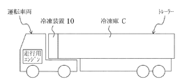
本実施形態の冷凍装置(10)は、図1に示すように、冷凍食品や生鮮食品等を陸上輸送する冷凍車に用いられる。この冷凍車は、運転室や走行用エンジンが設けられた運転車両(トレーラーヘッド)と、冷凍庫(C)が設けられた荷台車両(トレーラー)とが切り離し自在に連結されている。そして、本実施形態に係る冷凍装置(10)は、荷台車両(トレーラー)の前方側に設けられ、冷凍庫(C)内を冷却するためのものである。 As shown in FIG. 1, the refrigeration apparatus (10) of this embodiment is used in a refrigeration vehicle that transports frozen foods, fresh foods, and the like on land. In this refrigeration vehicle, a driving vehicle (trailer head) provided with a driver's cab and a traveling engine and a cargo carrier vehicle (trailer) provided with a freezer (C) are detachably connected. And the freezing apparatus (10) which concerns on this embodiment is provided in the front side of a carrier vehicle (trailer), and is for cooling the inside of a freezer (C).
図2および図3に示すように、上記冷凍装置(10)は、発電用エンジン(21)と、発電機(22)と、コンバータ(23)と、3つのインバータ(24,25,26)と、冷媒回路(30)とを備えている。 As shown in FIGS. 2 and 3, the refrigeration apparatus (10) includes a power generation engine (21), a generator (22), a converter (23), and three inverters (24, 25, 26). And a refrigerant circuit (30).
上記発電機(22)は、発電用エンジン(21)に接続され、該発電用エンジン(21)の動力によって発電する。上記発電用エンジン(21)は、運転車両の走行用エンジンとは別に設けられた冷凍装置専用のものである。そして、この発電用エンジン(21)は、電子ガバナ制御により燃料供給量が調節されることによって運転回転数が制御される。 The generator (22) is connected to a power generation engine (21) and generates power using the power of the power generation engine (21). The power generation engine (21) is dedicated to the refrigeration system provided separately from the traveling engine of the operating vehicle. The power generation engine (21) is controlled in operating speed by adjusting the fuel supply amount by electronic governor control.
上記コンバータ(23)は、発電機(22)と電気的に接続され、該発電機(22)で発電された交流電力を直流電力に変換するためのものである。上記3つのインバータ(24,25,26)は、コンバータ(23)に対して並列に電気的に接続され、該コンバータ(23)の直流電力を交流電力に変換するためのものである。 The converter (23) is electrically connected to the generator (22) and converts AC power generated by the generator (22) into DC power. The three inverters (24, 25, 26) are electrically connected in parallel to the converter (23), and convert the DC power of the converter (23) into AC power.
具体的に、第1インバータ(24)は、後述する冷媒回路(30)の電動圧縮機(31)のモータに交流電力を出力し、該電動圧縮機(31)を駆動するように構成されている。第2インバータ(25)は、後述する冷媒回路(30)の凝縮器ファン(35)のモータに交流電力を出力し、該凝縮器ファン(35)を駆動するように構成されている。第3インバータ(26)は、後述する冷媒回路(30)の蒸発器ファン(36)のモータに交流電力を出力し、該蒸発器ファン(36)を駆動するように構成されている。 Specifically, the first inverter (24) is configured to output AC power to a motor of an electric compressor (31) of the refrigerant circuit (30) described later and drive the electric compressor (31). Yes. The second inverter (25) is configured to output AC power to the motor of the condenser fan (35) of the refrigerant circuit (30), which will be described later, and to drive the condenser fan (35). The third inverter (26) is configured to output AC power to a motor of an evaporator fan (36) of the refrigerant circuit (30) described later to drive the evaporator fan (36).
つまり、本実施形態において、コンバータ(23)およびインバータ(24,25,26)は、電力変換装置を構成している。 That is, in this embodiment, the converter (23) and the inverters (24, 25, 26) constitute a power converter.
上記冷媒回路(30)は、電動圧縮機(31)、凝縮器(32)、電子膨張弁(33)および蒸発器(34)が順に配管接続されている。上記凝縮器(32)の近傍には凝縮器ファン(35)が、上記蒸発器(34)の近傍には蒸発器ファン(36)がそれぞれ設けられている。 In the refrigerant circuit (30), an electric compressor (31), a condenser (32), an electronic expansion valve (33) and an evaporator (34) are connected in order by piping. A condenser fan (35) is provided in the vicinity of the condenser (32), and an evaporator fan (36) is provided in the vicinity of the evaporator (34).
上記電動圧縮機(31)は、スクロール式の圧縮機である。上記凝縮器ファン(35)は庫外空気を凝縮器(32)へ取り込み、上記蒸発器ファン(36)は庫内空気を蒸発器(34)へ取り込む。上記冷媒回路(30)は、冷媒が循環して蒸気圧縮式冷凍サイクルを行うように構成されている。つまり、上記凝縮器(32)で凝縮した液冷媒が、電子膨張弁(33)で減圧された後、蒸発器(34)で庫内空気と熱交換して蒸発し、庫内空気が冷却される。 The electric compressor (31) is a scroll type compressor. The condenser fan (35) takes outside air into the condenser (32), and the evaporator fan (36) takes inside air into the evaporator (34). The refrigerant circuit (30) is configured to perform a vapor compression refrigeration cycle by circulating the refrigerant. That is, the liquid refrigerant condensed in the condenser (32) is depressurized by the electronic expansion valve (33) and then evaporated by exchanging heat with the internal air in the evaporator (34) to cool the internal air. The
上記冷凍装置(10)には、発電用エンジン(21)の運転回転数を検出するための回転数検出部(28)が設けられている。 The refrigeration apparatus (10) is provided with a rotation speed detection unit (28) for detecting the operation rotation speed of the power generation engine (21).
上記発電機(22)とコンバータ(23)との間には、切換スイッチ(27)が設けられている。この切換スイッチ(27)は、コンバータ(23)が発電機(22)に繋がる状態と商用電源に繋がる状態とに切り換えるように構成されている。例えば、冷凍車が長時間停止する場合、発電用エンジン(21)を停止し、コンバータ(23)と商用電源とが繋がるように切換スイッチ(27)を切り換える。 A changeover switch (27) is provided between the generator (22) and the converter (23). The changeover switch (27) is configured to switch between a state where the converter (23) is connected to the generator (22) and a state where it is connected to a commercial power source. For example, when the refrigerator is stopped for a long time, the power generation engine (21) is stopped, and the changeover switch (27) is switched so that the converter (23) and the commercial power supply are connected.
上記冷凍装置(10)は、制御装置(40)(制御手段)を備えている。この制御装置(40)は、冷凍機器制御部(41)と、エンジン制御部(42)と、回転数制御部(43)と、圧縮機異常検知部(44)と、エンジン異常検知部(45)と、ファン異常検知部(46)とを有している。 The refrigeration apparatus (10) includes a control device (40) (control means). The control device (40) includes a refrigeration equipment control unit (41), an engine control unit (42), a rotation speed control unit (43), a compressor abnormality detection unit (44), and an engine abnormality detection unit (45 ) And a fan abnormality detection unit (46).
上記冷凍機器制御部(41)は、冷凍庫(C)内の温度(庫内温度)が入力され、その庫内温度と目標温度とに基づき必要冷凍能力を設定するように構成されている。そして、上記冷凍機器制御部(41)は、必要冷凍能力に基づいて、各インバータ(24,25,26)の出力電力を個別に制御すると共に、電子膨張弁(33)の開度を制御するように構成されている。つまり、上記冷凍機器制御部(41)は、電動圧縮機(31)およびファン(35,36)のそれぞれが最適効率で駆動するように個別に能力制御する。 The said refrigeration equipment control part (41) is comprised so that the temperature (internal temperature) in a freezer (C) may be input and required refrigerating capacity may be set based on the internal temperature and target temperature. And the said refrigeration equipment control part (41) controls the opening degree of an electronic expansion valve (33) while controlling the output electric power of each inverter (24,25,26) separately based on required refrigerating capacity. It is configured as follows. That is, the refrigeration equipment control unit (41) individually controls the capacity so that the electric compressor (31) and the fans (35, 36) are driven with optimum efficiency.
なお、上記冷凍機器制御部(41)は、外気温、電動圧縮機(31)の吐出管温度、冷媒の凝縮温度Tcおよび蒸発温度Teも加味して、各インバータ(24,25,26)や電子膨張弁(33)を制御している。 The refrigeration equipment control unit (41) includes the inverter (24, 25, 26), the outside air temperature, the discharge pipe temperature of the electric compressor (31), the refrigerant condensation temperature Tc, and the evaporation temperature Te. The electronic expansion valve (33) is controlled.
上記冷凍機器制御部(41)は、通常制御モード、高精度制御モードおよびファン間欠制御モードの3つの運転制御モードを備えている。 The refrigeration equipment control unit (41) has three operation control modes: a normal control mode, a high-precision control mode, and a fan intermittent control mode.
上記通常制御モードでは、電動圧縮機(31)および各ファン(35,36)のそれぞれが最適効率で駆動するように、各インバータ(24,25,26)が制御されるようになっている。 In the normal control mode, each inverter (24, 25, 26) is controlled so that each of the electric compressor (31) and each fan (35, 36) is driven with optimum efficiency.
上記高精度制御モードでは、電動圧縮機(31)の回転数が固定され、各ファン(35,36)の回転数のみが制御されるようになっている。つまり、上記第1インバータ(24)の出力電力は変化せずに、第2インバータ(25)および第3インバータ(26)の出力電力のみが制御される。 In the high precision control mode, the rotation speed of the electric compressor (31) is fixed, and only the rotation speed of each fan (35, 36) is controlled. That is, only the output power of the second inverter (25) and the third inverter (26) is controlled without changing the output power of the first inverter (24).
上記ファン間欠制御モードでは、必要冷凍能力に関係なく、ファン(35,36)が低回転数と高回転数で繰り返して駆動するように、第2インバータ(25)および第3インバータ(26)の出力電力が制御されるようになっている。 In the fan intermittent control mode, the second inverter (25) and the third inverter (26) are driven so that the fans (35, 36) are repeatedly driven at a low speed and a high speed regardless of the necessary refrigeration capacity. The output power is controlled.
上記エンジン制御部(42)は、各インバータ(24,25,26)の出力電力状態が入力される。そして、上記エンジン制御部(42)は、入力された出力電力に基づいて、発電用エンジン(21)の燃料消費率および発電機(22)の運転効率が最小値となるエンジン回転数を導出するように構成されている。 The engine control unit (42) receives the output power state of each inverter (24, 25, 26). Then, the engine control unit (42) derives the engine speed at which the fuel consumption rate of the generator engine (21) and the operating efficiency of the generator (22) are minimum values based on the input output power. It is configured as follows.
また、上記エンジン制御部(42)は、通常制御モード、低騒音制御モードの2つの運転制御モードを備えている。 The engine control unit (42) has two operation control modes, a normal control mode and a low noise control mode.
上記通常制御モードでは、発電用エンジン(21)の許容最大回転数を上限として駆動されるモードである。上記低騒音制御モードは、発電用エンジン(21)が許容最大回転数よりも低い所定回転数を上限として駆動されるモードである。つまり、発電用エンジン(21)は、高回転数で駆動すると騒音値が高くなる。したがって、回転数の上限値を下げることにより、低回転数で駆動されるようになるので、騒音値が低下させることができる。 The normal control mode is a mode driven with the maximum allowable number of revolutions of the power generation engine (21) as an upper limit. The low noise control mode is a mode in which the power generation engine (21) is driven with a predetermined rotational speed lower than the allowable maximum rotational speed as an upper limit. That is, when the power generation engine (21) is driven at a high rotational speed, the noise value becomes high. Therefore, by lowering the upper limit value of the rotational speed, the engine is driven at a low rotational speed, so that the noise value can be reduced.
上記回転数制御部(43)は、エンジン制御部(42)で導出したエンジン回転数が入力される。そして、上記回転数制御部(43)は、入力された回転数で発電用エンジン(21)が駆動するように、電子ガバナ制御によって発電用エンジン(21)の燃料供給量を調節するように構成されている。 The engine speed derived from the engine controller (42) is input to the engine speed controller (43). The rotational speed control unit (43) is configured to adjust the fuel supply amount of the power generation engine (21) by electronic governor control so that the power generation engine (21) is driven at the input rotational speed. Has been.
このように、本冷凍装置(10)では、発電機(22)と各冷凍機器との間に電力変換装置としてのコンバータ(23)およびインバータ(24,25,26)を接続するようにしたので、発電用エンジン(21)の回転数と、電動圧縮機(31)等の回転数とを個別に制御することができる。この結果、発電用エンジン(21)や電動圧縮機(31)をそれぞれ最適な効率で駆動することができる。 Thus, in this refrigeration apparatus (10), the converter (23) and the inverter (24, 25, 26) as the power conversion apparatus are connected between the generator (22) and each refrigeration equipment. The number of revolutions of the power generation engine (21) and the number of revolutions of the electric compressor (31) can be individually controlled. As a result, the power generation engine (21) and the electric compressor (31) can be driven with optimum efficiency.
また、上記冷凍機器制御部(41)が電動圧縮機(31)を最大回転数で駆動する場合、エンジン制御部(42)は、発電用エンジン(21)の回転数が上記電動圧縮機(31)の最大回転数よりも低くなるように上記発電用エンジン(21)を制御するように構成されている。また、上記冷凍機器制御部(41)が電動圧縮機(31)を最小回転数で駆動する場合、エンジン制御部(42)は、発電用エンジン(21)の回転数が上記電動圧縮機(31)の最小回転数よりも高くなるように上記発電用エンジン(21)を制御するように構成されている。 Further, when the refrigeration equipment control unit (41) drives the electric compressor (31) at the maximum rotational speed, the engine control unit (42) is configured so that the rotational speed of the power generation engine (21) is the electric compressor (31 ), The power generation engine (21) is controlled to be lower than the maximum rotational speed. Further, when the refrigeration equipment control unit (41) drives the electric compressor (31) at the minimum rotational speed, the engine control unit (42) is configured such that the rotational speed of the power generation engine (21) is the electric compressor (31 The generator engine (21) is controlled to be higher than the minimum number of revolutions).
上記圧縮機異常検知部(44)は、第1インバータ(24)の出力電力、つまり出力電流および出力電圧に基づいて電動圧縮機(31)の異常状態を検知するように構成されている。具体的に、上記圧縮機異常検知部(44)は、電流および電圧から電動圧縮機(31)の発生トルクTを推定し、その発生トルクTに基づいて、電動圧縮機(31)が故障したか、故障する前(故障寸前)かを判定する。 The compressor abnormality detection unit (44) is configured to detect an abnormal state of the electric compressor (31) based on output power of the first inverter (24), that is, output current and output voltage. Specifically, the compressor abnormality detection unit (44) estimates the generated torque T of the electric compressor (31) from the current and voltage, and the electric compressor (31) has failed based on the generated torque T. Or before failure (immediately before failure).
上記圧縮機異常検知部(44)において電動圧縮機(31)が故障と判定されると、冷凍機器制御部(41)が電動圧縮機(31)を停止するようになっている。なお、発電用エンジン(21)については場合によって停止させる。また、上記圧縮機異常検知部(44)において電動圧縮機(31)が故障する前と判定されると、電動圧縮機(31)は停止せずに回転数が所定値で固定されるように、冷凍機器制御部(41)が第1インバータ(24)を制御するようになっている(以下、圧縮機延命運転という)。なお、冷凍機器制御部(41)は、圧縮機延命運転を行うと共に、メンテナンス要求を操作表示盤等に表示させる。 When the compressor abnormality detector (44) determines that the electric compressor (31) is out of order, the refrigeration equipment controller (41) stops the electric compressor (31). The power generation engine (21) is stopped depending on circumstances. In addition, when the compressor abnormality detection unit (44) determines that the electric compressor (31) is before failure, the electric compressor (31) is not stopped and the rotation speed is fixed at a predetermined value. The refrigeration equipment control unit (41) controls the first inverter (24) (hereinafter referred to as compressor life extension operation). The refrigeration equipment control unit (41) performs a life extension operation of the compressor and displays a maintenance request on an operation display panel or the like.
また、上記圧縮機異常検知部(44)は、第1インバータ(24)の出力電流および出力電圧から電動圧縮機(31)のモータの巻き線抵抗Rを推定し、その巻き線抵抗Rに基づいて、電動圧縮機(31)が故障したか、故障する前(故障寸前)かを判定するようにしてもよい。なお、モータの巻き線抵抗Rはモータの温度に比例するため、電動圧縮機(31)の過熱状態が推定されることになる。 The compressor abnormality detection unit (44) estimates the winding resistance R of the motor of the electric compressor (31) from the output current and output voltage of the first inverter (24), and based on the winding resistance R. Thus, it may be determined whether the electric compressor (31) has failed or before failure (immediately before the failure). Since the winding resistance R of the motor is proportional to the temperature of the motor, the overheated state of the electric compressor (31) is estimated.
また、上記圧縮機異常検知部(44)は、第1インバータ(24)の出力電流および出力電圧から電動圧縮機(31)のモータ磁石の磁束Ψを推定し、その磁束Ψに基づいて、電動圧縮機(31)が故障したか、故障する前(故障寸前)かを判定するようにしてもよい。 The compressor abnormality detector (44) estimates the magnetic flux Ψ of the motor magnet of the electric compressor (31) from the output current and output voltage of the first inverter (24), and based on the magnetic flux Ψ, It may be determined whether the compressor (31) has failed or before it has failed (immediately before the failure).
上記エンジン異常検知部(45)は、発電用エンジン(21)の燃料供給量に基づいて該発電用エンジン(21)の異常状態を検知するように構成されている。つまり、上記エンジン異常検知部(45)は、実際の燃料供給量と正常運転時のものとの関係から、発電用エンジン(21)が故障したか、故障する前(故障寸前)かを判定する。 The engine abnormality detection unit (45) is configured to detect an abnormal state of the power generation engine (21) based on the fuel supply amount of the power generation engine (21). In other words, the engine abnormality detection unit (45) determines whether the power generation engine (21) has failed or has failed (immediately before the failure) from the relationship between the actual fuel supply amount and that during normal operation. .
上記エンジン異常検知部(45)において発電用エンジン(21)が故障と判定されると、冷凍機器制御部(41)が電動圧縮機(31)およびファン(35,36)を、エンジン制御部(42)が発電用エンジン(21)をそれぞれ停止するようになっている。また、上記エンジン異常検知部(45)において発電用エンジン(21)が故障する前と判定されると、発電用エンジン(21)は停止せずに該発電用エンジン(21)の負荷が低減されるように、冷凍機器制御部(41)が電動圧縮機(31)およびファン(35,36)の少なくとも一方の回転数を制御するようになっている(以下、エンジン延命運転という)。なお、冷凍機器制御部(41)は、エンジン延命運転を行うと共に、メンテナンス要求を操作表示盤等に表示させる。 When it is determined in the engine abnormality detection unit (45) that the power generation engine (21) has failed, the refrigeration equipment control unit (41) replaces the electric compressor (31) and the fans (35, 36) with the engine control unit ( 42) stops the generator engine (21). If the engine abnormality detection unit (45) determines that the power generation engine (21) has not failed, the power generation engine (21) is not stopped and the load on the power generation engine (21) is reduced. As described above, the refrigeration equipment controller (41) controls the rotational speed of at least one of the electric compressor (31) and the fan (35, 36) (hereinafter referred to as engine life extension operation). The refrigeration equipment control unit (41) performs engine life extension operation and displays a maintenance request on an operation display panel or the like.
上記ファン異常検知部(46)は、凝縮器ファン(35)であれば第2インバータ(25)の出力電力、蒸発器ファン(36)であれば第3インバータ(26)の出力電力、つまり出力電流および出力電圧に基づいてファン(35,36)の異常状態を検知するように構成されている。具体的に、上記ファン異常検知部(46)は、電流および電圧からファン(35,36)の発生トルクTを推定し、その発生トルクTに基づいて、ファン(35,36)が故障したか、故障する前(故障寸前)かを判定する。 The fan abnormality detection unit (46) outputs the output power of the second inverter (25) if the condenser fan (35), or the output power of the third inverter (26) if the evaporator fan (36). An abnormal state of the fan (35, 36) is detected based on the current and the output voltage. Specifically, the fan abnormality detection unit (46) estimates the generated torque T of the fan (35, 36) from the current and voltage, and whether the fan (35, 36) has failed based on the generated torque T. Determine whether it is before failure (immediately before failure).
上記ファン異常検知部(46)においてファン(35,36)が故障と判定されると、冷凍機器制御部(41)がファン(35,36)を停止するようになっている。なお、発電用エンジン(21)については場合によって停止させる。また、上記ファン異常検知部(46)においてファン(35,36)が故障する前と判定されると、ファン(35,36)は停止せずに回転数が所定値で固定されるように、冷凍機器制御部(41)が各インバータ(25,26)を制御するようになっている(以下、ファン延命運転という)。なお、冷凍機器制御部(41)は、ファン延命運転を行うと共に、メンテナンス要求を操作表示盤等に表示させる。 When the fan abnormality detection unit (46) determines that the fan (35, 36) is out of order, the refrigeration equipment control unit (41) stops the fan (35, 36). The power generation engine (21) is stopped depending on circumstances. In addition, when it is determined in the fan abnormality detection unit (46) that the fan (35, 36) has failed, the fan (35, 36) does not stop and the rotational speed is fixed at a predetermined value. The refrigeration equipment controller (41) controls each inverter (25, 26) (hereinafter referred to as fan life extension operation). The refrigeration equipment control unit (41) performs a fan life extension operation and displays a maintenance request on an operation display panel or the like.
−運転動作−
次に、本実施形態の冷凍装置(10)の運転動作について説明する。
-Driving action-
Next, the operation of the refrigeration apparatus (10) of this embodiment will be described.
先ず、発電用エンジン(21)が駆動されると、その動力によって発電機(22)が発電する。発電した交流電力は、コンバータ(23)で直流電力に変換されて各インバータ(24,25,26)へ出力される。各インバータ(24,25,26)では、直流電力が再び交流電力に変換されて電動圧縮機(31)およびファン(35,36)へ出力される。これにより、電動圧縮機(31)および各ファン(35,36)が駆動し、冷媒回路(30)にて蒸気圧縮式冷凍サイクルが行われる。 First, when the power generation engine (21) is driven, the power generator (22) generates power using the power. The generated AC power is converted into DC power by the converter (23) and output to each inverter (24, 25, 26). In each inverter (24, 25, 26), DC power is again converted into AC power and output to the electric compressor (31) and the fan (35, 36). Thereby, the electric compressor (31) and the fans (35, 36) are driven, and the vapor compression refrigeration cycle is performed in the refrigerant circuit (30).
上記の運転状態において、冷凍機器制御部(41)によって各インバータ(24,25,26)が個別に制御されて、電動圧縮機(31)および各ファン(35,36)が制御される。一方、上記エンジン制御部(42)によって、電動圧縮機(31)および各ファン(35,36)の回転数とは無関係に発電用エンジン(21)の回転数が制御される。 In the above operating state, the inverter (24, 25, 26) is individually controlled by the refrigeration equipment controller (41), and the electric compressor (31) and the fans (35, 36) are controlled. On the other hand, the engine control unit (42) controls the rotational speed of the power generation engine (21) regardless of the rotational speeds of the electric compressor (31) and the fans (35, 36).
具体的に、電動圧縮機(31)および各ファン(35,36)が冷凍機器制御部(41)によって導出された必要冷凍能力に見合う回転数でそれぞれ駆動するように各インバータ(24,25,26)が制御される。また、各ファン(35,36)は、負荷率が同じ場合、回転数をできるだけ下げるように制御される。図7に示すように、負荷率が同じ場合、ファン(35,36)は回転数を下げて風量を減少させても、蒸発器(34)における熱交換量、すなわち庫内へ供給される冷凍能力は変化しないことが分かる。つまり、回転数を下げることで、必要電流が低下するので省エネに繋がる。その際、吹出温度は低下することになるが、庫内温度には殆ど影響しない。 Specifically, the electric compressor (31) and the fans (35, 36) are driven by the inverters (24, 25,) so as to be driven at a rotational speed corresponding to the necessary refrigeration capacity derived by the refrigeration equipment controller (41). 26) is controlled. Each fan (35, 36) is controlled so as to reduce the rotational speed as much as possible when the load factor is the same. As shown in FIG. 7, when the load factor is the same, even if the fans (35, 36) reduce the rotational speed and reduce the air volume, the heat exchange amount in the evaporator (34), that is, the refrigeration supplied into the warehouse It turns out that ability does not change. That is, by reducing the rotation speed, the required current is reduced, which leads to energy saving. At that time, the blowing temperature is lowered, but it hardly affects the internal temperature.
上記エンジン制御部(42)では、各インバータ(24,25,26)の出力電力状態からその負荷率を算出し、その負荷状態で燃料消費率が最低となるエンジン回転数を、図4に基づいて導出する。 In the engine control unit (42), the load factor is calculated from the output power state of each inverter (24, 25, 26), and the engine speed at which the fuel consumption rate is the lowest in the load state is calculated based on FIG. To derive.
例えば、定格出力状態(1700rpm,10kW)で冷凍制御が行われている状態において、庫内温度の目標温度が大きく下げられた場合、次のような動作となる。庫内温度が目標温度に対して大きく離れているため、冷凍機器制御部(41)は最大の冷却能力を発生すべく各インバータに指令が出す。その結果、消費電力は大きくなり、コンバータはそれに見合う電力を供給すべく発電機(22)から電力を取り出す。その結果、発電用エンジン(21)は負荷トルクが大きくなり、そのままの燃料噴射量ではエンジン回転数が低下していくため、エンジン回転数制御部(43)は指令されているエンジン回転数を保持すべく、燃料噴射量を増加させる。 For example, in the state where the refrigeration control is performed in the rated output state (1700 rpm, 10 kW), when the target temperature of the internal temperature is greatly lowered, the following operation is performed. Since the internal temperature is far away from the target temperature, the refrigeration equipment control unit (41) issues a command to each inverter to generate the maximum cooling capacity. As a result, power consumption increases, and the converter extracts power from the generator (22) in order to supply power commensurate with it. As a result, the engine for power generation (21) has an increased load torque, and the engine speed decreases at the same fuel injection amount. Therefore, the engine speed controller (43) maintains the commanded engine speed. Therefore, the fuel injection amount is increased.
例えば、その負荷が14kWで負荷率140%に相当する場合、図4によれば、1700rpmと140%の負荷ラインが交差するポイントの燃料消費率(約1.08)が読み取れる。ここで、負荷率140%のラインに着目すると、その燃料消費率が一番底となっているのは、約2100rpm以上で約1.05あることが分かるので、回転数制御部(43)へのエンジン回転数指令として2100rpmを指令する。結果、0.03の燃費向上を見込むことができる。140%負荷率では2100rpm以上はほぼ同じ燃料消費率であるが、高速回転にするとエンジン音が大きくなるなどが懸念されるため、同じ燃料消費率であるならエンジン回転数は低いほうを選択するほうが良い。 For example, when the load is 14 kW and corresponds to a load factor of 140%, according to FIG. 4, the fuel consumption rate (about 1.08) at the point where 1700 rpm and the load line of 140% intersect can be read. Here, paying attention to the line with a load factor of 140%, it can be seen that the fuel consumption rate is at the bottom of about 1.05 at about 2100 rpm or higher, so the engine to the rotation speed control unit (43) Command 2100rpm as the rotational speed command. As a result, a fuel efficiency improvement of 0.03 can be expected. At a load factor of 140%, the fuel consumption rate is almost the same at 2100 rpm or higher, but there is a concern that the engine noise will increase at high speeds, so if the fuel consumption rate is the same, it is better to select the lower engine speed. good.
また、庫内の冷却が十分に行われ、外部からの壁面などを経由しての熱量負荷のみとなった場合、電動圧縮機(31)およびファン(35,36)が必要とする電力は低下する。この場合、上記と同様に負荷率が軽い場合の燃料賞比率はエンジン回転数が低いほうが良いことが見て取れ、エンジン回転数を低いほうに設定することで燃料消費率の低減を図ることができる。但し、エンジン回転数には下限制限があるため、その範囲での運転となる。これにより、発電用エンジン(21)を最も省エネな状態で駆動することができる。 In addition, when the inside of the refrigerator is sufficiently cooled and only the heat load is applied via the external wall surface, the power required by the electric compressor (31) and fan (35, 36) is reduced. To do. In this case, it can be seen that the fuel award ratio when the load factor is light as described above is better when the engine speed is lower, and the fuel consumption rate can be reduced by setting the engine speed lower. However, since the engine speed has a lower limit, the engine operates within that range. Thereby, the power generation engine (21) can be driven in the most energy-saving state.
さらに、上記エンジン制御部(42)では、各インバータ(24,25,26)の出力電力状態からその負荷率を算出し、その負荷状態で発電機(22)の効率が最高となる回転数を、図5に基づいて導出する。図5は、発電機(22)の回転数と負荷率に対する発電機効率を示したものである。これによると、発電機(22)の効率は回転数が高いほど良いことが分かる。 Further, the engine control unit (42) calculates the load factor from the output power state of each inverter (24, 25, 26), and determines the rotation speed at which the efficiency of the generator (22) is maximum in the load state. Based on FIG. FIG. 5 shows the generator efficiency with respect to the rotational speed and load factor of the generator (22). According to this, it turns out that the efficiency of a generator (22) is so good that a rotation speed is high.
エンジンのみで見ればエンジン負荷率が軽い場合はエンジン回転数を出来る限り低下させることが効率的に良いが、上記のように発電機の効率特性は回転数が低下するほど悪化する傾向にある。発電機とエンジンは直結またはベルト、ギアなどでの接続となるため、回転数は比例関係となる。これより、ある負荷率においてエンジン〜発電機出力までの効率が最適となるポイントは値が小さいほど良い燃料消費率と、値が大きいほど良い発電機効率の両方を考慮した場合、
総合効率係数 = 発電機効率 ÷ 燃料消費率
が極大になる回転数を求めれば良いことになるのは自明である。この総合効率係数が極大となる回転数を回転数制御部(43)に指令することが発電システムとして最も燃費の良い運転をおこなうことになる。
From the standpoint of the engine alone, when the engine load factor is light, it is efficient to reduce the engine speed as much as possible. However, as described above, the efficiency characteristics of the generator tend to deteriorate as the speed decreases. Since the generator and the engine are directly connected or connected by a belt, gear, etc., the rotational speed is in a proportional relationship. From this, the point at which the efficiency from the engine to the generator output is optimal at a certain load factor is when considering both the better fuel consumption rate as the value is smaller and the better generator efficiency as the value is larger,
It is obvious that the total efficiency factor = generator efficiency ÷ the number of revolutions that maximizes the fuel consumption rate can be obtained. Instructing the rotational speed control unit (43) to the rotational speed at which the total efficiency coefficient is maximized performs the operation with the best fuel efficiency as the power generation system.
また、上記エンジン制御部(42)では、次のような制御も可能である。負荷率が決定した後に、その負荷率において最も省エネとなるエンジン回転数を導出し、その回転数を指令したが、その場合、負荷が増加する方向に変化した場合の発電用エンジン(21)の動作としては、回転数指令が固定された状態において負荷が上昇、回転数指令が固定されているため、その回転数を保持したまま出力を上げるべく燃料消費率が上昇する。その後、先の最も省エネとなる回転数へと移行していくため、図6におけるAのような経路をたどる。 The engine control unit (42) can also perform the following control. After the load factor is determined, the engine speed at which the load factor is the most energy-saving is derived, and the engine speed is commanded. In that case, the power generation engine (21) when the load changes is increased. In terms of operation, the load increases while the rotational speed command is fixed, and the rotational speed command is fixed. Therefore, the fuel consumption rate increases to increase the output while maintaining the rotational speed. Then, in order to shift to the rotational speed at which the most energy is saved, the route shown by A in FIG. 6 is followed.
しかしながら、冷凍機器制御部(41)からの冷凍能力を上げる(結果としてエンジンの負荷率が上昇する)ように動作を進めていることは情報として得ることができ、またその負荷率がどのような傾きであるかも得ることができる。この情報を利用し、発電用エンジン(21)の負荷が変わる前にフィードフォワード的にエンジン回転数指令を上昇させる制御を行うことで、図6におけるBの経路を通り、最終のポイントに行き着くことが可能となる。結果、燃料消費率の悪い経路をたどらなくて良い分、燃費の向上を図ることが可能となる。 However, it can be obtained as information that the operation is progressing so as to increase the refrigeration capacity from the refrigeration equipment controller (41) (resulting in an increase in the engine load factor), and what the load factor is You can also get a tilt. By using this information and performing control to increase the engine speed command in a feed-forward manner before the load of the power generation engine (21) changes, the final point is reached through the path B in FIG. Is possible. As a result, it is possible to improve the fuel consumption because it is not necessary to follow a route with a low fuel consumption rate.
次に、上記圧縮機異常検知部(44)が発生トルクTに基づいて異常状態を判定する流れについて、図8を参照しながら説明する。 Next, the flow in which the compressor abnormality detection unit (44) determines an abnormal state based on the generated torque T will be described with reference to FIG.
上記冷凍装置(10)の運転が開始されると(ステップS11)、ステップS12へ移行して、第1インバータ(24)の出力電流および出力電圧が圧縮機異常検知部(44)へ入力される。ステップS13では、圧縮機異常検知部(44)により、出力電流および出力電圧に基づいて電動圧縮機(31)の発生トルクTが以下の式(1)により算出され、ステップS14へ移行する。
発生トルクT=P×{Ψ0+(Ld−Lq)×id}×iq ・・・式(1)
ここに、P、Ψ0、LdおよびLqはモータ定数を示し、設計値または生産時の計測値である。idおよびiqは、出力電流をdq変換したもので、それぞれd軸電流およびq軸電流を示す。
When the operation of the refrigeration apparatus (10) is started (step S11), the process proceeds to step S12, and the output current and output voltage of the first inverter (24) are input to the compressor abnormality detection unit (44). . In step S13, the generated torque T of the electric compressor (31) is calculated by the compressor abnormality detector (44) based on the output current and output voltage by the following equation (1), and the process proceeds to step S14.
Generated torque T = P × {Ψ0 + (Ld−Lq) × id} × iq Expression (1)
Here, P, Ψ0, Ld, and Lq indicate motor constants, which are design values or measured values during production. id and iq are obtained by dq conversion of the output current, and indicate a d-axis current and a q-axis current, respectively.
ステップS14において、発生トルクTが所定値2より大きいか否かが判断され、大きい場合は、電動圧縮機(31)が故障したと判定されてステップS15へ移行し、発電用エンジン(21)および電動圧縮機(31)が停止される。発生トルクTが所定値2以下である場合、電動圧縮機(31)が故障していないと判定されてステップS16へ移行する。ステップS16において、発生トルクTが所定値1より大きいか否かが判断され、大きい場合は、電動圧縮機(31)が故障する前と判定されてステップS17へ移行し、圧縮機延命運転が行われると共に、メンテナンス要求が操作表示盤等に表示される。発生トルクTが所定値1以下である場合は、電動圧縮機(31)が全く正常であると判定されてステップS11へ戻る。なお、上記所定値1は、通常運転時の正常値より大きく、所定値2より小さい値に設定されている。また、これら所定値は、予め庫内外の温度との関係から定められるたものである。
In step S14, it is determined whether or not the generated torque T is greater than a
上記圧縮機異常検知部(44)が巻き線抵抗Rに基づいて異常状態を判定する流れについて、図9を参照しながら説明する。 A flow in which the compressor abnormality detection unit (44) determines an abnormal state based on the winding resistance R will be described with reference to FIG.
上記冷凍装置(10)の運転が開始されると(ステップS21)、ステップS22へ移行して、第1インバータ(24)の出力電流および出力電圧が圧縮機異常検知部(44)へ入力される。ステップS23では、圧縮機異常検知部(44)により、出力電流および出力電圧に基づいて電動圧縮機(31)のモータの巻き線抵抗R(R=出力電圧/出力電流)が求められ、ステップS24へ移行する。ステップS24において、巻き線抵抗Rと以下の式(2)とにより巻き線温度tが算出され、ステップS25に移行する。
巻き線温度t={(R−R0)/(α×R0)}+t0 ・・・式(2)
ここに、R0は巻き線温度t0の時の巻き線抵抗を示し、αは定数である。
When the operation of the refrigeration apparatus (10) is started (step S21), the process proceeds to step S22, and the output current and output voltage of the first inverter (24) are input to the compressor abnormality detection unit (44). . In step S23, the compressor abnormality detection unit (44) obtains the winding resistance R (R = output voltage / output current) of the motor of the electric compressor (31) based on the output current and the output voltage, and step S24. Migrate to In step S24, the winding temperature t is calculated from the winding resistance R and the following equation (2), and the process proceeds to step S25.
Winding temperature t = {(R−R0) / (α × R0)} + t0 Formula (2)
Here, R0 indicates the winding resistance at the winding temperature t0, and α is a constant.
ステップS25において、巻き線温度tが所定値2より大きいか否かが判断され、大きい場合は、電動圧縮機(31)が故障したと判定されてステップS26へ移行し、発電用エンジン(21)および電動圧縮機(31)が停止される。巻き線温度tが所定値2以下である場合、電動圧縮機(31)が故障していないと判定されてステップS27へ移行する。ステップS27において、巻き線温度tが所定値1より大きいか否かが判断され、大きい場合は、電動圧縮機(31)が故障する前と判定されてステップS28へ移行し、圧縮機延命運転が行われると共に、メンテナンス要求が操作表示盤等に表示される。巻き線温度tが所定値1以下である場合は、電動圧縮機(31)が全く正常であると判定されてステップS21へ戻る。なお、上記所定値1は、通常運転時の正常値より大きく、所定値2より小さい値に設定されている。また、これら所定値は、予め電動圧縮機(31)の吐出管温度との
関係から定められたものである。
In step S25, it is determined whether or not the winding temperature t is greater than a
上記圧縮機異常検知部(44)が磁束Ψに基づいて異常状態を判定する流れについて、図10を参照しながら説明する。 A flow in which the compressor abnormality detection unit (44) determines an abnormal state based on the magnetic flux Ψ will be described with reference to FIG.
上記冷凍装置(10)の運転が開始されると(ステップS31)、ステップS32へ移行する。そして、ステップS32からステップS34における制御内容は、上述した図9のステップS22からステップS24と同様である。つまり、第1インバータ(24)の出力電流および出力電圧に基づいて電動圧縮機(31)のモータの巻き線抵抗Rが算出され、その巻き線抵抗Rに基づいて巻き線温度tが算出される。このように、巻き線温度tが算出されるとステップS35が移行して、巻き線温度tと以下の式(3)とにより電動圧縮機(31)のモータ磁石の磁束Ψが算出され、ステップS35へ移行する。
磁束Ψ=Ψ0+A×t ・・・式(3)
ここに、Ψ0は設計時の磁束値を示し、Aは磁石特性から求められる温度係数を示し、tは巻き線温度を示す。
When the operation of the refrigeration apparatus (10) is started (step S31), the process proceeds to step S32. And the control content in step S32 to step S34 is the same as that of step S22 to step S24 of FIG. 9 mentioned above. That is, the winding resistance R of the motor of the electric compressor (31) is calculated based on the output current and output voltage of the first inverter (24), and the winding temperature t is calculated based on the winding resistance R. . As described above, when the winding temperature t is calculated, the process proceeds to step S35, and the magnetic flux Ψ of the motor magnet of the electric compressor (31) is calculated from the winding temperature t and the following equation (3). The process proceeds to S35.
Magnetic flux Ψ = Ψ0 + A × t Formula (3)
Here, Ψ0 represents the magnetic flux value at the time of design, A represents the temperature coefficient obtained from the magnet characteristics, and t represents the winding temperature.
ステップS35において、磁束Ψが所定値2より小さいか否かが判断され、小さい場合は、電動圧縮機(31)が故障したと判定されてステップS36へ移行し、発電用エンジン(21)および電動圧縮機(31)が停止される。磁束Ψが所定値2以上である場合、電動圧縮機(31)が故障していないと判定されてステップS37へ移行する。ステップS37において、磁束Ψが所定値1より小さいか否かが判断され、小さい場合は、電動圧縮機(31)が故障する前と判定されてステップS38へ移行し、圧縮機延命運転が行われると共に、メンテナンス要求が操作表示盤等に表示される。磁束Ψが所定値1以上である場合は、電動圧縮機(31)が全く正常であると判定されてステップS31へ戻る。なお、上記所定値1は、通常運転時の正常値より小さく、所定値2より大きい値に設定されている。また、これら所定値は、予め電動圧縮機(31)の吐出管温度との関係から定められたものである。
In step S35, it is determined whether or not the magnetic flux Ψ is smaller than the
次に、上記エンジン異常検知部(45)が燃料消費量(燃料供給量)に基づいて異常状態を判定する流れについて、図11を参照しながら説明する。 Next, the flow in which the engine abnormality detection unit (45) determines an abnormal state based on the fuel consumption (fuel supply amount) will be described with reference to FIG.
上記冷凍装置(10)の運転が開始されると(ステップS41)、ステップS42へ移行して、発電機(22)の出力電圧がエンジン異常検知部(45)に入力される。なお、ここではコンバータ(23)の入力電流および入力電圧を入力してもよい。ステップS43において、回転数制御部(43)の電子ガバナより燃料消費量がエンジン異常検知部(45)へ入力される。 When the operation of the refrigeration apparatus (10) is started (step S41), the process proceeds to step S42, and the output voltage of the generator (22) is input to the engine abnormality detection unit (45). Here, the input current and the input voltage of the converter (23) may be input. In step S43, the fuel consumption is input from the electronic governor of the rotation speed control unit (43) to the engine abnormality detection unit (45).
ステップS44では、エンジン異常検知部(45)により、燃料消費量が所定値2より大きいか否かが判断され、大きい場合は、発電用エンジン(21)が故障したと判定されてステップS44へ移行し、発電用エンジン(21)および電動圧縮機(31)が停止される。燃料消費量が所定値2以下である場合、発電用エンジン(21)が故障していないと判定されてステップS45へ移行する。ステップS45において、燃料消費量が所定値1より大きいか否かが判断され、大きい場合は、発電用エンジン(21)が故障する前と判定されてステップS46へ移行し、エンジン延命運転が行われると共に、メンテナンス要求が操作表示盤等に表示される。燃料消費量が所定値1以下である場合は、発電用エンジン(21)が全く正常であると判定されてステップS41へ戻る。なお、上記所定値1は、通常運転時の正常値より大きく、所定値2より小さい値に設定されている。また、これら所定値は、ステップS42で入力された発電機(22)の出力電圧との関係から予め定められたものである。
In step S44, the engine abnormality detection unit (45) determines whether or not the fuel consumption is larger than a
また、上記ファン異常検知部(46)において、圧縮機異常検知部(44)と同様の異常検知方法でファン(35,36)の異常判定が行われる。例えば、ファン(35,36)のモータの発生トルクTが所定値2より大きいか否かが判断され、大きい場合は、ファン(35,36)が故障したと判定されて、発電用エンジン(21)およびファン(35,36)が停止される。発生トルクTが所定値2以下である場合、ファン(35,36)が故障していないと判定され、続いて、発生トルクTが所定値1より大きいか否かが判断される。そして、所定値1より大きい場合は、ファン(35,36)が故障する前と判定されて、ファン延命運転が行われると共に、メンテナンス要求が操作表示盤等に表示される。発生トルクTが所定値1以下である場合は、ファン(35,36)が全く正常であると判定されて制御が終了する。
In the fan abnormality detection unit (46), the fan (35, 36) is determined to be abnormal by the same abnormality detection method as the compressor abnormality detection unit (44). For example, it is determined whether or not the generated torque T of the motor of the fan (35, 36) is larger than a
次に、上述した通常制御モード以外の制御モードについて説明する。 Next, control modes other than the above-described normal control mode will be described.
低騒音制御モードが選択されると、エンジン制御部(42)は、上述した発電用エンジン(21)の燃費が悪くなるポイントであっても、許容最大回転数よりも低い所定の回転数以下で発電用エンジン(21)を駆動する。これにより、省エネ運転よりも低騒音の運転を優先して駆動させることができる。 When the low-noise control mode is selected, the engine control unit (42) is not more than a predetermined number of revolutions lower than the allowable maximum number of revolutions, even at the point where the fuel efficiency of the power generation engine (21) described above deteriorates. Power generation engine (21) is driven. As a result, it is possible to drive with low noise driving preferentially over energy saving driving.
高精度制御モードが選択されると、冷凍機器制御部(41)は、庫内温度が目標温度に達した場合、電動圧縮機(31)の回転数を固定し、ファン(35,36)の回転数のみを熱負荷の変動に応じて制御する。これにより、電動圧縮機(31)のみで温度制御を行う場合に比べて、高応答且つ高精度の温度制御を行うことができる。すなわち、庫内温度が目標温度に達した後は、冷凍庫(C)の外壁等からの熱伝導による熱負荷に対応するだけでよいことになる。ここで、電動圧縮機(31)の回転数を制御しても、各部の熱時定数の分だけ能力変化の応答性が低いため、急激に回転数を変化させようとすると、いわゆるハッチング現象が生じてしまう。これに対し、ファン(35,36)制御の場合、特別な熱時定数が存在しないため、調節した回転数の分だけ割と早く能力変化として表れる。 When the high-precision control mode is selected, the refrigeration equipment control unit (41) fixes the rotational speed of the electric compressor (31) when the internal temperature reaches the target temperature, and the fan (35, 36) Only the rotation speed is controlled according to the fluctuation of the heat load. Thereby, compared with the case where temperature control is performed only by the electric compressor (31), temperature control with high response and high accuracy can be performed. That is, after the internal temperature reaches the target temperature, it is only necessary to cope with the heat load due to heat conduction from the outer wall of the freezer (C). Here, even if the number of revolutions of the electric compressor (31) is controlled, the responsiveness of the change in capacity is low by the thermal time constant of each part. It will occur. On the other hand, in the case of fan (35, 36) control, since there is no special thermal time constant, the capacity change appears as early as the adjusted number of revolutions.
ファン間欠制御モードが選択されると、冷凍機器制御部(41)は、ファン(35,36)に対して所定の低回転数と高回転数とで交互に駆動されるように制御する。具体的に、ファン(35,36)の風量を最低風量と、トレーラーの奥まで送り届け得る大風量とを繰り返す。これにより、冷凍庫(C)内に乱流を発生させることができ、庫内の温度分布を均一にすることができる。 When the fan intermittent control mode is selected, the refrigeration equipment controller (41) controls the fans (35, 36) to be driven alternately at a predetermined low speed and high speed. Specifically, the air volume of the fans (35, 36) is repeated with the minimum air volume and the large air volume that can be sent to the back of the trailer. Thereby, a turbulent flow can be generated in the freezer (C) and the temperature distribution in the refrigerator can be made uniform.
−実施形態の効果−
以上説明したように、この実施形態によれば、発電用エンジン(21)と電動圧縮機(31)とファン(35,36)とを別個独立に制御できるようにしたので、発電用エンジン(21)を電動圧縮機(31)やファン(35,36)の回転数に連動させて駆動させなくてもよい。したがって、例えば低回転高トルクで発電用エンジン(21)を駆動しなくてもよいため、発電用エンジン(21)の排気量を無駄に大きくする必要がなくなる。この結果、発電用エンジン(21)の小型化および軽量化を図ることができる。
-Effect of the embodiment-
As described above, according to this embodiment, since the power generation engine (21), the electric compressor (31), and the fans (35, 36) can be controlled separately, the power generation engine (21 ) May not be driven in conjunction with the rotational speed of the electric compressor (31) or the fan (35, 36). Therefore, for example, since it is not necessary to drive the power generation engine (21) with low rotation and high torque, there is no need to unnecessarily increase the displacement of the power generation engine (21). As a result, the power generation engine (21) can be reduced in size and weight.
また、電動圧縮機(31)等とは関係なく発電用エンジン(21)にとって最適効率となる回転数で該発電用エンジン(21)を駆動することができる。この結果、装置の省エネ化を図ることができる。 Further, regardless of the electric compressor (31) or the like, the power generation engine (21) can be driven at a rotational speed that is optimal for the power generation engine (21). As a result, energy saving of the apparatus can be achieved.
また、コンバータ(23)を発電機(22)から切り換えて商用電源と繋げるようにしたので、例えば冷凍車が長時間走行停止するような場合、発電用エンジン(21)を駆動させる必要がなくなる。この結果、発電用エンジン(21)の省エネ化を図ることができる。 Further, since the converter (23) is switched from the generator (22) and connected to the commercial power supply, for example, when the refrigeration vehicle stops running for a long time, it is not necessary to drive the power generation engine (21). As a result, energy saving of the power generation engine (21) can be achieved.
また、電動圧縮機(31)や発電用エンジン(21)の故障寸前の異常状態を検知することができる。そして、検知されると、電動圧縮機(31)等の負担を軽減するようにしたので、交換の時期までできるだけ長く運転を持続させることができる。 Further, it is possible to detect an abnormal state immediately before a failure of the electric compressor (31) or the power generation engine (21). When detected, the load on the electric compressor (31) and the like is reduced, so that the operation can be continued as long as possible until the replacement time.
《その他の実施形態》
例えば、上記電動圧縮機(31)としてスクロール式の圧縮機を用いたが、ロータリー式のもの、また往復動式(いわゆる、レシプロ式)のものを用いるようにしてもよい。
<< Other Embodiments >>
For example, although a scroll type compressor is used as the electric compressor (31), a rotary type or a reciprocating type (so-called reciprocating type) may be used.
なお、以上の実施形態および変形例は、本質的に好ましい例示であって、本発明、その適用物、あるいはその用途の範囲を制限することを意図するものではない。 In addition, the above embodiment and modification are essentially preferable illustrations, Comprising: It does not intend restrict | limiting the range of this invention, its application thing, or its use.
以上説明したように、本発明は、トレーラー(荷台車両)に設けられる冷凍装置として有用である。 As described above, the present invention is useful as a refrigeration apparatus provided in a trailer (loading vehicle).
10 冷凍装置
21 発電用エンジン
22 発電機
23 コンバータ
24〜26 第1〜第3インバータ
27 切換スイッチ
30 冷媒回路
31 電動圧縮機
35,36 凝縮器ファン、蒸発器ファン
40 制御装置(制御手段)
41 冷凍機器制御部
42 エンジン制御部
44 圧縮機異常検知部
45 エンジン異常検知部
46 ファン異常検知部
10 Refrigeration equipment
21 Power generation engine
22 Generator
23 Converter
24-26 First to third inverters
27 selector switch
30 Refrigerant circuit
31 Electric compressor
35,36 Condenser fan, evaporator fan
40 Control device (control means)
41 Refrigeration equipment controller
42 Engine control
44 Compressor abnormality detection unit
45 Engine abnormality detector
46 Fan error detector
Claims (14)
ことを特徴とするトレーラー用冷凍装置。 A generator (22), a power generation engine (21) for driving the power generator (22), a converter (23) for converting AC power generated by the generator (22) into DC power, and the converter The inverter (24, 25, 26) for converting the DC power of (23) into AC power, and the electric compressor (31) and fan (35, 35) driven by the AC power of the inverter (24, 25, 26), respectively 36) and a control means (40) for individually controlling the rotational speeds of the power generation engine (21), the electric compressor (31) and the fan (35, 36). A trailer refrigeration apparatus characterized by comprising:
上記制御手段(40)は、電動圧縮機(31)が最大回転数で駆動する場合、発電用エンジン(21)の回転数が上記電動圧縮機(31)の最大回転数よりも低くなるように上記発電用エンジン(21)を制御する
ことを特徴とするトレーラー用冷凍装置。 In claim 1,
When the electric compressor (31) is driven at the maximum rotational speed, the control means (40) is configured so that the rotational speed of the power generation engine (21) is lower than the maximum rotational speed of the electric compressor (31). A trailer refrigeration apparatus for controlling the power generation engine (21).
上記制御手段(40)は、電動圧縮機(31)が最小回転数で駆動する場合、発電用エンジン(21)の回転数が上記電動圧縮機(31)の最小回転数よりも高くなるように上記発電用エンジン(21)を制御する
ことを特徴とするトレーラー用冷凍装置。 In claim 1 or 2,
When the electric compressor (31) is driven at the minimum rotational speed, the control means (40) is configured so that the rotational speed of the power generation engine (21) is higher than the minimum rotational speed of the electric compressor (31). A trailer refrigeration apparatus for controlling the power generation engine (21).
上記制御手段(40)は、上記トレーラー庫内の温度に基づいてインバータ(24,25,26)の出力を制御して電動圧縮機(31)およびファン(35,36)の各回転数を制御する冷凍機器制御部(41)を備えると共に、上記インバータ(24,25,26)の入出力状態またはコンバータ(23)の入出力状態に基づいて発電用エンジン(21)の回転数を制御するエンジン制御部(42)を備えている
ことを特徴とするトレーラー用冷凍装置。 In any one of Claims 1 thru | or 3,
The control means (40) controls the rotational speed of the electric compressor (31) and the fan (35, 36) by controlling the output of the inverter (24, 25, 26) based on the temperature in the trailer cabinet. Engine that controls the rotational speed of the generator engine (21) based on the input / output state of the inverter (24, 25, 26) or the input / output state of the converter (23) A trailer refrigeration apparatus comprising a control unit (42).
上記エンジン制御部(42)は、上記発電用エンジン(21)の燃料供給量を調節することによって該発電用エンジン(21)の回転数を制御するように構成されている
ことを特徴とするトレーラー用冷凍装置。 In claim 4,
The engine control unit (42) is configured to control the rotational speed of the power generation engine (21) by adjusting the fuel supply amount of the power generation engine (21). Refrigeration equipment.
上記発電用エンジン(21)は、電子ガバナを有する一方、
上記エンジン制御部(42)は、上記電子ガバナを制御して発電用エンジン(21)の燃料供給量を調節するように構成されている
ことを特徴とするトレーラー用冷凍装置。 In claim 5,
While the power generation engine (21) has an electronic governor,
The refrigeration apparatus for trailers, wherein the engine control unit (42) is configured to control the electronic governor to adjust a fuel supply amount of the power generation engine (21).
上記電動圧縮機(31)は、圧縮機構が回転式に構成されている
ことを特徴とするトレーラー用冷凍装置。 In any one of Claims 1 thru | or 3,
The electric compressor (31) is a refrigeration apparatus for trailers, wherein the compression mechanism is configured to be rotary.
上記コンバータ(23)が発電機(22)に繋がる状態と商用電源に繋がる状態とに切り換える切換スイッチ(27)を備えている
ことを特徴とするトレーラー用冷凍装置。 In any one of Claims 1 thru | or 3,
A trailer refrigeration apparatus comprising a changeover switch (27) for switching the converter (23) between a state connected to a generator (22) and a state connected to a commercial power source.
上記制御手段(40)は、電動圧縮機(31)の異常を検知する圧縮機異常検知部(44)を備える一方、
上記冷凍機器制御部(41)は、上記圧縮機異常検知部(44)が異常を検知すると、電動圧縮機(31)の回転数が所定値で固定されるようにインバータ(24)を制御するように構成されている
ことを特徴とするトレーラー用冷凍装置。 In claim 4,
While the control means (40) includes a compressor abnormality detection unit (44) that detects abnormality of the electric compressor (31),
When the compressor abnormality detection unit (44) detects an abnormality, the refrigeration equipment control unit (41) controls the inverter (24) so that the rotational speed of the electric compressor (31) is fixed at a predetermined value. The trailer refrigeration apparatus is configured as described above.
上記圧縮機異常検知部(44)は、電動圧縮機(31)のモータの発生トルクTに基づいて該電動圧縮機(31)の異常を検知するように構成されている
ことを特徴とするトレーラー用冷凍装置。 In claim 9,
The trailer characterized in that the compressor abnormality detector (44) is configured to detect an abnormality of the electric compressor (31) based on a torque T generated by the motor of the electric compressor (31). Refrigeration equipment.
上記圧縮機異常検知部(44)は、電動圧縮機(31)のモータの巻き線抵抗Rに基づいて該電動圧縮機(31)の異常を検知するように構成されている
ことを特徴とするトレーラー用冷凍装置。 In claim 9,
The compressor abnormality detector (44) is configured to detect an abnormality of the electric compressor (31) based on a winding resistance R of the motor of the electric compressor (31). Trailer refrigeration equipment.
上記圧縮機異常検知部(44)は、電動圧縮機(31)のモータ磁石の磁束Ψに基づいて該電動圧縮機(31)の異常を検知するように構成されている
ことを特徴とするトレーラー用冷凍装置。 In claim 9,
The trailer characterized in that the compressor abnormality detector (44) is configured to detect an abnormality of the electric compressor (31) based on the magnetic flux Ψ of the motor magnet of the electric compressor (31). Refrigeration equipment.
上記制御手段(40)は、発電用エンジン(21)の燃料供給量に基づいて該発電用エンジン(21)の異常を検知するエンジン異常検知部(45)を備える一方、
上記冷凍機器制御部(41)は、上記エンジン異常検知部(45)が異常を検知すると、発電用エンジン(21)の負荷を低減するように電動圧縮機(31)およびファン(35,36)の少なくとも一方の回転数を制御するように構成されている
ことを特徴とするトレーラー用冷凍装置。 In claim 4,
The control means (40) includes an engine abnormality detection unit (45) that detects an abnormality of the power generation engine (21) based on the fuel supply amount of the power generation engine (21),
When the engine abnormality detection unit (45) detects an abnormality, the refrigeration equipment control unit (41) includes an electric compressor (31) and a fan (35, 36) so as to reduce the load on the power generation engine (21). A refrigeration apparatus for trailers, characterized in that it is configured to control the rotational speed of at least one of the above.
上記制御手段(40)は、ファン(35,36)の異常を検知するファン異常検知部(46)を備える一方、
上記冷凍機器制御部(41)は、上記ファン異常検知部(46)が異常を検知すると、ファン(35,36)の回転数が所定値で固定されるようにインバータ(25,26)を制御するように構成されている
ことを特徴とするトレーラー用冷凍装置。 In claim 4,
While the said control means (40) is provided with the fan abnormality detection part (46) which detects abnormality of a fan (35,36),
When the fan abnormality detection unit (46) detects an abnormality, the refrigeration equipment control unit (41) controls the inverter (25, 26) so that the rotation speed of the fan (35, 36) is fixed at a predetermined value. A refrigeration apparatus for trailers, which is configured to
Priority Applications (7)
| Application Number | Priority Date | Filing Date | Title |
|---|---|---|---|
| JP2005307855A JP2007113874A (en) | 2005-10-21 | 2005-10-21 | Freezer for trailer |
| CN200680039101A CN100593098C (en) | 2005-10-21 | 2006-10-16 | Refrigeration device for trailer |
| EP06821876.7A EP1950509B1 (en) | 2005-10-21 | 2006-10-16 | Refrigeration device for trailer |
| US12/083,783 US7878013B2 (en) | 2005-10-21 | 2006-10-16 | Trailer refrigeration system |
| CA2625503A CA2625503C (en) | 2005-10-21 | 2006-10-16 | Refrigeration system |
| AU2006305295A AU2006305295B2 (en) | 2005-10-21 | 2006-10-16 | Trailer refrigeration system |
| PCT/JP2006/320562 WO2007046330A1 (en) | 2005-10-21 | 2006-10-16 | Refrigeration device for trailer |
Applications Claiming Priority (1)
| Application Number | Priority Date | Filing Date | Title |
|---|---|---|---|
| JP2005307855A JP2007113874A (en) | 2005-10-21 | 2005-10-21 | Freezer for trailer |
Publications (1)
| Publication Number | Publication Date |
|---|---|
| JP2007113874A true JP2007113874A (en) | 2007-05-10 |
Family
ID=37962423
Family Applications (1)
| Application Number | Title | Priority Date | Filing Date |
|---|---|---|---|
| JP2005307855A Pending JP2007113874A (en) | 2005-10-21 | 2005-10-21 | Freezer for trailer |
Country Status (7)
| Country | Link |
|---|---|
| US (1) | US7878013B2 (en) |
| EP (1) | EP1950509B1 (en) |
| JP (1) | JP2007113874A (en) |
| CN (1) | CN100593098C (en) |
| AU (1) | AU2006305295B2 (en) |
| CA (1) | CA2625503C (en) |
| WO (1) | WO2007046330A1 (en) |
Cited By (14)
| Publication number | Priority date | Publication date | Assignee | Title |
|---|---|---|---|---|
| JP2009047353A (en) * | 2007-08-20 | 2009-03-05 | Aisin Seiki Co Ltd | Engine drive type air conditioning device |
| JP2010137664A (en) * | 2008-12-10 | 2010-06-24 | Toyota Motor Corp | Vehicular air-conditioning controller |
| JP2010156489A (en) * | 2008-12-26 | 2010-07-15 | Daikin Ind Ltd | Refrigerating device for trailer |
| WO2010137258A1 (en) * | 2009-05-25 | 2010-12-02 | ダイキン工業株式会社 | Refrigeration device for trailer |
| JP2011007388A (en) * | 2009-06-24 | 2011-01-13 | Daikin Industries Ltd | Refrigerating device for trailer |
| WO2011033779A1 (en) * | 2009-09-16 | 2011-03-24 | ダイキン工業株式会社 | Refrigeration system for container |
| US20110138886A1 (en) * | 2008-07-04 | 2011-06-16 | Carrier Corporation | Refrigerated Transport System Testing |
| JP2016121832A (en) * | 2014-12-24 | 2016-07-07 | 株式会社デンソー | On-vehicle refrigeration device |
| WO2018051635A1 (en) * | 2016-09-19 | 2018-03-22 | 株式会社デンソー | Refrigeration system and control device |
| WO2019116471A1 (en) * | 2017-12-13 | 2019-06-20 | 三菱電機株式会社 | Power conversion device and air conditioning machine |
| CN110103715A (en) * | 2019-06-04 | 2019-08-09 | 上海华羿汽车系统集成有限公司 | A kind of electric commercial vehicle and method for controlling power supply |
| JP2020032254A (en) * | 2007-06-05 | 2020-03-05 | レスメド・モーター・テクノロジーズ・インコーポレーテッド | Blower with bearing tube |
| JP2020135133A (en) * | 2019-02-14 | 2020-08-31 | 三菱重工サーマルシステムズ株式会社 | Failure prevention system, failure prevention method and program |
| JP7034576B2 (en) | 2015-02-03 | 2022-03-14 | ナブテスコ株式会社 | Electric actuator equipped with a failure detection mechanism for electric actuators and a failure detection mechanism for electric actuators |
Families Citing this family (63)
| Publication number | Priority date | Publication date | Assignee | Title |
|---|---|---|---|---|
| JP2007112357A (en) * | 2005-10-21 | 2007-05-10 | Daikin Ind Ltd | Refrigerating device for trailer |
| US9305405B2 (en) | 2007-06-26 | 2016-04-05 | Omnitracs, Llc | Reefer fuel tax reporting for the transport industry |
| CN102084196B (en) * | 2008-07-01 | 2013-05-08 | 开利公司 | Start-up control for refrigeration system |
| JP5274937B2 (en) | 2008-08-28 | 2013-08-28 | 株式会社日立産機システム | air compressor |
| US20100094466A1 (en) * | 2008-10-14 | 2010-04-15 | Libert Corporation | Integrated quiet and energy efficient modes of operation for air-cooled condenser |
| EP2379959B1 (en) * | 2008-12-29 | 2019-02-06 | Carrier Corporation | Truck trailer refrigeration system |
| US8193660B2 (en) * | 2009-07-27 | 2012-06-05 | Rocky Research | HVAC/R system having power back-up system with a DC-DC converter |
| US9160258B2 (en) | 2009-07-27 | 2015-10-13 | Rocky Research | Cooling system with increased efficiency |
| US20130000342A1 (en) * | 2010-01-29 | 2013-01-03 | Carrier Corporation | Solar power assisted transport refrigeration systems, transport refrigeration units and methods for same |
| US8713952B2 (en) * | 2010-02-24 | 2014-05-06 | Mingsheng Liu | Optimizer for two staged refrigeration systems |
| US8590330B2 (en) | 2010-06-03 | 2013-11-26 | Thermo King Corporation | Electric transport refrigeration unit with temperature-based diesel operation |
| DK2643177T3 (en) * | 2010-11-24 | 2015-10-26 | Carrier Corp | Current limiting control in a transport cooling system |
| US9071078B2 (en) * | 2011-01-24 | 2015-06-30 | Rocky Research | Enclosure housing electronic components having hybrid HVAC/R system with power back-up |
| US9897017B2 (en) * | 2011-01-26 | 2018-02-20 | Carrier Corporation | Efficient control algorithm for start-stop operation of a refrigeration unit powered by engine |
| DE102011006258A1 (en) * | 2011-03-28 | 2012-10-04 | BSH Bosch und Siemens Hausgeräte GmbH | The refrigerator |
| EP2694891B1 (en) | 2011-04-04 | 2020-01-15 | Carrier Corporation | Transport refrigeration system and method for operating |
| EP2694304B1 (en) * | 2011-04-04 | 2018-05-02 | Carrier Corporation | Semi-electric mobile refrigerated system |
| WO2013018326A1 (en) * | 2011-07-29 | 2013-02-07 | ダイキン工業株式会社 | Refrigeration device for transportation |
| US9168315B1 (en) * | 2011-09-07 | 2015-10-27 | Mainstream Engineering Corporation | Cost-effective remote monitoring, diagnostic and system health prediction system and method for vapor compression and heat pump units based on compressor discharge line temperature sampling |
| WO2013134355A1 (en) | 2012-03-09 | 2013-09-12 | Carrier Corporation | Method and apparatus for calibrating a throttle |
| US9562715B2 (en) * | 2012-03-21 | 2017-02-07 | Thermo King Corporation | Power regulation system for a mobile environment-controlled unit and method of controlling the same |
| US9995210B2 (en) | 2012-03-23 | 2018-06-12 | Thermo King Corporation | Control system for a generator |
| US9194286B2 (en) * | 2012-03-23 | 2015-11-24 | Thermo King Corporation | Control system for a transport refrigeration system |
| WO2013165995A1 (en) | 2012-04-30 | 2013-11-07 | Thermo King Corporation | Transport refrigeration system controller to engine control unit interface |
| US20130301677A1 (en) * | 2012-05-14 | 2013-11-14 | Thermo King Corporation | Temperature probe for transport refrigeration |
| KR101953124B1 (en) * | 2012-07-13 | 2019-03-04 | 삼성전자주식회사 | Driving apparatus of motor and cooling apparatus using the same |
| WO2014055530A1 (en) * | 2012-10-01 | 2014-04-10 | Thermo King Corporation | Methods and systems for starting an electrically controlled engine of a transport refrigeration system |
| CN105026740B (en) * | 2012-11-28 | 2019-05-31 | 冷王公司 | Control the method and system of the engine of transport refrigeration unit |
| PL2743110T3 (en) | 2012-12-13 | 2019-12-31 | Schmitz Cargobull Ag | Refrigerating machine for a refrigerated vehicle and method for minimising noise emissions from such a refrigerating machine |
| WO2014106232A1 (en) * | 2012-12-31 | 2014-07-03 | Thermo King Corporation | Communication protocol for transport refrigeration system |
| US20140250932A1 (en) * | 2013-03-05 | 2014-09-11 | Valdemar A. Martinez, JR. | Portable heat exchange cooler |
| DE112014001469B4 (en) | 2013-03-15 | 2017-05-18 | Thermo King Corporation | Low load capacitance protection |
| KR101399253B1 (en) * | 2014-02-24 | 2014-05-27 | 고홍달 | Refrigerating system for refrigerator vehicle |
| US10254027B2 (en) | 2014-05-02 | 2019-04-09 | Thermo King Corporation | Method and system for controlling operation of evaporator fans in a transport refrigeration system |
| US9303905B2 (en) * | 2014-05-15 | 2016-04-05 | Reflect Scientific Inc. | Self generating power generator for cryogenic systems |
| JP2016056998A (en) * | 2014-09-09 | 2016-04-21 | 株式会社デンソー | Refrigerator and refrigeration system for container |
| US9868336B2 (en) | 2014-09-26 | 2018-01-16 | Thermo King Corporation | Method and system for controlling condenser/radiator airflow |
| CN105751851B (en) * | 2016-02-19 | 2018-11-30 | 成都雅骏新能源汽车科技股份有限公司 | A kind of refrigerator car electric control system |
| EP3440418A1 (en) | 2016-04-05 | 2019-02-13 | Carrier Corporation | Engineless transport refrigeration unit |
| CN106183847B (en) * | 2016-07-08 | 2019-02-12 | 江苏陆地方舟新能源电动汽车有限公司 | A kind of pure electric vehicle refrigerating transport vehicle that can be worked in charging |
| EP3485209B1 (en) | 2016-07-14 | 2021-12-08 | Carrier Corporation | Transport refrigeration system and method of operation |
| USD933449S1 (en) | 2016-11-22 | 2021-10-19 | Dometic Sweden Ab | Latch |
| US11535425B2 (en) | 2016-11-22 | 2022-12-27 | Dometic Sweden Ab | Cooler |
| EP3355007B1 (en) * | 2017-01-27 | 2020-04-29 | Eppendorf AG | Cooling device fan and ultra low temperature cooling device |
| USD836994S1 (en) | 2017-05-17 | 2019-01-01 | Dometic Sweden Ab | Cooler |
| USD836993S1 (en) | 2017-05-17 | 2019-01-01 | Dometic Sweden Ab | Cooler |
| WO2018226389A1 (en) | 2017-06-07 | 2018-12-13 | Carrier Corporation | Hybrid power conversion system for a refrigerated transport vehicle and method |
| US10857851B2 (en) * | 2017-09-26 | 2020-12-08 | Emerson Climate Technologies, Inc. | Compressor discharge pressure based control systems and methods |
| CN111148952A (en) * | 2017-10-06 | 2020-05-12 | 开利公司 | Transport refrigeration system with energy storage device |
| US10976066B2 (en) * | 2017-10-19 | 2021-04-13 | KBE, Inc. | Systems and methods for mitigating ice formation conditions in air conditioning systems |
| GB201805409D0 (en) * | 2018-04-02 | 2018-05-16 | Bolwell Michael Robin | A Hybrid Heat Pump |
| CN112313102B (en) * | 2018-09-28 | 2023-08-22 | 开利公司 | Transport refrigeration unit charged by a DC generator with a primary motor energy storage device |
| US11479080B2 (en) * | 2018-10-19 | 2022-10-25 | Systematic Power Manufacturing, Llc | Hybrid energy power module for mobile electrical devices |
| CN111509695A (en) | 2019-01-31 | 2020-08-07 | 开利公司 | Power module device and transport refrigeration system |
| CN111692697A (en) * | 2019-03-14 | 2020-09-22 | 启念科技股份有限公司 | Air conditioner control device |
| US11047606B2 (en) * | 2019-09-30 | 2021-06-29 | Hill Phoenix, Inc. | Systems and methods for condenser diagnostics |
| CN111852639B (en) * | 2020-07-24 | 2021-11-16 | 重庆金之川动力机械有限公司 | Environment-friendly intelligent control system for refrigeration generator set of cold-chain logistics vehicle |
| EP4000976A1 (en) * | 2020-11-19 | 2022-05-25 | Carrier Corporation | Transport refrigeration unit with variable-speed electric refrigeration drive and variable-speed diesel engine synchronous generator power source |
| KR102478881B1 (en) * | 2020-12-28 | 2022-12-16 | 엘지전자 주식회사 | Motor driving apparatus and air conditioner including the same |
| WO2022260690A1 (en) * | 2021-06-11 | 2022-12-15 | Systematic Power Manufacturing, Llc | Hybrid energy power module for mobile electrical devices |
| US20230119462A1 (en) * | 2021-10-18 | 2023-04-20 | Carrier Corporation | Transport refrigeration system with paralleled inverters |
| WO2023209590A1 (en) * | 2022-04-26 | 2023-11-02 | Genius Cold S.R.L. Societa’ Benefit | An improved refrigeration plant |
| IT202200008144A1 (en) * | 2022-04-26 | 2023-10-26 | Genius Cold S R L Soc Benefit | Improved refrigeration system. |
Citations (5)
| Publication number | Priority date | Publication date | Assignee | Title |
|---|---|---|---|---|
| JPS63254369A (en) * | 1987-04-10 | 1988-10-21 | 日野自動車株式会社 | Refrigerator for car |
| JPH0538933A (en) * | 1991-08-08 | 1993-02-19 | Mitsubishi Heavy Ind Ltd | Refrigerator for land transportation |
| JPH0560427A (en) * | 1991-09-04 | 1993-03-09 | Mitsubishi Heavy Ind Ltd | Freezing device for transportation |
| JPH0921578A (en) * | 1995-07-06 | 1997-01-21 | Daikin Ind Ltd | Trouble diagnosing unit for refrigerator |
| JP2003224999A (en) * | 2002-01-25 | 2003-08-08 | Toshiba Kyaria Kk | Power unit for vehicle |
Family Cites Families (9)
| Publication number | Priority date | Publication date | Assignee | Title |
|---|---|---|---|---|
| JPS58197449A (en) * | 1982-04-21 | 1983-11-17 | Honda Motor Co Ltd | Engine speed control method for internal-combustion engine |
| JPH04368220A (en) * | 1991-06-17 | 1992-12-21 | Matsushita Electric Ind Co Ltd | Automotive air conditioner |
| CN1261427A (en) * | 1997-06-30 | 2000-07-26 | 株式会社杰克赛尔 | Refrigerating apparatus for vehicles |
| TW528847B (en) * | 1998-06-18 | 2003-04-21 | Hitachi Ltd | Refrigerator |
| JP4426737B2 (en) * | 2000-06-28 | 2010-03-03 | 東芝キヤリア株式会社 | Refrigeration equipment for vehicles |
| US6622505B2 (en) * | 2001-06-08 | 2003-09-23 | Thermo King Corporation | Alternator/invertor refrigeration unit |
| US6708507B1 (en) * | 2003-06-17 | 2004-03-23 | Thermo King Corporation | Temperature control apparatus and method of determining malfunction |
| JP2005083640A (en) * | 2003-09-08 | 2005-03-31 | Toshiba Kyaria Kk | Refrigerating unit for refrigerated vehicle |
| CN2647780Y (en) * | 2003-09-25 | 2004-10-13 | 刘春� | Air conditioning fresh-keeping refrigerator |
-
2005
- 2005-10-21 JP JP2005307855A patent/JP2007113874A/en active Pending
-
2006
- 2006-10-16 CA CA2625503A patent/CA2625503C/en active Active
- 2006-10-16 WO PCT/JP2006/320562 patent/WO2007046330A1/en active Application Filing
- 2006-10-16 AU AU2006305295A patent/AU2006305295B2/en active Active
- 2006-10-16 EP EP06821876.7A patent/EP1950509B1/en active Active
- 2006-10-16 US US12/083,783 patent/US7878013B2/en not_active Expired - Fee Related
- 2006-10-16 CN CN200680039101A patent/CN100593098C/en active Active
Patent Citations (5)
| Publication number | Priority date | Publication date | Assignee | Title |
|---|---|---|---|---|
| JPS63254369A (en) * | 1987-04-10 | 1988-10-21 | 日野自動車株式会社 | Refrigerator for car |
| JPH0538933A (en) * | 1991-08-08 | 1993-02-19 | Mitsubishi Heavy Ind Ltd | Refrigerator for land transportation |
| JPH0560427A (en) * | 1991-09-04 | 1993-03-09 | Mitsubishi Heavy Ind Ltd | Freezing device for transportation |
| JPH0921578A (en) * | 1995-07-06 | 1997-01-21 | Daikin Ind Ltd | Trouble diagnosing unit for refrigerator |
| JP2003224999A (en) * | 2002-01-25 | 2003-08-08 | Toshiba Kyaria Kk | Power unit for vehicle |
Cited By (24)
| Publication number | Priority date | Publication date | Assignee | Title |
|---|---|---|---|---|
| JP2020032254A (en) * | 2007-06-05 | 2020-03-05 | レスメド・モーター・テクノロジーズ・インコーポレーテッド | Blower with bearing tube |
| US11293453B2 (en) | 2007-06-05 | 2022-04-05 | Resmed Motor Technologies Inc | Positive airway pressure device including blower and support system therefor |
| JP7206177B2 (en) | 2007-06-05 | 2023-01-17 | レスメド・モーター・テクノロジーズ・インコーポレーテッド | Blower with bearing tube |
| JP2009047353A (en) * | 2007-08-20 | 2009-03-05 | Aisin Seiki Co Ltd | Engine drive type air conditioning device |
| US20110138886A1 (en) * | 2008-07-04 | 2011-06-16 | Carrier Corporation | Refrigerated Transport System Testing |
| JP2010137664A (en) * | 2008-12-10 | 2010-06-24 | Toyota Motor Corp | Vehicular air-conditioning controller |
| JP2010156489A (en) * | 2008-12-26 | 2010-07-15 | Daikin Ind Ltd | Refrigerating device for trailer |
| US20120031132A1 (en) * | 2009-05-25 | 2012-02-09 | Makoto Ikemiya | Trailer refrigerating apparatus |
| CN102414039A (en) * | 2009-05-25 | 2012-04-11 | 大金工业株式会社 | Refrigeration device for trailer |
| WO2010137258A1 (en) * | 2009-05-25 | 2010-12-02 | ダイキン工業株式会社 | Refrigeration device for trailer |
| JP2011007388A (en) * | 2009-06-24 | 2011-01-13 | Daikin Industries Ltd | Refrigerating device for trailer |
| JP2011149685A (en) * | 2009-09-16 | 2011-08-04 | Daikin Industries Ltd | Refrigeration system for container |
| US9683772B2 (en) | 2009-09-16 | 2017-06-20 | Daikin Industries, Ltd. | Container refrigeration system |
| WO2011033779A1 (en) * | 2009-09-16 | 2011-03-24 | ダイキン工業株式会社 | Refrigeration system for container |
| JP2016121832A (en) * | 2014-12-24 | 2016-07-07 | 株式会社デンソー | On-vehicle refrigeration device |
| JP7034576B2 (en) | 2015-02-03 | 2022-03-14 | ナブテスコ株式会社 | Electric actuator equipped with a failure detection mechanism for electric actuators and a failure detection mechanism for electric actuators |
| WO2018051635A1 (en) * | 2016-09-19 | 2018-03-22 | 株式会社デンソー | Refrigeration system and control device |
| JPWO2018051635A1 (en) * | 2016-09-19 | 2019-03-07 | 株式会社デンソー | Refrigeration system, control device |
| JPWO2019116471A1 (en) * | 2017-12-13 | 2020-11-19 | 三菱電機株式会社 | Power converter and air conditioner |
| WO2019116471A1 (en) * | 2017-12-13 | 2019-06-20 | 三菱電機株式会社 | Power conversion device and air conditioning machine |
| JP7049363B2 (en) | 2017-12-13 | 2022-04-06 | 三菱電機株式会社 | Power converter and air conditioner |
| JP2020135133A (en) * | 2019-02-14 | 2020-08-31 | 三菱重工サーマルシステムズ株式会社 | Failure prevention system, failure prevention method and program |
| JP7288310B2 (en) | 2019-02-14 | 2023-06-07 | 三菱重工サーマルシステムズ株式会社 | FAILURE PREVENTION SYSTEM, FAILURE PREVENTION METHOD AND PROGRAM |
| CN110103715A (en) * | 2019-06-04 | 2019-08-09 | 上海华羿汽车系统集成有限公司 | A kind of electric commercial vehicle and method for controlling power supply |
Also Published As
| Publication number | Publication date |
|---|---|
| US7878013B2 (en) | 2011-02-01 |
| CA2625503C (en) | 2011-06-07 |
| EP1950509B1 (en) | 2018-03-14 |
| EP1950509A1 (en) | 2008-07-30 |
| EP1950509A4 (en) | 2015-12-30 |
| WO2007046330A1 (en) | 2007-04-26 |
| CN101292126A (en) | 2008-10-22 |
| CN100593098C (en) | 2010-03-03 |
| US20090133419A1 (en) | 2009-05-28 |
| AU2006305295A1 (en) | 2007-04-26 |
| CA2625503A1 (en) | 2007-04-26 |
| AU2006305295B2 (en) | 2010-07-22 |
Similar Documents
| Publication | Publication Date | Title |
|---|---|---|
| JP2007113874A (en) | Freezer for trailer | |
| JP5609470B2 (en) | Container refrigeration system | |
| WO2016038838A1 (en) | Refrigerating device and container refrigerating system | |
| JP3948919B2 (en) | Method and apparatus for controlling at least one compressor of a cooling system with a variable speed drive | |
| US20130145781A1 (en) | Multi-Compressor Refrigeration System and Method for Operating It | |
| EP2668051B1 (en) | Efficient control algorithm for start-stop operation of refrigeration unit powered by an engine | |
| JP2008185222A (en) | Refrigeration device for refrigeration vehicle | |
| JP5316683B2 (en) | Transportation refrigeration equipment | |
| JP2007112357A (en) | Refrigerating device for trailer | |
| EP1691150A1 (en) | Refrigerant leakage detecting device and refrigerator using the same | |
| KR20110090144A (en) | Refrigerator of a refrigerrating vehicle | |
| KR102350696B1 (en) | A Cooling Controller for Driving an Refrigerator of an Electric Truck | |
| JP4958448B2 (en) | Gas heat pump air conditioner | |
| JP2013193511A (en) | Vehicle control system | |
| KR100377767B1 (en) | Refrigeration system | |
| JPH1183274A (en) | Freezer/refrigerator | |
| JP2012197988A (en) | Power generation system of refrigeration apparatus for container | |
| JP2013002803A (en) | Refrigerating device for trailer | |
| JP2010236832A (en) | Engine driven type refrigerating device | |
| JP2003341414A (en) | Refrigerating device for land transportation | |
| JP4331007B2 (en) | Freezer refrigerator | |
| JP2010156489A (en) | Refrigerating device for trailer | |
| KR20000055338A (en) | controlling method of an inverter refrigerator | |
| JP2010151425A (en) | Refrigerating device for trailer | |
| JP2006062384A (en) | Control device of vehicle mounting refrigerator on it |
Legal Events
| Date | Code | Title | Description |
|---|---|---|---|
| A621 | Written request for application examination |
Free format text: JAPANESE INTERMEDIATE CODE: A621 Effective date: 20080822 |
|
| A131 | Notification of reasons for refusal |
Free format text: JAPANESE INTERMEDIATE CODE: A131 Effective date: 20110111 |
|
| A02 | Decision of refusal |
Free format text: JAPANESE INTERMEDIATE CODE: A02 Effective date: 20110913 |