JP2007088764A - Image processing apparatus and method therefor - Google Patents
Image processing apparatus and method therefor Download PDFInfo
- Publication number
- JP2007088764A JP2007088764A JP2005274430A JP2005274430A JP2007088764A JP 2007088764 A JP2007088764 A JP 2007088764A JP 2005274430 A JP2005274430 A JP 2005274430A JP 2005274430 A JP2005274430 A JP 2005274430A JP 2007088764 A JP2007088764 A JP 2007088764A
- Authority
- JP
- Japan
- Prior art keywords
- image
- area
- copy
- forgery
- size
- Prior art date
- Legal status (The legal status is an assumption and is not a legal conclusion. Google has not performed a legal analysis and makes no representation as to the accuracy of the status listed.)
- Withdrawn
Links
- 238000000034 method Methods 0.000 title claims description 33
- 238000003672 processing method Methods 0.000 claims description 16
- 230000002194 synthesizing effect Effects 0.000 claims description 2
- 230000000873 masking effect Effects 0.000 claims 1
- 238000010586 diagram Methods 0.000 description 13
- 230000006870 function Effects 0.000 description 11
- 230000007423 decrease Effects 0.000 description 3
- 230000000694 effects Effects 0.000 description 3
- 230000000452 restraining effect Effects 0.000 description 3
- 230000015572 biosynthetic process Effects 0.000 description 2
- 238000004519 manufacturing process Methods 0.000 description 2
- 230000003287 optical effect Effects 0.000 description 2
- 238000003786 synthesis reaction Methods 0.000 description 2
- 230000004044 response Effects 0.000 description 1
Images


Classifications
-
- H—ELECTRICITY
- H04—ELECTRIC COMMUNICATION TECHNIQUE
- H04N—PICTORIAL COMMUNICATION, e.g. TELEVISION
- H04N1/00—Scanning, transmission or reproduction of documents or the like, e.g. facsimile transmission; Details thereof
- H04N1/00838—Preventing unauthorised reproduction
-
- G—PHYSICS
- G03—PHOTOGRAPHY; CINEMATOGRAPHY; ANALOGOUS TECHNIQUES USING WAVES OTHER THAN OPTICAL WAVES; ELECTROGRAPHY; HOLOGRAPHY
- G03G—ELECTROGRAPHY; ELECTROPHOTOGRAPHY; MAGNETOGRAPHY
- G03G21/00—Arrangements not provided for by groups G03G13/00 - G03G19/00, e.g. cleaning, elimination of residual charge
- G03G21/04—Preventing copies being made of an original
- G03G21/043—Preventing copies being made of an original by using an original which is not reproducible or only reproducible with a different appearence, e.g. originals with a photochromic layer or a colour background
-
- H—ELECTRICITY
- H04—ELECTRIC COMMUNICATION TECHNIQUE
- H04N—PICTORIAL COMMUNICATION, e.g. TELEVISION
- H04N1/00—Scanning, transmission or reproduction of documents or the like, e.g. facsimile transmission; Details thereof
- H04N1/00838—Preventing unauthorised reproduction
- H04N1/00883—Auto-copy-preventive originals, i.e. originals that are designed not to allow faithful reproduction
Abstract
Description
本発明は、画像処理装置および画像処理方法に関し、例えば、可変データによってその入力領域のサイズが変化する帳票などに複写を牽制する地紋画像を合成して印刷する処理に関するものである。 The present invention relates to an image processing apparatus and an image processing method, for example, to a process for synthesizing and printing a copy-forgery-inhibited pattern image that restrains copying on a form whose input area size changes according to variable data.
複写を牽制することを目的とした地紋画像として、特許文献1に記載されたものが知られている。この文献には地紋画像ないし地紋が予め印刷用紙に付与されたものが記載されている。地紋は、複写機でコピーする際にその画像の一部が消失し、他の一部のみが複写されて現れる文字、紋様などの画像である。例えば、一見すると微細な文様が背景として敷き詰められているように見えるが、コピーすると「コピー禁止」といった文字、模様などの潜像が浮かび上がる。このように、地紋が付与された印刷物は、それをコピーすると潜像が現れ、明らかにコピー物であることすなわち原本でないことが分かることから、不正な目的でのコピーを牽制する効果がある。そして、このような地紋が予め付与された用紙は、戸籍などむやみに複写して用いられることが好ましくない情報などの印刷に用いられている。納品書や請求書などその内容が機密に属する情報を有した書類も同様に上記の印刷用紙に印刷されることが多い。
As a copy-forgery-inhibited pattern image for the purpose of restraining copying, an image described in
一方、最近では、上記のような地紋が予め付与された用紙を用いることなく、地紋と印刷すべきコンテンツデータを合成して通常の用紙に印刷出力するシステムも提供されている(特許文献2)。また、地紋によって複写を牽制すべき内容を持った上記の納品書や請求書などの帳票の印刷と、地紋の印刷を連携させて実行させるものも知られている(特許文献3)。ここでは、例えば、帳票における商品名や価格などが記載される領域に限定して地紋画像が適用されるようにしている。 On the other hand, recently, there is also provided a system that synthesizes the ground pattern and the content data to be printed without using a paper to which the above-mentioned ground pattern has been assigned in advance, and prints it on a normal paper (Patent Document 2). . In addition, there is also known a method in which printing of a form such as the above delivery note or invoice having contents that should be copied by a copy-forgery-inhibited pattern is executed in cooperation with printing of the copy-forgery-inhibited pattern (Patent Document 3). Here, for example, the copy-forgery-inhibited pattern image is applied only to an area in which a product name, a price, or the like in a form is described.
ところで、帳票印刷のアプリケーションにおいて予め設定されている帳票にデータを入力する場合、設定されている帳票とその帳票に入力するデータ量とが合致するとは限らない。この点から、例えば特許文献3に記載のように、帳票設計時に、所定の領域に対して入力データ量に応じてサイズや形を変えることができる可変設定を行うことも知られている。これにより、例えば、可変設定された5行の表の可変データ領域に対して、印刷実行時に入力されるデータが7行分になっても、それに応じて自動的に表のサイズや行数が変更されて7行分のデータ入力を行うことができる。
By the way, when data is input to a preset form in a form printing application, the set form and the amount of data to be input to the form do not always match. From this point, for example, as described in
しかしながら、このような可変データの領域に地紋画像を配して合成しようとした場合、地紋画像が固定サイズのものであるときは、帳票の可変データ領域のサイズや形などの変化に対応できないことに起因した問題を生じる。例えば、帳票には、価格や商品名など地紋の適用が望ましい情報が記載される可変データ領域がある。この領域に地紋画像を適用しようとしても、これらの領域が例えば入力するデータ量に応じて拡大すると、地紋を適用することが望ましい領域の総てに地紋を適用できなくなることがある。この場合、デザイン的に見栄えが悪かったり、適用されない領域の複写物が悪用されたりするといった問題を生じる。また、固定の地紋画像でそのサイズが比較的大きく設定されている場合で、そもそも特許文献3に記載のように適用すべき領域を限定できる構成でない場合には問題がある。すなわち、不要な部分に地紋画像が適用されて、印刷の色材である、トナーやインクを無駄に消費するといった問題も生じる。
However, if a copy-forgery-inhibited pattern image is arranged in such a variable data area, and the copy-forgery-inhibited pattern image has a fixed size, it cannot cope with changes in the size or shape of the variable data area of the form. Cause problems. For example, a form includes a variable data area in which information such as a price and a product name to which a ground pattern is desirably applied is described. Even if a copy-forgery-inhibited pattern image is applied to this area, if these areas are enlarged in accordance with, for example, the amount of input data, the copy-forgery-inhibited pattern may not be applied to all areas where it is desirable to apply the copy-forgery-inhibited pattern. In this case, there is a problem that the appearance is not good in design, or a copy of an area that is not applied is abused. Further, there is a problem if the fixed tint block image is set to a relatively large size and is not configured to limit the area to be applied as described in
また、地紋画像の濃度パラメータの設定が固定されている場合には、複写条件、つまりコピー機の種類やコピー機の複写濃度などが異なると、潜像が明確に現れずその複写物が複写牽制効果を持たないこともある。 Also, if the density parameter setting of the tint block image is fixed, if the copying conditions, that is, the type of copying machine and the copying density of the copying machine, are different, the latent image does not appear clearly and the copy is restricted. Sometimes it has no effect.
本発明は、以上のような問題を解決するためになされたものであり、その目的とするところは、例えば帳票など地紋を適用すべき画像の領域の変動に対応して適切に地紋を配することが可能な画像処理装置および画像処理方法を提供することにある。 The present invention has been made in order to solve the above-described problems, and an object of the present invention is to appropriately arrange a tint block corresponding to a change in a region of an image to which the tint block should be applied, such as a form. Another object is to provide an image processing apparatus and an image processing method.
そのために本発明では、可変データの入力によってそのサイズないし形状が変動可能な第1領域における画像に地紋画像を含めた印刷を行うためのデータを生成する画像処理装置であって、前記可変データの入力に応じた第1領域のサイズないし形状の可動に連動して、地紋画像を付与する第2領域を設定する領域設定手段と、前記領域設定手段によって設定された前記第2領域に基づく地紋画像と、前記サイズないし形状が可動した第1領域における画像とに基づく印刷を行うためのデータを生成する生成手段と、を具えたことを特徴とする。 To this end, the present invention provides an image processing apparatus that generates data for performing printing including a copy-forgery-inhibited pattern image in an image in a first area whose size or shape can be changed by input of variable data. In conjunction with the movement of the size or shape of the first area in accordance with the input, area setting means for setting a second area to which a copy-forgery-inhibited pattern image is applied, and a copy-forgery-inhibited pattern image based on the second area set by the area setting means And generating means for generating data for performing printing based on the image in the first region in which the size or shape is movable.
他の形態では、可変データの入力によってそのサイズないし形状が変動可能な第1領域における画像に地紋画像を含めた印刷を行うためのデータを生成する画像処理装置であって、前記可変データの入力に応じた第1領域のサイズないし形状の可動に連動した領域に基づく地紋画像と、前記サイズないし形状が可動した第1領域における画像とに基づく、印刷を行うためのデータを生成する生成手段を具えたことを特徴とする。 In another embodiment, the image processing apparatus generates data for printing including a copy-forgery-inhibited pattern image in an image in a first region whose size or shape can be changed by input of variable data, the input of the variable data Generating means for generating data for printing based on a copy-forgery-inhibited pattern image based on a region linked to the movement of the size or shape of the first region corresponding to the size and the image in the first region where the size or shape is movable; It is characterized by having.
また、可変データの入力によってそのサイズないし形状が変動可能な第1領域における画像に地紋画像を含めた印刷を行うためのデータを生成する画像処理方法であって、前記可変データの入力に応じた第1領域のサイズないし形状の可動に連動して、地紋画像を付与する第2領域を設定する領域設定工程と、前記領域設定工程によって設定された前記第2領域に基づく地紋画像と、前記サイズないし形状が可動した第1領域における画像とに基づく印刷を行うためのデータを生成する生成工程と、を有したことを特徴とする。 An image processing method for generating data for performing printing including a copy-forgery-inhibited pattern image in an image in a first region whose size or shape can be changed by input of variable data, the image processing method corresponding to the input of the variable data A region setting step for setting a second region to which a copy-forgery-inhibited pattern image is added in conjunction with the movement of the size or shape of the first region, a copy-forgery-inhibited pattern image based on the second region set by the region setting step, and the size Or a generation step of generating data for performing printing based on the image in the first region in which the shape is movable.
他の形態では、可変データの入力によってそのサイズないし形状が変動可能な第1領域における画像に地紋画像を含めた印刷を行うためのデータを生成するための画像処理方法であって、前記可変データの入力に応じた第1領域のサイズないし形状の可動に連動した領域に基づく地紋画像と、前記サイズないし形状が可動した第1領域における画像とに基づく、印刷を行うためのデータを生成する生成工程を有したことを特徴とする。 In another embodiment, there is provided an image processing method for generating data for performing printing including a copy-forgery-inhibited pattern image in an image in a first region whose size or shape can be changed by input of variable data, the variable data Generation for generating data for printing based on the tint block image based on the area linked to the movement of the size or shape of the first area according to the input of the image and the image in the first area where the size or shape is movable It has the process.
以上の構成によれば、例えば帳票など地紋を適用すべき画像の領域の変動に対応して適切に地紋を配することが可能となる。 According to the above configuration, for example, a background pattern can be appropriately arranged in response to a change in an area of an image to which the background pattern is applied, such as a form.
以下、図面を参照して本発明の実施形態を詳細に説明する。
(第1の実施の形態)
図1は、本発明の一実施形態に係る地紋印刷システムにおけるクライアントのハードウェア構成を示すブロック図である。
Hereinafter, embodiments of the present invention will be described in detail with reference to the drawings.
(First embodiment)
FIG. 1 is a block diagram showing a hardware configuration of a client in a tint block printing system according to an embodiment of the present invention.
図1に示すように、このシステムは、CPU12による中央処理装置と、RAMおよびROMなどのメモリ13による主記憶装置、FDやHDなどによる外部記憶装置15を含むコンピュータシステムである。また、キーボードおよびマウスなどのポインティングデバイスによる入力装置11、CRTディスプレイなどによる表示装置14、および外部ネットワーク17に接続する外部入出力インターフェース16とからその主要部が構成されるコンピュータシステムである。このコンピュータシステムによって作成された地紋画像が合成された画像は、ネットワーク17を介して接続するプリンタ18によって印刷される。
As shown in FIG. 1, this system is a computer system including a central processing unit by a
本システムのサーバおよびクライアントは、基本I/Oプログラム、OS、およびプログラムをCPUが実行することによって動作する。基本I/Oプログラムは、メモリ13に書き込まれており、OSは外部記憶装置15のHDに書き込まれている。そして、本コンピュータシステムの電源が投入されると、基本I/Oプログラム中のIPL(イニシャル・プログラム・ローディング)機能によりHD15からOSがRAM13に読み込まれ、OSの動作が開始される。
The server and client of this system operate when the CPU executes a basic I / O program, an OS, and a program. The basic I / O program is written in the
プログラムは、図13などで後述される処理手順のフローチャートに基づいてプログラムコード化されたものである。本実施形態では、この制御プログラムおよび関連データは外部記憶装置15のFDに記憶されている。図2は、その記憶されている内容を示す図である。同図に示すように、FDには、ボリューム情報31、ディレクトリ情報32、制御プログラム実行ファイル33、制御プログラム関連データファイル34などが格納されている。これらのFDに記憶された制御プログラムおよび関連データは、外部記憶装置15のFDドライブを介して、図3に示すメモリマップように、本コンピュータシステムにロードすることができる。すなわち、このFDをFDドライブにセットすると、OSおよび基本I/Oプログラムの制御の下で本制御プログラムおよび関連データがFDから読み出され、RAM13にロードされて動作可能となる。なお、本実施形態では、FDから制御プログラムおよび関連データを直接メモリ13のRAMにロードして実行させる例を示したが、この他にプログラムや関連データを外部記憶装置15のHDに格納しておき、このHDからロードするようにしてもよい。また、本制御プログラムを記憶する媒体は、光ディスク、ICメモリカードなどであってもよい。さらに、本プログラムをメモリ13の読取専用のROMに記憶しておき、これを直接CPU12によって実行することもできる。
The program is a program code based on a flowchart of a processing procedure described later with reference to FIG. In the present embodiment, this control program and related data are stored in the FD of the
図4は、図1〜図3を参照して説明した本実施形態のコンピュータシステムによる画像処理装置でデータの入力を行い、それに地紋を適用して印刷する帳票の一例を示す図である。本実施形態の帳票は、入力するコンテンツの量に応じてその領域を変化させることができるものである。具体的には、図4に示す帳票は、固定文字列「請求書」の領域、「会社名」フィールド401、「金額」フィールド402、および明細フィールド403から構成される。この帳票において、「請求書」、会社名フィールド401における「様」、金額フィールド402における「¥」、および明細フィールド403における表を構成する縦横の5行分の罫線が固定されたデータである。これに対し、フィールド401の「○○株式会社」、フィールド402の「XX,XXX」、および明細フィールド403の「a,b,c,d,e,AA,BB,CC,DD,EE」は可変データである。すなわち、本明細書において、「可変データ」は、その入力する量が変わればそのための領域のサイズないし形状なども変わるものである。そこで、本実施形態では、可変データのうち、明細フィールド403へ流しこまれる可変データの量に応じて表の下方向にそのサイズが変化するようにする。なお、会社名フィールド401や金額フィールド402に入力される可変データである「○○株式会社」や「XX,XXX」の量が多くなれば、それに応じてそれらフィールドの大きさが変化するようにすることもできることはもちろんである。
FIG. 4 is a diagram illustrating an example of a form that is input by the image processing apparatus using the computer system according to the present embodiment described with reference to FIGS. The form of this embodiment can change the area according to the amount of input content. Specifically, the form shown in FIG. 4 includes a fixed character string “invoice” area, a “company name”
この明細フィールド403のような可変データ領域の設定技術は公知のものであるのでその説明を省略する。
Since the variable data area setting technique such as the
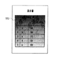
図5は、図4に示した帳票に対して本実施形態に係る地紋印刷を施して得られる帳票印刷結果を示す図である。 FIG. 5 is a diagram showing a form printing result obtained by applying the tint block printing according to the present embodiment to the form shown in FIG.
図5に示すように、フィールド401、402および403を含んだ矩形領域に見易さのための適度なマージン(マージンについては後述の図7で詳しく説明する)を加えて得られる領域501にのみ地紋画像が適用される。この領域501は、可変データの入力に応じた帳票の描画領域のサイズないし形状の可動に連動しており、この連動により、最終的に帳票画像に付与される地紋画像のサイズなしい形状を決定する。この可変データの入力に応じた領域サイズについては、後述の図14のS1403乃至S1406で詳しく述べることとする。
As shown in FIG. 5, only a
また、この地紋画像には濃度のグラデーションが施されている。このグラデーションは、図8以降で詳細に説明されるように、地紋画像を所定の方向に複数の連続する領域に分割し、それぞれの領域の地紋パラメータを徐々に変化させることによって実現される。図5に示す例は、地紋画像を図中上から下に向かう方向で水平な複数の領域に分割し、それぞれの領域の濃度が徐々に低くなるように地紋パラメータを変化させたものである。 The tint block image has a gradation of density. This gradation is realized by dividing the tint block image into a plurality of continuous regions in a predetermined direction and gradually changing the tint block parameter of each region, as will be described in detail in FIG. In the example shown in FIG. 5, the tint block image is divided into a plurality of horizontal regions in the direction from the top to the bottom in the figure, and the tint block parameter is changed so that the density of each region gradually decreases.
図6は、図5に示す帳票と地紋画像との合成を説明する図である。 FIG. 6 is a diagram for explaining synthesis of the form and the copy-forgery-inhibited pattern image shown in FIG.
図4に示したドキュメントテンプレート上に、「地紋コンテナ」を作成することによって帳票と地紋の合成を行う。ここで「コンテナ」とはデータ又はコンテンツを流し込む容器であり、枠のサイズが固定的な固定コンテナ、及び、枠のサイズが流し込まれるデータ又はコンテンツのサイズに応じて変更される可変コンテナの双方を含む。地紋コンテナは、地紋印刷する領域および地紋画像を特徴付ける各種パラメータを設定するためのドキュメントテンプレート上の図形である。図6は、帳票のコンテナ(フィールド(可変部分)のオブジェクトを指す)が作成されたドキュメントテンプレートに地紋コンテナを作成した状態を示している。本実施形態の地紋コンテナは、帳票のコンテナのサイズや形の変化に応じて、連動してそのサイズや形を変化させるものである。この連動は、具体的にはダイナミックリンク技術を用い地紋コンテナと可変の帳票のコンテナとを関連させることによって行う。このため、連動の詳細な説明は省略する。また、連動のための設定は以下で詳細が説明されるようにマージンの設定に伴って行われる。 A form and a background pattern are combined by creating a “background pattern container” on the document template shown in FIG. Here, the “container” is a container into which data or content is poured, and includes both a fixed container in which the frame size is fixed and a variable container in which the frame size is changed according to the size of data or content to be poured. Including. The copy-forgery-inhibited pattern container is a figure on the document template for setting various parameters characterizing the copy-forgery-inhibited pattern print area and the copy-forgery-inhibited pattern image. FIG. 6 shows a state in which a tint block container is created in a document template in which a form container (pointing to an object in a field (variable part)) is created. The copy-forgery-inhibited pattern container of the present embodiment changes its size and shape in conjunction with changes in the size and shape of the form container. More specifically, this linkage is performed by associating the tint block container with the variable form container using the dynamic link technique. For this reason, detailed description of the interlock is omitted. The setting for interlocking is performed in accordance with the margin setting as will be described in detail below.
図6において矩形領域501が地紋が付与される地紋コンテナの領域となる。すなわち、まず、図1に示したコンピュータシステムにおいて、「会社名」フィールド401、「金額」フィールド402、「明細」フィールド403を選択する。そして選択した状態で、「地紋コンテナ作成コマンド」を実行すると、選択している各フィールドの矩形を含む最小の矩形領域(つまり、マージン0の)に地紋コンテナが作成される。その後、図7に示すマージン属性設定のインターフェースを介して、上下左右それぞれのマージン603、601、602および604を設定する。このマージン設定によって、可変データに応じてそのサイズないし形状が変化する、帳票のコンテナの領域を特定するとともに、この帳票のコンテナに対する地紋コンテナの連動が可能となる。すなわち、ドキュメントテンプレート上で帳票の上下左右それぞれで最も外側にあるフィールドを基準としてマージンを設定する。図6に示す例では、明細フィールド403の最下辺が基準となってマージン601が設定される。これにより、地紋コンテナの下辺は帳票のコンテナの最下辺に関連付けられる。その結果、帳票が可変データの量が増して図中下方に拡大すると、それに連動して地紋画像も同じマージン601を持って拡大する。マージン602、603および604も同様に対応するフィールドの辺を基準としてそれらの設定がなされる。このように、帳票のサイズないし形状の変化に対応させて地紋画像のサイズないし形状を自動的に変化させることにより、帳票の地紋を適用したい領域に適切に地紋を適用することが可能となる。
In FIG. 6, a
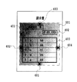
以上のように帳票のコンテナに連動してそのサイズなどが変化する地紋コンテナには、地紋属性が設定される。図8は、本実施形態の地紋属性の設定画面を示す図である。地紋属性は、図8に示すように、地紋画像を特徴付ける、潜像の文字列/書体/文字サイズ/文字角度、色、白抜きの有無、グラデーションの有無から構成される。さらに、グラデーション属性は、図9に示すグラデーション属性設定画面を介して、グラデーション地紋を特徴付ける、「解像度」、「方向」、「形状」、「開始濃度」、「終了濃度」の詳細設定がなされる。 As described above, the tint block attribute is set in the tint block container whose size changes in conjunction with the form container. FIG. 8 is a diagram showing a tint block attribute setting screen according to this embodiment. As shown in FIG. 8, the copy-forgery-inhibited pattern attribute is composed of a character string / font / character size / character angle, color, presence / absence of white, and presence / absence of gradation that characterize the copy-forgery-inhibited pattern image. Further, for the gradation attribute, detailed settings of “resolution”, “direction”, “shape”, “start density”, and “end density” characterizing the gradation copy-forgery-inhibited pattern are made via the gradation attribute setting screen shown in FIG. .
図10は、グラデーションの各属性を説明する図である。 FIG. 10 is a diagram for explaining each attribute of gradation.
図10において、「解像度」は、濃度変化の細かさであり、具体的には濃度が変化する領域のいくつの領域に分割するかを表している。本実施形態では、高(分割数64)/中(同32)/低(同16)の3種類の設定を可能としている。「形状」は、地紋コンテナ領域をグラデーション形状で分割するときの形を表わし、直線、図10に示す四角形、楕円などの設定が可能である。「方向」は、グラデーション開始位置とグラデーション終了位置によって定まり、グラデーション形状によって異なる。例えば、グラデーション形状が直線の場合は上→下、中央→上下、左上→右下などが可能であるが、楕円の場合は上→下、左上→右下、中央→外などが可能である。「開始濃度」および「終了濃度」は、標準濃度に対する割合を設定する。ここで、標準濃度とはグラデーション地紋印刷をしない場合に予め設定されている地紋印刷の濃度である。これら開始濃度と終了濃度の値により複写牽制範囲が定まることとなる。 In FIG. 10, “resolution” is the fineness of density change, and specifically represents how many of the areas where density changes are divided. In the present embodiment, three types of settings are possible: high (number of divisions 64) / medium (32) / low (16). “Shape” represents a shape when the tint block container area is divided into gradation shapes, and a straight line, a quadrangle, an ellipse, or the like shown in FIG. 10 can be set. The “direction” is determined by the gradation start position and the gradation end position, and varies depending on the gradation shape. For example, when the gradation shape is a straight line, the top → bottom, the center → top / bottom, the top left → bottom right, and the like are possible, but when the gradation shape is an ellipse, the top → bottom, the top left → bottom right, the center → out, etc. are possible. As the “starting concentration” and “ending concentration”, a ratio with respect to the standard concentration is set. Here, the standard density is a density of the tint block printing set in advance when the gradation tint pattern printing is not performed. The copy check range is determined by the values of the start density and the end density.
ここで、地紋濃度はグラデーションの開始位置から終了位置に向かい徐々に小さくなるが、地紋濃度が高いと印刷結果が見づらくなるし、地紋濃度が低いと複写後に潜像が消えてコンテンツの複写を部分的には牽制できなくなる。このため、開始濃度と終了濃度を適切な値に設定するだけでなく、重要なコンテンツの配置状況や地紋コンテナに関連付けられた可変領域が増減する方向、もしくは単純にデザインを考慮して、方向を設定することが望ましい。図11は、グラデーション地紋の方向を「上→下」にした場合を示す図である。また、図12は、「左上→右下」にした場合を示す図である。特に、図12に示すように、2列目の途中で行が終わるような表の場合、グラデーション地紋の方向を「左上→右下」に設定すると、コンテンツが何もない領域を複写牽制力が弱い領域にすることができる。結果として、複写を部分的には牽制できなくなるリスクを最小にしながらトナー消費量を抑えることができる。 Here, the tint block density gradually decreases from the gradation start position to the end position. However, if the tint block density is high, the print result becomes difficult to see, and if the tint block density is low, the latent image disappears after copying and the content is copied partially. It becomes impossible to check. For this reason, not only set the start density and end density to appropriate values, but also the direction in which important content is placed and the variable area associated with the tint block container increases or decreases, or simply the design is taken into account. It is desirable to set. FIG. 11 is a diagram illustrating a case where the direction of the gradation tint block is “up → down”. FIG. 12 is a diagram illustrating a case of “upper left → lower right”. In particular, as shown in FIG. 12, in the case of a table in which a row ends in the middle of the second column, if the gradation pattern is set to “upper left → lower right”, the copy restraining force is applied to an area where there is no content. Can be a weak area. As a result, it is possible to suppress toner consumption while minimizing the risk that copying cannot be partially controlled.
以上のようにして、帳票のコンテナに連動させて地紋コンテナが作成されたドキュメントテンプレートを、外部記憶装置15またはネットワーク17に接続しているデータベースにあらかじめ格納しておく。
As described above, the document template in which the tint block container is generated in conjunction with the form container is stored in advance in the database connected to the
図13は、以上説明した帳票のコンテナとこれに連動させた地紋コンテナの設定に基づく印刷データ生成処理を示すフローチャートである。 FIG. 13 is a flowchart showing print data generation processing based on the setting of the form container described above and the copy-forgery-inhibited pattern container linked to the form container.
先ず、ドキュメントテンプレートに1ページ分の帳票のコンテンツである帳票の可変データを流し込み(S1301)、帳票のレイアウトが決定される。この時、変更後の明細フィールド403の領域サイズを特定する。ここで可変データを流し込むとは、ドキュメントテンプレートの各フィールド(例えばフィールド401)の領域に入力データを配置する処理を意味する。各フィールドには、入力データをどのように配置するか設定されている。例えば、受け付ける入力データ型、文字型データの場合のフォントや段落属性、イメージ属性の場合のフィールド領域に対するフィッティングなどが設定されている。
First, variable data of a form, which is a form content for one page, is poured into the document template (S1301), and the form layout is determined. At this time, the area size of the
次に、作成したページの地紋コンテナのサイズを計算し(S1302)、そのサイズの地紋画像を生成する(S1303)。そして、生成した地紋画像を描画し(S1304)、その上に帳票の固定データおよび可変データを描画する(S1305)。処理されていない帳票の可変データがまだ残っているか否かを判断し(S1306)、残っている場合はステップS1301に戻り、それ以降のステップの処理を総ての帳票コンテンツが処理されるまで繰り返す。 Next, the size of the tint block container of the created page is calculated (S1302), and a tint block image of that size is generated (S1303). Then, the generated copy-forgery-inhibited pattern image is drawn (S1304), and the fixed data and variable data of the form are drawn thereon (S1305). It is determined whether or not the variable data of the unprocessed form still remains (S1306). If it remains, the process returns to step S1301, and the processing of the subsequent steps is repeated until all the form contents are processed. .
この図13のS1304及びS1305により、可変データの入力に応じた帳票の描画領域のサイズないし形状の可動に連動して、地紋画像の付与する第2領域を設定できる。また、該設定された領域に基づく地紋画像と、サイズないし形状が可動した領域における帳票の画像とに基づく、印刷を行う為のデータを生成できる。 In S1304 and S1305 in FIG. 13, the second area to which the copy-forgery-inhibited pattern image is added can be set in conjunction with the movement of the size or shape of the drawing area of the form according to the input of variable data. Also, data for printing can be generated based on the copy-forgery-inhibited pattern image based on the set area and the form image in the area where the size or shape is movable.
図14は、ステップS1302の地紋コンテナサイズ計算処理の詳細な処理を示すフローチャートである。先ず、求める領域を表わす変数R1を初期化し(S1401)、ループカウンタIを0に初期化する(S1402)。この変数R1は、実際は、例えば、地紋コンテナのサイズを横方向および縦方向それぞれの(上下、左右で)最も外側の座標で表したものである。次に、I番目の関連領域の外接矩形R2を求める(S1403)。この外接矩形R2も同様に、そのサイズを横方向および縦方向それぞれの最も外側の座標で表したものである。そして、R1とR2の和をR1とする(S1404)。この和もR1とR2のうち、横方向および縦方向それぞれで最も外側となる座標が和として表される。 FIG. 14 is a flowchart showing detailed processing of the tint block container size calculation processing in step S1302. First, a variable R1 representing a desired area is initialized (S1401), and a loop counter I is initialized to 0 (S1402). This variable R1 is actually, for example, the size of the tint block container expressed in outermost coordinates in the horizontal and vertical directions (up and down, left and right). Next, a circumscribed rectangle R2 of the I-th related area is obtained (S1403). Similarly, the circumscribed rectangle R2 represents the size by the outermost coordinates in the horizontal and vertical directions. The sum of R1 and R2 is set as R1 (S1404). This sum is also expressed as the sum of the outermost coordinates of R1 and R2 in the horizontal and vertical directions.
ここで、関連領域とは、地紋コンテナ作成時に帳票のコンテナにおいて関連付けられた図形やフィールドについて、ステップS1301でレイアウトした領域である。図6に示した例では、マージン603によって関連付けられたフィールド401の領域やマージン601、602、604によって関連付けられたフィールド403の領域である。
Here, the related area is an area that has been laid out in step S1301 with respect to the figures and fields associated in the form container when the tint block container is created. In the example illustrated in FIG. 6, the
ループカウンタIをカウントアップし(S1405)、Iが関連領域の数より小さいと判断したときは(S1406)、未だ処理していない関連領域が残っているとして、ステップS1403に戻り、それ以降の処理を繰り返し、総ての関連領域の外接矩形の和を求める。この結果、変数R1は、図6に示す例では、フィールド401の外接矩形とフィールド403の外接矩形の和となるから、横方向は、フィールド403の外接矩形の左右それぞれの最も外側の座標となり、縦方向は上側がフィールド401の外接矩形の上端の座標、下側がフィールド403の外接矩形の下端の座標となる。ステップS1406で総ての関連領域について処理を終了すると、地紋コンテナに設定されたマージン分だけ変数R1を拡大する。この拡大も、横方向および縦方向それぞれマージン分を足した座標が変数R1となる。そして、拡大の結果としてのR1がそのページの地紋コンテナのサイズとなる。図6に示す例では、領域501がこの変数R1が示す地紋画像の領域となる。
The loop counter I is counted up (S1405), and when it is determined that I is smaller than the number of related areas (S1406), it is determined that there are still related areas that have not been processed, and the process returns to step S1403. Is repeated to obtain the sum of the circumscribed rectangles of all the related regions. As a result, in the example shown in FIG. 6, the variable R1 is the sum of the circumscribed rectangle of the
図15は、図13に示したステップS1303の地紋画像生成の詳細な処理を示すフローチャートである。先ず、地紋コンテナに設定されている地紋属性に基づき、ステップS1302で求めた地紋コンテナサイズの潜像、すなわち、複写したときに現れる画像を生成する(S1501)。この処理は、従来の潜像画像生成処理と同様のため、その詳細な説明は省略する。この処理によって、図16に示すような潜像としての、例えば文字列が繰り返す画像が生成される。次に、地紋コンテナに設定された地紋属性においてグラデーションが設定されているか否かを判断する(S1502)。ここで、グラデーション地紋でないと判断したときは、潜像に対してグラデーションのない地紋処理を行った画像を生成し(S1503)、本処理を終了する。 FIG. 15 is a flowchart showing detailed processing of the tint block image generation in step S1303 shown in FIG. First, based on the copy-forgery-inhibited pattern attribute set in the copy-forgery-inhibited pattern container, a latent image of the copy-forgery-inhibited pattern container size obtained in step S1302, that is, an image that appears when copied is generated (S1501). Since this process is the same as the conventional latent image generation process, its detailed description is omitted. By this processing, an image as a latent image as shown in FIG. 16, for example, in which a character string is repeated is generated. Next, it is determined whether or not gradation is set in the background pattern attribute set in the background pattern container (S1502). If it is determined that the pattern is not a gradation pattern, an image obtained by performing a pattern process without gradation on the latent image is generated (S1503), and the process ends.
グラデーションが設定されているときは、地紋コンテナに設定された地紋属性の解像度に対応した分割数を求める(S1504)。本実施形態では、解像度には高/中/低の3種類の設定が可能であり、(高、中、低)=(64、32、16)の分割数が予め固定的に定められており、その中から選択して設定する。そのほかに、解像度に応じて固定的な間隔が定められていて、地紋コンテナのグラデーション方向の長さをその間隔で分割した数を分割数とすることなども可能である。次に、地紋領域のグラデーションの方向によって定まる開始位置から終了位置までを、同様に設定されているグラデーション形状に応じて、上記求めた分割数分に分割した領域を求める(S1505)。 When gradation is set, the number of divisions corresponding to the resolution of the background pattern attribute set in the background pattern container is obtained (S1504). In this embodiment, the resolution can be set to three types of high / medium / low, and the number of divisions (high, medium, low) = (64, 32, 16) is fixedly determined in advance. , Select from the settings. In addition, a fixed interval is determined according to the resolution, and the number obtained by dividing the gradation pattern length of the tint block container by the interval may be used as the division number. Next, an area obtained by dividing the start position to the end position determined by the gradation direction of the copy-forgery-inhibited pattern area into the determined number of divisions is obtained according to the similarly set gradation shape (S1505).
図17は、解像度:低、形状:長方形、方向:左上→右下のグラデーション属性の場合の地紋コンテナ領域の分割の例を示す図である。地紋コンテナ領域の左上点(開始位置)から右下点(終了位置)に至る対角線上を16分割し、開始位置から終了位置まで順にV0、V1、・・・、V16とする。そして、V0−Vn(n=1〜16)がそれぞれ対角線となる16個の長方形を順にR0、R1、・・・、R15とする。領域分割の方法はグラデーションの形状によって異なる。例えば、形状が楕円の場合は長方形の場合のR0〜R15に内接する4分の1楕円弧によって領域を分割する方法が考えられる。 FIG. 17 is a diagram showing an example of division of the tint block container area in the case of the gradation attribute of resolution: low, shape: rectangular, direction: upper left → lower right. The diagonal line from the upper left point (start position) to the lower right point (end position) of the tint block container area is divided into 16, and V0, V1,..., V16 are sequentially set from the start position to the end position. Then, 16 rectangles in which V0-Vn (n = 1 to 16) are diagonal lines are sequentially designated as R0, R1,..., R15. The area division method varies depending on the gradation shape. For example, when the shape is an ellipse, a method of dividing the region by a quarter elliptic arc inscribed in R0 to R15 in the case of a rectangle is conceivable.
地紋コンテナ領域を分割数で分割すると、次に、ループカウンタを0に初期化する(S1506)。そして、I番目のマスクMi(i=0〜分割数−1)を作成する(S1507)。このマスクMiは、長方形Ri(i=1〜分割数−1)から長方形R(i−1)を除いた領域である。ただし、0番目のマスクM0はR0である。図17に示す例では、マスクM1〜M15は、図18に示すようにそれぞれ逆L字型の領域になる。 Once the tint block container area is divided by the number of divisions, the loop counter is initialized to 0 (S1506). Then, an I-th mask Mi (i = 0 to the number of divisions-1) is created (S1507). This mask Mi is a region obtained by removing the rectangle R (i−1) from the rectangle Ri (i = 1 to the number of divisions−1). However, the 0th mask M0 is R0. In the example illustrated in FIG. 17, the masks M <b> 1 to M <b> 15 are inverted L-shaped regions as illustrated in FIG. 18.
マスクMiを作成すると、次に、図19に示すように潜像にMiのマスクをかけてマスク領域だけの潜像を生成する(S1508)。そして、I番目の地紋濃度を計算し(S1509)、その濃度でステップS1508で生成した画像に対して地紋処理を行う(S1510)。I番目の地紋濃度は、次の式で求められる。濃度(I)=開始濃度−(開始濃度−終了濃度)×I/分割数。また、地紋処理は、潜像を大ドット、それ以外を小ドットとし、求められた濃度で地紋画像を生成する処理である。この処理は、従来の地紋画像生成処理と同様のため、その詳細な説明は省略する。次に、それまでに生成した地紋画像と合成する(S1511)。各マスクMiが重なっていないので、この合成処理も重なる部分がない。そして、Iが分割数より小さい間は、未だ処理していない潜像について、ステップS1507以降の処理を繰り返し、総て領域の潜像について地紋処理を行う。この結果、地紋コンテナ領域のグラデーション地紋画像が生成される。 When the mask Mi is created, next, as shown in FIG. 19, the latent image of only the mask region is generated by applying the mask of Mi to the latent image (S 1508). Then, the I th background pattern density is calculated (S1509), and the background pattern processing is performed on the image generated in step S1508 with the density (S1510). The I th background pattern density is obtained by the following equation. Density (I) = starting density− (starting density−ending density) × I / number of divisions. The copy-forgery-inhibited pattern process is a process for generating a copy-forgery-inhibited pattern image with a determined density by setting a latent image as a large dot and other dots as small dots. Since this process is the same as the conventional tint block image generation process, its detailed description is omitted. Next, it is combined with the copy-forgery-inhibited pattern image generated so far (S1511). Since the respective masks Mi do not overlap, there is no overlapping portion in this combining process. As long as I is smaller than the number of divisions, the processes in and after step S1507 are repeated for the unprocessed latent images, and the background pattern processing is performed for all the latent images in the area. As a result, a gradation pattern image of the pattern pattern container area is generated.
このような段階的なグラデーションを地紋画像に施すことにより、複写条件、例えばコピー機の種類やコピー機の複写濃度などが異なっても、グラデーションの各段階の濃度のいくつかが上記複写条件に合致させることができる。これにより、複写した場合に潜像が明確に現れるようにすることができ、その複写物に複写牽制効果を持たせることができる。 By applying such stepwise gradation to the copy-forgery-inhibited pattern image, even if the copying conditions, such as the type of copying machine and the copying density of the copying machine, are different, some of the gradations at each gradation level match the above copying conditions. Can be made. As a result, the latent image can clearly appear when copied, and the copy can have a copy check effect.
以上のように作成された帳票に地紋が連動して合成された画像のデータは、プリンタ18(図1)で印刷可能な形態とされてそのプリンタ18に転送される。これにより、特に、帳票のサイズなどの変動に対応して適切に地紋が配された印刷結果を得ることができる。
Data of an image obtained by combining the copy-forgery-inhibited pattern with the form created as described above is transferred to the
(第2の実施の形態)
上記第1の実施の形態では、図7の設定画面を介してマージンを設定できるよう説明を行ってきた。しかし、マージンの設定は必ずしも必要でなく、マージンを固定としたり、又は、帳票のコンテナにおいて関連付けられた図形やフィールドについて、ステップS1301でレイアウトした領域と同じにしても良い。
(Second Embodiment)
In the first embodiment, the description has been given so that the margin can be set via the setting screen of FIG. However, it is not always necessary to set a margin. The margin may be fixed, or the figure and the field associated with the form container may be the same as the area laid out in step S1301.
(第3の実施の形態)
上記の実施形態では、可変データの入力によってそのサイズないし形状が変動可能な画像の例として帳票について説明したが、本発明の適用はこのような予め罫線などの枠がありその空白にデータを記入して形成される画像に限られないことはもちろんである。例えば、重要な議事録など、複写が望ましくない書類で1頁の用紙に記入されるデータの量が変わることがある書類にも本発明を適用した地紋印刷を行うことができる。
(Third embodiment)
In the above embodiment, a form has been described as an example of an image whose size or shape can be changed by input of variable data. However, the application of the present invention has a frame such as a ruled line in advance, and data is written in the blank. Of course, the image is not limited to the image formed. For example, it is possible to perform copy-forgery-inhibited pattern printing that applies the present invention to a document that is not desirable to be copied, such as an important minutes, and in which the amount of data written on one page of paper may change.
(他の実施形態)
上記の実施形態では、マージン設定によって地紋コンテナを帳票のコンテナに連動させるものとしたが、連動の方法はこれに限られない。例えば、地紋コンテナの辺に「リンク」を設定する方法でもよい。リンクは、マウスなどのポインティングデバイスを用いて地紋コンテナの1辺と帳票領域の1辺とを関連付けて、その水平もしくは垂直方向距離を設定する。リンクに設定された距離は、上記実施形態のマージンに相当する。また、リンクが設定されていない辺は用紙に対して固定的に位置する。
(Other embodiments)
In the above embodiment, the copy-forgery-inhibited pattern container is linked to the form container by the margin setting, but the linkage method is not limited to this. For example, a method of setting “link” on the side of the tint block container may be used. The link associates one side of the tint block container with one side of the form area using a pointing device such as a mouse, and sets the horizontal or vertical distance. The distance set for the link corresponds to the margin of the above embodiment. In addition, the side where the link is not set is fixedly positioned with respect to the sheet.
図20に示す例では、地紋コンテナの下辺が「明細」表フィールドの下辺から常に一定の垂直距離を保つようを設定している。これにより、「明細」表フィールドの行数が増えると、地紋コンテナの上左右辺は固定位置で下辺が下に延びる。リンクは地紋コンテナの複数の辺に対して設定可能であり、また、同じ辺に対して複数設定可能である。同じ辺に複数のリンクが設定されている場合は、その辺に対して各リンクのみが有効としたときの辺の位置のうち最も外側が地紋コンテナの領域となる。 In the example shown in FIG. 20, the lower side of the tint block container is set to always maintain a constant vertical distance from the lower side of the “detail” table field. Thus, when the number of rows in the “detail” table field increases, the upper left and right sides of the tint block container are fixed positions and the lower side extends downward. Links can be set for a plurality of sides of the tint block container, and a plurality of links can be set for the same side. When a plurality of links are set on the same side, the outermost position of the side position when only each link is valid for the side is the tint block container area.
(さらに他の実施形態)
上述した実施形態の機能を実現するように各種のデバイスを動作させるように該各種デバイスと接続された装置あるいはシステム内のコンピュータに、前記実施形態機能を実現するためのソフトウェアのプログラムコードを供給しても良い。つまり、そのシステムあるいは装置のコンピュータ(CPUあるいはMPU)を供給されたプログラムに従って前記各種デバイスを動作させることによって実施したものも本発明の範疇に含まれる。
(Still another embodiment)
A program code of software for realizing the functions of the embodiment is supplied to an apparatus or a computer in the system connected to the various devices so as to operate the various devices so as to realize the functions of the above-described embodiments. May be. That is, what was implemented by operating the said various devices according to the program supplied to the computer (CPU or MPU) of the system or apparatus is also contained in the category of the present invention.
またこの場合、図13〜図15に示したソフトウェアのプログラムコード自体が前述した実施形態の機能を実現することになる。従って、そのプログラムコード自体、およびそのプログラムコードをコンピュータに供給するための手段、例えばかかるプログラムコードを格納した記憶媒体は本発明を構成する。 In this case, the program code of the software shown in FIGS. 13 to 15 realizes the functions of the above-described embodiment. Accordingly, the program code itself and means for supplying the program code to the computer, for example, a storage medium storing the program code constitute the present invention.
かかるプログラムコードを格納する記憶媒体としては例えばフロッピー(登録商標)ディスク、ハードディスク、光ディスク、光磁気ディスク、CD−ROM、磁気テープ、不揮発性のメモリカード、ROM等を用いることができる。 As a storage medium for storing the program code, for example, a floppy (registered trademark) disk, a hard disk, an optical disk, a magneto-optical disk, a CD-ROM, a magnetic tape, a nonvolatile memory card, a ROM, or the like can be used.
また、コンピュータが供給されたプログラムコードを実行することにより、前述の実施形態の機能が実現されることには限定されない。そのプログラムコードがコンピュータにおいて稼働しているOS(オペレーティングシステム)、又は他のアプリ等と共同して前述の実施形態の機能が実現される場合にもかかるプログラムコードは本発明の実施形態に含まれることは言うまでもない。 In addition, the present invention is not limited to realizing the functions of the above-described embodiments by executing program code supplied by a computer. The program code is also included in the embodiment of the present invention even when the function of the above-described embodiment is realized in cooperation with an OS (operating system) running on the computer, another application, or the like. Needless to say.
さらに供給されたプログラムコードが、コンピュータの機能拡張ボードやコンピュータに接続された機能拡張ユニットに備わるメモリに格納された場合も想定される。つまり格納されたプログラムコードの指示に基づいてその機能拡張ボードや機能拡張ユニットに備わるCPU等が実際の処理の一部または全部を行い、その処理によって前述した実施形態の機能が実現される場合も本発明に含まれることは言うまでもない。 Further, it is assumed that the supplied program code is stored in a memory provided in a function expansion board of a computer or a function expansion unit connected to the computer. In other words, the CPU of the function expansion board or function expansion unit performs part or all of the actual processing based on the instruction of the stored program code, and the functions of the above-described embodiments may be realized by the processing. It goes without saying that it is included in the present invention.
11 入力装置
12 CPU
13 メモリ
14 表示装置
15 外部記憶装置
16 I/O,I/F
17 ネットワーク
18 プリンタ
401 会社名フィールド
402 金額フィールド
403 明細フィールド
501 地紋画像領域
601、602、603、604 マージン
11
13
17
Claims (17)
前記可変データの入力に応じた第1領域のサイズないし形状の可動に連動して、地紋画像を付与する第2領域を設定する領域設定手段と、
前記領域設定手段によって設定された前記第2領域に基づく地紋画像と、前記サイズないし形状が可動した第1領域における画像とに基づく印刷を行うためのデータを生成する生成手段と、
を具えたことを特徴とする画像処理装置。 An image processing apparatus for generating data for performing printing including a copy-forgery-inhibited pattern image in an image in a first area whose size or shape can be changed by input of variable data,
Area setting means for setting a second area to which a copy-forgery-inhibited pattern image is linked in conjunction with the movement of the size or shape of the first area according to the input of the variable data;
Generating means for generating data for performing printing based on the copy-forgery-inhibited pattern image based on the second area set by the area setting means and the image in the first area where the size or shape is movable;
An image processing apparatus comprising:
前記可変データの入力に応じた第1領域のサイズないし形状の可動に連動した領域に基づく地紋画像と、前記サイズないし形状が可動した第1領域における画像とに基づく、印刷を行うためのデータを生成する生成手段を具えたことを特徴とする画像処理装置。 An image processing apparatus for generating data for performing printing including a copy-forgery-inhibited pattern image in an image in a first area whose size or shape can be changed by input of variable data,
Data for performing printing based on a copy-forgery-inhibited pattern image based on an area linked to the movement of the size or shape of the first area according to the input of the variable data and an image in the first area where the size or shape is movable. An image processing apparatus comprising generation means for generating.
前記可変データの入力に応じた第1領域のサイズないし形状の可動に連動して、地紋画像を付与する第2領域を設定する領域設定工程と、
前記領域設定工程によって設定された前記第2領域に基づく地紋画像と、前記サイズないし形状が可動した第1領域における画像とに基づく印刷を行うためのデータを生成する生成工程と、
を有したことを特徴とする画像処理方法。 An image processing method for generating data for printing including a copy-forgery-inhibited pattern image in an image in a first region whose size or shape can be changed by input of variable data,
An area setting step for setting a second area to which a copy-forgery-inhibited pattern image is linked in conjunction with the movement of the size or shape of the first area according to the input of the variable data;
A generation step of generating data for performing printing based on the copy-forgery-inhibited pattern image based on the second region set by the region setting step and the image in the first region where the size or shape is movable;
An image processing method characterized by comprising:
前記可変データの入力に応じた第1領域のサイズないし形状の可動に連動した領域に基づく地紋画像と、前記サイズないし形状が可動した第1領域における画像とに基づく、印刷を行うためのデータを生成する生成工程を有したことを特徴とする画像処理方法。 An image processing method for generating data for performing printing including a copy-forgery-inhibited pattern image in an image in a first area whose size or shape can be changed by input of variable data,
Data for printing based on a copy-forgery-inhibited pattern image based on an area linked to the movement of the size or shape of the first area according to the input of the variable data and an image in the first area where the size or shape is movable. An image processing method comprising a generation step of generating.
A program causing a computer to function as the image processing apparatus according to any one of claims 1 to 8.
Priority Applications (2)
| Application Number | Priority Date | Filing Date | Title |
|---|---|---|---|
| JP2005274430A JP2007088764A (en) | 2005-09-21 | 2005-09-21 | Image processing apparatus and method therefor |
| US11/531,767 US20070065205A1 (en) | 2005-09-21 | 2006-09-14 | Image forming apparatus, and method of image processing |
Applications Claiming Priority (1)
| Application Number | Priority Date | Filing Date | Title |
|---|---|---|---|
| JP2005274430A JP2007088764A (en) | 2005-09-21 | 2005-09-21 | Image processing apparatus and method therefor |
Publications (2)
| Publication Number | Publication Date |
|---|---|
| JP2007088764A true JP2007088764A (en) | 2007-04-05 |
| JP2007088764A5 JP2007088764A5 (en) | 2008-11-06 |
Family
ID=37884292
Family Applications (1)
| Application Number | Title | Priority Date | Filing Date |
|---|---|---|---|
| JP2005274430A Withdrawn JP2007088764A (en) | 2005-09-21 | 2005-09-21 | Image processing apparatus and method therefor |
Country Status (2)
| Country | Link |
|---|---|
| US (1) | US20070065205A1 (en) |
| JP (1) | JP2007088764A (en) |
Families Citing this family (2)
| Publication number | Priority date | Publication date | Assignee | Title |
|---|---|---|---|---|
| KR101340562B1 (en) * | 2007-04-10 | 2013-12-11 | 삼성전자주식회사 | Apparatus of copying and user interface method thereof |
| JP2010087780A (en) * | 2008-09-30 | 2010-04-15 | Fuji Xerox Co Ltd | Image forming apparatus |
Family Cites Families (3)
| Publication number | Priority date | Publication date | Assignee | Title |
|---|---|---|---|---|
| US5197765A (en) * | 1991-07-12 | 1993-03-30 | The Standard Register Company | Varying tone securing document |
| US7196822B2 (en) * | 2001-08-14 | 2007-03-27 | Amgraf, Inc. | Security document manufacturing method and apparatus using halftone dots that contain microscopic images |
| JP3941525B2 (en) * | 2002-01-30 | 2007-07-04 | カシオ計算機株式会社 | Print control apparatus and program |
-
2005
- 2005-09-21 JP JP2005274430A patent/JP2007088764A/en not_active Withdrawn
-
2006
- 2006-09-14 US US11/531,767 patent/US20070065205A1/en not_active Abandoned
Also Published As
| Publication number | Publication date |
|---|---|
| US20070065205A1 (en) | 2007-03-22 |
Similar Documents
| Publication | Publication Date | Title |
|---|---|---|
| US7149451B2 (en) | Image processing apparatus and image processing method | |
| JP3673643B2 (en) | Print layout apparatus, print layout method, and storage medium | |
| JP5074751B2 (en) | EDITING DEVICE, EDITING DEVICE CONTROL METHOD, AND PROGRAM | |
| US7742196B2 (en) | Information processing apparatus and method for processing information | |
| JP3969801B2 (en) | Information processing apparatus and method, and program storage medium | |
| JP3941525B2 (en) | Print control apparatus and program | |
| JP2005117589A (en) | Information processing apparatus and information processing method | |
| JP2007143111A (en) | Information processing apparatus and control method therefor | |
| JP2007115078A (en) | Information processor, printing device, information processing method, program and storage medium | |
| JPS59137987A (en) | Graphic pattern overlapping method | |
| JP4534823B2 (en) | Print data editing apparatus and print data editing program | |
| TW200807263A (en) | Document editing systems and methods | |
| JP2007088764A (en) | Image processing apparatus and method therefor | |
| JP3527615B2 (en) | Layout typesetting method | |
| JP2018103406A (en) | Solid image formation system, program and solid structure | |
| JP2006260387A (en) | Printing data editing device, and printing data editing program | |
| JP4003456B2 (en) | Print control apparatus and program | |
| US20070201098A1 (en) | Bleed creation for documents | |
| JP2021063949A (en) | Information processing apparatus and image forming apparatus | |
| JP2007174387A (en) | Information processing apparatus and control method thereof | |
| JP4305343B2 (en) | Image processing device | |
| JP2007110325A (en) | Information processing apparatus and information processing method | |
| JP2009111853A (en) | Image processing apparatus and program | |
| JP2004104161A (en) | Image processing method, image processing apparatus, storage medium, and program | |
| JP2007122486A (en) | Web document processing method, program, and storage medium |
Legal Events
| Date | Code | Title | Description |
|---|---|---|---|
| A521 | Request for written amendment filed |
Free format text: JAPANESE INTERMEDIATE CODE: A523 Effective date: 20080922 |
|
| A621 | Written request for application examination |
Free format text: JAPANESE INTERMEDIATE CODE: A621 Effective date: 20080922 |
|
| A761 | Written withdrawal of application |
Free format text: JAPANESE INTERMEDIATE CODE: A761 Effective date: 20100205 |