JP2007073587A - Exposure method, aligner, and method of manufacturing device - Google Patents
Exposure method, aligner, and method of manufacturing device Download PDFInfo
- Publication number
- JP2007073587A JP2007073587A JP2005256129A JP2005256129A JP2007073587A JP 2007073587 A JP2007073587 A JP 2007073587A JP 2005256129 A JP2005256129 A JP 2005256129A JP 2005256129 A JP2005256129 A JP 2005256129A JP 2007073587 A JP2007073587 A JP 2007073587A
- Authority
- JP
- Japan
- Prior art keywords
- liquid
- film
- exposure
- substrate
- refractive index
- Prior art date
- Legal status (The legal status is an assumption and is not a legal conclusion. Google has not performed a legal analysis and makes no representation as to the accuracy of the status listed.)
- Pending
Links
Images


Landscapes
- Exposure And Positioning Against Photoresist Photosensitive Materials (AREA)
- Exposure Of Semiconductors, Excluding Electron Or Ion Beam Exposure (AREA)
Abstract
Description
本発明は、基板を露光する露光方法及び露光装置、並びにデバイス製造方法に関するものである。 The present invention relates to an exposure method and an exposure apparatus for exposing a substrate, and a device manufacturing method.
フォトリソグラフィ工程で用いられる露光装置において、下記特許文献に開示されているような、基板上に液体の液浸領域を形成し、その液体を介して基板を露光する液浸露光装置が案出されている。
液浸法に基づいて基板を露光する場合、液浸領域の液体が基板に影響を及ぼす可能性がある。例えば液体が基板上に形成されている膜に影響を及ぼした場合、基板に形成されるパターンに欠陥が生じる等、露光不良が発生する不具合が生じる可能性がある。 When the substrate is exposed based on the immersion method, the liquid in the immersion region may affect the substrate. For example, when the liquid affects the film formed on the substrate, there is a possibility that a defective exposure occurs such as a defect in a pattern formed on the substrate.
本発明はこのような事情に鑑みてなされたものであって、露光不良の発生を抑え、基板を良好に露光することができる露光方法及び露光装置、並びにその露光方法及び露光装置を用いるデバイス製造方法を提供することを目的とする。 The present invention has been made in view of such circumstances, and an exposure method and an exposure apparatus that can satisfactorily expose a substrate while suppressing the occurrence of exposure failure, and a device manufacturing using the exposure method and the exposure apparatus It aims to provide a method.
上記の課題を解決するため、本発明は実施の形態に示す各図に対応付けした以下の構成を採用している。但し、各要素に付した括弧付き符号はその要素の例示に過ぎず、各要素を限定するものではない。 In order to solve the above-described problems, the present invention employs the following configurations corresponding to the respective drawings shown in the embodiments. However, the reference numerals with parentheses attached to each element are merely examples of the element and do not limit each element.
本発明の第1の態様に従えば、基板(P)上に露光光(EL)を照射して基板(P)を露光する露光方法において、基板(P)の基材(W)上に所定の膜(Tc)を被覆する被覆工程と、膜(Tc)上に液体(LQ)の液浸領域(LR)を形成して露光光(EL)を照射する露光工程とを有し、膜(Tc)の露光光(EL)に対する屈折率と液体(LQ)の露光光(EL)に対する屈折率とをほぼ同じにする露光方法が提供される。 According to the first aspect of the present invention, in the exposure method of exposing the substrate (P) by irradiating the substrate (P) with exposure light (EL), the substrate (P) has a predetermined surface on the substrate (W). A coating process for coating the film (Tc), and an exposure process for forming an immersion region (LR) of the liquid (LQ) on the film (Tc) and irradiating exposure light (EL). An exposure method is provided in which the refractive index of Tc) for exposure light (EL) and the refractive index of liquid (LQ) for exposure light (EL) are substantially the same.
本発明の第1の態様によれば、液浸領域の液体を介して基板を露光する際、露光不良の発生を抑え、基板を良好に露光することができる。 According to the first aspect of the present invention, when the substrate is exposed through the liquid in the liquid immersion region, it is possible to suppress the occurrence of defective exposure and to expose the substrate satisfactorily.
本発明の第2の態様に従えば、上記態様の露光方法を用いるデバイス製造方法が提供される。 According to the second aspect of the present invention, there is provided a device manufacturing method using the exposure method of the above aspect.
本発明の第2の態様によれば、露光不良の発生が抑えられた露光方法を用いてデバイスを製造することができる。 According to the 2nd aspect of this invention, a device can be manufactured using the exposure method by which generation | occurrence | production of the exposure defect was suppressed.
本発明の第3の態様に従えば、基板(P)上に露光光(EL)を照射して基板(P)を露光する露光装置において、基板(P)の基材(W)上には所定の膜(Tc)が被覆されており、膜(Tc)上に液浸領域(LR)を形成するための液体(LQ)を供給する液体供給装置(12など)を備え、液体供給装置(12など)は、膜(Tc)の露光光(EL)に対する屈折率とほぼ同じ屈折率を有する液体(LQ)を供給する露光装置(EX)が提供される。 According to the third aspect of the present invention, in the exposure apparatus that exposes the substrate (P) by irradiating the substrate (P) with exposure light (EL), the substrate (P) has a substrate (W) A predetermined film (Tc) is covered, and a liquid supply device (12 or the like) that supplies a liquid (LQ) for forming a liquid immersion region (LR) on the film (Tc) is provided. 12) is provided with an exposure apparatus (EX) that supplies a liquid (LQ) having substantially the same refractive index as that of the exposure light (EL) of the film (Tc).
本発明の第3の態様によれば、液浸領域の液体を介して基板を露光する際、露光不良の発生を抑え、基板を良好に露光することができる。 According to the third aspect of the present invention, when the substrate is exposed through the liquid in the liquid immersion region, it is possible to suppress the occurrence of defective exposure and to expose the substrate satisfactorily.
本発明の第4の態様に従えば、上記態様の露光装置(EX)を用いるデバイス製造方法が提供される。 According to the fourth aspect of the present invention, there is provided a device manufacturing method using the exposure apparatus (EX) of the above aspect.
本発明の第4の態様によれば、露光不良の発生が抑えられた露光装置を用いてデバイスを製造することができる。 According to the fourth aspect of the present invention, a device can be manufactured using an exposure apparatus in which the occurrence of exposure failure is suppressed.
本発明によれば、露光不良の発生を抑え、基板を良好に露光することができ、所望の性能を有するデバイスを製造することができる。 According to the present invention, it is possible to suppress the occurrence of exposure failure, to expose the substrate satisfactorily, and to manufacture a device having desired performance.
以下、本発明の実施形態について図面を参照しながら説明するが、本発明はこれに限定されない。なお、以下の説明においては、XYZ直交座標系を設定し、このXYZ直交座標系を参照しつつ各部材の位置関係について説明する。そして、水平面内における所定方向をX軸方向、水平面内においてX軸方向と直交する方向をY軸方向、X軸方向及びY軸方向のそれぞれに直交する方向(すなわち鉛直方向)をZ軸方向とする。また、X軸、Y軸、及びZ軸まわりの回転(傾斜)方向をそれぞれ、θX、θY、及びθZ方向とする。 Hereinafter, embodiments of the present invention will be described with reference to the drawings, but the present invention is not limited thereto. In the following description, an XYZ orthogonal coordinate system is set, and the positional relationship of each member will be described with reference to this XYZ orthogonal coordinate system. The predetermined direction in the horizontal plane is the X-axis direction, the direction orthogonal to the X-axis direction in the horizontal plane is the Y-axis direction, and the direction orthogonal to each of the X-axis direction and the Y-axis direction (that is, the vertical direction) is the Z-axis direction. To do. Further, the rotation (inclination) directions around the X axis, Y axis, and Z axis are the θX, θY, and θZ directions, respectively.
<第1実施形態>
第1実施形態について説明する。図1は第1実施形態に係る露光装置EXを備えたデバイス製造システムSYSを示す図である。図1において、デバイス製造システムSYSは、露光装置EXと、露光装置EXに接続されたコータ・デベロッパ装置CDとを備えている。
<First Embodiment>
A first embodiment will be described. FIG. 1 is a view showing a device manufacturing system SYS including an exposure apparatus EX according to the first embodiment. In FIG. 1, the device manufacturing system SYS includes an exposure apparatus EX and a coater / developer apparatus CD connected to the exposure apparatus EX.
露光装置EXは、マスクMを保持して移動可能なマスクステージ3と、基板Pを保持する基板ホルダ4Hを有し、基板ホルダ4Hに基板Pを保持して移動可能な基板ステージ4と、マスクステージ3に保持されているマスクMを露光光ELで照明する照明光学系ILと、露光光ELで照明されたマスクMのパターン像を基板P上に投影する投影光学系PLと、露光装置EX全体の動作を制御する制御装置7とを備えている。
The exposure apparatus EX includes a
本実施形態の露光装置EXは、露光波長を実質的に短くして解像度を向上するとともに焦点深度を実質的に広くするために液浸法を適用した液浸露光装置であって、基板ステージ4に保持された基板P上に液体LQの液浸領域LRを形成し、液浸領域LRの液体LQを介して基板P上に露光光ELを照射して基板Pを露光する。本実施形態では、液体LQとして、水(純水)を用いる。 The exposure apparatus EX of the present embodiment is an immersion exposure apparatus to which an immersion method is applied in order to improve the resolution by substantially shortening the exposure wavelength and substantially increase the depth of focus. An immersion region LR of the liquid LQ is formed on the substrate P held by the substrate P, and the substrate P is exposed by irradiating the exposure light EL onto the substrate P through the liquid LQ of the immersion region LR. In the present embodiment, water (pure water) is used as the liquid LQ.
コータ・デベロッパ装置CDは、露光処理される前の基板Pの基材上に所定の膜を被覆するコーティング装置、及び露光処理された後の基板Pを現像するデベロッパ装置を含む。露光装置EXとコータ・デベロッパ装置CDとはインターフェースIFを介して接続されており、基板Pは不図示の搬送装置により、露光装置EXとコータ・デベロッパ装置CDとの間でインターフェースIFを介して搬送可能である。 The coater / developer apparatus CD includes a coating apparatus that coats a predetermined film on the base material of the substrate P before the exposure process, and a developer apparatus that develops the substrate P after the exposure process. The exposure apparatus EX and the coater / developer apparatus CD are connected via an interface IF, and the substrate P is transferred between the exposure apparatus EX and the coater / developer apparatus CD via an interface IF by a transfer apparatus (not shown). Is possible.
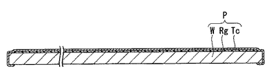
図2はコータ・デベロッパ装置CDのコーティング装置によって所定の膜が被覆された基材を含む基板Pの一例を示す図である。図2において、基板Pは、半導体ウエハ等の基材Wと、その基材W上に被覆された第1膜Rgと、その第1膜Rg上に被覆された第2膜Tcとを有している。第1膜Rgは、感光材(フォトレジスト)からなる膜である。第2膜Tcは、トップコート膜と呼ばれる膜であって、例えば液体LQから第1膜Rgや基材Wを保護する機能などを有しており、液体LQに対して撥液性(撥水性)を有している。また、撥液性の膜である第2膜Tcを設けることにより、液体LQの回収性を高めることもできる。第1膜Rgは、例えばスピンコーティング方式によって、基材W上に感光材(フォトレジスト)を塗布することによって形成される。同様に、第2膜Tcも、トップコート膜を形成するための材料を塗布することによって形成される。液体LQの液浸領域LRは、基板Pの第2膜Tc上に形成されるため、基板Pのうち、第2膜Tcが、液浸領域LRの液体LQと接触する液体接触面を形成する。 FIG. 2 is a view showing an example of a substrate P including a base material on which a predetermined film is coated by a coating apparatus of the coater / developer apparatus CD. In FIG. 2, the substrate P has a base material W such as a semiconductor wafer, a first film Rg coated on the base material W, and a second film Tc coated on the first film Rg. ing. The first film Rg is a film made of a photosensitive material (photoresist). The second film Tc is a film called a top coat film, and has a function of protecting the first film Rg and the substrate W from the liquid LQ, for example, and is liquid repellent (water repellent) with respect to the liquid LQ. )have. Further, by providing the second film Tc which is a liquid repellent film, the recoverability of the liquid LQ can be improved. The first film Rg is formed by applying a photosensitive material (photoresist) on the substrate W by, for example, a spin coating method. Similarly, the second film Tc is also formed by applying a material for forming the topcoat film. Since the liquid immersion region LR of the liquid LQ is formed on the second film Tc of the substrate P, the second film Tc of the substrate P forms a liquid contact surface that contacts the liquid LQ of the liquid immersion region LR. .
次に、図3を参照しながら露光装置EXについて説明する。図3は本実施形態に係る露光装置EXを示す概略構成図である。露光装置EXは、投影光学系PLの像面近傍の露光光ELの光路Kを液体LQで満たして液浸領域LRを形成する液浸システム1を備えている。液浸システム1の動作は制御装置7に制御される。液浸システム1は、投影光学系PLの複数の光学素子のうち、投影光学系PLの像面に最も近い最終光学素子FLの下面と、投影光学系PLの像面側に配置された基板ホルダ4H上の基板Pの表面との間の露光光ELの光路Kを液体LQで満たすように基板P上に液浸領域LRを形成する。 Next, the exposure apparatus EX will be described with reference to FIG. FIG. 3 is a schematic block diagram that shows the exposure apparatus EX according to the present embodiment. The exposure apparatus EX includes an immersion system 1 that fills the optical path K of the exposure light EL in the vicinity of the image plane of the projection optical system PL with the liquid LQ to form an immersion area LR. The operation of the immersion system 1 is controlled by the control device 7. The immersion system 1 includes a substrate holder disposed on the lower surface of the final optical element FL closest to the image plane of the projection optical system PL and the image plane side of the projection optical system PL among the plurality of optical elements of the projection optical system PL. A liquid immersion region LR is formed on the substrate P so that the optical path K of the exposure light EL between the surface of the substrate P on 4H is filled with the liquid LQ.
露光装置EXは、少なくともマスクMのパターン像を基板Pに投影している間、液浸システム1を用いて、露光光ELの光路Kを液体LQで満たす。露光装置EXは、投影光学系PLと露光光ELの光路Kに満たされた液体LQとを介してマスクMを通過した露光光ELを基板ホルダ4Hに保持された基板P上に照射することによって、マスクMのパターン像を基板P上に投影して、基板Pを露光する。また、本実施形態の露光装置EXは、最終光学素子FLと基板Pとの間の露光光ELの光路Kに満たされた液体LQが、投影光学系PLの投影領域ARを含む基板P上の一部の領域に、投影領域ARよりも大きく且つ基板Pよりも小さい液体LQの液浸領域LRを局所的に形成する局所液浸方式を採用している。
The exposure apparatus EX fills the optical path K of the exposure light EL with the liquid LQ using the liquid immersion system 1 at least while the pattern image of the mask M is projected onto the substrate P. The exposure apparatus EX irradiates the exposure light EL that has passed through the mask M onto the substrate P held by the
なお、液浸領域LRは、基板P上だけでなく、投影光学系PLの像面側において、最終光学素子FLの下面と対向する位置に配置された物体上、例えば基板ステージ4の一部などにも形成可能である。
The liquid immersion region LR is not only on the substrate P but also on an object disposed at a position facing the lower surface of the final optical element FL on the image plane side of the projection optical system PL, for example, a part of the
照明光学系ILは、マスクM上の所定の照明領域を均一な照度分布の露光光ELで照明するものである。照明光学系ILから射出される露光光ELとしては、例えば水銀ランプから射出される輝線(g線、h線、i線)及びKrFエキシマレーザ光(波長248nm)等の遠紫外光(DUV光)や、ArFエキシマレーザ光(波長193nm)及びF2レーザ光(波長157nm)等の真空紫外光(VUV光)などが用いられる。本実施形態においてはArFエキシマレーザ光が用いられる。 The illumination optical system IL illuminates a predetermined illumination area on the mask M with exposure light EL having a uniform illuminance distribution. The exposure light EL emitted from the illumination optical system IL is, for example, far ultraviolet light (DUV light) such as emission lines (g line, h line, i line) and KrF excimer laser light (wavelength 248 nm) emitted from a mercury lamp. Alternatively, vacuum ultraviolet light (VUV light) such as ArF excimer laser light (wavelength 193 nm) and F 2 laser light (wavelength 157 nm) is used. In this embodiment, ArF excimer laser light is used.
マスクステージ3は、リニアモータ等のアクチュエータを含むマスクステージ駆動装置3Dの駆動により、マスクMを保持した状態で、X軸、Y軸、及びθZ方向に移動可能である。マスクステージ3(ひいてはマスクM)の位置情報は、レーザ干渉計3Lによって計測される。レーザ干渉計3Lは、マスクステージ3上に設けられた移動鏡3Kを用いてマスクステージ3の位置情報を計測する。制御装置7は、レーザ干渉計3Lの計測結果に基づいてマスクステージ駆動装置3Dを駆動し、マスクステージ3に保持されているマスクMの位置制御を行う。なお、ここでいうマスクは基板上に縮小投影されるデバイスパターンを形成されたレチクルを含む。また、本実施形態においては、マスクとして透過型のマスクを用いるが、反射型のマスクを用いてもよい。
The
投影光学系PLは、マスクMのパターン像を所定の投影倍率で基板Pに投影するものであって、複数の光学素子を有しており、それら光学素子は鏡筒PKで保持されている。本実施形態の投影光学系PLは、その投影倍率が例えば1/4、1/5、1/8等の縮小系である。なお、投影光学系PLは等倍系及び拡大系のいずれでもよい。本実施形態では、投影光学系PLの光軸AXはZ軸方向と平行となっている。また、投影光学系PLは、反射光学素子を含まない屈折系、屈折光学素子を含まない反射系、反射光学素子と屈折光学素子とを含む反射屈折系のいずれであってもよい。また、投影光学系PLは、倒立像と正立像とのいずれを形成してもよい。 The projection optical system PL projects the pattern image of the mask M onto the substrate P at a predetermined projection magnification, and has a plurality of optical elements, and these optical elements are held by a lens barrel PK. The projection optical system PL of the present embodiment is a reduction system whose projection magnification is, for example, 1/4, 1/5, 1/8 or the like. Note that the projection optical system PL may be either an equal magnification system or an enlargement system. In the present embodiment, the optical axis AX of the projection optical system PL is parallel to the Z-axis direction. The projection optical system PL may be any of a refractive system that does not include a reflective optical element, a reflective system that does not include a refractive optical element, and a catadioptric system that includes a reflective optical element and a refractive optical element. Further, the projection optical system PL may form either an inverted image or an erect image.
基板ステージ4は、基板Pを保持する基板ホルダ4Hを有しており、リニアモータ等のアクチュエータを含む基板ステージ駆動装置4Dの駆動により、基板ホルダ4Hに基板Pを保持した状態で、ベース部材BP上で、X軸、Y軸、Z軸、θX、θY、及びθZ方向の6自由度の方向に移動可能である。基板ホルダ4Hは、基板ステージ4上に設けられた凹部4Rに配置されており、基板ステージ4のうち凹部4R以外の上面4Fは、基板ホルダ4Hに保持された基板Pの表面とほぼ同じ高さ(面一)になるような平坦面となっている。なお、基板ホルダ4Hに保持された基板Pの表面と、基板ステージ4の上面4Fとの間に段差があってもよい。
The
基板ステージ4(ひいては基板P)の位置情報は、レーザ干渉計4Lによって計測される。レーザ干渉計4Lは、基板ステージ4に設けられた移動鏡4Kを用いて、基板ステージ4のX軸、Y軸、及びθZ方向に関する位置情報を計測する。また、基板ステージ4に保持されている基板Pの表面の面位置情報(Z軸、θX、及びθY方向に関する位置情報)は、不図示のフォーカス・レベリング検出系によって検出される。制御装置7は、レーザ干渉計4Lの計測結果及びフォーカス・レベリング検出系の検出結果に基づいて、基板ステージ駆動装置4Dを駆動し、基板ステージ4に保持されている基板Pの位置制御を行う。
The position information of the substrate stage 4 (and thus the substrate P) is measured by the
次に、液浸システム1について図4を参照しながら説明する。図4は図3の要部を示す拡大図である。液浸システム1は、投影光学系PLの最終光学素子FLと、その最終光学素子FLと対向する位置に配置され、基板ホルダ4Hに保持された基板Pとの間の露光光ELの光路Kを液体LQで満たす。液浸システム1は、最終光学素子FLと基板Pとの間の露光光ELの光路Kの近傍に設けられ、その光路Kに対して液体LQを供給するための供給口12及び液体LQを回収するための回収口22を有するノズル部材71と、供給管13、及びノズル部材71の内部に形成された供給流路14を介して供給口12に液体LQを供給する液体供給装置11と、ノズル部材71の回収口22から回収された液体LQを、ノズル部材71の内部に形成された回収流路24、及び回収管23を介して回収する液体回収装置21とを備えている。供給口12と供給管13とは供給流路14を介して接続されており、回収口22と回収管23とは回収流路24を介して接続されている。本実施形態においては、ノズル部材71は、露光光ELの光路Kを囲むように環状に設けられており、液体LQを供給する供給口12は、ノズル部材71のうち、露光光ELの光路Kを向く内側面に設けられ、液体LQを回収する回収口22は、ノズル部材71のうち、基板Pの表面と対向する下面に設けられている。また、本実施形態においては、回収口22には多孔部材(メッシュ)25が配置されている。
Next, the liquid immersion system 1 will be described with reference to FIG. FIG. 4 is an enlarged view showing a main part of FIG. The immersion system 1 is disposed on the optical path K of the exposure light EL between the final optical element FL of the projection optical system PL and the substrate P that is disposed at a position facing the final optical element FL and held by the
液体供給装置11は、供給する液体LQの温度を調整する温度調整装置、液体LQ中の気体成分を低減する脱気装置、及び液体LQ中の異物を取り除くフィルタユニット等を備えており、清浄で温度調整された液体LQを送出可能である。また、液体回収装置21は、真空系等を備えており、液体LQを回収可能である。液体供給装置11及び液体回収装置21の動作は制御装置7に制御される。液体供給装置11から送出された液体LQは、供給管13、及びノズル部材71の供給流路14を流れた後、供給口12より露光光ELの光路Kに供給される。また、液体回収装置21を駆動することにより回収口22から回収された液体LQは、ノズル部材71の回収流路24を流れた後、回収管23を介して液体回収装置21に回収される。制御装置7は、液浸システム1を制御して、液体供給装置11による液体供給動作と液体回収装置21による液体回収動作とを並行して行うことで、最終光学素子FLと基板Pとの間の露光光ELの光路Kを液体LQで満たし、基板P上の一部の領域に液体LQの液浸領域LRを局所的に形成する。
The
図4に示すように、液体LQの液浸領域LRは、基板Pの第2膜Tc上に形成され、基板Pのうち、第2膜Tcが、液浸領域LRの液体LQと接触する。第2膜Tcに接触した液体LQが第2膜Tcの内部に浸入する可能性があり、第2膜Tcに影響を及ぼす可能性がある。 As illustrated in FIG. 4, the liquid immersion region LR of the liquid LQ is formed on the second film Tc of the substrate P, and the second film Tc of the substrate P is in contact with the liquid LQ of the liquid immersion region LR. The liquid LQ in contact with the second film Tc may enter the inside of the second film Tc and may affect the second film Tc.
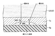
例えば、図5の模式図に示すように、液体LQが第2膜Tcの内部に浸入する(染み込む)可能性がある。図5に示す例では、第2膜Tcの内部に浸入した液体LQは、第1膜Rgと第2膜Tcとの間に存在している。このような状態で、基板Pに露光光ELが照射された場合、浸入した液体LQによって、第1膜Rg(又は基材W)に対する露光光ELの照射状態が変動する可能性がある。すなわち、第2膜Tcの内部に浸入した液体部分で、露光光ELの光路が変化する可能性がある。第2膜Tcの露光光ELに対する屈折率と、液体LQの露光光ELに対する屈折率とが大きく異なっている場合、第2膜Tcの内部に浸入した液体部分、具体的には、第2膜Tcの内部に浸入した液体LQと第2膜Tcとの界面において、露光光ELが大きく屈折し、露光光ELの照射状態が大きく変動する可能性がある。第2膜Tcの内部に浸入した液体部分で露光光ELの光路が変化した場合、第1膜Rgの所望位置に露光光ELが到達せず、所望のパターン像が形成できず、基材Wに形成されるパターンに欠陥が生じる等、露光不良が発生する不具合が生じる可能性がある。また、第2膜Tcの内部に浸入した液体LQと第2膜Tcとの界面において、露光光ELの一部が反射し、所望の光量(強度)を有する露光光ELで第1膜Rgを照射できなくなる不具合が生じる可能性もある。また、浸入した液体部分によって、露光光ELが乱反射する可能性もある。 For example, as shown in the schematic diagram of FIG. 5, there is a possibility that the liquid LQ may enter (permeate) the second film Tc. In the example shown in FIG. 5, the liquid LQ that has entered the second film Tc exists between the first film Rg and the second film Tc. In such a state, when the exposure light EL is irradiated onto the substrate P, the irradiation state of the exposure light EL on the first film Rg (or the substrate W) may vary depending on the liquid LQ that has entered. That is, there is a possibility that the optical path of the exposure light EL changes in the liquid portion that has entered the second film Tc. When the refractive index of the second film Tc with respect to the exposure light EL is greatly different from the refractive index of the liquid LQ with respect to the exposure light EL, the liquid portion that has entered the second film Tc, specifically, the second film There is a possibility that the exposure light EL is largely refracted at the interface between the liquid LQ that has entered the inside of the Tc and the second film Tc, and the irradiation state of the exposure light EL varies greatly. When the optical path of the exposure light EL changes in the liquid portion that has entered the second film Tc, the exposure light EL does not reach the desired position of the first film Rg, and a desired pattern image cannot be formed. There is a possibility that a defect in which an exposure failure occurs, such as a defect in a pattern formed on the substrate, occurs. Further, a part of the exposure light EL is reflected at the interface between the liquid LQ that has entered the second film Tc and the second film Tc, and the first film Rg is applied with the exposure light EL having a desired light amount (intensity). There is a possibility that a problem that the irradiation cannot be performed may occur. Further, the exposure light EL may be irregularly reflected by the liquid portion that has entered.
また、図6に示すように、第2膜Tcの内部に浸入した液体LQによって、第2膜Tcが膨潤するなどして、第2膜Tcの形状が局所的に変化する可能性もある。図6においても、その第2膜Tcの内部に浸入した液体部分で、露光光ELの光路が変化するなどの不具合が生じ、第1膜Rgに対する露光光ELの照射状態が変動する可能性がある。そして、第2膜Tcの露光光ELに対する屈折率と、液体LQの露光光ELに対する屈折率とが大きく異なっている場合、露光光ELの照射状態の変動は大きくなる可能性があり、露光不良が発生する可能性がある。 Further, as shown in FIG. 6, there is a possibility that the shape of the second film Tc is locally changed due to the second film Tc being swollen by the liquid LQ that has entered the second film Tc. Also in FIG. 6, there is a possibility that a defect such as a change in the optical path of the exposure light EL occurs in the liquid portion that has entered the second film Tc, and the irradiation state of the exposure light EL on the first film Rg may change. is there. If the refractive index of the second film Tc with respect to the exposure light EL and the refractive index of the liquid LQ with respect to the exposure light EL are greatly different, the variation in the irradiation state of the exposure light EL may increase, resulting in poor exposure. May occur.
また、露光光ELのみならず、露光に関する所定の計測を行うために基板P上に計測光を照射する場合、第2膜Tcの内部に浸入した液体LQによって、その計測光の照射状態が変動したり、計測光の光路が変動し、計測精度が劣化するなどの不具合が生じる可能性がある。 When the measurement light is irradiated on the substrate P in order to perform not only the exposure light EL but also the predetermined measurement related to exposure, the irradiation state of the measurement light varies depending on the liquid LQ that has entered the second film Tc. Or the optical path of the measurement light may fluctuate, resulting in problems such as deterioration in measurement accuracy.
そこで、本実施形態では、露光不良の発生を抑えるために、第2膜Tcの露光光ELに対する屈折率と、液体LQの露光光ELに対する屈折率とをほぼ同じにする。こうすることにより、第2膜Tcの内部に液体LQが浸入したとしても、その第2膜Tcの内部に浸入した液体部分で露光光ELの光路が変化することを抑えることができ、その浸入した液体LQに起因する露光光ELの照射状態の変動を抑えることができる。また、露光光ELの一部が反射することを抑えることができる。 Therefore, in this embodiment, in order to suppress the occurrence of exposure failure, the refractive index of the second film Tc with respect to the exposure light EL and the refractive index of the liquid LQ with respect to the exposure light EL are made substantially the same. By doing so, even if the liquid LQ enters the second film Tc, it is possible to suppress the change in the optical path of the exposure light EL in the liquid part that has entered the second film Tc. Variation in the irradiation state of the exposure light EL caused by the liquid LQ that has been performed can be suppressed. Moreover, it can suppress that a part of exposure light EL reflects.
なお、本実施形態においては、露光光ELに対する液体LQの屈折率をnとして、露光光ELに対する屈折率Nが0.95n<N<1.05nとなる第2膜Tcが使用される。 In the present embodiment, a second film Tc is used in which the refractive index N of the liquid LQ with respect to the exposure light EL is n, and the refractive index N with respect to the exposure light EL is 0.95n <N <1.05n.
次に、上述の構成を有する露光装置EXを用いて基板Pを露光する方法について図7のフローチャート図を参照しながら説明する。 Next, a method for exposing the substrate P using the exposure apparatus EX having the above-described configuration will be described with reference to the flowchart of FIG.
コータ・デベロッパ装置CDのコーティング装置において、基材Wの上面に感光材からなる第1膜Rgを被覆(塗布)する処理が行われる(ステップSA1)。次いで、基材Wの上面の周縁領域や側面などの感光材を例えば溶剤などを使って除去する処理(エッジリンス処理)が行われた後、ベーク処理を含む所定の処理が施される(ステップSA2)。 In the coating apparatus of the coater / developer apparatus CD, a process of coating (coating) the first film Rg made of a photosensitive material on the upper surface of the substrate W is performed (step SA1). Next, after performing processing (edge rinse processing) for removing the photosensitive material such as the peripheral region and the side surface of the upper surface of the substrate W using a solvent or the like, predetermined processing including baking processing is performed (step) SA2).
次いで、基材W上の第1膜Rg上にトップコート膜となる第2膜Tcを被覆(塗布)する処理が行われる(ステップSA3)。ここで、上述したように、本実施形態においては、液体LQとして水(純水)が用いられる。そこで、第2膜Tcとしては、その露光光ELに対する屈折率が、液体(水)LQの露光光ELに対する屈折率とほぼ同じものが用いられる。次いで、必要に応じてエッジリンス処理が行われた後、ベーク処理を含む所定の処理が施される(ステップSA4)。 Next, a process of coating (coating) the second film Tc serving as the top coat film on the first film Rg on the substrate W is performed (step SA3). Here, as described above, in the present embodiment, water (pure water) is used as the liquid LQ. Therefore, the second film Tc has a refractive index with respect to the exposure light EL that is substantially the same as the refractive index with respect to the exposure light EL of the liquid (water) LQ. Next, an edge rinse process is performed as necessary, and then a predetermined process including a baking process is performed (step SA4).
本実施形態では、基板P上に形成された第2膜Tc上に、更にトップコート膜となる第2膜Tcを被覆(塗布)する処理が行われる(ステップSA5)。第2膜Tcとしては、その露光光ELに対する屈折率が、液体(水)LQの露光光ELに対する屈折率とほぼ同じものが用いられる。次いで、必要に応じてエッジリンス処理が行われた後、ベーク処理を含む所定の処理が施される(ステップSA6)。 In the present embodiment, the second film Tc formed on the substrate P is further coated (applied) with a second film Tc serving as a topcoat film (step SA5). As the second film Tc, a film whose refractive index with respect to the exposure light EL is substantially the same as that of the liquid (water) LQ with respect to the exposure light EL is used. Next, an edge rinse process is performed as necessary, and then a predetermined process including a baking process is performed (step SA6).
その後、基板Pは所定の搬送装置によって露光装置EXへ搬送される。露光装置EXは、基板Pの第2膜Tc上に液体LQの液浸領域LRを形成して基板Pに露光光ELを照射する(ステップSA7)。液体LQの屈折率に応じた屈折率を有する第2膜Tcを設け、第2膜Tcの露光光ELに対する屈折率と、液体LQの露光光ELに対する屈折率とをほぼ同じにした状態で、基板Pに露光光ELを照射するので、露光光ELの光路の変化を含む露光光ELの照射状態の変動を抑えた状態で、基板Pを露光することができる。 Thereafter, the substrate P is transported to the exposure apparatus EX by a predetermined transport device. The exposure apparatus EX forms an immersion region LR of the liquid LQ on the second film Tc of the substrate P, and irradiates the substrate P with the exposure light EL (step SA7). A second film Tc having a refractive index corresponding to the refractive index of the liquid LQ is provided, and the refractive index of the second film Tc with respect to the exposure light EL is substantially the same as the refractive index of the liquid LQ with respect to the exposure light EL. Since the substrate P is irradiated with the exposure light EL, the substrate P can be exposed in a state where fluctuations in the irradiation state of the exposure light EL including changes in the optical path of the exposure light EL are suppressed.
以上説明したように、膜の露光光ELに対する屈折率と、液体LQの露光光ELに対する屈折率とをほぼ同じにすることで、膜の内部に液体LQが浸入した場合でも、その浸入した液体LQに起因する露光光ELの照射状態の変動や反射状態の変動、露光光ELの光路の変化を抑え、露光不良の発生を抑えることができる。 As described above, by making the refractive index of the film with respect to the exposure light EL substantially the same as the refractive index of the liquid LQ with respect to the exposure light EL, even if the liquid LQ has entered the film, It is possible to suppress variations in the irradiation state and reflection state of the exposure light EL caused by LQ, and changes in the optical path of the exposure light EL, thereby suppressing the occurrence of exposure failure.
また、本実施形態では、図7に示したステップSA3、SA5のように、トップコート膜となる第2膜Tcを塗布する工程を2回行っている。これにより、基板P上の第2膜Tcの厚さを厚くすることができ、液体LQの第2膜Tcの内部への浸入(染み込み)を抑制する効果が期待できる。 In the present embodiment, as in steps SA3 and SA5 shown in FIG. 7, the step of applying the second film Tc serving as the topcoat film is performed twice. Thereby, the thickness of the second film Tc on the substrate P can be increased, and an effect of suppressing the penetration (penetration) of the liquid LQ into the second film Tc can be expected.
第2膜Tcを塗布し(ステップSA3)、ベーク処理することにより(ステップSA4)、第2膜Tcにクラックが形成される可能性がある。クラックが形成された状態で第2膜Tc上に液浸領域LRを形成した場合、第2膜Tcの内部に液体LQが浸入し易くなる可能性がある。本実施形態では、第2膜Tcの屈折率と液体LQの屈折率とをほぼ同じにしているものの、第1膜Rgに液体LQが浸入することは好ましくない。そこで、第2膜Tcを塗布し(ステップSA3)、ベークした後(ステップSA4)、更にその上に第2膜Tcを塗布することで(ステップSA5)、第1層目の第2膜Tcにクラックが形成されていても、第2層目の第2膜Tcでそのクラックを埋める(補修する)ことができる可能性がある。このように、トップコート膜となる第2膜Tcを塗布する工程を2回以上行うことにより、第1層目の第2膜Tcのクラックに起因する液体LQの第2膜Tcの内部への浸入(染み込み)を抑制する効果が期待できる。また、第2層目の第2膜Tcをベーク処理(ステップSA6)することにより、その第2層目の第2膜Tcにもクラックが形成されることが考えられるが、第1層目の第2膜Tcに形成されたクラックの位置と、第2層目の第2膜Tcに形成されたクラックの位置とが一致する確率は非常に低いため、第2膜Tcを複数回塗布することにより、液体LQの浸入を抑えることができる可能性がある。 If the second film Tc is applied (step SA3) and baked (step SA4), cracks may be formed in the second film Tc. When the liquid immersion region LR is formed on the second film Tc with a crack formed, the liquid LQ may easily enter the second film Tc. In the present embodiment, the refractive index of the second film Tc and the refractive index of the liquid LQ are substantially the same, but it is not preferable that the liquid LQ enters the first film Rg. Therefore, the second film Tc is applied (step SA3), baked (step SA4), and further coated with the second film Tc (step SA5), to the second film Tc of the first layer. Even if a crack is formed, it may be possible to fill (repair) the crack with the second film Tc of the second layer. Thus, by performing the process of applying the second film Tc to be the top coat film twice or more, the liquid LQ caused by the crack in the second film Tc of the first layer is introduced into the second film Tc. The effect of suppressing penetration (penetration) can be expected. In addition, it is considered that cracks are also formed in the second film Tc of the second layer by baking the second film Tc of the second layer (step SA6). Since the probability that the position of the crack formed in the second film Tc matches the position of the crack formed in the second film Tc of the second layer is very low, the second film Tc should be applied multiple times. Therefore, there is a possibility that the infiltration of the liquid LQ can be suppressed.
なお、本実施形態では、第2膜Tcを塗布する工程を2回行っているが、もちろん、3回以上の任意の複数回行うことができる。また、液体LQの浸入を抑制できる、あるいは許容できるのであれば、第2膜Tcを塗布する工程は1回でもよい。 In the present embodiment, the step of applying the second film Tc is performed twice, but of course, it can be performed three or more times. Further, if the infiltration of the liquid LQ can be suppressed or allowed, the step of applying the second film Tc may be performed once.
また、第2膜Tcを複数回塗布することによって液体LQの浸入が抑制できる場合には、液体LQの屈折率と第2膜Tcの屈折率とがほぼ同じでなくてもよい。 In addition, when the infiltration of the liquid LQ can be suppressed by applying the second film Tc a plurality of times, the refractive index of the liquid LQ and the refractive index of the second film Tc may not be substantially the same.
なお、本実施形態においては、液体LQとして水を用いており、第2膜Tcとしては、その屈折率が、水の屈折率とほぼ同じものが用いられているが、液体LQとして、水以外のものを用いた場合には、上述のステップSA3、SA5においては、その液体LQに応じた(その液体LQとほぼ同じ)屈折率を有する第2膜Tcを被覆すればよい。 In the present embodiment, water is used as the liquid LQ, and the second film Tc has a refractive index that is substantially the same as the refractive index of water, but the liquid LQ is other than water. In the above-described steps SA3 and SA5, the second film Tc having a refractive index corresponding to the liquid LQ (substantially the same as the liquid LQ) may be covered.
<第2実施形態>
次に第2実施形態について説明する。第1実施形態では、第2膜Tcを被覆するときの被覆工程において、基材W(基板P)上に、液体LQに応じた屈折率を有する第2膜Tcを被覆しているが、第2実施形態の特徴的な部分は、基板P上に液浸領域LRを形成して基板Pを露光する露光工程において、露光装置EXの液体供給装置11が、第2膜Tcに応じた屈折率を有する液体LQを供給する点にある。すなわち、本実施形態の特徴的な部分は、液体供給装置11が、第2膜Tcの露光光ELに対する屈折率とほぼ同じ屈折率を有する液体LQを供給する点にある。以下の説明において、上述の第1実施形態と同一又は同等の構成部分については同一の符号を付し、その説明を簡略若しくは省略する。
Second Embodiment
Next, a second embodiment will be described. In the first embodiment, in the coating step when coating the second film Tc, the second film Tc having a refractive index corresponding to the liquid LQ is coated on the substrate W (substrate P). A characteristic part of the second embodiment is that in the exposure process of forming the immersion region LR on the substrate P to expose the substrate P, the
図8は第2実施形態に係る液体供給装置11を示す概略構成図である。液体供給装置11は、第2膜Tc上に液浸領域LRを形成するための液体LQを供給するが、第2膜Tcの露光光ELに対する屈折率とほぼ同じ屈折率を有する液体LQを供給する。液体供給装置11は、例えば水などの第1の液体を供給可能な第1液体供給器11Aと、第1の液体の屈折率を調整するための第2の液体を供給する第2液体供給器11Bと、第1の液体と第2の液体とを混合する混合器11Cとを備えており、混合器11Cで生成された液体LQが、供給口12を介して光路K(基板P上)に供給される。第2の液体は、第1の液体の屈折率を変えることができる添加剤であってもよい。制御装置7は、第1の液体と第2の液体との混合比を調整可能であり、これにより、供給口12を介して基板P上に供給される液体LQの露光光ELに対する屈折率を調整可能である。そして、制御装置7は、基板Pを露光する露光工程において、供給口12から供給する液体LQの露光光ELに対する屈折率(具体的には上述の混合比)が、第2膜Tcの露光光ELに対する屈折率とほぼ同じになるように調整する。こうすることにより、第2膜Tcの内部に液体LQが浸入したとしても、その内部に浸入した液体部分での露光光ELの光路の変化を抑え、露光不良の発生を抑えることができる。
FIG. 8 is a schematic configuration diagram illustrating a
なお、本実施形態においては、露光光ELに対する第2膜Tcの屈折率をNとして、露光光ELに対する屈折率nが0.95N<n<1.05Nとなるように、液体LQの屈折率nの調整が行われる。 In the present embodiment, the refractive index of the liquid LQ is such that the refractive index n for the exposure light EL is 0.95N <n <1.05N, where N is the refractive index of the second film Tc for the exposure light EL. n is adjusted.
また、ここでは、2種類の液体を混合しているが、もちろん、3種類以上の任意の複数種類の液体を混合してもよい。また、互いに異なる屈折率を有する液体を複数種類用意しておき、第2膜Tcの屈折率に応じて、複数種類の液体のうちの1つの液体を基板P上に供給するようにしてもよい。 In addition, although two kinds of liquids are mixed here, of course, any plural kinds of liquids of three or more kinds may be mixed. Also, a plurality of types of liquids having different refractive indexes may be prepared, and one of the plurality of types of liquids may be supplied onto the substrate P in accordance with the refractive index of the second film Tc. .
また、液体LQの温度を調整して、液体LQの露光光ELに対する屈折率と第2膜Tcの露光光ELに対する屈折率とがほぼ同じになるようにしてもよい。 Further, the temperature of the liquid LQ may be adjusted so that the refractive index of the liquid LQ with respect to the exposure light EL is substantially the same as the refractive index of the second film Tc with respect to the exposure light EL.
なお、上述の実施形態において、露光装置EXで使用される液体LQの種類(屈折率)が、例えばロット毎に変更される場合には、露光装置EXで使用される液体LQの情報をコータ・デベロッパ装置CDに送信することができる。例えば、図9の模式図に示すように、露光装置EXに、コータ・デベロッパ装置CDと通信可能な通信装置COMを設けておき、その通信装置COMを介して、液体LQに関する情報(液体LQの屈折率に関する情報)を送信する。コータ・デベロッパ装置CDは、その情報に基づいて、液体LQとほぼ同じ屈折率を有する膜(第2膜Tc)を被覆することができる。このように、露光装置EXは、使用する液体LQに応じて、コータ・デベロッパ装置CDに対して、指令信号を送ることができる。また、例えばオペレータが、露光装置EXで用いられる液体LQの情報を、コータ・デベロッパ装置CDに対して所定の入力装置(キーボードなど)を介して入力するようにしてもよい。 In the above-described embodiment, when the type (refractive index) of the liquid LQ used in the exposure apparatus EX is changed, for example, for each lot, the information on the liquid LQ used in the exposure apparatus EX is applied to the coater / It can be sent to the developer device CD. For example, as shown in the schematic diagram of FIG. 9, a communication device COM that can communicate with the coater / developer device CD is provided in the exposure apparatus EX, and information about the liquid LQ (liquid LQ information) is provided via the communication device COM. Information on the refractive index). Based on the information, the coater / developer apparatus CD can coat a film (second film Tc) having substantially the same refractive index as the liquid LQ. Thus, the exposure apparatus EX can send a command signal to the coater / developer apparatus CD in accordance with the liquid LQ to be used. Further, for example, the operator may input information on the liquid LQ used in the exposure apparatus EX to the coater / developer apparatus CD via a predetermined input device (such as a keyboard).
また、上述の第2実施形態において、液体供給装置11が、第2膜Tcに応じた液体LQを供給する際、露光装置EXに入力装置(キーボード)を設けておき、例えばオペレータが、コータ・デベロッパ装置CDで基板Pに被覆される第2膜Tcに関する情報(第2膜Tcの屈折率に関する情報)を、露光装置EXに対して入力装置を介して入力するようにしてもよい。
In the second embodiment described above, when the
また、第2膜Tcの種類(屈折率)が、例えばロット毎に変更される場合には、露光装置EXに、コータ・デベロッパ装置CDからの指令信号を受信可能な受信装置を設けておき、コータ・デベロッパ装置CDから送信された第2膜Tcに関する情報を受信するようにしてもよい。露光装置EXは、受信装置を介して受信した第2膜Tcに関する情報に基づいて、液体供給装置11から供給する液体LQの屈折率を調整することができる。また、使用される第2膜Tcが予め分かっている場合には、その第2膜Tcに関する情報を、露光装置EXの制御装置7に接続されている記憶装置に記憶しておいてもよい。露光装置EXは、記憶装置に記憶されている第2膜Tcに関する情報に基づいて、液体供給装置11から基板P上に供給する液体LQの屈折率を調整することができる。
In addition, when the type (refractive index) of the second film Tc is changed, for example, for each lot, the exposure apparatus EX is provided with a receiving apparatus capable of receiving a command signal from the coater / developer apparatus CD, You may make it receive the information regarding the 2nd film | membrane Tc transmitted from the coater / developer apparatus CD. The exposure apparatus EX can adjust the refractive index of the liquid LQ supplied from the
なお、上述の各実施形態において、液体LQの露光光ELに対する屈折率と、第2膜Tcの露光光ELに対する屈折率とをほぼ同じにすることによって、第2膜Tcの露光光ELに対する屈折率と第1膜Rgの露光光ELに対する屈折率との差が大きくなり、第2膜Tcと第1膜Rgとの界面で露光光ELの一部が反射するなどして、露光光ELが所望の状態で第1膜Rgに入射しない可能性がある。このような場合には、第2膜Tcと第1膜Rgとの間に、露光光ELの光路(第1膜Rgへの入射角)を調整するために、露光光ELに対して所定の屈折率を有する膜を形成してもよい。 In each of the above-described embodiments, the refractive index of the liquid LQ with respect to the exposure light EL and the refractive index of the second film Tc with respect to the exposure light EL are substantially the same, whereby the refraction of the second film Tc with respect to the exposure light EL. The difference between the refractive index of the first film Rg and the refractive index of the first film Rg with respect to the exposure light EL increases, and a part of the exposure light EL is reflected at the interface between the second film Tc and the first film Rg. There is a possibility that the light does not enter the first film Rg in a desired state. In such a case, in order to adjust the optical path of the exposure light EL (incident angle to the first film Rg) between the second film Tc and the first film Rg, a predetermined value is applied to the exposure light EL. A film having a refractive index may be formed.
また、上述の各実施形態においては、第1膜Rg上に第2膜Tcが形成されているが、第2膜Tcを形成しなくてもよい。この場合には、第1膜Rgが液体LQと接触することになるので、第1膜Rgの露光光ELに対する屈折率と液体LQの露光光ELに対する屈折率とをほぼ同じにしておくことが望ましい。 In each of the above-described embodiments, the second film Tc is formed on the first film Rg, but the second film Tc may not be formed. In this case, since the first film Rg comes into contact with the liquid LQ, the refractive index of the first film Rg with respect to the exposure light EL and the refractive index of the liquid LQ with respect to the exposure light EL should be made substantially the same. desirable.
上述の第1実施形態においては、液体LQとして純水を用いている。純水は、半導体製造工場等で容易に大量に入手できるとともに、基板P上のフォトレジストや光学素子(レンズ)等に対する悪影響がない利点がある。また、純水は環境に対する悪影響がないとともに、不純物の含有量が極めて低いため、基板Pの表面、及び投影光学系PLの先端面に設けられている光学素子の表面を洗浄する作用も期待できる。なお工場等から供給される純水の純度が低い場合には、露光装置が超純水製造器を持つようにしてもよい。 In the first embodiment described above, pure water is used as the liquid LQ. Pure water has an advantage that it can be easily obtained in large quantities at a semiconductor manufacturing factory or the like, and has no adverse effect on the photoresist, optical element (lens), etc. on the substrate P. In addition, pure water has no adverse effects on the environment, and since the impurity content is extremely low, it can be expected to clean the surface of the substrate P and the surface of the optical element provided on the front end surface of the projection optical system PL. . When the purity of pure water supplied from a factory or the like is low, the exposure apparatus may have an ultrapure water production device.
そして、波長が193nm程度の露光光ELに対する純水(水)の屈折率nはほぼ1.44程度と言われており、露光光ELの光源としてArFエキシマレーザ光(波長193nm)を用いた場合、基板P上では1/n、すなわち約134nmに短波長化されて高い解像度が得られる。更に、焦点深度は空気中に比べて約n倍、すなわち約1.44倍に拡大されるため、空気中で使用する場合と同程度の焦点深度が確保できればよい場合には、投影光学系PLの開口数をより増加させることができ、この点でも解像度が向上する。 The refractive index n of pure water (water) with respect to the exposure light EL having a wavelength of about 193 nm is said to be about 1.44, and when ArF excimer laser light (wavelength 193 nm) is used as the light source of the exposure light EL On the substrate P, the wavelength is shortened to 1 / n, that is, about 134 nm, and a high resolution can be obtained. Furthermore, since the depth of focus is enlarged by about n times, that is, about 1.44 times compared with that in the air, the projection optical system PL can be used when it is sufficient to ensure the same depth of focus as that in the air. The numerical aperture can be further increased, and the resolution is improved in this respect as well.
本実施形態では、投影光学系PLの先端に光学素子FLが取り付けられており、この光学素子により投影光学系PLの光学特性、例えば収差(球面収差、コマ収差等)の調整を行うことができる。なお、投影光学系PLの先端に取り付ける光学素子としては、投影光学系PLの光学特性の調整に用いる光学プレートであってもよい。あるいは露光光ELを透過可能な平行平面板であってもよい。 In the present embodiment, an optical element FL is attached to the tip of the projection optical system PL, and the optical characteristics of the projection optical system PL, for example, aberration (spherical aberration, coma aberration, etc.) can be adjusted by this optical element. . The optical element attached to the tip of the projection optical system PL may be an optical plate used for adjusting the optical characteristics of the projection optical system PL. Alternatively, it may be a plane parallel plate that can transmit the exposure light EL.
なお、液体LQの流れによって生じる投影光学系PLの先端の光学素子と基板Pとの間の圧力が大きい場合には、その光学素子を交換可能とするのではなく、その圧力によって光学素子が動かないように堅固に固定してもよい。 When the pressure between the optical element at the tip of the projection optical system PL generated by the flow of the liquid LQ and the substrate P is large, the optical element is not exchangeable but the optical element is moved by the pressure. It may be fixed firmly so that there is no.
なお、本実施形態では、投影光学系PLと基板P表面との間は液体LQで満たされている構成であるが、例えば基板Pの表面に平行平面板からなるカバーガラスを取り付けた状態で液体LQを満たす構成であってもよい。 In the present embodiment, the space between the projection optical system PL and the surface of the substrate P is filled with the liquid LQ. However, for example, the liquid with the cover glass made of a plane-parallel plate attached to the surface of the substrate P is used. The structure which satisfy | fills LQ may be sufficient.
また、上述の実施形態の投影光学系は、先端の光学素子の像面側の光路を液体で満たしているが、国際公開第2004/019128号パンフレットに開示されているように、先端の光学素子の物体面側の光路も液体で満たす投影光学系を採用することもできる。 In the projection optical system of the above-described embodiment, the optical path on the image plane side of the optical element at the front end is filled with liquid. However, as disclosed in International Publication No. 2004/019128, the optical element at the front end. It is also possible to employ a projection optical system in which the optical path on the object plane side is filled with liquid.
なお、上述のように、液体LQとしては、水以外の液体であってもよい、例えば、露光光ELの光源がF2レーザである場合、このF2レーザ光は水を透過しないので、液体LQとしてはF2レーザ光を透過可能な例えば、過フッ化ポリエーテル(PFPE)やフッ素系オイル等のフッ素系流体であってもよい。この場合、液体LQと接触する部分には、例えばフッ素を含む極性の小さい分子構造の物質で薄膜を形成することで親液化処理する。また、液体LQとしては、その他にも、露光光ELに対する透過性があってできるだけ屈折率が高く、投影光学系PLや基板P表面に塗布されているフォトレジストに対して安定なもの(例えばセダー油)を用いることも可能である。 As described above, the liquid LQ may be a liquid other than water. For example, when the light source of the exposure light EL is an F 2 laser, the F 2 laser light does not transmit water, so the liquid LQ is liquid. The LQ may be, for example, a fluorinated fluid such as perfluorinated polyether (PFPE) or fluorinated oil that can transmit F 2 laser light. In this case, a lyophilic treatment is performed by forming a thin film with a substance having a small molecular structure including fluorine, for example, in a portion in contact with the liquid LQ. In addition, as the liquid LQ, the liquid LQ is transparent to the exposure light EL, has a refractive index as high as possible, and is stable with respect to the photoresist applied to the projection optical system PL and the surface of the substrate P (for example, Cedar). Oil) can also be used.
また、液体LQとしては、屈折率が1.6〜1.8程度のものを使用してもよい。更に、石英や蛍石よりも屈折率が高い(例えば1.6以上)材料で光学素子FLを形成してもよい。 Moreover, as the liquid LQ, a liquid having a refractive index of about 1.6 to 1.8 may be used. Furthermore, the optical element FL may be formed of a material having a refractive index higher than that of quartz or fluorite (for example, 1.6 or more).
なお、上記各実施形態の基板Pとしては、半導体デバイス製造用の半導体ウエハのみならず、ディスプレイデバイス用のガラス基板や、薄膜磁気ヘッド用のセラミックウエハ、あるいは露光装置で用いられるマスクまたはレチクルの原版(合成石英、シリコンウエハ)等が適用される。 The substrate P in each of the above embodiments is not only a semiconductor wafer for manufacturing a semiconductor device, but also a glass substrate for a display device, a ceramic wafer for a thin film magnetic head, or an original mask or reticle used in an exposure apparatus. (Synthetic quartz, silicon wafer) or the like is applied.
露光装置EXとしては、マスクMと基板Pとを同期移動してマスクMのパターンを走査露光するステップ・アンド・スキャン方式の走査型露光装置(スキャニングステッパ)の他に、マスクMと基板Pとを静止した状態でマスクMのパターンを一括露光し、基板Pを順次ステップ移動させるステップ・アンド・リピート方式の投影露光装置(ステッパ)にも適用することができる。 As the exposure apparatus EX, in addition to the step-and-scan type scanning exposure apparatus (scanning stepper) that scans and exposes the pattern of the mask M by moving the mask M and the substrate P synchronously, the mask M and the substrate P Can be applied to a step-and-repeat type projection exposure apparatus (stepper) in which the pattern of the mask M is collectively exposed while the substrate P is stationary and the substrate P is sequentially moved stepwise.
また、露光装置EXとしては、第1パターンと基板Pとをほぼ静止した状態で第1パターンの縮小像を投影光学系(例えば1/8縮小倍率で反射素子を含まない屈折型投影光学系)を用いて基板P上に一括露光する方式の露光装置にも適用できる。この場合、更にその後に、第2パターンと基板Pとをほぼ静止した状態で第2パターンの縮小像をその投影光学系を用いて、第1パターンと部分的に重ねて基板P上に一括露光するスティッチ方式の一括露光装置にも適用できる。また、スティッチ方式の露光装置としては、基板P上で少なくとも2つのパターンを部分的に重ねて転写し、基板Pを順次移動させるステップ・アンド・スティッチ方式の露光装置にも適用できる。 Further, as the exposure apparatus EX, a reduced image of the first pattern is projected with the first pattern and the substrate P being substantially stationary (for example, a refraction type projection optical system that does not include a reflecting element at 1/8 reduction magnification). The present invention can also be applied to an exposure apparatus that performs batch exposure on the substrate P using the above. In this case, after that, with the second pattern and the substrate P substantially stationary, a reduced image of the second pattern is collectively exposed onto the substrate P by partially overlapping the first pattern using the projection optical system. It can also be applied to a stitch type batch exposure apparatus. Further, the stitch type exposure apparatus can be applied to a step-and-stitch type exposure apparatus in which at least two patterns are partially transferred on the substrate P, and the substrate P is sequentially moved.
また、本発明は、特開平10−163099号公報、特開平10−214783号公報、特表2000−505958号公報などに開示されているような複数の基板ステージを備えたツインステージ型の露光装置にも適用できる。 The present invention also relates to a twin stage type exposure apparatus having a plurality of substrate stages as disclosed in JP-A-10-163099, JP-A-10-214783, JP-T 2000-505958, and the like. It can also be applied to.
更に、特開平11−135400号公報や特開2000−164504号公報に開示されているように、基板を保持する基板ステージと基準マークが形成された基準部材や各種の光電センサを搭載した計測ステージとを備えた露光装置にも本発明を適用することができる。 Further, as disclosed in JP-A-11-135400 and JP-A-2000-164504, a measurement stage equipped with a substrate stage for holding a substrate, a reference member on which a reference mark is formed, and various photoelectric sensors. The present invention can also be applied to an exposure apparatus including the above.
また、上述の実施形態においては、投影光学系PLと基板Pとの間に局所的に液体を満たす露光装置を採用しているが、本発明は、特開平6−124873号公報、特開平10−303114号公報、米国特許第5,825,043号などに開示されているような露光対象の基板の表面全体が液体中に浸かっている状態で露光を行う液浸露光装置にも適用可能である。 In the above-described embodiment, an exposure apparatus that locally fills the liquid between the projection optical system PL and the substrate P is employed. However, the present invention is disclosed in JP-A-6-124873 and JP-A-10. -303114, US Pat. No. 5,825,043, etc., and can be applied to an immersion exposure apparatus that performs exposure in a state where the entire surface of the substrate to be exposed is immersed in the liquid. is there.
露光装置EXの種類としては、基板Pに半導体素子パターンを露光する半導体素子製造用の露光装置に限られず、液晶表示素子製造用又はディスプレイ製造用の露光装置や、薄膜磁気ヘッド、撮像素子(CCD)あるいはレチクル又はマスクなどを製造するための露光装置などにも広く適用できる。 The type of the exposure apparatus EX is not limited to an exposure apparatus for manufacturing a semiconductor element that exposes a semiconductor element pattern onto the substrate P, but an exposure apparatus for manufacturing a liquid crystal display element or a display, a thin film magnetic head, an image sensor (CCD) ) Or an exposure apparatus for manufacturing reticles or masks.
なお、上述の実施形態においては、光透過性の基板上に所定の遮光パターン(又は位相パターン・減光パターン)を形成した光透過型マスクを用いたが、このマスクに代えて、例えば米国特許第6,778,257号公報に開示されているように、露光すべきパターンの電子データに基づいて透過パターン又は反射パターン、あるいは発光パターンを形成する電子マスクを用いてもよい。 In the above-described embodiment, a light-transmitting mask in which a predetermined light-shielding pattern (or phase pattern / dimming pattern) is formed on a light-transmitting substrate is used. As disclosed in Japanese Patent No. 6,778,257, an electronic mask that forms a transmission pattern, a reflection pattern, or a light emission pattern based on electronic data of a pattern to be exposed may be used.
また、国際公開第2001/035168号パンフレットに開示されているように、干渉縞を基板P上に形成することによって、基板P上にライン・アンド・スペースパターンを露光する露光装置(リソグラフィシステム)にも本発明を適用することができる。 Further, as disclosed in International Publication No. 2001/035168, an exposure apparatus (lithography system) that exposes a line-and-space pattern on a substrate P by forming interference fringes on the substrate P. The present invention can also be applied.
以上のように、本願実施形態の露光装置EXは、本願特許請求の範囲に挙げられた各構成要素を含む各種サブシステムを、所定の機械的精度、電気的精度、光学的精度を保つように、組み立てることで製造される。これら各種精度を確保するために、この組み立ての前後には、各種光学系については光学的精度を達成するための調整、各種機械系については機械的精度を達成するための調整、各種電気系については電気的精度を達成するための調整が行われる。各種サブシステムから露光装置への組み立て工程は、各種サブシステム相互の、機械的接続、電気回路の配線接続、気圧回路の配管接続等が含まれる。この各種サブシステムから露光装置への組み立て工程の前に、各サブシステム個々の組み立て工程があることはいうまでもない。各種サブシステムの露光装置への組み立て工程が終了したら、総合調整が行われ、露光装置全体としての各種精度が確保される。なお、露光装置の製造は温度およびクリーン度等が管理されたクリーンルームで行うことが望ましい。 As described above, the exposure apparatus EX according to the present embodiment maintains various mechanical subsystems including the respective constituent elements recited in the claims of the present application so as to maintain predetermined mechanical accuracy, electrical accuracy, and optical accuracy. Manufactured by assembling. In order to ensure these various accuracies, before and after assembly, various optical systems are adjusted to achieve optical accuracy, various mechanical systems are adjusted to achieve mechanical accuracy, and various electrical systems are Adjustments are made to achieve electrical accuracy. The assembly process from the various subsystems to the exposure apparatus includes mechanical connection, electrical circuit wiring connection, pneumatic circuit piping connection, and the like between the various subsystems. Needless to say, there is an assembly process for each subsystem before the assembly process from the various subsystems to the exposure apparatus. When the assembly process of the various subsystems to the exposure apparatus is completed, comprehensive adjustment is performed to ensure various accuracies as the entire exposure apparatus. The exposure apparatus is preferably manufactured in a clean room where the temperature, cleanliness, etc. are controlled.
半導体デバイス等のマイクロデバイスは、図10に示すように、マイクロデバイスの機能・性能設計を行うステップ201、この設計ステップに基づいたマスク(レチクル)を製作するステップ202、デバイスの基材である基板を製造するステップ203、前述した実施形態の露光装置EXによりマスクのパターンを基板に露光する露光処理ステップ204、デバイス組み立てステップ(ダイシング工程、ボンディング工程、パッケージ工程を含む)205、検査ステップ206等を経て製造される。
As shown in FIG. 10, a microdevice such as a semiconductor device includes a
1…液浸システム、11…液体供給装置、4…基板ステージ、7…制御装置、EL…露光光、EX…露光装置、LQ…液体、LR…液浸領域、P…基板、Rg…第1膜、Tc…第2膜、W…基材 DESCRIPTION OF SYMBOLS 1 ... Liquid immersion system, 11 ... Liquid supply apparatus, 4 ... Substrate stage, 7 ... Control apparatus, EL ... Exposure light, EX ... Exposure apparatus, LQ ... Liquid, LR ... Liquid immersion area, P ... Substrate, Rg ... 1st Membrane, Tc ... second membrane, W ... substrate
Claims (12)
前記基板の基材上に所定の膜を被覆する被覆工程と、
前記膜上に液体の液浸領域を形成して前記露光光を照射する露光工程とを有し、
前記膜の露光光に対する屈折率と前記液体の露光光に対する屈折率とをほぼ同じにする露光方法。 In an exposure method of exposing the substrate by irradiating exposure light onto the substrate,
A coating step of coating a predetermined film on the base material of the substrate;
An exposure step of forming a liquid immersion area on the film and irradiating the exposure light;
An exposure method wherein the refractive index of the film with respect to exposure light and the refractive index of the liquid with respect to exposure light are substantially the same.
前記基板の基材上には所定の膜が被覆されており、
前記膜上に液浸領域を形成するための液体を供給する液体供給装置を備え、
前記液体供給装置は、前記膜の露光光に対する屈折率とほぼ同じ屈折率を有する液体を供給する露光装置。 In an exposure apparatus that exposes the substrate by irradiating exposure light onto the substrate,
A predetermined film is coated on the base material of the substrate,
A liquid supply device for supplying a liquid for forming an immersion region on the film;
The liquid supply apparatus is an exposure apparatus that supplies a liquid having substantially the same refractive index as that of the exposure light of the film.
The device manufacturing method using the exposure apparatus as described in any one of Claims 8-11.
Priority Applications (1)
| Application Number | Priority Date | Filing Date | Title |
|---|---|---|---|
| JP2005256129A JP2007073587A (en) | 2005-09-05 | 2005-09-05 | Exposure method, aligner, and method of manufacturing device |
Applications Claiming Priority (1)
| Application Number | Priority Date | Filing Date | Title |
|---|---|---|---|
| JP2005256129A JP2007073587A (en) | 2005-09-05 | 2005-09-05 | Exposure method, aligner, and method of manufacturing device |
Publications (2)
| Publication Number | Publication Date |
|---|---|
| JP2007073587A true JP2007073587A (en) | 2007-03-22 |
| JP2007073587A5 JP2007073587A5 (en) | 2008-12-25 |
Family
ID=37934812
Family Applications (1)
| Application Number | Title | Priority Date | Filing Date |
|---|---|---|---|
| JP2005256129A Pending JP2007073587A (en) | 2005-09-05 | 2005-09-05 | Exposure method, aligner, and method of manufacturing device |
Country Status (1)
| Country | Link |
|---|---|
| JP (1) | JP2007073587A (en) |
Citations (3)
| Publication number | Priority date | Publication date | Assignee | Title |
|---|---|---|---|---|
| JPH10340846A (en) * | 1997-06-10 | 1998-12-22 | Nikon Corp | Aligner, its manufacture, exposing method and device manufacturing method |
| JP2005051243A (en) * | 2003-07-28 | 2005-02-24 | Asml Netherlands Bv | Lithographic apparatus, device manufacturing method, and substrate |
| US20050042554A1 (en) * | 2003-07-28 | 2005-02-24 | Asml Netherlands B.V. | Lithographic apparatus, device manufacturing method and a substrate |
-
2005
- 2005-09-05 JP JP2005256129A patent/JP2007073587A/en active Pending
Patent Citations (3)
| Publication number | Priority date | Publication date | Assignee | Title |
|---|---|---|---|---|
| JPH10340846A (en) * | 1997-06-10 | 1998-12-22 | Nikon Corp | Aligner, its manufacture, exposing method and device manufacturing method |
| JP2005051243A (en) * | 2003-07-28 | 2005-02-24 | Asml Netherlands Bv | Lithographic apparatus, device manufacturing method, and substrate |
| US20050042554A1 (en) * | 2003-07-28 | 2005-02-24 | Asml Netherlands B.V. | Lithographic apparatus, device manufacturing method and a substrate |
Similar Documents
| Publication | Publication Date | Title |
|---|---|---|
| JP4888388B2 (en) | Exposure method, exposure apparatus, and device manufacturing method | |
| US8004651B2 (en) | Liquid recovery system, immersion exposure apparatus, immersion exposing method, and device fabricating method | |
| JP5194799B2 (en) | Exposure method, exposure apparatus, and device manufacturing method | |
| WO2007094407A1 (en) | Exposure apparatus, exposing method, and device manufacturing method | |
| JP5239337B2 (en) | Exposure method, exposure apparatus, and device manufacturing method | |
| JP4605219B2 (en) | Exposure condition determination method, exposure method and exposure apparatus, and device manufacturing method | |
| WO2007119501A1 (en) | Exposure apparatus, exposure method and device manufacturing method | |
| US20090122282A1 (en) | Exposure apparatus, liquid immersion system, exposing method, and device fabricating method | |
| JP4923480B2 (en) | Exposure apparatus, device manufacturing method, and measurement member | |
| JP5655903B2 (en) | Exposure apparatus adjustment method, exposure apparatus, and device manufacturing method | |
| WO2007001045A1 (en) | Exposure apparatus, substrate processing method, and device producing method | |
| JP2007287824A (en) | Exposure apparatus, and method of manufacturing device | |
| JP2007116073A (en) | Exposure method, exposure apparatus, and method for manufacturing device | |
| JP2007311734A (en) | Exposure apparatus, method for processing substrate, and method for manufacturing device | |
| US8111374B2 (en) | Analysis method, exposure method, and device manufacturing method | |
| JPWO2008075742A1 (en) | Maintenance method, exposure method, exposure apparatus, and device manufacturing method | |
| JP2008300771A (en) | Liquid immersion exposure apparatus, device manufacturing method, and determining method of exposure condition | |
| JP2007073587A (en) | Exposure method, aligner, and method of manufacturing device | |
| JP5045008B2 (en) | Immersion exposure substrate, exposure method and device manufacturing method | |
| JP4992718B2 (en) | Analysis method, exposure method, and device manufacturing method | |
| JP4992558B2 (en) | Immersion exposure apparatus, device manufacturing method, and evaluation method | |
| JP2008021718A (en) | Photolithography machine, and manufacturing method of device | |
| JP2011086940A (en) | Immersion member, liquid supply system, exposure device, exposure method, and device manufacturing method | |
| JP2008205460A (en) | Determination method, evaluation method, exposure method, evaluation apparatus, liquid-immersion exposure apparatus, and device manufacturing method | |
| JP2013102029A (en) | Exposure device, exposure method, manufacturing method of device, program, and recording medium |
Legal Events
| Date | Code | Title | Description |
|---|---|---|---|
| A621 | Written request for application examination |
Free format text: JAPANESE INTERMEDIATE CODE: A621 Effective date: 20080904 |
|
| A521 | Written amendment |
Free format text: JAPANESE INTERMEDIATE CODE: A523 Effective date: 20081110 |
|
| A977 | Report on retrieval |
Free format text: JAPANESE INTERMEDIATE CODE: A971007 Effective date: 20101213 |
|
| A131 | Notification of reasons for refusal |
Free format text: JAPANESE INTERMEDIATE CODE: A131 Effective date: 20101220 |
|
| A02 | Decision of refusal |
Free format text: JAPANESE INTERMEDIATE CODE: A02 Effective date: 20110419 |