JP2007064988A - Flowmeter - Google Patents
Flowmeter Download PDFInfo
- Publication number
- JP2007064988A JP2007064988A JP2006331554A JP2006331554A JP2007064988A JP 2007064988 A JP2007064988 A JP 2007064988A JP 2006331554 A JP2006331554 A JP 2006331554A JP 2006331554 A JP2006331554 A JP 2006331554A JP 2007064988 A JP2007064988 A JP 2007064988A
- Authority
- JP
- Japan
- Prior art keywords
- flow rate
- ultrasonic
- fluid
- offset value
- time
- Prior art date
- Legal status (The legal status is an assumption and is not a legal conclusion. Google has not performed a legal analysis and makes no representation as to the accuracy of the status listed.)
- Pending
Links
Images


Landscapes
- Measuring Volume Flow (AREA)
Abstract
Description
本発明は、流体の流量を計測する流量計測装置に関するものである。 The present invention relates to a flow rate measuring device that measures a flow rate of a fluid.
従来のこの種の流量計測装置を、図6に基づいて説明する。図において、流体の流れる流路1に一対の超音波送受信器2、3を、上流側および下流側に設け、上流側から下流側へあるいは、下流側から上流側へ超音波を送信し、受信する。この時の超音波の伝搬時間差から流体の流速を演算し、流路1の断面積を乗算して流量を算出し、流量計測装置としていた(例えば、特許文献1参照)。なお、図中の矢印4は流体の流れる方向を示し、破線5は超音波の伝搬路を、一点鎖線は流体の流れる方向を示し、それら交叉角θで交叉している。
しかしながら従来の流量計測装置では、次のような課題があった。すなわち超音波を送信、受信する超音波送受信器2、3を流路内に設けるため、流体の物理条件、すなわち流体の圧力、温度、種類などの影響を大きく受けることになり、流体の流速を正確に、また低流量を安定に計測できないという課題があった。
However, the conventional flow measuring device has the following problems. That is, since the ultrasonic transmitters /
本発明は上記課題を解決するために、流体の流れる流路の上流側と下流側とに一対の超音波送受信器を対向して設け、前記一対の超音波送受信器間の超音波伝搬時間を計測する時間計測手段と、超音波伝搬時間から流体の流量を演算する流量演算手段と、流量演算に用いるオフセット値を記憶するオフセット値記憶手段とを備えた構成とした。 In order to solve the above problems, the present invention provides a pair of ultrasonic transmitters and receivers facing the upstream side and the downstream side of the flow path through which the fluid flows, and sets the ultrasonic propagation time between the pair of ultrasonic transmitters and receivers. The time measurement means for measuring, the flow rate calculation means for calculating the flow rate of the fluid from the ultrasonic propagation time, and the offset value storage means for storing the offset value used for the flow rate calculation are provided.
この構成により、常にオフセット値を記憶しているため、オフセット値を用いて演算することができるので、低流量を安定に、正確に計測することができる。 With this configuration, since the offset value is always stored, the calculation can be performed using the offset value, so that the low flow rate can be measured stably and accurately.
本発明の流量計測装置は、オフセット値を記憶しているので、安定で、正確な流量値を演算することができる。 Since the flow rate measuring device of the present invention stores the offset value, it is possible to calculate a stable and accurate flow rate value.
本発明は、流体の流れる流路の上流側と下流側とに一対の超音波送受信器を対向して設け、前記一対の超音波送受信器間の超音波伝搬時間を計測する時間計測手段と、超音波伝搬時間から流体の流量を演算する流量演算手段と、流量演算に用いるオフセット値を記憶するオフセット値記憶手段とを備えた構成とした。 The present invention provides a pair of ultrasonic transceivers facing each other on the upstream side and the downstream side of the flow path through which the fluid flows, and measures time measurement means for measuring the ultrasonic propagation time between the pair of ultrasonic transceivers; The flow rate calculation means for calculating the flow rate of the fluid from the ultrasonic propagation time and the offset value storage means for storing the offset value used for the flow rate calculation are provided.
この構成により、常にオフセット値を記憶しているため、オフセット値を用いて演算することができので、低流量を安定に、正確に計測することができる。 With this configuration, since the offset value is always stored, the calculation can be performed using the offset value, so that the low flow rate can be measured stably and accurately.
また、一対の超音波送受信器のそれぞれで受信した超音波信号の周期に予め決められた値を乗じた値をオフセット値とする構成とした。 In addition, the offset value is a value obtained by multiplying the period of the ultrasonic signal received by each of the pair of ultrasonic transceivers by a predetermined value.
このため、受信信号からオフセット値の変動を確認することができ、安定に流量を計測することができる。 For this reason, the fluctuation | variation of an offset value can be confirmed from a received signal, and a flow volume can be measured stably.
また、受信した超音波信号のゼロクロス点とゼロクロス点との時間を受信した超音波信号の周期とする構成とした。 In addition, the time between the zero cross point and the zero cross point of the received ultrasonic signal is set as the period of the received ultrasonic signal.
このため、簡単に受信信号の周期を計測することができ、オフセット値を確認でき、安定に流量を計測できる。 For this reason, the period of the received signal can be easily measured, the offset value can be confirmed, and the flow rate can be stably measured.
また、流体の環境変化を検出する環境変化検出手段を備えた構成とした。 Moreover, it was set as the structure provided with the environmental change detection means which detects the environmental change of a fluid.
このため、流体の環境変化を検出することができ、流体の環境変化に応じてオフセット値を更新することができ、長期間にわたり、安定に流量を計測することができる。 For this reason, the environmental change of the fluid can be detected, the offset value can be updated according to the environmental change of the fluid, and the flow rate can be stably measured over a long period of time.
また、環境変化検出手段は温度検出手段で構成した。このため、流体に温度変化が生じた場合にオフセット値を更新することができ、温度変化があっても安定に流量を計測することができる。 The environment change detecting means is constituted by temperature detecting means. Therefore, the offset value can be updated when a temperature change occurs in the fluid, and the flow rate can be stably measured even if the temperature changes.
また、前記一対の超音波送受信器間の超音波伝搬時間から流体の温度を検出する温度検出手段を設けた。このため、簡単な構成で流体の温度を検出することができる。 In addition, temperature detection means for detecting the temperature of the fluid from the ultrasonic propagation time between the pair of ultrasonic transceivers is provided. For this reason, the temperature of the fluid can be detected with a simple configuration.
また、流体の流れる流路の上流側と下流側とに一対の超音波送受信器を対向して設け、前記一対の超音波送受信器間の超音波伝搬時間を計測する時間計測手段と、超音波伝搬時間から流体の流量を演算する流量演算手段と、流量演算に用いるオフセット値を記憶するオフセット値記憶手段とを備え、流体が流れていない状態で、予め決められた方法でオフセット値を求めてなる構成とした。このため、簡単な構成で、安定で、正確な流量計測装置を実現できる。 In addition, a pair of ultrasonic transmitters / receivers are provided opposite to the upstream side and the downstream side of the flow path through which the fluid flows, time measuring means for measuring the ultrasonic propagation time between the pair of ultrasonic transmitters / receivers, The flow rate calculation means for calculating the flow rate of the fluid from the propagation time and the offset value storage means for storing the offset value used for the flow rate calculation are provided, and the offset value is obtained by a predetermined method when no fluid is flowing. It became the composition which becomes. Therefore, a stable and accurate flow rate measuring device can be realized with a simple configuration.
以下、本発明の実施の形態について、図面を参照しながら説明する。なお、本実施の形態によって本発明が限定されるものではない。 Hereinafter, embodiments of the present invention will be described with reference to the drawings. Note that the present invention is not limited to the present embodiment.
(実施の形態1)
図1は本発明の実施の形態1の流量計測装置を示したブロック図である。図1において、流路7の上流側と下流側とに超音波送受信器8、9を設けた。流路7内の矢印10は流体の流れ方向(一点鎖線11)を示し、超音波の伝搬路12(破線)とは角度θで交叉している。例えば、送信部13から送信信号が切換部14を介して上流側の超音波送受信器8に伝達され、超音波が流路7内に送信され、下流側の超音波送受信器9で受信される。
(Embodiment 1)
FIG. 1 is a block diagram showing a flow rate measuring apparatus according to
受信された超音波信号は切換部14を介して受信部15に伝達される。この時、時間計測手段16において送信から受信までの時間が計測される。次に、送信部13から送信信号が切換部14を介して下流側の超音波送受信器9に伝達され、超音波が流路7内に送信され、上流側の超音波送受信器8で受信される。受信された超音波信号は切換部14を介して受信部15に伝達される。この時、時間計測手段16において送信から受信までの時間が計測される。
The received ultrasonic signal is transmitted to the
なお、時間分解能を上げたい場合には、受信部15で超音波信号を受信したら、時間計測手段16を素通りし、送信部13に信号を伝達し、2〜256回もの多数回繰り返し送信、受信をする場合もある(シングアラウンド計測方法)。この場合には、時間計測手段16では、繰り返し回数とト−タル時間とが計測される。超音波送受信器8、9間の距離をL、流体の流速をV、流体中を伝搬する超音波の音速をCとすると、上流側の超音波送受信器8から下流側の超音波送受信器9への超音波伝搬時間Tup−−>downおよび下流側の超音波送受信器9から上流側の超音波送受信器8への超音波伝搬時間 Tdow
n−−>upは、以下のように示される。
In order to increase the time resolution, when the receiving
n-> up is shown as follows.
Tup−−>down=L/[C+Vcos(θ)]
Tdown−−>up=L/[C−Vcos(θ)]
これより、
C+Vcos(θ)=L/Tup−−>down
C−Vcos(θ)=L/Tdown−−>up
よって、
2×C=L[(1/Tup−−>down)+(1/Tdown−−>up)]
これより、超音波の音速は、上記2式を足し算し、
C=(L/2)×[(1/Tup−−>down)+(1/Tdown−−>up)]
となる。
T up-> down = L / [C + V cos (θ)]
Tdown-> up = L / [C-Vcos (θ)]
Than this,
C + V cos (θ) = L / T up-> down
C-Vcos (θ) = L / T down-> up
Therefore,
2 × C = L [(1 / T up-> down ) + (1 / T down-> up )]
From this, the sound speed of the ultrasonic wave is added to the above two formulas,
C = (L / 2) × [(1 / T up-> down ) + (1 / T down-> up )]
It becomes.
また、流体の流速Vは、上記2式を引き算し、
2×Vcos(θ)=L[(1/Tup−−>down)−(1/Tdown−−>up)]
となる。これより、流体の流速Vは、
V=[L/2×cos(θ)]×[(1/Tup−−>down)−(1/Tdown−−>up)]と演算される。
The fluid flow velocity V is calculated by subtracting the above two formulas.
2 × V cos (θ) = L [(1 / T up-> down )-(1 / T down-> up )]
It becomes. From this, the flow velocity V of the fluid is
V = [L / 2 × cos (θ)] × [(1 / T up −−> down ) − (1 / T down −−> up )] is calculated.
ここで、超音波送受信器間距離Lおよび交叉角θは、予め決められた定数であるから、超音波の伝搬時間 Tup−−>downおよびTdown−−>upを時間計測手段16で計測することにより、流体の流速Vが得られる。また、予め決められた流路7の断面積を乗算することにより、流体の流量Qcalが演算される。以上の演算処理は流量演算手段17で実施される。
Here, since the ultrasonic transmitter / receiver distance L and the crossing angle θ are constants determined in advance, the ultrasonic propagation times T up-> down and T down-> up are measured by the time measuring means 16. By doing so, the flow velocity V of the fluid is obtained. Further, the flow rate Qcal of the fluid is calculated by multiplying the predetermined cross-sectional area of the
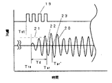
図2に、超音波送受信器8、9で送信、受信される信号を示す。矩形波19は、超音波送受信器8あるいは9に印加される送信信号を示す。正弦波状の信号20は、超音波送受信器8あるいは9で受信、増幅された受信信号を示す。一般的に時間計測の受信点は、受信信号がある閾値(破線21)を越えた次のゼロクロス点22を用いることが多い。この場合、送信信号の矩形波の立上がり時点Tstが送信開始時刻であり、ゼロクロス点22が受信時刻Tarなる。したがって、計測される超音波の伝搬時間Tprは、時刻Tarと時刻Tst間の時間となる。すなわち、Tpr=Tar−Tstとなる。
FIG. 2 shows signals transmitted and received by the
しかしながら、図2の受信信号20から明らかなように、伝搬してきた超音波が超音波送受信器8あるいは9によって受信される時刻は、受信信号20の先頭であるTreである。時刻Treと時刻Tarとの間の時間遅れTdは、受信側の超音波送受信器8または9に超音波が到着したあと、受信部15で受信されるまでの時間遅れTdと考えることができる。
However, as is apparent from the received
この時間遅れTdは、超音波送受信器8あるいは9の個々の特性に大きく依存している。したがって、上流側の超音波送受信器8から下流側の超音波送受信器9への超音波伝搬時間Tup−−>downの中には、受信側の超音波送受信器である下流側の超音波送受信器9の特性で決まるTd9が含まれる。また、下流側の超音波送受信器9から上流側の超音波送受信器8へ超音波伝搬時間 Tdown−−>upの中には、受信側の超音波送受信器である上流側の超音波送受信器8の特性で決まるTd8が含まれる。
This time delay Td greatly depends on the individual characteristics of the
このように、超音波送受信器の特性で決まる固有の時間Td8およびTd9を、オフセット値として予めオフセット値記憶手段18に記憶させておき、上記で説明した流量演算
時に、それぞれ計測された超音波伝搬時間Tup−−>downおよび Tdown−−>upから、それぞれのオフセット値Td8およびTd9を引き算処理することにより、より正確な超音波伝搬時間が得られることになり、より正確な流量値が演算される。本実施例の場合、上流側および下流側のオフセット値は、それぞれの超音波送受信器8および9で受信された受信波形の周期の2.5倍である。このように受信側の超音波送受信器のオフセット値を計測された超音波伝搬時間から差し引くことにより、流量値を高精度に演算することができ、精度の高い流量計測装置が実現できる。
In this way, the inherent times Td8 and Td9 determined by the characteristics of the ultrasonic transmitter / receiver are stored in advance in the offset
上記で説明したことを計算式で示すと、以下のようになる。 What has been described above can be expressed by the following formula.
すなわち、上記流速Vの式
V=[L/2×cos(θ)]×[(1/Tup−−>down)−(1/Tdown−−>up)]
において
Tup−−>down=Tud+Td9=Tud×[1+(Td9/Tud)]
Tdown−−>up=Tdu+Td8=Tdu×[1+(Td8/Tdu)]
である。
That is, the formula V = [L / 2 × cos (θ)] × [(1 / T up-> down )-(1 / T down-> up )]
T up- > down = Tud + Td9 = Tud × [1+ (Td9 / Tud)]
Tdown- > up = Tdu + Td8 = Tdu × [1+ (Td8 / Tdu)]
It is.
ここで、超音波が流体中を上流側から下流側へ、あるいは下流側から上流側への伝搬する時間をそれぞれ、Tud、Tduとした。また通常の場合、超音波が流体中を伝搬する時間 Tud、Tduは概ね100〜300μsec程度であり、Td8およびTd9なる時間は、超音波の周期の数倍程度の、1〜5μsec程度と十分小さい。従って、上式は次のように近似できる。 Here, the time during which the ultrasonic wave propagates in the fluid from the upstream side to the downstream side or from the downstream side to the upstream side is defined as Tud and Tdu, respectively. In normal cases, the times Tud and Tdu during which ultrasonic waves propagate in the fluid are approximately 100 to 300 μsec, and the times Td8 and Td9 are sufficiently small, approximately 1 to 5 μsec, which is several times the period of the ultrasonic waves. . Therefore, the above equation can be approximated as follows.
1/Tup−−>down=1/{Tud×[1+(Td9/Tud)]}
≒(1/Tud)×[1−(Td9/Tud)]
1/Tdown−−>up=1/{Tdu×[1+(Td8/Tdu)]}
≒(1/Tdu)×[1−(Td8/Tdu)]
これらを用いると、流体の流速Vは、以下のようになる。
1 / T up- > down = 1 / {Tud × [1+ (Td9 / Tud)]}
≒ (1 / Tud) x [1- (Td9 / Tud)]
1 / T down- > up = 1 / {Tdu × [1+ (Td8 / Tdu)]}
≒ (1 / Tdu) x [1- (Td8 / Tdu)]
When these are used, the flow velocity V of the fluid is as follows.
V=[L/2×cos(θ)]×[(1/Tud)×{1+(Td9/Tud)}
−(1/Tdu)×{1+(Td8/Tdu)}]
例えば、ここで流体の流れを止めた場合、超音波の上流側から下流側への伝搬時間Tudと下流側から上流側への伝搬時間Tduとは、超音波送受信器間の距離L、音速Cであるから、Tud=L/C、Tdu=L/Cとなり、全く等しくなる。その時間をT0とすると、その時の見かけの流速Vzは、
Vz=[L/2×cos(θ)]×[(1/T0)×{1+(Td9/T0)}
−(1/T0)×{1+(Td8/T0)}]
=[L/2×cos(θ)]×[(Td9−Td8)/T0^2]
となる。
V = [L / 2 × cos (θ)] × [(1 / Tud) × {1+ (Td9 / Tud)}
− (1 / Tdu) × {1+ (Td8 / Tdu)}]
For example, when the flow of fluid is stopped here, the propagation time Tud from the upstream side to the downstream side of the ultrasonic wave and the propagation time Tdu from the downstream side to the upstream side are the distance L between the ultrasonic transceivers and the sound velocity C Therefore, Tud = L / C and Tdu = L / C, which are completely equal. Assuming that time is T0, the apparent flow velocity Vz at that time is
Vz = [L / 2 × cos (θ)] × [(1 / T0) × {1+ (Td9 / T0)}
− (1 / T0) × {1+ (Td8 / T0)}]
= [L / 2 × cos (θ)] × [(Td9−Td8) / T0 ^ 2]
It becomes.
ここで、L、θは、流路により固定される定数となり、一定値と考えることができる。また、時間T0も、超音波の音速Cが決まると決定される値となり、固定値と考えることができる。このことは、超音波送受信器のオフセット値、Td8、Td9が決まればVz値が決定されることを示している。 Here, L and θ are constants fixed by the flow path, and can be considered as constant values. The time T0 is also a value determined when the ultrasonic sound velocity C is determined, and can be considered as a fixed value. This indicates that the Vz value is determined when the offset values Td8 and Td9 of the ultrasonic transceiver are determined.
このように、超音波送受信器固有の値Td9とTd8との差がある場合、流体の流れが、ゼロであっても、見かけ上、上記のような流速Vzが発生する。この流速Vzに流路の断面積を乗算すると、見掛けの流量としてのオフセット流量Qzが得られる。予めこの値Qzをオフセット値として記憶し、上記で演算した流量値Qcalを補正してもよい。 Thus, when there is a difference between the values Td9 and Td8 unique to the ultrasonic transmitter / receiver, the flow velocity Vz as described above appears even if the fluid flow is zero. When this flow velocity Vz is multiplied by the cross-sectional area of the flow path, an offset flow rate Qz as an apparent flow rate is obtained. This value Qz may be stored in advance as an offset value, and the flow rate value Qcal calculated above may be corrected.
以上説明したように、オフセット値を記憶していることにより、正確な流量値を演算することができる。 As described above, by storing the offset value, an accurate flow rate value can be calculated.
(実施の形態2)
図3を用いて、超音波送受信器のオフセット値である受信信号の周期を求める方法を説明する。図3は、図2で示した上流側あるいは下流側の超音波送受信器8または9での受信された受信信号20を示す。通常の場合、閾値(破線21)を越えた次のゼロクロス点22の時刻Tarを受信時刻とするが、オフセット値を計測しようとする場合には、閾値を越えた2つめのゼロクロス点23を受信時刻 Tar’として計測し、その差Tar’−Tarを受信信号の1周期として演算する。または、閾値(破線21)を大きくし、新たな閾値として、ゼロクロス点Tar’を計測しても良い(図示せず)。
(Embodiment 2)
A method for obtaining the period of the received signal, which is an offset value of the ultrasonic transceiver, will be described with reference to FIG. FIG. 3 shows a received
また、受信信号の増幅率を小さくし、閾値(破線21)をそのままにし、受信信号20を全体的に振幅が小さくなるようにし、閾値(破線21)を超えた次のゼロクロス点が、計測しようとするゼロクロス点23とし、時刻 Tar’を計測することもできる。
Further, the amplification factor of the received signal is decreased, the threshold value (broken line 21) is left as it is, the amplitude of the received
以上説明したように、計測のたびに、受信信号の周期を計測し、その2.5倍をオフセット値とすることにより、常に正確な流量値を演算することができる。 As described above, the accurate flow rate value can always be calculated by measuring the period of the received signal every time measurement is performed and setting the 2.5 times as the offset value.
(実施の形態3)
図4を用いて実施の形態3を説明する。実施の形態1と異なるところは、流体の温度検出手段、流体の種類検出手段あるいは流体の圧力検出手段などの環境変化検出手段24を設けたところである。このため、環境変化検出手段24により流体の温度、種類あるいは圧力が変化し、オフセット値が変化したと考えられる時のみ、上記実施の形態2で示した上流側および下流側の超音波送受信器8、9で受信される受信信号の周期を計測し、その値をオフセセット値とすることにより、効率よくオフセット値を更新することができる。
(Embodiment 3)
The third embodiment will be described with reference to FIG. The difference from the first embodiment is that an environmental change detection means 24 such as a fluid temperature detection means, a fluid type detection means or a fluid pressure detection means is provided. For this reason, only when it is considered that the temperature, type, or pressure of the fluid has changed due to the environment change detection means 24 and the offset value has changed, the upstream and downstream
従って、流量演算の度に、いつもオフセット値を計測する必要がなく、効率よくオフセット値を更新することができ、計測時間を短縮することができる。なお、これらの環境変化要因の中でオフセット値を最も大きく変動させるのは、流体の温度であった。従って、少なくとも温度検出手段で環境変化検出手段24を構成するのが最も有効である。
Therefore, it is not always necessary to measure the offset value every time the flow rate is calculated, the offset value can be updated efficiently, and the measurement time can be shortened. Of these environmental change factors, the largest fluctuation in the offset value was the temperature of the fluid. Therefore, it is most effective to configure the environment
(実施の形態4)
実施の形態3において、流体の温度検出手段を設けたが、流体中を伝搬する超音波の伝搬速度から流体の温度を検出する方法について説明する。この場合には、環境変化検出手段24としての温度検出が不要となり、超音波の伝播時間さえ計測できればから流体の温度を検出することができ、流量計測装置の構成が簡単になる。
(Embodiment 4)
In the third embodiment, although the fluid temperature detection means is provided, a method for detecting the fluid temperature from the propagation velocity of the ultrasonic wave propagating in the fluid will be described. In this case, it is not necessary to detect the temperature as the environment
実施の形態1において、超音波の伝搬速度、音速Cは、次式で計算されることを示した。すなわち、
C=(L/2)×[(1/Tup−−>down)+(1/Tdown−−>up)]
である。
In the first embodiment, it has been shown that the ultrasonic wave propagation velocity and the sound velocity C are calculated by the following equations. That is,
C = (L / 2) × [(1 / T up-> down ) + (1 / T down-> up )]
It is.
このように、超音波の伝搬時間Tup−−>downおよびTdown−−>upを計測することにより超音波の伝搬速度Cを検出することができる。例えば、流体が空気である場合、空気中の音速Cairは、空気の温度をTair[℃]とすると、音速Cair=341.45+0.607×Tair[m/sec]で示される。したがって、音速Cairが計測できれば、空気の温度Tairを計算することができる。また、流体が、水
である場合には、水温をTwaterとすると、水中の音速Cwater=1500+25×Twater[m/sec]で示されるから、音速Cwaterが計測できれば、水温Twaterが計算できる。
In this way, the ultrasonic wave propagation speed C can be detected by measuring the ultrasonic wave propagation times T up-> down and T down-> up . For example, when the fluid is air, the sound velocity Cair in the air is represented by the sound velocity Cair = 341.45 + 0.607 × Tair [m / sec], where the temperature of the air is Tair [° C.]. Therefore, if the sound velocity Cair can be measured, the air temperature Tair can be calculated. In addition, when the fluid is water, if the water temperature is Twater, the underwater sound velocity Cwater = 1500 + 25 × Twater [m / sec] is indicated, so if the sound velocity Cwater can be measured, the water temperature Twater can be calculated.
このように、環境変化検出手段としての温度検出手段を設けることなく、流体の温度が検出できることになり、流量計測装置の構成が簡単になる。しかも、流速Vを計測するのと同様にして、時間計測手段で、流体の温度を計測できるので、構成が非常に簡単になる。 In this way, the temperature of the fluid can be detected without providing temperature detecting means as environmental change detecting means, and the configuration of the flow rate measuring device is simplified. In addition, since the temperature of the fluid can be measured by the time measuring means in the same manner as when the flow velocity V is measured, the configuration becomes very simple.
(実施の形態5)
図1および図5を用いて実施の形態5を説明する。図5は、超音波送受信器8、9の受信信号から計測した受信周期に基づくオフセット値、Td8とTd9との差を横軸に、縦軸に見掛けの流量としてのオフセット流量Qzとの関係を示す。同図に見られるように、この関係は一次関数sで近似される関係を示し、
Qz=A×(Td8−Td9)+B
で表現される。ここで、A、Bは予め決められている定数である。
(Embodiment 5)
A fifth embodiment will be described with reference to FIGS. 1 and 5. FIG. 5 shows the relationship between the offset value based on the reception period measured from the reception signals of the
Qz = A × (Td8−Td9) + B
It is expressed by Here, A and B are predetermined constants.
例えば、このようなオフセット値、Td8およびTd9を有する超音波送受信器を備えた図1に示した流路を準備し、その上流および下流を閉止し、流れのない状態で流量値を演算させる。演算された流量値、Qzが零となるように定数Bを新たに求め、2つの定数A、Bを更新する(Aは、そのまま)。このようにして定数A、Bをオフセット値として記憶させる。このようにして、定数A、Bを決めることにより、安定で、正確な流量値を演算する流量計測装置を実現できる。 For example, the flow path shown in FIG. 1 provided with an ultrasonic transmitter / receiver having such offset values, Td8 and Td9, is prepared, the upstream and downstream are closed, and the flow rate value is calculated in the absence of flow. A constant B is newly obtained so that the calculated flow rate value Qz becomes zero, and the two constants A and B are updated (A is unchanged). In this way, the constants A and B are stored as offset values. Thus, by determining the constants A and B, it is possible to realize a flow rate measuring apparatus that calculates a stable and accurate flow rate value.
以上の説明から、本発明の実施の形態における流量計測装置によれば、次の効果が得られる。
(1)オフセット値を記憶しているので、安定で、正確な流量値を演算することができる。
(2)受信信号からオフセット値を計測することができるので、常に安定で、正確な流量値を演算できる。
(3)環境変化検出手段を有しているので、環境変化を検出した時のみ、オフセット値を計測すれば良く、効率よくオフセット値を更新することができる。
(4)超音波の伝搬時間から流体の温度を検出することができるので、構成が簡単な流量計測装置を実現することができる。
(5)予め流量のない状態で、オフセット値を更新するので、常に安定で、正確な流量計測装置を実現できる。
From the above description, according to the flow rate measuring apparatus in the embodiment of the present invention, the following effects can be obtained.
(1) Since the offset value is stored, a stable and accurate flow rate value can be calculated.
(2) Since the offset value can be measured from the received signal, the flow value can always be calculated stably and accurately.
(3) Since the environment change detecting means is provided, the offset value may be measured only when the environment change is detected, and the offset value can be updated efficiently.
(4) Since the temperature of the fluid can be detected from the propagation time of the ultrasonic wave, a flow measuring device with a simple configuration can be realized.
(5) Since the offset value is updated in a state where there is no flow rate in advance, a stable and accurate flow rate measuring device can be realized.
7 流路
8 上流側の超音波送受信器
9 下流側の超音波送受信器
13 送信手段
14 切換手段
15 受信手段
16 時間計測手段
17 流量演算手段
18 オフセット値記憶手段
19 送信波形
20 受信波形
21 閾値
24 環境変化検出手段
7 Flow
Claims (2)
Priority Applications (1)
| Application Number | Priority Date | Filing Date | Title |
|---|---|---|---|
| JP2006331554A JP2007064988A (en) | 2006-12-08 | 2006-12-08 | Flowmeter |
Applications Claiming Priority (1)
| Application Number | Priority Date | Filing Date | Title |
|---|---|---|---|
| JP2006331554A JP2007064988A (en) | 2006-12-08 | 2006-12-08 | Flowmeter |
Related Parent Applications (1)
| Application Number | Title | Priority Date | Filing Date |
|---|---|---|---|
| JP11316298A Division JPH11304559A (en) | 1998-04-23 | 1998-04-23 | Flow rate measuring apparatus |
Publications (2)
| Publication Number | Publication Date |
|---|---|
| JP2007064988A true JP2007064988A (en) | 2007-03-15 |
| JP2007064988A5 JP2007064988A5 (en) | 2009-04-02 |
Family
ID=37927316
Family Applications (1)
| Application Number | Title | Priority Date | Filing Date |
|---|---|---|---|
| JP2006331554A Pending JP2007064988A (en) | 2006-12-08 | 2006-12-08 | Flowmeter |
Country Status (1)
| Country | Link |
|---|---|
| JP (1) | JP2007064988A (en) |
Cited By (2)
| Publication number | Priority date | Publication date | Assignee | Title |
|---|---|---|---|---|
| JP2013210313A (en) * | 2012-03-30 | 2013-10-10 | Tokiko Techno Kk | Ultrasonic flowmeter |
| WO2014068952A1 (en) | 2012-11-05 | 2014-05-08 | パナソニック株式会社 | Flow rate measuring device and flow rate calculation method |
Citations (1)
| Publication number | Priority date | Publication date | Assignee | Title |
|---|---|---|---|---|
| JPH09133560A (en) * | 1995-11-09 | 1997-05-20 | Aichi Tokei Denki Co Ltd | Ultrasonic flowmeter |
-
2006
- 2006-12-08 JP JP2006331554A patent/JP2007064988A/en active Pending
Patent Citations (1)
| Publication number | Priority date | Publication date | Assignee | Title |
|---|---|---|---|---|
| JPH09133560A (en) * | 1995-11-09 | 1997-05-20 | Aichi Tokei Denki Co Ltd | Ultrasonic flowmeter |
Cited By (3)
| Publication number | Priority date | Publication date | Assignee | Title |
|---|---|---|---|---|
| JP2013210313A (en) * | 2012-03-30 | 2013-10-10 | Tokiko Techno Kk | Ultrasonic flowmeter |
| WO2014068952A1 (en) | 2012-11-05 | 2014-05-08 | パナソニック株式会社 | Flow rate measuring device and flow rate calculation method |
| US9638557B2 (en) | 2012-11-05 | 2017-05-02 | Panasonic Intellectual Property Management Co., Ltd. | Ultrasonic flowmeter having an arithmetic operation unit for calculating propagation time correction value |
Similar Documents
| Publication | Publication Date | Title |
|---|---|---|
| WO2011083766A1 (en) | Ultrasonic flowmeter | |
| JP2008134267A (en) | Ultrasonic flow measurement method | |
| JP5796154B2 (en) | Flow measuring device | |
| JP2007187506A (en) | Ultrasonic flowmeter | |
| JP4561088B2 (en) | Ultrasonic flow meter | |
| WO2014006881A1 (en) | Flow quantity measuring apparatus | |
| JPH11304559A (en) | Flow rate measuring apparatus | |
| JP5141613B2 (en) | Ultrasonic flow meter | |
| JP2007064988A (en) | Flowmeter | |
| JP2018138891A (en) | Ultrasonic flowmeter | |
| JP2007064988A5 (en) | ||
| JP4797515B2 (en) | Ultrasonic flow measuring device | |
| JP2011038870A (en) | Ultrasonic flow meter and flow rate measuring method using the same | |
| JP3624743B2 (en) | Ultrasonic flow meter | |
| CN109073430A (en) | Flow measurement device | |
| JP2005300244A (en) | Ultrasonic flow meter | |
| JP2008185441A (en) | Ultrasonic flowmeter | |
| JP7203352B2 (en) | ultrasonic flow meter | |
| JP7320776B2 (en) | ultrasonic flow meter | |
| JP2012107874A (en) | Ultrasonic flowmeter | |
| JP3622613B2 (en) | Ultrasonic flow meter | |
| JP6767628B2 (en) | Flow measuring device | |
| JP3672997B2 (en) | Correlation flowmeter and vortex flowmeter | |
| JP4888464B2 (en) | Flow measuring device | |
| JP2010151583A (en) | Ultrasonic flow measuring device |
Legal Events
| Date | Code | Title | Description |
|---|---|---|---|
| A621 | Written request for application examination |
Free format text: JAPANESE INTERMEDIATE CODE: A621 Effective date: 20061208 |
|
| A521 | Request for written amendment filed |
Free format text: JAPANESE INTERMEDIATE CODE: A523 Effective date: 20090212 |
|
| RD01 | Notification of change of attorney |
Free format text: JAPANESE INTERMEDIATE CODE: A7421 Effective date: 20091127 |
|
| A131 | Notification of reasons for refusal |
Free format text: JAPANESE INTERMEDIATE CODE: A131 Effective date: 20100126 |
|
| A521 | Request for written amendment filed |
Free format text: JAPANESE INTERMEDIATE CODE: A523 Effective date: 20100317 |
|
| A02 | Decision of refusal |
Free format text: JAPANESE INTERMEDIATE CODE: A02 Effective date: 20100413 |