JP2007060632A - Communication system, communication apparatus and method, and program - Google Patents
Communication system, communication apparatus and method, and program Download PDFInfo
- Publication number
- JP2007060632A JP2007060632A JP2006174774A JP2006174774A JP2007060632A JP 2007060632 A JP2007060632 A JP 2007060632A JP 2006174774 A JP2006174774 A JP 2006174774A JP 2006174774 A JP2006174774 A JP 2006174774A JP 2007060632 A JP2007060632 A JP 2007060632A
- Authority
- JP
- Japan
- Prior art keywords
- communication
- setting
- unit
- attribute information
- information
- Prior art date
- Legal status (The legal status is an assumption and is not a legal conclusion. Google has not performed a legal analysis and makes no representation as to the accuracy of the status listed.)
- Pending
Links
- 230000006854 communication Effects 0.000 title claims abstract description 994
- 238000004891 communication Methods 0.000 title claims abstract description 968
- 238000000034 method Methods 0.000 title claims description 281
- 238000012545 processing Methods 0.000 claims abstract description 315
- 230000005540 biological transmission Effects 0.000 claims description 463
- 230000008569 process Effects 0.000 claims description 221
- 230000035945 sensitivity Effects 0.000 claims description 56
- 230000008859 change Effects 0.000 claims description 43
- 238000004422 calculation algorithm Methods 0.000 claims description 28
- 230000004044 response Effects 0.000 claims description 13
- 230000006870 function Effects 0.000 description 95
- 238000010586 diagram Methods 0.000 description 60
- 238000005457 optimization Methods 0.000 description 51
- 239000004020 conductor Substances 0.000 description 39
- 238000012790 confirmation Methods 0.000 description 32
- 230000008878 coupling Effects 0.000 description 20
- 238000010168 coupling process Methods 0.000 description 20
- 238000005859 coupling reaction Methods 0.000 description 20
- 238000001228 spectrum Methods 0.000 description 15
- 238000002789 length control Methods 0.000 description 12
- 239000003990 capacitor Substances 0.000 description 9
- 238000009826 distribution Methods 0.000 description 8
- 230000002829 reductive effect Effects 0.000 description 8
- 230000008054 signal transmission Effects 0.000 description 8
- 238000003860 storage Methods 0.000 description 8
- 238000004364 calculation method Methods 0.000 description 7
- 238000003672 processing method Methods 0.000 description 7
- 230000000694 effects Effects 0.000 description 6
- 238000011156 evaluation Methods 0.000 description 6
- 239000000284 extract Substances 0.000 description 6
- 239000004065 semiconductor Substances 0.000 description 6
- 238000013478 data encryption standard Methods 0.000 description 5
- 230000005684 electric field Effects 0.000 description 5
- 230000007423 decrease Effects 0.000 description 4
- 239000004973 liquid crystal related substance Substances 0.000 description 4
- 230000010355 oscillation Effects 0.000 description 4
- 230000007480 spreading Effects 0.000 description 4
- 238000003892 spreading Methods 0.000 description 4
- 230000003068 static effect Effects 0.000 description 4
- 238000001514 detection method Methods 0.000 description 3
- 238000004070 electrodeposition Methods 0.000 description 3
- 238000005401 electroluminescence Methods 0.000 description 3
- XEEYBQQBJWHFJM-UHFFFAOYSA-N Iron Chemical compound [Fe] XEEYBQQBJWHFJM-UHFFFAOYSA-N 0.000 description 2
- FAPWRFPIFSIZLT-UHFFFAOYSA-M Sodium chloride Chemical compound [Na+].[Cl-] FAPWRFPIFSIZLT-UHFFFAOYSA-M 0.000 description 2
- 230000009471 action Effects 0.000 description 2
- 239000008186 active pharmaceutical agent Substances 0.000 description 2
- 238000013459 approach Methods 0.000 description 2
- 230000006399 behavior Effects 0.000 description 2
- 230000007175 bidirectional communication Effects 0.000 description 2
- 238000001914 filtration Methods 0.000 description 2
- 230000010365 information processing Effects 0.000 description 2
- 238000012423 maintenance Methods 0.000 description 2
- 238000004519 manufacturing process Methods 0.000 description 2
- 239000000463 material Substances 0.000 description 2
- 229910052751 metal Inorganic materials 0.000 description 2
- 239000002184 metal Substances 0.000 description 2
- 230000003287 optical effect Effects 0.000 description 2
- 230000010287 polarization Effects 0.000 description 2
- 230000000717 retained effect Effects 0.000 description 2
- 238000004088 simulation Methods 0.000 description 2
- 239000000126 substance Substances 0.000 description 2
- 230000001960 triggered effect Effects 0.000 description 2
- XLYOFNOQVPJJNP-UHFFFAOYSA-N water Substances O XLYOFNOQVPJJNP-UHFFFAOYSA-N 0.000 description 2
- RYGMFSIKBFXOCR-UHFFFAOYSA-N Copper Chemical compound [Cu] RYGMFSIKBFXOCR-UHFFFAOYSA-N 0.000 description 1
- 108700027089 Hirudo medicinalis macrolin Proteins 0.000 description 1
- 208000007400 Relapsing-Remitting Multiple Sclerosis Diseases 0.000 description 1
- 229910052782 aluminium Inorganic materials 0.000 description 1
- XAGFODPZIPBFFR-UHFFFAOYSA-N aluminium Chemical compound [Al] XAGFODPZIPBFFR-UHFFFAOYSA-N 0.000 description 1
- 230000001413 cellular effect Effects 0.000 description 1
- 239000002131 composite material Substances 0.000 description 1
- 238000004590 computer program Methods 0.000 description 1
- 229910052802 copper Inorganic materials 0.000 description 1
- 239000010949 copper Substances 0.000 description 1
- 238000011161 development Methods 0.000 description 1
- 239000003989 dielectric material Substances 0.000 description 1
- 239000003792 electrolyte Substances 0.000 description 1
- 238000005516 engineering process Methods 0.000 description 1
- 239000010419 fine particle Substances 0.000 description 1
- 239000011521 glass Substances 0.000 description 1
- 230000006698 induction Effects 0.000 description 1
- 238000009434 installation Methods 0.000 description 1
- 239000012212 insulator Substances 0.000 description 1
- 230000002452 interceptive effect Effects 0.000 description 1
- 229910052742 iron Inorganic materials 0.000 description 1
- 239000000203 mixture Substances 0.000 description 1
- 230000000644 propagated effect Effects 0.000 description 1
- 230000002441 reversible effect Effects 0.000 description 1
- 239000005060 rubber Substances 0.000 description 1
- 239000011780 sodium chloride Substances 0.000 description 1
- 239000000758 substrate Substances 0.000 description 1
- 230000002123 temporal effect Effects 0.000 description 1
- 238000012546 transfer Methods 0.000 description 1
Images


Classifications
-
- H—ELECTRICITY
- H04—ELECTRIC COMMUNICATION TECHNIQUE
- H04B—TRANSMISSION
- H04B13/00—Transmission systems characterised by the medium used for transmission, not provided for in groups H04B3/00 - H04B11/00
- H04B13/005—Transmission systems in which the medium consists of the human body
Abstract
Description
本発明は、通信システム、通信装置および方法、並びにプログラムに関し、特に、通信処理の用途に応じて、より適した通信設定で通信を行うことができるようにする通信システム、通信装置および方法、並びにプログラムに関する。 The present invention relates to a communication system, a communication apparatus and method, and a program, and in particular, a communication system, a communication apparatus and method, and a communication system that can perform communication with a more suitable communication setting depending on the use of communication processing. Regarding the program.
従来、通信においては、各通信装置や通信状況等によって、その通信の精度は大きく影響される。例えば、通信状況が非常に悪く、通信相手より送信された情報の正常な受信が困難である場合に、通信速度がより高速に設定されたり、受信感度や送信パワーを抑制されたりすると、さらに通信エラー率が上昇し、正常な通信がさらに困難になる。 Conventionally, in communication, the accuracy of communication is greatly affected by each communication device, communication status, and the like. For example, if the communication status is very bad and it is difficult to receive information transmitted from the communication partner normally, if the communication speed is set higher or the reception sensitivity and transmission power are suppressed, further communication The error rate increases and normal communication becomes more difficult.
そこで、受信状況に応じて送信電力の強弱を調節する方法が考えられている(例えば、特許文献1参照)。 Therefore, a method of adjusting the strength of transmission power in accordance with the reception status has been considered (for example, see Patent Document 1).
ところで、近年においては、情報処理技術の発達に伴い、近距離無線通信を利用して各種サービスを提供する通信システムが普及し始めており、例えば、公共交通機関の乗車運賃の支払い、商店における商品やチケットの購入、社員証や入館証等のような個人認証、ドア開錠等のセキュリティシステム、社員食堂での支払い等、様々な用途に利用されている。 By the way, in recent years, with the development of information processing technology, communication systems that provide various services using short-range wireless communication have begun to spread. For example, payment of boarding fares for public transportation, products in stores, It is used for various purposes, such as ticket purchase, personal authentication such as employee ID card or entrance card, security system such as door unlocking, payment at employee cafeteria.
このようなシステムにおいて、ユーザは、例えばICカードのような、近距離無線通信を行う通信機能と、個人情報や所持金情報等を記憶する記録媒体とを有する携帯用デバイスを携帯し、料金の支払いや個人認証等のサービスを受ける際に、その携帯用デバイスを、サービス提供者側のリーダライタに近接または接触させ、通信させることにより、サービスを受けることができる。 In such a system, a user carries a portable device having a communication function for performing short-distance wireless communication, such as an IC card, and a recording medium for storing personal information, personal belongings information, etc. When receiving a service such as payment or personal authentication, the portable device can receive the service by bringing the portable device close to or in contact with the reader / writer on the service provider side and communicating.
しかしながら、上述したように、通信状況が常に最適であるとは限らない。従って、各種の条件によっては、サービスの提供に必要な通信処理が正常に行われない恐れがある。 However, as described above, the communication status is not always optimal. Therefore, depending on various conditions, there is a possibility that communication processing necessary for providing the service may not be performed normally.
これに対して、例えば、上述した特許文献1に記載の方法を用いて、受信状況に応じて送信電力の強弱を調節することも考えられるが、上述したように、近距離無線通信は様々な用途に利用されているため、その用途によっては通信環境に関わらず処理速度を低下させる必要があることも考えられる。また、通信処理の評価要素として、処理速度以外にも、例えば、通信範囲や消費電力等もあり、必ずしも、高速に通信を行うことが望ましいとは限らない。
On the other hand, for example, it is conceivable to adjust the strength of the transmission power in accordance with the reception situation using the method described in
本発明はこのような状況に鑑みてなされたものであり、通信処理の用途に応じて、より適した通信設定で通信を行うことができるようにするものである。 The present invention has been made in view of such a situation, and makes it possible to perform communication with a more suitable communication setting according to the use of communication processing.
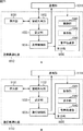
本発明の一側面の通信システムは、通信媒体を介して通信を行う第1の通信装置と第2の通信装置を備える通信システムであって、前記第1の通信装置は、前記第1の通信装置の機能および用途に関する情報である第1の属性情報を保持する第1の保持手段と、前記第1の保持手段に保持されている第1の属性情報、および、前記第2の通信装置が保持する前記第2の通信装置の機能および用途に関する情報である第2の属性情報を、前記第2の通信装置と共有する第1の共有手段と、前記第1の共有手段により共有された前記第2の属性情報に基づいて、前記通信の設定を行う第1の設定手段と、記第1の設定手段による前記通信の設定の結果に基づいて、前記通信を制御する第1の制御手段とを備え、前記第2の通信装置は、前記第2の属性情報を保持する第2の保持手段と、前記第2の保持手段により保持されている第2の属性情報、および、前記第1の通信装置の前記第1の保持手段により保持されている前記第1の属性情報を、前記第1の通信装置と共有する第2の共有手段と、前記第2の共有手段により共有された前記第1の属性情報に基づいて、前記通信の設定を行う第2の設定手段と、前記第2の設定手段による前記通信の設定の結果に基づいて、前記通信を制御する第2の制御手段とを備える。 A communication system according to one aspect of the present invention is a communication system including a first communication device and a second communication device that perform communication via a communication medium, and the first communication device includes the first communication device. First holding means for holding first attribute information that is information relating to the function and use of the apparatus, first attribute information held in the first holding means, and the second communication device The second attribute information, which is information related to the function and application of the second communication device to be held, is shared with the second communication device, and the first sharing unit shares the second attribute information. A first setting unit configured to set the communication based on second attribute information; a first control unit configured to control the communication based on a result of the communication setting performed by the first setting unit; The second communication device includes the second communication device. Second holding means for holding sex information, second attribute information held by the second holding means, and the first holding means of the first communication device A second sharing unit that shares first attribute information with the first communication device, and a second unit that sets the communication based on the first attribute information shared by the second sharing unit. 2 setting means and second control means for controlling the communication based on the result of the communication setting by the second setting means.
本発明の一側面においては、第1の通信装置が保持する第1の通信装置の機能および用途に関する情報である第1の属性情報と第2の通信装置が保持する第2の通信装置の機能および用途に関する情報である第2の属性情報とが共有され、第1の通信装置においては、共有された第2の属性情報に基づいて通信が制御され、第2の通信装置においては、共有された第1の属性情報に基づいて通信が制御される。 In one aspect of the present invention, the first attribute information, which is information related to the function and application of the first communication device held by the first communication device, and the function of the second communication device held by the second communication device. And the second attribute information that is information relating to the use, the first communication device controls communication based on the shared second attribute information, and the second communication device shares the second attribute information. Communication is controlled based on the first attribute information.
本発明の他の側面は、通信媒体を介して他の通信装置と通信を行う通信装置であって、前記他の通信装置の機能および用途に関する情報である第1の属性情報を取得する取得手段と、前記取得手段により取得された前記第1の属性情報に基づいて、前記通信の設定を行う設定手段と、前記設定手段による前記通信の設定の結果に基づいて、前記通信を制御する制御手段とを備える通信装置である。 Another aspect of the present invention is a communication device that communicates with another communication device via a communication medium, and obtains first attribute information that is information relating to the function and application of the other communication device. And setting means for setting the communication based on the first attribute information acquired by the acquiring means, and control means for controlling the communication based on a result of the communication setting by the setting means A communication device.
前記第1の属性情報は、前記他の通信装置の処理速度に関する情報、送信パワーに関する情報、受信感度に関する情報、電源の有無に関する情報、および電源の状態に関する情報のうち、少なくとも1つを含む、前記他の通信装置のハードウェアに関する情報を含むようにすることができる。 The first attribute information includes at least one of information on a processing speed of the other communication device, information on transmission power, information on reception sensitivity, information on the presence / absence of a power source, and information on a state of a power source, Information on hardware of the other communication device may be included.
前記第1の属性情報は、前記他の通信装置が実行するソフトウェアに関する情報を含むようにすることができる。 The first attribute information may include information related to software executed by the other communication device.
前記他の通信装置に対して前記第1の属性情報を要求する要求手段をさらに備え、前記取得手段は、前記通信装置が前記要求手段による要求に対して送信した前記第1の属性情報を取得することができる。 Requesting means for requesting the first attribute information from the other communication device is further provided, wherein the obtaining means obtains the first attribute information transmitted by the communication device in response to the request by the requesting means. can do.
前記設定手段は、前記通信の設定として、処理速度、送信パワー、受信感度、および前記他の通信装置に対する電力供給制御のうち、少なくとも1つの設定を行うことができる。 The setting means can set at least one of processing speed, transmission power, reception sensitivity, and power supply control for the other communication device as the communication setting.
前記第1の属性情報より前記通信の設定を行うためのテーブル情報である設定テーブルを保持するテーブル保持手段をさらに備え、前記設定手段は、前記テーブル保持手段に保持される前記テーブル情報を用いて前記通信の設定を行うことができる。 Table holding means for holding a setting table that is table information for setting the communication based on the first attribute information is further provided, and the setting means uses the table information held in the table holding means. The communication setting can be performed.
前記取得手段により取得された前記第1の属性情報に基づいて、前記他の通信装置が前記通信に関する設定を変更可能か否かを判定する設定変更可否判定手段をさらに備え、前記設定手段は、前記設定変更可否判定手段による判定結果に基づいて前記通信の設定を行うことができる。 Based on the first attribute information acquired by the acquisition means, further comprises a setting change enable / disable determining means for determining whether or not the other communication device can change the settings related to the communication, the setting means comprising: The communication can be set based on a determination result by the setting change permission determination unit.
前記設定手段による前記通信の設定の結果に関する情報を表示する表示手段をさらに備えるようにすることができる。 The information processing apparatus may further include display means for displaying information related to the result of the communication setting by the setting means.
前記第1の属性情報は、前記他の通信装置の、暗号処理のアルゴリズムに関する情報、暗号処理の処理段数関する情報、および暗号鍵の鍵長に関する情報のうち、少なくとも1つを含むようにすることができる。 The first attribute information includes at least one of information relating to an encryption processing algorithm, information relating to the number of stages of encryption processing, and information relating to the key length of the encryption key of the other communication device. Can do.
前記第1の属性情報は、前記他の通信装置の動作クロックに関する情報を含むようにすることができる。 The first attribute information may include information related to an operation clock of the other communication device.
前記第1の属性情報は、前記他の通信装置のハードウェア機能に関する情報を含むようにすることができる。 The first attribute information may include information related to hardware functions of the other communication device.
前記通信装置の機能および用途に関する情報である第2の属性情報を保持する属性情報保持手段と、前記属性情報保持手段により保持されている前記第2の属性情報を前記他の通信装置に供給する供給手段とをさらに備えるようにすることができる。 Attribute information holding means for holding second attribute information, which is information relating to the function and application of the communication device, and the second attribute information held by the attribute information holding means is supplied to the other communication device. And a supply means.
前記第2の属性情報は、前記通信装置の処理速度に関する情報、送信パワーに関する情報、受信感度に関する情報、電源の有無に関する情報、および電源の状態に関する情報のうち、少なくとも1つを含む、前記通信装置のハードウェアに関する情報を含むようにすることができる。 The second attribute information includes at least one of information on a processing speed of the communication device, information on transmission power, information on reception sensitivity, information on presence / absence of a power source, and information on a state of a power source, Information about the hardware of the device may be included.
前記第2の属性情報は、前記他の通信装置が実行するソフトウェアに関する情報を含むようにすることができる。 The second attribute information may include information related to software executed by the other communication device.
前記他の通信装置からの前記第2の属性情報の要求を受け付ける要求受付手段をさらに備え、前記供給手段は、前記要求受付手段により前記要求が受け付けられたとき、前記第2の属性情報を前記他の通信装置に供給することができる。 The apparatus further comprises request accepting means for accepting a request for the second attribute information from the other communication device, and the supply means receives the second attribute information when the request is accepted by the request accepting means. It can be supplied to other communication devices.
前記第2の属性情報は、前記通信装置の暗号処理のアルゴリズムに関する情報、暗号処理の処理段数関する情報、および暗号鍵の鍵長に関する情報のうち、少なくとも1つを含むようにすることができる。 The second attribute information may include at least one of information relating to an encryption processing algorithm of the communication device, information relating to the number of encryption processing steps, and information relating to the key length of the encryption key.
前記第2の属性情報は、前記通信装置の動作クロックに関する情報を含むようにすることができる。 The second attribute information may include information related to an operation clock of the communication device.
前記第2の属性情報は、前記通信装置のハードウェア機能に関する情報を含むようにすることができる。 The second attribute information may include information related to hardware functions of the communication device.
前記通信装置の機能および用途に関する情報である第2の属性情報を保持する属性情報保持手段と、前記設定手段による前記通信の設定の結果を前記他の通信装置に供給する供給手段とを備え、前記設定手段は、前記取得手段により取得された前記第1の属性情報、および、前記属性情報保持手段により保持されている前記第2の属性情報に基づいて、前記通信装置に関する前記通信の設定、および、前記他の通信装置に関する前記通信の設定を行い、前記供給手段は、少なくとも前記他の通信装置に関する前記通信の設定の結果を前記他の通信装置に供給することができる。 Attribute information holding means for holding second attribute information that is information relating to the function and use of the communication device, and supply means for supplying the result of the communication setting by the setting means to the other communication device, The setting unit is configured to set the communication related to the communication device based on the first attribute information acquired by the acquiring unit and the second attribute information held by the attribute information holding unit. And the said communication setting regarding the said other communication apparatus is performed, The said supply means can supply the result of the said communication setting regarding the said other communication apparatus at least to the said other communication apparatus.
前記他の通信装置より供給される、前記通信装置に関する前記通信の設定結果を取得する設定結果取得手段をさらに備え、前記設定手段は、前記設定結果取得手段により取得された、前記通信装置に関する前記通信の設定結果に基づいて、前記通信の設定を行うようにすることができる。 The apparatus further comprises setting result acquisition means for acquiring a setting result of the communication related to the communication apparatus supplied from the other communication apparatus, and the setting means is related to the communication apparatus acquired by the setting result acquisition means. The communication setting can be performed based on the communication setting result.
本発明の他の側面は、通信媒体を介して他の通信装置と通信を行う通信装置の通信方法、または、通信媒体を介して他の通信装置と通信を行う処理をコンピュータに実行させるプログラムにおいて、前記他の通信装置の機能および用途に関する情報である属性情報を取得し、取得された前記属性情報に基づいて、前記通信の設定を行い、前記通信処理の設定の結果に基づいて、前記通信を制御するステップを含む通信方法、またはプログラムである。 Another aspect of the present invention relates to a communication method of a communication device that communicates with another communication device via a communication medium, or a program that causes a computer to execute a process of communicating with another communication device via a communication medium. , Acquiring attribute information which is information on the function and use of the other communication device, setting the communication based on the acquired attribute information, and setting the communication based on the setting result of the communication process It is a communication method or program including the step which controls.
本発明の他の側面においては、前記他の通信装置の機能および用途に関する情報である属性情報が取得され、取得された前記属性情報に基づいて前記通信の設定が行われ、前記通信処理の設定の結果に基づいて前記通信が制御される。 In another aspect of the present invention, attribute information that is information related to the function and application of the other communication device is acquired, the communication setting is performed based on the acquired attribute information, and the communication processing setting is performed. The communication is controlled based on the result.
本発明の一側面によれば、通信を行うことができる。特に、通信処理の用途に応じて、より適した通信設定で通信を行うことができる。 According to one aspect of the present invention, communication can be performed. In particular, communication can be performed with a more suitable communication setting according to the use of communication processing.
以下、本発明の実施の形態について図を参照して説明する。最初に、図1乃至図33を参照して、本発明を適用する通信システムの例として、物理的な基準点経路を不要とし、通信信号伝達経路のみによる通信を実現することによって、利用環境の制約を受けない通信システムについて説明する。 Hereinafter, embodiments of the present invention will be described with reference to the drawings. First, referring to FIG. 1 to FIG. 33, as an example of a communication system to which the present invention is applied, a physical reference point path is not required and communication using only a communication signal transmission path is realized. A communication system that is not restricted will be described.
図1は、物理的な基準点経路を用いずに通信信号伝達経路のみによって通信を行う通信システムの一実施形態に係る構成例を示す図である。 FIG. 1 is a diagram illustrating a configuration example according to an embodiment of a communication system that performs communication using only a communication signal transmission path without using a physical reference point path.
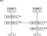
図1において、通信システム100は、送信装置110、受信装置120、および通信媒体130により構成され、送信装置110と受信装置120が通信媒体130を介して信号を送受信するシステムである。つまり、通信システム100において、送信装置110より送信された信号は、通信媒体130を介して伝送され、受信装置120により受信される。
In FIG. 1, the communication system 100 includes a
送信装置110は、送信信号電極111、送信基準電極112、および送信部113を有している。送信信号電極111は、通信媒体130を介して伝送させる信号を送信するために設けられた電極対の一方の電極であり、その電極対の他方の電極である送信基準電極112よりも通信媒体130に対して静電結合が強くなるように設けられる。送信部113は、送信信号電極111と送信基準電極112との間に設けられ、これらの電極間に受信装置120へ伝達したい電気信号(電位差)を与える。
The
受信装置120は、受信信号電極121、受信基準電極122、および受信部123を有している。受信信号電極121は、通信媒体130を介して伝送される信号を受信するために設けられた電極対の一方の電極であり、その電極対の他方の電極である受信基準電極122よりも通信媒体130に対して静電結合が強くなるように設けられる。受信部123は、受信信号電極121と受信基準電極122との間に設けられ、通信媒体130を介して伝送される信号によってこれらの電極間に生じた電気信号(電位差)を検知し、その電気信号を所望の電気信号に変換し、送信装置110の送信部113で生成された電気信号を復元する。
The
通信媒体130は、電気信号を伝達可能な物理的特性を有する物質、例えば、導電体や誘電体等により構成される。例えば、通信媒体130は、銅、鉄、またはアルミ等の金属に代表される導電体、純水、ゴム、ガラス等に代表される誘電体、または、これらの複合体である生体や、食塩水等の電解液のように、導体としての性質と誘電体としての性質を併せ持つ素材により構成される。また、この通信媒体130の形状はどのようなものであってもよく、例えば、線状、板状、球状、角柱、または円柱等であってもよく、さらにこれら以外の任意の形状であってもよい。
The
このような通信システム100において、はじめに、各電極と、通信媒体または装置周辺空間との関係について説明する。なお、以下において、説明の便宜上、通信媒体130が完全導体であるものとする。また、送信信号電極111と通信媒体130との間、および、受信信号電極121と通信媒体130との間には空間が存在し、電気的な結合はないものとする。すなわち、送信信号電極111または受信信号電極121と、通信媒体130との間には、それぞれ、静電容量が形成される。
In such a communication system 100, first, the relationship between each electrode and the communication medium or the space around the apparatus will be described. In the following, for convenience of explanation, it is assumed that the
また、送信基準電極112は送信装置110周辺の空間に向くように設けられており、受信基準電極122は受信装置120周辺の空間に向くように設けられている。一般的に、導体球が空間に存在する場合、その導体球と空間との間には静電容量が形成される。例えば、導体の形状を半径r[m]の球としたとき、その静電容量Cは、以下の式(1)のように求められる。
The
![]()
![]()
式(1)において、πは円周率を示す。また、εは誘電率を示し、以下の式(2)のように求められる。 In the formula (1), π represents a circumference ratio. Further, ε represents a dielectric constant and is obtained as in the following formula (2).
![]()
![]()
ただし、式(2)において、ε0は、真空中の誘電率を示し、8.854×10⁻¹²[F/m]である。また、εrは比誘電率を示し、真空の誘電率ε0に対する比率を示す。 However, in Formula (2), ε 0 indicates a dielectric constant in a vacuum, and is 8.854 × 10 −12 [F / m]. Further, ε r represents a relative dielectric constant, and represents a ratio to a vacuum dielectric constant ε 0 .
上述した式(1)に示されるように半径rが大きい程、静電容量Cは大きくなる。なお、球以外の複雑な形状の導体の静電容量Cの大きさは、上述した式(1)のように、簡単に表現することはできないが、その導体の表面積の大きさに応じて変化することは明らかである。 As shown in the above formula (1), the larger the radius r, the larger the capacitance C. In addition, although the magnitude | size of the electrostatic capacitance C of a conductor of complicated shape other than a sphere cannot be expressed simply like Formula (1) mentioned above, it changes according to the magnitude | size of the surface area of the conductor. It is clear to do.
以上のように、送信基準電極112は、送信装置110周辺の空間に対して静電容量を形成し、受信基準電極122は、受信装置120周辺の空間に対して静電容量を形成する。すなわち、送信装置110および受信装置120の外部の仮想無限遠点からみたとき、送信基準電極112や受信基準電極122の電位は、静電容量の増加に伴って変動のしにくさも増加することを示している。
As described above, the
次に、通信システム100における通信の原理について説明する。なお、以下において、説明の便宜上、または前後関係等から、コンデンサを単に静電容量と表現する場合もあるが、これらは同意である。 Next, the principle of communication in the communication system 100 will be described. In the following description, a capacitor may be simply expressed as a capacitance for convenience of explanation or from the context, etc., but these are consents.
また、以下において、図1の送信装置110と受信装置120は、装置間が十分な距離を保つように配置されており、相互の影響を無視できるものとする。また、送信装置110において、送信信号電極111は通信媒体130とのみ静電結合し、送信基準電極112は送信信号電極111に対して十分な距離が置かれ、相互の影響は無視できる(静電結合しない)ものとする。同様に、受信装置120において、受信信号電極121は通信媒体130とのみ静電結合し、受信基準電極122は受信信号電極121に対して十分な距離が置かれ、相互の影響は無視できる(静電結合しない)ものとする。さらに、実際には、送信信号電極111、受信信号電極121、および通信媒体130も、空間内に配置されている以上、それぞれ空間に対する静電容量を有することになるが、ここでは、説明の便宜上、それらを無視できるものとする。
In the following description, it is assumed that the
図2は、図1の通信システム100を等価回路で表した図である。通信システム200は、通信システム100を等価回路で表したものであり、実質的に通信システム100と等価である。 FIG. 2 is a diagram illustrating the communication system 100 of FIG. 1 with an equivalent circuit. The communication system 200 is an equivalent circuit of the communication system 100 and is substantially equivalent to the communication system 100.
すなわち、通信システム200は、送信装置210、受信装置220、および接続線230を有しているが、この送信装置210は図1に示される通信システム100の送信装置110に対応し、受信装置220は図1に示される通信システム100の受信装置120に対応し、接続線230は図1に示される通信システム100の通信媒体130に対応する。
That is, the communication system 200 includes a transmission device 210, a reception device 220, and a connection line 230. The transmission device 210 corresponds to the
図2の送信装置210において、信号源213−1および送信装置内基準点213−2は、図1の送信部113に対応する。信号源213−1は、送信用の信号として、特定周期ω×t[rad]の正弦波を生成する。ここで、t[s]は時間を示す。また、ω[rad/s]は角周波数を示し、以下の式(3)のように表すことができる。
In the transmission device 210 of FIG. 2, the signal source 213-1 and the reference point 213-2 within the transmission device correspond to the
![]()
![]()
式(3)において、πは円周率、f[Hz]は信号源213−1が生成する信号の周波数を示す。送信装置内基準点213−2は、送信装置210内における回路のグランドに接続される点である。つまり信号源213−1の端子の一方は、送信装置210内における回路の、所定の基準電位に設定される。 In Expression (3), π represents a circular ratio, and f [Hz] represents a frequency of a signal generated by the signal source 213-1. The reference point 213-2 in the transmission device is a point connected to the circuit ground in the transmission device 210. That is, one of the terminals of the signal source 213-1 is set to a predetermined reference potential of a circuit in the transmission device 210.
Cte214は、コンデンサであり、図1の送信信号電極111と通信媒体130との間の静電容量を表すものである。つまり、Cte214は、信号源213−1の送信装置内基準点213−2と反対側の端子と、接続線230との間に設けられている。また、Ctg215は、コンデンサであり、図1の送信基準電極112の空間に対する静電容量を表すものである。Ctg215は、信号源213−1の送信装置内基準点213−2側の端子と、空間上の、送信装置210を基準とした無限遠点(仮想点)を示す基準点216との間に設けらている。
図2の受信装置220において、Rr223−1、検出器223−2、および受信装置内基準点223−3は、図1の受信部123に対応する。Rr223−1は、受信信号を取り出すための負荷抵抗(受信負荷)である。増幅器により構成される検出器223−2は、このRr223−1の両側の端子間の電位差を検出して増幅する。受信装置内基準点223−3は、受信装置220内における回路のグランドに接続される点である。つまりRr223−1の端子の一方(検出器223−2の入力端子の一方)は、受信装置220内における回路の、所定の基準電位に設定される。
In the receiving device 220 of FIG. 2, Rr 223-1, detector 223-2, and in-receiving device reference point 223-3 correspond to the receiving
なお、検出器223−2が、さらに、例えば、検出した変調信号を復調したり、検出された信号に含まれる符号化された情報を復号したりする等、その他の機能を備えるようにしてもよい。 The detector 223-2 may further have other functions such as demodulating the detected modulated signal and decoding encoded information included in the detected signal. Good.
Cre224は、コンデンサであり、図1の受信信号電極121と通信媒体130との間の静電容量を表すものである。つまり、Cre224は、Rr223−1の受信装置内基準点223−3と反対側の端子と、接続線230との間に設けられている。また、Crg225は、コンデンサであり、図1の受信基準電極122の空間に対する静電容量を表すものである。Crg225は、Rr223−1の受信装置内基準点223−3側の端子と、空間上の、受信装置120を基準とした無限遠点(仮想点)を示す基準点226との間に設けらている。
接続線230は、完全導体である通信媒体130を表している。なお、図2の通信システム200において、Ctg215とCrg225は、等価回路上、基準点216と基準点226を介して、互いに電気的に接続されているように表現されているが、実際には、これらは互いに電気的に接続されている必要はなく、それぞれが、送信装置210または受信装置220周辺の空間に対して静電容量を形成していればよい。導体があれば、周囲の空間に対して、必ずその表面積の大きさに比例した静電容量が形成されることが重要である。なお、基準点216と基準点226が電気的に接続されている必要はなく、互いに独立であってもよい。
The connection line 230 represents the
また、図1の通信媒体130が完全導体である場合、接続線230の導電率は無限大とみなせるので、図2の接続線230の長さは通信に影響しない。なお、通信媒体130が導電率の十分な導体であれば、実用上、送信装置と受信装置間との距離は通信の安定性に影響しない。従って、このような場合、送信装置210と受信装置220との距離はどんなに長くてもよい。
Further, when the
通信システム200において、信号源213−1、Rr223−1、Cte214、Ctg215、Cre224、およびCrg225から成る回路が形成されている。直列接続された四つのコンデンサ(Cte214、Ctg215、Creコンデンサ224、およびCrg225)の合成容量Cxは以下の式(4)で表すことができる。
In the communication system 200, a circuit including a signal source 213-1, Rr 223-1,

また、信号源213−1が生成する正弦波vt(t)を、以下の式(5)のように表す。 Further, the sine wave v t (t) generated by the signal source 213-1 is expressed as the following equation (5).
![]()
![]()
ここで、Vm[V]は信号源電圧の最大振幅電圧を表しており、θ[rad]は初期位相角を表している。このとき、信号源213−1による電圧の実効値Vtrms[V]は以下の式(6)のように求めることができる。 Here, V m [V] represents the maximum amplitude voltage of the signal source voltage, and θ [rad] represents the initial phase angle. At this time, the effective value V trms [V] of the voltage by the signal source 213-1 can be obtained as in the following equation (6).
回路全体での合成インピーダンスZは、次の式(7)のように求めることができる。 The synthetic impedance Z in the entire circuit can be obtained as in the following equation (7).
つまり、Rr223−1の両端に生じる電圧の実効値Vrrmsは式(8)のように求めることができる。 That is, the effective value V rrms of the voltage generated at both ends of Rr 223-1 can be obtained as shown in Expression (8).
従って、式(8)に示されるように、Rr223−1の抵抗値が大きい程、また、静電容量Cxが大きく、信号源213−1の周波数f[Hz]が高い程、1/((2×π×f×Cx)2)の項が小さくなり、Rr223−1の両端に、より大きな信号を生じさせることができる。 Therefore, as shown in the equation (8), as the resistance value of Rr 223-1 is larger, the capacitance C x is larger, and the frequency f [Hz] of the signal source 213-1 is higher, 1 / ( The term (2 × π × f × C x ) 2 ) is reduced, and a larger signal can be generated at both ends of Rr 223-1.
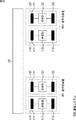
例えば、送信装置210の信号源213−1による電圧の実効値Vtrmsを2[V]に固定し、信号源213−1が生成する信号の周波数fを1[MHz]、10[MHz]、または100[MHz]とし、Rr223−1の抵抗値を10[KΩ]、100[KΩ]、または1[MΩ]とし、回路全体の静電容量Cxを0.1[pF]、1[pF]、または10[pF]としたときの、Rr223−1の両端に生じる電圧の実効値Vrrmsの計算結果は図3に示される表250のようになる。 For example, the effective value V trms of the voltage by the signal source 213-1 of the transmission device 210 is fixed to 2 [V], and the frequency f of the signal generated by the signal source 213-1 is 1 [MHz], 10 [MHz], Or 100 [MHz], the resistance value of Rr 223-1 is 10 [KΩ], 100 [KΩ], or 1 [MΩ], and the capacitance C x of the entire circuit is 0.1 [pF], 1 [pF ] Or 10 [pF], the calculation result of the effective value V rrms of the voltage generated at both ends of Rr 223-1 is as shown in Table 250 shown in FIG.
表250に示されるように、電圧の実効値Vrrmsの計算結果は、その他の条件が同じ場合、周波数fが1[MHz]のときよりも10[MHz]のときの方が大きくなり、受信負荷であるRr223−1の抵抗値が10[KΩ]のときよりも1[MΩ]の時のほうが大きくなり、静電容量Cxが0.1[pF]のときよりも10[pF]の時のほうが大きな値をとる。すなわち、周波数fの値、Rr223−1の抵抗値、および静電容量Cxが大きいほど、大きな電圧の実効値Vrrmsが得られる。 As shown in Table 250, when the other conditions are the same, the calculation result of the voltage effective value V rrms is larger when the frequency f is 10 [MHz] than when the frequency f is 1 [MHz]. The resistance value of the load Rr 223-1 is larger when the resistance value is 1 [MΩ] than when the resistance value is 10 [KΩ], and is 10 [pF] than when the capacitance C x is 0.1 [pF]. Time takes a larger value. That is, the value of the frequency f, the resistance value of the Rr 223-1, and the larger the capacitance C x, the effective value V RRMS large voltage can be obtained.
また、表250より、ピコファラド以下の静電容量でも、Rr223−1には電気信号が発生することが分かる。すなわち、伝送される信号の信号レベルが微小な場合、受信装置220の検出器223−2によって検出した信号を増幅する等すれば、通信が可能となる。 Further, it can be seen from Table 250 that an electrical signal is generated in Rr 223-1 even with a capacitance of picofarad or less. That is, when the signal level of the transmitted signal is very small, communication can be performed by amplifying the signal detected by the detector 223-2 of the receiving device 220.
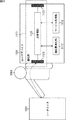
次に、以上に示した等価回路の通信システム200の各パラメータの算出例を、図4を参照して具体的に説明する。図4は、通信システム100の物理的な構成による影響も含めて演算例を説明するための図である。 Next, a calculation example of each parameter of the communication system 200 having the equivalent circuit described above will be specifically described with reference to FIG. FIG. 4 is a diagram for explaining a calculation example including the influence of the physical configuration of the communication system 100.
図4に示される通信システム300は、図1の通信システム100に対応するシステムであり、図2の通信システム200に通信システム100の物理的な構成に関する情報を付加したものである。つまり、通信システム300は、送信装置310、受信装置320、および通信媒体330を有している。図1の通信システム100と対比して説明すると、送信装置310は送信装置110に対応し、受信装置320は受信装置120に対応し、通信媒体330は、通信媒体130に対応する。
A communication system 300 shown in FIG. 4 is a system corresponding to the communication system 100 of FIG. 1, and is obtained by adding information related to the physical configuration of the communication system 100 to the communication system 200 of FIG. That is, the communication system 300 includes a transmission device 310, a reception device 320, and a communication medium 330. In comparison with the communication system 100 in FIG. 1, the transmission device 310 corresponds to the
送信装置310は、送信信号電極111に対応する送信信号電極311、送信基準電極112に対応する送信基準電極312、および送信部113に対応する信号源313−1を有している。つまり、信号源313−1の両側の端子の一方に送信信号電極311が接続され、他方に送信基準電極312が接続されている。送信信号電極311は、通信媒体330に近接するように設けられている。送信基準電極312は、通信媒体330に影響されない程度に通信媒体330から離されて設けられており、送信装置310の外部の空間に対して静電容量を有するように構成されている。なお、図2においては、送信部113には、信号源213−1および送信装置内基準点213−2が対応するように説明したが、図4の場合、説明の便宜上、この送信装置内基準点は省略している。
The transmission device 310 includes a transmission signal electrode 311 corresponding to the
受信装置320も、送信装置310の場合と同様に、受信信号電極121に対応する受信信号電極321、受信基準電極122に対応する受信基準電極322、および受信部123に対応するRr323−1および検出器323−2を有している。つまり、Rr323−1の両側の端子の一方に受信信号電極321が接続され、他方に受信基準電極322が接続されている。受信信号電極321は、通信媒体330に近接するように設けられている。受信基準電極322は、通信媒体330に影響されない程度に通信媒体330から離されて設けられており、受信装置320の外部の空間に対して静電容量を有するように構成されている。なお、図2において受信部123には、Rr223−1、検出器223−2、および受信装置内基準点223−3が対応するように説明したが、図4の場合、説明の便宜上、この受信装置内基準点は省略している。
Similarly to the case of the transmission device 310, the reception device 320 also includes the reception signal electrode 321 corresponding to the
なお、通信媒体330は、図1や図2の場合と同様に完全導体であるものとする。送信装置310と受信装置320は、互いに十分な距離をおいて配置されており、相互の影響は無視できるものとする。また、送信信号電極311は通信媒体330とのみ静電結合している。また、送信基準電極312は送信信号電極311に対して十分な距離をおいて配置されており、相互の影響は無視できるものとする。同様に、受信信号電極321は通信媒体330とのみ静電結合している。また、受信基準電極322は受信信号電極321に対して十分な距離をおいて配置されており、相互の影響は無視できるものとする。なお厳密には、送信信号電極311、受信信号電極321、および通信媒体330は、空間に対する静電容量を有するが、ここでは、説明の便宜上、これらについて無視できるものとする。
It is assumed that the communication medium 330 is a complete conductor as in the case of FIGS. The transmitting device 310 and the receiving device 320 are arranged at a sufficient distance from each other, and the mutual influence can be ignored. The transmission signal electrode 311 is electrostatically coupled only to the communication medium 330. Further, the
図4に示されるように、通信システム300において、通信媒体330の一方の端に送信装置310が配置され、もう一方の端に受信装置320が配置されている。 As shown in FIG. 4, in the communication system 300, the transmission device 310 is disposed at one end of the communication medium 330 and the reception device 320 is disposed at the other end.
送信信号電極311と通信媒体330の間には距離dte[m]の間隔があるものとする。また、送信信号電極311が、片面の表面積がSte[m2]である導体円板とすると、通信媒体330との間で形成される静電容量Cte314は次の式(9)のように求めることが出来る。
It is assumed that there is a distance dte [m] between the transmission signal electrode 311 and the communication medium 330. Further, when the transmission signal electrode 311 is a conductor disk having a surface area of Ste [m 2 ] on one side, a
![]()
![]()
式(9)は、一般に平行平板の静電容量として知られている算出式である。上式で、εは誘電率を示すが、いま、通信システム300は空気中に置かれているものとすると、比誘電率εrはほぼ1とみなせるので、誘電率εは、真空における誘電率ε0と等価とみなすことができる。送信信号電極311の表面積Steを2×10⁻³[m2](直径約5[cm])とし、間隔dteを5×10⁻³[m](5[mm])として、静電容量Cte314を求めると、以下の式(10)のようになる。 Formula (9) is a calculation formula generally known as the capacitance of a parallel plate. In the above equation, ε represents a dielectric constant. Now, assuming that the communication system 300 is placed in the air, the relative dielectric constant ε r can be regarded as approximately 1. Therefore, the dielectric constant ε is a dielectric constant in a vacuum. It can be regarded as equivalent to ε 0 . The transmission signal electrode 311 has a surface area Ste of 2 × 10 −3 [m 2 ] (diameter of about 5 [cm]) and an interval dte of 5 × 10 −3 [m] (5 [mm]). Is obtained as shown in the following equation (10).
なお、実際の物理現象として上述した式(9)が厳密に成立するのは、Ste>>dteの関係を満足している場合であるが、ここでは、式(9)で近似できるものとする。 Note that the above equation (9) is strictly established as an actual physical phenomenon when the relationship of Ste >> dte is satisfied, but here it can be approximated by the equation (9). .
次に、送信基準電極312と空間から成る静電容量(送信基準電極312と、送信基準電極312からの仮想的な無限遠点を示す基準点316との間の静電容量)Ctg315について説明する。一般に、半径r[m]の円板が空間に置かれていた場合、その円板と空間との間に形成される静電容量C[F]は次の式(11)で求めることができる。
Next, the
![]()
![]()
送信基準電極312が半径rtg=2.5×10⁻²[m](半径2.5[cm])の導体円板であるとすると、送信基準電極317と空間から成る静電容量Ctg315は、上述した式(11)を用いて、次の式(12)のように求められる。なお、通信システム300は空気中に置かれ、その空間の誘電率は真空の誘電率ε0で近似できるものとする。
If the
受信信号電極321の大きさを送信信号電極311と同じ(Sre[m2]=Ste[m2]の導体円板)とし、通信媒体330との間隔も同じ(dre[m]=dte[m])とすれば、受信信号電極321と通信媒体330から成る静電容量Cre324は、送信側と同じく3.5[pF]となる。また、受信基準電極322の大きさを送信基準電極312と同じ(半径rrg[m]=rtg[m]の導体円板)とすれば、受信基準電極322と空間から成る静電容量(受信基準電極322と、受信基準電極322からの仮想的な無限遠点を示す基準点326との間の静電容量)Crg325は、送信側と同じく1.8[pF]となる。以上から、Cte314、Ctg315、Cre324、およびCrg325の四つの静電容量から成る合成静電容量Cxは上述した式(4)を用いて次の式(13)のように求めることができる。
The size of the reception signal electrode 321 is the same as that of the transmission signal electrode 311 (conductor disk of Sre [m 2 ] = Ste [m 2 ]), and the distance from the communication medium 330 is also the same (dre [m] = dte [m ]), The
信号源313−1の周波数fを1[MHz]とし、電圧の実効値Vtrmsを2[V]とし、Rr323−1を100K[Ω]とすると、Rr323−1の両端に生じる電圧Vrrmsは、以下の式(14)のように求めることができる。 When the frequency f of the signal source 313-1 is 1 [MHz], the effective value V trms of the voltage is 2 [V], and Rr323-1 is 100 K [Ω], the voltage V rrms generated at both ends of the Rr323-1 is The following equation (14) can be obtained.
以上の結果から、基本原理として、空間と成す静電容量を利用することによって、送信装置から受信装置への信号の受け渡しが可能である。 From the above results, as a basic principle, it is possible to transfer a signal from the transmission device to the reception device by using the capacitance formed with the space.
以上において説明した送信基準電極や受信基準電極の空間に対する静電容量は、各電極の位置に空間が存在すれば形成可能である。従って、上述した送信装置および受信装置は、通信媒体によって送信信号電極と受信信号電極が結合されていれば、互いの距離に依存せずに通信の安定性を得ることができる。 The capacitance with respect to the space of the transmission reference electrode and the reception reference electrode described above can be formed if there is a space at the position of each electrode. Therefore, if the transmission signal electrode and the reception signal electrode described above are coupled by a communication medium, the transmission device and the reception device described above can obtain communication stability without depending on the distance between each other.
次に、実際に本通信システムを物理的に構成する場合について説明する。図5は、以上において説明した通信システムの、実際に物理的に構成する場合における、システム上に発生する各パラメータの演算用モデルの例を示す図である。 Next, the case where this communication system is actually configured will be described. FIG. 5 is a diagram illustrating an example of a calculation model for each parameter generated on the system when the communication system described above is actually physically configured.
つまり、通信システム400は、送信装置410、受信装置420、および通信媒体430を有しており、上述した通信システム100(通信システム200および通信システム300)に対応するシステムであり、評価するパラメータが異なるだけで、その構成は、通信システム100乃至通信システム300と基本的に同様である。
That is, the communication system 400 includes the
つまり、通信システム300と対比して説明すると、送信装置410は送信装置310に対応し、送信装置410の送信信号電極411は送信信号電極311に対応し、送信基準電極412は送信基準電極312に対応し、信号源431−1は信号源331−1に対応する。また、受信装置420は受信装置320に対応し、受信装置420の受信信号電極421は受信信号電極321に対応し、受信基準電極422は受信基準電極322に対応し、Rr423−1はRr323−1に対応し、検出器423−2は検出器323−2に対応する。さらに、通信媒体430は通信媒体330に対応する。
That is, in comparison with the communication system 300, the
また、パラメータについて説明すると、送信信号電極411と通信媒体430との間の静電容量Cte414は通信システム300のCte314に対応し、送信基準電極412の空間に対する静電容量Ctg415は通信システム300のCtg315に対応し、送信装置410からの空間上の仮想的な無限遠点を示す基準点416−1および基準点416−2は通信システム300の基準点316に対応する。また、送信信号電極411は、面積Ste[m2]の円板状の電極であり、通信媒体430から微小距離dte[m]だけ離れた位置に設けられる。送信基準電極412も円板状の電極であり、その半径は、rtg[m]である。
The
受信装置420側では、受信信号電極421と通信媒体430との間の静電容量Cre424は通信システム300のCre324に対応し、受信基準電極422の空間に対する静電容量Crg425は通信システム300のCrg325に対応し、受信装置420からの空間上の仮想的な無限遠点を示す基準点426−1および基準点426−2は通信システム300の基準点326に対応する。また、受信信号電極421は、面積Sre[m2]の円板状の電極であり、通信媒体430から微小距離dre[m]だけ離れた位置に設けられる。受信基準電極422も円板状の電極であり、その半径は、rrg[m]である。
On the receiving device 420 side, the
図5の通信システム400は、以上のパラメータに加えて、以下のような新たなパラメータが追加されたモデルである。 The communication system 400 of FIG. 5 is a model in which the following new parameters are added to the above parameters.
例えば、送信装置410については、送信信号電極411と送信基準電極412との間に形成される静電容量Ctb417−1、送信信号電極411と空間との間に形成される静電容量Cth417−2、および、送信基準電極412と通信媒体430との間に形成される静電容量Cti417−3が新たなパラメータとして追加されている。
For example, with respect to the
また、受信装置420については、受信信号電極421と受信基準電極422との間に形成される静電容量Crb427−1、受信信号電極421と空間との間に形成される静電容量Crh427−2、および、受信基準電極422と通信媒体430との間に形成される静電容量Cri427−3が新たなパラメータとして追加されている。
As for the receiving device 420, an electrostatic capacitance Crb 427-1 formed between the reception signal electrode 421 and the
さらに、通信媒体430については、通信媒体430と空間との間に形成される静電容量(通信媒体430と、通信媒体430からの仮想的な無限遠点を示す基準点436との間の静電容量)Cm432が新たなパラメータとして追加されている。また、実際には、通信媒体430は、その大きさや材質等によって電気抵抗を有するので、その抵抗成分として抵抗値Rm431およびRm433が新たなパラメータとして追加されている。
Further, with respect to the
なお、図5の通信システム400においては省略されているが、通信媒体が導電性だけでなく、誘電性を有する場合には、その誘電率に従った静電容量も併せて形成される。また、通信媒体に導電性がなく、誘電性のみで形成される場合には、送信信号電極411と受信信号電極421の間に、誘電体の誘電率、距離、大きさ、配置で決まる静電容量で結合されることになる。
Although omitted in the communication system 400 of FIG. 5, when the communication medium has not only conductivity but also dielectric properties, a capacitance according to the dielectric constant is also formed. In addition, when the communication medium is not conductive and is formed only of dielectric, an electrostatic capacitance determined by the dielectric constant, distance, size, and arrangement of the dielectric between the
また、ここでは、送信装置410と受信装置420が、互いに静電結合的な要素が無視できる程度に距離が離れている場合(送信装置410と受信装置420との間の静電結合の影響を無視することができる場合)を想定している。仮に、距離が近い場合には、上述した考え方に従い、送信装置410内の各電極と受信装置420内の各電極の位置関係によっては、それら電極同士の静電容量も考慮する必要が生じることもある。
In addition, here, when the
次に、図5の通信システム400の動作を、電気力線を用いて説明する。通信システム400の送信装置410の、電極同士、または電極と通信媒体430との関係を、電気力線を用いて表現した模式図を図6および図7に示す。
Next, the operation of the communication system 400 of FIG. 5 will be described using electric lines of force. FIG. 6 and FIG. 7 are schematic diagrams expressing the relationship between the electrodes of the
図6は、通信システム400の送信装置410について、通信媒体430が存在しない場合の電気力線の分布の例を示す模式図である。いま、送信信号電極411は正の電荷を有し(正に帯電し)、送信基準電極412は負の電荷を有している(負に帯電している)ものとする。図中の矢印は電気力線を示し、その方向は、正の電荷から負の電荷へ向いている。電気力線は、途中で突然消滅することはなく、異符号の電荷を持つ物体に到達するか、仮想無限遠点に到達するかのいずれかの性質を持つ。
FIG. 6 is a schematic diagram illustrating an example of the distribution of lines of electric force when the
ここで、電気力線451は、送信信号電極411から放出された電気力線のうち無限遠点に到達しているものを示す。電気力線452は、送信基準電極412に向かっている電気力線のうち仮想無限遠点より到達しているものを示す。電気力線453は、送信信号電極411と送信基準電極412との間で生じている電気力線を示す。これらの電気力線の分布は、各電極の大きさや位置関係によって影響を受ける。
Here, the electric lines of
図7は、このような送信装置410に通信媒体430を近づけた場合の電気力線の分布の例を示す模式図である。送信信号電極411に通信媒体430が近づいたため、両者間の結合が強まり、図6で無限遠点に到達していた電気力線451の多くが、通信媒体430に到達する電気力線461となり、無限遠点への電気力線463(図6における電気力線451)は減少する。これに伴って、通信信号電極411からみたときの無限遠点に対する静電容量(図5のCth417−2)は弱まり、通信媒体430との間の静電容量(図5のCte414)が増す。なお、実際には、送信基準電極412と、通信媒体430間の静電結合(図5のCti417−3)も存在するが、ここでは無視出来るものとする。
FIG. 7 is a schematic diagram illustrating an example of the distribution of lines of electric force when the
ガウスの法則によれば、任意の閉曲面Sを通って出て行く電気力線の数N[本]は、その閉曲面S内に含まれる全電荷を誘電率εで割ったものに等しく、閉曲面Sの外にある電荷には影響を受けない。いま閉曲面Sにn個の電荷が存在するとき、次式が成立する。 According to Gauss's law, the number N of lines of electric force exiting through any closed surface S is equal to the total charge contained in the closed surface S divided by the dielectric constant ε. The charge outside the closed curved surface S is not affected. When n charges are present on the closed curved surface S, the following equation is established.
ここで、iは整数とする。変数qiは個々の電荷の電荷量を示す。この法則は、閉曲面Sから湧き出す電気力線は、この閉曲面S内に存在する電荷から発せられる電気力線のみで決まり、外側から入ってくる電気力線の全ては、別の場所から出て行くことを示している。 Here, i is an integer. The variable q i indicates the charge amount of each charge. According to this law, the electric lines of force that spring out from the closed curved surface S are determined only by the electric lines of force generated from the charges existing in the closed curved surface S, and all the electric lines of force that enter from the outside are from different locations. Indicates going out.
この法則に従えば、図7において、通信媒体430が接地されていないものとすると、この通信媒体430近傍の閉曲面471には電荷の発生源は存在しないから、電気力線461近傍の通信媒体の領域472では、静電誘導により電荷Q3が誘起される。通信媒体430は接地されていないため、通信媒体430が持つ総電荷量は変わらないから、電荷Q3が誘起された領域472の外の領域473では、電荷Q3と等量で異符号の電荷Q4が誘起され、これによって生じる電気力線464が閉曲面471から出て行くことになる。電荷Q4は通信媒体が大きい程、より拡散することになり、電荷密度も減少するから、これに伴って単位面積当たりの電気力線の本数も減少する。
According to this law, if the
通信媒体430が完全導体である場合、完全導体の性質から、部位によらず電位が同一になる特性上、部位によらず電荷密度もほぼ等しくなる性質がある。通信媒体430が抵抗分を持った導電体である場合には、その抵抗分に応じ、距離に応じて電気力線の数も減少する。また通信媒体430が導電性を持たない誘電体である場合には、その分極作用により、電気力線は拡散され、伝播される。いま空間にn個の導電体が存在しているとき、各導電体の電荷Qiは、次式で求めることが出来る。
In the case where the
ここで、i、jは整数であり、Cijは導電体iと導電体jから成る容量係数を示し、静電容量と同じ性質と考えてよい。容量係数は、導電体の形状とそれらの位置関係からのみ決まる。容量係数Ciiは、導電体i自身が空間に対して形成する静電容量となる。また、Cij=Cjiである。式(16)においては、複数の導電体から成る系が重ねの理に基づいて動作することが示されており、導電体間の静電容量と各導電体の電位との積の総和によって該当する導電体の電荷が定まることが示されている。 Here, i and j are integers, and C ij represents a capacitance coefficient composed of the conductor i and the conductor j, and may be considered to have the same property as the capacitance. The capacitance coefficient is determined only from the shapes of the conductors and their positional relationship. The capacitance coefficient C ii is a capacitance that the conductor i itself forms with respect to the space. Also, C ij = C ji . In equation (16), it is shown that a system composed of a plurality of conductors operates based on the principle of superposition, and corresponds to the sum of products of the capacitance between conductors and the potential of each conductor. It is shown that the electric charge of the conductor is determined.
いま、図7と式(16)において互いに関連する各パラメータを以下のように定める。例えば、Q1は、送信信号電極411に誘起される電荷を示し、Q2は、送信基準電極412に誘起される電荷を示し、Q3は、送信信号電極411によって通信媒体430に誘起される電荷を示し、Q4は、通信媒体430上の、電荷Q3と異符号等量の電荷を示しているものとする。
Now, parameters related to each other in FIG. 7 and Expression (16) are determined as follows. For example, Q1 represents the charge induced in the
また、V1が送信信号電極411の、無限遠点を基準としたときの電位を示し、V2が送信基準電極412の、無限遠点を基準としたときの電位を示し、V3が通信媒体430の、無限遠点を基準としたときの電位を示し、C12が送信信号電極411と送信基準電極412間の容量係数を示し、C13が送信信号電極411と通信媒体430間の容量係数を示し、C15が送信信号電極411と空間の容量係数を示し、C25が送信信号電極411と空間の容量係数を示し、さらにC45が通信媒体430と空間の容量係数を示しているものとする。
In addition, V1 represents the potential of the
このとき電荷Q3は次式のように求めることができる。 At this time, the charge Q3 can be obtained as follows.
![]()
![]()
通信媒体430により多くの電界を注入するためには、電荷Q3を大きくすればよいが、そのためには、送信信号電極411と通信媒体430間の容量係数C13を高め、且つ、十分な電位V1を与えればよい。容量係数C13は、形状と位置関係のみで決まるが、相互間の距離が近く、対向面積が大きい程、静電容量が高まる。次に、電位V1であるが、この電位は無限遠点からみたとき十分な電位が生じている必要がある。送信装置410からみると信号源によって、送信信号電極411と送信基準電極412の間に電位差が与えられているが、この電位差が無限遠点からみたときにも十分な電位差として生じるためには、送信基準電極412の振る舞いが重要になる。
In order to inject more electric field into the
仮に送信基準電極412が微小で、送信信号電極411が十分な大きさであるとすると、容量係数C12及びC25が小さくなる。一方で、容量係数C13、C15、C45は大きな静電容量を持つから、電気的により変動しにくくなり、信号源で発生させている電位差のほとんどは、送信基準電極412の電位V2として現れ、送信信号電極411の電位V1は小さくなってしまう。
If the
この様子を図8に示す。送信基準電極481は微小なため、どの導電体や無限遠点とも結合しない。送信信号電極411は、通信媒体430との間で静電容量Cteを形成するとともに、空間に対して静電容量Cth417−2を形成する。また、通信媒体430は空間に対して静電容量Cm432を形成する。送信信号電極411と送信基準電極412に電位が生じても、送信信号電極411に関わる静電容量Cte414、Cth417−2、およびCm432が圧倒的に大きいため、この電位を変動させるためには、大きなエネルギーが必要となるが、信号源413−1の対向側の送信基準電極481の静電容量が弱いため、送信信号電極411の電位はほとんど変化せず、信号源413−1の電位変動のほとんどは、送信基準電極481側に現れることになる。
This is shown in FIG. Since the transmission reference electrode 481 is minute, it does not couple with any conductor or infinity point. The
逆に、送信信号電極411が微小で、送信基準電極481が十分な大きさであるとすると、送信基準電極481の静電容量が高まって、電気的に変動しにくくなり、送信信号電極411に十分な電位V1は生じるが、通信媒体430との静電結合が弱まるため、十分な電界を注入できない。
On the other hand, if the
従って、全体のバランスの中で、通信に必要な電界を送信信号電極から通信媒体に注入しながらも、十分な電位を与えることが出来るだけの送信基準電極を設ける必要がある。ここでは、送信側のみを考えたが、図5における受信装置420の電極と通信媒体430の間に関しても同様に考えることが出来る。
Therefore, it is necessary to provide a transmission reference electrode that can provide a sufficient potential while injecting an electric field necessary for communication from the transmission signal electrode into the communication medium in the overall balance. Here, only the transmission side is considered, but the same can be considered between the electrode of the reception device 420 and the
無限遠点は、物理的に遠距離でなければならないものではなく、実用上は装置周辺の空間を考えればよいが、より理想としては、システム全体の系の中で、より安定して電位変動が少ないことが望ましい。実際の利用環境下では、AC電源ラインや照明器具、その他電気機器等から発生するノイズが存在するが、少なくとも信号源が利用する周波数帯域にこれらのノイズが重ならないか、無視出来るレベルであればよい。 The infinity point does not have to be physically far away, and in practice it is only necessary to consider the space around the device, but more ideally, the potential fluctuation is more stable in the system as a whole. It is desirable that there is little. Under actual usage conditions, there are noises generated from AC power lines, lighting equipment, and other electrical equipment, but these noises do not overlap at least in the frequency band used by the signal source or can be ignored. Good.
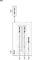
図9は、図5に示されるモデル(通信システム400)を等価回路で示した図である。つまり、図2と図4の関係のように、図9に示される通信システム500は図5に示される通信システム400に対応し、通信システム500の送信装置510は通信システム400の送信装置410に対応し、通信システム500の受信装置520は通信システム400の受信装置420に対応し、通信システム500の接続線530は通信システム400の通信媒体430に対応する。
FIG. 9 is a diagram showing an equivalent circuit of the model (communication system 400) shown in FIG. That is, as in the relationship between FIGS. 2 and 4, the communication system 500 illustrated in FIG. 9 corresponds to the communication system 400 illustrated in FIG. 5, and the transmission device 510 of the communication system 500 is connected to the
同様に、図9の送信装置510において、信号源513−1は信号源413−1に対応する。なお、図9の送信装置510においては、図5において省略された、図2の送信装置内基準点213−2に対応する、図1の送信部113内部の回路におけるグランドを示す送信装置内基準点513−2が示されている。
Similarly, in the transmission apparatus 510 of FIG. 9, the signal source 513-1 corresponds to the signal source 413-1. In the transmission apparatus 510 of FIG. 9, the transmission apparatus internal reference indicating the ground in the circuit inside the
また、図9のCte514は、図5のCte414に対応する静電容量であり、Ctg515は、図5のCtg415に対応する静電容量であり、基準点516−1および基準点516−2は、それぞれ、基準点416−1および基準点416−2に対応する。さらにCtb517−1はCtb417−1に、Cth517−2はCth417−2に、Cti517−3はCti417−3にそれぞれ対応する静電容量である。
Further,
受信装置520の各部も同様であり、受信抵抗であるRr523−1および検出器523−2は、それぞれ、図5のRr423−1および検出器423−2に対応する。なお、図9の受信装置520においては、図5において省略された、図2の受信装置内基準点223−3に対応する、図1の受信部123内部の回路におけるグランドを示す受信装置内基準点523−3が示されている。
The same applies to each part of the receiving device 520, and Rr 523-1 and detector 523-2, which are reception resistors, correspond to Rr 423-1 and detector 423-2 in FIG. 5, respectively. In the receiving apparatus 520 in FIG. 9, the reference in the receiving apparatus that indicates the ground in the circuit in the receiving
また、図9のCre524は、図5のCre424に対応する静電容量であり、Crg525は、図5のCrg425に対応する静電容量であり、基準点526−1および基準点526−2は、それぞれ、基準点426−1および基準点426−2に対応する。さらにCrb527−1はCrb427−1に、Crh527−2はCrh427−2に、Cri527−3はCri427−3にそれぞれ対応する静電容量である。
In addition,
接続線530に接続される各部も同様であり、接続線の抵抗成分であるRm531とRm533は、それぞれ、Rm431とRm433に対応し、Cm532はCm432に対応し、基準点536は、基準点436に対応する。
The same applies to each part connected to the
このような通信システム500は、以下のような性質を有する。 Such a communication system 500 has the following properties.
例えば、送信装置510は、Cte514の値が大きい(容量が高い)程、通信媒体430に対応する接続線530へ大きな信号を印加することができる。また、送信装置510は、Ctg515の値が大きい(容量が高い)程、接続線530へ大きな信号を印加することができる。さらに、送信装置510は、Ctb517−1の値が小さい(容量が低い)程、接続線530へ大きな信号を印加することが出来る。また、送信装置510は、Cth517−2の値が小さい(容量が低い)程、接続線530へ大きな信号を印加することが出来る。さらに、送信装置510は、Cti517−3の値が小さい(容量が低い)程、接続線530へ大きな信号を印加することが出来る。
For example, the transmission device 510 can apply a larger signal to the
受信装置520は、Cre524の値が大きい(容量が高い)程、通信媒体430に対応する接続線530から大きな信号を取り出すことが出来る。また、受信装置520は、Crg525の値が大きい(容量が高い)程、接続線530から大きな信号を取り出すことが出来る。さらに、受信装置520は、Crb527−1の値が小さい(容量が低い)程、接続線530から大きな信号を取り出すことが出来る。また、受信装置520は、Crh527−2の値が小さい(容量が低い)程、接続線530から大きな信号を取り出すことが出来る。さらに、受信装置520は、Cri527−3の値が小さい(容量が低い)程、接続線530から大きな信号を取り出すことが出来る。また、受信装置520は、Rr523−1の値が低い(抵抗が高い)程、接続線530から大きな信号を取り出すことが出来る。
The reception device 520 can extract a larger signal from the
接続線530の抵抗成分であるRm531およびRm533の値が低い(抵抗が低い)程、送信装置510は、接続線530へ大きな信号を印加することが出来る。また、接続線530の空間に対する静電容量であるCm532の値が小さい(容量が低い)程、送信装置510は、接続線530へ大きな信号を印加することが出来る。
The transmission device 510 can apply a larger signal to the
コンデンサ容量の大小は、電極の表面積の大きさに略比例するから、一般には各電極の大きさが大きい程よいが、単純に電極の大きさを大きくすると、電極同士の間の静電容量も増加してしまう恐れもある。また、電極の大きさ比が極端な場合も効率が低下する恐れがある。従って、電極の大きさやその配置場所等は、全体のバランスの中で決定する必要がある。 Since the size of the capacitor is roughly proportional to the surface area of the electrode, it is generally better to increase the size of each electrode. However, simply increasing the size of the electrode also increases the capacitance between the electrodes. There is also a risk of it. In addition, the efficiency may decrease even when the size ratio of the electrodes is extreme. Therefore, it is necessary to determine the size of the electrode and the location of the electrode within the overall balance.
なお、上述した通信装置500の性質は、信号源513−1の周波数が高い周波数帯域では、インピーダンス・マッチングの考え方で本等価回路を捉え、各パラメータを決定することで効率的な通信が可能となる。周波数を高めることにより、小さい静電容量でもリアクタンスが確保できるため、各装置を容易に小型化することができる。 Note that the property of the communication device 500 described above is that, in the frequency band where the frequency of the signal source 513-1 is high, efficient communication is possible by capturing the equivalent circuit based on the concept of impedance matching and determining each parameter. Become. By increasing the frequency, reactance can be ensured even with a small capacitance, so that each device can be easily downsized.
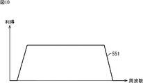
また、一般的にコンデンサのリアクタンスは周波数の減少とともに上昇する。これに対して、通信システム500は静電容量結合に基づく動作をするので、信号源513−1が生成する信号の周波数の下限は、これによって決定される。また、Rm531、Cm532、およびRm533は、その配置から低域通過フィルタを形成することになるので、この特性により周波数の上限が定まる。 In general, the reactance of a capacitor increases as the frequency decreases. On the other hand, since the communication system 500 operates based on capacitive coupling, the lower limit of the frequency of the signal generated by the signal source 513-1 is determined thereby. Since Rm531, Cm532, and Rm533 form a low-pass filter based on the arrangement, the upper limit of the frequency is determined by this characteristic.
つまり、通信システム500の周波数特性は、図10に示されるグラフの曲線551のようになる。図10において、横軸は周波数を、縦軸は系全体の利得を示している。
That is, the frequency characteristic of the communication system 500 is as shown by a
次に、図5の通信システム400、および図9の通信システム500の各パラメータの具体的な数値を検討する。なお、以下において、説明の便宜上、通信システム400(通信システム500)は空気中に設置されているものとする。また、通信システム400の送信信号電極411、送信基準電極412、受信信号電極421、および受信基準電極422(通信システム500の送信信号電極511、送信基準電極512、受信信号電極521、および受信基準電極522)は、いずれも、直径5cmの導体円板とする。
Next, specific numerical values of the parameters of the communication system 400 in FIG. 5 and the communication system 500 in FIG. 9 will be considered. In the following, for convenience of explanation, it is assumed that the communication system 400 (communication system 500) is installed in the air. Further, the
図5の通信システム400において、送信信号電極411と通信媒体430からなる静電容量Cte414(図9のCte514)は、互いの間隔dteが5mmとすると、その値は、上述した式(9)を用いて、以下の式(18)ように求められる。
In the communication system 400 of FIG. 5, the capacitance Cte 414 (
電極間の静電容量であるCtb417−1(図9のCtb517−1)については、式(9)を適応することができるものとする。本来は上述したように電極の面積が間隔に比べて十分に大きい場合に成立する式であるが、ここでは、これで近似できるとして差し支えない。電極間の間隔を5cmとすると、Ctb417−1(図9のCtb517−1)は以下の式(19)ようになる。 For Ctb 417-1 (Ctb 517-1 in FIG. 9), which is the capacitance between the electrodes, equation (9) can be applied. Originally, as described above, the equation is established when the area of the electrode is sufficiently larger than the interval, but here it may be approximated. When the distance between the electrodes is 5 cm, Ctb 417-1 (Ctb 517-1 in FIG. 9) is expressed by the following equation (19).
ここでの想定は、送信信号電極411と通信媒体430の間隔が狭いとすれば、空間との結合は弱くなるので、Cth417−2(図9のCht517−2)の値は、Cte414(Cte514)の値よりも十分小さく、式(20)のようにCte414(Cte514)の値の十分の一に設定されるものとする。
The assumption here is that if the distance between the
![]()
![]()
送信基準電極412と空間で形成される静電容量を示すCtg415(図9のCtg515)は図4の場合(式(12))と同様であり、次式(21)のように求めることができる。
Ctg 415 (
![]()
![]()
Cti417−3(図9のCti517−3)の値は、以下のように、Ctb417−1(図9のCtb517−1)と同等と考える。 The value of Cti417-3 (Cti517-3 in FIG. 9) is considered to be equivalent to Ctb417-1 (Ctb517-1 in FIG. 9) as follows.
Cti=Ctb=0.35[pF] Cti = Ctb = 0.35 [pF]
受信装置420(図9の受信装置520)の各パラメータに関しても、各電極の構成(大きさや設置位置等)を送信装置410の場合と同様にすれば、以下のように、送信装置410の各パラメータと同様に設定される。
Regarding each parameter of the receiving device 420 (receiving device 520 in FIG. 9), if the configuration (size, installation position, etc.) of each electrode is the same as that of the transmitting
Cre=Cte=3.5[pF] Crb=Ctb=0.35[pF] Crh=Cth=0.35[pF] Crg=Ctg=1.8[pF] Cri=Cti=0.35[pF] Cre = Cte = 3.5 [pF] Crb = Ctb = 0.35 [pF] Crh = Cth = 0.35 [pF] Crg = Ctg = 1.8 [pF] Cri = Cti = 0.35 [pF]
また、説明の便宜上、以下において、通信媒体430(図9の接続線530)は人体のサイズ程度の生体に近い特性を有する物体であるとする。そして、通信媒体430の送信信号電極411の位置から受信信号電極421の位置(図9の送信信号電極511の位置から受信信号電極521の位置)までの電気抵抗が1[MΩ]であるとし、Rm431およびRm433(図9のRm531およびRm533)の値をそれぞれ500[KΩ]とする。また、通信媒体430と空間との間で形成する静電容量Cm432(図9のCm532)の値を100[pF]とする。
For convenience of explanation, it is assumed below that the communication medium 430 (
さらに、信号源413−1(図9の信号源513−1)は、最大値1[V]で周波数が10[MHz]の正弦波とする。 Further, the signal source 413-1 (the signal source 513-1 in FIG. 9) is a sine wave having a maximum value of 1 [V] and a frequency of 10 [MHz].
以上のパラメータを使ってシミュレーションを行うと、図11に示されるような波形の受信信号がシミュレーション結果として得られる。図11に示されるグラフは、縦軸が、受信装置420(図9の受信装置520)の受信負荷であるRr423−1(Rr523−1)の両端電圧を表し、横軸が時間を表している。図11の両矢印552により示されるように、受信信号の波形の最大値Aと最小値Bとの差(ピーク値の差)が約10[μV]程度で観測される。従って、これを十分なゲインを持つ増幅器(検出器423−2)で増幅することによって、送信側の信号(信号源413−1において生成された信号)を受信側で復元することができる。
When simulation is performed using the above parameters, a reception signal having a waveform as shown in FIG. 11 is obtained as a simulation result. In the graph shown in FIG. 11, the vertical axis represents the voltage across Rr 423-1 (Rr 523-1), which is the reception load of the receiving device 420 (the receiving device 520 in FIG. 9), and the horizontal axis represents time. . As indicated by a double-headed
このように、以上において説明した、本発明を適用した通信システムは、物理的な基準点経路を不要とし、通信信号伝達経路のみによる通信を実現することができるので、利用環境の制約を受けない通信環境を容易に提供することができる。 As described above, the communication system to which the present invention is applied as described above does not require a physical reference point path and can realize communication using only the communication signal transmission path, and thus is not restricted by the use environment. A communication environment can be easily provided.
次に、各装置における各電極の配置について説明する。上述したように、各電極は、互いに異なる役目を担っており、通信媒体や空間等に対して静電容量を形成する。つまり、各電極はそれぞれ互いに異なる相手と静電結合し、その静電結合を用いて作用する。従って、各電極の配置方法は、そのように各電極を目的の対象物に有効に静電結合させるために非常に重要な要因となる。 Next, the arrangement of each electrode in each device will be described. As described above, each electrode has a different role and forms a capacitance with respect to a communication medium, space, or the like. In other words, each electrode is electrostatically coupled to a different partner, and acts using the electrostatic coupling. Therefore, the arrangement method of each electrode is a very important factor for effectively electrostatically coupling each electrode to the target object.
例えば、図5の通信システム400において、送信装置410と受信装置420の間において効率よく通信を行うためには、以下の条件のように各電極を配置する必要がある。すなわち、各装置は、例えば、送信信号電極411と通信媒体430の間の静電容量、並びに、受信信号電極421と通信媒体422の間の静電容量の大きさがともに十分であること、送信基準電極412と空間の静電容量、並びに、受信基準電極422と空間の静電容量の大きさがともに十分であること、送信信号電極411と送信基準電極412の間、並びに、受信信号電極421と受信基準電極422の間の静電容量の大きさがより小さいこと、そして、送信信号電極411と空間の静電容量、並びに、受信信号電極421と空間の静電容量の大きさがより小さいことを満たす。必要がある。
For example, in the communication system 400 of FIG. 5, in order to efficiently communicate between the
各電極の配置例を図12乃至図18に示す。なお、以下に説明する電極配置の例は、送信装置および受信装置のいずれにも適用することができる。従って、以下においては、受信装置についての説明を省略し、送信装置についてのみ説明する。なお、以下に示す例を受信装置に適用する場合、送信信号電極を受信信号電極に対応させ、送信基準電極を受信信号電極に対応させる。 Examples of the arrangement of the electrodes are shown in FIGS. Note that the electrode arrangement examples described below can be applied to both the transmission device and the reception device. Therefore, in the following, description of the receiving device is omitted, and only the transmitting device is described. When the example shown below is applied to a receiving device, the transmission signal electrode is made to correspond to the reception signal electrode, and the transmission reference electrode is made to correspond to the reception signal electrode.
図12において、送信信号電極554と送信基準電極555の二つの電極は、筐体553の同一平面上に配置されている。この構成によれば、二つの電極(送信信号電極554と送信基準電極555)が互いに対向するように配置された場合と比較して、電極間の静電容量を小さくすることが出来る。このような構成の送信装置を用いる場合、二つの電極のうち、一方の電極のみを通信媒体に近づけるようにする。例えば、筐体553が二つのユニットとヒンジ部により構成され、その二つのユニットの相対的な角度が可変となるように、ヒンジ部を介して接続され、筐体553の全体で見た場合、そのヒンジ部によって、筐体553がその長手方向中央付近において折りたたむことができるようになされた折り畳み型携帯型電話機であるとする。このような折り畳み型携帯型電話機に対して、図12に示されるような電極配置を応用することにより、一方の電極は操作ボタン側のユニット背面に配置し、他方の電極は表示部が設けられたユニットの背面に配置することができる。このように配置することにより、操作ボタン側のユニットに配置された電極はユーザの手によって覆われ、表示部背面に設けられた電極は空間に向いて配置されることになる。つまり、上述した条件を満たすように二つの電極を配置することができる。
In FIG. 12, two electrodes of the
図13は、筐体553において、二つの電極(送信信号電極554と送信基準電極555)を対向するように配置したものである。この場合、図12の配置と比較し、2電極間の静電結合は強まるものの、筐体553が比較的小さい場合に適する。この場合二つの電極は、筐体553内の出来るだけ、距離が離れるような方向に配置されることが望ましい。
FIG. 13 shows a
図14は、筐体553において、二つの電極(送信信号電極554と送信基準電極555)を直接対向しないように配置し、かつ、筐体553の、互いに対向する面に配置したものである。この構成の場合、二つの電極の静電結合は、図13より小さいものとなる。
FIG. 14 shows a case in which two electrodes (a
図15は、筐体553において、二つの電極(送信信号電極554と送信基準電極555)を、互いに垂直となるように配置したものである。この構成によれば、送信信号電極554の面とその対向面が通信媒体に近づく用途において、側面(送信基準電極555が配置される面)は、空間との静電結合が残されるため、通信が可能となる。
FIG. 15 shows a case in which two electrodes (a
図16は、図13に示される配置において、電極の一方である送信基準電極555を筐体553内部に配置したものである。つまり、図16Aに示されるように、送信基準電極555のみが筐体553の内部に設けられる。図16Bは、図16Aの面556より見た場合の電極位置の例を示す図である。図16Bに示されるように、送信信号電極554は、筐体553の表面に配置され、送信基準電極555のみが筐体553の内部に設置されている。この構成によれば、筐体553が通信媒体で広く覆れてしまっても、一方の電極周辺には筐体553の内部の空間があるため、通信が可能となる。
FIG. 16 shows an arrangement in which the
図17は、図12または図14に示される配置において、電極の一方である送信基準電極555を筐体553内部に配置したものである。つまり、図17Aに示されるように、送信基準電極555のみが筐体553の内部に設けられる。図17Bは、図17Aの面556より見た場合の電極位置の例を示す図である。図17Bに示されるように、送信信号電極554は、筐体553の表面に配置され、送信基準電極555のみが筐体553の内部に設置されている。この構成によれば、筐体553が通信媒体で広く覆れてしまっても、一方の電極周辺には筐体内部の空間余裕があるため、通信が可能となる。
FIG. 17 shows an arrangement in which the
図18は、図15に示される配置において、電極の一方を筐体内部に配置したものである。つまり、図18Aに示されるように、送信基準電極555のみが筐体553の内部に設けられる。図18Bは、図18Aの面556より見た場合の電極位置の例を示す図である。図18Bに示されるように、送信信号電極554は、筐体553の表面に配置され、送信基準電極555のみが筐体553の内部に設置されている。この構成によれば、筐体が通信媒体で広く覆れてしまっても、一方の電極である送信基準電極555を周辺には筐体内部の空間余裕があるため、通信が可能となる。
FIG. 18 shows an arrangement in which one of the electrodes is arranged inside the housing in the arrangement shown in FIG. That is, as shown in FIG. 18A, only the
以上に説明したいずれの電極配置も、一方の電極よりも他方の電極の方が通信媒体に近く、他方はより空間との静電結合が強まるような配置となるように成されている。また、各配置においては、二つの電極間の静電的結合がより弱まるように配置することが望ましい。 In any of the electrode arrangements described above, the other electrode is closer to the communication medium than the one electrode, and the other electrode is arranged such that electrostatic coupling with the space is further enhanced. In each arrangement, it is desirable that the electrostatic coupling between the two electrodes be weakened.
送信装置あるいは受信装置は何らかの筐体に組み込まれるようにしてもよい。本発明の機器では、少なくとも二つの電極が存在し、それらは電気的に絶縁状態にあるので、筐体もある厚さを持った絶縁体で構成される。図19は、送信信号電極周辺の断面図を示したものである。送信基準電極、受信信号電極、および受信基準電極のいずれも、送信信号電極と同様の構成であるので、以下の説明を適用することができる。従って、それらについての説明は省略する。 The transmission device or the reception device may be incorporated in some case. In the device of the present invention, there are at least two electrodes, and since these are electrically insulated, the casing is also made of an insulator having a certain thickness. FIG. 19 shows a sectional view around the transmission signal electrode. Since all of the transmission reference electrode, the reception signal electrode, and the reception reference electrode have the same configuration as the transmission signal electrode, the following description can be applied. Therefore, the description about them is omitted.
図19Aは、電極周辺の断面図を示したものである。筐体563および筐体564は、必ず両矢印565により示される物理的な厚さ(d[m])を有するので、電極と通信媒体(例えば、送信電極561と通信媒体562)、あるいは電極と空間との間には、最低でもこの厚さ分の間隔を生じることになる。これまでの説明から明らかなように、電極と通信媒体、あるいは電極と空間との間は、静電容量を高めた方が一般的に都合がよい。
FIG. 19A shows a cross-sectional view around the electrode. Since the
いま、筐体563および筐体564に通信媒体562が密着している場合を考える。この場合の送信基準電極561と通信媒体562との間の静電容量Cは(式9)によって求められるから、次の式(22)のようになる。
Consider a case where the
![]()
![]()
ここで、ε0は真空の誘電率で8.854×10⁻¹²[F/m]という固定値である。εrはその場所の比誘電率、Sは送信信号電極561の表面積である。送信信号電極561の上側に形成される空間566に、高い比誘電率を有する誘電体を配置することによって、静電容量を増加させ、性能の向上を図ることができる。
Here, ε 0 is a vacuum dielectric constant and is a fixed value of 8.854 × 10 −12 [F / m]. ε r is the relative dielectric constant of the place, and S is the surface area of the
同様に周囲の空間に対しても静電容量の増加を図ることが出来る。尚、図19Aの場合、筐体の厚み(両矢印565)の部分に誘電体を挿入したが、必ずしもこの必要はなく、任意の位置にあればよい。 Similarly, the capacitance can be increased with respect to the surrounding space. In the case of FIG. 19A, the dielectric is inserted into the thickness (double arrow 565) portion of the housing, but this is not always necessary, and it may be at an arbitrary position.
これに対して図19Bは、電極を筐体に埋め込んだ場合の例である。図19Bにおいて送信信号電極561は、筐体567に埋め込まれて(筐体567の一部となるように)配置されている。こうすることで、通信媒体562は、筐体567に接触すると同時に、送信信号電極561にも接触する。また、送信信号電極561の表面に絶縁層を形成することで、通信媒体562と送信信号電極561とが非接触となるようにすることもできる。
On the other hand, FIG. 19B shows an example in which the electrode is embedded in the housing. In FIG. 19B, the
図19Cは、図19Bの場合に対し、筐体567を電極の表面積且つ厚さd’で凹状にえぐり、送信信号電極561を埋め込んだものである。筐体が一体成型の場合には、本手法により、製造コストや部品コストを抑え、簡単に静電容量を高めることが出来る。
FIG. 19C shows a case in which the
以上の説明に従えば、例えば、図12のように同一平面上に複数の電極を配置した場合に、送信信号電極554側に誘電体を挿入することによって(または、送信基準電極555側よりも高い誘電率を有する誘電体を送信信号電極554側に挿入することによって)、送信信号電極554と送信基準電極555の両方が通信媒体と結合してしまうような状況であっても、送信信号電極554の方が通信媒体との結合が強いために電極間に電位差を生じ通信することが可能である。
According to the above description, for example, when a plurality of electrodes are arranged on the same plane as shown in FIG. 12, by inserting a dielectric on the
次に電極の大きさに関して説明する。少なくとも、送信基準電極及び受信基準電極は、通信媒体が十分な電位を得るために、十分な空間との静電容量を形成する必要があるが、送信信号電極及び受信信号電極は、通信媒体との静電的結合や通信媒体に流す信号の性質を踏まえたうえで、最適な大きさにすればよい。従って、通常、送信基準電極の大きさを送信信号電極の大きさより大きくするとともに、受信基準電極の大きさを受信信号電極の大きさより大きくする。しかしながら、通信を行うために十分な信号が得られれば、これ以外の関係であってももちろんよい。 Next, the size of the electrode will be described. At least the transmission reference electrode and the reception reference electrode need to form a capacitance with a sufficient space in order for the communication medium to obtain a sufficient potential, but the transmission signal electrode and the reception signal electrode are connected to the communication medium. In consideration of the electrostatic coupling and the nature of the signal to be sent to the communication medium, the optimum size may be set. Therefore, normally, the size of the transmission reference electrode is made larger than the size of the transmission signal electrode, and the size of the reception reference electrode is made larger than the size of the reception signal electrode. However, as long as sufficient signals are obtained for communication, other relationships may be used.
特に、送信基準電極の大きさと送信信号電極の大きさを一致させ、かつ、受信基準電極の大きさと受信信号電極の大きさとを一致させた場合、無限遠点の基準点からみれば、これらの電極は互いに同等の特性にみえる。このため、どちらの電極を基準電極(信号電極)として使用するようにしても(基準電極と信号電極を入れ替えることができるようにしても)、同等の通信性能を得られる特徴がある。 In particular, when the size of the transmission reference electrode and the size of the transmission signal electrode are matched, and the size of the reception reference electrode and the size of the reception signal electrode are matched, these are seen from the reference point at the infinity point. The electrodes appear to have similar characteristics. For this reason, even if which electrode is used as the reference electrode (signal electrode) (even if the reference electrode and the signal electrode can be interchanged), there is a feature that an equivalent communication performance can be obtained.
換言すると、基準電極と信号電極の大きさが互いに異なるように設計された場合、一方の電極(信号電極として設定された電極)を通信媒体に近づけた場合にのみ通信可能とすることが出来る特徴を有する。 In other words, when the size of the reference electrode and the signal electrode is designed to be different from each other, the communication can be performed only when one electrode (the electrode set as the signal electrode) is brought close to the communication medium. Have
次に、回路のシールドについて説明する。以上においては、電極以外の送信部や受信部等は通信システムの物理的な構成を考える上で透明な存在として考えてきたが、実際にこの通信システムを実現するためには電子部品等から構成されるのが一般的である。電子部品は、その性質上、導電性、誘電性等の何らかの電気的な性質を有する物質から構成されるが、これらが電極周辺に存在する以上、動作に影響を与えることになる。本発明では、空間中の静電容量等が様々な影響を与えるため、基板上に実装されている電子回路自身もこの影響を授受ことになる。従って、より安定化した動作を期待する場合には、全体を導体でシールドすることが望ましい。 Next, circuit shielding will be described. In the above, the transmitting unit and receiving unit other than the electrodes have been considered to be transparent in considering the physical configuration of the communication system. However, in order to actually realize this communication system, it is configured with electronic components and the like. It is common to be done. The electronic component is composed of a substance having some electrical properties such as conductivity and dielectric property. However, as long as these components exist around the electrodes, the operation is affected. In the present invention, the electrostatic capacity in the space has various influences, so the electronic circuit mounted on the substrate itself also gives and receives this influence. Therefore, when a more stable operation is expected, it is desirable to shield the whole with a conductor.
シールドした導体は、通常は、送受信装置の基準電位ともなっている送信基準電極または受信基準電極へ接続することが考えられるが、動作に問題がなければ、送信信号電極または受信信号電極へ接続してもよい。本シールドの導体自体も物理的な大きさを持つので、これまで説明してきた原理に従い、他の電極や、通信媒体、空間との相互関係で動作することを考慮する必要がある。 Normally, the shielded conductor can be connected to the transmission reference electrode or the reception reference electrode, which is also the reference potential of the transmitter / receiver, but if there is no problem in operation, connect the shielded conductor to the transmission signal electrode or the reception signal electrode. Also good. Since the conductor of the shield itself has a physical size, it is necessary to consider that it operates in the interrelationship with other electrodes, communication media, and space in accordance with the principle described so far.
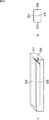
図20に、この実施例を示す。本例は、機器がバッテリーで動作することを想定しており、バッテリーを含めた電子部品がシールドケース571内に収められており、基準電極も兼ねている。電極572は信号電極である。
FIG. 20 shows this embodiment. In this example, it is assumed that the device operates with a battery, and an electronic component including the battery is housed in a
次に、通信媒体について説明する。通信媒体に関しては、これまでの例では、導電体を主な例に挙げたが、導電性を持たない誘電体であっても通信が可能である。誘電体中では、送信信号電極から通信媒体へ注入された電界が、誘電体の分極作用によって伝播するためである。 Next, the communication medium will be described. As for the communication medium, in the examples so far, the conductor has been exemplified as the main example, but communication is possible even with a dielectric having no conductivity. This is because in the dielectric, the electric field injected from the transmission signal electrode to the communication medium propagates due to the polarization action of the dielectric.
具体的に、導電体としては電線等の金属物が、また誘電体としては純水等が考えられるが、両方の性質を併せ持った生体、整理食塩水等でも通信は可能である。また、真空中や空気中も誘電率を持つため、通信媒体として通信可能である。 Specifically, a metal such as an electric wire can be used as the conductor, and pure water or the like can be used as the dielectric. However, communication is possible even with a living body having both properties, or a saline solution. In addition, since it has a dielectric constant in vacuum and air, it can communicate as a communication medium.
次にノイズについて説明する。空間中は、AC電源からのノイズ、蛍光灯や各種家電機器、電気機器からのノイズ、空気中の帯電微粒子の影響等様々な要因によって電位が変動している。これまでは、これら電位変動を無視してきたが、これらのノイズは送信装置、通信媒体、受信装置の各部に重々することになる。 Next, noise will be described. In the space, the potential fluctuates due to various factors such as noise from an AC power source, noise from fluorescent lamps, various home appliances, electrical equipment, and influence of charged fine particles in the air. Until now, these potential fluctuations have been ignored, but these noises overlap each part of the transmission device, communication medium, and reception device.
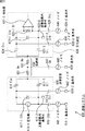
図21は、図1の通信システム100を、ノイズ成分を含めた等価回路により表した模式図である。すなわち、図21の通信システム600は、図9の通信システム500に対応し、通信システム600の送信装置610は、通信システム500の送信装置510に対応し、受信装置620は受信装置520に対応し、接続線630は接続線630に対応する。
FIG. 21 is a schematic diagram showing the communication system 100 of FIG. 1 as an equivalent circuit including a noise component. That is, the communication system 600 of FIG. 21 corresponds to the communication system 500 of FIG. 9, the
送信装置610において、信号源613−1、送信装置内基準点613−2、Cte614、Ctg615、基準点616−1、基準点616−2、Ctb617−1、Cth617−2、およびCti617−3は、それぞれ、送信装置510の、信号源513−1、送信装置内基準点513−2、Cte514、Ctg515、基準点516−1、基準点516−2、Ctb517−1、Cth517−2、およびCti517−3に対応する。ただし、図9の場合と異なり、送信装置610には、ノイズ641およびノイズ642の二つの信号源が、それぞれ、Ctg615と基準点616−1との間、およびCth617−2と基準点616−2との間に設けられている。
In the
受信装置620において、Rr623−1、検出器623−2、受信装置内基準点623−3、Cre624、Crg625、基準点626−1、基準点626−2、Crb627−1、Crh627−2、およびCri627−3は、それぞれ、受信装置520の、Rr523−1、検出器523−2、受信装置内基準点523−3、Cre524、Crg525、基準点526−1、基準点526−2、Crb527−1、Crh527−2、およびCri527−3に対応する。ただし、図9の場合と異なり、受信装置620には、ノイズ644およびノイズ645の二つの信号源が、それぞれ、Crh627−2と基準点626−2との間、およびCrg625と基準点626−1との間に設けられている。
In the receiving device 620, Rr 623-1, detector 623-2, reference point 623-3 in the receiving device,
接続線630において、Rm631、Cm632、Rm633、および基準点636は、それぞれ、接続線530の、Rm531、Cm532、Rm533、および基準点536に対応する。ただし、図9の場合と異なり、接続線630には、信号源により構成されるノイズ643が、Cm532と基準点536との間に設けられている。
In
各装置は、自らが有するグランド電位である送信装置内基準点613−2、または受信装置内基準点623−3を基準に動作しているため、これらに重々するノイズが、送信装置、通信媒体、および受信装置に対して相対的に同成分であれば、動作上は影響しない。一方で、特に装置間の距離が離れている場合やノイズの多い環境下では、各装置間でノイズの相対的な差異を生じる可能性が高まる。つまり、ノイズ641乃至ノイズ645の動きが互いに異なる。この差異も、時間的な変動がない場合には、使用する信号レベルの相対差が伝達されればよいので、問題ないが、ノイズの変動周期が使用する周波数帯に重なるような場合には、そのノイズ特性を考慮して、利用する周波数や信号レベルを定める必要があるが、換言すれば、ノイズ特性を考慮しながら利用する周波数や信号レベルを定めるだけで、通信システム600は、ノイズ成分に対する耐性も有し、物理的な基準点経路を不要とし、通信信号伝達経路のみによる通信を実現することができるので、容易に利用環境の制約を受けない通信環境を提供することができる。 Since each device operates based on the reference point 613-2 in the transmission device or the reference point 623-3 in the reception device, which is the ground potential of the device itself, noise that overlaps with the reference point 613-2 in the transmission device and the communication medium As long as the components are relatively the same with respect to the receiving device, the operation is not affected. On the other hand, particularly when the distance between the devices is large or in a noisy environment, there is a high possibility that a relative difference in noise occurs between the devices. That is, the movements of noise 641 to noise 645 are different from each other. If there is no temporal variation, this difference is not a problem as long as the relative difference in signal level to be used is transmitted, but when the noise fluctuation period overlaps the frequency band used, It is necessary to determine the frequency and signal level to be used in consideration of the noise characteristics. In other words, the communication system 600 can determine the frequency and signal level to be used while considering the noise characteristics. It also has tolerance, can eliminate the need for a physical reference point path, and can realize communication using only the communication signal transmission path, so that it is possible to provide a communication environment that is not easily restricted by the use environment.
次に、送信装置と受信装置の間の距離の大きさによる通信への影響について説明する。上述したように、本発明の原理によれば、送信基準電極と受信基準電極の空間に十分な静電容量を形成できていれば、送受信装置間近辺の大地による経路や、その他の電気的な経路を必要とせず、送信信号電極と受信信号電極の距離に依存しない。従って、例えば、図22に示される通信システム700のように、送信装置710と受信装置720を遠距離におき、十分な導電性あるいは誘電性を持った通信媒体730により送信信号電極711、受信信号電極721を静電的に結合することによって通信が可能である。このとき、送信基準電極712は送信装置710の外部の空間と静電結合し、受信基準電極722は受信装置720の外部の空間と静電結合する。従って、送信基準電極712と受信基準電極722は、互いに静電結合する必要がない。但し、通信媒体730がより長く、大きくなることによって空間に対する静電容量も増加するため、各パラメータを決定する際にこれらについて考慮する必要がある。
Next, the influence on communication due to the distance between the transmission device and the reception device will be described. As described above, according to the principle of the present invention, if a sufficient capacitance can be formed in the space between the transmission reference electrode and the reception reference electrode, a path by the ground in the vicinity between the transmission / reception device and other electrical It does not require a path and does not depend on the distance between the transmission signal electrode and the reception signal electrode. Therefore, for example, as in the communication system 700 shown in FIG. 22, the
なお、図22の通信システム700は、図1の通信システム100に対応するシステムであり、送信装置710は送信装置110に対応し、受信装置720は受信装置120に対応し、通信媒体730は通信媒体130に対応する。
22 is a system corresponding to the communication system 100 in FIG. 1. The
送信装置710において、送信信号電極711、送信基準電極712、および信号源713−1は、それぞれ、送信信号電極111、送信基準電極112、および送信部113(またはその一部)に対応する。同様に、受信装置720において、受信信号電極721、受信基準電極722、および信号源723−1は、それぞれ、受信信号電極121、受信基準電極122、および受信部123(またはその一部)に対応する。
In the
従って、これらの各部についての説明は省略する。 Therefore, the description about each of these parts is omitted.
以上のように通信システム700は、物理的な基準点経路を不要とし、通信信号伝達経路のみによる通信を実現することができるので、利用環境の制約を受けない通信環境を提供することができる。 As described above, the communication system 700 eliminates the need for a physical reference point path and can realize communication using only the communication signal transmission path, so that it is possible to provide a communication environment that is not restricted by the use environment.
なお、以上においては、送信信号電極および受信信号電極が通信媒体と非接触であるように説明したが、これに限らず、送信基準電極および受信基準電極がそれぞれの装置周辺空間との間で十分な静電容量が得られるのであれば、送信信号電極と受信信号電極の間を、導電性を有する通信媒体で接続するようにしてもよい。 In the above description, the transmission signal electrode and the reception signal electrode are described as being in non-contact with the communication medium. However, the present invention is not limited thereto, and the transmission reference electrode and the reception reference electrode are sufficient between the surrounding spaces of the respective devices. If a sufficient electrostatic capacity can be obtained, the transmission signal electrode and the reception signal electrode may be connected by a conductive communication medium.
図23は、送信基準電極および受信基準電極を、通信媒体を介して接続する場合の通信システムの例について説明する模式図である。 FIG. 23 is a schematic diagram illustrating an example of a communication system in a case where a transmission reference electrode and a reception reference electrode are connected via a communication medium.
図23において、通信システム740は、図22の通信システム700に対応するシステムである。ただし、通信システム740の場合、送信装置710に送信信号電極711が存在せず、送信装置710と通信媒体730は、接点741において接続される。同様に、通信システム740における受信装置720には受信信号電極721が存在せず、受信装置710と通信媒体730は、接点742において接続される。
In FIG. 23, a communication system 740 is a system corresponding to the communication system 700 of FIG. However, in the case of the communication system 740, the
通常の有線通信システムでは、少なくとも二つの信号線があり、これらの信号レベルの相対差を利用して通信を行うように成されているが、本発明に従えば、一本の信号線で通信を行うことができる。 In a normal wired communication system, there are at least two signal lines, and communication is performed using a relative difference between these signal levels. However, according to the present invention, communication is performed with one signal line. It can be performed.
つまり、通信システム740も、物理的な基準点経路を不要とし、通信信号伝達経路のみによる通信を実現することができるので、利用環境の制約を受けない通信環境を提供することができる。 That is, the communication system 740 can also provide a communication environment that is not restricted by the use environment, because a physical reference point path is unnecessary and communication can be realized only by the communication signal transmission path.
次に、以上のような通信システムの具体的な適用例について説明する。例えば、以上のような通信システムは、生体を通信媒体とすることもできる。図24は、人体を介して通信を行う場合の通信システムの例を示す模式図である。図24において、通信システム750は、人体の腕部に取り付けられた送信装置760から音楽データを送信し、人体の頭部に取り付けられた受信装置770によってその音楽データを受信して音声に変換し、出力してユーザに視聴させるシステムである。この通信システム750は、上述した通信システム(例えば、通信システム100)に対応したシステムであり、送信装置760や受信装置770は、それぞれ、送信装置110や受信装置120に対応する。また、通信システム750において人体780は、通信媒体であり、図1の通信媒体130に対応する。
Next, a specific application example of the communication system as described above will be described. For example, the communication system as described above can use a living body as a communication medium. FIG. 24 is a schematic diagram illustrating an example of a communication system when communication is performed via a human body. In FIG. 24, the communication system 750 transmits music data from a
つまり、送信装置760は、送信信号電極761、送信基準電極762、および送信部763を有しており、それぞれ、図1の送信信号電極111、送信基準電極112、および送信部113に対応する。また、受信装置770は、受信信号電極771、受信基準電極772、および受信部773を有しており、それぞれ、図1の受信信号電極121、受信基準電極122、および受信部123に対応する。
That is, the
従って、通信媒体である人体780に、送信信号電極761および受信信号電極771が接触または近接されるように、送信装置760および受信装置770が設置される。送信基準電極762および受信基準電極772は、空間に接していればよいので、周辺に大地との結合や、送受信装置(または電極)同士の結合も不要である。
Therefore, the
図25は、通信システム750を実現する他の例について説明する図である。図25において、受信装置770は、人体780に対して足裏部において接触(または近接)し、人体780の腕部に取り付けられた送信装置760との間で通信を行う。この場合も、通信媒体である人体780に接触(または近接)されるように、送信信号電極761と受信信号電極771が設けられ、空間に向けて送信基準電極762と受信基準電極772が設けられている。特に、大地を通信経路の一つとしていた従来技術では実現不可能な応用例である。
FIG. 25 is a diagram for explaining another example for realizing the communication system 750. In FIG. 25, the receiving
つまり、以上のような通信システム750は、物理的な基準点経路を不要とし、通信信号伝達経路のみによる通信を実現することができるので、利用環境の制約を受けない通信環境を提供することができる。 That is, the communication system 750 as described above eliminates the need for a physical reference point path and can realize communication using only the communication signal transmission path, so that it is possible to provide a communication environment that is not restricted by the use environment. it can.
以上のような通信システムにおいて、通信媒体に流す信号の変調方式としては、送信装置と受信装置の両方において対応可能であれば、特に制限はなく、通信システム全体の系の特性を踏まえた上で、最適な方式を選択することが出来る。具体的に変調方式としては、ベースバンド、または振幅変調、または周波数変調されたアナログ信号か、ベースバンド、または振幅変調、または周波数変調、または位相変調されたデジタル信号のうちのいずれか一つ、または複数の混合であってもよい。 In the communication system as described above, there is no particular limitation on the modulation method of the signal flowing in the communication medium as long as it can be handled by both the transmission device and the reception device. Based on the characteristics of the entire communication system, , The most suitable method can be selected. Specifically, the modulation method includes any one of a baseband, amplitude-modulated, or frequency-modulated analog signal, a baseband, amplitude-modulated, frequency-modulated, or phase-modulated digital signal, Alternatively, a plurality of mixtures may be used.
さらに、以上のような通信システムにおいて、一つの通信媒体を利用して、複数の通信を成立させ、全二重通信や、単一の通信媒体による複数の装置同士による通信等を実行することができるようにしてもよい。 Furthermore, in the communication system as described above, it is possible to establish a plurality of communications by using a single communication medium, and execute full-duplex communication, communication between a plurality of devices using a single communication medium, or the like. You may be able to do it.
このような多重通信を実現する方法の例を説明する。一つ目は、スペクトラム拡散方式を適用させる方法である。この場合、送信装置と受信装置の間で互いに周波数帯域幅と特定の時系列コードを取り決めておく。そして送信装置は、この周波数帯域幅の中で、もとの信号を時系列コードによって周波数的に変化させ、周波数帯域全体に拡散させてから送信する。受信装置は、この拡散した成分を受信した後、その受信した信号を積分することで受信信号を復号する。 An example of a method for realizing such multiplex communication will be described. The first is a method of applying a spread spectrum method. In this case, a frequency bandwidth and a specific time series code are negotiated between the transmission device and the reception device. Then, the transmission apparatus changes the frequency of the original signal in accordance with the time-series code within this frequency bandwidth, spreads it over the entire frequency band, and transmits it. After receiving the spread component, the receiving device decodes the received signal by integrating the received signal.
周波数の拡散によって得られる効果を説明する。シャノンとハートレーのチャネル容量の定理によれば、次の式が成り立つ。 The effect obtained by frequency spreading will be described. According to the channel capacity theorem of Shannon and Hartley, the following equation holds.
![]()
![]()
ここで、C[bps]はチャネル容量を示し、通信路に流すことの出来る理論上の最大データレートを示す。B[Hz]はチャネル帯域幅を示す。S/Nは信号対ノイズ電力比(SN比)を示す。さらに、上式をマクローリン展開し、S/Nが低いものとすると、上述した式(23)は、次の式(24)のように近似することができる。 Here, C [bps] indicates the channel capacity, and indicates the theoretical maximum data rate that can be sent to the communication path. B [Hz] indicates the channel bandwidth. S / N indicates a signal-to-noise power ratio (SN ratio). Further, if the above equation is expanded by Macrolin and S / N is low, the above equation (23) can be approximated as the following equation (24).
![]()
![]()
これにより、例えばS/Nがノイズフロア以下のレベルであったとすると、S/N<<1となるが、チャネル帯域幅Bを広げることで、チャネル容量Cを所望のレベルに引き上げることが出来る。 Thus, for example, if S / N is a level below the noise floor, S / N << 1, but by increasing the channel bandwidth B, the channel capacity C can be raised to a desired level.
時系列コードを通信路毎に異なるようし、周波数拡散の動きを異なるようにすれば、相互に干渉することなく周波数が拡散し、相互の混信がなくなることで、同時に複数の通信を行うことができる。 If the time-series code is different for each communication channel and the frequency spread behavior is different, the frequency spreads without interfering with each other and mutual interference is eliminated, so that multiple communications can be performed simultaneously. it can.
図26は、本発明を適用した通信システムの他の構成例を示す図である。図26に示される通信システム800においては、四つの送信装置810−1乃至810−4と、五つの受信装置820−1乃至820−5が、スペクトラム拡散方式を用いて、通信媒体830を介して多重通信を行う。 FIG. 26 is a diagram showing another configuration example of the communication system to which the present invention is applied. In the communication system 800 shown in FIG. 26, four transmission apparatuses 810-1 to 810-4 and five reception apparatuses 820-1 to 820-5 are transmitted via a communication medium 830 using a spread spectrum method. Perform multiplex communication.
送信装置810−1は、図1の送信装置110に対応しており、送信信号電極811、送信基準電極812を有し、さらに、送信部113に対応する構成として、原信号供給部813、乗算器814、拡散信号供給部815、および増幅器816を有している。
The transmission device 810-1 corresponds to the
原信号供給部813は、周波数を拡散する前の信号である原信号を乗算器814に供給する。また、拡散信号供給部815は、周波数を拡散させるための拡散信号を乗算器814に供給する。なお、この拡散信号による拡散の方式には、代表的なものとして、ダイレクトシーケンス方式(以下、DS方式と称する)と周波数ホッピング方式(以下、FH方式と称する)の二種類の方法がある。DS方式は、少なくとも原信号よりも高い周波数成分を持った上記の時系列コードを乗算器814において乗算させ、その乗算結果を所定の搬送波に乗せて、増幅器815において増幅した後出力する方式である。
The original
また、FH方式は、上記の時系列コードによって搬送波の周波数を変化させて拡散信号とし、原信号供給部813より供給される原信号と乗算器814によって乗算し、増幅器815において増幅した後出力する方式である。増幅器815の一方の出力は、送信信号電極811に接続され、他方は、送信基準電極812に接続される。
In the FH system, the carrier wave frequency is changed by the above time-series code to obtain a spread signal, multiplied by the original signal supplied from the original
送信装置810−2乃至送信装置810−4も同様の構成であり、上述した送信装置810−1に対する説明を適用可能であるのでその説明を省略する。 The transmission apparatus 810-2 to the transmission apparatus 810-4 have the same configuration, and the description of the transmission apparatus 810-1 described above can be applied.
受信装置820−1は、図1の受信装置120に対応しており、受信信号電極821、受信基準電極822を有し、さらに、受信部123に対応する構成として、増幅器823、乗算器824、拡散信号供給部825、および原信号出力部826を有している。
The receiving device 820-1 corresponds to the receiving
受信装置820−1は、まず、本発明の方法に基づいて電気信号を復元した後、送信装置810−1と逆の信号処理によって元の原信号(原信号供給部813が供給する信号)を復元する。 The receiving device 820-1 first restores the electrical signal based on the method of the present invention, and then performs the original signal (the signal supplied by the original signal supply unit 813) by signal processing opposite to that of the transmitting device 810-1. Restore.
この方式による周波数スペクトルを図27に示す。横軸は周波数を、縦軸はエネルギーを示している。スペクトル841は周波数を固定した方式のスペクトルであるが、特定の周波数にエネルギーが集中している。この方式では、ノイズフロア843以下にエネルギーが低下してしまうと信号を復元することは出来ない。一方、スペクトル842はスペクトラム拡散方式のスペクトルを示しているが、広い周波数帯域に渡ってエネルギーが分散している。図の長方形の面積が全体のエネルギーを示していると考えることが出来るので、スペクトル842の信号は、各周波数成分がノイズフロア843以下にも関わらず、周波数帯域全体に渡ってエネルギーを積分することで元の信号を復元でき、通信が可能となる。
A frequency spectrum by this method is shown in FIG. The horizontal axis represents frequency and the vertical axis represents energy. The
以上のようなスペクトラム拡散方式を用いて通信を行うことにより、通信システム800は、図26に示されるように、同一の通信媒体830を利用して同時通信を行うことができる。図26において、経路831乃至経路835は通信媒体830上の通信経路を示している。また、スペクトラム拡散方式を用いることにより、通信システム800は、経路831と経路832に示されるような多対一通信や、多対多通信も行うことができる。
By performing communication using the spread spectrum system as described above, the communication system 800 can perform simultaneous communication using the same communication medium 830 as shown in FIG. In FIG. 26,
二つ目は、送信装置と受信装置の間で互いに周波数帯域幅を決め、それをさらに複数の領域に分割する周波数分割方式を適用させる方法である。この場合、送信装置(または受信装置)は、特定の周波数帯域割り振りの規則に従うか、通信開始時に空いている周波数帯域を検出し、その検出結果に基づいて周波数帯域の割り振りを行う。 The second is a method of applying a frequency division method in which a frequency bandwidth is determined between a transmission device and a reception device and is further divided into a plurality of regions. In this case, the transmission device (or the reception device) follows a specific frequency band allocation rule or detects a free frequency band at the start of communication, and performs frequency band allocation based on the detection result.
図28は、本発明を適用した通信システムの他の構成例を示す図である。図28に示される通信システム850においては、四つの送信装置860−1乃至860−4と、五つの受信装置870−1乃至870−5が、周波数分割方式を用いて、通信媒体880を介した多重通信を行う。 FIG. 28 is a diagram showing another configuration example of a communication system to which the present invention is applied. In the communication system 850 shown in FIG. 28, four transmission apparatuses 860-1 to 860-4 and five reception apparatuses 870-1 to 870-5 are connected via a communication medium 880 using a frequency division method. Perform multiplex communication.
送信装置860−1は、図1の送信装置110に対応しており、送信信号電極861、送信基準電極862を有し、さらに、送信部113に対応する構成として、原信号供給部863、乗算器864、周波数可変型発信源865、および増幅器866を有している。
The transmission device 860-1 corresponds to the
周波数可変型発振源865によって生成された特定の周波数成分を持った発振信号は、乗算器864において原信号供給部863より供給された原信号と乗算され、増幅器866において増幅された後、出力される(適宜フィルタリングを行うものとする)。増幅器866の一方の出力は送信信号電極861に接続され、他方は送信基準電極862に接続される。
The oscillation signal having a specific frequency component generated by the variable
送信装置860−2乃至送信装置860−4も同様の構成であり、上述した送信装置860−1に対する説明を適用可能であるのでその説明を省略する。 The transmission apparatuses 860-2 to 860-4 have the same configuration, and the description of the transmission apparatus 860-1 described above can be applied, and thus the description thereof is omitted.
受信装置870−1は、図1の受信装置120に対応しており、受信信号電極871、受信基準電極872を有し、さらに、受信部123に対応する構成として、増幅器873、乗算器874、周波数可変型発信源875、および原信号出力部876を有している。
The receiving device 870-1 corresponds to the receiving
受信装置870−1は、まず、本発明の方法に基づいて電気信号を復元した後、送信装置860−1と逆の信号処理によって元の原信号(原信号供給部863が供給する信号)を復元する。 The receiving device 870-1 first restores the electrical signal based on the method of the present invention, and then performs the original signal (the signal supplied by the original signal supply unit 863) by signal processing opposite to that of the transmitting device 860-1. Restore.
この方式による周波数スペクトルの例を図29に示す。横軸は周波数を、縦軸はエネルギーを示している。なお、ここでは、説明の便宜上、図29に示されるように、全体の周波数帯域幅890(BW)を、五つの帯域幅891乃至895(FW)に分割した例を示している。このように分割された各周波数帯域は、互いに異なる通信経路の通信に利用される。つまり、通信システム850の送信装置860(受信装置870)は、通信経路毎に異なる周波数帯域を利用することにより、図28に示されるように、相互の混信を抑制し、一つの通信媒体880において、同時に複数の通信を行うことができる。図28において、経路881乃至経路885は通信媒体880上の通信経路を示している。また、周波数分割方式を用いることにより、通信システム850は、経路881と経路882に示されるような多対一通信や、多対多通信も行うことができる。
An example of a frequency spectrum by this method is shown in FIG. The horizontal axis represents frequency and the vertical axis represents energy. Here, for convenience of explanation, as shown in FIG. 29, an example is shown in which the entire frequency bandwidth 890 (BW) is divided into five
なお、ここでは、通信システム850(送信装置860または受信装置870)が、全帯域幅890を五つの帯域幅891乃至895に分割するように説明したが、分割数はいくつであってもよいし、各帯域幅の大きさが互いに異なるようにしてもよい。
Here, the communication system 850 (the transmission device 860 or the reception device 870) has been described as dividing the
三つ目は、送信装置と受信装置の間で互いに通信時間を複数に分割する時分割方式を適用させる方法である。この場合、送信装置(または受信装置)は、特定の時間分割規則に従うか、通信開始時に空いている時間領域を検出し、その検出結果に基づいて通信時間の分割を行う。 The third is a method of applying a time division method in which the communication time is divided into a plurality of times between the transmission device and the reception device. In this case, the transmission device (or the reception device) follows a specific time division rule or detects a free time region at the start of communication, and divides the communication time based on the detection result.
図30は、本発明を適用した通信システムの他の構成例を示す図である。図30に示される通信システム900においては、四つの送信装置910−1乃至910−4と、五つの受信装置920−1乃至920−5が、時分割方式を用いて、通信媒体930を介した多重通信を行う。 FIG. 30 is a diagram showing another configuration example of the communication system to which the present invention is applied. In the communication system 900 shown in FIG. 30, four transmission apparatuses 910-1 to 910-4 and five reception apparatuses 920-1 to 920-5 are connected via a communication medium 930 using a time division method. Perform multiplex communication.
送信装置910−1は、図1の送信装置110に対応しており、送信信号電極911、送信基準電極912を有し、さらに、送信部113に対応する構成として、時間制御部913、乗算器914、発信源915、および増幅器916を有している。
The transmission device 910-1 corresponds to the
時間制御部913によって所定時間に原信号が出力される。乗算器914は、原信号と、発振源915により供給される発振信号を乗算し、増幅器916から出力する(適宜フィルタリングを行うものとする)。増幅器916の一方の出力は、送信信号電極911に接続され、他方は、送信基準電極912に接続される。
The
送信装置910−2乃至送信装置910−4も同様の構成であり、上述した送信装置910−1に対する説明を適用可能であるのでその説明を省略する。 The transmission apparatuses 910-2 to 910-4 have the same configuration, and the description of the transmission apparatus 910-1 described above can be applied.
受信装置920−1は、図1の受信装置120に対応しており、受信信号電極921、受信基準電極922を有し、さらに、受信部123に対応する構成として、増幅器923、乗算器924、発信源925、および原信号出力部926を有している。
The reception device 920-1 corresponds to the
受信装置920−1は、まず、本発明の方法に基づいて電気信号を復元した後、送信装置920−1と逆の信号処理によって元の原信号(時間制御部913が供給する原信号)を復元する。 The receiving device 920-1 first restores the electrical signal based on the method of the present invention, and then performs the original signal (original signal supplied by the time control unit 913) by signal processing reverse to that of the transmitting device 920-1. Restore.
この方式によるる時間軸上のスペクトルの例を図31に示す。横軸は時間を、縦軸はエネルギーを示している。なお、ここでは、説明の便宜上、五つの時間帯域941乃至945を示しているが、実際には、時間帯域は、これ以降同様に継続する。このように分割された各時間帯域は、互いに異なる通信経路の通信に利用される。つまり、通信システム900の送信装置910(受信装置920)は、通信経路毎に異なる時間帯域において通信を行うことにより、図30に示されるように、相互の混信を抑制し、一つの通信媒体930において、同時に複数の通信を行うことができる。図30において、経路931乃至経路935は通信媒体930上の通信経路を示している。また、時分割方式を用いることにより、通信システム900は、経路931と経路932に示されるような多対一通信や、多対多通信も行うことができる。
An example of the spectrum on the time axis according to this method is shown in FIG. The horizontal axis indicates time, and the vertical axis indicates energy. Here, for convenience of explanation, five
なお、ここでは、通信システム900(送信装置910または受信装置920)が分割する各時間帯の時間幅の大きさが互いに異なるようにしてもよい。 Here, the time widths of the respective time zones divided by the communication system 900 (the transmission device 910 or the reception device 920) may be different from each other.
さらに、上述した以外の方法として、一つ目から三つ目までの通信方式のうちの二つ以上を組み合わせるようにしてもよい。 Furthermore, as a method other than those described above, two or more of the first to third communication methods may be combined.
送信装置および受信装置が、同時に複数の他の装置と通信を行うことができるということは、特定のアプリケーションにおいては、特に重要になる。例えば、交通機関のチケットへの応用を想定すると、定期券の情報を有する装置Aと電子マネー機能を有する装置Bの両方を所持した利用者が、自動改札機を利用する際、上記のような方式を使用することで、装置A及び装置Bと同時に通信することで、例えば、利用区間が定期券外の区間も含まれていた場合に、不足金額分を装置Bの電子マネーから差し引くといった便利な用途に利用することが出来る。 The ability of a transmitting device and a receiving device to communicate with multiple other devices at the same time is particularly important in certain applications. For example, assuming application to a ticket for transportation facilities, when a user who possesses both a device A having commuter pass information and a device B having an electronic money function uses an automatic ticket gate, By using the method, communication is performed simultaneously with the devices A and B. For example, when the use section includes a section other than the commuter pass, the shortage amount is deducted from the electronic money of the apparatus B. It can be used for various purposes.
以上のような送信装置と受信装置との間の通信において実行される通信処理の流れについて、図1の通信システム100の送信装置110と受信装置120との通信の場合を例に、図32のフローチャートを参照して説明する。
The flow of communication processing executed in the communication between the transmission apparatus and the reception apparatus as described above, taking the case of communication between the
送信装置110の送信部113は、ステップS1において、送信対象となる信号を発生し、ステップS2において、その発生した信号を、送信信号電極111を介して、通信媒体130上に送信する。信号を送信すると送信装置の送信部113は、通信処理を終了する。送信装置110より送信された信号は、通信媒体130を介して受信装置120に供給される。受信装置120の受信部123は、ステップS21において、受信信号電極121を介して、その信号を受信し、ステップS22において、その受信した信号を出力する。受信した信号を出力した受信部123は、通信処理を終了する。
The
以上のように、送信装置110および受信装置120は、基準電極を用いて閉回路を構築する必要がなく、信号電極を介して信号を送受信するのみで、環境に影響されずに安定した通信処理を容易に行うことができる。なお、通信処理の構造が単純であるので、通信システム100は、変調、符号化、暗号化、または多重化など、多様な通信方式を容易に併用することができる。
As described above, the
なお、以上の通信システムにおいては、送信装置と受信装置を別体として構成するように説明したが、これに限らず、上述した送信装置と受信装置の両方の機能を有する送受信装置を用いて通信システムを構築するようにしてもよい。 In the above communication system, the transmission device and the reception device are described as separate units. However, the present invention is not limited to this, and communication is performed using the transmission / reception device having the functions of both the transmission device and the reception device described above. A system may be constructed.
図33は、本発明を適用した通信システムの他の構成例を示す図である。 FIG. 33 is a diagram showing another configuration example of a communication system to which the present invention is applied.
図33において、通信システム950は、送受信装置961、送受信装置962、および通信媒体130を有する。通信システム950は、送受信装置961と送受信装置962が通信媒体130を介して双方向に信号を送受信するシステムである。
In FIG. 33, the communication system 950 includes a transmission / reception device 961, a transmission / reception device 962, and a
送受信装置961は、図1の送信装置110と同様の送信部110と、受信装置120と同様の受信部120の両方の構成を有している。すなわち、送受信装置961は、送信信号電極111、送信基準電極112、送信部113、受信信号電極121、受信基準電極122、および受信部123を有している。
The transmission / reception device 961 has both the configuration of the
つまり送受信装置961は、送信部110を用いて通信媒体130を介して信号を送信し、受信部120を用いて通信媒体130を介して供給される信号を受信する。上述したように、本発明の通信方式においては多重通信が可能であるので、この場合の送受信装置961においても、送信部110による通信と、受信部120による通信とを同時に(時間的に重なるように)行われるようにしてもよい。
That is, the transmission / reception device 961 transmits a signal via the
送受信装置962は、送受信装置961と同様の構成を有し、同様に動作するのでその説明を省略する。つまり送受信装置961と送受信装置962は、互いに同様の方法で、通信媒体130を介して、双方向に通信を行う。
The transmission / reception device 962 has the same configuration as that of the transmission / reception device 961 and operates in the same manner, and thus the description thereof is omitted. That is, the transmission / reception device 961 and the transmission / reception device 962 perform bidirectional communication via the
このようにすることにより、通信システム950(送受信装置961および送受信装置962)は、利用環境に制約を受けない双方向通信を容易に実現することができる。 In this way, the communication system 950 (the transmission / reception device 961 and the transmission / reception device 962) can easily realize bidirectional communication that is not restricted by the usage environment.
なお、この送受信装置961や送受信装置962の場合も、図23を参照して説明した送信装置や受信装置の場合と同様に、送信信号電極や受信信号電極を通信媒体に電気的に接続する(接点741または接点742として設ける)ようにしてももちろんよい。また、以上においては送信信号電極111、送信基準電極112、受信信号電極121、および受信基準電極122を互いに別体として構成するように説明したが、これに限らず、例えば、送信信号電極111と受信信号電極121を一つの電極により構成するようにしてもよいし、また、送信基準電極112と受信基準電極122を一つの電極により構成する(送信部113および受信部123が信号電極または基準電極を共有する)ようにしてもよい。
In the case of the transmission / reception device 961 and the transmission / reception device 962, the transmission signal electrode and the reception signal electrode are electrically connected to the communication medium as in the case of the transmission device and the reception device described with reference to FIG. Of course, the contact 741 or the contact 742 may be provided. In the above description, the
尚、以上において、本発明を適用した通信システムの各装置(送信装置、受信装置、および通信装置)は、各装置内の基準電位が基準電極と接続されるように説明したが、これに限らず、例えば、互いに位相が異なる二つの信号で動作する差動回路により構成してもよく、差動回路の一方の信号を信号電極に接続して通信媒体中に伝送し、差動回路の他方の信号を基準電極に接続することによっても情報の伝送が可能である。 In the above description, each device (transmitting device, receiving device, and communication device) of the communication system to which the present invention is applied has been described so that the reference potential in each device is connected to the reference electrode. For example, it may be configured by a differential circuit that operates with two signals having different phases from each other. One signal of the differential circuit is connected to the signal electrode and transmitted into the communication medium, and the other of the differential circuit is transmitted. Information can also be transmitted by connecting the above signal to the reference electrode.
次に、本発明を適用した通信システムについて説明する。図34は、本発明を適用した通信システムの一実施形態に係る構成例を示す図である。 Next, a communication system to which the present invention is applied will be described. FIG. 34 is a diagram showing a configuration example according to an embodiment of a communication system to which the present invention is applied.
図34に示される通信システム1000は、リーダライタ1001とユーザデバイス1002がユーザ1003(人体)を介して通信を行う通信システムであり、以上に説明したような、基準電極を用いて閉回路を構築する必要がなく、信号電極を介して信号を送受信するのみで、環境に影響されずに安定した通信処理を容易に行う通信システムである。つまり、通信システム1000は、図1の通信システム100と同様の方法により通信を行う通信システムである。
The communication system 1000 shown in FIG. 34 is a communication system in which the reader /
リーダライタ1001は、例えば、駅、商店、銀行等の所定の施設に設置され、例えば改札処理、代金支払い処理、残高照会処理等の、所定のサービスをユーザ1003に提供する装置である。ユーザデバイス1002は、ユーザ1003が所持する携帯型の通信装置であり、リーダライタ1001と人体を介した通信を行うことができる通信装置である。ユーザデバイス1002は、例えば、ユーザ1003の腕にベルト等を用いて通信可能に固定される。後述するようにリーダライタ1001は、ユーザデバイス1002を所持したまま、リーダライタ1001の所定の位置に接触(近接も含む)したユーザ1003を介してそのユーザデバイス1002と通信を行い、ユーザ1003(ユーザデバイス1002)に対して所定のサービスを提供する。なお、以下の説明においても、「接触」は、「近接」する(すなわち、通信可能な範囲内に位置する)ことも含むものとする。
The reader /
図35は、リーダライタ1001の内部の構成例を示すブロック図である。
FIG. 35 is a block diagram illustrating an internal configuration example of the reader /
リーダライタ1001は、通信部1011、通信最適化部1012、およびサービス処理部1013を有している。
The reader /
通信部1011は、人体(図35の例の場合、ユーザ1003)を介して行う、ユーザデバイス1002との通信に関する処理を行う。通信部1011は、送受信部1021、基準電極1022、および信号電極1023を有しており、信号電極1023に接触したユーザ1003を介して、そのユーザ1003が所持するユーザデバイス1002との通信を行う。
The
つまり、例えば、リーダライタ1001の筐体に、信号電極1023(送受信部1021に接続される2つの電極のうち、一方の電極)に触れるように指示する、サービス提供対象のユーザ1003に対するメッセージが表示または記載されており、ユーザデバイス1002を所持するユーザ1003は、その指示に従って信号電極1023に触れる。この状態において、リーダライタ1001の通信部1011は、信号電極1023からユーザ1003の人体を介したユーザデバイス1002との通信を行う。
That is, for example, a message for the service providing
すなわち、図35の送受信部1021は、例えば送信部113や受信部123に対応し、基準電極1022は例えば送信基準電極112や受信基準電極122に対応し、信号電極1023は例えば送信信号電極111や受信信号電極121に対応する。つまり、信号電極1023と通信媒体となる人体(図35の例の場合ユーザ1003)との間に形成される静電容量は、基準電極1022と通信媒体(人体)との間に形成される静電容量に対して大きい。
35 corresponds to, for example, the
送受信部1021は、送信信号を発生したり、信号電極1023より受信した信号を検出したりする。通信最適化部1012は、送受信部1021に接続されており、送受信部1021による通信に関する設定を用途(処理内容)や機能に応じて最適化し、その最適化した設定に基づいて送受信部1021を制御し、より好ましい方法(設定)で通信処理を実行させる。また、サービス処理部1013は、送受信部1021に接続されており、その送受信部1021が実行する、通信最適化部1012が設定を最適化した通信処理を利用して提供するサービスに関する処理を行う。
The transmission /
図36は、通信最適化部1012の詳細な構成例を示すブロック図である。
FIG. 36 is a block diagram illustrating a detailed configuration example of the
図36において、通信最適化部1012は、保持部1031、情報共有部1032、設定部1033、通信制御部1034、表示制御部1035、および表示部1036を有している。
36, the
保持部1031は、例えば、半導体メモリやハードディスク等の記録媒体(記憶領域)を有しており、リーダライタ1001の機能や用途等に関する情報であるリーダライタ属性情報を保持する。このリーダライタ属性情報の詳細については後述する。保持部1031は、例えば、情報共有部1032の要求に基づいて、保持しているリーダライタ属性情報を情報共有部1032に供給する。
The
情報共有部1032は、リーダライタ1001と通信可能な状態のユーザデバイス1002と属性情報を共有するための処理を行う。例えば、情報共有部1032は、ユーザデバイス1002からの要求に基づいて、保持部1031に保持されているリーダライタ属性情報を取得し、ユーザデバイス1002に供給する。また、例えば、情報共有部1032は、ユーザデバイス1002に対してユーザデバイスの属性情報であるユーザデバイス属性情報を要求し、その要求に応じて供給されるユーザデバイス属性情報を取得し、それを設定部1033に供給する。情報共有部1032の詳細については後述する。
The
設定部1033は、通信処理に関する設定を行う処理部であり、情報共有部1032より供給されるユーザデバイス属性情報に基づいてその設定を行い、その設定結果を通信制御部1034や表示制御部1035に供給する。設定部1033の詳細については後述する。
The
通信制御部1034は、設定部1033より供給される設定値に基づいて、通信部1011を制御する。通信制御部1034の詳細については後述する。また、表示制御部1035は、表示部1036を制御し、必要に応じて、設定部1033より供給される設定値に関する情報(メッセージ等)を表示させる。
The
例えば、通信処理を安定的に行う場合、表示制御部1035は、「カードをしっかり当ててください。」等の、ユーザ1003に向けのメッセージを表示部1036に表示する。また、例えば、ユーザデバイス1002の電源の電力が不足している(残容量が少ない)場合、表示制御部1035は、「処理時間がかかります。暫くお待ちください。」等の、ユーザ1003に向けのメッセージを表示部1036に表示する。
For example, when the communication process is stably performed, the
表示部1036は、例えば、液晶表示装置(LCD(Liquid Crystal Display))、有機エレクトロルミネセント表示装置(有機ELディスプレイ(Organic ElectroLuminescence Display))、電界発光表示装置(FED(Field Emission Display))、プラズマディスプレイパネル(PDP(Plasma Display Panel))、エレクトロクロミック表示装置(Electro Chromic Display)、蛍光表示管を用いた表示装置、陰極線管を用いた表示装置、プロジェクタ等の表示機能を有するデバイスを有し、表示制御部1035の制御に基づいて、メッセージや画像等を表示する。
The
次に、図36に示される各部の詳細な構成例について説明する。 Next, a detailed configuration example of each unit illustrated in FIG. 36 will be described.
図37は、図36の保持部1031が保持する情報の構成例を示す模式図である。
FIG. 37 is a schematic diagram showing a configuration example of information held by the
図37において、保持部1031は、リーダライタ1001の機能や用途等に関する情報であるリーダライタ属性情報1040を保持している。リーダライタ属性情報1040は、リーダライタ1001の機能(ハードウェア制限)に関する情報であるリーダライタハードウェア属性情報1041、および、リーダライタ1001の用途(ソフトウェア)に関する情報であるリーダライタソフトウェア属性情報1042を含む。
In FIG. 37, the
リーダライタハードウェア属性情報1041は、例えば、図38Aに示されるように、項目情報とその属性値により構成されるテーブル情報である。項目としてはハードウェアが有する機能の種類、例えば、通信に関する処理の速度(動作周波数)の設定に関する能力を示す「処理速度」、信号送信能力を示す「送信パワー」、信号受信能力を示す「受信感度」、ユーザデバイス1002に電力を供給可能か否かを示す「給電能力」等がある。属性値としては例えば、各項目の能力(ハードウェアの能力限界)を示す値が適用される。図38Aの場合、属性値は、対応する項目の属性値が最低レベルに固定されている(固定値である)ことを示す値「0」、対応する項目の属性値が中レベルに固定されている(固定値である)ことを示す値「1」、対応する項目の属性値が最高レベルに固定されている(固定値である)ことを示す値「2」、または、対応する項目の属性値が可変であることを示す値「3」、のいずれかが割り当てられる。なお、この値「0」乃至「3」で区分する区分方法は、「給電能力」の項目に対する属性値には適用されない。「給電能力」の項目に対する属性値には、例えば、給電能力を有していないことを示す値「0」、または、給電能力を有することを示す値「1」のいずれかが割り当てられる。
The reader / writer
なお、図38Aにおいては、属性値として割り当てられる値の例が1つ示されているが、実際には、各項目に対してそれぞれ属性値(図38Aの例の場合、「0」乃至「3」のいずれか)が割り当てられる。もちろん、属性値は、どのような値であってもよく、また、各値がどのようなものを示すものであってもよい。さらに、各項目に割り当てられる属性値の示す内容が互いに異なるものであってもよい。例えば、図38Aの例において、処理速度から受信感度までの項目の属性値には、図38Aに示される値のいずれかが割り当てられ、一番下の項目「給電能力」に対する属性値のみ、給電能力を有していないことを示す値「0」、または、給電能力を有することを示す値「1」のいずれかが割り当てられるようにしてもよい。 In FIG. 38A, one example of values assigned as attribute values is shown. Actually, however, attribute values (in the example of FIG. 38A, “0” to “3” are assigned to each item. ")" Is assigned. Of course, the attribute value may be any value, and each value may indicate what. Furthermore, the contents indicated by the attribute values assigned to the items may be different from each other. For example, in the example of FIG. 38A, any of the values shown in FIG. 38A is assigned to the attribute values of the items from the processing speed to the reception sensitivity, and only the attribute value for the bottom item “power supply capability” is supplied. Either a value “0” indicating that the device has no capability or a value “1” indicating that the device has power supply capability may be assigned.
リーダライタソフトウェア属性情報1042は、例えば、図38Bに示されるように、項目情報とその属性値により構成されるテーブル情報である。項目情報はリーダライタ1001が提供するサービス(リーダライタ1001の用途)の種類を示す情報、すなわち、リーダライタ1001が実行するソフトウェアの内容を示す情報である。例えば、図38Bに示されるように、「改札処理」、「支払い処理」、「残高照会処理」などがある。この項目情報は、例えば、リーダライタ1001が提供するサービス全体を示すものであってもよいし、サービスに含まれる詳細な処理(例えば、通信、課金、表示等)を示す情報であっても良いし、それらの両方を含むようにしてもよい(つまり、各項目が示す内容が階層化されていてもよい)。
The reader / writer
属性値としては、各項目(用途)毎のハードウェアの設定(例えば上述した「処理速度」、「送信パワー」、「受信感度」、および「給電能力」などの設定値の組み合わせ)を示す値が割り当てられる。この値はどのような値であってもよい。なお、ここでは「処理速度」、「送信パワー」、「受信感度」、および「給電能力」は、ハードウェアの能力限界を示すものではなく、設定項目の種類を示している。つまり、例えば、図38Bの例においては、リーダライタソフトウェア属性情報1042の「残高照会処理」の項目に対して「処理速度:低速、送信パワー:弱、受信感度:強、給電能力:無」ということを示す値が属性値として割り当てられていることが示されているが、この属性値は、このリーダライタ1001の処理速度が「低速」であることを示しているのではなく、残高照会処理においては、処理速度が「低速」に設定されることを示している。従って、各項目(用途)により、同じ要素の属性値が互いに異なる(例えば、「処理速度」の値が「低速」であったり、「高速」であったりする)こともある。その他の要素についても同様である。
As an attribute value, a value indicating a hardware setting for each item (use) (for example, a combination of setting values such as “processing speed”, “transmission power”, “reception sensitivity”, and “power supply capability” described above) Is assigned. This value may be any value. Here, “processing speed”, “transmission power”, “reception sensitivity”, and “power supply capability” do not indicate the capability limit of hardware, but indicate types of setting items. That is, for example, in the example of FIG. 38B, “processing speed: low speed, transmission power: weak, reception sensitivity: strong, power supply capability: none” for the “balance inquiry processing” item of the reader / writer
これは実行される処理(用途)により、最適な処理方法が必ずしも互いに一致しないからである。つまり、例えば、「改札処理」においては、次々とユーザが通過するので、高速に処理を行う必要がある。従って、図38Bの例においては、処理速度は高速に設定されている。さらに、通信可能範囲が広くなるように、送信パワーおよび受信感度は強く設定されている。これに対して例えば「支払い処理」においては、処理速度は比較的遅くてもよいが、通信処理の確実性が求められる。また、安全性の面から処理対象のユーザを確実に限定する必要もあるので通信範囲も意図的に限定する必要がある。従って、図38Bの例においては、処理速度は遅く設定され、送信パワーは弱く設定されているが、受信感度は強く設定されている。このように、リーダライタソフトウェア属性情報1042の属性値には、各用途に応じて各機能(要素)を最適化するための設定値が予め割り当てられている。
This is because the optimum processing methods do not necessarily match each other depending on the processing (use) to be executed. That is, for example, in the “ticket gate process”, since the user passes one after another, it is necessary to perform the process at high speed. Therefore, in the example of FIG. 38B, the processing speed is set to a high speed. Furthermore, the transmission power and the reception sensitivity are set strongly so that the communicable range is widened. On the other hand, for example, in the “payment process”, the processing speed may be relatively slow, but certainty of the communication process is required. Moreover, since it is necessary to restrict | limit the user of a process target reliably from a safety surface, it is also necessary to intentionally limit the communication range. Therefore, in the example of FIG. 38B, the processing speed is set to be slow and the transmission power is set to be weak, but the reception sensitivity is set to be strong. As described above, setting values for optimizing each function (element) according to each application are assigned in advance to the attribute values of the reader / writer
なお、属性値が示す設定の要素の内容は、図38Bに示される以外のものであってももちろんよく、各要素に割り当てられる値も任意である。 Note that the content of the setting element indicated by the attribute value may be anything other than that shown in FIG. 38B, and the value assigned to each element is also arbitrary.
図37に戻り、以上のようなリーダライタハードウェア属性情報1041およびリーダライタソフトウェア属性情報1042を含むリーダライタ属性情報1040を保持する保持部1031は、情報共有部1032の要求に基づいて、それらの情報を提供する。
Returning to FIG. 37, the
なお、リーダライタ属性情報1040は、リーダライタハードウェア属性情報1041およびリーダライタソフトウェア属性情報1042のうち、少なくとも一方を含んでいればよい。また、保持部1031は、保持するリーダライタ属性情報1040を全て情報共有部1032に供給するようにしてもよいが、情報共有部1032に要求された情報のみを供給するようにしてもよい。つまり、保持部1031は、リーダライタ属性情報1040の一部(リーダライタハードウェア属性情報1041の一部、リーダライタソフトウェア属性情報1042の一部、またはそれらを組み合わせたもの)のみを保持している情報の中から抽出して情報共有部1032に供給することができる。なお、保持部1031が、情報共有部1032からの要求以外の、所定のタイミングやきっかけに基づいて情報を情報共有部1032に供給するようにしてもよい。
The reader /
図39は、図36の情報共有部1032の詳細な構成例を示すブロック図である。
FIG. 39 is a block diagram illustrating a detailed configuration example of the
図39において、情報共有部1032は、要求受付部1051、情報供給部1052、要求部1053、および情報取得部1054を有している。
39, the
要求受付部1051は、通信部1011を制御し、他のデバイス(図34の例の場合、ユーザデバイス1002)より供給されるリーダライタ属性情報1040の要求を受け付ける処理を行う。そして、その要求を受け付けると、要求受付部1051は、そのことを情報供給部1052に通知する。
The
情報供給部1052は、通信部1011を制御し、リーダライタ属性情報を他のデバイス(図34の例の場合、ユーザデバイス1002)に供給する処理を行う。例えば、要求受付部1051よりリーダライタ属性情報1040の要求を受け付けた旨を通知されると、情報供給部1052は、保持部1031に保持されている情報の中から、その受け付けた要求により要求されたリーダライタ属性情報1040を読み出し、通信部1011を制御して、読み出したリーダライタ属性情報1040を要求元(図34の例の場合、ユーザデバイス1002)に供給させる。
The
要求部1053は、所定のタイミングで通信部1011を制御し、通信可能な他のデバイス(図34の例の場合、ユーザデバイス1002)に対して属性情報の要求を送信させる。要求部1053が属性情報の要求を送信させるタイミングは、どのようなタイミングであってもよく、例えば、所定のイベントをきっかけとして要求を送信させるようにしてもよいし、自発的に、周期的または非周期的に要求を送信させるようにしてももちろんよい。要求部1053は、要求を送信させると、その旨を情報取得部1054に通知する。
The
情報取得部1054は、例えば要求部1053より通知を受けると、通信部1011を制御し、属性情報の取得を開始する。そして、通信部1011を介して属性情報を取得すると、それを設定部1033に供給する。
For example, when receiving a notification from the
なお、要求受付部1051および要求部1053は、いずれか一方または両方を省略するようにしてもよい。例えば、要求受付部1051を省略し、情報供給部1052が、所定のタイミングにおいて、または所定のイベントをトリガとして、保持部1031よりリーダライタ属性情報1040を取得し、通信部1011を制御してそれを他のデバイス(図34の例の場合、ユーザデバイス1002)に送信するようにしてもよい。また、例えば、要求部1053を省略し、情報取得部1054が、常に通信部1011を制御して他のデバイス(図34の例の場合、ユーザデバイス1002)の属性情報(ユーザデバイス属性情報)を受け付け、他のデバイスより供給された属性情報を取得するとそれを設定部1033に供給するようにしてもよい。
Note that either one or both of the
さらに、情報取得部1054は、保持部1031に保持されているリーダライタ属性情報1040も取得し、それを設定部1033に供給するようにしてもよい。すなわち、この場合、設定部1033は、他のデバイスの属性情報(例えば、ユーザデバイス属性情報)だけでなく、リーダライタ1001自身の属性情報(リーダライタ属性情報1040)も用いて通信の設定を行う。
Further, the
図40は、図36の設定部1033の詳細な構成例を示すブロック図である。
FIG. 40 is a block diagram illustrating a detailed configuration example of the
図40において、設定部1033は、ユーザデバイス設定変更可否確認部1061、リーダライタ設定部1062、および設定テーブル保持部1063を有している。
40, the
ユーザデバイス設定変更可否確認部1061は、情報共有部1032より供給される他のデバイスの属性情報(ユーザデバイス属性情報)、または、他のデバイス属性情報とリーダライタ1001自身の属性情報の両方に基づいて、通信相手となる他のデバイスであるユーザデバイスが設定を変更可能か否かを確認する。
The user device setting change enable / disable confirmation unit 1061 is based on the attribute information (user device attribute information) of another device supplied from the
例えば、ユーザデバイス1002の処理速度の設定が変更不可能であるような場合、通信処理を確実に行うために、リーダライタ1001の処理速度の設定範囲に制限が必要になることが考えられる。また、例えば、ユーザデバイス1002の送信パワーの設定値が低すぎる場合であっても、ユーザデバイス1002の設定値が固定値であれば、ユーザデバイス1002の送信パワーを強くする代わりに、リーダライタ1001の受信感度を上げる必要が生じることがある。
For example, when the setting of the processing speed of the
このように、通信相手のデバイス(ユーザデバイス)の属性値が変更可能か否かによってリーダライタの1001の属性値の設定方法が変わる恐れがある。従って、ユーザデバイス設定変更可否確認部1061は、ユーザデバイスが設定を変更可能か否かを確認し、その確認結果を、ユーザデバイス属性情報とともにリーダライタ設定部1062に供給する。
As described above, the method for setting the attribute value of the reader /
なお、上述したように、ユーザデバイス設定変更可否確認部1061が、ユーザデバイスが設定を変更可能か否かを確認する際に、リーダライタ1001自身の属性情報であるリーダライタ属性情報1040も参照することにより、リーダライタ1001側でその属性値に対応する設定を変更可能か否かをさらに確認するようにしてもよい。その場合、ユーザデバイス設定変更可否確認部1061は、その確認結果を、ユーザデバイス属性情報およびリーダライタ属性情報1040とともにリーダライタ設定部1062に供給する。
As described above, when the user device setting change permission confirmation unit 1061 confirms whether the user device can change the setting, the reader /
リーダライタ設定部1062は、設定テーブル保持部1063に保持されている設定テーブル1071を取得し、その設定テーブル1071、並びに、ユーザデバイス設定変更可否確認部1061より供給されるユーザデバイス属性情報および設定変更可否確認結果に基づいて設定を行う。設定テーブル1071は、後述するように、条件に応じて設定値を選択するためのテーブル情報であり、リーダライタ設定部1062は、その設定テーブル1071において、ユーザデバイス属性情報および設定変更可否確認結果に対応する設定を選択する。リーダライタ設定部1062は、必要に応じて、その設定結果を通信制御部1034および表示制御部1035のうち、少なくとも一方に供給する。
The reader /
なお、ユーザデバイス設定変更可否確認部1061が、確認結果とともに、ユーザデバイス属性情報およびリーダライタ属性情報1040を供給する場合、リーダライタ設定部1062は、ユーザデバイス属性情報およびリーダライタ属性情報1040の両方(またはいずれか一方を選択し、その選択した属性情報)、並びに設定テーブル1071に基づいて設定を行うようにすることができる。
When the user device setting change enable / disable confirmation unit 1061 supplies the user device attribute information and the reader /
設定テーブル保持部1063は、例えば、半導体メモリやハードディスク等の記録媒体(記憶領域)を有しており、図41に示されるように、リーダライタ1001の通信に関する設定を行うためのテーブル情報である設定テーブル1071を保持する。
The setting
図41は、設定テーブル1071の構成例を示す模式図である。 FIG. 41 is a schematic diagram illustrating a configuration example of the setting table 1071.
図41の例の場合、設定テーブル1071は、図中縦方向に、今回利用される用途毎に分類されており、「改札処理」、「支払い処理」、および「残高照会処理」の3つの用途が示されている。また、設定テーブル1071は、図中横方向にユーザデバイス1002のハードウェア制限毎に分類されており、電源を持たない「外部電源型ユーザデバイス」、電力十分な電源を備えている「電源内蔵型ユーザデバイス(電力十分な状態)」、および、電源を備えているがその電力が不足している状態の「電源内蔵型ユーザデバイス(電力不足状態)」の3つのハードウェア制限に分類されている。
In the case of the example of FIG. 41, the setting table 1071 is classified in the vertical direction in the figure for each usage used this time, and has three usages of “ticket gate processing”, “payment processing”, and “balance inquiry processing”. It is shown. Further, the setting table 1071 is classified in the horizontal direction in the figure for each hardware restriction of the
これらの条件により分類される各状態には、それぞれ設定値が割り当てられている。リーダライタ設定部1062は、この設定テーブル1071を用いて、通信の設定を選択する。なお、その際、リーダライタ設定部1062は、設定変更可否確認結果やリーダライタ1001自身の機能も考慮しながら通信の設定を選択する。
A set value is assigned to each state classified by these conditions. The reader /
このようにすることにより、リーダライタ1001は、例えば、電源を持たないユーザデバイス1002に対しては電力を供給し、電源内蔵型のユーザデバイス1002に対しては電力の供給を停止する等、適切な電力供給制御を行うことができ、消費電力を抑制することができる。
In this way, the reader /
また、リーダライタ1001は、例えば、ユーザデバイス1002が電源を有していなかったり、電力不足だったりする場合、処理速度を低下させたり、送信パワーを強くしたり、受信感度を強くしたりして、ユーザデバイス1002の処理速度が低速で、送信パワーや受信感度が弱くても通信することができるように設定することができる。
Also, the reader /
さらに、リーダライタ1001は、例えば、用途(処理の内容)が残高照会処理の場合、受信感度を弱くする等して、通信範囲を制限することができる。
Furthermore, for example, when the application (contents of processing) is balance inquiry processing, the reader /
以上のように設定処理を行うことにより、リーダライタ1001は、用途やハードウェア制限等に基づいて、最適な設定を選択することができ、例えば、リーダライタ1001やユーザデバイス1002の消費電力を抑制したり、通信の確実性を向上させたり、通信範囲を制御して通信の安全性を向上させたり、通信処理時間を短縮したりすることができる。
By performing the setting process as described above, the reader /
つまり、リーダライタ1001は、通信最適化部1012により最適化された通信処理を利用してサービスを提供することができる。
That is, the reader /
なお、どのような効果が通信にとって最適となるかは、各通信に応じて異なる場合がある。例えば、支払い処理の場合、処理速度よりも通信の確実性や安全性が重要になるが、改札処理の場合、処理速度の高速化が求められる。また、ユーザデバイス1002のタイプによっては、消費電力の大小が最も重要になることもある。さらに、通信をより確実に行うように制御する場合であっても、処理速度を落とした方が良い場合、送信パワーをあげた方が良い場合、受信感度を上げた方が良い場合等、状況により最適な方法が異なる場合がある。設定テーブル1071には、このように任意の条件毎に、予め設定された最適な通信設定が登録されている。
Note that what effect is optimal for communication may differ depending on each communication. For example, in the case of payment processing, the certainty and security of communication are more important than the processing speed, but in the case of ticket gate processing, it is required to increase the processing speed. Further, depending on the type of the
つまり、上述した設定テーブル1071に登録される評価要素はあくまでも一例であり、例えば、通信のリアルタイム性やデバイスの製造コスト等、その他の評価要素が登録されるようにしてもよく、条件毎にその評価要素が異なるようにしてもよい。設定テーブル1071により設定される内容は、予め各条件に対して割り当てられるものであればどのようなものであってもよく、どのような評価要素において効果を得るものであってもよい。 That is, the evaluation elements registered in the setting table 1071 described above are merely examples. For example, other evaluation elements such as real-time communication characteristics and device manufacturing costs may be registered. The evaluation factors may be different. The content set by the setting table 1071 may be anything as long as it is assigned in advance to each condition, and may be effective in any evaluation element.
なお、設定テーブル保持部1063が、上述した設定テーブル1071の全てを保持している必要はなく、リーダライタ1001自身のハードウェア機能や、用途(実行するソフトウェア)に応じた部分を保持していればよい。例えば、リーダライタ1001が改札機に設けられ、改札処理のみを行う場合(支払い処理や残高照会処理を行わない場合)、設定テーブル保持部1063は、図41に示される設定テーブル1071の上から1段目の「改札処理」の行のみを保持していればよい(2段目の「支払い処理」の行や3段目の「残高照会処理」の行の設定を保持していなくても良い)。これは、リーダライタ1001が「支払い処理」や「残高照会処理」を行うことができないので、それらに関する設定をすることができない(2段目と3段目の設定を選択することがない)からである。
Note that the setting
また、例えば、リーダライタ1001は、他のデバイスに対して給電能力を有していない場合、外部電源型ユーザデバイスと通信を行うことができない(左から1列目の設定を選択することができない)。従って、その場合、設定テーブル保持部1063は、左から1列目の「外部電源型ユーザデバイス」の列を省略することができる(2列目の「電源内蔵型ユーザデバイス(電力十分な状態)」の列や3列目の「電源内蔵型ユーザデバイス(電力不足状態)」の列の設定のみ保持していれば良い)。つまり、通信システム1000の各装置(リーダライタ1001とユーザデバイス1002)間で、保持する設定テーブルの内容が互いに異なるようにしてもよい。
Further, for example, when the reader /
図42は、通信制御部1034の詳細な構成例を示すブロック図である。
FIG. 42 is a block diagram illustrating a detailed configuration example of the
図42において、通信制御部1034は、処理速度に関して通信部1011を制御する処理速度制御部1081、送信パワーに関して通信部1011を制御する送信パワー制御部1082、受信感度に関して通信部1011を制御する受信感度制御部1083、および電力供給に関して通信部1011を制御する電力供給制御部1084を有している。
42, the
つまり、通信制御部1034は、設定部1033より供給される設定結果(設定テーブル1071に基づいて選択された設定)に基づいて通信部1011を制御する処理部であり、設定部1033より供給される設定結果の各要素(処理速度、送信パワー、受信感度、電力供給等)に対応する制御処理を行う処理部を有している。すなわち、図42に示される通信制御部1034の詳細な構成(処理速度制御部1081、送信パワー制御部1082、受信感度制御部1083、および電力供給制御部1084)は、あくまでも一例であり、設定部1033より供給される設定結果に対応するのであれば、これらの一部または全部が省略されていてもよいし、これら以外の構成を通信制御部1034が有していてもよい。
That is, the
図43は、図34のユーザデバイス1002の詳細な構成例を示すブロック図である。
FIG. 43 is a block diagram illustrating a detailed configuration example of the
図43において、ユーザデバイス1002は、基本的に図35のリーダライタ1001と同様の構成を有しており、通信部1111、通信最適化部1112、およびサービス処理部1113を有している。
43, the
通信部1111は、人体(図35の例の場合、ユーザ1003)を介して行う、リーダライタ1001との通信に関する処理を行う。通信部1111は、送受信部1121、基準電極1122、および信号電極1123を有している。ユーザデバイス1002は、信号電極1123がユーザ1003に接触するように設置(ユーザ1003に装着)される。ユーザ1003がリーダライタ1001の所定の位置(例えば、図35の信号電極1023)に接触すると、通信部1111は、ユーザ1003を介して、リーダライタ1001と通信を行う。
The
すなわち、図43の送受信部1121は、例えば送信部113や受信部123に対応し、基準電極1122は例えば送信基準電極112や受信基準電極122に対応し、信号電極1123は例えば送信信号電極111や受信信号電極121に対応する。つまり、信号電極1123と通信媒体となる人体(図35の例の場合ユーザ1003)との間に形成される静電容量は、基準電極1122と通信媒体(人体)との間に形成される静電容量に対して大きい。
43 corresponds to, for example, the
送受信部1121は、送信信号を発生したり、信号電極1123より受信した信号を検出したりする。通信最適化部1112は、リーダライタ1001における通信最適化部1012と基本的に同様であり、送受信部1121に接続されており、送受信部1121による通信に関する設定を用途(処理内容)や機能に応じて最適化し、その最適化した設定に基づいて送受信部1121を制御し、より好ましい方法(設定)で通信処理を実行させる。また、サービス処理部1113は、リーダライタ1001におけるサービス処理部1013と基本的に同様であり、送受信部1121に接続されており、その送受信部1121が実行する、通信最適化部1112が設定を最適化した通信処理を利用して提供されるサービスに関する処理を行う。
The transmission /
図44は、図43の通信最適化部1112の詳細な構成例を示すブロック図である。
FIG. 44 is a block diagram illustrating a detailed configuration example of the
図44において、通信最適化部1112は、保持部1131、情報共有部1132、設定部1133、通信制御部1134、表示制御部1135、および表示部1136を有している。
44, the
保持部1131は、例えば、半導体メモリやハードディスク等の記録媒体(記憶領域)を有しており、ユーザデバイス1002の機能や用途等に関する情報であるユーザデバイス属性情報を保持する。このユーザデバイス属性情報の詳細については後述する。保持部1131は、例えば、情報共有部1132の要求に基づいて、保持しているユーザデバイス属性情報を情報共有部1032に供給する。
The
情報共有部1132は、リーダライタ1001と属性情報を共有するための処理を行う。例えば、情報共有部1132は、リーダライタ1001からの要求に基づいて、保持部1131に保持されているユーザデバイス属性情報を取得し、リーダライタ1001に供給する。また、例えば、情報共有部1132は、リーダライタ1001に対してリーダライタ属性情報を要求し、その要求に応じて供給されるリーダライタ属性情報を取得し、それを設定部1133に供給する。情報共有部1132の詳細については後述する。
The
設定部1133は、通信処理に関する設定を行う処理部であり、情報共有部1132より供給されるユーザデバイス属性情報に基づいてその設定を行い、その設定結果を通信制御部1134や表示制御部1135に供給する。設定部1133の詳細については後述する。
The
通信制御部1134は、設定部1133より供給される設定値に基づいて、通信部1111を制御する。通信制御部1134の詳細については後述する。また、表示制御部1135は、表示部1136を制御し、必要に応じて、設定部1133より供給される設定値に関する情報(メッセージ等)を表示させる。
The
例えば、通信処理を安定的に行う場合、表示制御部1135は、「カードをしっかり当ててください。」等の、ユーザ1003に向けのメッセージを表示部1136に表示する。また、例えば、ユーザデバイス1002の電源の電力が不足している(残容量が少ない)場合、表示制御部1135は、「処理時間がかかります。暫くお待ちください。」等の、ユーザ1003に向けのメッセージを表示部1136に表示する。
For example, when the communication process is stably performed, the
表示部1136は、例えば、液晶表示装置(LCD)、有機エレクトロルミネセント表示装置(有機ELディスプレイ)、電界発光表示装置)、プラズマディスプレイパネル(PDP)、エレクトロクロミック表示装置、蛍光表示管を用いた表示装置、陰極線管を用いた表示装置、プロジェクタ等の表示機能を有するデバイスを有し、表示制御部1135の制御に基づいて、メッセージや画像等を表示する。
As the
なお、以上においては、設定部1133より設定される設定値に関する情報(メッセージ等)を表示制御部1135が表示部1136に表示させるように説明したが、この設定部1133より設定される設定値に関する情報(メッセージ等)は、リーダライタ1001側で表示するようにしてもよい。
In the above description, the
その場合、設定部1133は、設定結果を通信部1111を介してリーダライタ1001に供給する。リーダライタ1001の通信部1011は、その設定結果を取得すると、それを表示制御部1035に供給する。表示制御部1035は、その供給された設定結果に関する情報(メッセージ等)を表示部1036に表示させる。このようにすることにより、リーダライタ1001の設定に関する情報であっても、ユーザデバイス1002の設定に関する情報であっても、ユーザに対する情報(メッセージ等)は全てリーダライタ1001の表示部1036に表示するようにすることができる。これにより、ユーザは、メッセージを確認する必要のある場所の数が減少するので、メッセージの確認が容易になる。
In that case, the
次に、図44に示される各部の詳細な構成例について説明する。 Next, a detailed configuration example of each unit illustrated in FIG. 44 will be described.
図45は、図44の保持部1131が保持する情報の構成例を示す模式図である。
FIG. 45 is a schematic diagram illustrating a configuration example of information held by the
図45において、保持部1131は、ユーザデバイス1002の機能や用途等に関する情報であるユーザデバイス属性情報1140を保持している。ユーザデバイス属性情報1140は、ユーザデバイス1002の機能(ハードウェア制限)に関する情報であるユーザデバイスハードウェア属性情報1141、および、ユーザデバイス1002の用途(ソフトウェア)に関する情報であるユーザデバイスソフトウェア属性情報1142を含む。
In FIG. 45, the
ユーザデバイスハードウェア属性情報1141やユーザデバイスソフトウェア属性情報1142の構成は、例えば、図38Aや図38Bを参照して説明したリーダライタハードウェア属性情報1041やリーダライタソフトウェア属性情報1042と同様であり、その説明を適用することができるので、その説明を省略する。
The configurations of the user device
なお、ユーザデバイスハードウェア属性情報1141やユーザデバイスソフトウェア属性情報1142の項目や属性値の内容がリーダライタハードウェア属性情報1041やリーダライタソフトウェア属性情報1042と異なるようにしてももちろんよい。
Of course, the items and attribute values of the user device
以上のようなユーザデバイスハードウェア属性情報1141およびユーザデバイスソフトウェア属性情報1142を含むユーザデバイス属性情報1140を保持する保持部1131は、情報共有部1132の要求に基づいて、それらの情報を提供する。
The
なお、ユーザデバイス属性情報1140は、ユーザデバイスハードウェア属性情報1141およびユーザデバイスソフトウェア属性情報1142のうち、少なくとも一方を含んでいればよい。また、保持部1131は、保持するユーザデバイス属性情報1140を全て情報共有部1132に供給するようにしてもよいが、情報共有部1132に要求された情報のみを供給するようにしてもよい。つまり、保持部1131は、ユーザデバイス属性情報1140の一部(ユーザデバイスハードウェア属性情報1141の一部、ユーザデバイスソフトウェア属性情報1142の一部、またはそれらを組み合わせたもの)のみを保持している情報の中から抽出して情報共有部1132に供給することができる。なお、保持部1131が、情報共有部1132からの要求以外の、所定のタイミングやきっかけに基づいて情報を情報共有部1132に供給するようにしてもよい。
The user device attribute information 1140 may include at least one of the user device
図46は、図44の情報共有部1132の詳細な構成例を示すブロック図である。
FIG. 46 is a block diagram illustrating a detailed configuration example of the
図46において、情報共有部1132は、要求受付部1151、情報供給部1152、要求部1153、および情報取得部1154を有している。
In FIG. 46, the
要求受付部1151は、通信部1111を制御し、他のデバイス(図43の例の場合、リーダライタ1001)より供給されるユーザデバイス属性情報1140の要求を受け付ける処理を行う。そして、その要求を受け付けると、要求受付部1151は、そのことを情報供給部1152に通知する。
The
情報供給部1152は、通信部1111を制御し、ユーザデバイス属性情報を他のデバイス(図43の例の場合、リーダライタ1001)に供給する処理を行う。例えば、要求受付部1151よりユーザデバイス属性情報1140の要求を受け付けた旨を通知されると、情報供給部1152は、保持部1131に保持されている情報の中から、その受け付けた要求により要求されたユーザデバイス属性情報1140を読み出し、通信部1111を制御して、読み出したユーザデバイス属性情報1140を要求元(図43の例の場合、リーダライタ1001)に供給させる。
The
要求部1153は、所定のタイミングで通信部1111を制御し、通信可能な他のデバイス(図43の例の場合、リーダライタ1001)に対して属性情報(リーダライタ属性情報1040)の要求を送信させる。要求部1153が属性情報の要求を送信させるタイミングは、どのようなタイミングであってもよく、例えば、所定のイベントをきっかけとして要求を送信させるようにしてもよいし、自発的に、周期的または非周期的に要求を送信させるようにしてももちろんよい。要求部1153は、要求を送信させると、その旨を情報取得部1154に通知する。
The
情報取得部1154は、例えば要求部1153より通知を受けると、通信部1111を制御し、属性情報の取得を開始する。そして、通信部1111を介して属性情報を取得すると、それを設定部1133に供給する。
For example, when receiving a notification from the
なお、要求受付部1151および要求部1153は、いずれか一方または両方を省略するようにしてもよい。例えば、要求受付部1151を省略し、情報供給部1152が、所定のタイミングにおいて、または所定のイベントをトリガとして、保持部1131よりユーザデバイス属性情報1140を取得し、通信部1111を制御してそれを他のデバイス(図43の例の場合、リーダライタ1001)に送信するようにしてもよい。また、例えば、要求部1153を省略し、情報取得部1154が、常に通信部1111を制御して他のデバイス(図43の例の場合、リーダライタ1001)の属性情報(リーダライタ属性情報1040)を受け付け、他のデバイスより供給された属性情報を取得するとそれを設定部1133に供給するようにしてもよい。
Note that either one or both of the
図47は、図44の設定部1133の詳細な構成例を示すブロック図である。
FIG. 47 is a block diagram illustrating a detailed configuration example of the
図47において、設定部1133は、リーダライタ設定変更可否確認部1161、ユーザデバイス設定部1162、および設定テーブル保持部1163を有している。
47, the
リーダライタ設定変更可否確認部1161は、情報共有部1132より供給される他のデバイスの属性情報(リーダライタ属性情報)に基づいて、通信相手となる他のデバイスであるリーダライタが設定を変更可能か否かを確認する。
Based on the attribute information (reader / writer attribute information) of another device supplied from the
例えば、リーダライタ1001の処理速度の設定が変更不可能であるような場合、通信処理を確実に行うためには、ユーザデバイス1002の処理速度の設定範囲に制限が必要になることがある。また、例えば、通信範囲の制限などの理由からリーダライタ1001の送信パワーの設定値が低い値で固定されている場合、リーダライタ1001の送信パワーを強くする代わりに、ユーザデバイス1002の受信感度を上げる必要が生じることがある。
For example, when the setting of the processing speed of the reader /
このように、通信相手のデバイス(リーダライタ1001)の属性値が変更可能か否かによってユーザデバイス1002の属性値の設定方法が変わる恐れがある。従って、ユーザデバイス設定変更可否確認部1161は、リーダライタ1001が設定を変更可能か否かを確認し、その確認結果を、リーダライタ属性情報1040とともにユーザデバイス設定部1162に供給する。
As described above, the attribute value setting method of the
ユーザデバイス設定部1162は、設定テーブル保持部1163に保持されている設定テーブル1171を取得し、その設定テーブル1171、並びに、リーダライタ設定変更可否確認部1161より供給されるリーダライタ属性情報および設定変更可否確認結果に基づいて設定を行う。設定テーブル1171は、条件に応じて設定値を選択するためのテーブル情報であり、ユーザデバイス設定部1162は、その設定テーブル1171において、リーダライタ属性情報および設定変更可否確認結果に対応する設定を選択する。ユーザデバイス設定部1162は、必要に応じて、その設定結果を通信制御部1134および表示制御部1135のうち、少なくとも一方に供給する。
The user
設定テーブル保持部1163は、例えば、半導体メモリやハードディスク等の記録媒体(記憶領域)を有しており、ユーザデバイス1002の通信に関する設定を行うためのテーブル情報である設定テーブル1171を保持する。なお、設定テーブル1171は、図41を参照して説明した設定テーブル1071と同様の構成であるのでその詳細な説明を省略する。
The setting
つまり、このような設定テーブル1171を利用して設定を行うことにより、ユーザデバイス1002は、例えば、用途やリーダライタ1001のハードウェア性能に基づいて、処理速度を低下させたり、送信パワーや受信感度を低下させたりして、消費電力を抑制することができる。また、例えば、ユーザデバイス1002自身が電源を有していなかったり、有していても残容量が少なく、電力の供給が不足(残り少ない)場合、ユーザデバイス1002は、例えば、処理速度を低下させたり、送信パワーや受信感度を低下させたりして、消費電力を抑制することができる。
That is, by making settings using such a setting table 1171, the
さらに、以上のように設定処理を行うことにより、ユーザデバイス1002は、用途やハードウェア制限等に基づいて、最適な設定を選択することができ、例えば、リーダライタ1001やユーザデバイス1002の消費電力を抑制するだけでなく、通信の確実性を向上させたり、通信範囲を制御して通信の安全性を向上させたり、通信処理時間を短縮したりすることもできる。
Furthermore, by performing the setting process as described above, the
つまり、ユーザデバイス1002は、通信最適化部1112により最適化された通信処理を利用して提供されるサービスに対する処理を行うことができる。
That is, the
設定テーブル1171により設定される内容は、予め各条件に対して割り当てられるものであればどのようなものであってもよく、どのような評価要素において効果を得るものであってもよい。 The content set by the setting table 1171 may be anything as long as it is assigned in advance to each condition, and may be effective in any evaluation element.
なお、設定テーブル保持部1163が、上述した設定テーブル1171の全てを保持している必要はなく、ユーザデバイス1002自身のハードウェア機能や、用途(実行するソフトウェア)に応じた部分を保持していればよい。例えば、ユーザデバイス1002が改札処理にのみ対応する場合(支払い処理や残高照会処理を行うことができない場合)、設定テーブル保持部1163は、「改札処理」に対応する設定候補のみを保持していればよく、「支払い処理」や「残高照会処理」に対応する設定候補を保持していなくてもよい。
Note that the setting
また、例えば、ユーザデバイス1002自身が、電源を有していない外部電源型ユーザデバイスである場合、設定テーブル保持部1063は、「外部電源型ユーザデバイス」に対応する設定候補のみを保持していればよい(「電源内蔵型ユーザデバイス(電力十分な状態)」や「電源内蔵型ユーザデバイス(電力不足状態)」に対応する設定候補は、保持していなくてもよい)。
Further, for example, when the
図48は、図44の通信制御部1134の詳細な構成例を示すブロック図である。
FIG. 48 is a block diagram illustrating a detailed configuration example of the
図48において、通信制御部1134は、処理速度に関して通信部1111を制御する処理速度制御部1181、送信パワーに関して通信部1111を制御する送信パワー制御部1182、および、受信感度に関して通信部1111を制御する受信感度制御部1183を有している。
48, the
つまり、通信制御部1134は、設定部1133より供給される設定結果(設定テーブル1171に基づいて選択された設定)に基づいて通信部1111を制御する処理部であり、設定部1133より供給される設定結果の各要素(処理速度、送信パワー、受信感度等)に対応する制御処理を行う処理部を有している。すなわち、図48に示される通信制御部1134の詳細な構成(処理速度制御部1181、送信パワー制御部1182、および受信感度制御部1183)は、あくまでも一例であり、設定部1133より供給される設定結果に対応するのであれば、これらの一部または全部が省略されていてもよいし、これら以外の構成を通信制御部1134が有していてもよい。
That is, the
次に、図35のリーダライタ1001により実行される各処理の流れについて説明する。
Next, the flow of each process executed by the reader /
最初に、図49のフローチャートを参照して、リーダライタ1001の通信最適化部1012により実行される通信最適化処理の流れの例を説明する。
First, an example of the flow of communication optimization processing executed by the
リーダライタ1001の通信最適化部1012が通信最適化処理を開始すると、通信最適化部1012の情報共有部1032は、ステップS1において、リーダライタ属性情報供給処理を実行することにより、通信部1011を制御し、リーダライタ属性情報1040を、信号電極1023に接触するユーザ1003を介して、そのユーザ1003が所持するユーザデバイス1002に供給する。リーダライタ属性情報供給処理の詳細は後述する。
When the
ステップS2において、情報共有部1032は、ユーザデバイス属性情報取得処理を実行することにより、通信部1011を制御し、ユーザデバイス1002のユーザデバイス属性情報を取得する。ユーザデバイス属性情報取得処理の詳細は後述する。
In step S <b> 2, the
ステップS3において、設定部1033は、設定処理を行い、機能や用途に応じた最適な設定を行う。設定処理の詳細は後述する。
In step S <b> 3, the
ステップS4において、通信制御部1034は、ステップS3の設定処理において設定された設定結果に基づいて通信部1011を制御する処理を行う。また、表示制御部1035は、表示部1036を制御して、ステップS3の設定処理において設定された設定結果に関するメッセージや画像を表示させる。
In step S4, the
ステップS4の処理を終了すると、通信最適化部1012は、通信最適化処理を終了する。
When the process of step S4 is completed, the
次に、図50のフローチャートを参照して、図49のステップS1において実行される、リーダライタ属性情報供給処理の詳細な流れの例を説明する。 Next, an example of a detailed flow of the reader / writer attribute information supply process executed in step S1 of FIG. 49 will be described with reference to the flowchart of FIG.
リーダライタ属性情報供給処理が開始されると、情報共有部1032の要求受付部1051は、ステップS21において、通信部1011を制御し、リーダライタ属性情報1040を要求する要求の受付処理を行い、ステップS22においてユーザデバイス1002よりその要求を受け付けたか否かを判定する。リーダライタ属性情報1040の要求を受け付けていないと判定した場合、要求受付部1051は、ステップS21に処理を戻し、要求の受付処理を繰り返す。そして、ステップS22において、リーダライタ属性情報1040の要求を受け付けたと判定した場合、要求受付部1051は、その旨を情報供給部1052に通知し、処理をステップS23に進める。
When the reader / writer attribute information supply process is started, the
ステップS23において、情報供給部1052は、保持部1031にアクセスし、保持部1031が保持するリーダライタ属性情報1040を読み出し、ステップS24において、通信部1011を制御し、その読み出したリーダライタ属性情報1040を出力させる。リーダライタ属性情報1040を出力した情報供給部1052は、リーダライタ属性情報供給処理を終了することにより、図49のステップS1の処理を終了させ、ステップS2以降の処理を実行させる。
In step S23, the
以上のように処理することにより、リーダライタ1001は、ユーザデバイス1002の要求に基づいて、リーダライタ属性情報1040をユーザデバイス1002に供給することができる。
By performing the processing as described above, the reader /
次に、図51のフローチャートを参照して、図49のステップS2において実行される、ユーザデバイス属性情報取得処理の詳細な流れの例を説明する。 Next, an example of a detailed flow of the user device attribute information acquisition process executed in step S2 of FIG. 49 will be described with reference to the flowchart of FIG.
ユーザデバイス属性情報取得処理が開始されると、情報共有部1032の要求部1053は、ステップS41において、通信部1011を制御し、ユーザデバイス1002に対して、ユーザデバイス属性情報1140を要求し、その旨を情報取得部1054に通知し、処理をステップS42に進める。
When the user device attribute information acquisition process is started, the
ステップS42において、情報取得部1054は、通信部1011を制御し、要求部1053の要求に応じて供給されるユーザデバイス属性情報1140の取得処理を行う。ステップS43において、情報取得部1054は、ユーザデバイス属性情報1140を取得したか否かを判定し、取得していないと判定した場合、ステップS42に処理を戻し、ユーザデバイス属性情報1140の取得処理を再度実行させる。すなわち、情報取得部1054は、ステップS43においてユーザデバイス属性情報1140を取得したと判定するまで、ユーザデバイス属性情報1140の取得処理(ステップS42)を繰り返し実行する。
In step S42, the
ステップS43においてユーザデバイス属性情報1140を取得したと判定した場合、情報取得部1054は、そのユーザデバイス属性情報1140を設定部1033に供給し、ユーザデバイス属性情報取得処理を終了することにより、図49のステップS2の処理を終了させ、ステップS3以降の処理を実行させる。
If it is determined in step S43 that the user device attribute information 1140 has been acquired, the
以上のように処理することにより、リーダライタ1001は、ユーザデバイス1002に対して、ユーザデバイス属性情報1140を要求し、取得することができる。
By performing the processing as described above, the reader /
次に、図52のフローチャートを参照して、図49のステップS3において実行される、設定処理の詳細な流れの例を説明する。 Next, an example of a detailed flow of the setting process executed in step S3 of FIG. 49 will be described with reference to the flowchart of FIG.
設定処理が開始されると、設定部1033のユーザデバイス設定変更可否確認部1061は、ステップS61において、情報共有部1032より供給されたユーザデバイス属性情報1140に基づいて、ユーザデバイス1002が設定変更可能であるか否かを確認する。ユーザデバイス1002が設定変更可能であるか否かを確認すると、ユーザデバイス設定変更可否確認部1061は、その確認結果とユーザデバイス属性情報1140をリーダライタ設定部1062に供給し、処理をステップS62に進める。
When the setting process is started, the user device setting change permission confirmation unit 1061 of the
確認結果とユーザデバイス属性情報1140を供給されたリーダライタ設定部1062は、ステップS62において、設定テーブル保持部1063にアクセスし、設定テーブル保持部1063が保持している設定テーブル1071を取得する。設定テーブル1071を取得するとリーダライタ設定部1062は、ステップS63において、確認結果、ユーザデバイス属性情報1140、および設定テーブル1071に基づいて、リーダライタ1001の設定を行う。リーダライタ1001の設定が終了すると、リーダライタ設定部1062は、その設定結果を通信制御部1034および表示制御部1035に供給し、設定処理を終了することにより、図49のステップS3の処理を終了させ、ステップS4以降の処理を実行させる。
The reader /
以上のように処理することにより、リーダライタ1001は、確認結果、ユーザデバイス属性情報1140、および設定テーブル1071に基づいて、リーダライタ1001の設定を行うことができる。これにより、リーダライタ1001は、通信最適化部1012により最適化された通信処理を利用してサービスを提供することができる。
By performing the processing as described above, the reader /
次に、図53のフローチャートを参照して、図49のステップS4において実行される、制御処理の詳細な流れの例を説明する。 Next, an example of a detailed flow of the control process executed in step S4 of FIG. 49 will be described with reference to the flowchart of FIG.
制御処理が開始されると、通信制御部1034の処理速度制御部1081は、ステップS81において、処理速度を制御するか否かを判定し、処理速度を制御すると判定した場合、処理をステップS82に進め、設定部1033より供給された設定結果に基づいて、例えば動作周波数を変更する等して、実行される各処理の処理速度を制御する。処理速度の制御が終了すると、処理速度制御部1081は、設定結果を送信パワー制御部1082に供給し、処理をステップS83に進める。また、ステップS81において、処理速度を制御しないと判定した場合、処理速度制御部1081は、ステップS82の処理を省略して設定結果を送信パワー制御部1082に供給し、処理をステップS83に進める。
When the control process is started, the processing
ステップS83において、送信パワー制御部1082は、送信パワーを制御するか否かを判定し、送信パワーを制御すると判定した場合、処理をステップS84に進め、処理速度制御部1081より供給された設定結果に基づいて、通信部1011を制御して送信パワー(送信出力の大きさ)を制御する。送信パワーの制御が終了すると、送信パワー制御部1082は、設定結果を受信感度制御部1083に供給し、処理をステップS85に進める。また、ステップS83において、送信パワーを制御しないと判定した場合、送信パワー制御部1082は、ステップS84の処理を省略して設定結果を受信感度制御部1083に供給し、処理をステップS85に進める。
In step S83, the transmission
ステップS85において、受信感度制御部1083は、受信感度を制御するか否かを判定し、受信感度を制御すると判定した場合、処理をステップS86に進め、送信パワー制御部1082より供給された設定結果に基づいて、通信部1011を制御して受信感度(受信ゲインの大きさ)を制御する。受信感度の制御が終了すると、受信感度制御部1083は、設定結果を電力供給制御部1084に供給し、処理をステップS87に進める。また、ステップS85において、受信感度を制御しないと判定した場合、受信感度制御部1083は、ステップS86の処理を省略して設定結果を電力供給制御部1084に供給し、処理をステップS87に進める。
In step S85, the reception
ステップS87において、電力供給制御部1084は、ユーザデバイス1002に対して電力を供給するか否かを判定し、電力を供給すると判定した場合、処理をステップS88に進め、受信感度制御部1083より供給された設定結果に基づいて、通信部1011を制御してユーザデバイス1002に対して電力を供給する。電力の供給が終了すると、電力供給制御部1084は、処理をステップS89に進める。また、ステップS87において、電力を供給しないと判定した場合、電力供給制御部1084は、ステップS88の処理を省略してステップS89に処理を進める。
In step S87, the power
設定部1033より設定結果を供給された表示制御部1035は、ステップS89において、その設定結果に関する情報を表示部1036に表示させるか否かを判定する。設定結果に関する情報を表示部1036に表示させると判定した場合、表示制御部1035は、処理をステップS90に進める。ステップS90において、表示制御部1035は、表示部1036を制御し、設定結果に関する情報の表示を行う。
The
例えば、通信処理をより安定的に実行させたい場合、表示制御部1035は、「ユーザデバイス1002をしっかりと人体に接触させてください。」や「リーダライタ1001の所定の位置にしっかりと接触してください。」等のユーザ1003に対するメッセージを表示部1036に表示させる。
For example, when it is desired to execute the communication process more stably, the
また、例えば、ユーザデバイス1002の電源の残容量が残り少ない場合、処理速度制御部1081が動作周波数を低下させるとともに、表示制御部1035が「処理時間がかかります。暫くお待ちください。」等のユーザ1003に対するメッセージを表示部1036に表示させる。
Further, for example, when the remaining capacity of the power of the
このように、表示制御部1035は、設定結果に基づく、ユーザ1003に対するメッセージを表示部1036に表示させる。もちろん、このメッセージの内容、表示タイミング、表示画面のレイアウト等は任意であり、上述したメッセージとともに、またはメッセージの代わりに、記号、絵柄(模様)等を表示するようにしてもよい。
Thus, the
ステップS90の処理を終了すると、表示制御部1035は、制御処理を終了することにより、図49のステップS4の処理を終了させるとともに、通信最適化処理を終了させる。
When the process of step S90 ends, the
また、図53のステップS89において、設定結果に関する情報を表示部1036に表示させないと判定した場合、表示制御部1035は、ステップS90の処理を省略して制御処理を終了することにより、図49のステップS4の処理を終了させるとともに、通信最適化処理を終了させる。
If it is determined in step S89 in FIG. 53 that the information related to the setting result is not to be displayed on the
以上のように処理することにより、リーダライタ1001は、設定部1033による設定結果に基づいて、通信処理を制御することができる。これにより、リーダライタ1001は、通信処理の用途に応じて、より適した通信設定で通信を行うことができる。つまり、リーダライタ1001は、より適した設定により行われる通信処理を利用して、サービスを提供することができる。
By performing the processing as described above, the reader /
次に、図43のユーザデバイス1002により実行される各処理の流れについて説明する。
Next, the flow of each process executed by the
最初に、図54のフローチャートを参照して、ユーザデバイスの通信最適化部1112により実行される通信最適化処理の流れの例を説明する。
First, an example of the flow of communication optimization processing executed by the
ユーザデバイス1002の通信最適化部1112が通信最適化処理を開始すると、通信最適化部1112の情報共有部1132は、ステップS101において、ユーザデバイス属性情報供給処理を実行することにより、通信部1111を制御し、ユーザデバイス属性情報1140を、信号電極1123に接触するユーザ1003を介して、そのユーザ1003が接触するリーダライタ1001に供給する。ユーザデバイス属性情報供給処理の詳細は後述する。
When the
ステップS102において、情報共有部1132は、リーダライタ属性情報取得処理を実行することにより、通信部1111を制御し、リーダライタ1001のリーダライタ属性情報1040を取得する。リーダライタ属性情報取得処理の詳細は後述する。
In step S102, the
ステップS103において、設定部1133は、設定処理を行い、機能や用途に応じた最適な設定を行う。設定処理の詳細は後述する。
In step S <b> 103, the
ステップS104において、通信制御部1134は、ステップS103の設定処理において設定された設定結果に基づいて通信部1111を制御する処理を行う。また、表示制御部1135は、表示部1136を制御して、ステップS103の設定処理において設定された設定結果に関するメッセージや画像を表示させる。
In step S104, the
ステップS104の処理を終了すると、通信最適化部1112は、通信最適化処理を終了する。
When the process of step S104 ends, the
次に、図55のフローチャートを参照して、図54のステップS101において実行される、ユーザデバイス属性情報供給処理の詳細な流れの例を説明する。 Next, an example of a detailed flow of the user device attribute information supply process executed in step S101 of FIG. 54 will be described with reference to the flowchart of FIG.
ユーザデバイス属性情報供給処理が開始されると、情報共有部1132の要求受付部1151は、ステップS121において、通信部1111を制御し、ユーザデバイス属性情報1140を要求する要求の受付処理を行い、ステップS122においてリーダライタ1001よりその要求を受け付けたか否かを判定する。ユーザデバイス属性情報1140の要求を受け付けていないと判定した場合、要求受付部1151は、ステップS121に処理を戻し、要求の受付処理を繰り返す。そして、ステップS122において、ユーザデバイス属性情報1140の要求を受け付けたと判定した場合、要求受付部1151は、その旨を情報供給部1152に通知し、処理をステップS123に進める。
When the user device attribute information supply process is started, the
ステップS123において、情報供給部1152は、保持部1131にアクセスし、保持部1131が保持するユーザデバイス属性情報1140を読み出し、ステップS124において、通信部1111を制御し、その読み出したユーザデバイス属性情報1140を出力させる。ユーザデバイス属性情報1140を出力した情報供給部1152は、ユーザデバイス属性情報供給処理を終了することにより、図54のステップS101の処理を終了させ、ステップS102以降の処理を実行させる。
In step S123, the
以上のように処理することにより、ユーザデバイス1002は、リーダライタ1001の要求に基づいて、ユーザデバイス属性情報1140をリーダライタ1001に供給することができる。
By performing the processing as described above, the
次に、図56のフローチャートを参照して、図54のステップS102において実行される、リーダライタ属性情報取得処理の詳細な流れの例を説明する。 Next, an example of a detailed flow of the reader / writer attribute information acquisition process executed in step S102 of FIG. 54 will be described with reference to the flowchart of FIG.
リーダライタ属性情報取得処理が開始されると、情報共有部1132の要求部1153は、ステップS141において、通信部1111を制御し、リーダライタ1001に対して、リーダライタ属性情報1040を要求し、その旨を情報取得部1154に通知し、処理をステップS142に進める。
When the reader / writer attribute information acquisition process is started, the
ステップS142において、情報取得部1154は、通信部1111を制御し、要求部1153の要求に応じて供給されるリーダライタ属性情報1040の取得処理を行う。ステップS143において、情報取得部1154は、リーダライタ属性情報1040を取得したか否かを判定し、取得していないと判定した場合、ステップS142に処理を戻し、リーダライタ属性情報1040の取得処理を再度実行させる。すなわち、情報取得部1154は、ステップS143においてリーダライタ属性情報1040を取得したと判定するまで、リーダライタ属性情報1040の取得処理(ステップS142)を繰り返し実行する。
In step S142, the
ステップS143においてリーダライタ属性情報1040を取得したと判定した場合、情報取得部1154は、そのリーダライタ属性情報1040を設定部1133に供給し、リーダライタ属性情報取得処理を終了することにより、図54のステップS102の処理を終了させ、ステップS103以降の処理を実行させる。
When it is determined in step S143 that the reader /
以上のように処理することにより、ユーザデバイス1002は、リーダライタ1001に対して、リーダライタ属性情報1040を要求し、取得することができる。
By performing the processing as described above, the
次に、図57のフローチャートを参照して、図54のステップS103において実行される、設定処理の詳細な流れの例を説明する。 Next, an example of a detailed flow of the setting process executed in step S103 of FIG. 54 will be described with reference to the flowchart of FIG.
設定処理が開始されると、設定部1133のリーダライタ設定変更可否確認部1161は、ステップS161において、情報共有部1132より供給されたリーダライタ属性情報1040に基づいて、リーダライタ1001が設定変更可能であるか否かを確認する。リーダライタ1001が設定変更可能であるか否かを確認すると、リーダライタ設定変更可否確認部1161は、その確認結果とリーダライタ属性情報1040をユーザデバイス設定部1162に供給し、処理をステップS162に進める。
When the setting process is started, the reader / writer setting change
確認結果とリーダライタ属性情報1040を供給されたユーザデバイス設定部1162は、ステップS162において、設定テーブル保持部1163にアクセスし、設定テーブル保持部1163が保持している設定テーブル1171を取得する。設定テーブル1171を取得するとユーザデバイス設定部1162は、ステップS163において、確認結果、リーダライタ属性情報1040、および設定テーブル1171に基づいて、ユーザデバイス1002の設定を行う。ユーザデバイス1002の設定が終了すると、ユーザデバイス設定部1162は、その設定結果を通信制御部1134および表示制御部1135に供給し、設定処理を終了することにより、図54のステップS103の処理を終了させ、ステップS104以降の処理を実行させる。
The user
以上のように処理することにより、ユーザデバイス1002は、確認結果、リーダライタ属性情報1040、および設定テーブル1171に基づいて、ユーザデバイス1002の設定を行うことができる。これにより、ユーザデバイス1002は、通信処理の用途に応じて、より適した通信設定を行うことができる。
By performing the processing as described above, the
次に、図58のフローチャートを参照して、図54のステップS104において実行される、制御処理の詳細な流れの例を説明する。 Next, an example of a detailed flow of the control process executed in step S104 of FIG. 54 will be described with reference to the flowchart of FIG.
制御処理が開始されると、通信制御部1134の処理速度制御部1181は、ステップS181において、処理速度を制御するか否かを判定し、処理速度を制御すると判定した場合、処理をステップS182に進め、通信部1111を制御し、設定部1133より供給された設定結果に基づいて、例えば動作周波数を変更する等して、実行される各処理の処理速度を制御する。処理速度の制御が終了すると、処理速度制御部1181は、設定結果を送信パワー制御部1182に供給し、処理をステップS183に進める。また、ステップS181において、処理速度を制御しないと判定した場合、処理速度制御部1181は、ステップS182の処理を省略して設定結果を送信パワー制御部1182に供給し、処理をステップS183に進める。
When the control process is started, the processing
ステップS183において、送信パワー制御部1182は、送信パワーを制御するか否かを判定し、送信パワーを制御すると判定した場合、処理をステップS184に進め、処理速度制御部1181より供給された設定結果に基づいて、通信部1111を制御して送信パワー(送信出力の大きさ)を制御する。送信パワーの制御が終了すると、送信パワー制御部1182は、設定結果を受信感度制御部1183に供給し、処理をステップS185に進める。また、ステップS183において、送信パワーを制御しないと判定した場合、送信パワー制御部1182は、ステップS184の処理を省略して設定結果を受信感度制御部1183に供給し、処理をステップS185に進める。
In step S183, the transmission
ステップS185において、受信感度制御部1183は、受信感度を制御するか否かを判定し、受信感度を制御すると判定した場合、処理をステップS186に進め、送信パワー制御部1182より供給された設定結果に基づいて、通信部1111を制御して受信感度(受信ゲインの大きさ)を制御する。受信感度の制御が終了すると、受信感度制御部1183は、処理をステップS187に進める。また、ステップS185において、受信感度を制御しないと判定した場合、受信感度制御部1183は、ステップS186の処理を省略してステップS187に処理を進める。
In step S185, the reception
設定部1133より設定結果を供給された表示制御部1135は、ステップS187において、その設定結果に関する情報を表示部1136に表示させるか否かを判定する。設定結果に関する情報を表示部1136に表示させると判定した場合、表示制御部1135は、処理をステップS188に進める。ステップS188において、表示制御部1135は、表示部1136を制御し、設定結果に関する情報の表示を行う。
The
例えば、通信処理をより安定的に実行させたい場合、表示制御部1135は、「ユーザデバイス1002をしっかりと人体に接触させてください。」や「リーダライタ1001の所定の位置にしっかりと接触してください。」等のユーザ1003に対するメッセージを表示部1136に表示させる。
For example, when it is desired to execute the communication process more stably, the
また、例えば、処理速度制御部1181が動作周波数を低下させる場合、表示制御部1135が「処理時間がかかります。暫くお待ちください。」等のユーザ1003に対するメッセージを表示部1136に表示させる。
Further, for example, when the processing
このように、表示制御部1135は、設定結果に基づく、ユーザ1003に対するメッセージを表示部1136に表示させる。もちろん、このメッセージの内容、表示タイミング、表示画面のレイアウト等は任意であり、上述したメッセージとともに、またはメッセージの代わりに、記号、絵柄(模様)等を表示するようにしてもよい。
In this way, the
ステップS188の処理を終了すると、表示制御部1135は、制御処理を終了することにより、図54のステップS104の処理を終了させるとともに、通信最適化処理を終了させる。
When the process of step S188 ends, the
また、図58のステップS187において、設定結果に関する情報を表示部1136に表示させないと判定した場合、表示制御部1135は、ステップS188の処理を省略して制御処理を終了することにより、図54のステップS104の処理を終了させるとともに、通信最適化処理を終了させる。
If it is determined in step S187 in FIG. 58 that the information related to the setting result is not to be displayed on the
以上のように処理することにより、ユーザデバイス1002は、設定部1133による設定結果に基づいて、通信処理を制御することができる。これにより、ユーザデバイス1002は、通信処理の用途に応じて、より適した通信設定で通信を行うことができる。つまり、ユーザデバイス1002は、通信最適化部1112により最適化された通信処理を利用して提供されるサービスに関する処理を行うことができる。
By performing the processing as described above, the
以上に説明した各処理の実行タイミングはいつであってもよく、例えば、通信確立時に行っても良いし、通信中に、定期的または不定期に繰り返し実行されるようにしてもよい。また、以上において、各デバイスは、通信相手デバイスの要求に応じて属性情報を供給するように説明したが、これに限らず、例えば、定期的または不定期に繰り返し属性情報を供給するようにしてもよいし、所定のイベントをきっかけとして属性情報を供給するようにしてもよいし、他の情報を送信する際に、その情報に属性情報を付加するようにしてもよい。 The execution timing of each process described above may be any time, for example, may be performed when communication is established, or may be repeatedly or irregularly executed during communication. Further, in the above description, each device has been described as supplying attribute information in response to a request from a communication partner device. However, the present invention is not limited to this, and for example, the attribute information may be repeatedly supplied periodically or irregularly. Alternatively, attribute information may be supplied in response to a predetermined event, or attribute information may be added to the information when other information is transmitted.
つまり、例えば、図39の情報共有部1032における要求受付部1051および要求部1053、図46の情報共有部1132における要求受付部1151および要求部1153、図50のリーダライタ属性情報供給処理におけるステップS21およびステップS22の処理、図51のステップS41の処理、図55のステップS121およびステップS122の処理、並びに、図56のステップS141の処理は省略可能である。
That is, for example, the
図59は、リーダライタ1001とユーザデバイス1002が通信確立時に互いの属性情報を交換する場合の処理の流れの例を示すフローチャートである。
FIG. 59 is a flowchart illustrating an example of a flow of processing when the reader /
最初に、ステップS201において、リーダライタ1001は、ポーリング処理を実行するとともに、リーダライタ属性情報1040を出力する。すなわち、リーダライタ1001は、通信確立要求コマンド(ポーリングコマンド)とともにリーダライタ属性情報1040を、通信可能範囲内の不特定のデバイスに対して出力(送信)する。
First, in step S201, the reader /
例えば、ユーザデバイス1002を装着したユーザ1003がこのリーダライタ1001の信号電極に接触するなどして、このリーダライタ1001の通信範囲内に進入すると、ユーザデバイス1002は、ステップS211において、ポーリングコマンドとともにリーダライタ属性情報1040を取得し、ステップS212においてそのポーリング処理の応答としてユーザデバイス属性情報1140を出力する。
For example, when the
リーダライタ1001は、ステップS202において、このユーザデバイス属性情報1140を、ポーリング処理の応答として取得する。
In step S202, the reader /
ユーザデバイス属性情報1140を取得すると、リーダライタ1001は、上述したように、ステップS203において設定処理を行い、ステップS204において、その設定に基づいて表示処理を行い、ステップS205において、その設定に基づいてユーザデバイス1002との通信処理を行う。
When the user device attribute information 1140 is acquired, the reader /
また、ユーザデバイス1002は、ステップS212においてユーザデバイス属性情報を出力すると、上述したように、ステップS213において設定処理を行い、ステップS214において、その設定に基づいて表示処理を行い、ステップS215において、その設定に基づいてリーダライタ1001との通信処理を行う。
In addition, when the
このように、リーダライタ1001およびユーザデバイス1002は、通信確立処理を行いながら、互いの属性情報を交換し、通信処理の用途に応じて、より適した通信設定を行い、その設定に基づいて、より適した通信処理を行うことができる。
As described above, the reader /
なお、通信相手となるデバイス(通信相手デバイス)の属性情報は、その通信相手デバイス以外のデバイスから取得するようにしてもよい。例えば、中央サーバ等において複数のデバイスの属性情報を一括管理するようにしてもよい。 Note that the attribute information of the communication partner device (communication partner device) may be obtained from a device other than the communication partner device. For example, attribute information of a plurality of devices may be collectively managed in a central server or the like.
また、以上においては通信相手デバイスの属性情報に基づいて設定処理を行うように説明したが、これに限らず例えば、自分自身の属性情報と、通信相手デバイスの属性情報の両方を参照して設定処理を行うようにしてもよい。その場合、設定処理に用いられる設定テーブル(例えば設定テーブル1071および設定テーブル1171)も、自分自身の属性情報と、通信相手デバイスの属性情報に基づいて選択できるようになされている必要がある。 Further, in the above description, the setting process is performed based on the attribute information of the communication partner device. However, the present invention is not limited to this. For example, the setting is performed by referring to both the own attribute information and the attribute information of the communication partner device. Processing may be performed. In that case, the setting table (for example, the setting table 1071 and the setting table 1171) used for the setting process needs to be selectable based on the own attribute information and the attribute information of the communication partner device.
例えば、図34の通信システム1000において、図60に示されるように、リーダライタ1001において、リーダライタ1001の設定だけでなく、ユーザデバイス1002の設定も行うようにしてもよい。
For example, in the communication system 1000 of FIG. 34, as shown in FIG. 60, not only the setting of the reader /
図60に示される例の場合、リーダライタ1001がリーダライタ属性情報1040を保持し(リーダライタ属性情報保持処理1201)、ユーザデバイス1002がユーザデバイス属性情報1140を保持し(ユーザデバイス属性情報保持処理1202)ており、ユーザデバイス1002は、矢印1203に示されるように、保持しているユーザデバイス属性情報1140をリーダライタ1001に供給する。リーダライタ1001は、保持しているリーダライタ属性情報1040と、ユーザデバイス1002より供給されたユーザデバイス属性情報1140の両方に基づいて、リーダライタ1001とユーザデバイス1002の両方の設定処理1204を行う。そしてリーダライタ1001は、得られたリーダライタ1001に関する設定結果に基づいて制御処理1205を実行して通信処理を行うだけでなく、矢印1206に示されるように、得られた設定結果をユーザデバイス1002に供給する。ユーザデバイス1002は、その設定結果を取得すると、それに基づいて制御処理1207を行う。
In the example shown in FIG. 60, the reader /
この場合も、リーダライタ1001の構成は、図35乃至図42を参照して説明した場合と基本的に同じであるが、図61に示されるように、通信最適化部1012の構成が、図36に示される例と異なる。この場合、通信最適化部1012は、図36に示される構成に加えて、設定結果供給部1211を有している。
Also in this case, the configuration of the reader /
設定結果供給部1211は、設定部1033が行ったユーザデバイス1002の設定の設定結果を取得すると、通信部1011を制御し、そのユーザデバイス1002に関する設定結果をユーザデバイス1002に供給する。
When the setting
また、その設定部1033に対して、情報共有部1032は、通信部1011を介して取得したユーザデバイス属性情報1140を供給するだけでなく、点線矢印に示されるように、保持部1031に保持されているリーダライタ属性情報1040を取得し、それも設定部1033に供給する。
In addition to the
つまり、設定部1033は、情報共有部1032より供給される、リーダライタ属性情報1040およびユーザデバイス属性情報1140の両方(少なくとも、いずれか一方)に基づいて、リーダライタ1001およびユーザデバイス1002の両方(少なくとも、いずれか一方)の設定処理を行い、その設定結果(少なくとも、リーダライタ1001に関する部分を含む)を、通信制御部1034および表示制御部1035に供給するとともに、(少なくとも、ユーザデバイス1002に関する部分を含む)設定結果供給部1211に供給する。
In other words, the
以上のように、通信最適化部1012は、リーダライタ1001の通信設定を用途や機能に応じて最適化するだけでなく、ユーザデバイス1002の通信設定の最適化も行う。
As described above, the
また、この場合、ユーザデバイス1002の構成は、図43乃至図48を参照して説明した場合と基本的に同じであるが、図62に示されるように、通信最適化部1112の構成が、図44に示される例と異なる。この場合、通信最適化部1112は、図44に示される設定部1133の代わりに、設定結果取得部1212を有している。
In this case, the configuration of the
設定結果取得部1212は、図61のリーダライタ1001の設定結果供給部1211に対応する処理部であり、通信部1111を制御して、設定結果供給部1211の処理によりリーダライタ1001から供給される設定結果(少なくともユーザデバイス1002に関する部分を含む)を取得し、それを通信制御部1134および表示制御部1135に供給する。
The setting
通信制御部1134は、その供給されたユーザデバイス1002に関する設定結果に基づいて通信部1111を制御し、表示制御部1135は、供給されたユーザデバイス1002に関する設定結果に関する情報を表示部1036に表示する。
The
この場合の、通信処理の最適化に関する処理の流れの例を図63のフローチャートを参照して説明する。 An example of the flow of processing relating to optimization of communication processing in this case will be described with reference to the flowchart of FIG.
最初にステップS311において、ユーザデバイス1002は、保持しているユーザデバイス属性情報1140をリーダライタ1001に供給する。リーダライタ1001は、そのユーザデバイス属性情報1140をステップS301において取得する。なお、この処理は、リーダライタ1001の要求をきっかけとして行うようにしても良い。
First, in step S311, the
ユーザデバイス属性情報1140を取得すると、リーダライタ1001は、ステップS302において、そのユーザデバイス属性情報1140と、リーダライタ属性情報1040との両方に基づいて設定処理を行い、ステップS303において、その設定結果をユーザデバイス1002に供給(送信)する。ユーザデバイス1002は、ステップS312においてその設定結果を取得(受信)する。
Upon acquiring the user device attribute information 1140, the reader /
設定結果を送信したリーダライタ1001は、ステップS304において、設定に基づいて表示処理を行い、ステップS305において設定に基づいてユーザデバイス1002との通信処理を行う。
In step S304, the reader /
また、設定結果を受信したユーザデバイス1002は、ステップS313において設定に基づいて表示処理を行い、ステップS314において設定に基づいてリーダライタ1001との通信処理を行う。
The
以上のように、リーダライタ1001が、自分自身の設定処理だけでなく、ユーザデバイス1002の設定処理も行うようにすることができる。このようにすることにより、ユーザデバイス1002の消費電力を低減させることができる。
As described above, the reader /
なお、これとは逆に、ユーザデバイス1002が、リーダライタ1001から属性情報を取得し、リーダライタ1001とユーザデバイス1002の両方の設定を行い、リーダライタ1001がその設定に基づいて制御処理を行うようにしてもよい。その場合、上述したリーダライタ1001の構成や処理を、ユーザデバイス1002の構成や処理と入れ替えるようにすればよいので説明を省略する。
Conversely, the
また、例えば、通信の不具合等により、属性情報の交換に失敗した場合、各デバイスが自分自身の属性情報に基づいて設定処理を行うようにしても良いし、交換に失敗した旨を示すメッセージを表示部に表示するようにしてもよい。 Also, for example, when the exchange of attribute information fails due to a communication failure or the like, each device may perform setting processing based on its own attribute information, or a message indicating that the exchange has failed is displayed. You may make it display on a display part.
次に、上述したように交換する属性情報の他の例について説明する。以上においては、各通信装置の間で互いの属性情報をやりとりし、それぞれ機器の設定を変更して最適な状態を作り出すことを主目的としていることを説明した。この属性情報としては、上述したように、処理速度に関する情報、送信パワーに関する情報、受信感度に関する情報、電源の有無に関する情報、電源の状態に関する情報が例として説明したが、上述した主目的を達成するためのものであればどのようなパラメータであってもよく、これ以外にも、例えば、セキュリティ機能、クロック速度、またはハードウェア情報等であってもよい。 Next, another example of attribute information to be exchanged as described above will be described. In the above description, it has been described that the main purpose is to exchange the attribute information between the communication apparatuses and change the setting of each device to create an optimum state. As this attribute information, as described above, information on processing speed, information on transmission power, information on reception sensitivity, information on presence / absence of power supply, and information on power supply state have been described as examples, but the above-mentioned main purpose has been achieved. Any parameter may be used as long as it is for the purpose, and other than this, for example, a security function, a clock speed, hardware information, or the like may be used.
図64は、セキュリティ機能に関する属性情報を交換する場合について説明する図である。 FIG. 64 is a diagram for explaining the case of exchanging attribute information related to the security function.
図64Aに示される例においては、暗号アルゴリズム、アルゴリズムにおける処理段数、および鍵長の種別等を属性情報としてやりとりし、互いに相手の機能を確認し、通信に用いる暗号処理方法の取り決めを行う。 In the example shown in FIG. 64A, the encryption algorithm, the number of processing stages in the algorithm, the type of key length, and the like are exchanged as attribute information, the functions of the other party are mutually confirmed, and the encryption processing method used for communication is determined.
図64Aにおいて、リーダライタ(R/W)1301は、暗号アルゴリズムとしてDES(Data Encryption Standard)とAES(Advanced Encryption Standard)のいずれかを選択可能であり、段数として10段、12段、14段、および16段のいずれかを選択可能であり、鍵長として56ビット、128ビット、および256ビットのいずれかを選択することができる。つまり、リーダライタ1301は、これらを組み合わせた複数の暗号処理方式より選択した方式で通信を行うことができる。
In FIG. 64A, the reader / writer (R / W) 1301 can select either DES (Data Encryption Standard) or AES (Advanced Encryption Standard) as an encryption algorithm, and the number of stages is 10, 12, 14, And 16 stages can be selected, and any of 56 bits, 128 bits, and 256 bits can be selected as the key length. That is, the reader /
例えば、ICカード1311は、56ビットの暗号鍵を用いる16段のDES方式により暗号処理を行うことができるが、このようなユーザデバイスと通信を行う場合、リーダライタ1301は、ICカード1311が通信可能な暗号処理方式(DES,16段,56ビット)により暗号処理を行う。
For example, the
例えば、ICカード1312は、128ビットまたは256ビットの暗号鍵を用いて、10段または14段のAES方式により暗号処理を行うことができる。このようなユーザデバイスと通信を行う場合、リーダライタ1301は、ICカード1311が通信可能な暗号処理方式(AES,10段または14段,128ビットまたは256ビット)により暗号処理を行う。
For example, the
リーダライタ1301とICカード1312のように、通信相手との間において複数の暗号処理方式により通信可能な場合、それらは、通信の用途(通信が行われる処理内容)に応じて暗号処理方式を選択することができる。
When communication is possible with a communication partner such as the reader /
例えば、高速性を要求される自動改札処理の場合には、図64Bに示されるように、段数10段、鍵長128ビットにより通信を行うようにし、入金処理の場合には、セキュリティの要求は高いが、処理速度は求められないため、図64Cに示されるように、段数14段、鍵長256ビットにより通信を行うようにしてもよい。 For example, in the case of an automatic ticket gate process that requires high speed, as shown in FIG. 64B, communication is performed with 10 stages and a key length of 128 bits. Although the processing speed is not required, communication may be performed with 14 stages and a key length of 256 bits as shown in FIG. 64C.
このように、セキュリティ機能に関する属性情報を交換する場合も、図34に示される通信システム1000の各構成や動作は、図35乃至図59を参照して説明した場合と基本的に同様であるが、一部、パラメータや処理内容が変化する。 As described above, when the attribute information related to the security function is exchanged, the configuration and operation of the communication system 1000 shown in FIG. 34 are basically the same as those described with reference to FIGS. Partly, parameters and processing contents change.
例えば、図38Aを参照して説明した、リーダライタ1001の機能(ハードウェア制限)に関する情報であるリーダライタハードウェア属性情報1041は、図65Aに示されるリーダライタハードウェア属性情報1341のように、セキュリティ機能に関する項目とその属性値により構成される。
For example, the reader / writer
すなわち、項目としては、例えば、暗号処理のアルゴリズムを示す「暗号アルゴリズム」、暗号処理の処理段数を示す「段数」、暗号鍵の長さ(ビット長)を示す「鍵長」等があり、属性値としては、例えば、「暗号アルゴリズム」に対しては「DES」および「AES」が用意され、「段数」に対しては、「10」段、「12」段、「14」段、および「16」段が用意され、「鍵長」に対しては、「56」ビット、「128」ビット、および「256」ビットが用意されている。 That is, the items include, for example, “encryption algorithm” indicating the algorithm of encryption processing, “number of steps” indicating the number of processing steps of encryption processing, “key length” indicating the length (bit length) of the encryption key, and the like. As the values, for example, “DES” and “AES” are prepared for the “encryption algorithm”, and “10” stage, “12” stage, “14” stage, and “ “16” stages are prepared, and “56” bits, “128” bits, and “256” bits are prepared for “key length”.
もちろん、上述した例はあくまでも一例であり、項目や属性値が上述した以外の値を持つようにしてもよい。 Of course, the above-described example is merely an example, and items and attribute values may have values other than those described above.
また、同様に、図38Bを参照して説明した、リーダライタ1001の用途(ソフトウェア)に関する情報であるリーダライタソフトウェア属性情報1042は、図65Bに示されるリーダライタソフトウェア属性情報1342のように、セキュリティ機能に関する項目とその属性値により構成される。
Similarly, the reader / writer
すなわち、項目としては、例えば、「改札処理」や「入金処理」等がある。また、それらの各項目(用途)毎のハードウェアの設定を示す属性値としては、例えば、高速な処理速度が求められる「改札処理」に対しては、「暗号アルゴリズム:AES」、「段数:10」、「鍵長:128」が割り当てられ、処理速度よりも正確性および安全性が求められる「入金処理」に対しては、「暗号アルゴリズム:AES」、「段数:14」、「鍵長:256」が割り当てられている。 That is, the items include, for example, “ticket gate processing” and “payment processing”. In addition, as attribute values indicating hardware settings for each item (use), for example, “cipher algorithm: AES”, “number of steps:” for “ticket gate processing” that requires a high processing speed. 10 ”and“ Key length: 128 ”are assigned, and“ Cryptographic algorithm: AES ”,“ Stage number: 14 ”,“ Key length ”is required for“ Deposit processing ”that requires accuracy and security rather than processing speed. : 256 "is assigned.
もちろん、上述した例はあくまでも一例であり、項目や属性値が上述した以外の値を持つようにしてもよい。 Of course, the above-described example is merely an example, and items and attribute values may have values other than those described above.
また、これにより、図41の設定テーブル1071も、セキュリティ機能に関する、ユーザデバイス1002のハードウェア制限と用途に基づいて、上述したような各項目の属性値を決定するためのテーブル情報となるが、テーブルの内容は、図65に示される各項目と各属性値の組み合わせにより構成されるので、その説明は省略する。
In this way, the setting table 1071 in FIG. 41 also becomes table information for determining the attribute value of each item as described above based on the hardware restriction and usage of the
また、以上のようなセキュリティ機能に関する属性情報に基づいて行われる、通信制御部1034や通信制御部1134の構成は、図66に示されるようになる。
Further, the configuration of the
この場合、図42を参照して説明した通信制御部1034は、図66Aに示されるような構成となり、処理速度制御部1081、送信パワー制御部1082、受信感度制御部1083、および電力供給制御部1084の代わりに、暗号アルゴリズム制御部1381、段数制御部1382、および鍵長制御部1383を有する。
In this case, the
暗号アルゴリズム制御部1381は、暗号処理に使用する暗号アルゴリズムに関して通信部1011を制御し、段数制御部1382は、暗号処理の処理段数に関して通信部1011を制御し、鍵長制御部1383は、暗号処理に使用する暗号鍵(復号鍵)の鍵長に関して通信部1011を制御する。つまり、この場合、通信制御部1034は、通信部1011における暗号処理を制御する。
The cryptographic
同様に、図48を参照して説明した通信制御部1134も、図66Bに示されるように、処理速度制御部1181、送信パワー制御部1182、および受信感度制御部1083の代わりに、暗号アルゴリズム制御部1481、段数制御部1482、および鍵長制御部1483を有する。この暗号アルゴリズム制御部1481は、暗号処理に使用する暗号アルゴリズムに関して通信部1111を制御し、段数制御部1482は、暗号処理の処理段数に関して通信部1111を制御し、鍵長制御部1483は、暗号処理に使用する暗号鍵(復号鍵)の鍵長に関して通信部1111を制御する。つまり、この場合、通信制御部1134は、通信部1111における暗号処理を制御する。
Similarly, the
従って、図53のフローチャートを参照して説明した、リーダライタ1001による制御処理の流れは、図67に示されるフローチャートのようになる。
Therefore, the flow of control processing by the reader /
つまり、通信制御部1034の暗号アルゴリズム制御部1381は、ステップS401において、暗号アルゴリズムを制御するか否かを判定し、制御すると判定した場合、処理をステップS402に進め、設定部1033より供給された設定結果に基づいて、暗号処理に使用する暗号アルゴリズムを制御する。暗号アルゴリズムの制御が終了すると、暗号アルゴリズム制御部1381は、設定結果を段数制御部1382に供給し、処理をステップS403に進める。また、ステップS401において、暗号アルゴリズムを制御しないと判定した場合、アルゴリズム制御部1381は、ステップS402の処理を省略して設定結果を段数制御部1382に供給し、処理をステップS403に進める。
That is, the encryption
ステップS403において、段数制御部1382は、暗号処理の処理段数を制御するか否かを判定し、段数を制御すると判定した場合、処理をステップS404に進め、アルゴリズム制御部1381より供給された設定結果に基づいて、通信部1011を制御して暗号処理の処理段数を制御する。処理段数の制御が終了すると、段数制御部1382は、設定結果を鍵長制御部1383に供給し、処理をステップS405に進める。また、ステップS403において、処理段数を制御しないと判定した場合、段数制御部1382は、ステップS404の処理を省略して設定結果を鍵長制御部1383に供給し、処理をステップS405に進める。
In step S403, the step
ステップS405において、鍵長制御部1383は、暗号鍵の鍵長を制御するか否かを判定し、鍵長を制御すると判定した場合、処理をステップS406に進め、段数制御部1382より供給された設定結果に基づいて、通信部1011を制御して暗号鍵の鍵長(ビット長)を制御する。鍵長の制御が終了すると、鍵長制御部1383は、処理をステップS407に進める。また、ステップS405において、鍵長を制御しないと判定した場合、鍵長制御部1383は、ステップS406の処理を省略してステップS407に処理を進める。
In step S405, the key
設定部1033より設定結果を供給された表示制御部1035は、ステップS407において、ステップS89の場合と同様に、その設定結果に関する情報を表示部1036に表示させるか否かを判定し、表示させると判定した場合、処理をステップS408に進め、ステップS90の場合と同様に、表示部1036を制御し、設定結果に関する情報の表示を行う。
When the
ステップS408の処理を終了すると、表示制御部1035は、制御処理を終了することにより、図49のステップS4の処理を終了させるとともに、通信最適化処理を終了させる。
When the process of step S408 ends, the
また、図67のステップS407において、設定結果に関する情報を表示部1036に表示させないと判定した場合、表示制御部1035は、ステップS408の処理を省略して制御処理を終了することにより、図49のステップS4の処理を終了させるとともに、通信最適化処理を終了させる。
67, if it is determined in step S407 in FIG. 67 that the information related to the setting result is not to be displayed on the
以上のように処理することにより、リーダライタ1001は、設定部1033による設定結果に基づいて、通信処理において行われる暗号処理を、通信処理の用途に応じて、より適した設定にすることができる。つまり、リーダライタ1001は、より適した設定により行われる通信処理を利用して、サービスを提供することができる。
By performing the processing as described above, the reader /
なお、図66Bに示される例の通信制御部1134は、図58のフローチャートを参照して説明したユーザデバイスによる制御処理を、図67のフローチャートを参照して説明したリーダライタによる制御処理と同様に行うので、その説明を省略する。
The
つまり、ユーザデバイス1002もリーダライタ1001と同様に、通信処理において行われる暗号処理を、通信処理の用途に応じて、より適した設定にすることができる。
That is, similarly to the reader /
次に、属性情報が動作クロックである場合について説明する。図68は、動作クロックに関する属性情報を交換する場合について説明する図である。 Next, a case where the attribute information is an operation clock will be described. FIG. 68 is a diagram for explaining the case of exchanging attribute information related to the operation clock.
属性情報が動作クロックの場合、図68Aに示されるように、リーダライタハードウェア属性情報1541の項目として「クロック」が用意されており、その属性値として「低速」、「中速」、および「高速」のいずれかを選択可能である。
When the attribute information is an operation clock, as shown in FIG. 68A, “clock” is prepared as an item of the reader / writer
もちろん、上述した例はあくまでも一例であり、項目や属性値が上述した以外の値を持つようにしてもよい。 Of course, the above-described example is merely an example, and items and attribute values may have values other than those described above.
このときのリーダライタソフトウェア属性情報1542では、図68Bに示されるように、処理速度を上げる必要が無い「入金処理」に対しては、消費電力を低減させるために、属性値「クロック」を「低速」にし、消費電力が増大しても高速処理が必要な「入金処理」に対しては、属性値「クロック」を「高速」にするように、各項目に属性値が割り当てられている。
In the reader / writer
このような動作クロックの制御は、リーダライタ1001においては、図69Aに示されるように、通信制御部1034が有する動作クロック制御部1581により行われ、ユーザデバイス1002においては、図69Bに示されるように、通信制御部1134が有する動作クロック制御部1681により行われる。なお、設定テーブル1071の内容は、図68に示される各項目と各属性値の組み合わせにより構成されるので、その説明は省略する。
As shown in FIG. 69A, the operation clock control is performed by the operation
図70のフローチャートを参照して、この場合のリーダライタ1001による制御処理の流れを説明する。
The flow of control processing by the reader /
ステップS421において、動作クロック制御部1581は、動作クロックを制御するか否かを判定し、制御すると判定した場合、処理をステップS422に進め、設定部1033より供給された設定結果に基づいて、通信処理(通信部1011)の動作クロックを制御する。例えば、動作クロック制御部1581は、動作開始時に動作クロックを予め定められた所定の初期値で動作させ、属性情報の交換後、処理内容(用途)に従って動作クロックを変更する。
In step S421, the operation
動作クロックの制御が終了すると、動作クロック制御部1581は、処理をステップS423に進める。また、ステップS421において、動作クロックを制御しないと判定した場合、動作クロック制御部1581は、ステップS422の処理を省略してステップS423に処理を進める。
When the control of the operation clock ends, the operation
設定部1033より設定結果を供給された表示制御部1035は、ステップS423において、ステップS89の場合と同様に、その設定結果に関する情報を表示部1036に表示させるか否かを判定し、表示させると判定した場合、処理をステップS424に進め、ステップS90の場合と同様に、表示部1036を制御し、設定結果に関する情報の表示を行う。
When the
ステップS424の処理を終了すると、表示制御部1035は、制御処理を終了することにより、図49のステップS4の処理を終了させるとともに、通信最適化処理を終了させる。
When the process of step S424 ends, the
また、図67のステップS423において、設定結果に関する情報を表示部1036に表示させないと判定した場合、表示制御部1035は、ステップS424の処理を省略して制御処理を終了することにより、図49のステップS4の処理を終了させるとともに、通信最適化処理を終了させる。
67, if it is determined in step S423 in FIG. 67 that the information related to the setting result is not to be displayed on the
以上のように処理することにより、リーダライタ1001は、設定部1033による設定結果に基づいて、通信処理の動作クロックを、通信処理の用途に応じて、より適した値に設定にすることができる。つまり、リーダライタ1001は、より適した設定により行われる通信処理を利用して、サービスを提供することができる。
By performing the processing as described above, the reader /
なお、図69Bに示される例の通信制御部1134は、図58のフローチャートを参照して説明したユーザデバイスによる制御処理を、図70のフローチャートを参照して説明したリーダライタによる制御処理と同様に行うので、その説明を省略する。
The
つまり、ユーザデバイス1002もリーダライタ1001と同様に、通信処理の動作クロックを、通信処理の用途に応じて、より適した設定にすることができる。
That is, similarly to the reader /
次に、属性情報が、リーダライタまたはユーザデバイスが有するハードウェア機能に関する情報である場合について説明する。 Next, a case will be described in which the attribute information is information regarding the hardware function of the reader / writer or user device.
例えば、従来のICカードを用いた電子マネーシステムにおいては、電子マネーの引き落としが終了した時に「シャリーン」という音を鳴らしたり、自動改札処理に成功した場合、改札扉が開き、「ピッ」という音を鳴らしたり、表示器に残高、定期券残日数を表示したりしていた。 For example, in a conventional electronic money system using an IC card, when the electronic money has been deducted, if a beeping sound is heard or if automatic ticketing is successful, the ticket gate opens and a beeping sound is heard. Or the balance and the number of days remaining on the commuter pass are displayed on the display.
近年においては、ICカード機能を有する携帯型電話機が普及するなどして、処理完了情報をユーザに通知することができるような機能をICカード側のデバイス(この例の場合携帯型電話機)が有するようになってきたが、従来の電子マネーシステムのリーダライタは、通信相手が従来のICカードであるか、ICカード機能を有する携帯型電話機であるかを判別することなく、必ず、処理終了通知を自分自身において行っていた。 In recent years, a mobile phone having an IC card function has become widespread, and the IC card side device (in this example, the mobile phone) has a function capable of notifying the user of processing completion information. However, the reader / writer of the conventional electronic money system always notifies the end of processing without determining whether the communication partner is a conventional IC card or a mobile phone having an IC card function. I went on my own.
しかしながら、例えば、処理終了通知に残高情報のような個人情報が含まれていて、他のユーザにも閲覧可能なリーダライタにおいての通知が望ましくない場合がある。また、その処理終了通知に含まれる情報をユーザが後で確認したい場合もある。これらのような場合、リーダライタにおいて通知するよりも、ユーザデバイスにおいて通知を行う方が望ましい。しかしながら、ユーザデバイスが出力機能を有していない従来のICカードである場合、処理終了通知をユーザデバイスで行うことはできない。 However, for example, there are cases where personal information such as balance information is included in the processing end notification, and notification in a reader / writer that can be viewed by other users is not desirable. In some cases, the user wants to confirm information included in the processing end notification later. In such a case, it is more preferable to notify the user device than to notify the reader / writer. However, if the user device is a conventional IC card that does not have an output function, the process end notification cannot be performed by the user device.
このように、通信相手となるデバイスが有するハードウェア機能に応じて処理を変更することが望ましい場合がある。 As described above, it may be desirable to change the processing according to the hardware function of the device that is the communication partner.
例えば、図71に示されるリーダライタ(R/W)1701は、通信相手との通信処理を用いたサービスの終了の通知を制御する処理終了通知機能1721と、画像や音声を出力する出力機能1722を有している。
For example, a reader / writer (R / W) 1701 shown in FIG. 71 has a process
例えば、リーダライタ1701の通信相手がICカード1711である場合、処理終了通知機能1721は、属性情報の交換によりICカード1711の出力機能情報を取得し、ICカード1711が、出力機能として、筐体を振動させる「振動機能」、ディスプレイ等の「表示機能」、およびスピーカ等の「音声伝達機能」のいずれも備えていないことを把握すると、リーダライタ1701自身の出力機能1722を用いて、リーダライタ1701の筐体を振動させたり、ディスプレイに文字や画像を表示したり、音声を出力したりして処理の終了をユーザに通知する。
For example, when the communication partner of the reader /
また、例えば、リーダライタ1701の通信相手がICカード1712である場合、処理終了通知機能1721は、属性情報の交換によりICカード1712の出力機能情報を取得し、ICカード1712が、出力機能として「表示機能」を備えていることを把握すると、その表示機能を利用して携帯型電話機1713のディスプレイに文字や画像を表示させ、ICカード1712においてユーザに通知させる。仮に、処理終了通知機能1721が、処理終了通知の方法として、音声を出力させたり、筐体を振動させたりする機能を有していたとしても、この場合、ICカード1712が振動機能や音声伝達機能を有していないので、処理終了通知機能1721は、表示機能に対する処理のみを行う。
For example, when the communication partner of the reader /
さらに、例えば、リーダライタ1701の通信相手が携帯型電話機1713である場合、処理終了通知機能1721は、属性情報の交換により携帯型電話機1713の出力機能情報を取得し、携帯型電話機1713が、出力機能として「振動機能」、「表示機能」、および「音声伝達機能」を備えていることを把握すると、その振動機能を利用して携帯型電話機1713の筐体を振動させたり、表示機能を利用して携帯型電話機1713のディスプレイに文字や画像を表示させたり、音声伝達機能を利用して携帯型電話機1713のスピーカより音声を出力させたりして、携帯型電話機1713において処理の終了をユーザに通知させる。
Further, for example, when the communication partner of the reader /
もちろん、上述した例はあくまでも一例であり、項目や属性値が上述した以外の値を持つようにしてもよい。 Of course, the above-described example is merely an example, and items and attribute values may have values other than those described above.
また、この場合も、上述した他の例の場合と同様に、処理終了通知機能1721が行う処理を、処理(用途)に応じて変更するようにしてもよい。例えば、処理に応じて、振動、画像表示、音声伝達等の機能を使い分けさせるようにしてもよい。
Also in this case, similarly to the other examples described above, the process performed by the process
このような場合、リーダライタハードウェア属性情報は図72Aのように構成され、リーダライタソフトウェア情報は図72Bのように構成される。図72Aに示されるリーダライタハードウェア属性情報1741の場合、項目として「振動機能」、「表示機能」、および「音声伝達機能」があり、それらの属性値として「0:なし」と「1:あり」のいずれかを選択可能である。また、図72Bに示されるリーダライタソフトウェア属性情報1742によると、「改札処理」の場合、処理終了通知は、ユーザデバイスの「振動」機能は利用せず(「なし」)、「表示」機能による「パターンA」の表示と、「音声」伝達機能による「パターンB」の音声出力により行われる。また、「入金処理」の場合、処理終了通知は、ユーザデバイスの「振動」機能による「パターンC」の振動と、「表示」機能による「パターンD」の表示と、「音声」伝達機能による「パターンE」の音声出力により行われる。
In such a case, the reader / writer hardware attribute information is configured as shown in FIG. 72A, and the reader / writer software information is configured as shown in FIG. 72B. In the case of the reader / writer
このように、リーダライタ1001およびリーダライタ1002は、ハードウェアに関する属性情報を交換することにより、通信相手のハードウェア機能および処理内容(用途)によって、実行する処理を変更することができる。
As described above, the reader /
なお、設定テーブル1071の内容は、図72に示される各項目と各属性値の組み合わせにより構成されるので、その説明は省略する。 The contents of the setting table 1071 are composed of combinations of items and attribute values shown in FIG.
また、この場合のブロック構成について、リーダライタ1001の図36に示される通信最適化部1012は、図73Aに示されるような構成を有する。すなわち、この場合の通信最適化部1012は、図36の例の場合の、通信制御部1034の代わりに通信制御部1834を有し、表示制御部1035および表示部1036の代わりに、出力部1835を有する。
Further, regarding the block configuration in this case, the
通信制御部1834は、設定部1033の設定に基づいて、通信部1011および出力部1835の動作を制御する。出力部1835は、リーダライタ1001の筐体を振動させる振動部1841、文字や画像を表示するディスプレイを含む表示部1842、および、スピーカ等を含む音声伝達部1843を有する。つまり、出力部1835は、通信制御部1834の制御に基づいて、通信部1111による通信処理(またはその通信処理を用いた所定のサービス処理)の終了をユーザに通知するために、振動部1841に筐体を振動させたり、表示部1842に文字や画像を表示させたり、音声伝達部1843に音声を出力させたりする。
The communication control unit 1834 controls the operations of the
また、このとき、ユーザデバイス1002の図44に示される通信最適化部1112は、図73Bに示されるような構成を有する。すなわち、この場合の通信最適化部1112は、図44の例の場合の、通信制御部1134の代わりに通信制御部1934を有し、表示制御部1135および表示部1136の代わりに、出力部1935を有する。
At this time, the
通信制御部1934は、設定部1133の設定に基づいて、通信部1111および出力部1935の動作を制御する。出力部1935は、リーダライタ1001の筐体を振動させる振動部1941、文字や画像を表示するディスプレイを含む表示部1942、および、スピーカ等を含む音声伝達部1943を有する。つまり、出力部1935は、通信制御部1934の制御に基づいて、通信部1111による通信処理(またはその通信処理を用いた所定のサービス処理)の終了をユーザに通知するために、振動部1941に筐体を振動させたり、表示部1942に文字や画像を表示させたり、音声伝達部1943に音声を出力させたりする。
The communication control unit 1934 controls the operations of the
なお、この属性情報の交換は、処理終了通知が行われるまでのタイミングであれば、上述した他の例と同様に、どのタイミングにおいて行うようにしてもよい。図74のフローチャートを参照して、リーダライタ1001とユーザデバイス1002が通信確立時に、属性情報として、互いのハードウェアに関する情報を交換する場合の処理の流れの例を説明する。
Note that this attribute information exchange may be performed at any timing, as in the other examples described above, as long as it is a timing until a process end notification is performed. With reference to the flowchart of FIG. 74, an example of a processing flow in the case where the reader /
最初に、ステップS441において、リーダライタ1001は、ポーリング処理を実行するとともに、リーダライタ属性情報を出力する。すなわち、リーダライタ1001は、通信確立要求コマンド(ポーリングコマンド)とともにリーダライタ属性情報を、通信可能範囲内の不特定のデバイスに対して出力(送信)する。
First, in step S441, the reader /
例えば、ユーザデバイス1002を装着したユーザ1003がこのリーダライタ1001の信号電極に接触するなどして、このリーダライタ1001の通信範囲内に進入すると、ユーザデバイス1002は、ステップS451において、ポーリングコマンドとともにリーダライタ属性情報を取得し、ステップS452においてそのポーリング処理の応答としてユーザデバイス属性情報を出力する。
For example, when the
リーダライタ1001は、ステップS442において、このユーザデバイス属性情報を、ポーリング処理の応答として取得する。
In step S442, the reader /
ユーザデバイス属性情報を取得すると、リーダライタ1001は、上述したように、ステップS443において設定処理を行い、ステップS444において、その設定に基づいてユーザデバイス1002との通信処理を行う。
When the user device attribute information is acquired, the reader /
また、ユーザデバイス1002は、ステップS452においてユーザデバイス属性情報を出力すると、上述したように、ステップS453において設定処理を行い、ステップS454において、その設定に基づいてリーダライタ1001との通信処理を行う。
Further, when the
通信処理が終了すると、リーダライタ1001は、ユーザデバイス属性情報および通信処理の内容(用途)に基づいて、ユーザ1003への通知方法を特定し、ステップS445において、通信処理終了通知をユーザデバイス1002に出力し、処理を終了する。ユーザデバイス1002は、ステップS455においてその通信処理終了通知を取得すると、ステップS456において、処理が終了したことをユーザ1003に通知する終了情報を、例えば振動、画像表示、または音声出力等のような、通信処理終了通知により特定された方法で出力する。終了情報の通知が終了すると、ユーザデバイス1002は、処理を終了する。
When the communication process is completed, the reader /
このように、リーダライタ1001およびユーザデバイス1002は、通信確立処理を行いながら、互いの属性情報を交換し、通信処理終了後に、その通信処理の用途に応じて、より適した方法でユーザに対して終了通知を行うことができる。
As described above, the reader /
なお、図64乃至図74を参照して説明した、これらの属性情報の場合においても、図60乃至図63を参照して説明したように、リーダライタ1001が、自分自身の設定処理だけでなく、ユーザデバイス1002の設定処理も行うようにしてもよい。もちろん、これとは逆に、ユーザデバイス1002が、自分自身の設定処理だけでなく、リーダライタ1001の設定処理も行うようにしてもよい。
Even in the case of these attribute information described with reference to FIGS. 64 to 74, as described with reference to FIGS. 60 to 63, the reader /
なお、図34乃至図74を参照して上述した本発明は、図34の通信システム1000以外にも適用可能である。 Note that the present invention described above with reference to FIGS. 34 to 74 is applicable to systems other than the communication system 1000 of FIG.
例えば、図75Aに示されるように、各種の装置として構成されるリーダライタおよび非接触型のICカードや携帯電話機のICカード機能として構成されるユーザデバイスにより構成される非接触型のICカードシステムであってもよい。図75Aの場合、非接触型ICカードシステム2000は、リーダライタを内蔵し、非接触型ICカード等と近距離無線通信を行い、改札処理を行う改札処理装置2001、リーダライタを内蔵し、非接触型ICカード等と近距離無線通信を行い、支払い処理を行う支払い処理装置2002、リーダライタを内蔵し、非接触型ICカード等と近距離無線通信を行い、残高照会処理を行う残高照会処理装置2003、非接触型のICカードでありリーダライタと近距離無線通信を行うICカード2011、並びに、ICカード2011と同等の機能を有する、携帯電話機に内蔵された携帯電話内蔵ICチップ2012を有している。
For example, as shown in FIG. 75A, a non-contact type IC card system including a reader / writer configured as various devices and a non-contact type IC card or a user device configured as an IC card function of a mobile phone. It may be. In the case of FIG. 75A, the non-contact type IC card system 2000 has a built-in reader / writer, performs a short-range wireless communication with a non-contact type IC card or the like, and has a built-in
改札処理装置2001、支払い処理装置2002、および残高照会処理装置2003は、ICカード2011または携帯電話内蔵ICチップ2012と近距離無線通信を行い、互いに異なる処理を行い、互いに異なるサービスをICカード2011のユーザまたは携帯電話内蔵ICチップ2012のユーザに対して提供する。つまり、改札処理装置2001、支払い処理装置2002、および残高照会処理装置2003は、互いに「用途」が異なる。
The ticket
また、ICカード2011は、電源を有しておらず、改札処理装置2001、支払い処理装置2002、または残高照会処理装置2003からの給電により動作し、通信を行う。これに対して、携帯電話内蔵ICチップ2012は、ICカード2011と同じ通信を行うものの、携帯電話機の電源を利用することができる。つまり、携帯電話内蔵ICチップ2012は、実質的に電源を有しており、改札処理装置2001、支払い処理装置2002、または残高照会処理装置2003からの給電無しに通信を行うことができる。つまり、ICカード2011と携帯電話内蔵ICチップ2012は、「ハードウェア機能」が互いに異なる。
Further, the
このような非接触型ICカードシステム2000の各装置間で通信を行う場合に、上述したように、属性情報を交換して通信の設定を行うようにすることにより、非接触型ICカードシステム2000の各装置は、どの装置と通信を行う場合であっても、より適した通信設定で通信を行うことができる。 When communication is performed between devices of such a non-contact type IC card system 2000, as described above, the attribute information is exchanged and communication settings are performed, so that the non-contact type IC card system 2000 is set. Each device can communicate with a more suitable communication setting, regardless of which device communicates.
また、例えば、図75Bに示されるように、無線通信装置同士による無線通信システムであってもよい。図75Bの場合、無線通信システム2100は、2台の無線通信装置(無線通信装置2101および無線通信装置2102)を有している。無線通信システム2100(各デバイス)は、本発明を適用し、お互いの属性情報を交換して、その属性情報に基づいて通信設定を行うことにより、用途や機能に応じた、より適した通信設定で通信を行うことができる。
Further, for example, as shown in FIG. 75B, a wireless communication system using wireless communication devices may be used. In the case of FIG. 75B, the wireless communication system 2100 includes two wireless communication devices (a
さらに、例えば、図75Cに示されるように、有線(ネットワーク)により接続されるネットワークシステムであってもよい。図75Cの場合、ネットワークシステム2300においては、パーソナルコンピュータに代表されるサーバ2301および端末2302が、インターネットに代表されるネットワーク2310を介して接続されている。ネットワークシステム2300(各デバイス)は、本発明を適用し、お互いの属性情報を交換して、その属性情報に基づいて通信設定を行うことにより、用途や機能に応じた、より適した通信設定で通信を行うことができる。
Furthermore, for example, as shown in FIG. 75C, a network system connected by a wire (network) may be used. In the case of FIG. 75C, in the network system 2300, a
上述した一連の処理は、ハードウェアにより実行させることもできるし、ソフトウェアにより実行させることもできる。この場合、例えば、上述した各装置は、それぞれ、図に示されるようなパーソナルコンピュータとして構成されるようにしてもよい。 The series of processes described above can be executed by hardware or can be executed by software. In this case, for example, each of the above-described devices may be configured as a personal computer as shown in the figure.
図76において、パーソナルコンピュータ2400のCPU(Central Processing Unit)2401は、ROM(Read Only Memory)2402に記憶されているプログラム、または記憶部2413からRAM(Random Access Memory)2403にロードされたプログラムに従って各種の処理を実行する。RAM2403にはまた、CPU2401が各種の処理を実行する上において必要なデータなども適宜記憶される。
In FIG. 76, a CPU (Central Processing Unit) 2401 of the personal computer 2400 performs various processes according to a program stored in a ROM (Read Only Memory) 2402 or a program loaded from a
CPU2401、ROM2402、およびRAM2403は、バス2404を介して相互に接続されている。このバス2404にはまた、入出力インタフェース2410も接続されている。
The
入出力インタフェース2410には、キーボード、マウスなどよりなる入力部2411、CRT(Cathode Ray Tube)、LCD(Liquid Crystal Display)などよりなるディスプレイ、並びにスピーカなどよりなる出力部2412、ハードディスクなどより構成される記憶部2413、モデムなどより構成される通信部2414が接続されている。通信部2414は、インターネットを含むネットワークを介しての通信処理を行う。
The input /
入出力インタフェース2410にはまた、必要に応じてドライブ2415が接続され、磁気ディスク、光ディスク、光磁気ディスク、或いは半導体メモリなどのリムーバブルメディア2421が適宜装着され、それらから読み出されたコンピュータプログラムが、必要に応じて記憶部2413にインストールされる。
A
上述した一連の処理をソフトウェアにより実行させる場合には、そのソフトウェアを構成するプログラムが、ネットワークや記録媒体からインストールされる。 When the above-described series of processing is executed by software, a program constituting the software is installed from a network or a recording medium.
この記録媒体は、例えば、図76に示されるように、装置本体とは別に、ユーザにプログラムを配信するために配布される、プログラムが記録されている磁気ディスク(フレキシブルディスクを含む)、光ディスク(CD-ROM(Compact Disk-Read Only Memory),DVD(Digital Versatile Disk)を含む)、光磁気ディスク(MD(Mini-Disk)(登録商標)を含む)、もしくは半導体メモリなどよりなるリムーバブルメディア2421により構成されるだけでなく、装置本体に予め組み込まれた状態でユーザに配信される、プログラムが記録されているROM2402や、記憶部2413に含まれるハードディスクなどで構成される。
For example, as shown in FIG. 76, this recording medium is distributed to distribute the program to the user separately from the apparatus main body, and includes a magnetic disk (including a flexible disk) on which the program is recorded, an optical disk (
なお、本明細書において、記録媒体に記録されるプログラムを記述するステップは、記載された順序に沿って時系列的に行われる処理はもちろん、必ずしも時系列的に処理されなくとも、並列的あるいは個別に実行される処理をも含むものである。 In the present specification, the step of describing the program recorded on the recording medium is not limited to the processing performed in chronological order according to the described order, but is not necessarily performed in chronological order. It also includes processes that are executed individually.
また、本明細書において、システムとは、複数のデバイス(装置)により構成される装置全体を表すものである。なお、以上において、一つの装置として説明した構成を分割し、複数の装置として構成するようにしてもよい。逆に、以上において複数の装置として説明した構成をまとめて一つの装置として構成されるようにしてもよい。また、各装置の構成に上述した以外の構成を付加するようにしてももちろんよい。さらに、システム全体としての構成や動作が実質的に同じであれば、ある装置の構成の一部を他の装置の構成に含めるようにしてもよい。 Further, in this specification, the system represents the entire apparatus composed of a plurality of devices (apparatuses). In the above description, the configuration described as one device may be divided and configured as a plurality of devices. Conversely, the configurations described above as a plurality of devices may be combined into a single device. Of course, configurations other than those described above may be added to the configuration of each device. Furthermore, if the configuration and operation of the entire system are substantially the same, a part of the configuration of a certain device may be included in the configuration of another device.
1000 通信システム, 1001 リーダライタ, 1002 ユーザデバイス, 1003 ユーザ, 1012 通信最適化部, 1031 保持部, 1032 情報共有部, 1033 設定部, 1034 通信制御部, 1035 表示制御部, 1036 表示部, 1040 リーダライタ属性情報, 1041 リーダライタハードウェア属性情報, 1042 リーダライタソフトウェア属性情報, 1051 要求受付部, 1052 情報供給部, 1053 要求部, 1054 情報取得部, 1061 ユーザデバイス設定変更可否確認部, 1062 リーダライタ設定部, 1063 設定テーブル保持部, 1071 設定テーブル, 1081 処理速度制御部, 1082 送信パワー制御部, 1083 受信感度制御部, 1084 電力供給制御部, 1112 通信最適化部, 1131 保持部, 1132 情報共有部, 1133 設定部, 1134 通信制御部, 1135 表示制御部, 1136 表示部, 1140 ユーザデバイス属性情報, 1141 ユーザデバイスハードウェア属性情報, 1142 ユーザデバイスソフトウェア属性情報, 1151 要求受付部, 1152 情報供給部, 1153 要求部, 1154 情報取得部, 1161 リーダライタ設定変更可否確認部, 1162 ユーザデバイス設定部, 1163 設定テーブル保持部, 1171 設定テーブル, 1181 処理速度制御部, 1182 送信パワー制御部, 1183 受信感度制御部, 1211 設定結果供給部, 1212 設定結果取得部, 1381 暗号アルゴリズム制御部, 1382 段数制御部, 1383 鍵長制御部, 1481 暗号アルゴリズム制御部, 1482 段数制御部, 1483 鍵長制御部, 1581 動作クロック制御部, 1681 動作クロック制御部, 1721 処理終了通知機能, 1722 出力機能, 1835 出力部, 1841 振動部, 1842 表示部, 1843 音声伝達部, 1935 出力部, 1941 振動部, 1942 表示部, 1943 音声伝達部 1000 communication system, 1001 reader / writer, 1002 user device, 1003 user, 1012 communication optimization unit, 1031 holding unit, 1032 information sharing unit, 1033 setting unit, 1034 communication control unit, 1035 display control unit, 1036 display unit, 1040 reader Writer attribute information, 1041 Reader / writer hardware attribute information, 1042 Reader / writer software attribute information, 1051 Request reception unit, 1052 Information supply unit, 1053 Request unit, 1054 Information acquisition unit, 1061 User device setting change availability confirmation unit, 1062 Reader / writer Setting unit, 1063 Setting table holding unit, 1071 Setting table, 1081 Processing speed control unit, 1082 Transmission power control unit, 1083 Reception sensitivity control unit, 1 084 Power supply control unit, 1112 communication optimization unit, 1131 holding unit, 1132 information sharing unit, 1133 setting unit, 1134 communication control unit, 1135 display control unit, 1136 display unit, 1140 user device attribute information, 1141 user device hardware Attribute information, 1142 User device software attribute information, 1151 Request reception unit, 1152 Information supply unit, 1153 Request unit, 1154 Information acquisition unit, 1161 Reader / writer setting change possibility confirmation unit, 1162 User device setting unit, 1163 Setting table holding unit, 1171 setting table, 1181 processing speed control unit, 1182 transmission power control unit, 1183 reception sensitivity control unit, 1211 setting result supply unit, 1212 setting result acquisition unit, 1381 dark Algorithm control unit, 1382 Stage number control unit, 1383 Key length control unit, 1481 Encryption algorithm control unit, 1482 Stage number control unit, 1483 Key length control unit, 1581 Operation clock control unit, 1681 Operation clock control unit, 1721 Processing end notification function, 1722 output function, 1835 output unit, 1841 vibration unit, 1842 display unit, 1843 audio transmission unit, 1935 output unit, 1941 vibration unit, 1942 display unit, 1943 audio transmission unit
Claims (23)
前記第1の通信装置は、
前記第1の通信装置の機能および用途に関する情報である第1の属性情報を保持する第1の保持手段と、
前記第1の保持手段に保持されている第1の属性情報、および、前記第2の通信装置が保持する前記第2の通信装置の機能および用途に関する情報である第2の属性情報を、前記第2の通信装置と共有する第1の共有手段と、
前記第1の共有手段により共有された前記第2の属性情報に基づいて、前記通信の設定を行う第1の設定手段と、
前記第1の設定手段による前記通信の設定の結果に基づいて、前記通信を制御する第1の制御手段と
を備え、
前記第2の通信装置は、
前記第2の属性情報を保持する第2の保持手段と、
前記第2の保持手段により保持されている第2の属性情報、および、前記第1の通信装置の前記第1の保持手段により保持されている前記第1の属性情報を、前記第1の通信装置と共有する第2の共有手段と、
前記第2の共有手段により共有された前記第1の属性情報に基づいて、前記通信の設定を行う第2の設定手段と、
前記第2の設定手段による前記通信の設定の結果に基づいて、前記通信を制御する第2の制御手段と
を備える通信システム。 A communication system comprising a first communication device and a second communication device that communicate via a communication medium,
The first communication device is:
First holding means for holding first attribute information which is information relating to the function and application of the first communication device;
The first attribute information held in the first holding means, and the second attribute information that is information about the function and use of the second communication device held by the second communication device, First sharing means for sharing with the second communication device;
First setting means for setting the communication based on the second attribute information shared by the first sharing means;
First control means for controlling the communication based on a result of the communication setting by the first setting means,
The second communication device is:
Second holding means for holding the second attribute information;
The second attribute information held by the second holding means and the first attribute information held by the first holding means of the first communication device are used as the first communication. A second sharing means for sharing with the device;
Second setting means for setting the communication based on the first attribute information shared by the second sharing means;
A communication system comprising: second control means for controlling the communication based on a result of the communication setting by the second setting means.
前記他の通信装置の機能および用途に関する情報である第1の属性情報を取得する取得手段と、
前記取得手段により取得された前記第1の属性情報に基づいて、前記通信の設定を行う設定手段と、
前記設定手段による前記通信の設定の結果に基づいて、前記通信を制御する制御手段と
を備える通信装置。 A communication device that communicates with another communication device via a communication medium,
Obtaining means for obtaining first attribute information which is information relating to the function and application of the other communication device;
Setting means for setting the communication based on the first attribute information obtained by the obtaining means;
And a control unit that controls the communication based on a result of the communication setting by the setting unit.
請求項2に記載の通信装置。 The first attribute information includes at least one of information on a processing speed of the other communication device, information on transmission power, information on reception sensitivity, information on the presence / absence of a power source, and information on a state of a power source, The communication device according to claim 2, comprising information related to hardware of the other communication device.
請求項2に記載の通信装置。 The communication apparatus according to claim 2, wherein the first attribute information includes information related to software executed by the other communication apparatus.
前記取得手段は、前記通信装置が前記要求手段による要求に対して送信した前記第1の属性情報を取得する
請求項2に記載の通信装置。 Requesting means for requesting the first attribute information from the other communication device;
The communication apparatus according to claim 2, wherein the acquisition unit acquires the first attribute information transmitted by the communication apparatus in response to a request from the request unit.
請求項2に記載の通信装置。 The communication apparatus according to claim 2, wherein the setting unit performs at least one of a processing speed, transmission power, reception sensitivity, and power supply control for the other communication apparatus as the communication setting.
前記設定手段は、前記テーブル保持手段に保持される前記テーブル情報を用いて前記通信の設定を行う
請求項2に記載の通信装置。 A table holding means for holding a setting table which is table information for setting the communication based on the first attribute information;
The communication apparatus according to claim 2, wherein the setting unit sets the communication using the table information held in the table holding unit.
前記設定手段は、前記設定変更可否判定手段による判定結果に基づいて前記通信の設定を行う
請求項2に記載の通信装置。 Based on the first attribute information acquired by the acquisition means, further comprising a setting change enable / disable determining means for determining whether or not the other communication device can change the settings related to the communication,
The communication apparatus according to claim 2, wherein the setting unit sets the communication based on a determination result by the setting change permission determination unit.
請求項2に記載の通信装置。 The communication apparatus according to claim 2, further comprising display means for displaying information related to a result of setting the communication by the setting means.
請求項2に記載の通信装置。 The first attribute information includes at least one of information relating to an algorithm of cryptographic processing, information relating to the number of processing stages of cryptographic processing, and information relating to the key length of the cryptographic key of the other communication device. The communication device described.
請求項2に記載の通信装置。 The communication apparatus according to claim 2, wherein the first attribute information includes information related to an operation clock of the other communication apparatus.
請求項2に記載の通信装置。 The communication apparatus according to claim 2, wherein the first attribute information includes information related to a hardware function of the other communication apparatus.
前記属性情報保持手段により保持されている前記第2の属性情報を前記他の通信装置に供給する供給手段と
をさらに備える請求項2に記載の通信装置。 Attribute information holding means for holding second attribute information which is information relating to the function and application of the communication device;
The communication device according to claim 2, further comprising: a supply unit that supplies the second attribute information held by the attribute information holding unit to the other communication device.
請求項13に記載の通信装置。 The second attribute information includes at least one of information on a processing speed of the communication device, information on transmission power, information on reception sensitivity, information on presence / absence of a power source, and information on a state of a power source, The communication device according to claim 13, comprising information related to hardware of the device.
請求項13に記載の通信装置。 The communication device according to claim 13, wherein the second attribute information includes information related to software executed by the other communication device.
前記供給手段は、前記要求受付手段により前記要求が受け付けられたとき、前記第2の属性情報を前記他の通信装置に供給する
請求項13に記載の通信装置。 Request receiving means for receiving a request for the second attribute information from the other communication device;
The communication device according to claim 13, wherein the supply unit supplies the second attribute information to the other communication device when the request is received by the request reception unit.
請求項13に記載の通信装置。 The communication according to claim 13, wherein the second attribute information includes at least one of information related to an encryption processing algorithm of the communication device, information related to the number of processing stages of encryption processing, and information related to the key length of the encryption key. apparatus.
請求項13に記載の通信装置。 The communication device according to claim 13, wherein the second attribute information includes information related to an operation clock of the communication device.
請求項13に記載の通信装置。 The communication device according to claim 13, wherein the second attribute information includes information related to a hardware function of the communication device.
前記設定手段による前記通信の設定の結果を前記他の通信装置に供給する供給手段と
を備え、
前記設定手段は、前記取得手段により取得された前記第1の属性情報、および、前記属性情報保持手段により保持されている前記第2の属性情報に基づいて、前記通信装置に関する前記通信の設定、および、前記他の通信装置に関する前記通信の設定を行い、
前記供給手段は、少なくとも前記他の通信装置に関する前記通信の設定の結果を前記他の通信装置に供給する
請求項2に記載の通信装置。 Attribute information holding means for holding second attribute information which is information relating to the function and application of the communication device;
Supply means for supplying the result of setting of the communication by the setting means to the other communication device;
The setting unit is configured to set the communication related to the communication device based on the first attribute information acquired by the acquiring unit and the second attribute information held by the attribute information holding unit. And setting the communication related to the other communication device,
The communication device according to claim 2, wherein the supplying unit supplies at least the result of setting the communication related to the other communication device to the other communication device.
前記設定手段は、前記設定結果取得手段により取得された、前記通信装置に関する前記通信の設定結果に基づいて、前記通信の設定を行う
請求項2に記載の通信装置。 A setting result acquisition unit configured to acquire a setting result of the communication related to the communication device supplied from the other communication device;
The communication device according to claim 2, wherein the setting unit performs the communication setting based on the communication setting result regarding the communication device acquired by the setting result acquisition unit.
前記他の通信装置の機能および用途に関する情報である属性情報を取得する取得ステップと、
前記取得ステップの処理により取得された前記属性情報に基づいて、前記通信の設定を行う設定ステップと、
前記設定ステップの処理による前記通信部の設定の結果に基づいて、前記通信を制御する制御ステップと
を含むことを特徴とする通信方法。 A communication method for a communication device that communicates with another communication device via a communication medium,
An acquisition step of acquiring attribute information which is information relating to the function and application of the other communication device;
A setting step for setting the communication based on the attribute information acquired by the processing of the acquiring step;
And a control step of controlling the communication based on a result of setting of the communication unit by the processing of the setting step.
前記他の通信装置の機能および用途に関する情報である属性情報を取得する取得ステップと、
前記取得ステップの処理により取得された前記属性情報に基づいて、前記通信の設定を行う設定ステップと、
前記設定ステップの処理による前記通信処理の設定の結果に基づいて、前記通信を制御する制御ステップと
を含むことを特徴とする通信方法。 A program that causes a computer to perform processing for communicating with another communication device via a communication medium,
An acquisition step of acquiring attribute information which is information relating to the function and application of the other communication device;
A setting step for setting the communication based on the attribute information acquired by the processing of the acquiring step;
A control step of controlling the communication based on a result of the setting of the communication process by the process of the setting step.
Priority Applications (3)
| Application Number | Priority Date | Filing Date | Title |
|---|---|---|---|
| JP2006174774A JP2007060632A (en) | 2005-07-25 | 2006-06-26 | Communication system, communication apparatus and method, and program |
| US11/490,317 US8656030B2 (en) | 2005-07-25 | 2006-07-21 | Communication system, communication device and method, and program |
| CN2006100992854A CN1905409B (en) | 2005-07-25 | 2006-07-25 | Communication system, communication device and method |
Applications Claiming Priority (2)
| Application Number | Priority Date | Filing Date | Title |
|---|---|---|---|
| JP2005215064 | 2005-07-25 | ||
| JP2006174774A JP2007060632A (en) | 2005-07-25 | 2006-06-26 | Communication system, communication apparatus and method, and program |
Publications (2)
| Publication Number | Publication Date |
|---|---|
| JP2007060632A true JP2007060632A (en) | 2007-03-08 |
| JP2007060632A5 JP2007060632A5 (en) | 2009-07-09 |
Family
ID=37854983
Family Applications (1)
| Application Number | Title | Priority Date | Filing Date |
|---|---|---|---|
| JP2006174774A Pending JP2007060632A (en) | 2005-07-25 | 2006-06-26 | Communication system, communication apparatus and method, and program |
Country Status (3)
| Country | Link |
|---|---|
| US (1) | US8656030B2 (en) |
| JP (1) | JP2007060632A (en) |
| CN (1) | CN1905409B (en) |
Cited By (6)
| Publication number | Priority date | Publication date | Assignee | Title |
|---|---|---|---|---|
| WO2008072441A1 (en) * | 2006-12-13 | 2008-06-19 | Omron Corporation | Wireless communication device |
| JP2009135632A (en) * | 2007-11-29 | 2009-06-18 | Sony Corp | Communication system and communication apparatus |
| JP2010130311A (en) * | 2008-11-27 | 2010-06-10 | Sony Corp | Communication device, communication method, program and communication system |
| JP2011193510A (en) * | 2011-05-06 | 2011-09-29 | Sony Corp | Communication apparatus, communication method, and program |
| WO2013132546A1 (en) * | 2012-03-06 | 2013-09-12 | パナソニック株式会社 | Communication apparatus |
| JP2016511947A (en) * | 2012-12-21 | 2016-04-21 | コーニンクレッカ フィリップス エヌ ヴェKoninklijke Philips N.V. | Electronic device, system and method for controlling one of a plurality of electronic component devices |
Families Citing this family (7)
| Publication number | Priority date | Publication date | Assignee | Title |
|---|---|---|---|---|
| JP2009054099A (en) * | 2007-08-29 | 2009-03-12 | Casio Comput Co Ltd | Settlement terminal, settlement system, and program |
| JP5166131B2 (en) * | 2008-06-13 | 2013-03-21 | オンセミコンダクター・トレーディング・リミテッド | Communication system and receiving apparatus used therefor |
| KR101479783B1 (en) * | 2008-09-01 | 2015-01-08 | 삼성전자주식회사 | Method and apparatus for aligning communication link using retroreflector in visible light communication |
| JP2010123086A (en) * | 2008-11-21 | 2010-06-03 | Fujitsu Ltd | Method and device for determining propriety of ic tag reading, and computer program |
| CN102402824A (en) * | 2010-09-09 | 2012-04-04 | 创群科技股份有限公司 | Card reader system and card reader replacement method for same |
| EP2765720A1 (en) * | 2013-02-06 | 2014-08-13 | Koninklijke Philips N.V. | Body coupled communication system |
| JP6688590B2 (en) * | 2015-10-22 | 2020-04-28 | ソニーモバイルコミュニケーションズ株式会社 | Human body communication device, human body communication method and program |
Citations (5)
| Publication number | Priority date | Publication date | Assignee | Title |
|---|---|---|---|---|
| JP2002109494A (en) * | 2000-10-02 | 2002-04-12 | Dainippon Printing Co Ltd | Ic card, reader/writer, ic card system and method for setting operating condition for ic card |
| JP2002359623A (en) * | 2001-03-27 | 2002-12-13 | Seiko Epson Corp | Wireless communication setting method, communication terminal, access point terminal, recording medium and program |
| JP2003168083A (en) * | 2001-11-30 | 2003-06-13 | Konica Corp | Reader-writer |
| JP2004078495A (en) * | 2002-08-15 | 2004-03-11 | Sony Corp | Non-contact ic card |
| JP2005167946A (en) * | 2003-12-05 | 2005-06-23 | Nec Corp | Communication device and wireless connection method by communication device |
Family Cites Families (5)
| Publication number | Priority date | Publication date | Assignee | Title |
|---|---|---|---|---|
| JP2001320326A (en) | 2000-03-03 | 2001-11-16 | Sony Corp | Communication system, communication method and equipment |
| JP4622070B2 (en) * | 2000-09-13 | 2011-02-02 | 株式会社デンソー | Adaptive communication system, communication terminal, and recording medium |
| US7139559B2 (en) * | 2002-12-09 | 2006-11-21 | Qualcomm Inc. | System and method for handshaking between wireless devices and servers |
| US7024548B1 (en) * | 2003-03-10 | 2006-04-04 | Cisco Technology, Inc. | Methods and apparatus for auditing and tracking changes to an existing configuration of a computerized device |
| US7730302B2 (en) * | 2006-05-05 | 2010-06-01 | Microsoft Corporation | Secure and modifiable configuration files used for remote sessions |
-
2006
- 2006-06-26 JP JP2006174774A patent/JP2007060632A/en active Pending
- 2006-07-21 US US11/490,317 patent/US8656030B2/en not_active Expired - Fee Related
- 2006-07-25 CN CN2006100992854A patent/CN1905409B/en not_active Expired - Fee Related
Patent Citations (5)
| Publication number | Priority date | Publication date | Assignee | Title |
|---|---|---|---|---|
| JP2002109494A (en) * | 2000-10-02 | 2002-04-12 | Dainippon Printing Co Ltd | Ic card, reader/writer, ic card system and method for setting operating condition for ic card |
| JP2002359623A (en) * | 2001-03-27 | 2002-12-13 | Seiko Epson Corp | Wireless communication setting method, communication terminal, access point terminal, recording medium and program |
| JP2003168083A (en) * | 2001-11-30 | 2003-06-13 | Konica Corp | Reader-writer |
| JP2004078495A (en) * | 2002-08-15 | 2004-03-11 | Sony Corp | Non-contact ic card |
| JP2005167946A (en) * | 2003-12-05 | 2005-06-23 | Nec Corp | Communication device and wireless connection method by communication device |
Cited By (10)
| Publication number | Priority date | Publication date | Assignee | Title |
|---|---|---|---|---|
| WO2008072441A1 (en) * | 2006-12-13 | 2008-06-19 | Omron Corporation | Wireless communication device |
| JP2009135632A (en) * | 2007-11-29 | 2009-06-18 | Sony Corp | Communication system and communication apparatus |
| JP2010130311A (en) * | 2008-11-27 | 2010-06-10 | Sony Corp | Communication device, communication method, program and communication system |
| US8965278B2 (en) | 2008-11-27 | 2015-02-24 | Sony Corporation | Communication device, communication method, program and communication system |
| US9325387B2 (en) | 2008-11-27 | 2016-04-26 | Sony Corporation | Communication device, communication method, program and communication system |
| US9960817B2 (en) | 2008-11-27 | 2018-05-01 | Sony Corporation | Communication device, communication method, program and communication system |
| JP2011193510A (en) * | 2011-05-06 | 2011-09-29 | Sony Corp | Communication apparatus, communication method, and program |
| WO2013132546A1 (en) * | 2012-03-06 | 2013-09-12 | パナソニック株式会社 | Communication apparatus |
| US9337904B2 (en) | 2012-03-06 | 2016-05-10 | Panasonic Intellectual Property Management Co., Ltd. | Communication apparatus |
| JP2016511947A (en) * | 2012-12-21 | 2016-04-21 | コーニンクレッカ フィリップス エヌ ヴェKoninklijke Philips N.V. | Electronic device, system and method for controlling one of a plurality of electronic component devices |
Also Published As
| Publication number | Publication date |
|---|---|
| CN1905409A (en) | 2007-01-31 |
| CN1905409B (en) | 2011-10-26 |
| US20070058563A1 (en) | 2007-03-15 |
| US8656030B2 (en) | 2014-02-18 |
Similar Documents
| Publication | Publication Date | Title |
|---|---|---|
| JP2007060632A (en) | Communication system, communication apparatus and method, and program | |
| JP4539551B2 (en) | Information processing system and method, information processing apparatus and method, and program | |
| JP4524647B2 (en) | COMMUNICATION DEVICE, COMMUNICATION METHOD, AND PROGRAM | |
| JP2006352700A (en) | System, apparatus, method, and program for communication | |
| US9913077B2 (en) | Switching between multiple coupling modes | |
| EP3053278B1 (en) | Mechanism for generating a hybrid communication circuitry for facilitating hybrid communication between devices | |
| JP2006323498A (en) | Management system, management method, information processor, and information processing method | |
| JP4788715B2 (en) | Communication apparatus and method, and program | |
| JP2008027219A (en) | Information processing system, receiving device and method, recording medium, and program | |
| US8489879B2 (en) | Apparatus, method, program, and system for information processing | |
| JP2006350990A (en) | Information processing system and information processing method | |
| US9021557B2 (en) | System and method for security using a sibling smart card | |
| US20060154606A1 (en) | System and method for short-distance wireless communications, and applications thereof | |
| JP4501073B2 (en) | Communication system, transmission device, reception device, and transmission / reception device | |
| JP2006350993A (en) | Selling device, selling method, and program | |
| JP2006352318A (en) | Information processor and method, program, and recording medium | |
| JP2007058466A (en) | Information processing system, information processing device, its method, and program | |
| JP2006352699A (en) | Communication system, communication apparatus and method, and program | |
| JP4544080B2 (en) | Communication apparatus and method, and program | |
| KR100684031B1 (en) | Data communication system, data communication device and data communicating method | |
| JP2007036501A (en) | Information processing apparatus and method, program, and recording medium | |
| Allawadi et al. | Touch-Based Magnetic Communication through Your Hand | |
| JP2010074797A (en) | Communication system | |
| Bhole et al. | Security in near field communication (nfc) strengths and weaknesses |
Legal Events
| Date | Code | Title | Description |
|---|---|---|---|
| A521 | Request for written amendment filed |
Free format text: JAPANESE INTERMEDIATE CODE: A523 Effective date: 20090521 |
|
| A621 | Written request for application examination |
Free format text: JAPANESE INTERMEDIATE CODE: A621 Effective date: 20090521 |
|
| A977 | Report on retrieval |
Free format text: JAPANESE INTERMEDIATE CODE: A971007 Effective date: 20110411 |
|
| A131 | Notification of reasons for refusal |
Free format text: JAPANESE INTERMEDIATE CODE: A131 Effective date: 20110510 |
|
| A02 | Decision of refusal |
Free format text: JAPANESE INTERMEDIATE CODE: A02 Effective date: 20110913 |