JP2007026832A - Information processor and motion control method - Google Patents
Information processor and motion control method Download PDFInfo
- Publication number
- JP2007026832A JP2007026832A JP2005205897A JP2005205897A JP2007026832A JP 2007026832 A JP2007026832 A JP 2007026832A JP 2005205897 A JP2005205897 A JP 2005205897A JP 2005205897 A JP2005205897 A JP 2005205897A JP 2007026832 A JP2007026832 A JP 2007026832A
- Authority
- JP
- Japan
- Prior art keywords
- fuel cell
- information processing
- cell unit
- processing apparatus
- power
- Prior art date
- Legal status (The legal status is an assumption and is not a legal conclusion. Google has not performed a legal analysis and makes no representation as to the accuracy of the status listed.)
- Withdrawn
Links
Images


Classifications
-
- H—ELECTRICITY
- H01—ELECTRIC ELEMENTS
- H01M—PROCESSES OR MEANS, e.g. BATTERIES, FOR THE DIRECT CONVERSION OF CHEMICAL ENERGY INTO ELECTRICAL ENERGY
- H01M8/00—Fuel cells; Manufacture thereof
- H01M8/04—Auxiliary arrangements, e.g. for control of pressure or for circulation of fluids
- H01M8/04298—Processes for controlling fuel cells or fuel cell systems
- H01M8/04313—Processes for controlling fuel cells or fuel cell systems characterised by the detection or assessment of variables; characterised by the detection or assessment of failure or abnormal function
- H01M8/0432—Temperature; Ambient temperature
- H01M8/04373—Temperature; Ambient temperature of auxiliary devices, e.g. reformers, compressors, burners
-
- H—ELECTRICITY
- H01—ELECTRIC ELEMENTS
- H01M—PROCESSES OR MEANS, e.g. BATTERIES, FOR THE DIRECT CONVERSION OF CHEMICAL ENERGY INTO ELECTRICAL ENERGY
- H01M8/00—Fuel cells; Manufacture thereof
- H01M8/04—Auxiliary arrangements, e.g. for control of pressure or for circulation of fluids
- H01M8/04298—Processes for controlling fuel cells or fuel cell systems
- H01M8/04313—Processes for controlling fuel cells or fuel cell systems characterised by the detection or assessment of variables; characterised by the detection or assessment of failure or abnormal function
- H01M8/0444—Concentration; Density
- H01M8/04447—Concentration; Density of anode reactants at the inlet or inside the fuel cell
-
- H—ELECTRICITY
- H01—ELECTRIC ELEMENTS
- H01M—PROCESSES OR MEANS, e.g. BATTERIES, FOR THE DIRECT CONVERSION OF CHEMICAL ENERGY INTO ELECTRICAL ENERGY
- H01M8/00—Fuel cells; Manufacture thereof
- H01M8/04—Auxiliary arrangements, e.g. for control of pressure or for circulation of fluids
- H01M8/04298—Processes for controlling fuel cells or fuel cell systems
- H01M8/04313—Processes for controlling fuel cells or fuel cell systems characterised by the detection or assessment of variables; characterised by the detection or assessment of failure or abnormal function
- H01M8/04492—Humidity; Ambient humidity; Water content
-
- H—ELECTRICITY
- H01—ELECTRIC ELEMENTS
- H01M—PROCESSES OR MEANS, e.g. BATTERIES, FOR THE DIRECT CONVERSION OF CHEMICAL ENERGY INTO ELECTRICAL ENERGY
- H01M8/00—Fuel cells; Manufacture thereof
- H01M8/04—Auxiliary arrangements, e.g. for control of pressure or for circulation of fluids
- H01M8/04298—Processes for controlling fuel cells or fuel cell systems
- H01M8/04313—Processes for controlling fuel cells or fuel cell systems characterised by the detection or assessment of variables; characterised by the detection or assessment of failure or abnormal function
- H01M8/04664—Failure or abnormal function
- H01M8/04679—Failure or abnormal function of fuel cell stacks
-
- H—ELECTRICITY
- H01—ELECTRIC ELEMENTS
- H01M—PROCESSES OR MEANS, e.g. BATTERIES, FOR THE DIRECT CONVERSION OF CHEMICAL ENERGY INTO ELECTRICAL ENERGY
- H01M8/00—Fuel cells; Manufacture thereof
- H01M8/04—Auxiliary arrangements, e.g. for control of pressure or for circulation of fluids
- H01M8/04298—Processes for controlling fuel cells or fuel cell systems
- H01M8/04694—Processes for controlling fuel cells or fuel cell systems characterised by variables to be controlled
- H01M8/04791—Concentration; Density
- H01M8/04798—Concentration; Density of fuel cell reactants
-
- H—ELECTRICITY
- H01—ELECTRIC ELEMENTS
- H01M—PROCESSES OR MEANS, e.g. BATTERIES, FOR THE DIRECT CONVERSION OF CHEMICAL ENERGY INTO ELECTRICAL ENERGY
- H01M8/00—Fuel cells; Manufacture thereof
- H01M8/04—Auxiliary arrangements, e.g. for control of pressure or for circulation of fluids
- H01M8/04298—Processes for controlling fuel cells or fuel cell systems
- H01M8/04694—Processes for controlling fuel cells or fuel cell systems characterised by variables to be controlled
- H01M8/04955—Shut-off or shut-down of fuel cells
-
- H—ELECTRICITY
- H01—ELECTRIC ELEMENTS
- H01M—PROCESSES OR MEANS, e.g. BATTERIES, FOR THE DIRECT CONVERSION OF CHEMICAL ENERGY INTO ELECTRICAL ENERGY
- H01M8/00—Fuel cells; Manufacture thereof
- H01M8/10—Fuel cells with solid electrolytes
- H01M8/1009—Fuel cells with solid electrolytes with one of the reactants being liquid, solid or liquid-charged
- H01M8/1011—Direct alcohol fuel cells [DAFC], e.g. direct methanol fuel cells [DMFC]
-
- H—ELECTRICITY
- H01—ELECTRIC ELEMENTS
- H01M—PROCESSES OR MEANS, e.g. BATTERIES, FOR THE DIRECT CONVERSION OF CHEMICAL ENERGY INTO ELECTRICAL ENERGY
- H01M2250/00—Fuel cells for particular applications; Specific features of fuel cell system
- H01M2250/30—Fuel cells in portable systems, e.g. mobile phone, laptop
-
- Y—GENERAL TAGGING OF NEW TECHNOLOGICAL DEVELOPMENTS; GENERAL TAGGING OF CROSS-SECTIONAL TECHNOLOGIES SPANNING OVER SEVERAL SECTIONS OF THE IPC; TECHNICAL SUBJECTS COVERED BY FORMER USPC CROSS-REFERENCE ART COLLECTIONS [XRACs] AND DIGESTS
- Y02—TECHNOLOGIES OR APPLICATIONS FOR MITIGATION OR ADAPTATION AGAINST CLIMATE CHANGE
- Y02B—CLIMATE CHANGE MITIGATION TECHNOLOGIES RELATED TO BUILDINGS, e.g. HOUSING, HOUSE APPLIANCES OR RELATED END-USER APPLICATIONS
- Y02B90/00—Enabling technologies or technologies with a potential or indirect contribution to GHG emissions mitigation
- Y02B90/10—Applications of fuel cells in buildings
-
- Y—GENERAL TAGGING OF NEW TECHNOLOGICAL DEVELOPMENTS; GENERAL TAGGING OF CROSS-SECTIONAL TECHNOLOGIES SPANNING OVER SEVERAL SECTIONS OF THE IPC; TECHNICAL SUBJECTS COVERED BY FORMER USPC CROSS-REFERENCE ART COLLECTIONS [XRACs] AND DIGESTS
- Y02—TECHNOLOGIES OR APPLICATIONS FOR MITIGATION OR ADAPTATION AGAINST CLIMATE CHANGE
- Y02E—REDUCTION OF GREENHOUSE GAS [GHG] EMISSIONS, RELATED TO ENERGY GENERATION, TRANSMISSION OR DISTRIBUTION
- Y02E60/00—Enabling technologies; Technologies with a potential or indirect contribution to GHG emissions mitigation
- Y02E60/30—Hydrogen technology
- Y02E60/50—Fuel cells
Landscapes
- Life Sciences & Earth Sciences (AREA)
- Engineering & Computer Science (AREA)
- Manufacturing & Machinery (AREA)
- Sustainable Development (AREA)
- Sustainable Energy (AREA)
- Chemical & Material Sciences (AREA)
- Chemical Kinetics & Catalysis (AREA)
- Electrochemistry (AREA)
- General Chemical & Material Sciences (AREA)
- Fuel Cell (AREA)
- Power Sources (AREA)
Abstract
Description
本発明は、パーソナルコンピュータのような情報処理装置および同装置に接続される燃料電池ユニットの動作を制御する動作制御方法に関する。 The present invention relates to an information processing apparatus such as a personal computer and an operation control method for controlling the operation of a fuel cell unit connected to the information processing apparatus.
一般に、ノートブック型パーソナルコンピュータ、PDAのような携帯型情報処理装置の電源としては、主に、リチウムイオンバッテリのような二次電池が用いられている。近年、これら携帯型情報処理装置の高機能化に伴う消費電力の増加、更なる長時間使用の要請から、高出力で且つ充電の必要のない小型燃料電池ユニットが携帯型情報処理装置の新たな電源として期待されている。 In general, a secondary battery such as a lithium ion battery is mainly used as a power source for a portable information processing apparatus such as a notebook personal computer or PDA. In recent years, due to the increase in power consumption accompanying the enhancement of the functions of these portable information processing devices and the demand for longer use, a small fuel cell unit that has a high output and does not require charging has become a new type of portable information processing device. Expected as a power source.
一般に、燃料電池ユニットにおいては、その運転開始時には、燃料電池ユニットの発電動作を補助するための電源が必要となる。この電源は、通常、燃料電池ユニット内に設けられた二次電池、または外部電源から供給される。 In general, a fuel cell unit requires a power source for assisting the power generation operation of the fuel cell unit at the start of operation. This power is normally supplied from a secondary battery provided in the fuel cell unit or an external power source.
特許文献1には、燃料電池システムが開示されている。このシステムにおいては、発電動作を補助するための電源として、交流商用電源等の外部電源が用いられている。
ところで、燃料電池ユニットの動作は、通常、燃料電池ユニットに搭載された運転制御スイッチによって制御される。運転制御スイッチがユーザによってオンされた場合、燃料電池ユニットの発電動作が開始される。また、運転制御スイッチがユーザによってオフされた場合、燃料電池ユニットの発電動作は停止される。 By the way, the operation of the fuel cell unit is usually controlled by an operation control switch mounted on the fuel cell unit. When the operation control switch is turned on by the user, the power generation operation of the fuel cell unit is started. Further, when the operation control switch is turned off by the user, the power generation operation of the fuel cell unit is stopped.
しかし、携帯型情報処理装置においては、運転制御スイッチの操作によって燃料電池ユニットを手動制御するという従来の方法を適用すると、様々な誤動作が生じる可能性がある。たとえば、ユーザが運転制御スイッチをオンせずに携帯型情報処理装置をパワーオンすると、燃料電池ユニットによる発電動作はいつまでたっても開始されない。これにより、携帯型情報処理装置に内蔵されたバッテリが消耗されてしまうことになる。また、ユーザが運転制御スイッチをオフせずに携帯型情報処理装置をパワーオフすると、携帯型情報処理装置がパワーオフされている状態においても燃料電池ユニットによって無駄な発電動作が行われてしまうことになる。 However, in the portable information processing device, various malfunctions may occur when the conventional method of manually controlling the fuel cell unit by operating the operation control switch is applied. For example, when the user powers on the portable information processing apparatus without turning on the operation control switch, the power generation operation by the fuel cell unit is not started any time. As a result, the battery built in the portable information processing apparatus is consumed. Further, if the user powers off the portable information processing device without turning off the operation control switch, a wasteful power generation operation is performed by the fuel cell unit even when the portable information processing device is powered off. become.
本発明は上述の事情を考慮してなされたものであり、燃料電池ユニットの動作を自動制御することが可能な情報処理装置および動作制御方法を提供することを目的とする。 The present invention has been made in view of the above circumstances, and an object thereof is to provide an information processing apparatus and an operation control method capable of automatically controlling the operation of a fuel cell unit.
上述の課題を解決するため、本発明の情報処理装置は、燃料電池と前記燃料電池の発電動作を制御するコントローラとを含む燃料電池ユニットが接続可能な本体と、前記本体内に設けられ、前記本体の電源がオンされた場合、前記燃料電池の発電動作を開始させる制御部とを具備することを特徴とする。 In order to solve the above-described problem, an information processing apparatus according to the present invention is provided in a main body to which a fuel cell unit including a fuel cell and a controller that controls a power generation operation of the fuel cell is connectable, And a control unit that starts a power generation operation of the fuel cell when the power source of the main body is turned on.
本発明によれば、情報処理装置の動作状態の変化に連動して燃料電池ユニットの動作を自動制御することが可能となる。 According to the present invention, it is possible to automatically control the operation of the fuel cell unit in conjunction with a change in the operation state of the information processing apparatus.
以下、図面を参照して、本発明の実施形態を説明する。 Hereinafter, embodiments of the present invention will be described with reference to the drawings.
まず、図1および図2を参照して、本発明の一実施形態に係る情報処理装置に接続して使用される燃料電池ユニットの構成を説明する。図1は燃料電池ユニット10の外観を示す斜視図であり、図2は、情報処理装置18に燃料電池ユニット10を接続した状態を示している。
First, with reference to FIG. 1 and FIG. 2, the structure of the fuel cell unit used by connecting to the information processing apparatus which concerns on one Embodiment of this invention is demonstrated. FIG. 1 is a perspective view showing an appearance of the
燃料電池ユニット10は、例えば、メタノールを液体燃料として使用するダイレクトメタノール燃料電池(DMFC)として実現されている。燃料電池ユニット10は、燃料電池ユニット本体12と、この燃料電池ユニット本体12から延出した載置部11とを備えている。載置部11は平坦な矩形状に形成され、情報処理装置18の本体の後部を載置可能に形成されている。情報処理装置18は、例えばノートブック型の携帯型パーソナルコンピュータとして実現されている。
The
燃料電池ユニット本体12内には、発電部が設けられている。この発電部は、化学反応によって発電を行う燃料電池(DMFCスタック)と、混合タンクと、希釈巡回システムを構成する複数の補機(ポンプやバルブ等)とから構成されている。混合タンクは、液体燃料(メタノール)とDMFCスタックから回収される水とを混合してDMFCスタックに供給すべき低濃度の燃料水溶液(メタノール水溶液)を生成する。希釈巡回システムは、混合タンクとDMFCスタックとの間でメタノール水溶液を循環させ且つDMFCスタックから回収される水を混合タンクに供給する。回収された水はメタノール水溶液の生成に再利用される。
A power generation unit is provided in the fuel cell unit
また、燃料電池ユニット本体12内部の例えば右端には、着脱可能な燃料カートリッジが内蔵されている。この燃料カートリッジを交換できるように、カバー12bは燃料電池ユニット本体12に取り外し自在に設けられている。
In addition, a detachable fuel cartridge is built in, for example, the right end inside the fuel
載置部11の上面には、情報処理装置18の本体と接続するための接続部としてドッキングコネクタ14が設けられている。情報処理装置18の本体の例えば底面後部には、燃料電池ユニット10と接続するための接続部としてドッキングコネクタが設けられており、このドッキングコネクタは燃料電池ユニット10のドッキングコネクタ14と機械的、電気的に接続される。
A
また、載置部11上の三箇所の各々には、位置決め突起15,16とフック15aとが設けられている。フック15aは、燃料電池ユニット本体12を情報処理装置18の後端部に固定するためのロック機構として機能する。
In addition,
情報処理装置18の後部を図2に示すように載置部11上に配置した状態においては、情報処理装置18の底面後部に設けられた三箇所の穴に、位置決め突起15,16とフック15aが挿入される。各フック15aは、情報処理装置18の底面上の対応する穴に係止される。これにより、燃料電池ユニット本体12は、情報処理装置18に電気的に接続された状態で、情報処理装置18の本体の後端部にロックされる。
In the state where the rear portion of the
載置部11の例えば右端部には、イジェクトレバースイッチ17が左右方向に移動自在に設けられている。イジェクトレバースイッチ17がユーザによって左側に移動されると、各フック15aが後方側にスライドし、これによりロックが解除される。
For example, an
また、燃料電池ユニット本体12の例えば右側面には、燃料電池ユニット10の発電動作を許可或いは禁止するためのON/OFFスイッチ112が設けられている。ON/OFFスイッチ112は、例えば、スライド型スイッチで構成される。ON/OFFスイッチ112がユーザによってON位置にセットされた場合、燃料電池ユニット10の発電動作は許可される。一方、ON/OFFスイッチ112がユーザによってOFF位置にセットされた場合、燃料電池ユニット10の発電動作は禁止される。
An ON /
なお、図1、図2に示した燃料電池ユニット10の形状や大きさ、或いはドッキングコネクタ14の形状や位置等は、種々の形態が考えられる。
Various shapes are conceivable for the shape and size of the
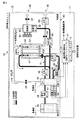
次に、図3を参照して、燃料電池ユニット10の内部構成を説明する。
Next, the internal configuration of the
燃料電池ユニット10は、発電部40と、燃料電池制御部41とをから構成される。燃料電池制御部41は、発電部40の発電動作を制御するコントローラ(DMFCコントローラ)を含んでいる。燃料電池制御部41は、情報処理装置18との通信を行う通信制御部としても機能する。発電部40は燃料電池ユニット本体12内に設けられており、また燃料電池制御部41は載置部11内に設けられている。
The
発電部40は、DMFCスタック42、および燃料カートリッジ43を備えている。DMFCスタック42は、化学反応によって発電を行う起電部として機能する燃料電池である。発電動作によってDMFCスタック42は発熱する。この熱がDMFCスタック42周辺のコンポーネントに伝わるのを防止するために、DMFCスタック42の筐体の外周面または内周面は断熱材で覆われている。燃料カートリッジ43には、高濃度のメタノール液が封入されている。
The
また、一般に、ダイレクトメタノール型燃料電池においては、発電効率をあげるためにクロスオーバー現象を低減する必要がある。そのためには、高濃度メタノールを希釈して低濃度化し、これをDMFCスタック42のカソード(燃料極)47に注入することが有効である。この実現のため、燃料電池ユニット10では、希釈循環システムを採用している。希釈循環システム内に設けられる流路は、液体流路と気体流路とに大別される。
In general, in a direct methanol fuel cell, it is necessary to reduce the crossover phenomenon in order to increase power generation efficiency. For this purpose, it is effective to dilute high concentration methanol to lower the concentration and inject it into the cathode (fuel electrode) 47 of the
まず、液体流路内に配置されるコンポーネントの接続関係について説明する。 First, the connection relationship of components arranged in the liquid flow path will be described.
液体流路においては、燃料電池カートリッジ43の出力部は燃料供給ポンプ44に配管接続され、さらに燃料供給ポンプ44の出力部は混合タンク45に配管接続される。さらに、混合タンク45の出力部は送液ポンプ46に配管接続され、送液ポンプ46の出力部は送液バルブ31を介してDMFCスタック42の燃料極47に配管接続される。さらに燃料極47の出力部は混合タンク45に配管接続される。送液ポンプ46の動力により、液体燃料であるメタノール水溶液は、混合タンク45とDMFCスタック42との間で循環する。このように送液ポンプ46の動力によってメタノール水溶液が循環(還流)する液体流路を「第1の液体流路」と称するものとする。なお、送液ポンプ46は、燃料極47の入力側に設ける代わりに、燃料極47の出力側に設けるようにしてもよい。また、送液バルブ31は、必ずしも必要とされるものではない。
In the liquid flow path, the output portion of the
また、水回収タンク55の出力部は水回収ポンプ56に配管接続され、水回収ポンプ56の出力部は混合タンク45に配管接続される。
The output part of the
上記第1の液体流路における送液ポンプ46と燃料極47との間には分岐が設けられ、この分岐を経由してメタノール水溶液を混合タンク45へと還流させる別の流路(パイプ等)が設けられる。この流路を、「第2の液体流路」と称するものとする。第2の液体流路は、メタノール水溶液中のメタノール濃度の検出を行うために設けられた専用の流路である。第2の液体流路には、送液ポンプ32が設けられ、この送液ポンプ32の出力部は濃度センサ60を介して混合タンク45に接続される。なお、送液ポンプ32は、必ずしも必要とされるものではない。
A branch is provided between the
一方、気体流路においては、送気ポンプ50が送気バルブ51を介してDMFCスタック42の空気極(カソード)52に接続される。空気極52の出力部は凝縮器53に接続される。また、混合タンク45からも、混合タンクバルブ48を介して凝縮器53に接続される。凝縮器53は排気バルブ57を介して排気口58に接続される。この凝縮器53には、水蒸気を効果的に凝縮するフィンが備えられている。また、冷却ファン54は凝縮器53の近傍に配設される。
On the other hand, in the gas flow path, the
次に、燃料電池ユニット10の発電部40の発電メカニズムを、燃料と空気(酸素)の流れに沿って説明する。
Next, the power generation mechanism of the
まず、燃料カートリッジ43内の高濃度メタノールは、燃料供給ポンプ44によって、混合タンク45に流入する。混合タンク45の内部で高濃度メタノールは、回収された水や燃料極47からの低濃度メタノール(発電反応の残余分)等と混合されて希釈され、低濃度メタノールが生成される。低濃度メタノールの濃度は発電効率の高い濃度(例えば3〜6%)を保てるように制御される。この濃度制御は、例えば、濃度センサ60の検出結果を基に、燃料電池制御部41が燃料供給ポンプ44によって混合タンク45に供給される高濃度メタノールの量を制御すること、または、混合タンク45に環流する水の量を水回収ポンプ56等で制御することによって実現できる。
First, the high-concentration methanol in the
また、混合タンク45には、混合タンク45内のメタノール水溶液の液量を検出する液量センサ61、温度を検出する温度センサ64が備えられており、これらの検出結果は燃料電池制御部41に送られて発電部40の制御などに使用される。
Further, the mixing
混合タンク45で希釈されたメタノール水溶液は送液ポンプ46で加圧されて、DMFCスタック42の燃料極(アノード)47に注入される。燃料極47では、メタノールの酸化反応が行われることで電子が発生する。酸化反応で生成される水素イオン(H+)はDMFCスタック42内の固体高分子電解質膜422を透過して空気極(カソード)52に達する。
The aqueous methanol solution diluted in the
一方、燃料極47で行われる酸化反応によって生成される二酸化炭素は、反応に供されなかったメタノール水溶液とともに再び混合タンク45に環流する。二酸化炭素は混合タンク45内で気化し、混合タンクバルブ48を介して、凝縮器53へ向かい、最終的には排気バルブ57を介して、排気口58から外部へ排気される。
On the other hand, the carbon dioxide produced by the oxidation reaction performed at the
他方、空気(酸素)は、吸気口49から取り込まれ、送気ポンプ50で加圧され、送気バルブ51を介し空気極(カソード)52に注入される。空気極52では、酸素(O2)の還元反応が進行し、外部の負荷からの電子(e-)と、燃料極47からの水素イオン(H+)と、酸素(O2)から水(H2O)が水蒸気として生成される。この水蒸気は空気極52から排出され、凝縮器53に入る。凝縮器53では、冷却ファン54によって水蒸気が冷却されて水(液体)となり、水回収タンク55内に一時的に蓄積される。この回収された水は水回収ポンプ56によって混合タンク45へと環流する。
On the other hand, air (oxygen) is taken from the
次に、図4を参照して、情報処理装置18および燃料電池ユニット10それぞれの構成を説明する。
Next, the configurations of the
情報処理装置18は、CPU71、ノースブリッジ72、主メモリ73、ディスプレイコントローラ74、液晶ディスプレイ(LCD)75、サウスブリッジ76、ハードディスクドライブ(HDD)77、複数のPCI(Peripheral Component Interconnect)デバイス78、エンベデッドコントローラ/キーボードコントローラIC(EC/KBC)79、電源コントローラ(PSC)80、電源回路81、リチウムイオンバッテリ(二次電池)82、パワースイッチ83、キーボード(KB)84、ポインティングデバイス85等を備えている。
The
CPU71は本情報処理装置18の動作を制御するために設けられたプロセッサであり、ハードディスクドライブ(HDD)77から主メモリ73にロードされる、オペレーティングシステムおよび各種アプリケーションプログラムを実行する。ノースブリッジ72はCPU71のローカルバスとサウスブリッジ76との間を接続するブリッジデバイスである。ノースブリッジ72には、主メモリ73をアクセス制御するメモリコントローラも内蔵されている。また、ノースブリッジ72は、AGP(Accelerated Graphics Port)バスなどを介してディスプレイコントローラ74との通信を実行する機能も有している。
The
ディスプレイコントローラ74は本情報処理装置18のディスプレイモニタとして使用されるLCD75を制御する。エンベデッドコントローラ/キーボードコントローラIC(EC/KBC)79は、電力管理のためのエンベデッドコントローラと、キーボード(KB)84およびポインティングデバイス85を制御するためのキーボードコントローラとが集積された1チップマイクロコンピュータである。
The
このエンベデッドコントローラ/キーボードコントローラIC(EC/KBC)79は、ユーザによるパワースイッチ83の操作に応じて本情報処理装置18を電源オン/電源オフする機能を有している。本情報処理装置18の電源オン/電源オフの制御は、EC/KBC79と電源コントローラ(PSC)80との共同動作によって実行される。EC/KBC79から送信されるON信号を受けると、電源コントローラ(PSC)80は電源回路81を制御して本情報処理装置18を電源オンする。また、EC/KBC79から送信されるOFF信号を受けると、電源コントローラ(PSC)80は電源回路81を制御して本情報処理装置18を電源オフする。電源回路81は、リチウムイオンバッテリ(二次電池)82からの電力、外部電源(外部電源接続端子86に必要に応じて接続されるACアダプタ)からの電力、および燃料電池ユニット10から供給される電力を選択的に用いて、各コンポーネントへの動作電源を生成する。
The embedded controller / keyboard controller IC (EC / KBC) 79 has a function of powering on / off the
EC/KBC79、電源コントローラ(PSC)80、電源回路81、およびリチウムイオンバッテリ(二次電池)82は、I2Cバスのようなシリアルバス101を介して相互接続されている。
The EC /
燃料電池ユニット10は、上述した発電部40に加え、DMFCコントローラ91、電源回路92等を備えている。DMFCコントローラ91は発電部40の発電動作を制御するコントローラであり、1チップマイクロコンピュータから構成されている。DMFCコントローラ91は、ON/OFFスイッチ112の設定位置に応じて、発電部40の発電動作を許可または禁止するための制御を行う。また、DMFCコントローラ91は、イジェクトレバースイッチ17の位置を検出して、上述のロックの有無を確認する機能を有している。さらに、DMFCコントローラ91は、燃料電池ユニット10が異常状態であるか正常状態であるかを確認する状態チェック機能を有している。状態チェックは、燃料電池ユニット10内に設けられた傾きセンサ(加速度センサ)114と、上述の濃度センサ60、液量センサ61、温度センサ64等を含む各種センサ115とを用いて実行される。
The
発電部40は、DMFCセルスタック42と、希釈巡回システムを構成する複数の補機423とから構成されている。複数の補機423の駆動は、DMFCコントローラ91によって制御される。電源回路92は、複数の補機423それぞれに供給すべき動作電源を生成する。燃料電池ユニット10の発電部40によって所定の値の電力が得られるまでの期間中は、電源回路92は、情報処理装置18の二次電池82から供給される電源から、複数の補機423それぞれに供給すべき動作電源を生成する。発電部40によって所定の値の電力が得られるようになると、電源回路92は、発電部40によって得られる電力から、複数の補機423それぞれに供給すべき動作電源を生成する。
The
このように、複数の補機423を駆動するための電力は情報処理装置18から燃料電池ユニット10に供給されるので、燃料電池ユニット10内には二次電池を設ける必要はない。
As described above, since the electric power for driving the plurality of
次に、燃料電池ユニット10と情報処理装置18との間のインタフェースについて説明する。
Next, an interface between the
燃料電池ユニット10と情報処理装置18との間のインタフェースには、I2Cバスのようなシリアルバス102、ドッキング検出信号線103、ロック状態検出信号線104、および4本の電源線(VCC1,VCC2,VCC3,VCC4)104が使用されている。
The interface between the
シリアルバス102は、情報処理装置18のEC/KBC79と燃料電池ユニット10のDMFCコントローラ91との間で通信を行うためのインタフェースである。EC/KBC79は、シリアルバス102を介してDMFCコントローラ91に各種コマンドを送信することにより、燃料電池ユニット10の動作を制御する。EC/KBC79からDMFCコントローラ91に供給されるコマンドとしては、発電開始コマンド(第1信号)、発電停止コマンド(第2信号)等がある。発電開始コマンドは、発電動作の開始をDMFCコントローラ91に対して指示するコマンドである。発電停止コマンドは、発電動作の停止をDMFCコントローラ91に対して指示するコマンドである。
The
ドッキング検出信号線103は情報処理装置18に燃料電池ユニット10が接続されているか否かを検出するための信号線である。情報処理装置18においては、ドッキング検出信号線103は、プルアップ抵抗R1を介して電源端子に接続されている。一方、燃料電池ユニット10においては、ドッキング検出信号線103は接地されている。情報処理装置18側のドッキングコネクタ21と燃料電池ユニット10側のドッキングコネクタ14とが接続されると、ドッキング検出信号線103の電位は論理“H”レベルから論理“L”レベルに変化する。EC/KBC79は、ドッキング検出信号線103の電位に応じて、情報処理装置18に燃料電池ユニット10が接続されているか否かを検出する。
The docking
ロック状態検出信号線104は、ロック機構の状態を確認するために設けられた信号線である。EC/KBC79は、ロック状態検出信号線104の電圧値に応じて、燃料電池ユニット本体12が情報処理装置18にロックされているか否かを検出する。
The lock state
2つの電源線VCC1,VCC2は、情報処理装置18から燃料電池ユニット10に動作電源を供給するために用いられる。電源線VCC1はDMFCコントローラ91に動作電源を供給するための電源線である。情報処理装置18の電源回路81は、リチウムイオンバッテリ(二次電池)82の電力を用いて、DMFCコントローラ91に供給すべき動作電源を生成し、その動作電源を電源線VCC1を介してDMFCコントローラ91に供給する。電源線VCC2は、複数の補機423を駆動するための電力を燃料電池ユニット10に供給するための電源線であり、スイッチ116を介して燃料電池ユニット10の電源回路92に接続されている。情報処理装置18の電源回路81は、リチウムイオンバッテリ(二次電池)82の電力を用いて、複数の補機423を駆動するための電力を生成し、その電力を電源線VCC2を介して燃料電池ユニット10の電源回路92に供給する。発電部40によって所定の値の電力が得られるようになると、DMFCコントローラ91によってスイッチ116がオフされる。
The two power lines VCC1 and VCC2 are used to supply operating power from the
電源線VCC3は、DMFCスタック42から情報処理装置18に電力を供給するための電源線である。電源線VCC4は、燃料電池ユニット10の外部電源接続端子93に接続された外部電源(ACアダプタ)からの電力を情報処理装置18に供給するための電源線である。情報処理装置18に燃料電池ユニット10を取り付けたドッキング状態においては、情報処理装置18に設けられた外部電源接続端子86は燃料電池ユニット10によって覆われる。このため、情報処理装置18に燃料電池ユニット10を取り付けたドッキング状態においては、外部電源(ACアダプタ)は、燃料電池ユニット10に設けられた外部電源接続端子93に接続される。
The power supply line VCC3 is a power supply line for supplying power from the
情報処理装置18においては、電源線VCC4は、外部電源接続端子86に接続された電源線VCC5にワイヤードOR接続され、そしてその接続ノードが電源回路81に接続されている。
In the
次に、図5を参照して、燃料電池ユニット10の状態遷移について説明する。
Next, the state transition of the
ON/OFFスイッチ112がオフ状態に設定されている間は、燃料電池ユニット10のステートは“ストップステート(0)”に維持される。ON/OFFスイッチ112がユーザによってオン位置に設定されると、EC/KBC79とDMFCコントローラ91との通信が可能となる。EC/KBC79はシリアルバス102を介してDMFCコントローラ91との通信を実行し、DMFCコントローラ91内または専用のEEPROM等に格納された燃料電池識別情報をリードする。EC/KBC79は、リードした燃料電池識別情報に基づいて、情報処理装置18に接続されている燃料電池ユニット10が正当なものであることを確認すると、燃料電池ユニット10を“スタンバイステート”に設定する。
While the ON /
EC/KBC79からの発電開始コマンドを受信すると、燃料電池ユニット10のステートは“ウォームアップステート”に移行する。“ウォームアップステート”においては、図4に示した各ポンプ44、46、50、56、バルブ48、51、57及び冷却ファン54等が駆動され、これにより発電部40の発電動作が開始される。発電部40に設けられたDMFCスタック42に対してメタノール水溶液や空気が注入され初め、発電動作が開始される。また、DMFCスタック42による発電電力は、情報処理装置18に供給され始める。ただし、発電出力は、瞬時に定格値に達するわけではないため、定格値に達するまでの状態を“ウォームアップステート”と呼んでいる。
When the power generation start command is received from the EC /
DMFCスタック42による発電電力が定格値に達すると、燃料電池ユニット10のステートは“オンステート”に移行する。“オンステート”に移行すると、DMFCコントローラ91は、スイッチ116をオフし、各補機423への電力供給源を情報処理装置18からDMFCスタック42に切り替える。
When the power generated by the
“ウォームアップステート”または“オンステート”においてEC/KBC79からの発電停止コマンドを受信すると、燃料電池ユニット10のステートは“クールダウンステート”を経て“スタンバイステート”に移行する。“クールダウンステート”は燃料電池ユニット10の温度を下げるためのステートであり、“クールダウンステート”では、発電部40の発電動作は停止されるが、冷却ファン54、および各ユニットを冷却するために必要な補機が、一定期間駆動される。
When a power generation stop command is received from the EC /
次に、図6を参照して、情報処理装置18の動作に連動して燃料電池ユニット10の動作を制御するという同期制御を実現するための電源制御処理の手順について説明する。
Next, with reference to FIG. 6, the procedure of the power supply control process for realizing the synchronous control of controlling the operation of the
EC/KBC79は、情報処理装置18が電源オフ(サスペンドステート、ハイバネーションステート等も含む)されている期間中において、パワーオンイベントの発生の有無を監視し、情報処理装置18が電源オンされている期間中においてはパワーオフイベントの発生の有無を監視する(ステップS101)。
The EC /
情報処理装置18に設けられたパワースイッチ83がユーザによって押下されるなどのパワーオンイベントが発生すると、情報処理装置18の本体は電源オンされる。情報処理装置18が電源オンされた場合、EC/KBC79は、ドッキング検出信号線103の電位に基づいて、燃料電池ユニット10が情報処理装置18の本体に接続されているか否かを判別する(ステップS102)。
When a power-on event occurs, such as when a
燃料電池ユニット10が情報処理装置18の本体に接続されているならば(ステップS102のYES)、EC/KBC79は、電源回路81を制御して、燃料電池ユニット10に電源を供給する(ステップS103)。ステップS103では、電源回路81は、DMFCコントローラ91を駆動するための電力(VCC1)をDMFCコントローラ91に供給すると共に、各補機を駆動するための電力(VCC2)も電源回路92に対して一時的に供給する。
If the
EC/KBC79は、同期制御の実行が許可されているか否かを判別する(ステップS104)。同期制御を実行するか否かは、例えば、ユーザが予め指定することができる。
The EC /
同期制御の実行が許可されているならば(ステップS104のYES)、EC/KBC79は、電源回路81と共同して、情報処理装置18に外部電源が供給されているか否か、つまり情報処理装置18または燃料電池ユニット10に接続されるACアダプタから電力が供給されているか否かを判別する(ステップS105)。
If the execution of the synchronization control is permitted (YES in step S104), the EC /
外部電源から電力が供給されているならば(ステップS105のYES)、燃料電池ユニット10を動作させる必要がないので、EC/KBC79は電源制御処理を終了する。
If power is supplied from the external power supply (YES in step S105), the
一方、外部電源から電力が供給されていないならば(ステップS105のNO)、EC/KBC79は、まず、燃料電池ユニット本体12が情報処理装置18にロックされているか否かを判別する(ステップS106)。ステップS106では、EC/KBC79は、DMFCコントローラ91から出力されるロック状態検出信号線104の電圧値をリードすることで、ロック機構の状態を確認する。
On the other hand, if power is not supplied from the external power source (NO in step S105), the EC /
もし燃料電池ユニット本体12と情報処理装置18とのロックが解除された状態であるならば(ステップS106のNO)、発電動作を開始すると安全上の問題があるので、EC/KBC79は電源制御処理を終了する。
If the fuel cell unit
燃料電池ユニット本体12が情報処理装置18にロックされていることが確認されたならば(ステップS106のYES)、EC/KBC79は、燃料電池ユニット10の状態をシリアルバス102を介してDMFCコントローラ91に問い合わせることにより、燃料電池ユニット10が異常状態(傾き異常、内部温度異常、燃料切れ、水漏れ等、)であるか否かを判別する(ステップS107)。
If it is confirmed that the fuel
燃料電池ユニット10に異常が発生していたならば(ステップS107のYES)、発電動作を開始すると安全上問題があるので、EC/KBC79は電源制御処理を終了する。
If an abnormality has occurred in the fuel cell unit 10 (YES in step S107), there is a safety problem when the power generation operation is started, so the EC /
燃料電池ユニット10に異常が発生していないならば(ステップS107のNO)、EC/KBC79は、シリアルバス102を介して発電開始コマンドをDMFCコントローラ91に送信して発電部40の発電動作を開始させる(ステップS108)。なお、燃料電池ユニット10へのVCC2の供給を、ステップS108において開始してもよい。
If no abnormality has occurred in the fuel cell unit 10 (NO in step S107), the EC /
この後、EC/KBC79は、電源回路81と共同して、発電部40から供給される電力が所定値の値(定格値)に達したかどうかを判別する(ステップS109)。発電部40から供給される電力が所定値の値(定格値)に達したならば、EC/KBC79は、電源回路81を制御して、燃料電池ユニット10へのVCC2の供給を停止する(ステップS110)。電源回路81は、情報処理装置18を駆動する電源を二次電池82から燃料電池ユニット10からの電力(VCC4)に切り替える。また、燃料電池ユニット10においては、DMFCコントローラ91は、スイッチ116をオフし、これによって各補機を駆動する電力をVCC2から発電部40からの電力に切り替える。
Thereafter, the EC /
このようにして、本実施形態においては、情報処理装置18のパワーオンに連動して燃料電池ユニット10の発電動作が自動的に開始される。
Thus, in the present embodiment, the power generation operation of the
なお、情報処理装置18がパワーオンされている状態で、情報処理装置18に燃料電池ユニット10が接続された場合も、EC/KBC79は、ステップS102以降の処理を実行する。これにより、パワーオンされている情報処理装置18に燃料電池ユニット10が接続された場合にも、燃料電池ユニット10の発電動作が自動的に開始される。
Even when the
もしパワーオフイベントが発生したならば、EC/KBC79は、情報処理装置18をパワーオフするための電源シーケンス処理の中で、以下の処理を実行する。
If a power-off event occurs, the EC /
EC/KBC79は、ドッキング検出信号線103の電位に基づいて、燃料電池ユニット10が情報処理装置18の本体に接続されているか否かを判別する(ステップS111)。燃料電池ユニット10が情報処理装置18の本体に接続されているならば(ステップS111のYES)、EC/KBC79は、同期制御の実行が許可されているか否かを判別する(ステップS112)。同期制御の実行が許可されているならば(ステップS112のYES)、EC/KBC79は、シリアルバス102を介して発電停止コマンドをDMFCコントローラ91に送信して発電部40の発電動作を停止させる(ステップS113)。
The EC /
このようにして、本実施形態においては、情報処理装置18のパワーオフに連動して燃料電池ユニット10の発電動作が自動的に停止される。
Thus, in the present embodiment, the power generation operation of the
なお、本発明は上記実施形態そのままに限定されるものではなく、実施段階ではその要旨を逸脱しない範囲で構成要素を変形して具体化できる。また、上記実施形態に開示されている複数の構成要素の適宜な組み合わせにより、種々の発明を形成できる。例えば、実施形態に示される全構成要素から幾つかの構成要素を削除してもよい。さらに、異なる実施形態にわたる構成要素を適宜組み合わせてもよい。 Note that the present invention is not limited to the above-described embodiment as it is, and can be embodied by modifying the components without departing from the scope of the invention in the implementation stage. In addition, various inventions can be formed by appropriately combining a plurality of constituent elements disclosed in the embodiment. For example, some components may be deleted from all the components shown in the embodiment. Furthermore, constituent elements over different embodiments may be appropriately combined.
10…燃料電池ユニット、11…載置部、12…燃料電池ユニット本体、14,21…ドッキングコネクタ、40…発電部、41…燃料電池制御部、42…DMFCスタック、45…混合タンク、79…EC/KBC、80…電源コントローラ(PSC)、81,92…電源回路、91…DMFCコントローラ。
DESCRIPTION OF
Claims (15)
前記本体内に設けられ、前記本体の電源がオンされた場合、前記燃料電池の発電動作を開始させる制御部とを具備することを特徴とする情報処理装置。 A main body to which a fuel cell unit including a fuel cell and a controller for controlling a power generation operation of the fuel cell is connectable;
An information processing apparatus comprising: a control unit that is provided in the main body and starts a power generation operation of the fuel cell when the power source of the main body is turned on.
前記燃料電池にて生成される水を前記混合タンクに送出するポンプとをさらに具備し、
、前記コントローラは前記ポンプの駆動を制御することを特徴とする請求項1記載の情報処理装置。 A mixing tank that mixes liquid fuel and water to generate an aqueous fuel solution to be supplied to the fuel cell;
A pump for sending water generated in the fuel cell to the mixing tank;
The information processing apparatus according to claim 1, wherein the controller controls driving of the pump.
前記二次電池を備え且つ前記燃料電池ユニットに接続可能な本体と、
前記本体の電源がオンされた場合、前記本体に前記燃料電池ユニットが接続されているか否かを判別する手段と、
前記本体に前記燃料電池ユニットが接続されている場合、前記燃料電池を駆動するための電力を前記二次電池を用いて前記燃料電池ユニットに供給すると共に、前記燃料電池の発電動作を開始させる手段と、
を具備することを特徴とする情報処理装置。 An information processing apparatus that can be driven by a secondary battery and a fuel cell unit, wherein the fuel cell unit includes a fuel cell and a controller that controls a power generation operation of the fuel cell,
A main body comprising the secondary battery and connectable to the fuel cell unit;
Means for determining whether or not the fuel cell unit is connected to the main body when the main body is powered on;
When the fuel cell unit is connected to the main body, means for supplying electric power for driving the fuel cell to the fuel cell unit using the secondary battery and starting a power generation operation of the fuel cell When,
An information processing apparatus comprising:
前記燃料電池にて生成される水を前記混合タンクに送出するポンプとをさらに具備し、
前記コントローラは前記ポンプの駆動を制御することを特徴とする請求項8記載の情報処理装置。 A mixing tank that mixes liquid fuel and water to generate an aqueous fuel solution to be supplied to the fuel cell;
A pump for sending water generated in the fuel cell to the mixing tank;
The information processing apparatus according to claim 8, wherein the controller controls driving of the pump.
前記本体が電源オンされた場合、前記燃料電池ユニットが前記本体に接続されているか否かを判別し、
前記燃料電池ユニットが前記情報処理装置に接続されていることが判別された場合、前記燃料電池の発電動作を開始させることを特徴とする動作制御方法。 An operation control method for controlling the operation of a fuel cell unit that can be connected to an information processing device and includes a fuel cell and a controller that controls the power generation operation of the fuel cell,
When the main body is powered on, determine whether the fuel cell unit is connected to the main body,
When it is determined that the fuel cell unit is connected to the information processing apparatus, a power generation operation of the fuel cell is started.
前記燃料電池ユニットが異常状態ではないことが判別された場合、前記燃料電池の発電動作を開始させることを特徴とする請求項11記載の動作制御方法。 When the information processing device is powered on, determine whether the fuel cell unit is in an abnormal state,
The operation control method according to claim 11, wherein when it is determined that the fuel cell unit is not in an abnormal state, the power generation operation of the fuel cell is started.
前記外部電源から電力が供給されていないことが判別された場合、前記燃料電池の発電動作を開始させることを特徴とする請求項11記載の情報処理装置。 When the information processing apparatus is powered on, determine whether power is supplied to the information processing apparatus from an external power source,
The information processing apparatus according to claim 11, wherein when it is determined that power is not supplied from the external power source, the power generation operation of the fuel cell is started.
Priority Applications (2)
| Application Number | Priority Date | Filing Date | Title |
|---|---|---|---|
| JP2005205897A JP2007026832A (en) | 2005-07-14 | 2005-07-14 | Information processor and motion control method |
| US11/486,166 US20070015018A1 (en) | 2005-07-14 | 2006-07-14 | Information processing apparatus and operation control method |
Applications Claiming Priority (1)
| Application Number | Priority Date | Filing Date | Title |
|---|---|---|---|
| JP2005205897A JP2007026832A (en) | 2005-07-14 | 2005-07-14 | Information processor and motion control method |
Publications (2)
| Publication Number | Publication Date |
|---|---|
| JP2007026832A true JP2007026832A (en) | 2007-02-01 |
| JP2007026832A5 JP2007026832A5 (en) | 2008-07-10 |
Family
ID=37661990
Family Applications (1)
| Application Number | Title | Priority Date | Filing Date |
|---|---|---|---|
| JP2005205897A Withdrawn JP2007026832A (en) | 2005-07-14 | 2005-07-14 | Information processor and motion control method |
Country Status (2)
| Country | Link |
|---|---|
| US (1) | US20070015018A1 (en) |
| JP (1) | JP2007026832A (en) |
Families Citing this family (9)
| Publication number | Priority date | Publication date | Assignee | Title |
|---|---|---|---|---|
| JP2005338184A (en) * | 2004-05-24 | 2005-12-08 | Toshiba Corp | Information processor and display control method |
| JP2005338185A (en) * | 2004-05-24 | 2005-12-08 | Toshiba Corp | Information processor and display control method |
| JP2006030911A (en) * | 2004-07-21 | 2006-02-02 | Toshiba Corp | Information processor and display control method |
| JP4709519B2 (en) | 2004-09-30 | 2011-06-22 | 株式会社東芝 | Information processing apparatus and display control method |
| JP2007025060A (en) * | 2005-07-13 | 2007-02-01 | Toshiba Corp | Information processor and video signal output control method |
| JP5427379B2 (en) * | 2007-08-30 | 2014-02-26 | ヤマハ発動機株式会社 | Fuel cell system and control method thereof |
| US8119301B2 (en) * | 2008-02-18 | 2012-02-21 | Shiro Matsuo | Cooling system for fuel cell stack shutdown |
| JP5595231B2 (en) * | 2010-11-05 | 2014-09-24 | 本田技研工業株式会社 | Fuel cell system |
| CN103294376B (en) * | 2012-02-24 | 2016-08-17 | 联想(北京)有限公司 | Electronic equipment and display packing and terminal unit and the method for switch mode |
Family Cites Families (10)
| Publication number | Priority date | Publication date | Assignee | Title |
|---|---|---|---|---|
| NL194144C (en) * | 1993-09-15 | 2001-07-03 | Ericsson Inc | Power supply system for a plug-in module. |
| US5990575A (en) * | 1997-07-22 | 1999-11-23 | Flaugher; David J. | Auxiliary power source control systems and methods |
| US7030514B2 (en) * | 2001-08-17 | 2006-04-18 | Dynagen Technologies Incorporated | Power transfer switch assembly |
| EP1311048A3 (en) * | 2001-11-09 | 2005-02-16 | Matsushita Electric Industrial Co., Ltd. | Power controller, power generation system and control method of power controller |
| JP2003223243A (en) * | 2002-01-29 | 2003-08-08 | Toshiba Corp | Information equipment |
| US7230933B2 (en) * | 2002-04-17 | 2007-06-12 | Microsoft Corporation | Reducing idle power consumption in a networked battery operated device |
| JP3899518B2 (en) * | 2002-09-30 | 2007-03-28 | カシオ計算機株式会社 | FUEL CELL SYSTEM, ITS DRIVE CONTROL METHOD, AND ELECTRONIC DEVICE HAVING POWER SUPPLY SYSTEM |
| JP3830910B2 (en) * | 2003-03-04 | 2006-10-11 | 株式会社東芝 | Fuel cell unit and status display control method |
| US7482091B2 (en) * | 2003-07-09 | 2009-01-27 | The Gillette Company | Fuel cartridge interconnect for portable fuel cells |
| JP2005108716A (en) * | 2003-09-30 | 2005-04-21 | Toshiba Corp | Fuel cell |
-
2005
- 2005-07-14 JP JP2005205897A patent/JP2007026832A/en not_active Withdrawn
-
2006
- 2006-07-14 US US11/486,166 patent/US20070015018A1/en not_active Abandoned
Also Published As
| Publication number | Publication date |
|---|---|
| US20070015018A1 (en) | 2007-01-18 |
Similar Documents
| Publication | Publication Date | Title |
|---|---|---|
| JP2007026832A (en) | Information processor and motion control method | |
| US20060083966A1 (en) | Fuel cell unit and method for controlling liquid volume | |
| JP2008034254A (en) | Fuel cell system and its operation control method | |
| US20070072023A1 (en) | Fuel cell unit, information processing apparatus, and power supply control method for information processing apparatus | |
| US7618727B2 (en) | Fuel cell unit, control method for fuel cell unit, and information processing apparatus | |
| US20060040147A1 (en) | Liquid circulation type fuel cell | |
| JP4837015B2 (en) | Information processing apparatus system and charging control method | |
| US20070048566A1 (en) | Fuel cell unit, control method for fuel cell unit, and information processing apparatus | |
| JP2005078925A (en) | Battery unit and feeding control method | |
| JP2007018992A (en) | Fuel cell system and operation control method of fuel cell system | |
| US20040183501A1 (en) | Electronic apparatus, electronic system, and method of controlling operation of the same | |
| US7620805B2 (en) | Apparatus for updating program in a fuel cell unit | |
| US7879473B2 (en) | Fuel cell unit, control method thereof, information processing apparatus, and power supply control method thereof | |
| JP2007066747A (en) | Fuel cell unit and measurement value correction method | |
| JP2006294471A (en) | Fuel cell unit and method for calculating remaining amount of fuel | |
| JP2007273388A (en) | Fuel cell system and operation control method therefor | |
| JP2005078353A (en) | Electronic device system and method for supplying electric power | |
| JP2008117540A (en) | Fuel cell unit | |
| JP2005108711A (en) | Battery unit and electric power supply control method | |
| JP2005108712A (en) | Battery unit and output control method | |
| JP2006147179A (en) | Fuel cell unit | |
| JP2004296127A (en) | Electronic equipment, fuel cell unit, and method of controlling operation of electronic equipment | |
| JP2007087701A (en) | Electronic apparatus and starting method of fuel cell | |
| JP2008117536A (en) | Fuel cell | |
| JP4805551B2 (en) | Information processing apparatus system and power supply method |
Legal Events
| Date | Code | Title | Description |
|---|---|---|---|
| A521 | Written amendment |
Free format text: JAPANESE INTERMEDIATE CODE: A523 Effective date: 20080527 |
|
| A621 | Written request for application examination |
Free format text: JAPANESE INTERMEDIATE CODE: A621 Effective date: 20080527 |
|
| A761 | Written withdrawal of application |
Free format text: JAPANESE INTERMEDIATE CODE: A761 Effective date: 20100416 |